To better understand the causes of air pollution, the pollutants can be categorized into 3 separate types, natural, industrial and automotive.
|
|
|
- Deirdre York
- 6 years ago
- Views:
Transcription
1 AIR POLLUTION Стр. 1 из 4 AIR POLLUTION Introduction The earth's atmosphere, at or near sea level, consists approximately of 78% nitrogen, 21% oxygen and 1% other gases. If it were possible to remain in this state, 100% clean air would result. However, many varied causes allow other gases and particulates to mix with the clean air, causing the air to become unclean or polluted. Certain of these pollutants are visible while others are invisible, with each having the capability of causing distress to the eyes, ears, throat, skin and respiratory system. Should these pollutants be concentrated in a specific area and under the right conditions, death could result due to the displacement or chemical change of the oxygen content in the air. These pollutants can cause much damage to the environment and to the many man made objects that are exposed to the elements. To better understand the causes of air pollution, the pollutants can be categorized into 3 separate types, natural, industrial and automotive. Natural Pollutants Natural pollution has been present on earth before man appeared, and is still a factor to be considered when discussing air pollution, although it causes only a small percentage of the present overall pollution problem existing in our country. It is the direct result of decaying organic matter, wind born smoke and particulates from such natural events as plains and forest fires (ignited by heat or lightning), volcanic ash, sand and dust which can spread over a large area of the countryside. Such a phenomenon of natural pollution has been recent volcanic eruptions, with the resulting plume of smoke, steam and volcanic ash blotting out the sun's rays as it spreads and rises higher into the atmosphere, where the upper air currents catch and carry the smoke and ash, while condensing the steam back into water vapor. As the water vapor, smoke and ash traveled on their journey, the smoke dissipates into the atmosphere while the ash and moisture settle back to earth in a trail hundred of miles long. In many cases, lives are lost and millions of dollars of property damage result, and ironically, man can only stand by and watch it happen. Industrial Pollutants Industrial pollution is caused primarily by industrial processes, the burning of coal, oil and natural gas, which in turn produces smoke and fumes. Because the burning fuels contain much sulfur, the principal ingredients of smoke and fumes are sulfur dioxide (SO 2 ) and particulate matter. This type of pollutant occurs most severely during still, damp and cool weather, such as at night. Even in its less severe form, this pollutant is not confined to just cities. Because of air movements, the pollutants move for miles over the surrounding countryside,
2 AIR POLLUTION Стр. 2 из 4 leaving in its path a barren and unhealthy environment for all living things. Working with Federal, State and Local mandated rules, regulations and by carefully monitoring the emissions, industries have greatly reduced the amount of pollutant emitted from their industrial sources, striving to obtain an acceptable level. Because of the mandated industrial emission clean up, many land areas and streams in and around the cities that were formerly barren of vegetation and life, have now begun to move back in the direction of nature's intended balance. Automotive Pollutants The third major source of air pollution is the automotive emissions. The emissions from the internal combustion engine were not an appreciable problem years ago because of the small number of registered vehicles and the nation's small highway system. However, during the early 1950's, the trend of the American people was to move from the cities to the surrounding suburbs. This caused an immediate problem in the transportation areas because the majority of the suburbs were not afforded mass transit conveniences. This lack of transportation created an attractive market for the automobile manufacturers, which resulted in a dramatic increase in the number of vehicles produced and sold, along with a marked increase in highway construction between cities and the suburbs. Multivehicle families emerged with much emphasis placed on the individual vehicle per family member. As the increase in vehicle ownership and usage occurred, so did the pollutant levels in and around the cities, as the suburbanites drove daily to their businesses and employment in the city and its fringe area, returning at the end of the day to their homes in the suburbs. It was noted that a fog and smoke type haze was being formed and at times, remained in suspension over the cities and did not quickly dissipate. At first this "smog'', derived from the words "smoke'' and "fog'', was thought to result from industrial pollution but it was determined that the automobile emissions shared the blame. It was discovered that when normal automobile emissions were exposed to sunlight for a period of time, complex chemical reactions would take place. It is now known that smog is a photo chemical layer and was developed when certain oxides of nitrogen (NOx) and unburned hydrocarbons (HC) from the automobile emissions are exposed to sunlight. Pollution was more severe when the smog would become stagnant over an area in which a warm layer of air would settle over the top of a cooler air mass at ground level, trapping and holding the automobile emissions, instead of the emissions being dispersed and diluted through normal air flows. This type of air stagnation was given the name "Temperature Inversion''. Temperature Inversion In normal weather situations, the surface air is warmed by the heat radiating from the earth's surface and the sun's rays and will rise upward, into the atmosphere, to be cooled through a convection type heat expands with the cooler upper air. As the warm air rises, the surface pollutants are carried upward and dissipated into the atmosphere. When a temperature inversion occurs, we find the higher air is no longer cooler but warmer than the surface air, causing the cooler surface air to become trapped and unable to move. This warm air blanket can extend from above ground level to a few hundred or even a few thousand feet into the air. As the surface air is
3 AIR POLLUTION Стр. 3 из 4 trapped, so are the pollutants, causing a severe smog condition. Should this stagnant air mass extend to a few thousand feet high, enough air movement with the inversion takes place to allow the smog layer to rise above ground level but the pollutants still cannot dissipate. This inversion can remain for days over an area, with only the smog level rising or lowering from ground level to a few hundred feet high. Meanwhile, the pollutant levels increases, causing eye irritation, respirator problems, reduced visibility, plant damage and in some cases, cancer type diseases. This inversion phenomenon was first noted in the Los Angeles, California area. The city lies in a basin type of terrain and during certain weather conditions, a cold air mass is held in the basin while a warmer air mass covers it like a lid. Because this type of condition was first documented as prevalent in the Los Angeles area, this type of smog was named Los Angeles Smog, although it occurs in other areas where a large concentration of automobiles are used and the air remains stagnant for any length of time. Internal Combustion Engine Pollutants Consider the internal combustion engine as a machine in which raw materials must be placed so a finished product comes out. As in any machine operation, a certain amount of wasted material is formed. When we relate this to the internal combustion engine, we find that by putting in air and fuel, we obtain power from this mixture during the combustion process to drive the vehicle. The by-product or waste of this power is, in part, heat and exhaust gases with which we must concern ourselves. Heat Transfer The heat from the combustion process can rise to over 4000 F (2204 C). The dissipation of this heat is controlled by a ram air effect, the use of cooling fans to cause air flow and having a liquid coolant solution surrounding the combustion area and transferring the heat of combustion through the cylinder walls and into the coolant. The coolant is then directed to a thin-finned, multi-tubed radiator, from which the excess heat is transferred to the outside air by 1 or all of the 3 heat transfer methods, conduction, convection or radiation. The cooling of the combustion area is an important part in the control of exhaust emissions. To understand the behavior of the combustion and transfer of its heat, consider the air/fuel charge. It is ignited and the flame front burns progressively across the combustion chamber until the burning charge reaches the cylinder walls. Some of the fuel in contact with the walls is not hot enough to burn, thereby snuffing out or quenching the combustion process. This leaves unburned fuel in the combustion chamber. This unburned fuel is then forced out of the cylinder along with the exhaust gases and into the exhaust system. Many attempts have been made to minimize the amount of unburned fuel in the combustion chambers due to the snuffing out or quenching, by increasing the coolant temperature and lessening the contact area of the coolant around the combustion area. Design limitations within the combustion chambers prevent the complete burning of the air/fuel charge, so a certain amount of the unburned fuel is still expelled into the exhaust system, regardless of modifications to the engine.
4 AIR POLLUTION Стр. 4 из 4 Chilton Automotive Information Systems Thomson Delmar Learning.
5 EXHAUST EMISSIONS Стр. 1 из 5 EXHAUST EMISSIONS Composition Of The Exhaust Gases The exhaust gases emitted into the atmosphere are a combination of burned and unburned fuel. To understand the exhaust emission and its composition review some basic chemistry. When the air/fuel mixture is introduced into the engine, we are mixing air, composed of nitrogen (78%), oxygen (21%) and other gases (1%) with the fuel, which is 100% hydrocarbons (HC), in a semi-controlled ratio. As the combustion process is accomplished, power is produced to move the vehicle while the heat of combustion is transferred to the cooling system. The exhaust gases are then composed of nitrogen, a diatomic gas (N 2 ), the same as was introduced in the engine, carbon dioxide (CO 2 ), the same gas that is used in beverage carbonation and water vapor (H 2 O). The nitrogen (N 2 ), for the most part passes through the engine unchanged, while the oxygen (O 2 ) reacts (burns) with the hydrocarbons (HC) and produces the carbon dioxide (CO 2 ) and the water vapors (H 2 O). If this chemical process would be the only process to take place, the exhaust emissions would be harmless. However, during the combustion process, other pollutants are formed and are considered dangerous. These pollutants are carbon monoxide (CO), hydrocarbons (HC), oxides of nitrogen (NOx) oxides of sulfur (SOx) and engine particulates. HYDROCARBONS Hydrocarbons (HC) are essentially unburned fuel that have not been successfully burned during the combustion process or have escaped into the atmosphere through fuel evaporation. The main sources of incomplete combustion are rich air/fuel mixtures, low engine temperatures and improper spark timing. The main sources of hydrocarbon emission through fuel evaporation come from the vehicle's fuel tank and carburetor bowl. To reduce combustion hydrocarbon emission, engine modifications were made to minimize dead space and surface area in the combustion chamber. In addition the air/fuel mixture was made more lean through improved carburetion, fuel injection and by the addition of external controls to aid in further combustion of the hydrocarbons outside the engine. Two such methods were the addition of an air injection system, to inject fresh air into the exhaust manifolds and the installation of a catalytic converter, a unit that is able to burn traces of hydrocarbons without affecting the internal combustion process or fuel economy. To control hydrocarbon emissions through fuel evaporation, modifications were made to the fuel tank and carburetor bowl to allow storage of the fuel vapors during periods of engine shut-down, and at specific times during engine operation, to purge and burn these same vapors by blending them with the air/fuel mixture. CARBON MONOXIDE
6 EXHAUST EMISSIONS Стр. 2 из 5 Carbon monoxide is formed when not enough oxygen is present during the combustion process to convert carbon (C) to carbon dioxide (CO 2 ). An increase in the carbon monoxide (CO) emission is normally accompanied by an increase in the hydrocarbon (HC) emission because of the lack of oxygen to completely burn all of the fuel mixture. Carbon monoxide (CO) also increases the rate at which the photo chemical smog is formed by speeding up the conversion of nitric oxide (NO) to nitrogen dioxide (NO 2 ). To accomplish this, carbon monoxide (CO) combines with oxygen (O 2 ) and nitrogen dioxide (NO 2 ) to produce carbon dioxide (CO 2 ) and nitrogen dioxide (NO 2 ). (CO + O 2 + NO = CO 2 + NO 2 ). The dangers of carbon monoxide, which is an odorless, colorless toxic gas are many. When carbon monoxide is inhaled into the lungs and passed into the blood stream, oxygen is replaced by the carbon monoxide in the red blood cells, causing a reduction in the amount of oxygen being supplied to the many parts of the body. This lack of oxygen causes headaches, lack of coordination, reduced mental alertness and should the carbon monoxide concentration be high enough, death could result. NITROGEN Normally, nitrogen is an inert gas. When heated to approximately 2500 F (1371 C) through the combustion process, this gas becomes active and causes an increase in the nitric oxide (NOx) emission. OZONE Oxides of nitrogen (NOx) are composed of approximately 97-98% nitric oxide (NO). Nitric oxide is a colorless gas but when it is passed into the atmosphere, it combines with oxygen and forms nitrogen dioxide (NO 2 ). The nitrogen dioxide then combines with chemically active hydrocarbons (HC) and when in the presence of sunlight, causes the formation of photo chemical smog. To further complicate matters, some of the nitrogen dioxide (NO 2 ) is broken apart by the sunlight to form nitric oxide and oxygen. (NO 2 + sunlight = NO + O). This single atom of oxygen then combines with diatomic (meaning 2 atoms) oxygen (O 2 ) to form ozone (O 3 ). Ozone is one of the smells associated with smog. It has a pungent and offensive odor, irritates the eyes and lung tissues, affects the growth of plant life and causes rapid deterioration of rubber products. Ozone can be formed by sunlight as well as electrical discharge into the air. The most common discharge area on the automobile engine is the secondary ignition electrical system, especially when inferior quality spark plug cables are used. As the surge of high voltage is routed through the secondary cable, the circuit builds up an electrical field around the wire, acting upon the oxygen in the surrounding air to form the ozone. The faint glow along the cable with the engine running that may be visible on a dark night, is called the "corona discharge.'' It is the result of the electrical field passing from a high along the cable, to a low in the surrounding air, which forms the ozone gas. The combination of corona and ozone has been a major cause of cable deterioration. Recently, different types and better quality insulating materials have lengthened the life of the electrical cables. Although ozone at ground level can be harmful, ozone is beneficial to the earth's inhabitants. By having a concentrated ozone layer called the "ozonosphere''
7 EXHAUST EMISSIONS Стр. 3 из 5 between 10 and 20 miles (16-32km) up in the atmosphere, much of the ultra violet radiation from the sun's rays are absorbed and screened. If this ozone layer were not present, much of the earth's surface would be burned, dried and unfit for human life. There is much discussion concerning the ozone layer and its density. A feeling exists that this protective layer of ozone is slowly diminishing and corrective action must be directed to this problem. Much experimenting is presently being conducted to determine if a problem exists and if so, the short and long term effects of the problem and how it can be remedied. OXIDES OF SULFUR Oxides of sulfur (SOx) were initially ignored in the exhaust system emissions, since the sulfur content of gasoline as a fuel is less than 1 / 10 of 1%. Because of this small amount, it was felt that it contributed very little to the overall pollution problem. However, because of the difficulty in solving the sulfur emissions in industrial pollutions and the introduction of catalytic converter to the automobile exhaust systems, a change was mandated. The automobile exhaust system, when equipped with a catalytic converter, changes the sulfur dioxide (SO 2 ) into the sulfur trioxide (SO 3 ). When this combines with water vapors (H 2 O), a sulfuric acid mist (H 2 SO 4 ) is formed and is a very difficult pollutant to handle and is extremely corrosive. This sulfuric acid mist that is formed, is the same mist that rises from the vents of an automobile storage battery when an active chemical reaction takes place within the battery cells. When a large concentration of vehicles equipped with catalytic converters are operating in an area, this acid mist will rise and be distributed over a large ground area causing land, plant, crop, paints and building damage. PARTICULATE MATTER A certain amount of particulate matter is present in the burning of any fuel, with carbon constituting the largest percentage of the particulates. In gasoline, the remaining percentage of particulates is the burned remains of the various other compounds used in its manufacture. When a gasoline engine is in good internal condition, the particulate emissions are low but as the engine wears internally, the particulate emissions increase. By visually inspecting the tail pipe emissions, a determination can be made as to where an engine defect may exist. An engine with light gray smoke emitting from the tail pipe normally indicates an increase in the oil consumption through burning due to internal engine wear. Black smoke would indicate a defective fuel delivery system, causing the engine to operate in a rich mode. Regardless of the color of the smoke, the internal part of the engine or the fuel delivery system should be repaired to a "like new'' condition to prevent excess particulate emissions. Diesel and turbine engines emit a darkened plume of smoke from the exhaust system because of the type of fuel used. Emission control regulations are mandated for this type of emission and more stringent measures are being used to prevent excess emission of the particulate matter. Electronic components are being introduced to control the injection of the fuel at precisely the proper time of piston travel, to achieve the optimum in fuel ignition and fuel usage. Other particulate after-burning components are being tested to achieve a cleaner particular emission.
8 EXHAUST EMISSIONS Стр. 4 из 5 Good grades of engine lubricating oils should be used, meeting the manufacturers specification. "Cut-rate'' oils can contribute to the particulate emission problem because of their low "flash'' or ignition temperature point. Such oils burn prematurely during the combustion process causing emissions of particulate matter. The cooling system is an important factor in the reduction of particulate matter. With the cooling system operating at a temperature specified by the manufacturer, the optimum of combustion will occur. The cooling system must be maintained in the same manner as the engine oiling system, as each system is required to perform properly in order for the engine to operate efficiently for a long time. Other Automobile Emission Sources Before emission controls were mandated on the internal combustion engines, other sources of engine pollutants were discovered, along with the exhaust emission. It was determined the engine combustion exhaust produced 60% of the total emission pollutants, fuel evaporation from the fuel tank and carburetor vents produced 20%, with the another 20% being produced through the crankcase as a by-product of the combustion process. CRANKCASE EMISSIONS Crankcase emissions are made up of water, acids, unburned fuel, oil fumes and particulates. The emissions are classified as hydrocarbons (HC) and are formed by the small amount of unburned, compressed air/fuel mixture entering the crankcase from the combustion area during the compression and power strokes, between the cylinder walls and piston rings. The head of the compression and combustion help to form the remaining crankcase emissions. Since the first engines, crankcase emissions were allowed to go into the air through a road draft tube, mounted on the lower side of the engine block. Fresh air came in through an open oil filler cap or breather. The air passed through the crankcase mixing with blow-by gases. The motion of the vehicle and the air blowing past the open end of the road draft tube caused a low pressure area at the end of the tube. Crankcase emissions were simply drawn out of the road draft tube into the air. To control the crankcase emission, the road draft tube was deleted. A hose and/or tubing was routed from the crankcase to the intake manifold so the blow-by emission could be burned with the air/fuel mixture. However, it was found that intake manifold vacuum, used to draw the crankcase emissions into the manifold, would vary in strength at the wrong time and not allow the proper emission flow. A regulating type valve was needed to control the flow of air through the crankcase. Testing, showed the removal of the blow-by gases from the crankcase as quickly as possible, was most important to the longevity of the engine. Should large accumulations of blow-by gases remain and condense, dilution of the engine oil would occur to form water, soots, resins, acids and lead salts, resulting in the formation of sludge and varnishes. This condensation of the blow-by gases occur more frequently on vehicles used in numerous starting and stopping conditions, excessive idling and when the engine is not allowed to attain normal operating temperature through short runs. The crankcase purge control or PCV system will be described in detail later in this section.
9 EXHAUST EMISSIONS Стр. 5 из 5 FUEL EVAPORATIVE EMISSIONS Gasoline fuel is a major source of pollution, before and after it is burned in the automobile engine. From the time the fuel is refined, stored, pumped and transported, again stored until it is pumped into the fuel tank of the vehicle, the gasoline gives off unburned hydrocarbons (HC) into the atmosphere. Through redesigning of the storage areas and venting systems, the pollution factor has been diminished but not eliminated, from the refinery standpoint. However, the automobile still remained the primary source of vaporized, unburned hydrocarbon (HC) emissions. Fuel pumped form an underground storage tank is cool, but when exposed to a warmer ambient temperature, it will expand. Before controls were mandated, an owner would fill the fuel tank with fuel from an underground storage tank and park the vehicle for some time in warm area, such as a parking lot. As the fuel would warm, it would expand and should no provisions or area be provided for the expansion, the fuel would spill out the filler neck and onto the ground, causing hydrocarbon (HC) pollution and creating a severe fire hazard. To correct this condition, the vehicle manufacturers added overflow plumbing and/or gasoline tanks with built in expansion areas or domes. However, this did not control the fuel vapor emission from the fuel tank and the carburetor bowl. It was determined that most of the fuel evaporation occurred when the vehicle was stationary and the engine not operating. Most vehicles carry 5-25 gallons (19-95 liters) of gasoline. Should a large concentration of vehicles be parked in one area, such as a large parking lot, excessive fuel vapor emissions would take place, increasing as the temperature increases. To prevent the vapor emission from escaping into the atmosphere, the fuel system is designed to trap the fuel vapors while the vehicle is stationary, by sealing the fuel system from the atmosphere. A storage system is used to collect and hold the fuel vapors from the carburetor and the fuel tank when the engine is not operating. When the engine is started, the storage system is then purged of the fuel vapors, which are drawn into the engine and burned with the air/fuel mixture. Chilton Automotive Information Systems Thomson Delmar Learning.

10 EMISSION CONTROLS Стр. 1 из 51 EMISSION CONTROLS Introduction There are three sources of automotive pollutants: crankcase fumes, exhaust gases and gasoline evaporation. The pollutants formed from these substances can be grouped into three categories: unburned hydrocarbons (HC), carbon monoxide (CO) and oxides of nitrogen (NO x ). The equipment that is used to limit these pollutants is commonly called emission control equipment. The vehicle emission control information label includes instructions for engine control system adjustment Positive Crankcase Ventilation (PCV) System OPERATION The Positive Crankcase Ventilation (PCV) system is used on all vehicles covered by this manual. The PCV system vents harmful combustion blow-by fumes from the engine crankcase into the engine air intake for burning with the fuel and air mixture. The PCV system maximizes oil cleanliness by venting moisture and corrosive fumes from the crankcase. All of the vehicles covered by this manual, except for the 3.0L and the 3.2L SHO engines, utilize a PCV valve. The PCV valve limits the fresh air intake to suit the engine demand and also serves to prevent combustion backfiring into the crankcase. The PCV valve controls the amount of blow-by vapors pulled into the intake manifold from the crankcase. It also acts as a one-way check valve that prevents air from entering the crankcase in the opposite direction.
 system schematic-except SHO vehicles Click to enlarge The PCV system on the SHO vehicles is unique because is does not use a PCV valve.")
11 EMISSION CONTROLS Стр. 2 из 51 Positive Crankcase Ventilation (PCV) system schematic-except SHO vehicles Click to enlarge The PCV system on the SHO vehicles is unique because is does not use a PCV valve. Instead, the crankcase gases flow through an oil separator to three ports in the throttle body. Fresh air for the PCV system is supplied from another port on the throttle body to the cylinder head cover. Under various throttle conditions, the air and crankcase gases flow differently through the ports in the throttle body. Positive Crankcase Ventilation (PCV) system schematic-3.0l and 3.2L SHO vehicles
12 EMISSION CONTROLS Стр. 3 из 51 Click to enlarge On some engine applications, the PCV system is connected with the evaporative emission system. Do not remove the PCV system from the engine, as doing so will adversely affect fuel economy and engine ventilation, with resultant shortening of engine life. The components used in the PCV valve system consist of the PCV valve (or tube as in SHO applications), the rubber mounting grommet in the valve cover, the nipple in the air intake system and the necessary connecting hoses.

13 EMISSION CONTROLS Стр. 4 из 51 PCV system components-3.0l shown, 2.5L similar SYSTEM INSPECTION Click to enlarge 1. Visually inspect the components of the PCV system. Check for rough idle, slow
14 EMISSION CONTROLS Стр. 5 из 51 starting, high oil consumption and loose, leaking, clogged or damaged hoses. 2. Check the fresh air supply hose and the PCV hose for air leakage or flow restriction caused by loose engagement, hose splitting, cracking, kinking, nipple damage, poor rubber grommet fit or any other damage. 3. If a component is suspected as the obvious cause of a malfunction, correct the cause before proceeding to the next step. 4. If all checks are okay, proceed to the pinpoint tests. PCV system and related components-3.0l and 3.2L SHO vehicles PINPOINT TESTS Click to enlarge 1. Remove the PCV valve from the valve cover grommet and shake the valve. If the valve rattles when shaken, reinstall and proceed to Step 2. If the valve does not rattle, it is sticking and should be replaced. 2. Start the engine and bring to normal operating temperature. 3. On the 2.5L engine, remove the corrugated hose from the oil separator nipple. On all other engines, disconnect the hose from the remote air cleaner or air outlet tube. 4. Place a stiff piece of paper over the nipple or hose end and wait 1 minute. If vacuum holds the paper in place, the system is okay; reconnect the hose. If the paper is not held in place, the system is plugged or the evaporative emission valve, if so equipped, is leaking. If the evaporative emission valve is suspected of leaking, proceed to Step Disconnect the evaporative hose, if equipped, and cap the connector.
15 EMISSION CONTROLS Стр. 6 из Place a stiff piece of paper over the hose/nipple, as in Step 4 and wait 1 minute. If vacuum holds the paper in place, proceed to evaporative emission system testing. If the paper is not held in place, check for vacuum leaks/obstruction in the system: oil cap, PCV valve, hoses, cut grommets, the oil separator on the 2.5L engine and valve cover for bolt torque/gasket leak. PCV system and related components-3.8l shown REMOVAL & INSTALLATION Click to enlarge 1. Remove the PCV valve from the mounting grommet in the valve cover. 2. Disconnect the valve from the PCV hose and remove the valve from the vehicle. 3. Installation is the reverse of the removal procedure. Evaporative Emission Control (EEC) System OPERATION The evaporative emission control system prevents the escape of fuel vapors to the atmosphere under hot soak and engine off conditions by storing the vapors in a carbon canister. Then, with the engine warm and running, the system controls the purging of stored vapors from the canister to the engine, where they are efficiently burned.
16 EMISSION CONTROLS Стр. 7 из 51 Evaporative emission control components consist of the carbon canister, purge valve(s), vapor valve, rollover vent valve, check valve and the necessary lines. All vehicles may not share all components. The carbon canister contains vapor absorbent material to facilitate the storage of fuel vapors. Fuel vapors flow from the fuel tank to the canister, where they are stored until purged to the engine for burning. The purge valves control the flow of fuel vapor from the carbon canister to the engine. Purge valves are either vacuum or electrically controlled. When electrically controlled, a purge valve is known as a purge solenoid. A vehicle may be equipped with a vacuum purge valve or purge solenoid or a combination of the two. Purging occurs when the engine is at operating temperature and off idle. The vapor valve is located on or near the fuel tank. Its function is to prevent fuel from flooding the carbon canister. The vapor valve incorporates the rollover valve. In the event of a vehicle rollover, the valve blocks the vapor line automatically to prevent fuel leakage. The check valve is located in the fuel filler cap or on the underside of the vehicle. Its function is to protect the fuel tank from heat build-up rupture and cool-down collapse by allowing air to pass in or out of the tank to equalize pressure. On cool-down, air enters either at the carbon canister vent or at the check valve. EEC system for the 2.5L engine SYSTEM INSPECTION Click to enlarge 1. Visually inspect the components of the evaporative emission system. Check for the following, as applicable: Discharged battery Damaged connectors Damaged insulation Malfunctioning ECU Damaged air flow meter or speed sensor Inoperative solenoids
17 EMISSION CONTROLS Стр. 8 из 51 Fuel odor or leakage Damaged vacuum or fuel vapor lines Loose or poor line connections Poor driveability during engine warm-up 2. Check the wiring and connectors for the solenoids, vane air flow meter, speed sensor and ECU, as applicable, for looseness, corrosion, damage or other problems. This must be done with the engine fully warmed up so as to activate the purging controls. 3. Check the fuel tank, fuel vapor lines, vacuum lines and connections for looseness, pinching, leakage, damage or other obvious cause for malfunction. 4. If fuel line, vacuum line or orifice blockage is suspected as the obvious cause of an observed malfunction, correct the cause before proceeding further. EEC system for the 3.0L engine (except SHO and Flexible Fuel) ADJUSTMENT Carbon Canister Click to enlarge There are no moving parts and nothing to wear in the canister. Check for loose, missing cracked or broken connections and parts. There should be no liquid in the canister.
18 EMISSION CONTROLS Стр. 9 из 51 EEC system for the 3.0L Flexible Fuel (FF) engine Click to enlarge
19 EMISSION CONTROLS Стр. 10 из 51 The 3.0L Flexible Fuel vehicles utilize four canisters mounted under the rear floor pan REMOVAL & INSTALLATION Carbon Canister Click to enlarge 1. Disconnect the negative battery cable. 2. Detach the vapor hoses from the carbon canister.
20 EMISSION CONTROLS Стр. 11 из Remove the canister mounting bolts and/or retaining straps, then remove the canister. The 3.0L Flexible Fuel engine uses four canisters mounted under the rear floor pan. 4. Installation is the reverse of the removal procedure.
21 EMISSION CONTROLS Стр. 12 из 51
22 EMISSION CONTROLS Стр. 13 из 51 EEC system for the 3.0L SHO engine Click to enlarge
23 EMISSION CONTROLS Стр. 14 из 51
24 EMISSION CONTROLS Стр. 15 из 51 EEC system for the 3.2L SHO engine Click to enlarge EEC system for the 3.8L engine Click to enlarge Purge Valves
25 EMISSION CONTROLS Стр. 16 из Disconnect the negative battery cable. 2. Disconnect the vacuum hose or the electrical connector from the purge valve. 3. Disconnect the vapor hoses and remove the purge valve from the vehicle. 4. Installation is the reverse of the removal procedure. Vapor Valve 1. Disconnect the negative battery cable. 2. Raise and safely support the vehicle. Remove the fuel tank to gain access to the vapor valve. 3. Disconnect the vapor hoses from the vapor valve. 4. Remove the vapor valve mounting screws and the vapor valve from the underside of the vehicle, or remove the vapor valve from the fuel tank, as necessary. 5. Installation is the reverse of the removal procedure. Exhaust Gas Recirculation System OPERATION The Exhaust Gas Recirculation (EGR) system is designed to reintroduce exhaust gas into the combustion cycle, thereby lowering combustion temperatures and reducing the formation of nitrous oxide. This is accomplished by the use of an EGR valve which opens under specific engine operating conditions, to admit a small amount of exhaust gas into the intake manifold, below the throttle plate. The exhaust gas mixes with the incoming air charge and displaces a portion of the oxygen in the air/fuel mixture entering the combustion chamber. The exhaust gas does not support combustion of the air/fuel mixture but it takes up volume, the net effect of which is to lower the temperature of the combustion chamber. There are a few different EGR systems used on front wheel drive vehicles. The most commonly used system is the Pressure Feedback Electronic (PFE) system. The PFE is a subsonic closed loop EGR system that controls EGR flow rate by monitoring the pressure drop across a remotely located sharp-edged orifice. The system uses a pressure transducer as the feedback device and controlled pressure is varied by valve modulation using vacuum output of the EGR Vacuum Regulator (EVR) solenoid. With the PFE system, the EGR valve only serves as a pressure regulator rather than a flow metering device. The Differential Pressure Feedback Electronic (DPFE) EGR system operates in the same manner except it directly monitors the pressure drop across the metering orifice. This allows for a more accurate assessment of EGR flow requirements.
26 EMISSION CONTROLS Стр. 17 из 51 Pressure Feedback Electronic (PFE) EGR system schematic Click to enlarge Differential Pressure Feedback Electronic (DPFE) EGR system schematic Click to enlarge The Electronic EGR (EEGR) valve system is used on some vehicles equipped with the 2.5L engine. An electronic EGR valve is required in EEC systems where EGR flow is controlled according to computer demands by means of an EGR Valve Position (EVP) sensor attached to the valve. The valve is operated by a vacuum signal from the electronic vacuum regulator which actuates the valve diaphragm. As supply vacuum overcomes the spring load, the diaphragm is actuated. This lifts the pintle off of its seat allowing exhaust gas to recirculate. The amount of flow is proportional to the pintle position. The EVP sensor mounted on the valve sends an electrical signal of its position to the ECU.
27 EMISSION CONTROLS Стр. 18 из 51 Electronic EGR (EEGR) system schematic Click to enlarge The ported EGR valve is the most common form of EGR valve. It is operated by a vacuum signal which actuates the valve diaphragm. As the vacuum increases sufficiently to overcome the power spring, the valve is opened allowing EGR flow. The vacuum to the EGR valve is controlled using devices such as the EVR or the BVT, depending on system application. The Electronic EGR (EEGR) valve is similar to the ported EGR valve. It is also vacuum operated, lifting the pintle off of its seat to allow exhaust gas to recirculate when the vacuum signal is strong enough. The difference lies in the EVP sensor, which is mounted on top of the electronic EGR valve. The electronic EGR valve assembly is not serviceable. The EVP sensor and the EGR valve must be serviced separately. The Pressure Feedback Electronic (PFE) EGR Transducer converts a varying exhaust pressure signal into a proportional analog voltage which is digitized by the ECU. The ECU uses the signal received from the PFE transducer to complete the optimum EGR flow. The EGR Valve Position (EVP) sensor provides the ECU with a signal indicating the position of the EGR valve. The Back pressure Variable Transducer (BVT) controls the vacuum input to the EGR valve based on the engine operating condition.
28 EMISSION CONTROLS Стр. 19 из 51 Back pressure Variable Transduced (BVT) EGR system schematic Click to enlarge The EGR Vacuum Regulator (EVR) is an electromagnetic device which controls vacuum output to the EGR valve. The EVR replaces the EGR solenoid vacuum vent valve assembly. An electric current in the coil induces a magnetic field in the armature. The magnetic field pulls the disk back, closing the vent and increasing the vacuum level. The vacuum source is either manifold or vacuum. As the duty cycle is increased, an increased vacuum signal goes to the EGR valve.
29 EMISSION CONTROLS Стр. 20 из 51 EGR system and related components for the 3.0L engine (except SHO) Click to enlarge
30 EMISSION CONTROLS Стр. 21 из 51 Exploded view of the EGR valve and related components-3.0l and 3.2L SHO engines Click to enlarge
31 EMISSION CONTROLS Стр. 22 из 51 View of the EGR system components-late model 3.8L engine shown Click to enlarge TESTING Back pressure Variable Transducer (BVT) 1. Make sure all vacuum hoses are correctly routed and securely attached. Replace cracked, crimped or broken hoses. 2. Make sure there is no vacuum to the EGR valve at idle with the engine at normal operating temperature. 3. Connect a suitable tachometer. 4. Detach the idle air bypass valve electrical connector. 5. Remove the vacuum supply hose from the EGR valve nipple and plug the hose. 6. Start the engine and let it idle with the transaxle selector lever in Neutral. Check the engine idle speed and adjust to the proper specification, if necessary.
32 EMISSION CONTROLS Стр. 23 из Slowly apply 5-10 in. Hg (17-34 kpa) of vacuum to the EGR valve vacuum nipple using a suitable hand vacuum pump. 8. When vacuum is fully applied to the EGR valve, check for the following: 1. If idle speed drops more than 100 rpm or if the engine stalls, perform the next step. Otherwise, check for a vacuum leak at the EGR valve, and, if a leak is found, replace the valve. 2. If the EGR passages are blocked, clean the EGR valve using a suitable cleaner. 3. Remove the vacuum from the EGR valve. If the idle speed does not return to normal specifications (or within 25 rpm), check for contamination; clean the valve. 4. If the symptom still exists, replace the EGR valve. 9. Attach the idle air bypass valve electrical connector. 10. Unplug and reconnect the EGR vacuum supply hose. 11. Disconnect the vacuum connection at the BVT. 12. Gently blow into the hose to port C until the relief valve closes and at the same time apply 5-10 in. Hg (17-34 kpa) of vacuum to port E with the hand vacuum pump. Port E should hold vacuum as long as there is pressure on port C. 13. Apply a minimum of 5-10 in. Hg (17-34 kpa) of vacuum to ports B and C using the hand vacuum pump. Ports B and C should hold vacuum. 14. Replace the BVT if any of the ports do not hold vacuum. 15. Reconnect the vacuum at the BVT. 16. If neither the EGR valve nor the BVT were replaced, the system is okay. REMOVAL & INSTALLATION Ported EGR Valve 1. Disconnect the negative battery cable. 2. Detach the vacuum line(s) and/or electrical connector(s) from the EGR valve. 3. Unfasten the mounting bolts, then remove the EGR valve. Remove all old gasket material.

33 EMISSION CONTROLS Стр. 24 из 51 Cross-sectional view of a ported EGR valve assembly To install: 4. Using a new gasket, install the EGR valve, then secure using the retaining bolts. 5. Attach any vacuum lines or electrical connectors disengaged during removal. 6. Connect the negative battery cable. Electronic EGR (EEGR) Valve
 entry-type electronic EGR valve Click to enlarge 1.")
34 EMISSION CONTROLS Стр. 25 из 51 Cross-sectional view of a base entry-type electronic EGR valve Click to enlarge Cross-sectional view of a side (external) entry-type electronic EGR valve Click to enlarge 1. Disconnect the negative battery cable. 2. Disengage the the electrical connector from the EVP sensor. Disengage the electrical connector from the EVP sensor-early model 2.5L engine 3. Disconnect the vacuum line from the EGR valve.


35 EMISSION CONTROLS Стр. 26 из 51 Disconnect the vacuum line from the EGR valve 4. Remove the mounting bolts and remove the EGR valve. Disconnect the mounting bolts from the EGR valve Remove the mounting bolts from the EGR valve


36 EMISSION CONTROLS Стр. 27 из 51 Remove the EGR valve from the vehicle-early model engine shown When installing the EGR valve, be sure to remove the old gasket and install a new one 5. Remove the EVP sensor from the EGR valve. 6. Remove all old gasket material from the mating surfaces. To install: 7. Install the EVP sensor to the EGR valve. 8. Using a new gasket, install the EGR valve in the vehicle, then secure using the retaining bolts. 9. Connect the vacuum line to the EGR valve, then engage the electrical connector. 10. Connect the negative battery cable. Pressure Feedback Electronic (PFE) EGR Transducer 1. Disconnect the negative battery cable. 2. Separate the electrical connector and the exhaust pressure line from the transducer. 3. Remove the transducer from the vehicle.
37 EMISSION CONTROLS Стр. 28 из 51 To install: 4. Install the transducer, then engage the electrical connector and connect the exhaust pressure line to the transducer. 5. Connect the negative battery cable. EGR Valve Position (EVP) Sensor EGR sensor-late model 3.0L (except SHO and Flexible Fuel) shown Click to enlarge
38 EMISSION CONTROLS Стр. 29 из 51 EGR sensor location-3.0l Flexible Fuel engines Click to enlarge 1. Disconnect the negative battery cable. 2. Disengage the electrical connector from the sensor. EGR sensor-late model 3.8L shown Click to enlarge 3. Disconnect the sensor mounting nuts, then remove the sensor from the EGR valve. To install: 4. Install the sensor on the EGR valve, then secure using the mounting nuts. 5. Engage the electrical connector to the sensor, then connect the negative battery cable. Back pressure Variable Transducer (BVT) 1. Disconnect the negative battery cable. 2. Disconnect the vacuum lines from the BVT.
39 EMISSION CONTROLS Стр. 30 из 51 Cross-sectional view of a Back Pressure Variable Transducer (BVT) Click to enlarge 3. Remove the BVT from its mounting position, then remove it from the vehicle. To install: 4. Install the BVT in its mounting position. 5. Connect the vacuum lines to the BVT, then connect the negative battery cable. EGR Vacuum Regulator (EVR) 1. Disconnect the negative battery cable. 2. Disengage the electrical connector and the vacuum lines from the regulator. EGR vacuum regulator assembly 3. Remove the regulator mounting bolts, then remove the regulator from the vehicle. To install:
40 EMISSION CONTROLS Стр. 31 из Install the regulator in the vehicle, then secure using the retaining bolts. 5. Connect the vacuum lines, then engage the electrical connector to the regulator. 6. Connect the negative battery cable. Exhaust Emission Control System The exhaust emission control system begins at the air intake and ends at the tailpipe. Most vehicles are equipped with a thermostatic air inlet system, exhaust catalyst, and either a thermactor air injection system or pulse air injection system. Thermostatic Air Inlet System OPERATION Most of the engines covered by this manual utilize the themostatic air inlet system. The thermostatic air inlet system regulates the air inlet temperature by drawing in air from a cool air source, as well as heated air from a heat shroud which is mounted on the exhaust manifold. The system consists of the following components: duct and valve assembly, heat shroud, bimetal sensor, cold weather modulator, vacuum delay valve and the necessary vacuum lines and air ducts. All vehicles do not share all components. Thermostatic Air Inlet System-2.5L engine Duct and Valve Assembly Click to enlarge The duct and valve assembly which regulates the air flow from the cool and heated air sources is located either inside the air cleaner or mounted on the air cleaner. The flow is regulated by means of a door that is operated by a vacuum motor. The operation of the motor is controlled by delay valves, temperature sensors and other vacuum control systems. All vary with each application and engine calibration.
41 EMISSION CONTROLS Стр. 32 из 51 Duct assembly-3.0l engine (except SHO) Click to enlarge Duct assembly-3.0l/3.2l SHO engines Click to enlarge
42 EMISSION CONTROLS Стр. 33 из 51 Duct assembly-3.8l engine Click to enlarge Bimetal Sensor The core of the bimetal sensor is made of two different types of metals bonded together, each having different temperature expansion rates. At a given increase in temperature, the shape of the sensor core changes, bleeding off vacuum available at the vacuum motor. This permits the vacuum motor to open the duct door to allow fresh air in while shutting off full heat. The bimetal sensor is calibrated according to the needs of each particular application. Cold Weather Modulator The cold weather modulator is used in addition to the bimetal sensor to control the inlet air temperature. The modulator traps vacuum in the system, so the door will not switch to cold air when the vacuum drops during acceleration. The cold weather modulator only works when the outside air is cold. Vacuum Delay Valve TESTING The vacuum delay valve is used for the gradual release of vacuum to the vacuum motor. Duct and Valve Assembly 1. If the duct door is in the closed to fresh air position, remove the hose from the air cleaner vacuum motor. 2. The door should go to the open to fresh air position. If it sticks or binds, service or replace, as required. 3. If the door is in the open to fresh air position, check the door by applying 8 in. Hg (27 kpa) or greater of vacuum to the vacuum motor. 4. The door should move freely to the closed to fresh air position. If it binds or sticks, service or replace, as required. Make sure the vacuum motor is functional before changing the duct and valve assembly.
43 EMISSION CONTROLS Стр. 34 из 51 Bimetal Sensor 1. Bring the temperature of the bimetal sensor below 75 F (24 C) and apply 16 in. Hg (54 kpa) of vacuum with a vacuum pump at the vacuum source port of the sensor. 2. The duct door should stay closed. If not, replace the bimetal sensor. 3. The sensor will bleed off vacuum to allow the duct door to open and let in fresh air at or above the following temperatures: 1. Brown: 75 F (24 C) Cold Weather Modulator 2. Pink, black or red: 90 F (32.2 C) 3. Blue, yellow or green: 105 F (40.6 C) Do not cool the bimetal sensor while the engine is running. A 16 in. Hg (54 kpa) vacuum applied to the motor side of the modulator holds or leaks as follows: Black: holds below 20 F (-6.7 C) and leaks above 35 F (1.7 C) Blue: holds below 40 F (4.4 C) and leaks above 55 F (12.8 C) Green: holds below 50 F (10 C) and leaks above 76 F (24.4 C) Yellow: holds above 65 F (18.3 C) and leaks below 50 F (10 C) Vacuum Delay Valve 1. Connect a hand vacuum pump to the vacuum delay valve. 2. Valves with 1 side black or white and the other side colored are good if vacuum can be built up in 1 direction but not the other direction and if that built up vacuum can be seen to slowly decrease. 3. Valves with both sides the same color are good if vacuum can be built up in both directions before visibly decreasing. Be careful in order to prevent oil or dirt from getting into the valve. REMOVAL & INSTALLATION Duct and Valve Assembly 1. Disconnect the negative battery cable. 2. Disconnect the vacuum hose from the vacuum motor. 3. Separate the vacuum motor from the vacuum operated door and remove the vacuum motor. To install: 4. Install the motor to the vacuum operated door. 5. Connect the vacuum hose to the vacuum motor. 6. Connect the negative battery cable. Bimetal Sensor
44 EMISSION CONTROLS Стр. 35 из Disconnect the negative battery cable. 2. Remove the air cleaner housing lid to gain access to the sensor. 3. Disconnect the vacuum hoses from the sensor. It may be necessary to move the air cleaner housing to accomplish this. 4. Remove the sensor from the air cleaner housing. To install: 5. Install the sensor in the air cleaner housing. 6. Connect the vacuum hoses to the sensor, then install the air cleaner housing lid. 7. Connect the negative battery cable. Cold Weather Modulator 1. Disconnect the negative battery cable. 2. Remove the air cleaner housing lid to gain access to the modulator. 3. Disconnect the vacuum hoses from the modulator. It may be necessary to move the air cleaner housing to accomplish this. 4. Remove the modulator from the air cleaner housing. To install: 5. Install the modulator in the air cleaner housing. 6. Connect the vacuum hoses to the modulator, then install the air cleaner housing lid. 7. Connect the negative battery cable. Vacuum Delay Valve 1. Disconnect the negative battery cable. 2. Disconnect the vacuum hoses from the delay valve. 3. Remove the valve from the vehicle. To install: 4. Install the valve in the vehicle, then connect the vacuum hoses. 5. Connect the negative battery cable. Thermactor Air Injection System OPERATION A conventional thermactor air injection system is used on some vehicles equipped with the 3.8L engine. The system reduces hydrocarbon and carbon monoxide content of the exhaust gases by continuing the combustion of unburned gases after they leave the combustion chamber. This is done by injecting fresh air into the hot exhaust stream leaving the exhaust ports, or into the catalyst. At this point, the fresh air mixes with hot exhaust gases to promote further oxidation of both the hydrocarbons and carbon monoxide, thereby reducing their
45 EMISSION CONTROLS Стр. 36 из 51 concentration, and converting some of them into harmless carbon dioxide and water. During highway cruising and WOT operation, the thermactor air is dumped to atmosphere to prevent overheating in the exhaust system. A typical air injection system consists of an air supply pump and filter, air bypass valve, check valves, air manifold, air hoses and air control valve. Thermactor air injection system Click to enlarge Thermactor air injection system components Air Supply Pump Click to enlarge The air supply pump is a belt-driven, positive displacement, vane-type pump that provides air for the thermactor system. It is available in 19 and 22 cu. in. ( and 360.5cc) sizes, either of which may be driven with different pulley ratios for different applications. The pump receives air from a remote silencer filter on the rear side of the engine air cleaner attached to the pump's air inlet nipple or through an impeller-type centrifugal filter fan.
46 EMISSION CONTROLS Стр. 37 из 51 Air supply pump assembly Air Bypass Valve The air bypass valve supplies air to the exhaust system with medium and high applied vacuum signals when the engine is at normal operating temperature. With low or no vacuum applied, the pumped air is dumped through the silencer ports of the valve or through the dump port. Cross-sectional view of an air bypass valve Air Check Valve Click to enlarge The air check valve is a one-way valve that allows thermactor air to pass into the exhaust system while preventing exhaust gases from passing in the opposite direction.
47 EMISSION CONTROLS Стр. 38 из 51 Air check valve Click to enlarge Air Supply Control Valve The air supply control valve directs air pump output to the exhaust manifold or downstream to the catalyst system, depending upon the engine control strategy. It may also be used to dump air to the air cleaner or dump silencer. Air supply control valve Combination Air Bypass/Air Control Valve The combination air control/bypass valve combines the secondary air bypass and air control functions. The valve is located in the air supply line between the air pump and the upstream/downstream air supply check valves.
48 EMISSION CONTROLS Стр. 39 из 51 The air bypass portion controls the flow of thermactor air to the exhaust system or allows thermactor air to be bypassed to atmosphere. When air is not being bypassed, the air control portion of the valve switches the air injection point to either an upstream or downstream location. Combination air bypass/air control valve Solenoid Vacuum Valve Click to enlarge The normally closed solenoid valve assembly consists of 2 vacuum ports with an atmospheric vent. The valve assembly can be with or without control bleed. The outlet port of the valve is opened to atmospheric vent and closed to the inlet port when de-energized. When energized, the outlet port is opened to the inlet port and closed to atmospheric vent. The control bleed is provided to prevent contamination entering the solenoid valve assembly from the intake manifold. Thermactor Idle Vacuum (TIV) Valve Solenoid vacuum valve assembly
49 EMISSION CONTROLS Стр. 40 из 51 The TIV valve vents the vacuum signal to the atmosphere when the preset manifold vacuum or pressure is exceeded. It is used to divert thermactor airflow during cold starts to control exhaust backfire. TESTING Air Supply Pump Thermactor idle vacuum valve assembly 1. Check belt tension and adjust if needed. Do not pry on the pump to adjust the belt. The aluminum housing is likely to collapse. 2. Disconnect the air supply hose from the bypass control valve. 3. The pump is operating properly if airflow is felt at the pump outlet and the flow increases as engine speed increases. Air Bypass Valve 1. Disconnect the air supply hose at the valve outlet. 2. Remove the vacuum line to check that a vacuum signal is present at the vacuum nipple. There must be vacuum present at the nipple before proceeding. 3. With the engine at 1500 rpm and the vacuum line connected to the vacuum nipple, air pump supply air should be heard and felt at the air bypass valve outlet. 4. With the engine at 1500 rpm, disconnect the vacuum line. Air at the outlet should be significantly decreased or shut off. Air pump supply air should be heard or felt at the silencer ports or at the dump port. 5. If the air bypass valve does not successfully complete these tests, check the air pump. If the air pump is operating properly, replace the air bypass valve. Check Valve
50 EMISSION CONTROLS Стр. 41 из Visually inspect the thermactor system hoses, tubes, control valve(s) and check valve(s) for leaks that may be due to the backflow of exhaust gas. If holes are found and/or traces of exhaust gas products are evident, the check valve may be suspect. 2. Check valves should allow free flow of air in the incoming direction only. The valves should check or block the free flow of exhaust gas in the opposite direction. 3. Replace the valve if air does not flow as indicated or if exhaust gas backflows in the opposite direction. Air Supply Control Valve 1. Verify that airflow is being supplied to the valve inlet by disconnecting the air supply hose at the inlet and verifying the presence of airflow with the engine at 1500 rpm. Reconnect the air supply hose to the valve inlet. 2. Disconnect the air supply hose at outlets A and B. 3. Remove the vacuum line at the vacuum nipple. 4. Accelerate the engine to 1500 rpm. Airflow should be heard and felt at outlet B with little or no airflow at outlet A. 5. With the engine at 1500 rpm, connect a direct vacuum line from any manifold vacuum fitting to the air control valve vacuum nipple. Airflow should be heard and felt at outlet A with little or no airflow at outlet B. 6. If airflow is noted in Steps 4 and 5, the valve is okay. Reinstall the clamps and hoses. If the valve does not pass Step 4 and/or 5, replace the valve. Combination Air Bypass/Air Control Valve 1. Disconnect the hoses from outlets A and B. 2. Disconnect and plug the vacuum line to port D. 3. With the engine operating at 1500 rpm, airflow should be noted coming out of the bypass vents. 4. Reconnect the vacuum line to port D, then disconnect and plug the vacuum line to port S. Make sure vacuum is present in the line to vacuum port D. 5. With the engine operating at 1500 rpm, airflow should be noted coming out of outlet B and no airflow should be detected at outlet A. 6. Apply 8-10 in. Hg (27-34 kpa) of vacuum to port S. With the engine operating at 1500 rpm, airflow should be noted coming out of outlet A. 7. If the valve is the bleed type, some lesser amount of air will flow from outlet A or B and the main discharge will change when vacuum is applied to port S. Solenoid Vacuum Valve Assembly 1. The ports should allow air to flow when the solenoid is energized. 2. Check the resistance at the solenoid terminals with an ohmmeter. The resistance should be ohms. 3. If the resistance is not as specified, replace the solenoid. The valve can be expected to have a very small leakage rate when energized or de-energized. This leakage is not measurable in the field and is not detrimental to valve function.
51 EMISSION CONTROLS Стр. 42 из 51 Thermactor Idle Vacuum Valve The following applies to TIV valves with the code words ASH or RED on the decal. 1. Apply the parking brake and block the drive wheels. With the engine at idle, and the transaxle selector lever in N on automatic transaxle equipped vehicles or Neutral on manual transaxle equipped vehicles, apply vacuum to the small nipple and place fingers over the TIV valve atmospheric vent holes. If no vacuum is sensed, the TIV is damaged and must be replaced. 2. With the engine still idling and the transaxle selector lever remaining in N or Neutral, apply in. Hg (5-10 kpa) of vacuum to the large nipple of the ASH TIV valve or in. Hg (12-15 kpa) of vacuum to the large nipple of the RED TIV valve from a test source. If vacuum is still sensed when placing fingers over the vent holes, the TIV is damaged and must be replaced. 3. If the TIV valve meets both requirements, disconnect the TIV valve small nipple from the manifold vacuum and the TIV valve large nipple from the test vacuum. Reconnect the TIV valve to the original hoses or connectors. REMOVAL & INSTALLATION Air Supply Pump 1. Disconnect the negative battery cable. 2. Remove the drive belt from the air pump pulley. 3. Disconnect the air hose(s) from the air pump. 4. Remove the mounting bolts and, if necessary, the mounting brackets. 5. Remove the air pump from the vehicle. To install: 6. Install the air pump in the vehicle, then secure using the mounting bolts and/or brackets. 7. Connect the air hose to the air pump, then install the belt on the air pump pulley. 8. Connect the negative battery cable. Air Bypass Valve 1. Disconnect the negative battery cable. 2. Tag and disconnect the air inlet hose, the outlet hose and the vacuum hose from the bypass valve. 3. Remove the bypass valve from the vehicle. To install: 4. Install the bypass valve in the vehicle. 5. Connect the vacuum hose, the outlet hose and the air inlet hose to the bypass valve, as tagged during removal. 6. Connect the negative battery cable. Check Valve
52 EMISSION CONTROLS Стр. 43 из Disconnect the negative battery cable. 2. Disconnect the input hose from the check valve. 3. Remove the check valve from the connecting tube. To install: 4. Fasten the check valve to the connecting tube. 5. Connect the input hose to the check valve. 6. Connect the negative battery cable. Air Supply Control Valve 1. Disconnect the negative battery cable. 2. Disconnect the air hoses and the vacuum line from the air control valve. 3. Remove the air control valve from the vehicle. To install: 4. Install the control valve in the vehicle. 5. Connect the vacuum line and the air hoses to the air control valve. 6. Connect the negative battery cable. Combination Air Bypass/Air Control Valve 1. Disconnect the negative battery cable. 2. Disconnect the air hoses and vacuum lines from the valve. 3. Remove the valve from the vehicle. To install: 4. Install the valve in the vehicle. 5. Connect the vacuum lines and the air hoses to the valve. 6. Connect the negative battery cable. Solenoid Vacuum Valve Assembly 1. Disconnect the negative battery cable. 2. Detach the electrical connector and the vacuum lines from the solenoid valve. 3. Unfasten the mounting bolts and remove the solenoid valve. To install: 4. Install the solenoid valve, then secure using the mounting bolts. 5. Connect the vacuum lines, then engage the electrical connector to the solenoid valve. 6. Connect the negative battery cable.
53 EMISSION CONTROLS Стр. 44 из 51 Thermactor Idle Vacuum Valve 1. Disconnect the negative battery cable. 2. Disconnect the vacuum lines from the TIV valve, then remove the valve from the vehicle. To install: 3. Install the TIV valve in the vehicle, then connect the vacuum lines to the valve. 4. Connect the negative battery cable. Pulse Air Injection System OPERATION The pulse air injection system is used on some vehicles equipped with the 2.5L engine. The pulse air injection system does not use an air pump. Instead the system uses natural pulses present in the exhaust system to pull air into the catalyst through a pulse air valve. The pulse air valve is connected to the catalyst with a long tube and to the air cleaner and silencer with hoses. Pulse air injection system-2.5l engine Pulse Air Valve Click to enlarge The pulse air control valve is normally closed. Without a vacuum signal from the solenoid, the flow of air is blocked.

54 EMISSION CONTROLS Стр. 45 из 51 Pulse air valve flow schematic Air Silencer/Filter The air silencer is a combustion silencer and filter for the pulse air system. The air silencer is mounted in a convenient position in the engine compartment and is connected to the pulse air valve inlet by means of a flexible hose. Check Valve The air check valve is a one-way valve that allows air to pass into the exhaust system while preventing exhaust gases from passing in the opposite direction. Solenoid Vacuum Valve Assembly TESTING The normally closed solenoid valve assembly consists of 2 vacuum ports with an atmospheric vent. The valve assembly can be with or without control bleed. The outlet port of the valve is opened to atmospheric vent and closed to the inlet port when de-energized. When energized, the outlet port is opened to the inlet port and closed to atmospheric vent. The control bleed is provided to prevent contamination entering the solenoid valve assembly from the intake manifold. Pulse Air Valve 1. Visually inspect the system hoses, tubes, control valve(s) and check valve(s) for leaks that may be due to backflow of exhaust gas. If holes are found and/or traces of exhaust gas products are evident, the check valve may be suspect. 2. The valve should allow free flow of air in one direction only. The valve should check or block, the free flow of exhaust gas in the opposite direction. 3. Replace the valve if air does not flow as indicated or if exhaust gas backflows in the wrong direction. 4. Remove the inlet hose. 5. Apply the parking brake and block the drive wheels. With the engine idling at normal operating temperature and the transaxle selector lever in N on automatic transaxle equipped vehicles or Neutral on manual transaxle equipped vehicles, air
55 EMISSION CONTROLS Стр. 46 из 51 should be drawn into the valve. 6. Remove the vacuum line; the air flow should stop. 7. If these conditions are met, the valve is operating properly. 8. If these conditions are not met, verify that vacuum is present at the valve. Check the solenoid valve if vacuum is not present. 9. If vacuum is present but no air flows, check the pulse air check valve, silencer filter and air cleaner for blocked or restricted passages. 10. If vacuum is present and no blocked or restricted passages are found, replace the valve. Air Silencer/Filter 1. Inspect the hoses and air silencer for leaks. 2. Disconnect the hose from the air silencer outlet, remove the silencer and visually inspect for plugging. 3. The air silencer is operating properly, if no plugging or leaks are encountered. Check Valve 1. Visually inspect the system hoses, tubes, control valve(s) and check valve(s) for leaks that may be due to the backflow of exhaust gas. If holes are found and/or traces of exhaust gas products are evident, the check valve may be suspect. 2. Check valves should allow free flow of air in the incoming direction only. The valves should check or block, the free flow of exhaust gas in the opposite direction. 3. Replace the valve if air does not flow as indicated or if exhaust gas backflows in the opposite direction. Solenoid Vacuum Valve Assembly 1. The ports should flow air when the solenoid is energized. 2. Check the resistance at the solenoid terminals with an ohmmeter. The resistance should be ohms. 3. If the resistance is not as specified, replace the solenoid. The valve can be expected to have a very small leakage rate when energized or de-energized. This leakage is not measurable in the field and is not detrimental to valve function. REMOVAL & INSTALLATION Pulse Air Valve 1. Disconnect the negative battery cable. 2. Disconnect the air hose(s) from the pulse air valve. 3. Disconnect the vacuum line, if necessary. 4. Remove the pulse air valve. To install:
56 EMISSION CONTROLS Стр. 47 из Install the pulse air valve, then, if removed, connect the vacuum line. 6. Connect the air hose(s) from the pulse air valve. 7. Connect the negative battery cable. Air Silencer/Filter 1. Disconnect the negative battery cable. 2. Disconnect the hose from the silencer. 3. Remove the silencer from the vehicle. To install: 4. Install the silencer, then connect the hose. 5. Connect the negative battery cable. Check Valve 1. Disconnect the negative battery cable. 2. Disconnect the input hose from the check valve. 3. Remove the check valve from the connecting tube. To install: 4. Fasten the check valve to the connecting tube. 5. Connect the input hose to the check valve. 6. Connect the negative battery cable. Solenoid Vacuum Valve Assembly 1. Disconnect the negative battery cable. 2. Disengage the electrical connector, then disconnect the vacuum lines from the solenoid valve. 3. Remove the mounting bolts, then remove the solenoid vacuum valve. To install: 4. Install the solenoid valve, then fasten using the mounting bolts. 5. Connect the vacuum lines, then engage the electrical connector to the solenoid valve. 6. Connect the negative battery cable. Catalytic Converters Engine exhaust consists mainly of Nitrogen (N 2 ), however, it also contains Carbon Monoxide (CO), Carbon Dioxide (CO 2 ), Water Vapor (H 2 O), Oxygen (O 2 ), Nitrogen Oxides (NOx) and Hydrogen (H), as well as various unburned Hydrocarbons (HC). Three of these exhaust components, CO, NOx and HC, are major air pollutants, so their emission to the atmosphere has to be controlled.

57 EMISSION CONTROLS Стр. 48 из 51 The catalytic converter, mounted in the engine exhaust stream, plays a major role in the emission control system. The converter works as a gas reactor whose catalytic function is to speed up the heat producing chemical reaction between the exhaust gas components in order to reduce the air pollutants in the engine exhaust. The catalyst material, contained inside the converter, is made of a ceramic substrate that is coated with a high surface area alumina and impregnated with catalytically active, precious metals. All vehicles use a 3-way catalyst and some also use with a conventional oxidation catalyst. The conventional oxidation catalyst, containing Platinum (Pt) and Palladium (Pd), is effective for catalyzing the oxidation reactions of HC and CO. The 3-way catalyst, containing Platinum (Pt) and Rhodium (Rh) or Palladium (Pd) and Rhodium (Rh), is not only effective for catalyzing the oxidation reactions of HC and CO, but it also catalyzes the reduction of NOx. Cross-sectional view of a catalytic converter assembly Click to enlarge The catalytic converter assembly consists of a structured shell containing a monolithic substrate; a ceramic, honeycomb construction. In order to maintain the converter's exhaust oxygen content at a high level to obtain the maximum oxidation for producing the heated chemical reaction, the oxidation catalyst usually requires the use of a secondary air source. This is provided by the pulse air or thermactor air injection systems. The catalytic converter is protected by several devices that block out the air supply from the air injection system when the engine is laboring under one or more of the following conditions: Cold engine operation with rich choke mixture Abnormally high engine coolant temperatures above 225 F (107 C), which may result from a condition such as an extended, hot idle on a hot day Wide-open throttle Engine deceleration Extended idle operation
58 EMISSION CONTROLS Стр. 49 из 51 Catalyst and exhaust system diagnostic data Service Interval Reminder Lights RESETTING Click to enlarge
59 EMISSION CONTROLS Стр. 50 из 51 Approximately every 5,000 or 7,500 miles (8,000 or 12,000 km), depending on engine application, the word SERVICE will appear on the electronic display for the first 1.5 miles (2.4 km) to remind the driver that is is time for the regular vehicle service interval maintenance (for example, an oil change). To reset the service interval reminder light for another interval, proceed as follows. 1. With the engine running, press the ODO SEL and TRIP RESET buttons. 2. Hold the buttons down until the SERVICE light disappears from the display and 3 audible beeps are heard to verify that the service reminder has been reset. Do not confuse the service interval reminder light with the CHECK ENGINE or SERVICE ENGINE SOON Malfunction Indicator Light (MIL). An illuminated MIL likely indicates the presence of a self-diagnostic trouble code. Information on reading such trouble codes appears later in this section. Oxygen Sensor The oxygen sensor or Heated Exhaust Gas Oxygen (HEGO) sensor supplies the ECU with a signal which indicates a rich or lean condition during engine operation. This input information assists the ECU in determining the proper air/fuel ratio. The oxygen sensor is threaded into the exhaust manifold on all vehicles. Heated Exhaust Gas Oxygen (HEGO) sensor assembly TESTING Click to enlarge Except Engines Equipped With MAF Sensor 1. Disconnect the oxygen sensor from the vehicle harness. 2. Connect a voltmeter between the HEGO signal terminal of the oxygen sensor connector and the negative battery terminal.
 of vacuum to the MAP sensor. 5.")
60 EMISSION CONTROLS Стр. 51 из 51 Oxygen sensor (HEGO) assembly electrical connector 3. Disconnect and plug the vacuum line at the MAP sensor and set the voltmeter on the 20 volt scale. 4. Apply in. Hg (34-47 kpa) of vacuum to the MAP sensor. 5. Start the engine and run it at approximately 2000 rpm for 2 minutes. 6. If the voltmeter does not indicate greater than 0.5 volts within 2 minutes, replace the sensor. REMOVAL & INSTALLATION 1. Disconnect the negative battery cable. 2. Disengage the oxygen/heated exhaust gas oxygen sensor electrical connector. 3. Remove the sensor from the exhaust manifold or exhaust pipes, as applicable. To install: 4. Install the sensor in the exhaust manifold or pipe. 5. Engage the sensor electrical connector. 6. Connect the negative battery cable. Chilton Automotive Information Systems Thomson Delmar Learning.
61 ELECTRONIC ENGINE CONTROLS Стр. 1 из 10 ELECTRONIC ENGINE CONTROLS General Information The fuel injection system (CFI, EFI or SFI), is operated along with the ignition system to obtain optimum performance and fuel economy while producing a minimum of exhaust emissions. The various sensors described in this section are used by the computer control module for feedback to determine proper engine operating conditions. As the Taurus and Sable changed through the years, so did the name of the computer control module. Depending on the year of the vehicle it was called the EEC-IV Processor, Electronic Control Assembly (ECA), Electronic Control Unit (ECU) or Powertrain Control Module (PCM). Keep in mind, that even though the name of the component may have changed, its function did not. When dealing with the electronic engine control system, keep in mind that the system is sensitive to improperly connected electrical and vacuum circuits. The condition and connection of all hoses and wires should always be the first step when attempting to diagnose a driveability problem. Worn or deteriorated hoses and damaged or corroded wires may well make a good component appear faulty. When troubleshooting the system, always check the electrical and vacuum connectors which may cause the problem before testing or replacing a component. Computer Control Module The heart of the electronic control system which is found on vehicles covered by this manual is a computer control module. Depending on the year of the vehicle, this module was called the EEC-IV Processor, Electronic Control Assembly (ECA), Electronic Control Unit (ECU) or Powertrain Control Module (PCM). The computer control module is a microprocessor that receives data from sensors, switches, relays and other electronic components, then uses this information to control fuel supply and engine emission systems. The module contains a specific calibration for optimizing emissions, fuel economy and driveability. Based on information received and programmed into it's memory, the module generates output signals to control the fuel injection system. On the vehicles covered by this manual, the computer control module is located ahead of the glove box.
62 ELECTRONIC ENGINE CONTROLS Стр. 2 из 10 View of the computer control module-powertrain Control Module (PCM) shown (other modules are basically identical) Click to enlarge Regardless of the name, all computer control modules are serviced in a similar manner. Care must be taken when handling these expensive components in order to protect them from damage. Carefully follow all instructions included with the replacement part. Avoid touching pins or connectors to prevent damage from static electricity. CAUTION To prevent the possibility of permanent control module damage, the ignition switch MUST always be OFF when disconnecting power from or reconnecting power to the module. This includes unplugging the module connector, disconnecting the negative battery cable, removing the module fuse or even attempting to jump you dead battery using jumper cables. REMOVAL & INSTALLATION 1. Disconnect the negative battery cable. 2. If necessary, remove the glove box or kick panel. 3. Loosen the engine control sensor wiring to the computer control module connector retaining bolt. Remove the wiring connector from the module. 4. Loosen the module bracket support screw, located forward of the glove compartment. Remove the bracket, then remove the computer control module.
. Tighten the engine control sensor wiring connector retaining bolt to 32 inch lbs. (3.7 Nm). Mass Air Flow (MAF) Sensor The Mass Air Flow (MAF) sensor directly measures the mass of the air flowing into the engine.")
63 ELECTRONIC ENGINE CONTROLS Стр. 3 из 10 Computer control module mounting Click to enlarge 5. Installation is the reverse of the removal procedure. Tighten the module retaining screw to inch lbs. ( Nm). Tighten the engine control sensor wiring connector retaining bolt to 32 inch lbs. (3.7 Nm). Mass Air Flow (MAF) Sensor The Mass Air Flow (MAF) sensor directly measures the mass of the air flowing into the engine. The sensor output is an analog signal ranging from about volts. The signal is used by the ECU to calculate the injector pulse width. The sensing element is a thin platinum wire wound on a ceramic bobbin and coated with glass. This "hot wire'' is maintained at 11 F (200 C) above the ambient temperature as measured by a constant "cold wire''. The MAF sensor is located in the outlet side of the air cleaner lid assembly. TESTING View of a common Mass Air Flow (MAF) sensor 1. Make sure the ignition key is OFF. 2. Connect Breakout Box T83L-50EEC-IV or equivalent, to the computer control

64 ELECTRONIC ENGINE CONTROLS Стр. 4 из 10 module harness, then connect the control module. 3. Start the engine and let it idle. 4. Use a voltmeter to measure the voltage between test pin 50 of the breakout box and the battery negative post. 5. Replace the MAF sensor if the voltage is not volts. REMOVAL & INSTALLATION 1. Disconnect the negative battery cable. 2. Remove the air intake tube. 3. Detach the MAF sensor electrical connector. 4. Unfasten the sensor attaching screws, then remove the sensor. Inspect the MAF sensor-to-air cleaner lid gasket for any signs of deterioration. Replace the gasket, as necessary. If scraping is necessary, be careful not to damage the air cleaner lid or the MAF sensor gasket surfaces. 4. Installation is the reverse of the removal procedure. Idle Air Bypass Valve The idle air bypass valve is used to control engine idle speed and is operated by the computer control module, or in response to engine coolant temperature change, depending upon vehicle application. The valve allows air to flow into the intake air stream to control cold engine fast idle, no touch start, dashpot, over temperature idle boost and engine idle load correction. The air bypass valve, which is used on all EFI and SEFI systems, is located on the throttle body housing. Cross-sectional view of the idle air bypass valve TESTING Click to enlarge 1. Make sure the ignition is in the OFF position.
65 ELECTRONIC ENGINE CONTROLS Стр. 5 из Disconnect the air bypass valve. 3. Use an ohmmeter to measure the resistance between the terminals of the valve solenoid. Due to the diode in the solenoid, place the ohmmeter positive lead on the VPWR pin and the negative lead on the ISC pin. 4. If the resistance is not between 7-13 ohms, replace the air bypass valve. REMOVAL & INSTALLATION 1. Disconnect the negative battery cable. 2. Disengage the idle air bypass valve electrical connector from the wiring harness. 3. Remove the two retaining screws, then remove the idle air bypass valve and gasket assembly from the vehicle. If scraping is necessary to clean the gasket mating surfaces, be careful not to damage the air bypass valve or throttle body gasket surfaces or drop any material into the throttle body. To install: 4. Make sure the gasket mating surfaces are clean. Install a new gasket on the throttle body surface, then mount the valve assembly. Secure using the two retaining screws tightening them to 84 inch lbs. (9.5 Nm). 5. Engage the idle air bypass valve electrical connector to the wiring harness, then connect the negative battery cable. Idle Speed Control (ISC) Motor The Idle Speed Control (ISC) motor, which is used in the CFI system, controls idle speed by moving the throttle lever. It regulates airflow to maintain the desired engine rpm for both warm and cold engine idles. An idle tracking switch, integral to the motor, is utilized to determine when the throttle lever has contacted it, thereby signalling the need to control engine rpm. The motor extends or retracts a linear shaft through a gear reduction system. The motor direction is determined by the polarity of the applied voltage. TESTING View of an Idle Speed Control (ISC) motor assembly 1. Connect Breakout Box T83L-50EEC-IV, or equivalent, to the ECU wiring harness. 2. Use a jumper wire to connect the positive circuit of the ISC motor, test pin 21, to the positive battery terminal and connect another jumper wire between the
66 ELECTRONIC ENGINE CONTROLS Стр. 6 из 10 negative circuit of the motor, test pin 41, to battery ground for 4 seconds. 3. Reverse the jumper wires, connecting the positive circuit of the ISC motor to battery ground and the negative circuit to battery positive for 4 seconds. 4. The ISC motor shaft should extend to greater than 2 in. (51mm) or retract to less than 1.75 in. (44.5mm) from the mounting bracket. If it does not, replace the ISC motor. The ISC motor shaft should extend to greater than 2 in. (51mm) or retract to less than 1.75 in. (44.5mm) from the mounting bracket REMOVAL & INSTALLATION 1. Disconnect the negative battery cable. 2. Detach the electrical connector from the ISC motor. 3. Unfasten the ISC motor mounting screws and remove the ISC motor. 4. Installation is the reverse of the removal procedure. Throttle Position (TP) Sensor The Throttle Position (TP) sensor is mounted to the throttle shaft and is used to supply a voltage output change proportional to the change in the throttle position. The TP sensor is used by the ECU to determine engine operation mode: closed throttle, part throttle and wide-open throttle. The proper fuel mixture, spark and EGR will be output only when the operation mode has been determined correctly. REMOVAL & INSTALLATION 1. Disconnect the negative battery cable. 2. Detach the electrical connector from the TP sensor. 3. Unfasten the TP sensor mounting screws and remove the TP sensor. 4. Installation is the reverse of the removal procedure. 5. Adjust the sensor, if necessary. Air Charge Temperature (ACT) Sensor The Air Charge Temperature (ACT) sensor in systems with vane air flow meters is

67 ELECTRONIC ENGINE CONTROLS Стр. 7 из 10 used to measure the temperature of the incoming air and send the information to the computer control module. In all other systems, the sensor provides the computer control module with mixture, fuel and air temperature information. The air temperature sensor is located in the meter in vane air flow meter systems. Otherwise, it is located in the air cleaner assembly or in the side of the throttle body. View of a common Air Charge Temperature (ACT) sensor TESTING Without Vane Air Flow Meter Click to enlarge 1. Disconnect the temperature sensor. 2. Connect an ohmmeter between the sensor terminals and set the ohmmeter scale on 200,000 ohms. 3. Measure the resistance with the engine off and cool. Then measure the resistance with the engine running and warmed up. Compare the resistance values obtained with the accompanying chart. 4. Replace the sensor if the readings are incorrect.
68 ELECTRONIC ENGINE CONTROLS Стр. 8 из 10 ACT and ECT temperature sensor value chart With Vane Air Flow Meter Click to enlarge 1. Unfasten the vane air flow meter connector. 2. Access the sensor in the meter. 3. Monitor the temperature near the sensor. If using a hot air gun to heat the sensor, be careful not to melt any plastic or rubber components. 4. Measure and record the resistance between the meter VAT terminal and the meter Signal Return (SIGRTN ) terminal. 5. Compare the resistance readings with the accompanying chart. If the readings are incorrect, replace the sensor. REMOVAL & INSTALLATION Without Vane Air Flow Meter 1. Disconnect the negative battery cable. 2. Disengage the electrical connector from the air temperature sensor. 3. Remove the sensor. 4. Installation is the reverse of the removal procedure. With Vane Air Flow Meter The air charge temperature sensor is an integral component of the vane air flow meter. If the temperature sensor is defective, the vane air flow meter must be replaced.
69 ELECTRONIC ENGINE CONTROLS Стр. 9 из 10 Engine Coolant Temperature (ECT) Sensor ACT and ECT temperature sensor value chart Click to enlarge TESTING The Engine Coolant Temperature (ECT) sensor detects the temperature of engine coolant and supplies that information to the computer control module. The ECT sensor is located on the cylinder head or on the intake manifold. The sensor signal is used to modify ignition timing, EGR flow and air/fuel ratio as a function of engine coolant temperature. 1. Disconnect the temperature sensor. 2. Connect an ohmmeter between the sensor terminals and set the ohmmeter scale on 200,000 ohms. 3. Measure the resistance with the engine off and cool. Then, measure with the engine running and warmed up. Compare the resistance values obtained with the chart. 4. Replace the sensor if the readings are incorrect. REMOVAL & INSTALLATION 5. Disconnect the negative battery cable. 6. Drain the cooling system to a level below the sensor. 7. Disengage the electrical connector from the ECT sensor. 8. Remove the ECT sensor. 9. Installation is the reverse of the removal procedure. Properly refill and bleed the cooling system. Manifold Absolute Pressure (MAP) Sensor
70 ELECTRONIC ENGINE CONTROLS Стр. 10 из 10 TESTING The MAP sensor measures manifold vacuum using a frequency. This gives the computer control module information on engine load. It is used as a barometric sensor for altitude compensation, updating the control module during key ON, engine OFF and every wide-open throttle. The ECU uses the MAP sensor for spark advance, EGR flow and air/fuel ratio. 1. Disconnect the vacuum supply hose from the MAP sensor. 2. Connect a suitable vacuum pump to the MAP sensor and apply 18 in. Hg (61 kpa) of vacuum. 3. If the MAP sensor does not hold vacuum, it must be replaced. REMOVAL & INSTALLATION 1. Disconnect the negative battery cable. 2. Disengage the electrical connector and the vacuum line from the sensor. 3. Unfasten the sensor mounting bolts, then remove the sensor. 4. Installation is the reverse of the removal procedure. Chilton Automotive Information Systems Thomson Delmar Learning.
71 SELF-DIAGNOSTIC SYSTEMS Стр. 1 из 5 SELF-DIAGNOSTIC SYSTEMS General Information All vehicles covered by this manual have self-diagnostic capabilities. Malfunctions in the engine control system are found through the Self-Test procedure. The vehicles covered by this manual use the Electronic Engine Control-IV (EEC-IV) system, which utilizes a Self-Test divided into 3 specialized tests: Key On Engine Off Self-Test, Engine Running Self-Test and Continuous Self-Test. The Self-Test is not a conclusive test by itself, but is used as a part of a functional Quick Test diagnostic procedure. The computer control module stores the Self-Test program in its permanent memory. When activated, it checks the EEC-IV system by testing its memory integrity and processing capability, then verifies that various sensors and actuators are connected and operating properly. The Key On Engine Off and Engine Running Self-Tests are functional tests which only detect faults present at the time of the Self-Test. Continuous Self-Test is an ongoing test that stores fault information in Keep Alive Memory (KAM) for retrieval at a later time. Fault information is communicated through the Self-Test service codes. These service codes are 2-digit or 3-digit numbers representing the results of the Self- Test. The service codes are transmitted on the Self-Test output line found in the vehicle Self-Test connector. They are in the form of timed pulses and can be read on a voltmeter, STAR or SUPER STAR II tester and the malfunction indicator light. Reading Codes VEHICLE PREPARATION 1. Apply the parking brake, place the transaxle shift lever firmly into P on automatic transaxle or Neutral on manual transaxles, and block the drive wheels. 2. Turn all electrical loads (radio, lights, blower fan, etc.) OFF. USING THE STAR OR SUPER STAR II TESTER The STAR tester cannot be used to read 3-digit service codes. If the STAR tester is used on a 3-digit service code application, the display will be blank. The SUPER STAR II tester must be used to read 3-digit service codes. After hooking up the STAR tester and turning on its power switch, the tester will run a display check and the numerals 88 will begin to flash in the display window. A steady 00 will then appear, indicating that the STAR tester is ready. To receive service codes, press the button on the front of the STAR tester. The button will latch down and a colon will appear in the display window in front of the 00 numerals. The colon must be displayed to receive the service codes.
72 SELF-DIAGNOSTIC SYSTEMS Стр. 2 из 5 STAR tester hook-up Click to enlarge STAR tester output code format Click to enlarge If it is desired to clear the display window during the Self-Test, turn OFF the vehicle's engine, press the tester's button once to unlatch it, then press the button again to latch down the button. Connect the STAR or SUPER STAR II tester as follows: 1. Turn the ignition OFF. 2. Connect the color coded adapter cable to the STAR tester. 3. Connect the adapter cable leads to the proper Self-Test connectors. 4. Ground the adapter cable for vehicles using the SUPER STAR II tester. 5. Slide the SUPER STAR II tester switch to the MECS or EEC-IV position, according to the vehicle system.
73 SELF-DIAGNOSTIC SYSTEMS Стр. 3 из 5 USING THE ANALOG VOLTMETER Service codes will be represented by pulsing or sweeping movements of the voltmeter's needle across the dial face of the voltmeter. Therefore, a single digit number of 3 will be reported by 3 needle sweeps. However, a service code is represented by a 2-digit or 3-digit number, such as 23. As a result, the Self-Test service code of 23 will appear on the voltmeter as 2 needle sweeps, then after a 2 second pause, the needle will sweep 3 times. Connect the analog voltmeter as follows: 1. Turn the ignition OFF. Voltmeter hook-up Click to enlarge Analog voltmeter output code format
74 SELF-DIAGNOSTIC SYSTEMS Стр. 4 из 5 Click to enlarge 2. Set the voltmeter on a DC voltage range to read from 0-20 volts. 3. On all EEC-IV vehicles, connect the voltmeter from the battery positive post to the Self-Test Output (STO) pin of the large Self-Test connector. On all other vehicles, connect the positive voltmeter lead to the EEC STO line and the negative lead to engine ground, then jumper the EEC Self-Test Input (STI) to ground. USING THE MALFUNCTION INDICATOR LIGHT (MIL) During the Self-Test,a service code is reported by the malfunction indicator light. It will represent itself as a flash on the CHECK ENGINE or SERVICE ENGINE SOON light on the dash panel. A single digit number of 3 will be reported by 3 flashes. However, a service code is represented by a 2-digit or 3-digit number, such as 23. As a result, the Self-Test service code of 23 will appear on the MIL light as 2 flashes, then, after a 2 second pause, the light will flash 3 times. KEY ON ENGINE OFF SELF-TEST Start the engine and let it run until it reaches normal operating temperature. Turn the engine OFF and activate the Self-Test. 1. If using the STAR tester, proceed as follows: 1. Latch the center button in the down position. 2. Place the ignition key in the ON position. 3. Record all service codes displayed. 2. If using the SUPER STAR II tester, proceed as follows: 1. Latch the center button in the TEST position. 2. Turn the ignition key ON. 3. Turn the tester ON ; the tester will sound and 888 will be displayed for 2 seconds. 4. Unlatch and relatch the center test button. After all codes are received, unlatch the center button to review all codes retained in tester memory. The SUPER STAR II tester has a mode switch. The tester will only display 3-digit service codes in fast code mode. If slow code mode is used on 3-digit service code applications, the display will be blank. 3. If using the analog voltmeter, jumper the Self-Test Input (STI) to the Signal Return (SIG RTN) at the Self-Test connectors, then, turn the ignition key and the voltmeter ON. Observe the needle for any code indications and record. 4. If using the malfunction indicator light; connect the jumper wire from STI to the SIG RTN at the Self-Test connectors and turn the ignition switch ON. Service codes will be flashed on the MIL. ENGINE RUNNING SELF-TEST 1. Deactivate the Self-Test. 2. Start and run the engine at 2000 rpm for 2 minutes. 3. Turn the engine OFF and wait 10 seconds. 4. Activate the Self-Test.
75 SELF-DIAGNOSTIC SYSTEMS Стр. 5 из 5 5. Start the engine. 6. Record all service codes displayed. Engine identification codes are issued at the beginning of the Engine Running Self-Test and are 1-digit numbers represented by the number of pulses sent out. The engine identification code is equal to 1 / 2 the number of engine cylinders. Two pulses equals 4 cylinders. The identification codes are used to verify that the proper processor is installed and that the Self-Test has been entered. Clearing Codes CONTINUOUS MEMORY Do not disconnect the battery to clear continuous memory codes. This will erase the Keep Alive Memory (KAM) information which may cause a driveability concern. 1. Run the Key On Engine Off Self-Test. 2. When the service codes begin to be displayed, deactivate the Self-Test as follows: 1. STAR tester: unlatch the center button to the UP position. KEEP ALIVE MEMORY (KAM) 2. Analog voltmeter and MIL: remove the jumper wire from between the Self-Test Input (STI) connector and the signal return pin of the Self-Test connector. 3. The continuous memory codes will be erased from the ECU memory. The computer control module stores information regarding vehicle operating conditions and uses this information to compensate for component tolerances. Whenever an emission related component is replaced, the Keep Alive Memory (KAM) should be cleared to erase the information stored by the control module from the original component. To clear KAM, disconnect the negative battery cable for at least five minutes. After the KAM has been cleared, the vehicle may exhibit certain driveability concerns. If this is the case, it will be necessary to drive the vehicle at least 10 miles (16 km) for the computer to relearn the values for optimum driveability and performance. Chilton Automotive Information Systems Thomson Delmar Learning.
76 DIAGNOSTIC TROUBLE CODES Стр. 1 из 8 DIAGNOSTIC TROUBLE CODES Listings of the Diagnostic Trouble Codes (DTCs) for the various engine control systems covered in this manual are located in this section. When using these codes, remember that a code only points to the faulty circuit, NOT necessarily to a faulty component. Loose, damaged or corroded connections may contribute to a fault code on a circuit when the sensor or component it operating properly. Be sure that components are faulty before replacing them, especially the expensive ones. Diagnostic Trouble Codes Click to enlarge
77 DIAGNOSTIC TROUBLE CODES Стр. 2 из 8 Diagnostic Trouble Codes Click to enlarge Diagnostic Trouble Codes Click to enlarge
78 DIAGNOSTIC TROUBLE CODES Стр. 3 из 8 Diagnostic Trouble Codes Click to enlarge
79 DIAGNOSTIC TROUBLE CODES Стр. 4 из 8 Diagnostic Trouble Codes Click to enlarge
80 DIAGNOSTIC TROUBLE CODES Стр. 5 из 8 Diagnostic Trouble Codes Click to enlarge
81 DIAGNOSTIC TROUBLE CODES Стр. 6 из 8 Diagnostic Trouble Codes Click to enlarge Diagnostic Trouble Codes Click to enlarge
82 DIAGNOSTIC TROUBLE CODES Стр. 7 из 8 Diagnostic Trouble Codes Click to enlarge
83 DIAGNOSTIC TROUBLE CODES Стр. 8 из 8 Diagnostic Trouble Codes Click to enlarge Diagnostic Trouble Codes Click to enlarge Chilton Automotive Information Systems Thomson Delmar Learning.
84
85
86
87
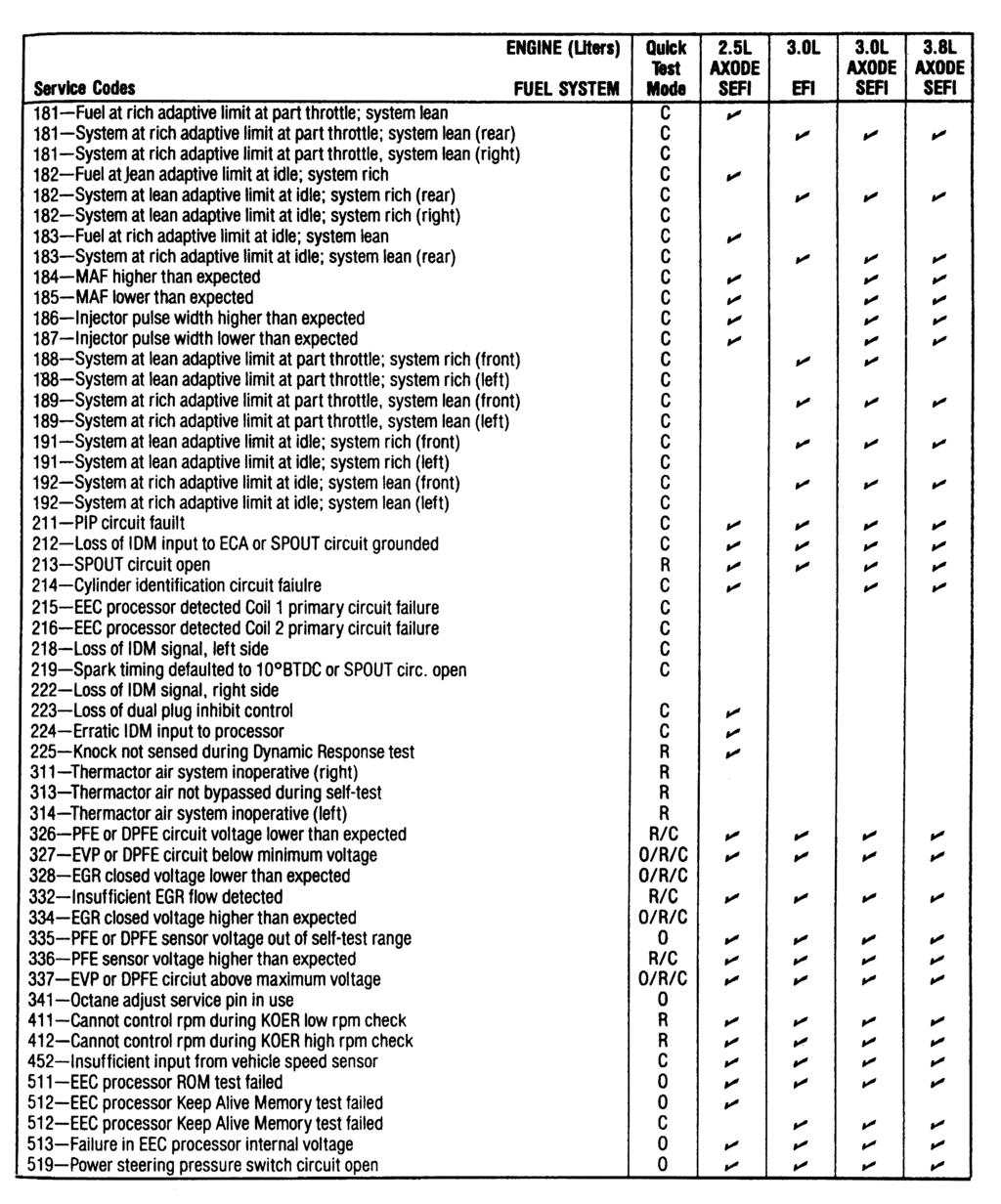
88
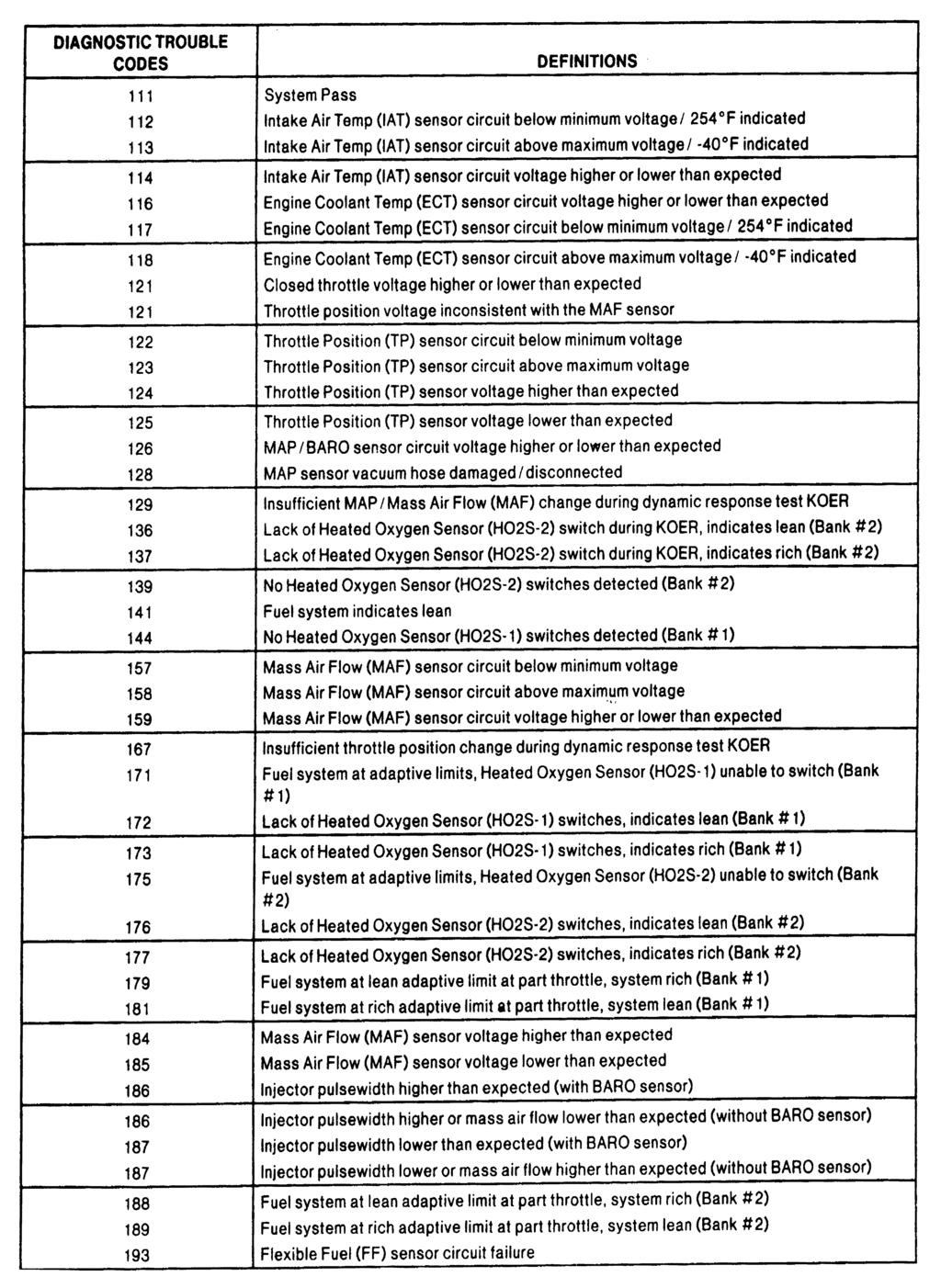
89
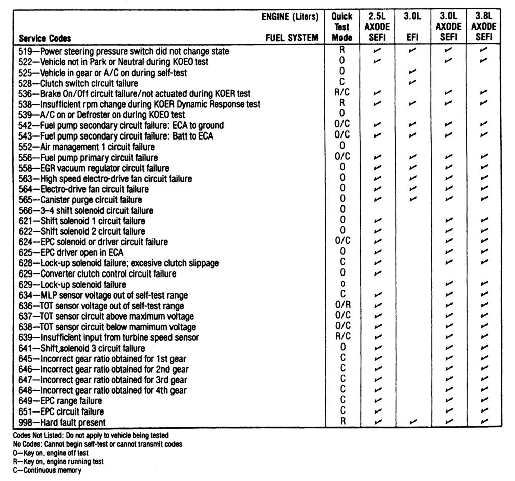
90
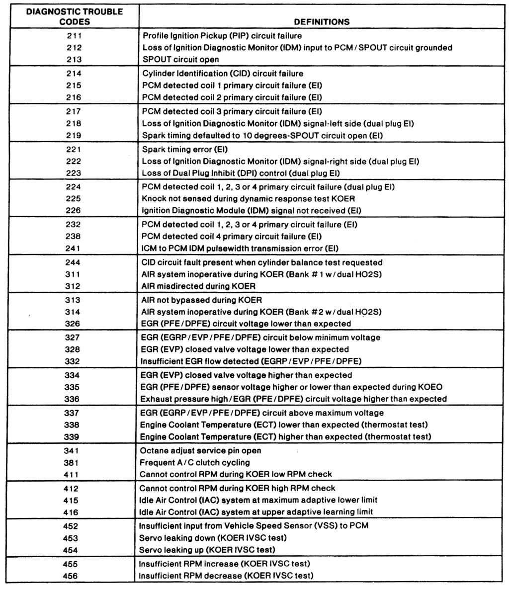
91
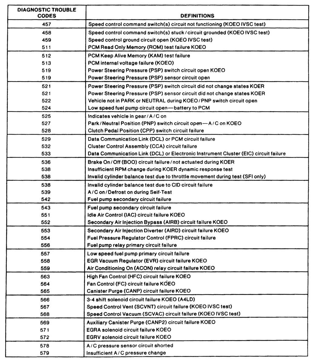
92
93
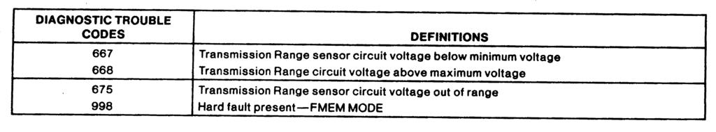
94
95
96
97
98
99
100
101
102
103
104
105
106
107
108
109
110
111
112
113
114
115
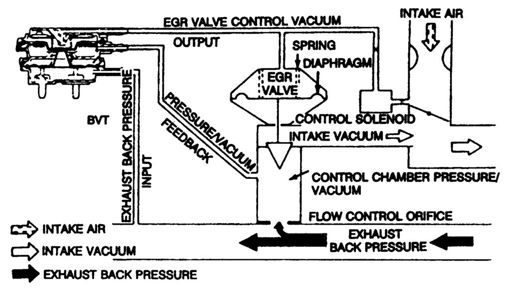
116
117
118
119
120
121
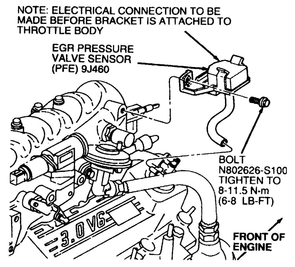
122
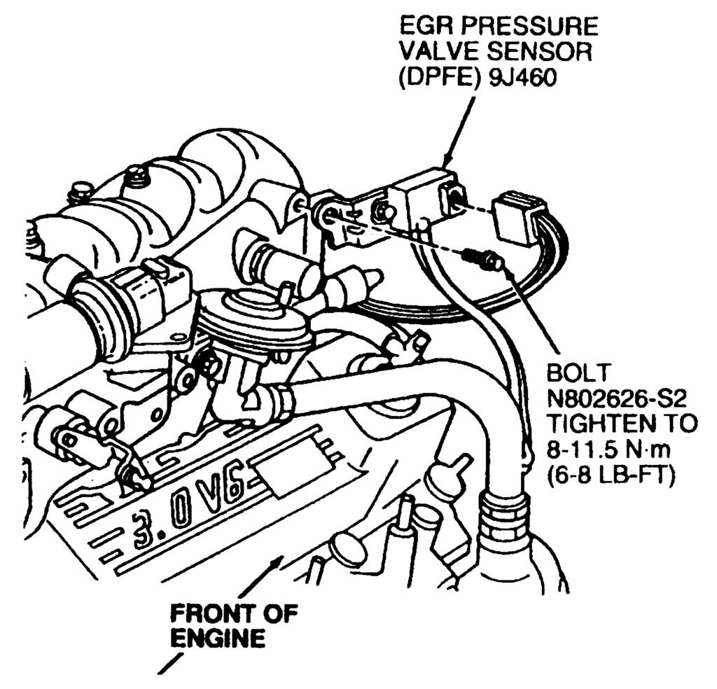
123
124
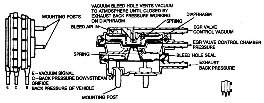
125
). The equipment that is used to limit these pollutants is commonly called emission control equipment.
. The equipment that is used to limit these pollutants is commonly called emission control equipment.") Стр. 1 из 51 EMISSION CONTROLS Introduction There are three sources of automotive pollutants: crankcase fumes, exhaust gases and gasoline evaporation. The pollutants formed from these substances can be
Стр. 1 из 51 EMISSION CONTROLS Introduction There are three sources of automotive pollutants: crankcase fumes, exhaust gases and gasoline evaporation. The pollutants formed from these substances can be
Emission from gasoline powered vehicles are classified as 1. Exhaust emission 2. Crank case emission 3. Evaporative emission. Table 1.
 Introduction: Main three types of automotive vehicle being used 1. Passenger cars powered by four stroke gasoline engines 2. Motor cycles, scooters and auto rickshaws powered mostly by small two stroke
EMISSION CONTROL VISUAL INSPECTION PROCEDURES
 EMISSION CONTROL VISUAL INSPECTION PROCEDURES 1992 Infiniti G20 1983-98 GENERAL INFORMATION Emission Control Visual Inspection Procedures All Models * PLEASE READ THIS FIRST * This article is provided
EMISSION CONTROL (AUX. EMISSION CONTROL DEVICES) H4DOTC
 H4DOTC") EMISSION CONTROL (AUX. EMISSION CONTROL DEVICES) H4DOTC SYSTEM OVERVIEW 1. System Overview There are three emission control systems, which are as follows: Crankcase emission control system Exhaust emission
EMISSION CONTROL (AUX. EMISSION CONTROL DEVICES) H4DOTC SYSTEM OVERVIEW 1. System Overview There are three emission control systems, which are as follows: Crankcase emission control system Exhaust emission
EMISSION CONTROL (AUX. EMISSION CONTROL DEVICES) H4SO
 H4SO") EMISSION CONTROL (AUX. EMISSION CONTROL DEVICES) H4SO SYSTEM OVERVIEW 1. System Overview There are three emission control systems, which are as follows: Crankcase emission control system Exhaust emission
EMISSION CONTROL (AUX. EMISSION CONTROL DEVICES) H4SO SYSTEM OVERVIEW 1. System Overview There are three emission control systems, which are as follows: Crankcase emission control system Exhaust emission
ENGINE AND EMISSION CONTROL
 -1 ENGINE CONTROL.......... GENERAL INFORMATION...... SERVICE SPECIFICATIONS..... ON-VEHICLE SERVICE......... ACCELERATOR CABLE CHECK AND ADJUSTMENT.................... ACCELERATOR CABLE AND PEDAL......................
EMISSION CONTROL (AUX. EMISSION CONTROL DEVICES) H6DO
 H6DO") EMISSION CONTROL (AUX. EMISSION CONTROL DEVICES) H6DO SYSTEM OVERVIEW 1. System Overview There are three emission control systems, which are as follows: Crankcase emission control system Exhaust emission
EMISSION CONTROL (AUX. EMISSION CONTROL DEVICES) H6DO SYSTEM OVERVIEW 1. System Overview There are three emission control systems, which are as follows: Crankcase emission control system Exhaust emission
ENGINE AND EMISSION CONTROL
 17-1 ENGINE AND EMISSION CONTROL CONTENTS ENGINE CONTROL SYSTEM........ 3 SERVICE SPECIFICATION............... 3 ON-VEHICLE SERVICE.................. 3 Accelerator Cable Check and Adjustment... 3 ACCELERATOR
HOW - TO EMISSION CONTROL BASICS EMISSION CONTROL BASICS
 HOW - TO EMISSION CONTROL BASICS EMISSION CONTROL BASICS Tool And Material Checklist Bore Brush Thermometer Portable Vacuum Pump Screwdriver Combination Wrench Set 3/8 Drive Socket Set Tachometer Rag Service
ENGINE AND EMISSION CONTROL
 17-1 GROUP 17 ENGINE AND EMISSION CONTROL CONTENTS ENGINE CONTROL........... 17-3 GENERAL INFORMATION....... 17-3 SERVICE SPECIFICATIONS..... 17-3 ON-VEHICLE SERVICE.......... 17-3 ACCELERATOR CABLE CHECK
EMISSION CONTROL EMISSION CONTROLS
 EMISSION CONTROL EMISSION CONTROLS Emissions control systems on Land Rover vehicles work closely with fuel system controls to reduce airborne pollutants. Improper operation of these systems can lead to
EMISSION CONTROL SYSTEMS
 EMISSION CONTROL SYSTEMS (3SFE) EMISSION CONTROL SYSTEMS EC1 EC2 EMISSION CONTROL SYSTEMS (3SFE) System Purpose System SYSTEM PURPOSE Abbreviation Purpose Positive crankcase ventilation Fuel evaporative
UNDERSTANDING 5 GAS DIAGNOSIS
 UNDERSTANDING 5 GAS DIAGNOSIS AND EMISSIONS Gas Diagnostic Steps This procedure will help in your efforts to figure out what the five-gas reading are telling you. In order for five gas analyses to be conclusive
EXHAUST SYSTEM AND INTAKE MANIFOLD
 EXHAUST SYSTEM AND INTAKE MANIFOLD 11-1 EXHAUST SYSTEM AND INTAKE MANIFOLD CONTENTS page GENERAL INFORMATION... 1 SERVICE PROCEDURES... 4 page TORQUE SPECIFICATION... 13 EXHAUST SYSTEMS The exhaust systems
Fuel Metering System Component Description
 1999 Chevrolet/Geo Tahoe - 4WD Fuel Metering System Component Description Purpose The function of the fuel metering system is to deliver the correct amount of fuel to the engine under all operating conditions.
Internal Combustion Engines
 Internal Combustion Engines The internal combustion engine is an engine in which the burning of a fuel occurs in a confined space called a combustion chamber. This exothermic reaction of a fuel with an
A. Perform a vacuum gauge test to determine engine condition and performance.
 ENGINE REPAIR UNIT 2: ENGINE DIAGNOSIS, REMOVAL, AND INSTALLATION LESSON 2: ENGINE DIAGNOSTIC TESTS NOTE: Testing the engine s mechanical condition is required when the cause of a problem is not located
Engine Systems. Basic Engine Operation. Firing Order. Four Stroke Cycle. Overhead Valves - OHV. Engine Design. AUMT Engine Systems 4/4/11
 Advanced Introduction Brake to Automotive Systems Diagnosis Service and Service Basic Engine Operation Engine Systems Donald Jones Brookhaven College The internal combustion process consists of: admitting
ENGINE AND EMISSION CONTROL
 17-1 GROUP 17 ENGINE AND EMISSION CONTROL CONTENTS ENGINE CONTROL.......... 17-3 GENERAL INFORMATION...... 17-3 SERVICE SPECIFICATIONS..... 17-3 TROUBLESHOOTING.......... 17-3 INTRODUCTION TO ENGINE CONTROL
WEBER CARBURETOR TROUBLESHOOTING GUIDE
 This guide is to help pinpoint problems by diagnosing engine symptoms associated with specific vehicle operating conditions. The chart will guide you step by step to help correct these problems. For successful
Module 2:Genesis and Mechanism of Formation of Engine Emissions Lecture 3: Introduction to Pollutant Formation POLLUTANT FORMATION
 Module 2:Genesis and Mechanism of Formation of Engine Emissions POLLUTANT FORMATION The Lecture Contains: Engine Emissions Typical Exhaust Emission Concentrations Emission Formation in SI Engines Emission
ENGINE AND EMISSION CONTROL
 17-1 GROUP 17 ENGINE AND EMISSION CONTROL CONTENTS ENGINE CONTROL.......... 17-3 GENERAL DESCRIPTION...... 17-3 ENGINE CONTROL SYSTEM DIAGNOSIS.................. 17-3 INTRODUCTION TO ENGINE CONTROL SYSTEM
ENGINE AND EMISSION CONTROL
 17-1 GROUP 17 ENGINE AND EMISSION CONTROL CONTENTS ENGINE CONTROL.......... 17-3 GENERAL DESCRIPTION...... 17-3 ENGINE CONTROL SYSTEM DIAGNOSIS.................. 17-3 INTRODUCTION TO ENGINE CONTROL SYSTEM
Application & Installation Guide. Crankcase Ventilation Systems LEBW
 Application & Installation Guide Crankcase Ventilation Systems LEBW4958-04 Contents Crankcase Ventilation Systems... 1 Crankcase Emissions... 2 Blow-by... 2 Crankcase Ventilation... 3 Ingestive... 3 Low
Engine Emission Control 6.7L Diesel
 Page 1 of 6 SECTION 303-08: Engine Emission Control 2011 F-250, 350, 450, 550 Super Duty Workshop Manual DESCRIPTION AND OPERATION Procedure revision date: 03/12/2010 Engine Emission Control 6.7L Diesel
Module 5: Emission Control for SI Engines Lecture20:ADD-ON SYSTEMS FOR CONTROL OF ENGINE-OUT EMISSIONS
 ADD-ON SYSTEMS FOR CONTROL OF ENGINE-OUT EMISSIONS The Lecture Contains: Crankcase Emission Control (PCV System) Evaporative Emission Control Exhaust Gas Recirculation Water Injection file:///c /...%20and%20Settings/iitkrana1/My%20Documents/Google%20Talk%20Received%20Files/engine_combustion/lecture20/20_1.htm[6/15/2012
Fuel and exhaust systems 4A 21
 Fuel and exhaust systems 4A 21 15.40 Unscrew the union nuts and disconnect the fuel feed and return hoses from the manifold 41 Disconnect the injector wiring harness connector and the vacuum hose from
Chapter 4 ANALYTICAL WORK: COMBUSTION MODELING
 a 4.3.4 Effect of various parameters on combustion in IC engines: Compression ratio: A higher compression ratio increases the pressure and temperature of the working mixture which reduce the initial preparation
COMBUSTION CHEMISTRY & EMISSION ANALYSIS
 Section 3 COMBUSTION CHEMISTRY & EMISSION ANALYSIS Introduction to Combustion Chemistry The gasoline powered internal combustion engine takes air from the atmosphere and gasoline, a hydrocarbon fuel, and
Honda Accord/Prelude
 Honda Accord/Prelude 1984-1995 In Tank Fuel Pumps TEST 1. Turn the ignition OFF. 2. On the Accord, remove the screws securing the underdash fuse box to its mount. Remove the fuel cut off relay from the
E - THEORY/OPERATION - TURBO
 E - THEORY/OPERATION - TURBO 1995 Volvo 850 1995 ENGINE PERFORMANCE Volvo - Theory & Operation 850 - Turbo INTRODUCTION This article covers basic description and operation of engine performance-related
Air Management System Components
 AIR M anagement Sys tem Air Management System Components Air Management System Features Series Sequential The series sequential turbocharger is a low pressure/high pressure design working in series with
Chapter 4 Part D: Exhaust and emission control systems
 4D 1 Chapter 4 Part D: Exhaust and emission control systems Contents Air inlet heating system components - removal and refitting...... 4 Catalytic converter - general information and precautions........
Exhaust System - 2.2L Diesel
 Page 1 of 9 Published: Mar 8, 2007 Exhaust System - 2.2L Diesel COMPONENT LOCATION - WITH DIESEL PARTICULATE FILTER Item Part Number Description 1 Exhaust manifold (ref only) 2 Pressure differential sensor
Chapter 4 Part D: Fuel and exhaust systems - Magneti Marelli injection
 4D 1 Chapter 4 Part D: Fuel and exhaust systems - Magneti Marelli injection Contents Accelerator cable - removal and..................... 11 Air cleaner element - renewal..............................
Chapter 4 Part C: Emissions control systems
 Chapter 4 Part C: Emissions control systems Contents Catalytic converter - general information and precautions........ 9 Crankcase emissions control system - testing and renewal....... 2 Exhaust emissions
Looking ahead to tier 4
 Looking ahead to tier 4 Donora, PA For five days, a cloud of air pollution overtakes the industrial town of Donora, Pennsylvania, sickening 40% of the town. 20 die. 194 8 Where does tier 4 come from? All
Unit D: Agricultural Equipment Systems. Lesson 1: Understanding Applications of Fluids and Lubricants in Agricultural Equipment
 Unit D: Agricultural Equipment Systems Lesson 1: Understanding Applications of Fluids and Lubricants in Agricultural Equipment 1 Terms Ash content bottom dead center cloud point compression ratio coolant
Module 3: Influence of Engine Design and Operating Parameters on Emissions Lecture 14:Effect of SI Engine Design and Operating Variables on Emissions
 Module 3: Influence of Engine Design and Operating Parameters on Emissions Effect of SI Engine Design and Operating Variables on Emissions The Lecture Contains: SI Engine Variables and Emissions Compression
1988 Ford F-350 PICKUP
 1988 Ford F-350 PICKUP Submodel: Engine Type: V8 Liters: 7.5 Fuel Delivery: FI Fuel: GAS 1987 93 4.9L Engine The intake and exhaust manifolds on these engines are known as combination manifolds and are
PERFORMANCE AND EMISSION ANALYSIS OF DIESEL ENGINE BY INJECTING DIETHYL ETHER WITH AND WITHOUT EGR USING DPF
 PERFORMANCE AND EMISSION ANALYSIS OF DIESEL ENGINE BY INJECTING DIETHYL ETHER WITH AND WITHOUT EGR USING DPF PROJECT REFERENCE NO. : 37S1036 COLLEGE BRANCH GUIDES : KS INSTITUTE OF TECHNOLOGY, BANGALORE
ACCELERATOR CABLE AND PEDAL
 17 ENGINE & EMISSION CONTROL 1996 Engine Control System ACCELERATOR CABLE AND PEDAL REMOVAL AND INSTALLATION Post-installation Operation (Refer to Adjusting the Accelerator Cable.)
Exhaust After-Treatment System. This information covers design and function of the Exhaust After-Treatment System (EATS) on the Volvo D16F engine.
 on the Volvo D16F engine.") Volvo Trucks North America Greensboro, NC USA DService Bulletin Trucks Date Group No. Page 1.2007 258 44 1(6) Exhaust After-Treatment System Design and Function D16F Exhaust After-Treatment System W2005772
Volvo Trucks North America Greensboro, NC USA DService Bulletin Trucks Date Group No. Page 1.2007 258 44 1(6) Exhaust After-Treatment System Design and Function D16F Exhaust After-Treatment System W2005772
THE FOURTH STATE. Gaining a universal insight into the diagnosis of automotive ignition systems. By: Bernie Thompson
 THE FOURTH STATE Gaining a universal insight into the diagnosis of automotive ignition systems By: Bernie Thompson Did you know that the forth state of matter powers the spark ignition internal combustion
Learning Guide EMISSION SPECIALIST 5 GAS ANALYSIS COURSE NUMBER: E001-01
 Learning Guide EMISSION SPECIALIST 5 GAS ANALYSIS COURSE NUMBER: E001-01 Notice Due to the wide range of vehicles makes and models, the information given during the class will be general in nature and
CEE 452/652. Week 6, Lecture 1 Mobile Sources. Dr. Dave DuBois Division of Atmospheric Sciences, Desert Research Institute
 CEE 452/652 Week 6, Lecture 1 Mobile Sources Dr. Dave DuBois Division of Atmospheric Sciences, Desert Research Institute Today s topics Read chapter 18 Review of urban atmospheric chemistry What are mobile
2005 Escape Workshop Manual Cylinder block
 22 6010 Cylinder block Cylinder Head Item Part Number Description 1 12A366 Coil-on-plug assembly (4 req'd) 2 6M293 Valve cover 3 12K073 Camshaft position (CMP) sensor 4 6766 Oil filler cap 5 6M293 Valve
Name Date. True-False. Multiple Choice
 Name Date True-False T F 1. Oil film thickness increases with an increase in oil temperature. T F 2. Displacement is the volume that a piston displaces in an engine when it travels from top dead center
AN EXPLANATION OF CIRCUITS CARTER YH HORIZONTAL CLIMATIC CONTROL CARBURETER
 AN EXPLANATION OF CIRCUITS CARTER YH HORIZONTAL CLIMATIC CONTROL CARBURETER The Carter Model YH carbureter may be compared with a Carter YF downdraft carbureter with the circuits rearranged to operate
EMISSION CONTROL SYSTEMS (2JZ GE) SYSTEM PURPOSE
 SYSTEM PURPOSE") SYSTEM PURPOSE The emission control systems are installed to reduce the amount of CO, HC and NOx exhausted from the engine ((3), (4) and (5)), to prevent the atmospheric release of blowby gascontaining
SYSTEM PURPOSE The emission control systems are installed to reduce the amount of CO, HC and NOx exhausted from the engine ((3), (4) and (5)), to prevent the atmospheric release of blowby gascontaining
EVERY ALTERNATIVE ISLG Combustion Air and Emission Devices. Why Cooled EGR? 4/23/2013. Why Exhaust Gas Recirculation.
 EVERY ALTERNATIVE. 2007 ISLG Combustion Air and Emission Devices Why Exhaust Gas Recirculation Basic Science NOx (Oxides of Nitrogen) pollution occurs due to high cylinder temperatures during the combustion
13. FUEL SYSTEM/CARBURETOR/
 13 FUEL SYSTEM/CARBURETOR/FUEL PUMP FUEL SYSTEM --------------------------------------------------------- 13-1 SCHEMATIC DRAWING ---------------------------------------------- 13-2 OPERATION OF CARBURETOR
Technical Support Note
 Title: Measuring Emissions from Diesel-Fueled Equipment TSN Number: 09 File:S:\Bridge_Analyzers\Customer_Service_Documentation\Technical_Support_Notes\ 09_Measuring_Emissions_from_Diesel_Fuel_Equipment.docx
The Need for Alternative Fuel Sources: Biodiesel and Other Options. Jill Burrows 11/21/05
 The Need for Alternative Fuel Sources: Biodiesel and Other Options Jill Burrows 11/21/05 Diesel Engines 94% of all goods in the Unites States are transported by vehicles with diesel powered engines Used
SECTION 3.00 WARNING WARNING ENGINE STARTUP AND SHUTDOWN PRESTART INSPECTION
 SECTION 3.00 ENGINE STARTUP AND SHUTDOWN PRESTART INSPECTION Be sure that the clutch, circuit breaker, or other main power transmission device is disconnected. Generators develop voltage as soon as the
Section 10 Chapter 7
 Section 10 Chapter 7 24 Valve, 8.3 Liter Engine Troubleshooting Symptoms Identification Note: All coding used in the 8.3 Liter and 9 Liter engine manuals are Cummins engine codes. These engine codes have
ELECTRONIC FUEL INJECTION (EFI)
") Стр. 1 из 31 ELECTRONIC FUEL INJECTION (EFI) General Description The Electronic Fuel Injection (EFI) system was used on 1991 2.5L, 1986-92 3.0L (except SHO) and 1988-92 3.8L engines. The EFI fuel system
Стр. 1 из 31 ELECTRONIC FUEL INJECTION (EFI) General Description The Electronic Fuel Injection (EFI) system was used on 1991 2.5L, 1986-92 3.0L (except SHO) and 1988-92 3.8L engines. The EFI fuel system
Catalytic Failures. Engine running too hot.
 Catalytic Failures It is not uncommon for technicians to misdiagnose a driveability or emissions issue by blaming the converter. In many cases, it s not the converter s fault, but rather one of the engine
Water pump Owner's Manual
 Water pump Owner's Manual Safety Precautions I. General Safeguards Please read this operation manual to have a thorough understanding of the content there before use the product. Failure to do so may lead
PRODUCT INFORMATION SHEET
 Page 1 of 18 31592 WYNN S DPF Cleaner & Regenerator WYNN S Diesel Particulate Filter Cleaner & Regenerator Product Number: 31592 12 x 325ml New technologies to reduce emissions with diesel engines The
4.0L CEC SYSTEM Jeep Cherokee DESCRIPTION OPERATION FUEL CONTROL DATA SENSORS & SWITCHES
 4.0L CEC SYSTEM 1988 Jeep Cherokee 1988 COMPUTERIZED ENGINE Controls ENGINE CONTROL SYSTEM JEEP 4.0L MPFI 6-CYLINDER Cherokee, Comanche & Wagoneer DESCRIPTION The 4.0L engine control system controls engine
FUEL SYSTEM/CARBURETOR/FUEL PUMP
 13 FUEL SYSTEM/CARBURETOR/FUEL PUMP FUEL SYSTEM-------------------------------------------------------------------------------------13-1 SCHEMATIC DRAWING-------------------------------------------------------------------------13-2
Powertrain Efficiency Technologies. Turbochargers
 Powertrain Efficiency Technologies Turbochargers Turbochargers increasingly are being used by automakers to make it possible to use downsized gasoline engines that consume less fuel but still deliver the
Q1.This question is about the temperature of the Earth s atmosphere. Give one reason why it is difficult to produce models for future climate change.
 Q1.This question is about the temperature of the Earth s atmosphere. (a) Give one reason why it is difficult to produce models for future climate change..... (b) Describe how carbon dioxide helps to maintain
5. FUEL SYSTEM 5-0 FUEL SYSTEM UXV 500
 5 FUEL SYSTEM 5 SERVICE INFORMATION------------------------------------------------ 5-02 TROUBLESHOOTING----------------------------------------------------- 5-03 FUEL TANK -----------------------------------------------------------------
GENERAL SERVICE INFORMATION
 GENERAL SERVICE INFORMATION Component Identification Figure 31 Reference Description Number 1 Lifting Eye (Flywheel End) 2 Turbocharger* 3 Lifting Eye ( Cooling Fan End) 4 Coolant Pump 5 Cooling Fan 6
ENGINE AND EMISSION CONTROL
 17-1 GROUP 17 ENGINE AND EMISSION CONTROL CONTENTS ENGINE CONTROL 17-2 GENERAL INFORMATION 17-2 AUTO-CRUISE CONTROL SYSTEM 17-3 GENERAL INFORMATION 17-3 CONSTRUCTION AND OPERATION 17-5 17-7 GENERAL INFORMATION
ME 74 AUTOMOTIVE POLLUTION AND CONTROL Automobile Engineering-vii sem Question Bank( )
") ME 74 AUTOMOTIVE POLLUTION AND CONTROL Automobile Engineering-vii sem Question Bank(2013-2014) UNIT I INTRODUCTION 1. How the transient operation of S.I engine will cause CO formation? (may /June 2007)
ME 74 AUTOMOTIVE POLLUTION AND CONTROL Automobile Engineering-vii sem Question Bank(2013-2014) UNIT I INTRODUCTION 1. How the transient operation of S.I engine will cause CO formation? (may /June 2007)
 Page 1 of 18 2004 PCED On Board Diagnostics SECTION 5: Pinpoint Tests Procedure revision date: 10/26/2007 H: Fuel Control H: Introduction H1 PERFORM THE KOER SELF-TEST Engine at normal operating temperature.
Engine Exhaust Emissions
 Engine Exhaust Emissions 1 Exhaust Emission Control Particulates (very challenging) Chamber symmetry and shape Injection characteristics (mixing rates) Oil control Catalyst (soluble fraction) Particulate
2015 PSI 8.8L LPG Engine Overview. Study Guide. Course Code: 8777
 2015 PSI 8.8L LPG Engine Overview Study Guide Course Code: 8777 1 2015 PSI 8.8L LPG Engine Overview Study Guide 2015 Navistar, Inc. 2701 Navistar Drive, Lisle, IL 60532. All rights reserved. No part of
Combustion process Emission cleaning Fuel distribution Glow plugs Injectors Low and high pressure pumps
 Page 1 of 16 S60 (-09), 2004, D5244T, M56, L.H.D, YV1RS799242356771, 356771 22/1/2014 PRINT Combustion process Emission cleaning Fuel distribution Glow plugs Injectors Low and high pressure pumps Fuel
Evaporative Emissions
 Page 1 of 6 Published : Apr 8, 2005 Evaporative Emissions 4.4L V8 Evaporative Emissions Component Layout Item Part Number 1 - Fuel filler head 2 - DMTL pump filter (NAS only) 3 - Fuel tank vent hose to
Module 4: Climate Control
 ÂÂ ÂÂ Air-Conditioning Electronic Control Unit (ECU) Â Controlling Cabin Air Temperature Servo Motors Electric Servo Motors ÂÂ Air-Conditioning Electronic Control Unit (ECU) Automatic Climate Control Sensors
FOR EVERYONE. and new-source performance standards that strictly regulated emissions of a new source (e.g., automobiles, factories) entering an area.
 entering an area.") CLEANER AIR FOR EVERYONE AN EVOLUTION OF CLEAN AIR IN NORTH AMERICA AND PART1HOW ENGINE EMISSION REGULATIONS AFFECT YOU One thing is clear the air we breathe is getting cleaner, thanks to years of work
CLEANER AIR FOR EVERYONE AN EVOLUTION OF CLEAN AIR IN NORTH AMERICA AND PART1HOW ENGINE EMISSION REGULATIONS AFFECT YOU One thing is clear the air we breathe is getting cleaner, thanks to years of work
SVX +++ EMISSION CONTROL SYSTEM AND VACUUM FITTING 2-1 SUBARU
 EMSSON CONTROL SYSTEM AND VACUUM FTTNG 2-1 SUBARU SVX 1992 Page 1. System Application......................................................... 2 2. Schematic Drawing..........................................................
Carburetor Instructions
 Carburetor Instructions for HUDSON SUPER SIX ESSEX SIX CYLINDER Hudson Motor Car Co. DETROIT, U.S.A. Carburetor The carburetor is a device for metering correct amounts of fuel and air for the various
TC Series Cooling Systems
 TC Series Cooling Systems Table of Contents Table of Contents...1 List of Figures...1 Safety...2 Introduction...2 General Specifications...2 Types of Coolant...2 Routine Maintenance...2 Surge Tank Coolant
ENGINE TECHNOLOGY. Bobcat Engine_B _ _EN_reworked.indd 1
 ENGINE TECHNOLOGY Bobcat Engine_B4459500_01-2015_EN_reworked.indd 1 1/30/2015 10:07:51 AM A COMPANY THAT S GROWING WITH SOCIETY Bobcat prides itself on innovations that shape the future. For decades, we
AIR CLEANER GENERAL REMOVAL. 1CAUTION Do not run engine without filter element in place. Debris could be drawn into the engine causing damage.
 AIR CLEANER GENERAL The air cleaner prevents foreign material from entering the carburetor and engine by trapping airborne dust and dirt in the filter element. Service air cleaner filter element every
Typical Install Instructions
 Typical Install Instructions Read & understand all steps of these instructions before beginning this installation. WEBER Conversion Kit, VW T-1/2, up to 1835cc 32 / 36 DFEV Weber Carburetor These instructions
IMPORTANT SAFETY INSTRUCTIONS
 ASSOCIATED Model 6039 Battery Tester Operator's Manual IMPORTANT SAFETY INSTRUCTIONS 1. SAVE THESE INSTRUCTIONS This manual contains important safety and operating instructions for the battery tester you
Module 2:Genesis and Mechanism of Formation of Engine Emissions Lecture 9:Mechanisms of HC Formation in SI Engines... contd.
 Mechanisms of HC Formation in SI Engines... contd. The Lecture Contains: HC from Lubricating Oil Film Combustion Chamber Deposits HC Mixture Quality and In-Cylinder Liquid Fuel HC from Misfired Combustion
ENGINE 6G74 3.5L-SOHC-24 VALVE
 11A ENGINE General Information/Service Specifications ENGINE 6G74 3.5L-SOHC-24 VALVE GENERAL INFORMATION Items Specifications Type V-type, Over Head Camshaft Number of cylinders 6 Bore mm 93.0 Stroke mm
Fuel Wize works with engine oil as well.
 Fuel Wize works with engine oil as well. It first functions as a soap/solvent which cleans the walls of the cylinder while removing many of impurities and residues in the oil. Second, Fuel Wize actually
Module7:Advanced Combustion Systems and Alternative Powerplants Lecture 32:Stratified Charge Engines
 ADVANCED COMBUSTION SYSTEMS AND ALTERNATIVE POWERPLANTS The Lecture Contains: DIRECT INJECTION STRATIFIED CHARGE (DISC) ENGINES Historical Overview Potential Advantages of DISC Engines DISC Engine Combustion
There are predominantly two reasons for excessive fuelling: increased fuel pressure and extended injector duration. Figure 1.0
 In this tutorial we look at the actuators and components that affect the vehicles exhaust emissions when the electronically controlled fuel injection system is found to be over fuelling. There are predominantly
Cooling System. Table of Contents
 Sub-Headings Safety 2 s 2 Cautions 2 Notes 2 Introduction 2 General Specifications 2 Engine 2 Coolant 2 Routine Maintenance 2 Hose Connections 4 Radiator, Charge Air and Heater Cores 4 Cooling System Leaks
26 - COOLING SYSTEM CONTENTS ENGINE COOLING - DESCRIPTION... 3 ENGINE COOLING - OPERATION... 9 COOLING SYSTEM FAULTS... 1
 26 - COOLING SYSTEM CONTENTS Page LAND ROVER V8 DESCRIPTION AND OPERATION ENGINE COOLING - DESCRIPTION... 3 ENGINE COOLING - OPERATION... 9 FAULT DIAGNOSIS COOLING SYSTEM FAULTS... 1 REPAIR COOLANT - DRAIN
2013 Aftertreatment System with SCR Overview for Technicians Study Guide
 TMT121340 Class Course Code: 8359 2013 Aftertreatment System with SCR Overview for Technicians Study Guide 2013 Aftertreatment System with SCR Study Guide 2013 Navistar, Inc. All rights reserved. All marks
insider info. before it can be inspected for proper emissions. Misfire, Fuel System and Component
 insider info. Rough Idle On MPFI Vehicles If you encounter a rough idle complaint on any sequential injection MPFI vehicle, basic checks should be made to ensure that the correct injector wire connector
Section 10 Chapter 17
 Section 10 Chapter 17 24 Valve, 8.3 Liter Engine Air Intake System Note: All coding used in the 8.3 Liter and 9 Liter engine manuals are Cummins engine codes. These engine codes have no meaning to New
TROUBLESHOOTING
 174501 053 1. TROUBLESHOOTING 054 2. LAYOUT 1. Exhaust Manifold Assy 2. Exhaust Manifold Gasket 3. Hex Flange Nut 4. Heat Protector Assy 5. Hex Bolt (M6 X 1 X 25) 6. Heat Protector Assy 7. Hex Bolt (M8
2007 Emissions: Fundamentals
 A N AV I S TA R C O M PA N Y 2007 Emissions: Fundamentals Study Guide TMT-100718 Study Guide 2007 Emissions: Fundamentals TMT-100718 2007 International Truck and Engine Corporation 4201 Winfield Road,
SPECIFICATIONS 4.1 ITEM TORQUE NOTES. Air Cleaner Cover Screws in-lbs Nm LOCTITE THREADLOCKER 222 (purple), page 4-21
, page 4-21") 4 SPECIFICATIONS 4.1 CARBURETOR JET SIZES CARBURETOR ADJUSTMENTS Main Jet 195 Slow Jet 42 FUEL TANK CAPACITY GALLONS LITERS Total (including reserve) 5.0 18.93 Reserve 0.6 2.2 Engine Fast Idle Speed (using
4 SPECIFICATIONS 4.1 CARBURETOR JET SIZES CARBURETOR ADJUSTMENTS Main Jet 195 Slow Jet 42 FUEL TANK CAPACITY GALLONS LITERS Total (including reserve) 5.0 18.93 Reserve 0.6 2.2 Engine Fast Idle Speed (using
CHAPTER 1 INTRODUCTION
 1 CHAPTER 1 INTRODUCTION 1.1 GENERAL Diesel engines are the primary power source of vehicles used in heavy duty applications. The heavy duty engine includes buses, large trucks, and off-highway construction
5. Control System CONTROL SYSTEM FUEL INJECTION (FUEL SYSTEM) A: GENERAL FU(H4DOTC)-29
 A: GENERAL FU(H4DOTC)-29") W1860BE.book Page 29 Tuesday, January 28, 2003 11:01 PM 5. Control System A: GENERAL The ECM receives signals from various sensors, switches, and other control modules. Using these signals, it determines
W1860BE.book Page 29 Tuesday, January 28, 2003 11:01 PM 5. Control System A: GENERAL The ECM receives signals from various sensors, switches, and other control modules. Using these signals, it determines
by Jim Phillips, P. E.
 by Jim Phillips, P. E. Baking flour, coal dust and gasoline; what do these things have in common? They are not the ingredients for a strange new cake recipe. Each of these ingredients is the fuel that
Retrofit Crankcase Ventilation for Diesel Engines
 mdec Mining Diesel Emissions Conference Toronto Airport Marriott Hotel, October 7-9th, 2014 Retrofit Crankcase Ventilation for Diesel Engines John Stekar, Catalytic Exhaust Products Diesel Engine Crankcase
Presented by. Navistar Education 2015
 Presented by Navistar Education 2015 1.2 Overview This course is intended to provide parts specialists with a description of Diesel Exhaust Fluid, or DEF, part number configuration, ordering and distribution