Introduction. What is new and different?
|
|
|
- Conrad Dickerson
- 6 years ago
- Views:
Transcription
1


2 Introduction ValveExpert was developed for testing servo- and proportional valves using advanced computer technology. Any 4-way flow control valves with flow up to 80 L/min and pressure up to 210 bar can be tested. The tests are performed quickly and with low energy usage. Graphic on-screen assistance guides the user through the entire testing procedure. The test results can then be saved to file and printed out as well. What is new and different? Older, traditional test equipment usually had to be connected to an existing hydraulic power supply, and required power of 40 kw for testing a servovalve with a nominal flow of 80 L/min and a pressure of 210 bar. All this power for testing was lost and converted into heat and cooling by either be strong ventilation or complex water-cooling was necessary. This is quite different with the ValveExpert technology. The valve characteristics are captured in fast mode. For this short test process, the energy is taken out of an accumulator. An installed power supply of 6 kw is sufficient where often 40 kw was necessary. Due to the short testing time, only little energy will be converted to heat and additional cooling is not necessary. Also, because a small oil tank is sufficient, the entire hydraulic power supply is small enough to be built into the test stand. If you need to test servo- or proportional valves; the ValveExpert test-rig offers you the functionality of a full laboratory in a small space and at lowest cost.

3 Features Plug and Play The user simply switches on the electric power and mounts the servovalve to be tested. Then, a few minutes after starting the test sequence, the test results are available for printing or saving to file. Mobility The hydraulic power supply is built into the test rig itself and therefore no external piping is required. And since cooling is not necessary, no water connection is required either. Consequently, the test stand can easily be moved and installed at different places. Fully automatic test Besides being able to manually test valves, the operator can perform a fully automatic test by simply entering the model number of the valve to be tested and pushing the run button Only few minutes later 3 to 4 pages of test results are available, that can be saved to file or printed out. No skills The user is guided through the testing sequence by graphic displays. No sophisticated skills are required. The operator is only required to have basic knowledge on how to use a computer running Windows, as well as the knowledge on how a servovalve works. Efficiency Because of the closed-loop pressure control on the hydraulic pump, the test stand uses no more energy than absolutely necessary. An electric motor drives a pump with fixed displacement and high efficiency. When the servovalve is without flow, the motor rotates economically slowly. As only little energy is converted into heat, cooling is not necessary. Silent The pump is the most silent gear pump on the world market, the supplier of this pump claims. We believed it and then installed it into the oil tank for even less noise! Reliability The gear pump is oversized in its pressure rating and usually works at medium pressure in short cycles. Further, the oil is very clean - as required for the servovalves - and pump wear is minimal. The electric servo motor is brushless and does not require any maintenance. The switching valves, transducers and filters are mounted on a manifold. Having only a few fittings greatly decreases the probability of any leakage. Low cost Simple installation: Plug in to the three phase network. That's it. Small footprint Thanks to the smart pressure-control loop and a short test time, energy costs are minimal. ValveExpert is a low-cost device.

4 Measurement Principle One of the outstanding features of this test rig is its integrated hydraulic power supply. The question then arises: How is it possible to generate a flow up to 80 l/min with such a small device? The answer is that the flow is measured rapidly; the necessary energy is taken out of the large accumulator. However, the resulting flow curve will be virtually blown up by a dynamic effect because the valve spool cannot move as quickly as the valve control signal is commanding it to move. This dynamic effect is then eliminated by applying an advanced mathematical algorithm to correct the phase lag between the in and output signals. This procedure is demonstrated in the two diagrams given below. This diagram shows the flow curve of a REXROTH proportional valve. This valve is equipped with a ramp function. The ramp objective is to slow down the command signal of the valve, which therefore has an intentionally slower dynamic response. As can be seen, the curve is blown up and it is difficult to recognize the hysteresis, the overlap or the curvilinear form of the valve. (The curve was sampled with a control signal of 25% of the nominal signal and a frequency of 0,01 Hz.) After the dynamic correction, we obtain the new diagram. Now it can be seen that the valve has no hysteresis, which was to be expected because of the valves closed-loop position control of the spool. Moreover, the overlap and form of the flow-curve can be seen clearly. An additional advantage of this method is that the valve can be tested without changing the adjusted ramp. Indeed, such a ramp is usually optimized for a specific application and after testing the adjustment does not have to be repeated.

5 Hydraulics Brushless servomotor and internal gear pump A brushless servomotor drives an internal gear pump which is mounted inside the oil tank. The internal gear ring of the pump is supported by a hydrodynamic/hydrostatic lubricating film, which allows operating at low and high speeds. The servomotor, which operates in a closedloop velocity mode, superimposes a closed-loop pressure control that regulates the system pressure of the test rig. The pressure gauge of this loop is mounted close to the pressure port of the valve to be tested. As soon as the pressure is reached, the servomotor slows down and rotates just enough slowly to compensate the leakage flow. With closed load ports, there is no noise. A red lamp has been installed to indicate the presence of high pressure. Even with flow the pump has a low noise level and it has been installed inside the oil tank for additional insulation. As watercooling is unnecessary, the test rig could even be installed in an office environment without causing any major disturbances. Filter The larger filter with a 3-micron high-pressure element does the main oil-cleaning job. An additional last chance filter with a 12-micron high-pressure element is installed in-line and at the pressure port of the valve to be tested. Hydraulic distribution manifold All control valves, pressure gauges, the flow meter and the filters are mounted on a single manifold requiring only a minimum of pipes and fittings to be used and thereby greatly reducing the probability of any external leakage. Maintenance and survey All maintenance work on the hydraulic equipment can be performed from one side of the test rig as shown in the picture, and all elements are easily accessible to allow verification of the oil level, the accumulator pressure and loading, verification of various pressures via miniature fittings, and exchange of the filter units. Accumulator A large piston accumulator with a capacity of 6 litres and a preload pressure of 35 bars provides the test rig with the necessary energy when flow peaks are demanded. Oil tank The oil tank has a capacity of 40 litres. While using the test rig under normal conditions, the oil temperature will increase from ambient temperature to an average value of 40 C. When using the test rig very intensively (in a production line), the temperature may rise further and on reaching 60 C the test stand will be automatically stopped until the temperature declines again. We recommend using hydraulic oil with flat viscosity characteristics (for example Shell Tellus Arctic). As the useful flow of servovalves is turbulent, the influence of temperature on flow measurements is negligible and on leakage flow measurements, the temperature has only little effect.

6 Electronics SMD technology Using surface mounted technology enabled the small size of the electronics, which are mounted in a Plastic housing. The cover of the housing is made of transparent Plexiglass so the LEDs, which show the status of the various functions of the test process, can easily be seen. Connectors All the connectors and cables to measurement and signal processing devices are shielded. A 100-pin connector assures a high and reliable data transfer rate to the computer. Relays The different configurations for the servovalve control signal for series, parallel or individual configuration are realized with relay switches. This feature saves the operator time, as only one single cable is required and the desired connections are selected by a simple mouse click. Current amplifier The current amplifier for the servovalve control signal can supply an output current of 500mA and is mounted on a generously dimensioned radiator, which, but for safety purposes the output current is limited to 120 ma. LED indicators All the important states of the test rig, such as the state of the valves, functionality of filters and power supplies, the oil level, the pulses from the flow-meter, the positive or negative servovalve control signal, the relay configurations, etc. are indicated by LEDs. This allows easy trouble shooting in case of a malfunction. Programmable circuitry ALTERA All digital circuits are implemented on a programmable chip, Altera, which allows modifying the digital circuits simply by programming with an external connector which has been provided for.
 Four simulated manometers (which therefore cannot leak and cannot be destroyed by hydraulic shocks) can be individually changed to a different scale (250 bar, 100 bar or 20 bar), or even to")

 Oil-temperature gauge: analogue and digital. Accumulator charge level display. Switch or direction valve control by mouse click.")
7 Manual test When the test-stand is in the manual test mode, you virtually have a full laboratory at your disposal: (See the picture of the 19 screen in manual mode below.) Four simulated manometers (which therefore cannot leak and cannot be destroyed by hydraulic shocks) can be individually changed to a different scale (250 bar, 100 bar or 20 bar), or even to different units as psi or Pa. By clicking on the manometer the actual pressure value is displayed in numerical format for several seconds. A simulated instrument for flow measurement, which can also be configured to have a different sensitivity or display different units as L/min, cis or gal/min simply by clicking. Two volt/ampere meters; one for the servovalve control signal and the other for the spool position signal of valves with electric feedback. (Click feature for numerical readout.) Oil-temperature gauge: analogue and digital. Accumulator charge level display. Switch or direction valve control by mouse click. The control panel allows setting the system pressure and the servovalve control signal either analogue via potentiometer or numerically by keyboard. Selection of the servovalve connection configuration for series, parallel or individual configuration. Selection of the sensitivity of the servovalve spool position signal. Particular attention should be paid to Feedback control. The adjustment of the null position of servovalves with conventional test equipment is often difficult. Not so with ValveExpert: by clicking on Feedback, the servovalve being tested, automatically searches its hydraulic null in a closed-loop mode. Now, the null position can be adjusted to zero control signal or to any other predefined value while the feedback function keeps the servovalve at hydraulic null. In the menu Settings, the desired units can be defined. The sensitivity can be freely defined by clicking on any of the measurement instruments.


8 Automatic test The Database Servovalve test specifications are stored in a database which is similar in function to the Windows Explorer. The test specifications for newer servo- or proportional valves can be retrieved by simply entering the valve label, or if the specifications are not in the database, the user can supply these parameters by entering the information from the product catalogue of the valve supplier in the database configuration page. The test rig is equipped with only one flow meter that is located in the pressure line of the servovalve under test. Consequently, the servovalve pressure drop equals the system pressure. As the measurement principle is to take a greater part of the energy out of an accumulator, which has a preload of 35 bars, tests can only be performed above system pressure of 40 bars. It is recommended to test the valves with a pressure of 70 bars (or 1000 psi), which is the nominal pressure drop of most servovalves. Program for fully automatic test After starting the fully automatic test program, the operator enters the model number of the valve to be tested, the valve serial number, the customer name and his own name. Then the operator has the option of choosing various test modes, for example the static test without flow testing or the dynamic test, etc. After issuing the Test command, the test proceeds automatically, and after a couple of minutes the program finishes and the operator can analyse the test results. Now the operator has various options of analyses and can define whether he wants the dynamic correction, the evaluation of pressure gain, flow linearity, etc. But more importantly, he can still define what units he wants the results to be in: l/min, cis, gal/min, bar, psi, Pa,etc. One of the main features is that the test results can be saved to file and retrieved at any time, and then be evaluated in the desired units. In addition, the results for the flow diagram can be evaluated for a different valve pressure drop as the one used for the actual test. This is done by recalculating the values according to the Bernoulli relation, which states that flow is proportional to the square root of the pressure drop. This means that a proportional valve for which the flow was defined at a pressure drop of 10 bar, will effectively be tested at a pressure drop of 70 bar and the results recalculated for the defined 10 bar.
.")
9 Diagnose (printout of the test results) Flow test This diagram shows the results of the flow measurement. This curve allows identifying some servovalve malfunctions, such as nonlinearity, high hysteresis due to contamination, or abnormal wear of the feedback ball (a.k.a ball glitch). Leakage test This diagram shows the leakage flow of the servovalve in relation to the input signal. The augmentation of the leakage around zero corresponds to the leakage of the valve spool. A higher value of this increased leakage flow gives indication of wear of the spool edges. The low values on the right and left correspond to the leakage flow of the pilot stage. Any non-symmetry of the first stage leakage is an indication of a damaged seal. Differential pressure This diagram shows the pressure gain of the servovalve. This information is seldom used, and if required, then usually only the curve around zero. Spool position This diagram shows the spool position of a valve with electric feedback. This is an important diagram. For larger servovalves or proportional valves the spool position of the valve is often controlled in a closed-loop position mode. A position transducer is used whose output signal is available on the connector of the valve. As large valves usually have a very high flow, and therefore would require very high hydraulic energy to be tested, it is sufficient to verify accurate spool positioning, and therefore the flow on these valves will only be checked around zero (up to 80 L/min with ValveExpert).

 and therefore suppliers of servovalves usually indicate the natural frequency")
10 Evaluation of the dynamic performances (optional) To evaluate the dynamic performances of a mechanical feedback servovalve, a frequency response piston has to be mounted below the valve being tested. The piston is equipped with a position transducer which allows controlling the piston in its mid-position and a velocity transducer for the flow measurement. For electric feedback valves such a frequency response piston is not necessary as the signal of the spool position can be used for the dynamic evaluation. The dynamic performances of a servovalve may be described by linear differential equations (so called linear models) and therefore suppliers of servovalves usually indicate the natural frequency (phase lag at 90 and amplitude at this frequency) of the servovalve to describe the dynamic response. In ValveExpert we try to find the best linear system that describes the dynamic performances of the valve. To determine the dynamic properties we use following equation with three parameters: and following starting conditions: 3 2 y y y A B C Dy u( t) u 3 2 t t t 2 y t 2 t 0 y t t 0 y t Where u(t) is the input signal of the servovalve and y(t) the output flow of the servovalve ( u0 is the bias signal). Under the assumption that the servovalve can be described with such an equation, we conduct the test with a defined function u(t). Then, we set up the output function y(t) and produce the matching process to determine the parameters A, B and C. Knowing the equation, we can determine all dynamic properties of the servovalve, such as phase lag and amplitude. The results of the dynamic tests are imprinted as a Bode diagram as is common for servovalve manufacturers. The green points in the diagram show the actual measured values. The blue line represents the evaluation of the differential equation which best represents the dynamics of this valve.


 Norm ISO 10372-04-04-0-092 For")

 Norm ISO 4401-03-03-0-94 Norm NG6 For")


11 Standard version and accessories Basic version: The basic version will be delivered with following adapter manifolds: Norm ISO This corresponds to the basic port pattern on which can be mounted additional adapter manifolds. The base port pattern is compatible for following servovalves: MOOG X072, MTS 252,3x, STAR 8XX ULTRA 4550 (with internal pilot) Norm ISO For following servovalves : ATCHLEY 209, MOOG X062, MOOG X073, MOOG X076, MOOG X760, MOOG X761, MOOG X765, MTS 252.2x, PEGASUS 122A, REXROTH 4WSE2EM10A-45 STAR 5XX ULTRA 4653, VICKERSS M4-20, VOSKHOD UG176 (with internal pilot) Norm ISO Norm NG6 For following servovalves : MOOG D633 REXROTH 4WRAE REXROTH 4WREE REXROTH 4WRSE REXROTH 4WRSEH VOSKHOD 133 Norm ISO Norm NG10 For following servovalves : MOOG D634 MOOG D661 REXROTH 4WRAE REXROTH 4WRDE REXROTH 4WREE REXROTH 4WRGE REXROTH 4WRKE REXROTH 4WRSE REXROTH 4WRSEH REXROTH 4WRTE REXROTH 4WRZE STAR 1652R For the control signals for above valves, four cables are supplied: Accessories: Other adapter manifolds are available on request. A cover is available as accessory
Servovalve Test Equipment ValveExpert 8.1
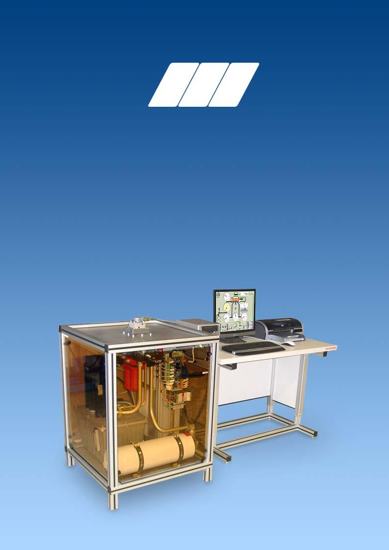
 Servovalve Test Equipment DIETZ automation GmbH 3 Introduction Figure 1: Manual mode of the Test Equipment. is an automatic test equipment for checking, maintenance, and adjustment of servoand proportional
Electro-Proportional Terms and Definitions
 Electro-Proportional Terms and Definitions Valve Deadband The span of operation where there is no flow or pressure output for some specified range of command Hydraulic Valve Gain The characteristic relating
Directional servo-valve of 4-way design
 Courtesy of CM/Flodyne/Hydradyne Motion Control Hydraulic Pneumatic Electrical Mechanical (0) 426-54 www.cmafh.com Directional servo-valve of 4-way design Type 4WSE3E 32 Size 32 Component series 5X Maximum
Directional servo-valve in 4-way design
 Directional servo-valve in 4-way design RE 2983/.11 Replaces: 7.3 1/ Type 4WS.2E... Size Component series X Maximum operating pressure 31 bar Maximum flow 1 l/min HD892 Type 4WSE2ED -X/...K31EV HD893 Type
D661-G...A Series Servovalve With Bushing and Integrated 24 Volt Electronics ISO 4401 Size 05
 D661-G...A Series Servovalve With Bushing and Integrated 24 Volt Electronics ISO 4401 Size 05 OVERVIEW Section Page MOOG SERVO-PROPORTIONAL CONTROL VALVES Overview 2 3 Technical Data 4 5 Performance Specs.
D660 Series Servo-Proportional Control Valves with Integrated Electronics ISO 4401 Size 05 to 10
 D660 Series Servo-Proportional Control Valves with Integrated Electronics ISO 4401 Size 05 to 10 OVERVIEW Section Page MOOG SERVO-PROPORTIONAL CONTROL VALVES Overview 2 3 Technical Data 4 5 Electronics
4-way directional servo-valve
 4-way directional servo-valve RE 29564/09.10 Replaces: 01.07 1/12 Type 4WS.2E Size 6 Component series 2X Maximum operating pressure 315 bar Maximum flow 48 l/min HD5994 Table of contents Contents age Features
Hydraulic Proportional and Closed Loop System Design
 Hydraulic Proportional and Closed Loop System Design Neal Hanson Product Manager Industrial Valves and Electrohydraulics 1 Electrohydraulics Contents 1. Electrohydraulic Principles 2. Proportional Valve
SM4-10/12/15 Servovalves Flows to 57 l/min (15 USgpm) Pressures to 210 bar (3000 psi)
 Pressures to 210 bar (3000 psi)") Vickers Servo Valves SM4-10/12/15 Servovalves Flows to 57 l/min (15 USgpm) Pressures to 210 bar (3000 psi) Released 12/93 651 Introduction Vickers SM4-10/12/15 servovalves can provide system closed loop
Vickers Servo Valves SM4-10/12/15 Servovalves Flows to 57 l/min (15 USgpm) Pressures to 210 bar (3000 psi) Released 12/93 651 Introduction Vickers SM4-10/12/15 servovalves can provide system closed loop
SM4-30 Servovalves Flows to 113 l/min (30 USgpm) Pressures to 140 bar (2000 psi)
 Pressures to 140 bar (2000 psi)") Vickers Servo Valves SM4-30 Servovalves Flows to 113 l/min (30 USgpm) Pressures to 140 bar (2000 psi) Released 1/94 653 Introduction Vickers SM4-30 servovalves can provide system closed loop control with
Vickers Servo Valves SM4-30 Servovalves Flows to 113 l/min (30 USgpm) Pressures to 140 bar (2000 psi) Released 1/94 653 Introduction Vickers SM4-30 servovalves can provide system closed loop control with
D680 Series Mini Direct Drive Valve Piloted Servo-Proportional Control Valves with Integrated Electronics ISO 4401 Size 05 to 08
 D68 Series Mini Direct Drive Valve Piloted Servo-Proportional Control Valves with Integrated Electronics ISO 441 Size 5 to 8 OVERVIEW Section Page MOOG SERVO-PROPORTIONAL CONTROL VALVES Overview 2 3 Technical
Vickers. Servo Valves. SM4-40 Servovalves. Flows to 151 l/min (40 USgpm) Pressures to 350 bar (5000 psi) Released 1/94
 Pressures to 350 bar (5000 psi) Released 1/94") Vickers Servo Valves SM4-40 Servovalves Flows to 151 l/min (40 USgpm) Pressures to 350 bar (5000 psi) Released 1/94 654 Introduction Vickers SM4-40 servovalves can provide system closed loop control with
Vickers Servo Valves SM4-40 Servovalves Flows to 151 l/min (40 USgpm) Pressures to 350 bar (5000 psi) Released 1/94 654 Introduction Vickers SM4-40 servovalves can provide system closed loop control with
SHOCK ABSORBER/DAMPER TESTING MACHINE
 SHOCK ABSORBER/DAMPER TESTING MACHINE Dampening force of a shock absorber is directly proportional to velocity and this parameter needs to be precisely controlled. A small variation of 1mm in a stroke
Troubleshooting Bosch Proportional Valves
 Troubleshooting Bosch Proportional Valves An Informative Webinar Developed by GPM Hydraulic Consulting, Inc. Instructed By Copyright, 2009 GPM Hydraulic Consulting, Inc. TABLE OF CONTENTS Bosch Valves
4/3-way high response directional control valve pilot operated with electrical feedback and integrated electronics (OBE)
") 4/3-way high response directional control valve pilot operated with electrical feedback and integrated electronics (OE) ype 4WRDE Nominal size to 35 Component series 5X Maximum operating pressure 3 bar
4/3-way high response directional control valve pilot operated with electrical feedback and integrated electronics (OE) ype 4WRDE Nominal size to 35 Component series 5X Maximum operating pressure 3 bar
Servo directional valve of 4-way design Type 4WS.2E
 RE 9 83/7.3 Replaces:. Servo directional valve of 4-way design Type 4WS.E Nominal size Series X Maximum operating pressures 31 bar Maximum flow 1 L/min H//D 89/97 Overview of contents Contents age Features
Proportional directional valves, pilot operated, with electrical position feedback and integrated electronics (OBE)
") Proportional directional valves, pilot operated, with electrical position feedback and integrated electronics (OE) RE 29075/08.13 Replaces: 08.04 1/22 Type 4WRKE Size 10 to 35 Component series 3X Maximum
Proportional directional valves, pilot operated, with electrical position feedback and integrated electronics (OE) RE 29075/08.13 Replaces: 08.04 1/22 Type 4WRKE Size 10 to 35 Component series 3X Maximum
What does pressure refer to in relation to hydrostatics and what is it dependent on?
 Question 1 [3 Marks] What does pressure refer to in relation to hydrostatics and what is it dependent on? Question 2 [14 Marks] Make a circuit diagram of a regular hydraulic plant that is used to control
G761 Series Servovalves ISO Size 04
 G761 Series Servovalves ISO 137 Size 4 TWO STAGE SERVOVALVES G761 SERIES SERVOVALVES The G761 Series flow control servovalves are throttle valves for 3- and preferably 4-way applications.they are a high
MCV102A. Pressure Control Servovalve DESCRIPTION FEATURES ORDERING INFORMATION. BLN Issued: October 1998
 MCV102A Pressure Control Servovalve Issued: October 1998 DESCRIPTION The MCV102A Pressure Control Servovalve (PCS) is a twostage, fourway, closed loop electrohydraulic servovalve that provides an output
Rexroth Hydraulics. Servo directional valve of 4-way design Type 4WS.2EM RE /03.99
 RE 29 564/03.99 Replaces: 29 563 Servo directional valve of 4-way design ype 4WS.2EM Nominal size 6 Series 2X Maximum operating pressures 210 / 315 bar Maximum flow 40 L/min H//D 5994/98 ype 4WS2EM 6-2X/.E...K17EV
Directional control valves, direct operated, with electrical position feedback and integrated electronics (OBE)
") Directional control valves, direct operated, with electrical position feedback and integrated electronics (OBE) Type 4WRPE RE 29122 Edition: 2014-11 Size 10 Component series 3X Maximum operating pressure
Directional control valves, direct operated, with electrical position feedback and integrated electronics (OBE) Type 4WRPE RE 29122 Edition: 2014-11 Size 10 Component series 3X Maximum operating pressure
Proportional pressure relief valve, directly operated, without/with integrated electronics (OBE)
") Proportional pressure relief valve, directly operated, without/with integrated electronics (OBE) ype DBE and DBEE RE 96 Edition: 03-06 Replaces: 04.3 Size 6 Component series 6X Maximum operating pressure
Proportional pressure relief valve, directly operated, without/with integrated electronics (OBE) ype DBE and DBEE RE 96 Edition: 03-06 Replaces: 04.3 Size 6 Component series 6X Maximum operating pressure
4-way directional servo valve Type 4WS.2E
 RE 29 91/06.02 Replaces: 03.93 4-way directional servo valve Type 4WS.2E Nominal size 16 Series 2X Maximum operating pressure 2/31 bar Maximum flow 3 L/min Overview of contents Contents Page Features 1
631 Series Servovalves ISO 4401 Size 05
 631 Series Servovalves ISO 4401 Size 05 TWO STAGE SERVOVALVES 631 SERIES SERVOVALVES The 631 Series flow control servovalves are throttle valves for 3- and preferably 4-way applications.they are a medium
D633/D634 SERVOVALVES FOR ELECTROHYDRAULIC POSITION, VELOCITY, PRESSURE OR FORCE CONTROL SYSTEMS WITH HIGH DYNAMIC RESPONSE REQUIREMENTS
 SERVOVALVES DIRECT DRIVE SERVOVALVES D633/D634 SERVOVALVES FOR ELECTROHYDRAULIC POSITION, VELOCITY, PRESSURE OR FORCE CONTROL SYSTEMS WITH HIGH DYNAMIC RESPONSE REQUIREMENTS Rev. 2, 04/2009 ISO 4401 SIZES
3/3 servo directional control valve with mechanical position feedback
 Courtesy of CMA/Flodyne/Hydradyne Motion Control Hydraulic neumatic Electrical Mechanical () 426-4 www.cmafh.com 3/3 servo directional control valve with mechanical position feedback Type 4WS2EM...XN...-114
Module 6 Assignment Part A
 Module 6 Assignment Part A TOTAL MARKS Part A = 192 TOTAL QUESTIONS Part A = 36 Question 1 [3 Marks] What does pressure refer to in relation to hydrostatics and what is it dependent on? Question 2 [14
Servo solenoid valves with positive overlap Position feedback (Lvdt DC/DC ±10 V)
") Servo solenoid valves with positive overlap Position feedback (Lvdt DC/DC ±10 V) RE 29087/01.05 1/22 Replaces: 05.04 Type 4WRL 10 35, symbols E. / W. Nominal size 10, 16, 25, 35 Unit series 3X Maximum
Servo solenoid valves with positive overlap Position feedback (Lvdt DC/DC ±10 V) RE 29087/01.05 1/22 Replaces: 05.04 Type 4WRL 10 35, symbols E. / W. Nominal size 10, 16, 25, 35 Unit series 3X Maximum
Pilot-Operated Proportional DC Valve Series D*1FH
 Characteristics The pilot-operated proportional DC valves series of the D*1FH series are high-performance valves with electronic spool position feedback. These valves are available in sizes NG10 to NG2
4/3 directional control valve, pilot operated, with electric position feedback and integrated electronics (OBE)
") 4/ directional control valve, pilot operated, with electric position feedback and integrated electronics (OBE) RE 977/.1 Replaces: 1.9 1/16 Type 4WRVE 1...7, symbols V, V1 Sizes 1, 16, 5, 7 Component series
4/ directional control valve, pilot operated, with electric position feedback and integrated electronics (OBE) RE 977/.1 Replaces: 1.9 1/16 Type 4WRVE 1...7, symbols V, V1 Sizes 1, 16, 5, 7 Component series
KVF. Flow Control Servovalve (FCS) DESCRIPTION FEATURES ORDERING INFORMATION KVF X X X X X. BLN Issued: February 2004
 DESCRIPTION FEATURES ORDERING INFORMATION KVF X X X X X. BLN Issued: February 2004") DESCRIPTION KVF Flow Control Servovalve (FCS) Issued: February 004 The KVF Flow Control Servovalve is a precision servovalve that provides an output flow rate proportional to a low power electrical input
DESCRIPTION KVF Flow Control Servovalve (FCS) Issued: February 004 The KVF Flow Control Servovalve is a precision servovalve that provides an output flow rate proportional to a low power electrical input
STAR. series. 2-Stage Servovalve Rated flows up to 7 l/m. Features
 STAR series 2 2-Stage Servovalve Rated flows up to 7 l/m Features Miniature design Maximum operating pressure 315 bar ISO 1372-1-1--92 mounting pattern Internal pilot supply (4 port) Suitable for 3-way
Servo and Proportional Valves
 Servo and Proportional Valves Servo and proportional valves are used to precisely control the position or speed of an actuator. The valves are different internally but perform the same function. A servo
Hydraulic energy control, conductive part
 Chapter 2 2 Hydraulic energy control, conductive part Chapter 2 Hydraulic energy control, conductive part To get the hydraulic energy generated by the hydraulic pump to the actuator, cylinder or hydraulic
G761 Series Servovalves ISO Size 04
 G761 Series Servovalves ISO 137 Size 4 TWO STAGE SERVOVALVES G761 SERIES SERVOVALVES The G761 Series flow control servovalves are throttle valves for 3-, and preferably 4-way applications.they are a high
STAR. series. 2-Stage Servovalve Flight Simulation Motion Control. Features
 STAR series 99 2-Stage Servovalve Flight Simulation Motion Control Features Maximum operating pressure 14 bar ISO 1372-6-5--92 mounting pattern Internal pilot supply (4 port) Low hysteresis & zero point
Proportional pressure reducing valve, pilot operated
 Proportional pressure reducing valve, pilot operated RE 29175/7.5 Replaces: 11.2 1/1 Types DRE and ZDRE Size 6 Component series 1X Maximum operating pressure 21 bar Maximum flow l/min H446 Table of contents
STAR. series. Servo proportional valve Rated flows up to 80 l/m. Features
 STAR series 65 Servo proportional valve Rated flows up to 8 l/m Features Maximum operating pressure 15 bar ISO 172-4-4--92 mounting pattern Internal pilot supply (4 port) Suitable for -way or 4-way applications
series 2-Stage Servovalve Rated flows up to 80 l/m Features
 series 65 2-Stage Servovalve Rated flows up to 8 l/m Features Maximum operating pressure 15 bar ISO 172-4-4--92 mounting pattern Internal pilot supply (4 port) Suitable for -way or 4-way applications High
Pilot Operated Proportional DC Valve Series D*1FW / D*1FT
 Characteristics The D*1FW / D*1FT pilot-operated proportional DC valves are available in NG10 (CETOP5), NG16 (CETOP7) and NG25 (CETOP8). These valves (D*1FW) are controlled electrically with the external
Jet Pipe Servovalves
 Servovalves OVERVIEW Section Page MOOG JET PIPE SERVOVALVES Overview 2 3 Technical Data 4 6 Electrical Characteristics 7 Performance Specs. 8-15 Installation Procedures 16-17 Ordering Information 18-19
Servo solenoid valves with electrical position feedback (Lvdt DC/DC) (ruggedized design)
 (ruggedized design)") Servo solenoid valves with electrical position feedback (Lvdt DC/DC) (ruggedized design) RE 29026/01.05 1/14 Replaces: 11.02 Type 4WRPH Size 6, 10 Unit series 2X Maximum working pressure P, A, B 315 bar,
Servo solenoid valves with electrical position feedback (Lvdt DC/DC) (ruggedized design) RE 29026/01.05 1/14 Replaces: 11.02 Type 4WRPH Size 6, 10 Unit series 2X Maximum working pressure P, A, B 315 bar,
Proportional directional valve, pilot-operated, with integrated electronics (OBE)
") Proportional directional valve, pilot-operated, with integrated electronics (OBE) Type WFCE RE 943 Edition: 7- Replaces: 6- Size 6 5 Component series X Maximum operating pressure 4 bar Maximum flow 5 l/min
Proportional directional valve, pilot-operated, with integrated electronics (OBE) Type WFCE RE 943 Edition: 7- Replaces: 6- Size 6 5 Component series X Maximum operating pressure 4 bar Maximum flow 5 l/min
771, 772, 773 Series Servovalves
 771, 772, 773 Series Servovalves TWO STAGE SERVOVALVES 771/2/3 SERIES SERVOVALVES The 771/2/3 Series flow control servovalves are throttle valves for 3- and preferably 4-way applications.they are a high
Proportional directional control valve, pilot operated with on-board electronics (OBE) and inductive position transducer
 and inductive position transducer") Proportional directional control valve, pilot operated with on-board electronics (OBE) and inductive position transducer RE 29076/12.05 1/24 Type 4WRBKE Nominal size (NG) 10, 16, 27, 35 Unit series 1X
Proportional directional control valve, pilot operated with on-board electronics (OBE) and inductive position transducer RE 29076/12.05 1/24 Type 4WRBKE Nominal size (NG) 10, 16, 27, 35 Unit series 1X
Proportional flow control valve, 2-way version
 Proportional flow control valve, 2-way version Type 2FRE 6 Size 6 Component series 2X Maximum operating pressure 20 bar Maximum flow 25 l/min Table of contents Contents Page Features Ordering code 2 Standard
Planning and Commissioning Guideline for NORD IE4 Motors with NORD Frequency Inverters
 Planning and Commissioning Guideline for NORD IE4 Motors with NORD Frequency Inverters General Information From their basic function, motors with efficiency class IE4 are synchronous motors and are suitable
Understanding the benefits of using a digital valve controller. Mark Buzzell Business Manager, Metso Flow Control
 Understanding the benefits of using a digital valve controller Mark Buzzell Business Manager, Metso Flow Control Evolution of Valve Positioners Digital (Next Generation) Digital (First Generation) Analog
test with confidence HV Series TM Test Systems Hydraulic Vibration
 test with confidence HV Series TM Test Systems Hydraulic Vibration Experience. Technology. Value. The Difference. HV Series TM. The Difference. Our philosophy is simple. Provide a system designed for optimum
4/4 directional control valves, direct operated, with electrical position feedback and integrated electronics (OBE)
") 4/4 directional control valves, direct operated, with electrical position feedback and integrated electronics (OBE) Type 4WRPEH RE 29121 Edition: 2014-01 Size 6 Component series 3X Maximum operating pressure
4/4 directional control valves, direct operated, with electrical position feedback and integrated electronics (OBE) Type 4WRPEH RE 29121 Edition: 2014-01 Size 6 Component series 3X Maximum operating pressure
INVITATION FOR QUOTATION. TEQIP-II/2015/GJ1G02/Shopping/M-EE-09
 INVITATION FOR QUOTATION TEQIP-II/2015/GJ1G02/Shopping/M-EE-09 02-Dec-2015 Sub: Invitation for Quotations for supply of Goods Dear Sir, 1. You are invited to submit your most competitive quotation for
Proportional pressure reducing valve, pilot operated. Type DRE(M) and DRE(M)E. Features. Contents. RE Edition: Replaces: 11.
 and DRE(M)E. Features. Contents. RE Edition: Replaces: 11.") Proportional pressure reducing valve, pilot operated Type DRE(M) and DRE(M)E RE 29278 Edition: 212-12 Replaces: 11.11 Size 32 Component series 6X Maximum operating pressure 315 bar Maximum flow: 3 l/min
Proportional pressure reducing valve, pilot operated Type DRE(M) and DRE(M)E RE 29278 Edition: 212-12 Replaces: 11.11 Size 32 Component series 6X Maximum operating pressure 315 bar Maximum flow: 3 l/min
three different ways, so it is important to be aware of how flow is to be specified
 Flow-control valves Flow-control valves include simple s to sophisticated closed-loop electrohydraulic valves that automatically adjust to variations in pressure and temperature. The purpose of flow control
Developing PMs for Hydraulic System
 Developing PMs for Hydraulic System Focus on failure prevention rather than troubleshooting. Here are some best practices you can use to upgrade your preventive maintenance procedures for hydraulic systems.
Proportional pressure relief valve, pilot operated
 Proportional pressure relief valve, pilot operated RE 29142/05.05 Replaces: 11.02 1/8 Types DE(M) and DE(M)E Size 32 1) Component series 3X Maximum operating pressure 3 bar Maximum flow 600 L/min H1764
Servo solenoid valves with on-board electronics (OBE)
") Servo solenoid valves with on-board electronics (OBE) RE 29045/10.05 Replaces: 01.05 1/12 Type 5WRPE 10 Size 10 Unit series 2X Maximum working pressure P 1, P 2, A, B 210 bar, T 50 bar Nominal flow rate
Servo solenoid valves with on-board electronics (OBE) RE 29045/10.05 Replaces: 01.05 1/12 Type 5WRPE 10 Size 10 Unit series 2X Maximum working pressure P 1, P 2, A, B 210 bar, T 50 bar Nominal flow rate
Servo solenoid valves with electrical position feedback (Lvdt DC/DC ±10 V)
") Servo solenoid valves with electrical position feedback (Lvdt DC/DC ±10 V) Type 5WRP 10 Size 10 Unit series 2X Maximum working pressure P 1, P 2, A, B 210 bar, T 50 bar Nominal flow rate 70 l/min ( p 11
Servo solenoid valves with electrical position feedback (Lvdt DC/DC ±10 V) Type 5WRP 10 Size 10 Unit series 2X Maximum working pressure P 1, P 2, A, B 210 bar, T 50 bar Nominal flow rate 70 l/min ( p 11
Proportional pressure reducing valve, pilot operated
 Proportional pressure reducing valve, pilot operated Type DRE and DREE Sizes 10 and 25 1) Component series 6X Maximum operating pressure Maximum flow Table of contents Content 315 bar 300 l/min Page Features
2-way proportional throttle valve for block installation
 -way proportional throttle valve for block installation RE 90/07.05 Replaces: 03.00 / Types FE; FEE Size 6 Component series X Maximum operating pressure 35 bar Maximum flow 90 L/min bei p = 0 bar H4538
PRM7-04. Functional Description HA /2012. Proportional Directional Control Valves. Replaces HA /2009
 Proportional Directional Control Valves PRM7-6/ Size D () bar (6 PSI) L/min (. GPM ) Replaces /9 Digital control Compact design Operated by proportional solenoids High sensitivity and slight hysteresis
HYDROTRAINER-200 Hydraulics - Electro-hydraulics
 HYDROTRAINER-200 Hydraulics - Electro-hydraulics Hydraulics and electro-hydraulics within your reach Why HYDROTRAINER-200? All components included are industrial which guarantees real learning and future
Servo solenoid valves with electrical position feedback (Lvdt AC/AC)
") Servo solenoid valves with electrical position feedback (Lvdt AC/AC) Type 4WRPH6 Size 6 Unit series 1X Maximum working pressure 250 bar Nominal flow rate 4...40 l/min ( p 70 bar) List of contents Contents
Servo solenoid valves with electrical position feedback (Lvdt AC/AC) Type 4WRPH6 Size 6 Unit series 1X Maximum working pressure 250 bar Nominal flow rate 4...40 l/min ( p 70 bar) List of contents Contents
Solenoid Pilot Operated Proportional Directional Control Valve
 Solenoid Pilot Operated Proportional Directional Control Valve Features hese solenoid pilot operated proportional directional control valves use a nozzle flapper valve as pilot valve and perform spool
Directional control valves, pilot-operated, with electrical position feedback and integrated electronics (OBE) Type 4WRDE. Contents.
 Type 4WRDE. Contents.") Directional control valves, pilot-operated, with electrical position feedback and integrated electronics (OE) ype 4WRDE RE 997 Edition: 6-5 Replaces: 99 (NG and NG6) Sizes and 6 Component series 6X Maximum
Directional control valves, pilot-operated, with electrical position feedback and integrated electronics (OE) ype 4WRDE RE 997 Edition: 6-5 Replaces: 99 (NG and NG6) Sizes and 6 Component series 6X Maximum
series 2-Stage Servovalve Rated flows up to 20 l/m Features
 series 46 2-Stage Servovalve Rated flows up to 2 l/m Features Standard & high response versions Maximum operating pressure 15 bar ISO 441---4 mounting pattern Internal pilot supply (4 port) Suitable for
3-way servo solenoid valves, cartridge type, pilot operated, with inductive position transducer
 3-way servo solenoid valves, cartridge type, pilot operated, with inductive position transducer Type 3WRCB 25...50 Nominal size (NG) 25, 32, 50 Unit series 1X Maximum working pressure P, A, T, X, Z 315
Proportional cartridge throttle valve, with inductive position transducer, pilot operated
 Proportional cartridge throttle valve, with inductive position transducer, pilot operated RE 29215/09.05 1/18 Type FESX Nominal size 16, 25, 32, 40, 50 Unit series 1X Maximum working pressure A, B, X 315
PRM7-06. Functional Description HA /2006. Proportional Directional Control Valves. Replaces HA /2002
 Proportional Directional Control Valves PRM7-6 HA 59 /6 Size D (6)...6 PSI ( bar)...6 GPM ( L/min) Replaces HA 57 / Digital control Compact design Operated by proportional solenoids High sensitivity and
PRM7-06. Functional Description HA /2014. Proportional Directional Control Valves. Replaces HA /2013
 Proportional Directional Control Valves PRM7-6 / Size 6 (D ) bar (76 PSI) L/min (.6 GPM) Replaces HA 7 / Digital control Compact design Operated by proportional solenoids High sensitivity and slight hysteresis
Proportional pressure reducing valve, pilot operated
 Proportional pressure reducing valve, pilot operated RE 29178/4.5 Replaces: 11.2 1/1 Types DRE(M) and DRE(M)E Size 32 1) Component series 4X Maximum operating pressure 315 bar Maximum flow 3 L/min H2448
Servo solenoid valves with positive overlap and on-board electronics
 Servo solenoid valves with positive overlap and on-board electronics RE 29089/01.05 1/22 Replaces: 05.04 Type 4WRLE 10...35, symbols E./W. Nominal size 10, 16, 25, 35 Unit series 3X Maximum working pressure
STAR. series. 2-Stage Servovalve Rated flows up to 20 l/m. Features
 STAR series 454 2-Stage Servovalve Rated flows up to 2 l/m Features Standard & high response versions Maximum operating pressure 15 bar ISO 172-2-2-2 mounting pattern Internal pilot supply (4 port) Suitable
Proportional flow control valve 2-way version, Type 2FRE 10, Huade América 1
 Proportional flow control valve 2-way version, Type 2FRE 10, 16... Huade América 1 EIJING HUADE HYDRAULIC INDUSTRIAL GROUP CO.,LTD. Proportional flow control valve 2-way version Type 2FRE 10 16... Size
72 Series Servovalves
 72 Series Servovalves TWO STAGE SERVOVALVES 72 SERIES SERVOVALVES The 72 Series flow control servovalves are throttle valves for 3 and preferably 4-way applications.they are a high performance, two-stage
Functional Symbols and Application Notes
 Functional Symbols and pplication Notes Model Types KHDG5V Shown Simplified symbol Model Types KHDG5V Shown K()FDG5V symbols identical, but omit pilot-stage LVDTs Simplified symbol T T Detailed symbol
Directional control valves, pilot-operated, with electrical position feedback and integrated electronics (OBE) Type 4WRTE. Features.
 Type 4WRTE. Features.") Directional control valves, pilot-operated, with electrical position feedback and integrated electronics (OBE) ype 4WRE RE 29083 Edition: 2017-03 Replaces: 08.13 Size 10 35 Component series 4X Maximum
Directional control valves, pilot-operated, with electrical position feedback and integrated electronics (OBE) ype 4WRE RE 29083 Edition: 2017-03 Replaces: 08.13 Size 10 35 Component series 4X Maximum
MCV106A. Hydraulic Displacment Control-PV DESCRIPTION FEATURES ORDERING INFORMATION. BLN Issued: March 1991
 DESCRIPTION MCV106A Hydraulic Displacment Control-PV Issued: March 1991 The MCV106A Hydraulic Displacement Control (HDC) is a costeffective hydraulic pump stroke control which uses mechanical feedback
Seismic Engineering Research Infrastructures for European Synergies. JRA1: Small Lab Experience. Iasi 13th July 2009
 Seismic Engineering Research Infrastructures for European Synergies Structural Dynamics Research Group Department of Engineering Science University of Oxford JRA1: Small Lab Experience Iasi 13th July 2009
Specification subject to change without notice! All rights reserved page 1 of 5
 Electro Hydraulic Servo Valve Single Stage Hydraulic Symbol Introduction: The HVM 068 is a single stage servo valve in spool and sleeve construction. It is designed special for low pressure applications
4/3 proportional directional control valve, without position control, with on-board electronics (OBE)
") 4/3 proportional directional control valve, without position control, with on-board electronics (OBE) Type 4WRBAE..E.. /..W.. Nominal size (NG) 6, 10 Unit series 2X Maximum working pressure P, A, B 315
4/3 proportional directional control valve, without position control, with on-board electronics (OBE) Type 4WRBAE..E.. /..W.. Nominal size (NG) 6, 10 Unit series 2X Maximum working pressure P, A, B 315
2- and 3-way high-response cartridge valve
 2- and -way high-response cartridge valve RE 2917/.1 Replaces: 1.5 1/24 ype.wrce.../ Size 2, 4, and 5 Component series 2 Maximum operating pressure 42 bar Maximum flow 45 l/min ype WRCE...-2/ ype 2WRCE...-2/
Proportional flow control valve 2-way versiontype 2FRE 6...RC
 Proportional flow control valve 2-way versiontype 2FRE 6...RC Huade América 1 BEIJING HUADE HYDRAULIC INDUSTRIAL GROUP CO.,LTD. Proportional flow control valve 2-way version Type 2FRE 6...RC Size 6 up
Servo solenoid valves with on-board electronics (OBE)
") Servo solenoid valves with on-board electronics (OBE) RE 29077/01.05 1/16 Replaces: 01.03 Type 4WRVE10...25 Size 10, 16, 25 Unit series 2X Maximum working pressure P, A, B 350 bar, T, X, Y 250 bar Nominal
Servo solenoid valves with on-board electronics (OBE) RE 29077/01.05 1/16 Replaces: 01.03 Type 4WRVE10...25 Size 10, 16, 25 Unit series 2X Maximum working pressure P, A, B 350 bar, T, X, Y 250 bar Nominal
Servo solenoid valves with on-board electronics (OBE)
") Servo solenoid valves with on-board electronics (OBE) RE 29088/01.05 1/18 Replaces: 05.04 Type 4WRLE10...35, symbols V/V1 Size 10, 16, 25, 35 Unit series 3X Maximum working pressure P, A, B 350 bar, T,
Servo solenoid valves with on-board electronics (OBE) RE 29088/01.05 1/18 Replaces: 05.04 Type 4WRLE10...35, symbols V/V1 Size 10, 16, 25, 35 Unit series 3X Maximum working pressure P, A, B 350 bar, T,
OVERVIEW SERVO VALVE RANGE
 OVERVIEW SERVO VALVE RANGE FLEXIBLE DESIGN, HIGH PRODUCTIVITY WHAT MOVES YOUR WORLD VALVE TYPES EXPLAINED MECHANICAL FEEDBACK (MFB) ELECTRICAL FEEDBACK (EFB) DIRECT DRIVE VALVE (DDV) DIGITAL (DCV) AND
Proportional pressure relief valve Type DBETRE
 RE 9 68/.99 Proportional pressure relief valve Type DBETRE Nominal size 6 Series X Max. operating pressure 5 bar Max. flow up to L/min H/A/D 67/99 Type DBETRE-X/ G4KA with integrated control electronics
Pilot operated proportional directional valves
 /6 Pilot operated proportional directional valves 6. Type WRLE Sizes to 7 Up to 5 bar Up to L/min Contents Function and configuration Symbols Specifications Technical data -5 Electrical connection Technical
CENTROIDTM. AC Brushless Drive. Product Spec Sheet
 4 Axis, up to 2 KW motors Brake Output for each axis Overtemp and Overcurrent Protection All-software Configuration Self-cooled Fiber Optic Control CENTROIDTM AC Brushless Drive Product Spec Sheet AC Brushless
Proportional and Servo Valve Index
 Proportional and Servo Valve Index Proportional and Servo Valves Leading the Way for Intelligent Hydraulics Hydraulic valves which are electrically operated by proportional solenoids are classifi ed as
ALD3 Diaphragm Valve Technical Report
 ALD Diaphragm Valve Technical Report Scope This technical report provides data on Swagelok ALD normally closed diaphragm valves. The report covers: helium seat leak testing valve flow consistency analysis
Proportional pressure relief valve, pilot operated
 Electric Drives and Controls Hydraulics Linear Motion and ssembly Technologies Pneumatics Service Proportional pressure relief valve, pilot operated R 29160/04.05 Replaces: 06.98 1/10 Model DE(M) and DE(M)E
Proportional Pressure Reducing Valve Series D1FV
 Characteristics roportional ressure Reducing Valve Series D1FV he proportional pressure reducing valves series D1FV are available with and without onboard electronics (OE). D1FV OE he digital onboard electronics
Servo solenoid valves with on-board electronics (OBE)
") Servo solenoid valves with on-board electronics (OBE) RE 29037/10.05 Replaces: 01.05 1/12 Type 4WRPEH 10 Size 10 Unit series 2X Maximum working pressure P, A, B 315 bar, T 250 bar Nominal flow rate 50...100
Servo solenoid valves with on-board electronics (OBE) RE 29037/10.05 Replaces: 01.05 1/12 Type 4WRPEH 10 Size 10 Unit series 2X Maximum working pressure P, A, B 315 bar, T 250 bar Nominal flow rate 50...100
: Automation Laboratory 1
 Table A.1 shows elements found in FluidSIM library with a brief description for each of them. Compressed air supply The compressed air supply provides the needed compressed air. It contains a pressure
CHAPTER 6 MECHANICAL SHOCK TESTS ON DIP-PCB ASSEMBLY
 135 CHAPTER 6 MECHANICAL SHOCK TESTS ON DIP-PCB ASSEMBLY 6.1 INTRODUCTION Shock is often defined as a rapid transfer of energy to a mechanical system, which results in a significant increase in the stress,
series 2-Stage Servovalve Rated flows up to 55 l/m Features
 series 456 2-Stage Servovalve Rated flows up to 55 l/m Features Standard & high response versions Maximum operating pressure 15 bar Special mounting pattern Internal pilot supply (4 port) Suitable for
3. DESCRIPTION OF SHAKING TABLE SYSTEM COMPONENTS
 17 3. DESCRIPTION OF SHAKING TABLE SYSTEM COMPONENTS 3.1. INTRODUCTION The earthquake simulator is a system that consists of several components which must be designed to effectively work together. Each
2 Poster Motorcycle Ride Simulator
 2 Poster Motorcycle Ride Simulator The World of Ride Simulators The 2 Poster Motorcycle Road Simulator System is designed to reproduce responses experienced under normal driving conditions, to test motorcycle
HS CYCLIC CUM STATIC TRIAXIAL TEST SYSTEM
 HS28.610 CYCLIC CUM STATIC TRIAXIAL TEST SYSTEM Meets the essential requirements of ASTM-5311/3999 Introduction The system is a highly advanced combination of hydraulic and pneumatic technology where σ1