JRVCS2 TROUBLESHOOTING
|
|
|
- Charla Mathews
- 6 years ago
- Views:
Transcription

 Body Control Module (BCM) Table of contents.")

1 JRVCS2 TROUBLESHOOTING This guide is made to ease troubleshooting the in-command system. It will cover the wiring code and where those wires are connected to the Body Control Module (BCM) and Display Commander (DC), system functions, and what to look for to discern where a problem could be. Display Commander (DC) Body Control Module (BCM) Table of contents...page 1 Keystone wiring code...page 2 Body Control Module wiring diagram...page 3, 4 BCM Pin Values...Page 5-7 Functionality Testing and Pairing...Page 8-12 Troubleshooting...Page 13, 14 Page 1


2 Keystone 12 VDC Wire Standard Page 2

 are at the Top Left side.")
3 Wiring Guide for the BCM BCM Pins 1-31 are on the Left side, ascending from Top to Bottom BCM Pins are on the Bottom and ascend from Left to Right BCM Pins on the Right side, ascending from Bottom to Top. BCM Pins, RX, TX, and +12V DC (DC RX/TX wires) are at the Top Left side. Page 3

4 Wiring Guide for the BCM to DC DC, RX, TX and +12V are on the back of the DC. Note: The RX pin on the DC connects to the TX pin on the BCM. The TX pin on the DC connects to the RX pin on the BCM. If the TX and RX wires are crossed, the DC and BCM will not communicate and no functions will work., RX, TX, Page 4
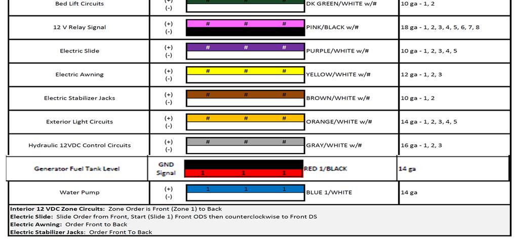
5 BCM Pin Values TANK LEVEL Pin NAME BCM FUNCTION NOTE A DMM 1 FRESH 1 TANK IN 0-185KOHM 2 FRESH 2 TANK IN 0-185KOHM 3 BLACK 1 TANK IN 0-185KOHM 4 BLACK 2 TANK IN 0-185KOHM 5 GREY 1 TANK IN 0-185KOHM 6 GREY 2 TANK IN 0-185KOHM 7 GREY 3 TANK IN 0-185KOHM 0-.74V = EMPTY ( ) V = 1/3 ( ) V = 2/3 ( ) 3.6V = FULL ( ) MEASURE FROM PIN 10 TO EACH INPUT 8 TANK COMMON 7VDC OUTPUT 7VDC 9 LIGHT GROUP1 12V 15A IN INPUT VDC VDC VDC VDC VDC VDC VDC 10 LIGHT GROUP1 JUST A TERMINAL NO PCB TRACE NEEDED 11 LIGHT GROUP1 12V 15A OUT OUTPUT FROM ZONE1 LIGHT IN 12V 12 LIGHT GROUP2 12V 15A IN INPUT 13 LIGHT GROUP2 JUST A TERMINAL NO PCB TRACE NEEDED 14 LIGHT GROUP2 12V 15A OUT OUTPUT FROM ZONE2 LIGHT IN 12V 15 LIGHT GROUP3 12V 15A IN INPUT 16 LIGHT GROUP3 JUST A TERMINAL NO PCB TRACE NEEDED LIGHTING I/O 17 LIGHT GROUP3 12V 15A OUT OUTPUT FROM ZONE3 LIGHT IN 12V 18 LIGHT GROUP4 12V 15A IN INPUT 19 LIGHT GROUP4 JUST A TERMINAL NO PCB TRACE NEEDED 15A 20 LIGHT GROUP4 12V 15A OUT OUTPUT FROM ZONE3 LIGHT IN 12V 21 EXTERIOR LIGHT 12V 15A IN INPUT 22 EXTERIOR LIGHT JUST A TERMINAL NO PCB TRACE NEEDED 23 EXTERIOR LIGHT 12V 15A OUT 24 SECURITY LIGHT 12V 15A IN INPUT OUTPUT FROM EXTERIOR LIGHT 12V IN 25 SECURITY LIGHT JUST A TERMINAL NO PCB TRACE NEEDED 26 SECURITY LIGHT 12V 15A OUT OUTPUT FROM INTERIOR LIGHT 12V IN 27 AWNING LIGHT 12V 3A OUT POWER FROM 15A INPUT JUST LIKE SECURITY LIGHT FUNCTION 3A 28 AWNING LIGHT PASS THROUGH CONNECTION Page 5
6 FUEL STATION 29 Fuel Station Tank Level IN Ohm 33 OHM= FULL ( ), 49 OHM= 2/3 ( ) 127 OHM= 1/3 ( ), 240 OHM= Empty ( ) 30 FUEL STATION PASS THROUGH CONNECTION AUX TRIGGER 31 AUX1 +12V OUT PROGRAMAMBLE 12V LATCH OR MOMENTARY 1A Ω GENERATOR HYD LANDING JACKS 32 GENERATOR START OUT OUTPUT UNTIL BUTTON IS RELEASED 33 GENERATOR PRIME/STOP OUT OUTPUT 34 GENERATOR SERVICE 12V IN 12V PULSES INPUT GENERATOR HOUR METER 12V IN GENERATOR FUEL LEVEL IN OHM 12V INPUT TRIGGERS TIMER TO START 33 OHM= FULL ( ), 49 OHM= 2/3 ( ) 127 OHM= 1/3 ( ), 240 OHM= Empty ( ) 37 GENERATOR PASS THROUGH CONNECTION V HYDRAULIC VALVE 1.5A (Landing Gear) HYDRAULIC VALVE 1.5A (Landing Gear) OUTPUT 12V 1.5A PASS THROUGH CONNECTION 40 HYDRAULIC EXTEND OUT 12V 2A OUTPUT 12V FOR RETRACT VALVE 41 2A HYDRAULIC RETRACT OUT 12V OUTPUT 12V FOR EXTEND VALVE 2A HYD SLIDE V HYDRAULIC VALVE 1.5A (Hyd slide sol) OUTPUT 12V 43 HYDRAULIC VALVE 1.5A (Hyd slide sol) PASS THROUGH CONNECTION 1.5A 44 AUX2 +12V OUT PROGRAMAMBLE 12V LATCH OR MOMENTARY 45 AUX3 +12V OUT PROGRAMAMBLE 12V LATCH OR MOMENTARY 46 AUX4 +12V OUT PROGRAMAMBLE 12V LATCH OR MOMENTARY 47 ALARM1 +12V IN PROGRAMAMBLE 12V ALARM ON OR OFF INPUT 1A 48 ALARM2 +12V IN PROGRAMAMBLE 12V ALARM ON OR OFF INPUT 49 ALARM3 +12V IN PROGRAMAMBLE 12V ALARM ON OR OFF INPUT 50 ALARM4 +12V IN PROGRAMAMBLE 12V ALARM ON OR OFF INPUT AUX 12V TRIGGERS TRAVEL LOCK 51 LOCKOUT SIGNAL IN 12V 12V INPUT FROM TOW VEHICLE BRAKE WATER HEATER LOCK OUT SLIDES, JACKS & AWNINGS WHEN PRESENT 52 WATER HEATER PASS THROUGH CONNECTION WATER HEATER GAS +12V 1A OUT WATER HEATER ELECTRIC +12V 1A OUT OUTPUT TO GAS OUTPUT TO ELECTRIC Ω V WATER HEATER FAULT IN RECEIVE 12V FAUILT SIGNAL 1A WATER PUMP 56 WATER PUMP +12V OUT 10A Output 12V to WATER PUMP 10A 57 WATER PUMP 58 WATER PUMP +12V IN 10A INPUT JUST A TERMINAL NO PCB TRACE NEEDED Page 6
7 59 OUT (AWNING#2) OUTPUT 12V POWER & GROUND AWNINGS 60 12V OUT 15 AMP (AWNING#2) OUTPUT 12V GROUND & POWER 61 OUT (AWNING#1) OUTPUT 12V POWER & GROUND 15A 62 12V OUT 15 AMP (AWNING#1) OUTPUT 12V GROUND & POWER 63 OUT (REAR JACKS) OUTPUT 12V IN POWER & GROUND JACKS 64 12V OUT 30 AMP (REAR JACKS) OUTPUT 12V IN GROUND & POWER 65 OUT (FRONT JACKS) OUTPUT 12V IN POWER & GROUND 66 12V OUT 30 AMP (FRONT JACKS) OUTPUT 12V IN GROUND & POWER 67 OUT (SLIDE#5) OUTPUT 12V IN POWER & GROUND 68 12V OUT 30 AMP (SLIDE#5) OUTPUT 12V IN GROUND & POWER 69 OUT (SLIDE#4) OUTPUT 12V IN POWER & GROUND 70 12V OUT 30 AMP (SLIDE#4) OUTPUT 12V IN GROUND & POWER 30A ELEC. SLIDE 1 ~ 5 71 OUT (SLIDE#3) OUTPUT 12V IN POWER & GROUND 72 12V OUT 30 AMP (SLIDE#3) OUTPUT 12V IN GROUND & POWER 73 OUT (SLIDE#2) OUTPUT 12V IN POWER & GROUND 74 12V OUT 30 AMP (SLIDE#2) OUTPUT 12V IN GROUND & POWER 75 OUT (SLIDE#1) OUTPUT 12V IN POWER & GROUND 76 12V OUT 30 AMP (SLIDE#1) OUTPUT 12V IN GROUND & POWER POWER 77 GROUND IN INPUT FROM CHASSIS GROUND 78 12V IN 15 AMP AWNING POWER INPUT 79 12V IN 30 AMP SLIDE & JACK POWER 80 + IN POWER INPUT READ VOLTAGE ON INPUT( + IN POWER) 15A 30A Page 7


8 JRVCS2 Functionality Test and Pairing The BCM should be wired correctly, without loose connections, and connected to 12 VDC at pin 80. A RED LED will indicate that the BCM is receiving 12 VDC. The 2 toggle switches on the BCM correspond to the 2 dials underneath them. (In the event where communication between the DC and BCM is non-functioning, these switches will enable "manual" functions of the selected devices) The Left switch and knob are used for Electric Awnings and Jacks. (Hydraulic Jacks are manually controlled at the Hydraulic Pump. See the Hydraulic Pump Manual Override in the RV owner's manual), and the Right switch and knob are used for Electric Slides 1-5. The DC will be mounted in a "all access" area near the entrance. On the DC, hold down the Power button (the left button) for 5 seconds. After a moment, the Passcode Screen will appear. Enter your Passcode. If this is the first time the DC has been powered on, an End User License Agreement (EULA)screen will appear. Upon accepting the EULA, a Enter New Passcode screen will appear. Enter your new passcode and confirm. Page 8


, it will need")
9 The DC will now bring up the Home Screen If the Floor Plan has been loaded, All the devices should be listed with corresponding actitation buttons Starting with the Lights, cycle ON/OFF, IN/OUT each device. All the functions should be smooth and instantaneous. Ensure all the Home Screen Main Buttons actuate/turn on the corresponding devices. When turning on the Water Pump, open the Kitchen Faucet and listen for the pump to turn on. The Water Pump is pressure controlled and will cycle based on demand. During this time the Water Pump button will stay highlighted. Cycle the Generator. When the Generator is being cycled for the first time (or if it has been a while since it has been used), it will need to be primed. Hold the Prime button down to 2-5 seconds (it will never "over prime") then hold the Start button down until the generator starts. The Start Button should turn Red and display Stop. Hold the Stop Button to stop the Generator. Page 9


10 If the DC is working correctly, a Handheld Device can now be added. On the Home Page, scroll down the list of actuations (swiping UP on the left side of the screen) to the Menu Button and select it. Select the Bluetooth button. The Pairing Screen will appear: On the ios Device, go to Settings and turn on Bluetooth. The ios device will automatically begin broadcasting a signal and it will show up in the Unpaired Devices list. Select the device. On both the ios device and the DC, a Pairing Request screen will appear. Accept the paring request. The DC will now be listed in the ios Device's Bluetooth menu (i.e.: JENSENDC060277). Select the DC on the ios device, it will show "Connected" on the device's Bluetooth list, and the ios device will show up in the DC's Paired Devices list. Now open the in-command App on the device. It will pair and show the Home screen. Display Commander Page 10

 will show in the Android's Unpaired list.")


11 ios (Apple) Device The Android Devices pair a little differently: When the Pairing Screen is open on the DC, ensure that Bluetooth is functioning on the Android device, and open the in-command App. Select the Menu button the Android App and then the Bluetooth button. On the DC press Discover and on the Android device press Scan. The DC (i.e.: JENSENDC060277) will show in the Android's Unpaired list. Select the DC. A Pairing Request will show on the DC and the Android device, accept both. The DC will now appear in the Android's Paired List with yellow font (indicating that it is Actively paired with the DC. There can be more than 1 DC paired to a Android OR ios device). Select the Home button, the DC Pairing screen will appear, then the App will show the Home screen. Android Device Page 11
12 The ios and Android device Apps need to have the correct floorplan downloaded from the BCM to display the Trailer's functions. On either device (ios or Android) go to the Settings screen and select the Reset button. The Reset Menu will appear. Select Floorplan. The functions will populate on the App's Menu screen. Press the Home button. Tanks and Generator functions will be listed (if a generator is in the floorplan). Press the Function List button. The Functions will be listed with an activation button next to The in-command system can only be paired to 7 devices 4 Android and 3 ios)and only 4 of them can be active (3 Androids and 1 ios). "Active" meaning they can activate functions and receive data. Apple programming dictates that only 1 ios device can be actively paired. To use another ios device that is paired to the in-command system, simply push the ios App's Power button and shut the App down. This will disconnect the device from the DC without having to go to the ios device's Bluetooth list and disconnecting it. The new ios device will need to have the DC selected in it's Bluetooth settings before opening the App. 3 Android devices are able to be used at one time. If a user wishes to use the 4th paired Android device, simply use the Power button on the device's App. The Android device will disconnect to allow the other To verify that the Handheld device is connected to the DC, select the Interior Lights button. All the Interior Lights should cycle with each button press and the corresponding buttons on the handheld device and DC should cycle from OFF to ON and vice versa. Using the handheld device, cycle through all the functions previously tested on the DC. Ensure the DC display correlates with the handheld device's. While testing the handheld device, push buttons on the DC. Lights should function while using a Motor Function (slide, awning, etc.). Other Motor Functions should NOT be able to actuate while a Motor Function is in use. A System Busy message should appear. Using the DC, cycle through all the functions and ensure the corresponding buttons on the handheld device mirror the DC's as well. Disconnect Shore Power and start the Generator. Retest the DC and handheld device. If the RV/Trailer has a battery installed, Turn off the generator and retest the DC and handheld device. Motor Functions will stop at 10.7 VDC. Lights will cease functioning at 10 VDC and the DC will shut down. When connecting multiple handheld devices, connection should be smooth, no other devices should be kicked off, actuation of systems on one device should correspond to the buttons on other devices, and only the non-motorized functions should be able to be actuated by any device while motorized functions are being actuated on one device. Page 12
13 Troubleshooting Troubleshooting The in-command system is pretty painless. The BCM and DC simulate all the lights, gauges, and switches on the old control panels. The BCM Pin Vales portion of this guide will clear most issues. Basically, if the BCM does not have the desired voltage, or signal, input, it will not be able to function or read tanks. Also, if the BCM has the correct output voltage or signal, but nothing is functioning, the problem lies elsewhere. Symptom Solution Try cycling the DC with the Power button. Display Commander (DC) will not turn ON or no front panel operation Check main fuse in Distribution Panel. Check 12V+ on wire to DC using a Digital Multimeter. Check Ground wire to DC. Try cycling power using the RV main breaker. No power to the Body Control Module (BCM), The Red Light is off DC screen flashing on and off after installation Awnings do not move Slide Rooms do not move DC not controlling light or motor functions, and DC is showing 0VDC All Motor Functions show "Disable" *Relay not activating Check if the Red power LED is off, Check the fuse in the Distribution Panel. Check 12V+ on wire at pin 80. Disconnect wire from 8, if BCM powers up, there is a short on the wire. Correct wiring. Check Ground wire at pin 77. Disconnect 12V+ and Ground wires from the back of DC. Shut off all power to the BCM and DC. Reconnect 12V+ and Ground wires from the back of DC. Return power to BCM and DC. First, check the fuse in the main breaker box then look for 12V+ at Pin 78.Ensure the relay activates*. First check the fuse in the main breaker box then look for 12V+ at Pin 79. Ensure the relay activates*. Swap the TX and RX wires either at the BCM or back of the DC. Does DC display "Travel Lock On"? If so, turntravel Lock off by pressing "Unlock". If "Unlock doesn't appear, make sure voltage is removed from Pin 51. Verify voltage is 10.8 or greater. Replace the relay with one from an unused circuit by gently pulling it off the board. Any issues that are related to in-command that cannot be cleared using the above list will be tied to the BCM and DC hardware and software. Careful inspection of the BCM will need to be done (possibly blowing the BCM board with air to remove any dust and debris or conductive material). If the BCM looks clean and undamaged (no burnt or cracked components) with all the wires secure and not touching each other, troubleshooting the program is needed. Page 13


14 Document Control # Tank Sensors To Tank Input The Water Tank sending unit runs on 7 VDC supplied by the BCM. The 7 VDC signal runs to a sensor embedded into the side of the water tank. The 1/3, 2/3, and Full sensors are then aligned in an ascending diagonal line from the 7 VDC sensor. The "To Tank Input" line runs to the BCM and terminates at Pin s 1-7 depending on the tank. When water or waste starts to fill the tank, it contacts the 7 VDC sensor and the 1/3, 2/3, and Full sensors. The Voltage travels through the 1/3, 2/3, and Full sensor leads to a resistor bank, then out the red wire to the BCM. If the BCM is not receiving the correct voltage (seen on Page 5 BCM Pin Values/Tank Levels in the Notes section) on Pins 1-7, it will not reflect the correct tank level. Should the incorrect voltage be coming from the tank, there could be debris on the sensor (for the Gray and Black tanks), the line to the 1/3, 2/3, or Full sensors are not terminated correctly, the sensors are not installed at the desired angle, or the sensor is bad. The Fuel Station and Generator sending units provide a resistance to the BCM. The two wires from the sending unit are a ground and level signal. If the ground wires and signal wires are crossed, the fuel level will show full on the DC. To test the signal resistance from the sending unit, the ground and signal wires need to be removed from the BCM. If the BCM is not receiving the correct voltage (seen on page 6 BCM Pin Values/Fuel Station in the Notes section) on Pins 29 & 30 (Fuel Station) or Pins 36 & 37 (Generator Fuel Level IN), it will not reflect the correct tank level. Should the incorrect resistance be comming from the tank, the float sensor could be stuck, the level signal wire could be shorted or have a bad termination, or the sensor is bad. Page 14
JRVCS105 TROUBLESHOOTING GUIDE
 JRVCS105 TROUBLESHOOTING GUIDE This guide is made to ease troubleshooting the in-command system. It will cover the wiring code and where those wires are connected to the Body Control Module (BCM) and Display
Troubleshooting Guide
 Troubleshooting Guide RV-C System Layout BCM Pin Values Tanks Interior Lighting I/O Exterior Lighting I/O Pin Name BCM Function Note A DMM 1 Fresh 1 Tank In Input from Sending Unit 2 Fresh 2 Tank In Input
Troubleshooting Guide
 Troubleshooting Guide BCM Pin Values Tanks Lighting I/O s Travel Lockout Water Heater Water Pump Pin Name BCM Function Note A DMM 1 Fresh 1Tank In Input from Sending Unit 2 Fresh 2 Tank In Input from
Auto-Level Troubleshooting (Old Platform) Electronic Control- Prior to 2009, Pressure Switch Control panel #s 2057, 2058, 2795, 2795B
 Electronic Control- Prior to 2009, Pressure Switch Control panel #s 2057, 2058, 2795, 2795B") Auto-Level Troubleshooting (Old Platform) Electronic Control- Prior to 2009, Pressure Switch Control panel #s 2057, 2058, 2795, 2795B This guide addresses the troubleshooting of electronic controls used
Auto-Level Troubleshooting (Old Platform) Electronic Control- Prior to 2009, Pressure Switch Control panel #s 2057, 2058, 2795, 2795B This guide addresses the troubleshooting of electronic controls used
e-ask electronic Access Security Keyless-entry
 e-ask electronic Access Security Keyless-entry Multiplex System Multiplex System Installation & Instructions (UM15 ~ 22272-03) Table of Contents Introduction... 1 Standard e-fob Operation and Features...
BIGLA30-T/BIELA14-T Event Codes Quick Reference EXPLANATION CORRECTIVE ACTION PARTS TO CARRY ON SERVICE CALL
 E13 TEMPERATURE PROBE FAILURE E16 HIGH LIMIT 1 EXCEEDED A. TEMP Probe reading out of range. B. Bad Connection. C. Problem with the temperatur e measuring circuitry including the probe. High limit temperature
ITCEMS950 Idle Timer Controller - Engine Monitor Shutdown Isuzu NPR 6.0L Gasoline Engine
 Introduction An ISO 9001:2008 Registered Company ITCEMS950 Idle Timer Controller - Engine Monitor Shutdown 2014-2016 Isuzu NPR 6.0L Gasoline Engine Contact InterMotive for additional vehicle applications
SERIES 700/700E FACTORY KEYLESS UPGRADE INSTALLATION MANUAL
 SERIES 700/700E FACTORY KEYLESS UPGRADE INSTALLATION MANUAL Items Supplied with the System: Installation Instructions: Main unit 1. Mounting the module: Plug In LED Mount the module in a suitable location
INSTALLATION MANUAL. Model: PLUS For Technical Assistance, please call (800) , or visit
 , or visit") R Vehicle Security INSTALLATION MANUAL Model: PLUS-4700 This device complies with part 15 of the FCC rules. Operation is subject to the following two conditions: (1) This device may not cause harmful interference;
R Vehicle Security INSTALLATION MANUAL Model: PLUS-4700 This device complies with part 15 of the FCC rules. Operation is subject to the following two conditions: (1) This device may not cause harmful interference;
Auger System - Troubleshooting Guide
 Haas Technical Documentation Auger System - Troubleshooting Guide Scan code to get the latest version of this document Translation Available 1. Multi Auger 2. Single Auger Electrical Diagram Copyright
ADVANCED PID TROUBLESHOOTING
 ADVANCED PID TROUBLESHOOTING August 29, 2016 A KEY POINT If the drive is telling you something via a Fault, then the problem is probably not the drive. The drive is recognizing a fault and telling you
SlimRack Bed Lift System OEM INSTALLATION MANUAL
 SlimRack Bed Lift System OEM INSTALLATION MANUAL Rev: 07.11.2018 TABLE OF CONTENTS System Information 2 Safety Information 3 Resources Required 3 General Requirements 3 Installation 4 SlimRack Bed Lift
OnCommand Troubleshooting Guide Hayward Industries
 OnCommand Troubleshooting Guide 2010 Hayward Industries Table of Contents Safety Precautions Page 1 Overview Pages 2-5 Software Troubleshooting Page 6 Local Display Pages 7-8 Relays Pages 9-10 Heaters
INTRODUCTION PRELIMINARY DIAGNOSIS
 NO: 21-11-98 SUBJECT: Transmission Simulator Diagnostic Tool DATE: Dec. 11, 1998 NOTE: THIS INFORMATION APPLIES TO VEHICLES EQUIPPED WITH A 45RFE TRANSMISSION. DISCUSSION: A new transmission simulator
INSTALLATION MANUAL. Remote Mobile Security System. Model: PL30
 Remote Mobile Security System INSTALLATION MANUAL Model: PL30 Copyright 1998 Magnadyne Corporation For Technical Assistance (800) 638-3600 For Fax on Demand Technical Assistance (800) 994-9977 (Must be
SUN ELECTRONIC SYSTEMS EC1X HEAT/COOL TROUBLESHOOTING GUIDE
 SUN ELECTRONIC SYSTEMS EC1X HEAT/COOL TROUBLESHOOTING GUIDE 062013 COVERS MODELS EC1x SUN ELECTRONIC SYSTEMS, INC. Tel: 321-383-9400 1845 Shepard Drive Fax: 321-383-9412 Titusville Florida Email:info@sunelectronics.com
SST-3 Start-Stop-Throttle
 SST-3 Start-Stop-Throttle Installation & Operation Guide Revision 1.1 Internet: www.wiredrite.com E-mail: info@wiredrite.com Page 1 CONTENTS Introduction 2 Hardware Mounting 2 Connections 2 Operation &
DESCRIPTION & OPERATION
 DESCRIPTION & OPERATION 1998-99 SUSPENSION Electronic - Real Time Damping - Corvette The Real Time Damping (RTD) system automatically controls vehicle ride by independently controlling a damper solenoid
WIRELESS CAMPER JACK LITERATURE NUMBER REV. C CCD WARNING PERSONAL INJURY & PROPERTY DAMAGE WARNING EXPLOSION. Effective NOV 2018
 LITERATURE NUMBER 670903. REV. C WIRELESS CAMPER JACK Effective NOV 2018 Installation Operation Maintenance SAFETY ALERT SYMBOLS Safety Symbols alerting you to potential personal safety hazards. Obey all
Service Manual. For the SCV2832E, SCV2426, Automatic Scrubbers For: Training Troubleshooting
 Service Manual For the SCV2832E, SCV2426, SCV280000 & ES2832 Automatic Scrubbers For: Training Troubleshooting Adjustments Contents 1 Cautions ----------------------------------------------------------------------
Model H30 Operation Manual
 Model H30 Operation Manual Model H30 Version 1.0 August 1, 2007 2 135 West Davenport Street Rhinelander WI 54501 Phone: 866.441.7997 Fax: 866.278.0036 info@houstonst.com www.houstonst.com 3 Table of Contents
PAGE Both power cords must be connected & powered to operate the E-TES 120.
 PAGE 1 This document outlines questions to ask and components to check during E-TES 120 troubleshooting. More detailed troubleshooting procedures are available in the E-TES 120 Troubleshooting Guide. 1.
Security and Keyless Entry Installation Guide ca 1051
 PROFESSIONAL SERIES Security and Keyless Entry Installation Guide ca 1051 ca1051 rev B. 2011 Audiovox Electronics Corporation. All rights reserved. 1 Table of Contents Before You Begin... 3 Wire Connection
Installation Guide. Immediate support available at or contact us at
 Installation Guide Professional installation is recommended. ALL HID KITS ARE INSTALLED AT YOUR OWN RISK! OPT7 and its affiliates will not be held liable for any damage or cost associated with installation
Troubleshooting Guide
 Troubleshooting Guide 1 TABLE OF CONTENTS How To Use Guide...3 Figure 1...4 Figure 2......5 Electrical Problems...6 Vacuum Motor Problems...8 Fragrance Delivery Problems...10 Timer Problems...15 Coin/Bill
WIRELESS TRI-JACK WIRELESS REMOTE KIT COMPONENTS LITERATURE NUMBER REV. C WARNING EXPLOSION WARNING PERSONAL INJURY & PROPERTY DAMAGE
 LITERATURE NUMBER 8260. REV. C WIRELESS TRI-JACK Effective July 207 Installation Operation Maintenance SAFETY ALERT SYMBOLS Safety Symbols alerting you to potential personal safety hazards. Obey all safety
Table of Contents. For latest version, visit:
 Table of Contents 1.0 Introduction... 1.0 Overview... 1 3.0 Test Set Controls... 6 3.1 Power... 6 3. Time Display... 6 3.3 Timer Clear Push Button... 6 3.4 Start Push Button and LED... 6 3.5 Stop Push
Ground Control TT Leveling System OWNER'S MANUAL
 Ground Control TT Leveling System OWNER'S MNUL TBLE OF CONTENTS System Information 2 Features 2 Safety Information 2 Touch Pad Diagram 3 Operation 4 Basic Jack Operation 4 Unhitching From Tow Vehicle 4
(If this step is missed, then OBD software is not going to work. So it's CRUCIAL that you follow below steps).
.") How to Install ELM327 USB/Bluetooth on Mac and OBD Software Posted by Alex (Im) E. on 28 January 2013 02:53 AM This article will guide you on how to install ELM327 USB Cable / Bluetooth scanner on your
How to Install ELM327 USB/Bluetooth on Mac and OBD Software Posted by Alex (Im) E. on 28 January 2013 02:53 AM This article will guide you on how to install ELM327 USB Cable / Bluetooth scanner on your
6R / 5-BUTTON SERIES VEHICLE SECURITY SYSTEM
 6R / 5-BUTTON SERIES VEHICLE SECURITY SYSTEM Button 1 Button 2 Button 5 Button 3 Button 4 Standard Features: Two 5-Button Remote Transmitters Status indicator (LED) Valet / override switch Multi-tone siren
MINOTOUR SERVICE MANUAL
 MINOTOUR SERVICE MANUAL The following areas are covered in this manual: Interlock Feature Vandalock Feature AC System Heaters Passenger Advisory System MINOTOUR SERVICE MANUAL ELECTRICAL TROUBLESHOOTING
EQUALIZER SYSTEMS County Road 3 Elkhart, IN Fax
 EQUALIZER SYSTEMS 55169 County Road 3 Elkhart, IN 46515 800-846-9659 574-264-3437 Fax 574-266-6083 SERVICE INFORMATION FOR GULF STREAM COACH Many of the perceived problems with leveling and slide systems
42 Series Step. Owner's Manual #842A. Equipped with a Permanent Magnet Motor. Table of Contents
 Owner's Manual #842A 10/05 Kwikee #1422258, Rev. 0A ED 42 Series Step Equipped with a Permanent Magnet Motor D IS C O N TI N U For steps with Control Unit 909510000 and steps without Control Units Table
PF3100 TROUBLESHOOTING SOLUTIONS TO COMMON PROBLEMS. v1.1 Revised Nov 29, 2016
 PF3100 TROUBLESHOOTING SOLUTIONS TO COMMON PROBLEMS v1.1 Revised Table of Contents 1 Common Alarms and Warnings... 1 2 Common Issues... 6 2.1 Communication problems... 6 2.1.1 Controller communication
SECOND GENERATION Use this guide with unit serial number prefix beginning with BWF using Terra Power separator.
 Technical Information and Diagnostic Guide for SECOND GENERATION Use this guide with unit serial number prefix beginning with BWF using Terra Power separator. This guide will assist you in becoming more
DLKEK3HN INSTALLATION INSTRUCTIONS
 DLKEK3HN INDEX: INSTALLATION INSTRUCTIONS WIRING INSTRUCTIONS... PG 2-5 LED STATUS INDICATOR... PG 6 VALET/OVERRIDE BUTTON... PG 6 SHOCK SENSOR... PG 7 PROGRAMMABLE JUMPER-PINS... PG 7 PROGRAMMING REMOTE
EXTENDED INSTALL GUIDE Revision /2015 FW 51+
 AUTOMATIC/MANUAL TRANSMISSION REMOTE STARTER EXTENDED INSTALL GUIDE Revision 4.02-08/2015 FW 51+ 12V CONSTANT IN RED 1 ( + ) 500mA 12V TO STARTER PURPLE 2 ( + ) 500mA 12V TO IGNITION PINK 3 SYSTEM GROUND
GLM SERIES CONTROL Users Manual Rev:
 GLM SERIES CONTROL Users Manual Rev: 808062 Connecting Power Page 2 Motor Terminal Wiring Diagrams Page 3 Getting Started / Setup Page 4 1. Obstruction Detection Devices Page 4 2. Checking Power and Direction
TABLE OF CONTENTS General information... 4 Benefits of the system... 4 OPERATION CONCEPT... 5 Algorithm of deactivation... 5 Authorization with the
 OPERATING MANUAL Dear car owner! Please note that the AUTHOR Alarm s anti-theft devices are not intended for self-installation. We strongly recommend to install and configure the purchased equipment only
SECTION Interior Lighting
 417-02-i Interior Lighting 417-02-i SECTION 417-02 Interior Lighting CONTENTS PAGE DIAGNOSIS AND TESTING Interior Lighting... 417-02-2 Principles of Operation... 417-02-2 Inspection and Verification...
2 Way Security and Keyless Entry Installation Guide ca 1553
 PROFESSIONAL SERIES 2 Way Security and Keyless Entry Installation Guide ca 1553 2012 Audiovox Electronics Corporation. All rights reserved. 1 Table of Contents Before You Begin... 3 Wire Connection Guide...
Troubleshooting. This section outlines procedures for troubleshooting problems with the operation of the system:
 Troubleshooting This section outlines procedures for troubleshooting problems with the operation of the system: 4.1 System Error Messages... 4-2 4.2 Prep Station Troubleshooting... 4-6 4.2.1 Adapter Not
556L General Motors Passlock Interface Module
 556L General Motors Passlock Interface Module Product Description The 556L General Motors Passlock Interface Module is used when installing remote start products in GM vehicles equipped with Passlock I
DESCRIPTION & OPERATION
 ANTI-THEFT SYSTEM 1998 ACCESSORIES & EQUIPMENT General Motors Corp. - Anti-Theft System DESCRIPTION & OPERATION WARNING: Deactivate air bag system before performing any service operation. See AIR BAG RESTRAINT
! WARNING To avoid risk of electrical shock, personal injury, or death, disconnect power to range before servicing, unless testing requires power.
 Electric Freestanding Range Technical Information MER5875RA* Due to possibility of personal injury or property damage, always contact an authorized technician for servicing or repair of this unit. Refer
Installation, Operation and Maintenance Manual
 Document 473681 Vari-Green Motor and Controls Installation, Operation and Maintenance Manual Please read and save these instructions for future reference. Read carefully before attempting to assemble,
Grout Pump Automatic & Manual Troubleshooting Gas Wiring Diagram
 Grout Pump Automatic & Manual Troubleshooting 40-500 Gas Wiring Diagram Turn engine off and relieve hydraulic pressure and grout pressure before troubleshooting. Note: Typically there is a wiring diagram
Vehicle Security / Remote Start / Remote Access System Installation
 2016-2017 MKC Vehicle Security/Remote Start/Remote Access Vehicle Security / Remote Start / Remote Access System Installation CONTENTS VSS Module Installation Security Indicator LED Mounting RMST Kit Antenna
Read Chapter 8 Servicing Machine in the Manual for general guidelines
 Page 1 of 6 Read Chapter 8 Servicing Machine in the Manual for general guidelines The PlasmaCAM will not work on a GFI circuit. Earth ground the grates of the PlasmaCAM. Computer Configuration A. PlasmaCAM
INOVA HIGHTECH Ltd. MEP 002/003 Auto Starter Manual
 INOVA HIGHTECH Ltd. MEP 002/003 Auto Starter Manual Complete Installation and Operating Manual for the MEP 002/003 Auto / Remote Starter for the following MEP Power Generators: MEP 002A/003A/011A/802A/803A/811A
LC I LIPPERT COMPONENTS HYDRAULIC FULL WALL SLIDEOUT SYSTEM OPERATION AND SERVICE MANUAL
 LC I LIPPERT COMPONENTS HYDRAULIC FULL WALL SLIDEOUT SYSTEM OPERATION AND SERVICE MANUAL TABLE OF CONTENTS SYSTEM...... 3 Warning...... 3 Description..... 3 Prior to Operation... 4 4 OPERATION... Main
Kwikee IMGL Step Control Testing Procedure #82-ST0500
 Kwikee IMGL Step Control Testing Procedure #82-ST0500 TABLE OF CONTENTS Introduction 2 Resources Required 2 General Service Notes 3 Preparation 5 Troubleshooting and Test Procedures 5 Testing the Step
Spray Height Controller
 Spray Height Controller UC5 SERVICE MANUAL 2012 Printed in Canada Copyright 2012 by NORAC Systems International Inc. Reorder P/N: UC5 SERVICE MANUAL 2012 Rev B NOTICE: NORAC Systems International Inc.
Gillig EFAN Diagnostic Software User Guide & Troubleshooting Guide 8A Rev H Last Revised: 3/23/2017
 Gillig EFAN Diagnostic Software User Guide & Troubleshooting Guide 8A003334 Rev H Last Revised: 3/23/2017 Table of Contents Section 1: Introduction... 2 Connector Definitions... 2 Location of Connectors...
Troubleshooting Manual
 DISPLAY HOLD/RELEASE SPA AUX 1 AUX 2 AUX 3 AUX 4 AUX 5 AUX 6 AUX 7 Troubleshooting Manual HEATERS POOL SPA SOLAR MENU CANCEL BACK FORWARD ENTER Table of Contents This is the Troubleshooting Manual for
Designed for ease of integration with automation systems
 BAS, 200 ~ 600V, 1/2-30HP BUILDING AUTOMATION STARTER SMARTER AND MORE VERSATILE THAN EVER Smartstart Equipped with advanced I/O including Fireman s Override and damper control, the BAS was designed from
Embedded Rack Slide-out System
 Embedded Rack Slide-out System SERVICE MANUAL Rev: 02.16.2017 Page 1 Electric Embedded Rack Slide-out System TABLE OF CONTENTS Safety Information 3 Product Information 3 Operation 4 Extending Slide-Out
MEGA 462 REMOTE CONTROL AUTO ALARM SYSTEM INSTALLATION & OPERATION INSTRUCTIONS WIRING DIAGRAM. White. H1 5 Pin White. H6 2 Pin White.
 MEGA 462 REMOTE CONTROL AUTO ALARM SYSTEM INSTALLATION & OPERATION INSTRUCTIONS WIRING DIAGRAM H7/1 Green : (-) 200mA Pulse H7 3 Pin H7/3 Blue : (-) 200mA Unlock White LED Indicator Valet Switch H6 2 Pin
Ground Control 3.0 (5th Wheel) 4 Point and 6 Point OneControl Touch Panel OWNER'S MANUAL
 4 Point and 6 Point OneControl Touch Panel OWNER'S MANUAL") Ground Control 3.0 (5th Wheel) 4 Point and 6 Point OneControl Touch Panel OWNER'S MNUL TBLE OF CONTENTS System Information 3 Safety Information 3 Touch Pad Diagram - uto Leveling Control Touch Pad 3 Operation
Ground Control 3.0 (5th Wheel) 4 Point and 6 Point OneControl Touch Panel OWNER'S MNUL TBLE OF CONTENTS System Information 3 Safety Information 3 Touch Pad Diagram - uto Leveling Control Touch Pad 3 Operation
VEHICLE SECURITY SYSTEM INSTALLATION MANUAL
 VEHICLE SECURITY SYSTEM WITH REMOTE START & NETWORK INTERFACE INSTALLATION MANUAL BEFORE INSTALLING THIS PRODUCT PLEASE READ THIS INSTALLATION MANUAL THOROUGHLY!! Before You Begin This system is intended
INSTALLATION MANUAL. Remote Mobile Security System. Model: PL50
 Remote Mobile Security System INSTALLATION MANUAL Model: PL50 Copyright 2000 Magnadyne Corporation For Technical Assistance (800) 638-3600 For Fax on Demand Technical Assistance (800) 994-9977 (Must be
Aftermarket Interface Module
 An ISO 9001:2008 Registered Company Aftermarket Interface Module (2015-2018 Ford Transit) AIM514-B High Side Solenoid type Coolant Valve Control AIM515-B Motor Reversing type Coolant Valve Control Introduction
Model 2300JL Installation Guide
 Model 2300JL Installation Guide POWER ACCESS CORPORATION 4 HERSHEY DRIVE, DOCK 4 ANSONIA, CT 06401 800-344-0088 WEBSITE: www.power-access.com EMAIL: salesinfo@power-access.com 1 STANDARD PARTS MODEL 2300JL
Do isolate the power supply from other high power systems such as Stereos and Alarms
 Thank you for purchasing a Smart Ride Air Management System, AIRBAGIT.COM s premier flagship product. This system will meet all of your custom and utility needs and will provide you years of trouble free
Level-Up With OneControl Touch Panel OWNER'S MANUAL
 Level-Up With OneControl Touch Panel OWNER'S MNUL Table of Contents System Information 2 Safety Information 3 Touch Pad Diagram - uto Leveling Control 3 Red/Green LED Indicator 3 Operation - uto Leveling
Sofa Slideout Assembly OWNER'S MANUAL. Rev: Page 1 Sofa Slideout Owners Manual
 Sofa Slideout Assembly OWNER'S MANUAL Rev: 06.14.2016 Page 1 Sofa Slideout Owners Manual TABLE OF CONTENTS Warning, Safety, and System Requirement Information 3 Product Information 3 Prior to Operation
Complete Home Water Protection
 Valve Complete Home Water Protection leaksmart is an innovative, wireless system that eliminates the threat of water damage by keeping you in constant control of your home s water supply. It not only detects
Electric Stabilizer Jack
 Electric Stabilizer Jack OWNER'S MANUAL Rev: 10.09.2017 Page 1 Electric Stabilizer Jack Owners Manual TABLE OF CONTENTS System 2 System Description 3 Operation 3 Extending Stabilizer Jack 3 Retracting
REVISION HISTORY REVISION HISTORY
 FILTER CONTROLLER REVISION HISTORY Filter Flush Controller forms part of the Netafim range of filtration controllers all designed to make filteration more reliable and economical.. Contact any of the Netafim
FS-22 and FS-32 KEYLESS ENTRY and ALARM SYSTEM INSTALLATION INSTRUCTIONS
 FS-22 and FS-32 KEYLESS ENTRY and ALARM SYSTEM INSTALLATION INSTRUCTIONS INTRODUCTION CONGRATULATIONS on your choice of a Remote Keyless Entry and Alarm System by Crimestopper Security Products Inc. This
SERVICE MANUAL (DOMESTIC & INTERNATIONAL)
") SERVICE MANUAL (DOMESTIC & INTERNATIONAL) DUAL TECHNOLOGY FINISHER MODEL 1960 & 1980 SERIES Lincoln Foodservice Products, LLC 1111 North Hadley Road Fort Wayne, Indiana 46804 United States of America Telephone:
SERVICE MANUAL (DOMESTIC & INTERNATIONAL) DUAL TECHNOLOGY FINISHER MODEL 1960 & 1980 SERIES Lincoln Foodservice Products, LLC 1111 North Hadley Road Fort Wayne, Indiana 46804 United States of America Telephone:
VEHICLE THEFT/SECURITY SYSTEMS
 WJ VEHICLE THEFT/SECURITY SYSTEMS 8Q - 1 VEHICLE THEFT/SECURITY SYSTEMS CONTENTS... 6 VEHICLE THEFT SECURITY SYSTEM... 1 VEHICLE THEFT SECURITY SYSTEM INDEX AND DOOR AJAR SWITCH... 3 DRIVER CYLINDER LOCK
Installation and User Manual. with RAIN SENSOR.
 with RAIN SENSOR www.solarsmartopener.com Revision..0 TABLE OF CONTENTS Features In The Box Further Items Required Basic Operation Solar Panel and Operator Installation Operator Installation Solar Panel
CLOUDBOX Quick Start Guide
 CLOUDBOX Quick Start Guide Welcome to FuelCloud! This quick start guide will help you get your FuelCloud system installed. Important: Online setup must be complete in order to finish installation and test
Wiring diagrams on page 29 are for reference only. For detailed vehicle wiring refer to Navistar documents.
 1 10/2014 REV 7 !!Attention!! Before performing diagnostics: Wiring diagrams on page 29 are for reference only. For detailed vehicle wiring refer to Navistar documents. Check for Fault Codes using the
Covers All 430, 440, 441 and CJ Series Advanced Security Systems.
 INSTALL GUIDE Covers All 430, 440, 441 and CJ Series Advanced Security Systems www.ultrastarters.com Technical Support: 866-698-5872 ext 0 support@ultrastarters.com FCC/ID Notice This device complies with
LCI4A3LCD Hydraulic Leveling
 LCI4A3LCD Hydraulic Leveling OWNER'S MANUAL with LCD Touch Pad (4-Point/3-Valve - Motorized) TABLE OF CONTENTS System Information 3 Component Description 3 Safety Information 3 Operation 4 Selecting A
Installation, Operation and Maintenance Manual
 Document 47681 Vari-Green Motor and Controls Installation, Operation and Maintenance Manual Please read and save these instructions for future reference. Read carefully before attempting to assemble, install,
Level-Up (Towable) System
 System") Level-Up (Towable) System OWNER'S MANUAL Rev: 12.21.2017 Page 1 Level-Up Towable Owner's Manual TABLE OF CONTENTS System and Safety Information 2 Introduction 3 Touch Pad Diagram 3 Prior to Operation 4
Level-Up (Towable) System OWNER'S MANUAL Rev: 12.21.2017 Page 1 Level-Up Towable Owner's Manual TABLE OF CONTENTS System and Safety Information 2 Introduction 3 Touch Pad Diagram 3 Prior to Operation 4
Defi Meter C Application User s Guide
 Defi Meter C Application User s Guide BEFORE INSTALLATION 1 Download the App Search Defi Meter C Application through Google Play and download the App. 2 Pairing your mobile device with the SMART ADAPTER
Kit Number Used with the TE Transmission Simula. Reference Guide /05/06
 62TE Transmission Simula ulator Adapter Harness Manual Kit Number 9944 Used with the 8333 Transmission Simulator Reference Guide 541263 12/05/06 Copyright 2006 by SPX Corporation INTRODUCTION The following
USER MANUAL EVAPORATIVE AIR COOLER OUR COMPLETE LINE
 USER MANUAL OUR COMPLETE LINE 9052 Long Point Houston, TX 77055 888.827.1675 info@coolazone.com Facebook.com/CoolAZone Twitter.com/CoolAZone CZ-C100 Manual-rev.indd 1 TABLE OF CONTENT Table of Contents
ARCHITECTURAL CONTROL SYSTEMS, INCORPORATED ST. LOUIS, MISSOURI
 II 1400-6 ARCHITECTURAL CONTROL SYSTEMS, INCORPORATED ST. LOUIS, MISSOURI ACSI 1426-04-AO ELECTRIC LATCH RETRACTION CONTROLLER INSTALLATION INSTRUCTIONS I.D. 1092, REV. C INSTALLATION For C-UL Listed applications,
VC-30 / VC-40 Programmable DC-DC Converter with Battery Charger function USER'S MANUAL
 1. INTRODUCTION VC-30 / VC-40 Programmable DC-DC Converter with Battery Charger function USER'S MANUAL This MCU controlled Step Down 24V to 12V DC-DC Converter has a programmable 12.0 to 15.0V output in
Troubleshooting: Door Jamming and Door Handing 6. Troubleshooting: Keypad 11. Troubleshooting: Smart Home Systems 12. Troubleshooting: Battery 14
 Programming and Troubleshooting Guide 1 2 3 4 5 6 Mastercode 2 Troubleshooting: Door Jamming and Door Handing 6 Troubleshooting: Keypad 11 Troubleshooting: Smart Home Systems 12 Troubleshooting: Battery
Installation and User Guide
 ENGLISH 66070 / 01 Installation and User Guide Required tools Parts in the box Ruler Latch with rectangular faceplate Drive-in latch Strike Exterior assembly dapter ring Keys Phillips screwdriver C D E
Idle Timer Controller - ITC Freightliner MT45 Contact InterMotive for additional vehicle applications
 An ISO 9001:2008 Registered Company System Operation Idle Timer Controller - ITC805 2013-2018 Freightliner MT45 Contact InterMotive for additional vehicle applications The ITC805 system shuts down idling
INSTALLATION GUIDE Car Show Dual DVD Headrest Replacement System
 INSTALLATION GUIDE Car Show Dual DVD Headrest Replacement System NOTICE OF INTENDED INSTALLATION AND USE CAR SHOW VIDEO PRODUCTS ARE NOT INTENDED FOR VIEWING BY THE DRIVER, AND ARE TO BE INSTALLED ONLY
LIPPERTCOMPONENTS, INC. HYDRAULIC SLIDEOUT AND HYDRAULIC LANDING GEAR (HLG) SYSTEM OPERATION AND SERVICE MANUAL
 SYSTEM OPERATION AND SERVICE MANUAL") LIPPERTCOMPONENTS, INC. HYDRAULIC SLIDEOUT AND HYDRAULIC LANDING GEAR (HLG) SYSTEM OPERATION AND SERVICE MANUAL TABLE OF CONTENTS SYSTEM...... Warning...... Prior to Operation... Description..... Preventative
LIPPERTCOMPONENTS, INC. HYDRAULIC SLIDEOUT AND HYDRAULIC LANDING GEAR (HLG) SYSTEM OPERATION AND SERVICE MANUAL TABLE OF CONTENTS SYSTEM...... Warning...... Prior to Operation... Description..... Preventative
Model APS-101N Installation Manual
 Programmable Features Model APS-101N Installation Manual Select By Operating Transmitter Press Lock Button Press Unlock Button Siren Indications 1 Chirp 2 Chirps Factory Default 1) Arming Method Passive
ARC4800L Big Red Compressor System
 350 S. St. Charles St. Jasper, In. 47546 Ph. 812.482.2932 Fax 812.634.6632 on the internet: www.ridetech.com ARC4800L Big Red Compressor System 2 ARC7000 ViAir 400C 150psi compressors 2 F9242 5 gallon
MEGA WAY LCD 4-CHANNEL CAR ALARM SECURITY SYSTEM. Installation Manual MEGATRONIX CALIFORNIA, USA MEGA 2500 INSTALL 1
 MEGA 2500 2-WAY LCD 4-CHANNEL CAR ALARM SECURITY SYSTEM Installation Manual MEGATRONI CALIFORNIA, USA MEGA 2500 INSTALL 1 MEGA 2500 INSTALL 2 INSTALLATION DIAGRAM H8: 10 Pin White Mini Connector H8 10
Motorized Electric Latch Retraction
 ; SECTION I: OVERVIEW 1. Description The Corbin Russwin MELR Electric Latch Retraction (ELR), refer to Figure 1, works with ED4000 & ED5000 Series exit devices to provide remote-controlled latch retraction
VC-4820 Programmable DC-DC Converter with Battery Charger function USER'S MANUAL
 1. INTRODUCTION VC-4820 Programmable DC-DC Converter with Battery Charger function USER'S MANUAL This MCU controlled Step Down DC-DC Converter has a digitally adjustable output in 0.2V increments. This
DTC P0A04 - Open Wiring Fault
 DTC P0A04 - Open Wiring Fault Orion Product Orion BMS [Original] (24-180 Cell) Orion BMS 2 (24-180 Cell) Orion JR (16 Cell) Fault Supported YES YES YES FAULT DESCRIPTION This fault is a serious code that
Hydro-Sync Slide-Out System
 Hydro-Sync Slide-Out System SERVICE MANUAL Rev: 08.14.2018 Hydro-Sync Slide-out System Service Manual TABLE OF CONTENTS Safety Information 3 Product Information 3 Operation 4 Extending Slide-Out Room 4
CP 634 DELUXE 4-CHANNEL KEYLESS ENTRY SYSTEM
 CP 634 DELUXE 4-CHANNEL KEYLESS ENTRY SYSTEM Installation And Operation Manual MEGATRONIX VAN NUYS, CA U.S.A. CP634 1 REMOTE CONTROL CONVENIENT SYSTEM INSTALLATION & OPERATION INSTRUCTIONS INTRODUCTION
Table of Contents. Product Registration 18 FAQ 19 Troubleshooting 20 Customer Support / Warranty 21
 Table of Contents Product Overview 01 / 02 Introduction / Warnings 03 / 04 Battery Operation / Battery Maintenance 05 / 07 Battery Installation 05 Charging the Battery 06 Master Code Programming 08 Remote
TROUBLESHOOTING TP. Index
 TROUBLESHOOTING TP Index E1 POWER CUT DETECTED... 2 E2 LOCK ERROR... 3 E3 DRAINAGE FAILURE / WATER IN TUB... 6 E4 MAXIMUM WATER LEVEL REACHED... 6 E5 FAULT WATER INLET... 6 E6 HEATING FAULT... 6 E7 MAXIMUM
LCI Motorized Leveling - Unidirectional (2009-Present)
") LCI Motorized Leveling - Unidirectional (2009-Present) OWNER'S MANUAL Rev: 07.09.2018 LCI Motorized Leveling (2009 - Present) Owner's Manual TABLE OF CONTENTS SYSTEM 3 Prior to Operation 3 System Description
LCI Motorized Leveling - Unidirectional (2009-Present) OWNER'S MANUAL Rev: 07.09.2018 LCI Motorized Leveling (2009 - Present) Owner's Manual TABLE OF CONTENTS SYSTEM 3 Prior to Operation 3 System Description