Parts List 442, 447 & 489 Series
|
|
|
- Eric Thornton
- 6 years ago
- Views:
Transcription


1 Parts List Effective: January 15, 2011 Supersedes: HY M1/US Dated Nov. 2010
2 WARNING User Responsibility FAILURE OR IMPROPER SELECTION OR IMPROPER USE OF THE PRODUCTS DESCRIBED HEREIN OR RELATED ITEMS CAN CAUSE DEATH, PERSONAL INJURY AND PROPERTY DAMAGE. This document and other information from Parker-Hannifin Corporation, its subsidiaries and authorized distributors provide product or system options for further investigation by users having technical expertise. The user, through its own analysis and testing, is solely responsible for making the final selection of the system and components and assuring that all performance, endurance, maintenance, safety and warning requirements of the application are met. The user must analyze all aspects of the application, follow applicable industry standards, and follow the information concerning the product in the current product catalog and in any other materials provided from Parker or its subsidiaries or authorized distributors. To the extent that Parker or its subsidiaries or authorized distributors provide component or system options based upon data or specifications provided by the user, the user is responsible for determining that such data and specifications are suitable and sufficient for all applications and reasonably foreseeable uses of the components or systems. The items described in this document are hereby offered for sale by, its subsidiaries or its authorized distributors. This offer and its acceptance are governed by the provisions stated in the "Offer of Sale". Copyright 2011,, All Rights Reserved Offer of Sale II
3 Contents Exploded View... 1 Bill of Materials Air Control Parts ( A Designator)... 5 Shifter Kits... 6 Constant Mesh Parts ( M Designator)... 7 Self Lube Parts... 8 Gear Charts 442 Series Gear Chart 447 Series Gear Charts 489 Series Direct Mount Pump Conversion Kits Output Options Bills of Material P.T.O. Housing Dimensions Pump Flange & Shaft Dimensions Model Number Designation Kit Bill of Materials Installation Sketch Offer of Sale III
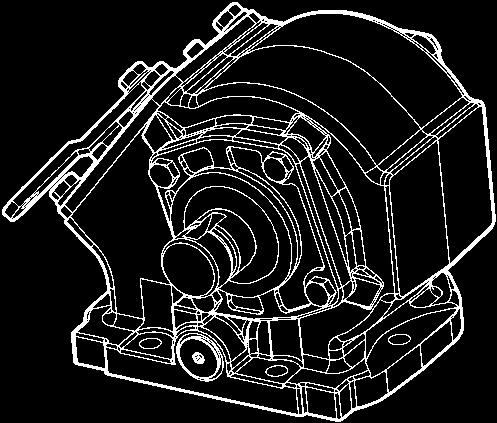
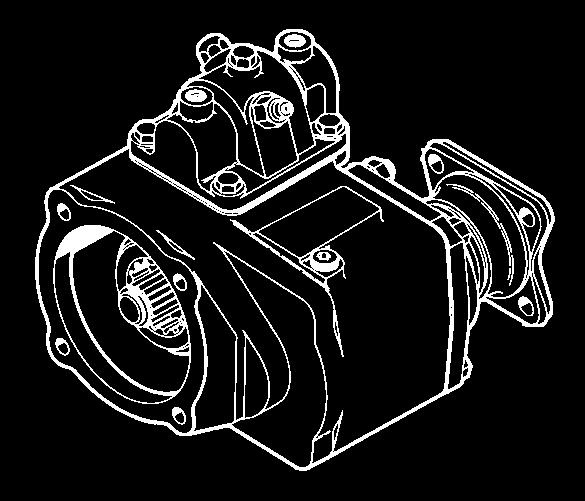
4 Exploded View 1
5 Bill of Materials Item Part Number Description Quantity P-557X Housing, Standard Mount ( X, G & K ) (Includes Item 23) P-558X Housing, Deep Mount ( Z & L ) (Includes Item 23) P-552X Housing, Standard Mount (Includes Item 23) P-562X Housing, Deep Mount (Includes Item 23) See Charts, Pgs 9-12 Gear, Output See Charts, Pgs Shaft, Output Pump Mount P-202 Shaft, Output ( XD ) Standard 1.250" Rd.313" KW P-978 Shaft, Output ( XD for B Ratio Only) Standard 1.250" Rd.313" KW Lockring (All other shifter types Except M ) Bearing Cone Bearing Cone P Gasket, Bearing Cap (.010")... A.R. A.R. A.R. 22-P Gasket, Bearing Cap (.020")... A.R. A.R. A.R. 22-P Gasket, Bearing Cap (.015")... A.R. A.R. A.R X Bearing Cap Assembly, Close End N.S Bearing Race X Bearing Cap Assembly, Open End ( XD Output) N.S Bearing Race See Charts, Pgs Bearing Cap Assembly, Pump Mounts Capscrew, Hex Head (.312" - 18 x 1.00") (Closed Cap Side) A Capscrew, Socket Head (.312" - 18 x 1.00") ( XD Output)) P-216 Oil Seal, XD Output See Charts, Pgs Oil Seal Key, Woodruff ( XD Output) See Charts, Pgs 9-12 Gear, Input See Charts, Pgs 9-12 Gear, Input Ratio Lock Ring Bearing Cone A Bearing Cone, Tapered ( A, B & C Only) A 14-P-75 Spacer, Input Bearing ( A, B & C Only) A Bearing, Needle Roller ( A, B & C Only) P-73-1 Spacer, Idler Gear (.149" -.151")... A.R. A.R. A.R. 14-P-73-2 Spacer, Idler Gear (.152" -.154")... A.R. A.R. A.R. 14-P-73-3 Spacer, Idler Gear (.155" -.157")... A.R. A.R. A.R P-102 Thrust Washer, Bearing P-88 Shaft, Idler Standard P-89 Shaft, Idler Pressure Lube ( P ) P-191 O-Ring Plug, O-Ring w/socket Face (NWD Plug) Roll Pin, Deep Mount (1" Long) Roll Pin, Standard Mount (1.125" Long) Cable Control Cover Assemblies Ratios Q, W & X X Shifter Cover Ass y, Wire Control (Ass y 3 & 6) X Shifter Cover Ass y, Wire Control (Ass y 4 & 5) Ratios F, H, L, R, S & U X Shifter Cover Ass y, Wire Control (Ass y 3 & 6) X Shifter Cover Ass y, Wire Control (Ass y 4 & 5) Ratios A, B & C X Shifter Cover Assembly, Wire Control (Ass y 3 & 6) X Shifter Cover Assembly, Wire Control (Ass y 4 & 5) N.S. Not Shown A.R. As Required Continued on Next Page See Pages for Kit Bill of Materials 2
6 Bill of Materials Item Part Number Description Quantity Ratios Q & W X Shifter Cover Assembly, Wire Control (Ass y 3 & 6) X Shifter Cover Assembly, Wire Control (Ass y 4 & 5) Ratios R, S & U X Shifter Cover Assembly, Wire Control (Ass y 3 & 6) X Shifter Cover Assembly, Wire Control (Ass y 4 & 5) All the above shift cover assemblies include items 24 thru P-39 Cover Plate, Shifter - Constant Mesh P-74 Cover Plate, Shifter P-19 Spring P-16 Poppet Pin P-191 O-Ring Ratios Q & W & X X Post and Plate Assembly, (Ass y 3 & 6) X Post and Plate Assembly, (Ass y 4 & 5) Ratios F, H, L, R, S & U X Post and Plate Assembly, (Ass y 3 & 6) X Post and Plate Assembly, (Ass y 4 & 5) Ratios A, B & C X Post and Plate Assembly, (Ass y 3 & 6) X Post and Plate Assembly, (Ass y 4 & 5) Flat Washer P-22 Shifter Lever Flat Washer Lockwasher Capscrew, Hex Head (.312" - 24 x.625") Indicator Switch, Pin Style (Normally Off) Indicator Switch, Pin Style (Normally On) P-8 Gasket, Shifter Cover A 5-A-188 Gasket, Shifter Cover ( A, B & C Ratio Only) B 35-P-8 Gasket, Shifter Cover ( A, B & C Ratio Only) Capscrew, Hex Head (.312" - 18 x.875") (Wire, Electric & Air Shift) Capscrew, Hex Head (.312" - 18 x 1.000") (Wire Shift A, B & C Ratio) 4-4 N.S. 68-P-2 Name Plate N.S Drive Screw, Name Plate Loose Parts P.T.O. Mounting Kit X Mounting Kit ( X Mounting Type) X Mounting Kit ( Z Mounting Type) X Mounting Kit ( G Metric Mounting Type) X Mounting Kit ( G Metric Mounting Type) X Mounting Kit ( X & Z Mounting) X Cable, Wire Control ( W Shifter) X Parts Bag, Wire Control ( W Shifter) X Bracket Kit, Wire Control ( C Shifter) N.S. Not Shown A.R. As Required Continued on Next Page See Pages for Kit Bill of Materials 3
7 Bill of Materials Item Part Number Description Quantity Air Shift Installation Kit X Air Shift Installation Kit ( A Shifter) X Air Shift Installation Kit ( P Shifter) X Air Shift Installation Kit ( Q Shifter) X Air Shift Installation Kit ( S Shifter) X Air Shift Installation Kit ( T Shifter) X Installation Kit ( C, H, W, X, Y ) Indicator Switch Booth X Gasket and Installation Instructions X Gasket and Installation Instructions X Electric Shift Installation Kit Booted Connector ( V Shifter Option) Pressure Protection Valve ( V Shifter Option) X Pressure Lube Hose ( HVP Input Gear Only) X Pump Mounting Kit ( XR Output) Service Kits X Indicator Switch Connector Service Kit X Indicator Switch Service Kit X Bearing Cap and Seal Assembly (Pressure Lube) See Pgs Pump Field Conversion Kit X Gasket & Seal Kit Lockring X Gasket & Seal Kit X Gasket & Seal Kit X Shifter Cover Seal Kit (Wire Control) X Shifter Cover Seal Kit (Wire Control A, B & C Ratio) X Shifter Cover Seal Kit (Air Shift) X Field Conversion Kit (Self Lube Replace 3-P-202) X Field Conversion Kit (Self Lube Replace 3-P-282) X Bearing and Spacer Kit (Non-Pressure Lube) X Bearing and Spacer Kit (Pressure Lube) X Bearing and Spacer Kit (Non-Pressure Lube A, B & C Ratio) X Bearing and Spacer Kit (Pressure Lube A, B & C Ratio) X Conversion Kit, 440 to 442 Series X Conversion Kit, 440 Deep Mount to 442 Deep Mount X Conversion Kit, 488 to 489 Series X Conversion Kit, 488 Deep Mount to 489 Deep Mount N.S. Not Shown A.R. As Required Continued on Next Page See Pages for Kit Bill of Materials 4
8 Air Control Parts ( A Designator) Item Part Number Description Quantity X Shifter Cover Assembly, Air Shift (Includes Items 48-57) X Shifter Cover Assembly, Air Shift P-130 Shifter Cover Snap Ring Cover Plug P-42 O-Ring P-21 Shifter Spring P-75 Shaft, Shifter P-41 O-Ring P-180 Shifter Fork Capscrew, Socket Head w/lockpatch (.312" - 18 x.750") Indicator Switch (Normally OFF) Push Connect, for 1/4" tubing P-8 Gasket, Shifter Cover Capscrew, Hex Head (.312" - 18 x.875") Air Shift Conversion Kits X Lever or Cable to Air X Lever or Cable to Electric/Air, 12V X Lever or Cable to Electric/Air, 24V X Wire to Air X Wire to Electric/Air 12V X Wire to Electric/Air 24V See Pages for Kit Bill of Materials 5
9 Shifter Kits For P.T.O. s ordered without the shifter (Shifter Type H ), the kits shown below will provide all the components required to complete the assembly. Part Number Description Quantity X Shifter Kit (Air Shift, A Shift Option) X Shifter Kit (Air Shift, P Shift Option) X Shifter Kit (Air Shift, Q Shift Option) X Shifter Kit (Air Shift, A Shift Option) X Shifter Kit (Air Shift, P Shift Option) X Shifter Kit (Air Shift, Q Shift Option) X Shifter Kit (Wire Control 3 & 6, Q, W, X Ratio; W Shift Option) X Shifter Kit (Wire Control 4 & 5, Q, W, X Ratio; W Shift Option) X Shifter Kit (Wire Control 3 & 6, Q, W, X Ratio; X Shift Option) X Shifter Kit (Wire Control 4 & 5, Q, W, X Ratio; X Shift Option) X Shifter Kit (Wire Control 3 & 6, F, L, R, S, U Ratio; W Shift Option) X Shifter Kit (Wire Control 4 & 5, F, L, R, S, U Ratio; W Shift Option) X Shifter Kit (Wire Control 3 & 6, F, L, R, S, U Ratio; X Shift Option) X Shifter Kit (Wire Control 4 & 5, F, L, R, S, U Ratio; X Shift Option) X Shifter Kit (Wire Control 3 & 6, Q & W Ratio; W Shift Option) X Shifter Kit (Wire Control 4 & 5, Q & W Ratio; W Shift Option) X Shifter Kit (Wire Control 3 & 6, Q & W Ratio; X Shift Option) X Shifter Kit (Wire Control 4 & 5, Q & W Ratio; X Shift Option) X Constant Mesh Kit X Shifter Kit (Wire Control 3 & 6, A, B & C Ratio; W Shift Option) X Shifter Kit (Wire Control 4 & 5, A, B & C Ratio; W Shift Option) X Shifter Kit (Wire Control 3 & 6, A, B & C Ratio; X Shift Option) X Shifter Kit (Wire Control 4 & 5, A, B & C Ratio; X Shift Option) X Shifter Kit ( V Shift Option) X Shifter Kit ( V Shift Option) X Field Conversion Kit (Shifter Shaft) See Pages for Kit Bill of Materials 6
10 Constant Mesh Parts ( M Designator) Lockring Lockring 83 Input Ratio Gear 83 Input Ratio Gear 442 & 489 Series Ass y 4 & & 489 Series Ass y 3 & Series Ass y 3 & Series Ass y 4 & 6 Item Part Number Description Quantity See Charts, Pg 9-12 Gear, Output See Charts, Pg 9-12 Gear, Input P-177 Spacer, Drive Shaft P-178 Spacer, Drive Shaft Lockring (Shifter Type M ) P-165 Spacer, Drive Shaft N.S. 34-P-39 Cover Plate, Shifter N.S. 35-P-8 Gasket, Shifter Cover N.S Capscrew, Hex Head (.312" - 18 x.625") N.S. Not Shown 7
11 Self Lube Parts NOTE: Pump must rotate in direction of arrow NOTE: Install Street Elbow into idler shaft before installing idler shaft Pump assembly as shown is for Q, W and X Ratios. Rotate as needed for A, C, F, H, L, R, S and U Ratios. Item Part Number Description Quantity Capscrew, Hex Head (.312" - 18 x 1.00") P-857 Shaft, Output ( LD Output) P-858 Shaft, Output ( LA, LB, LC, LE, LF Output) X Lube Pump & Bearing Cap Assembly X Pressure Lube Hose Assembly Street Elbow, See Pages for Kit Bill of Materials 8
12 Gear Chart 442 Series Input Gear Chart 442 Series Model Part Gear No. Teeth No. Teeth Number Number Type Input Gear Ratio Gear 442**AB 5-P-1001 SPUR **AC 5-P-1002 SPUR **AG 5-P-1003 SPUR **AH 5-P-1004 SPUR **AL (OBS) 5-P-1005 SPUR **AP 5-P-1006 Left Helix **AQ 5-P-1007 Left Helix **AR 5-P-1008 Left Helix **AW 5-P-1009 Left Helix **AX 5-P-1010 Left Helix **BA 5-P-1011 Left Helix **BC 5-P-1012 Left Helix **BE (OBS) 5-P-1013 SPUR **BG 5-P-1015 Left Helix **BH 5-P-1016 Right Helix **BJ 5-P-1017 Left Helix **BK 5-P-1018 Left Helix **BL 5-P-1019 Right Helix **BM 5-P-1020 Left Helix **BN 5-P-1021 Left Helix **BP 5-P-1022 Right Helix **BQ 5-P-1023 Left Helix **BR 5-P-1024 Right Helix **BS 5-P-1025 Left Helix **BU (OBS) 5-P-1026 SPUR **BY 5-P-1027 Right Helix **BZ 5-P-1028 Left Helix **CB 5-P-1029 Left Helix **CD 5-P-1031 Left Helix **CM (OBS) 5-P-1035 SPUR **CR 5-P-1036 Left Helix **DA 5-P-1037 SPUR **DB 5-P-1038 SPUR **DC 5-P-1039 SPUR **DD 5-P-1040 SPUR **DH 5-P-1041 Left Helix **DJ 5-P-1042 Left Helix **DK 5-P-1043 Left Helix **DM 5-P-1045 Left Helix **DN 5-P-1046 Left Helix **DP 5-P-1047 Left Helix **DQ 5-P-1048 Left Helix **DU 5-P-1050 Left Helix **DX 5-P-1052 Left Helix **DY (OBS) 5-P-1053 Left Helix **EA 5-P-1054 Left Helix **EC 5-P-1055 Left Helix **ED 5-P-1056 Left Helix **EL 5-P-1075 Right Helix **EP 5-P-1057 Right Helix **EQ 5-P-1058 Left Helix **ES 5-P-1059 Left Helix **EV 5-P-1060 SPUR 40 Model Part Gear No. Teeth No. Teeth Number Number Type Input Gear Ratio Gear 442**EW 5-P-1061 Left Helix **FB (OBS) 5-P-1063 Left Helix **FC 5-P-1064 Left Helix **FE 5-P-1065 Left Helix **FF (OBS) 5-P-1066 Left Helix **FK 5-P-1067 Left Helix **FL 5-P-1068 Left Helix **FM 5-P-1069 SPUR **FN 5-P-1070 Left Helix **FP 5-P-1071 Left Helix **FQ (OBS) 5-P-1072 Left Helix **FW 5-P-1098 Left Helix **GQ 5-P-1150 Left Helix **GS 5-P-1152 Left Helix **GR (OBS) 5-P-1157 SPUR **HW 5-P-1235 SPUR **HX 5-P-1236 SPUR **HY 5-P-1237 Left Helix **JA 5-P-1243 Left Helix **IT Assembled Without Input Gear 442**JD 5-P-1248 Left Helix **JG 5-P-1256 Left Helix **JH 5-P-1257 Left Helix **JK 5-P-1261 Left Helix **JM 5-P-1263 Left Helix **JP 5-P-1268 Left Helix **JS 5-P-1310 Left Helix **JT (OBS) 5-P-1313 Left Helix **JU 5-P-1316 Left Helix **JW 5-P-1319 Left Helix **KC 5-P-1341 Left Helix **KH 5-P-1343 Left Helix **KJ 5-P-1405 Left Helix 33 (C1) 442**KL 5-P-1407 Left Helix 29 (C2) 442**KN 5-P-1383 Left Helix 27 (D1) 442**KX 5-P-1411 Left Helix 26 Input Gears A Ratio Only 442*AAB 5-P-1279 SPUR *AAH 5-P-1280 SPUR *AAP 5-P-1282 Left Helix *AAR 5-P-1283 Left Helix *ADA 5-P-1284 SPUR *AES 5-P-1285 Left Helix *AJA 5-P-1366 Left Helix Input Gears B Ratio Only 442*BHV 5-P-1358 SPUR *BAH 5-P-1418 SPUR Input Gears C Ratio Only 442*CAB 5-P-1286 SPUR *CAH 5-P-1287 SPUR *CJA 5-P-1368 Left Helix *CAP 5-P-1289 Left Helix *CAR 5-P-1290 Left Helix *CDA 5-P-1291 SPUR *CES 5-P-1292 Left Helix Input Gears F Ratio Only 442*FAB 5-P-1076 SPUR *FAH 5-P-1077 SPUR *FAP 5-P-1079 Left Helix Continued on Next Page 9
13 Gear Chart 442 Series Input Gear Chart 442 Series (Continued) Model Part Gear No. Teeth No. Teeth Number Number Type Input Gear Ratio Gear 442*FAR 5-P-1080 Left Helix *FBC 5-P-1081 Left Helix *FBG 5-P-1082 Left Helix *FBM 5-P-1083 Left Helix *FBQ 5-P-1084 Left Helix *FDA 5-P-1085 SPUR *FDJ 5-P-1086 Left Helix *FDN 5-P-1087 Left Helix *FDU 5-P-1088 Left Helix *FEC 5-P-1089 Left Helix *FED 5-P-1090 Left Helix *FEP 5-P-1091 Right Helix *FES 5-P-1092 Left Helix *FET 5-P-1093 Left Helix *FEV 5-P-1094 SPUR *FEW 5-P-1095 Left Helix Input Ratio Gear Chart 442 Series Ratio Part Number No. Teeth B 442*L 5-P *Q 5-P *R 5-P *S 5-P *U 5-P *W 5-P *X 5-P Geared Adapter Gears 442 Series Model Part Gear No. Teeth No. Teeth Number Number Type Input Gear Ratio Gear 442*FFE 5-P-1096 Left Helix *FFN 5-P-1097 Left Helix *FGQ 5-P-1149 Left Helix *FGS 5-P-1151 Left Helix *FHV (H) 5-P-1300 SPUR *FJS 5-P-1311 Left Helix *FJT 5-P-1314 Left Helix *FJU 5-P-1317 Left Helix *FJW 5-P-1320 Left Helix *FJA 5-P-1340 Left Helix Input Gears H Ratio Only 442*HAH 5-P-1364 SPUR *HDA 5-P-1365 SPUR *HJA 5-P-1342 Left Helix Output Gear Chart 442 Series Ratio Part Number No. Teeth C 442*A 2-P *B 2-P *C 2-P *F 2-P *H 2-P *L 2-P *Q 2-P *R 2-P *S 2-P *U 2-P *W 2-P *X 2-P Model Part Gear No. Teeth Adapter Input Part Gear No. Teeth Number Number Type Gear Number Type 442**GX 5-P-1183 Right Helix 21 AP 5-P-1006 Left Helix **GY 5-P-1184 Right Helix 21 AR 5-P-1008 Left Helix **GZ 5-P-1185 Right Helix 22 AW 5-P-1009 Left Helix **HA 5-P-1186 Left Helix 22 AX 5-P-1010 Right Hand **HB 5-P-1187 Right Helix 23 BG 5-P-1015 Left Helix **HC 5-P-1188 Right Helix 22 BM 5-P-1020 Left Helix **HD 5-P-1189 Right Helix 25 CB 5-P-1029 Left Helix **HE 5-P-1190 Right Helix 27 CD 5-P-1031 Left Helix **HF 5-P-1191 Right Helix 17 DM 5-P-1045 Left Helix **HG 5-P-1192 Right Helix 19 DN 5-P-1046 Left Helix **HH 5-P-1193 Right Helix 28 DU 5-P-1050 Left Helix **HJ 5-P-1194 Right Helix 36 EC 5-P-1055 Left Helix **HK 5-P-1195 Right Helix 34 ED 5-P-1056 Left Helix **HL 5-P-1196 Right Helix 22 ES 5-P-1059 Left Helix **HM 5-P-1197 Right Helix 20 EW 5-P-1061 Left Helix **HP 5-P-1199 Right Helix 26 FC 5-P-1064 Left Helix **HQ 5-P-1200 Right Helix 29 FE 5-P-1065 Left Helix **HR 5-P-1201 Right Helix 26 FN 5-P-1070 Left Helix **JB 5-P-1244 Right Helix 26 HY 5-P-1237 Left Helix **JC 5-P-1247 Right Helix 27 DJA 5-P-1243 Left Helix **JE 5-P-1249 Right Helix 20 JD 5-P-1248 Left Helix **JL 5-P-1262 Right Helix 24 JK 5-P-1261 Left Helix **JN 5-P-1264 Right Helix 22 JM 5-P-1263 Left Helix **JQ 5-P-1269 Right Helix 33 JP 5-P-1268 Left Helix 33 Continued on Next Page 10
14 Gear Chart 442 Sereis & 447Series Geared Adapter Gears 442 Series Model Part Gear No. Teeth Adapter Input Part Gear No. Teeth Number Number Type Gear Number Type 442**JY 5-P-1312 Right Helix 20 JS 5-P-1310 Left Helix **KA 5-P-1318 Right Helix 25 JU 5-P-1316 Left Helix **KB 5-P-1321 Right Helix 23 JW 5-P-1319 Left Helix **KK 5-P-1406 Right Helix 33 KJ 5-P-1405 Left Helix **KM 5-P-1408 Right Helix 29 KL 5-P-1407 Left Helix **KP 5-P-1384 Right Helix 27 KN 5-P-1383 Left Helix 27 Gear Chart 447 Series Model Part No. Helix No. Teeth* No. Teeth** Part No. No. Teeth Number Input Gear Angle Input Gear Ratio Gear Output Gear Output Gear 447*QET 5-P-865 Left Helix P *QES 5-P-869 Left Helix P *QFX 5-P-979 Left Helix P *QGP 5-P-1145 Spur P *QCD 5-P-1178 Left Helix P *QEV 5-P-1205 Spur P *SET 5-P-866 Left Helix P *SES 5-P-870 Left Helix P *SFF 5-P-891 Left Helix P *SEQ 5-P-892 Left Helix P *SCD 5-P-1179 Left Helix P *SEV 5-P-1206 Spur P *SJX 5-P-1270 Spur P *RET 5-P-1215 Left Helix P *RES 5-P-1216 Left Helix P *RGP 5-P-1217 Spur P *RCD 5-P-1218 Left Helix P *REV 5-P-1219 Spur P *UET 5-P-867 Left Helix P *UES 5-P-871 Left Helix P *UFE 5-P-889 Left Helix P *UGP 5-P-1147 Spur P *UCD 5-P-1180 Left Helix P *UEV 5-P-1207 Spur P *UJX 5-P-1271 Spur P *WET 5-P-868 Left Helix P *WES 5-P-872 Left Helix P *WFE 5-P-890 Left Helix P GWFH 5-P-900 Right Helix P GWFG 5-P-901 Right Helix P *WFY 5-P-976 Spur P *WGD 5-P-988 Right Helix P *WGP 5-P-1148 Spur P *WCD 5-P-1181 Left Helix P *WEV 5-P-1208 Spur P *WJX 5-P-1272 Spur P * Input gear meshes with the transmission ** Ratio gear meshes with the P.T.O. Output Gear NOTE: The unique design of the 447 Series input gear requires that the spacers used to shim the input bearings be placed opposite of the normal position found on the 442 and 489 series. For the 447 Series install the Input gear spacers (item # 18 on pg. 2) on the idler shaft between the Input Gear and P.T.O. housing. 11
15 Gear Chart 489 Series Input Gear Chart 489 Series Model Part Gear No. Teeth No. Teeth Number Number Type Input Gear Ratio Gear 489**AB 5-P-1001 Spur **AH 5-P-1004 Spur **AR 5-P-1008 Left Helix **BG 5-P-1015 Left Helix **DA 5-P-1037 Spur **DU 5-P-1050 Left Helix **EV 5-P-1060 Spur **DB 5-P-1038 Spur **CR 5-P-1036 Left Helix **HW 5-P-1235 Spur **HX 5-P-1236 Spur *AAB 5-P-1279 Spur *AAH 5-P-1280 Spur *AAR 5-P-1283 Left Helix *ADA 5-P-1284 Spur Model Part Gear No. Teeth No. Teeth Number Number Type Input Gear Ratio Gear 489*CAB 5-P-1286 Spur *CAH 5-P-1287 Spur *CAR 5-P-1290 Left Helix *CDA 5-P-1291 Spur *FAB 5-P-1076 Spur *FAH 5-P-1077 Spur *FAR 5-P-1080 Left Helix *FBG 5-P-1082 Left Helix *FDA 5-P-1085 Spur *FDU 5-P-1088 Left Helix *FEV 5-P-1094 Spur *HAH 5-P-1364 Spur *HDA 5-P-1365 Spur Ratio Gear Chart 489 Series Input Ratio Gear Chart 489 Series Output Gear Chart 489 Series Ratio Part Number No. Teeth Ratio Part Number No. Teeth 489*A See Chart Above 489*A 2-P *C See Chart Above 489*C 2-P *F See Chart Above 489*F 2-P *H See Chart Above 449*H 2-P *L 5-P *L 2-P *Q 5-P *Q 2-P *R 5-P *R 2-P *S 5-P *S 2-P *U 5-P *U 2-P *W 5-P *W 2-P *X 5-P *X 2-P
16 Direct Mount Pump Conversion Kits Flange Suffix Flange Type Shaft Type Conversion Kit AA Special for England.982" - 6 Spline AF S.A.E. B 2 or 4-Bolt 1.0" - 15 Spline XD to AF X AK S.A.E. B 2-Bolt 7/8" - 13 Spline XD to AK X ( B Ratio Only) XD to AK X AZ Non-Standard 1-1/4" - 14 Spline XD to AZ X FF S.A.E. B 2 or 4-Bolt 7/8" Rd w/1/4" Key XD to FF X GA Rotatable S.A.E. B 2-Bolt 7/8" - 13 Spline XD to GA X XR to GA X RA to GA X GB Rotatable S.A.E. B 4-Bolt 7/8" - 13 Spline XD to GB X XR to GB X RB to GB X GF S.A.E. BB 2 or 4-Bolt 1.0" - 15 Spline XD to GF X AF to GF X GH Rotatable S.A.E. BB 2-Bolt 1.0" - 15 Spline XD to GH X RF to GH X GJ S.A.E. B 4-Bolt Rotatable 1.0" - 15 Spline XD to GJ X RE to GJ X GK S.A.E. B 2 or 4-Bolt 7/8" - 13 Spline XD to GK X XK to GK X GP S.A.E. A Pilot 2 or 4-Bolt 7/8" - 13 Spline XD to GP X XP to GP X GQ S.A.E. B 2 or 4-Bolt 7/8" - 13 Spline XD to GQ X XQ to GQ X GR CHELSEA SPECIAL 4-Bolt 7/8" - 13 Spline XD to GR X GY DIN 5462 Pump Mounting 7/8" - 13 Spline XD to GY X XY to GY X GZ Non-Standard 4-Bolt 1-1/4" - 14 Spline XD to GZ X AZ to GZ X LA S.A.E. B 2-Bolt 7/8" - 13 Spline AK to LA X LB S.A.E. A Pilot 2-Bolt 7/8" - 13 Spline XP to LB X LC S.A.E. B 2 or 4-Bolt 7/8" - 13 Spline XQ to LC X LD Similar to XD 1-1/4" Rd XD to LD LE 6-Bolt Rd 7/8" - 13 Spline XN to LE X LF S.A.E. B 2 or 4-Bolt 7/8" - 13 Spline XK to LF X NOTE: Check Current Price Sheet for Availability of Output Options XR to XK Conversion Flange 21-P-525 Shaft with Grease Fitting Similar to Ass y XK Flange Rotated 90 Lube Pump Option Continued on Next Page 13
17 Direct Mount Pump Conversion Kits (Cont'd) Flange Suffix Flange Type Shaft Type Conversion Kit PA Parker P2-060 Pump Mounting 7/8" - 13 Spline XD to PA X PF Parker P2-060 Pump Mounting 1.0" - 15 Spline XD to PF X RA Rotatable S.A.E. B 2-Bolt 7/8" - 13 Spline XD to RA X XR to RA X ( B Ratio Only) XD to RA X RB Rotatable S.A.E. B 4-Bolt 7/8" - 13 Spline XD to RB X XR to RB X ( B Ratio Only) XR to RB X RC Rotatable S.A.E. A 2-Bolt 5/8" - 9 Spline XD to RC X RD Rotatable S.A.E. A 2-Bolt 7/8" - 13 Spline XD to RD X ( B Ratio Only) XD to RD X RE S.A.E. B 4-Bolt Rotatable 1.0" - 15 Spline XD to RE X RF Rotatable S.A.E. B 2-Bolt 1.0" - 15 Spline XD to RF X RY Rotatable DIN 5462 DIN 5462 XD to RY X SQ S.A.E. B 4-Bolt 7/8" - 13 Spline XD to SQ X ( B Ratio Only) XD to SQ X XE S.A.E. A 2 or 4-Bolt 5/8" - 9 Spline XD to XE X XG Non-Standard-S.A.E. A 2-Bolt 3/4" Rd w/3/16" Key XD to XG X XJ Non-Standard 2-Bolt 3/4" Rd XD to XJ X XK S.A.E. B 2 or 4-Bolt 7/8" - 13 Spline XD to XK X ( B Ratio Only) XD to XK X XL Non-Standard 2-Bolt 7/8" - 13 Spline XD to XL X ( B Ratio Only) XD to XL X XO S.A.E. A Pilot 2-Bolt 3/4" Rd w/3/16" Key XD to XO X XP S.A.E. A Pilot 2-Bolt 7/8" - 13 Spline XD to XP X ( B Ratio Only) XD to XP X XQ S.A.E. B 2 or 4-Bolt 7/8" - 13 Spline XD to XQ X ( B Ratio Only) XD to XQ X XR CHELSEA SPECIAL 4-Bolt 7/8" - 13 Spline XD to XR X XV Rd Shaft 1-1/4" w/set Screw XD to XV X XX S.A.E Tapered Shaft 1-1/4" w/5/16" Key XD to XX X XY DIN 5462 Pump Mounting DIN 5462 XD to XY X NOTE: Check Current Price Sheet for Availability of Output Options XR to XK Conversion Flange 21-P-525 Shaft with Grease Fitting Similar to Ass y XK Flange Rotated 90 Lube Pump Option 14
18 Output Options Bill of Materials Output Shaft Lockring Flange Assembly Gasket Oil Seal Hex Socket Head Screw Output Part Number Description Qty Flange AA 3-P-862 Output Shaft P-216 Oil Seal X Bearing Cap Ass y (21-P-532) Socket Head Capscrew (.312" - 18 x 1.5")... 4 AF 3-P-854 Output Shaft P-219 Oil Seal X Bearing Cap Ass y (21-P-522) Socket Head Capscrew (.312" - 18 x 2.0")... 4 AK 3-P-282 Output Shaft P-979 Output Shaft ( B Ratio Only) P-216 Oil Seal X Bearing Cap Ass y (21-P-472) Socket Head Capscrew (.312" - 18 x 1.5")... 4 AZ 3-P-844 Output Shaft P-275 Oil Seal X Bearing Cap Ass y (21-P-508) Socket Head Capscrew (.312" - 18 x 2.5")... 4 FF 3-P-851 Output Shaft P-219 Oil Seal X Bearing Cap Ass y (21-P-522) Socket Head Capscrew (.312" - 18 x 2.0")... 4 (1) G* 3-P-923X GA, GB, GR, Shaft Assemblies... 1 or 3-P-981X GE Shaft Assembly... 1 or 3-P-921X GF Shaft Assemblies... 1 or 3-P-933X GQ, GK, GP Shaft Assemblies... 1 or 3-P-938X GY Shaft Assemblies... 1 or 3-P-939X GZ Shaft Assemblies... 1 or 3-P-941X GH, GJ Shaft Assemblies Lube Fitting (Zerk) Grease Fitting Cap Coupling Lube Pack (5/8 fl.oz) P-268 Rear Bearing Cap Shaft Oil Seal X Rear Bearing Cap Assembly Rear Bearing Cap Hex Head Capscrew (.312" - 18" x 1.0")... 4 L* 3-P-857 Output Shaft ( LD ) P-858 Output Shaft ( LA, LB, LC, LF ) X Lube Pump & Bearing Cap Ass y X Pressure Lube Hose Ass y Elbow 90 Street Hex Capscrew (.312" - 18 x 1.0")... 4 Continued on following page (1) NOTE: For Output Flange Information see the related flange Bills of Material: GA=RA, GB=RB, GF=AF, GR=XR, GK=XK, GP=XP, GQ=XQ, GY=XY, GZ=AZ, GH=RF, GJ=RE & GE=XE 15
19 Output Options Bill of Materials Output Flange Part Number Description Qty PA 3-P-283 Output Shaft P-216 Oil Seal X Bearing Cap Ass y (21-P-574) P-661 Pump Flange Socket Head Capscrew (.312" - 18 x 1.0") X Capscrew Bag Kit Socket Head Capscrew (.312" - 18 x 1.0")... 3 PF 3-P-924 Output Shaft P-219 Oil Seal X Bearing Cap Ass y (21-P-629) P-661 Pump Flange Socket Head Capscrew (.312" - 18 x 1.0") P-271 O-Ring... 1 RA 3-P-283 Output Shaft P-980 Output Shaft ( B Ratio Only) P-216 Oil Seal X Bearing Cap Ass y (21-P-574) P-628 Pump Flange (Ship Loose w/unit) Socket Head Capscrew X Capscrew Bag Kit Socket Head Capscrew... 3 RB 3-P-283 Output Shaft P-980 Output Shaft ( B Ratio Only) P-216 Oil Seal X Bearing Cap Ass y (21-P-574) P-572 Pump Flange (Ship Loose w/unit) Socket Head Capscrew X Capscrew Bag Kit Socket Head Capscrew... 3 RC 3-P-800 Output Shaft P-216 Oil Seal X Bearing Cap Ass y (21-P-640) P-638 Pump Flange Socket Head Capscrew (.312" - 18 x 1.0") X Capscrew Bag Kit Socket Head Capscrew (.312" - 18 x.75")... 6 RE 3-P-924 Output Shaft P-219 Oil Seal X Bearing Cap Ass y (21-P-629) P-654 Pump Flange Socket Head Capscrew (.312" - 18 x 1.0") P-271 O-Ring... 1 RF 3-P-924 Output Shaft P-219 Oil Seal X Bearing Cap Ass y (21-P-629) P-626 Pump Flange Socket Head Capscrew (.312" - 18 x 1.0") P-271 O-Ring... 1 RY 3-P-768 Output Shaft P-625 Pump Flange X Bearing Cap Ass y (21-P-532) Socket Head Capscrew (.312" - 18 x 1.5") X Standard Loose Parts Kit Socket Head Capscrew (M10 1.5" x.984") P-100 Gasket P-84 Gasket Pipe Plug... 2 Continued on following page 16
20 Output Options Bill of Materials Output Part Number Description Qty Flange XE 3-P-800 Output Shaft P-216 Oil Seal X Bearing Cap Ass y (21-P-161) Socket Head Capscrew (.312" - 18 x 1.5")... 4 XG 3-P-281 Output Shaft P-216 Oil Seal X Bearing Cap Ass y (21-P-259) Socket Head Capscrew (.312" - 18 x 1.5")... 4 XJ 3-P-284 Output Shaft P-216 Oil Seal X Bearing Cap Ass y (21-P-259) Socket Head Capscrew (.312" - 18 x 1.5")... 4 XK 3-P-282 Output Shaft P-979 Output Shaft ( B Ratio Only) P-216 Oil Seal X Bearing Cap Ass y (21-P-424) & (28-P-216) Socket Head Capscrew (.312" - 18 x 1.5")... 4 XL 3-P-283 Output Shaft P-980 Output Shaft ( B Ratio Only) P-216 Oil Seal X Bearing Cap Ass y (21-P-259) Socket Head Capscrew (.312" - 18 x 1.5")... 4 XO 3-P-284 Output Shaft P-216 Oil Seal X Bearing Cap Ass y (21-P-161) Socket Head Capscrew (.312" - 18 x 1.5")... 4 XP 3-P-282 Output Shaft P-979 Output Shaft ( B Ratio Only) P-216 Oil Seal X Bearing Cap Ass y (21-P-161) Socket Head Capscrew (.312" - 18 x 1.5")... 4 XQ 3-P-282 Output Shaft P-979 Output Shaft ( B Ratio Only) P-216 Oil Seal X Bearing Cap Ass y (21-P-269) Socket Head Capscrew (.312" - 18 x 1.5")... 4 XR 3-P-283 Output Shaft P-216 Oil Seal X Bearing Cap Assembly (21-P-574) Hex Shoulder Screw (.312" - 24) Flat Washer X Pump Mounting Kit Washer Hex Lock Nut (.312" - 24)... 4 XV 3-P-202 Output Shaft P-216 Oil Seal P-978 Output Shaft ( B Ratio Only) X Bearing Cap Ass y (21-P-418) Hex Capscrew (.312" - 18 x 1.0") Woodruff Key Companion Flange Set Screw... 1 Continued on following page 17
21 Output Options Bill of Materials Output Flange Part Number Description Qty XX 3-P-766 Output Shaft P-216 Oil Seal Hex Capscrew (.312" - 18 x 1.0") Square Key Hex Locknut (1.0" - 20)... 1 XY 3-P-768 Output Shaft P-275 Oil Seal X Bearing Cap Ass y (21-P-614) Socket Head Capscrew (.312" - 18 x 1.0")... 4 SQ 3-P-282 Output Shaft P-979 Output Shaft ( B Ratio Only) P-216 Oil Seal X Bearing Cap Ass y (21-P-692) Socket Head Capscrew (.312" - 18 x 1.5")
22 P.T.O. Housing Dimensions P.T.O. Series Part Number CA CB 442/447 Standard 1-P-557X 0.793" 3.800" ( F, H, L, R, S, U ) 3.317" ( F, H, L, R, S, U ) 6.428" 7.000" 3.701" ( Q, W, X ) 3.087" ( Q, W, X ) 3.568" ( A, C ) 3.050" ( A, C ) 442/447 Deep Mount 1-P-558X 0.573" 3.580" ( F, H, L, R, S, U ) 3.317" ( F, H, L, R, S, U ) 6.207" 7.000" 3.481" ( Q, W, X ) 3.087" ( Q, W, X ) 3.348" ( A, C ) 3.050" ( A, C ) 489 Standard 1-P-552X 1.072" 4.079" ( F, H, L, R, S, U ) 3.317" ( F, H, L, R, S, U ) 6.708" 8.500" 3.980" ( Q, W, X ) 3.087" ( Q, W, X ) 3.847" ( A, C ) 3.050" ( A, C ) 489 Deep Mount 1-P-562X 0.930" 3.937" ( F, H, L, R, S, U ) 3.317" ( F, H, L, R, S, U ) 6.566" 8.500" 3.838" ( Q, W, X ) 3.087" ( Q, W, X ) 3.705" ( A, C ) 3.050" ( A, C ) CD CH CV Assembly Arrangements.500".500" ".500"
23 Pump Flange & Shaft Dimensions Pump Flange Suffix Bolt Circle Dia. Bolt Holes FC FD FE FF FH Tapped Hole No. Equally Spaced Female Pilot Dia. Pilot Depth Face to End of Shaft Face thru Hole Face to Center of P.T.O. Output Shaft Hole Diameter Keyway Width AA M10-1.5" N/A N/A N/A / Spline AF, GF " " - 15 Spline " AK " /8" - 13 Spline AZ, GZ " /4" - 14 Spline FF " /8" Rd 1/4" " MY, GM 3.15 x 3.15 M DIN 5462 PA /8" - 13 Spline PF " - 15 Spline RA, GA " /8" - 13 Spline RB, GB " /8" - 13 Spline RC " /8" - 9 Spline RD " /8" - 13 Spline RE, GJ 3.53 x " " - 15 Spline RF, GH " " - 15 Spline RY M " DIN 5462 XE " /8" - 9 Spline XG " /4" Rd 3/16" XJ " /4" Rd 3/16" XK, GK " /8" - 13 Spline " XL " /8" - 13 Spline XO " /4" Rd 3/16" " XP, GP " /8" - 13 Spline " XY, GY M " DIN 5462 XQ, GQ, SQ " /8" - 13 Spline " XR, GR " - 24(Studs) N/A N/A /8" - 13 Spline Rotatable Flange Rotates in 30 Increments Two Set of Holes Spaced 14 Apart Not Tapped NOTE: To convert an XR to an XK, use conversion flange number 21-P
24 Model Number Designation Basic Model 442 Mounting Type G = Standard Mount w/metric Studs K = Standard Mount Less Stud Kit L = Deep Mount Less Stud Kit X = Standard Mount Z = Deep Mount Gear Ratio A = 14/39 B = 14/39 C = 17/37 F = 21/37 H = 23/35 L = 25/34 Q = 19/24 R = 22/24 S = 24/22 U = 26/20 W = 26/17 X = 38/21 Input Gear Designator Lubrication X = No Pressure Lube P = Pressure Lube 442 X Q AB X Y 3 XD Output Type AK = S.A.E. B 2-Bolt 7/8" - 13T AF = S.A.E. BB 2 or 4-Bolt 1" - 15T AZ = S.A.E. B 4-Bolt 1-1/4" - 14T GA = Greaseable Rotatable B 2-Bolt 7/8" - 13T GB = Greaseable Rotatable B 4-Bolt 7/8" - 13T GF = Greaseable S.A.E. BB 2 or 4-Bolt 1" - 15T GH = Greaseable Rot. S.A.E. BB 2-Bolt 1" - 15T GK = Greaseable S.A.E. B 2 or 4-Bolt 7/8" - 13T GP = Greaseable S.A.E. B 2 or 4-Bolt 7/8" - 13T GQ = Greaseable S.A.E. B 2 or 4-Bolt 7/8" - 13T GR = Greaseable CHELSEA SPECIAL 7/8" - 13T GY = Greaseable DIN T GZ = Greaseable S.A.E. B 4-Bolt 1-1/4" - 14T LA = S.A.E. B 2-Bolt w/self Lube Pump 7/8" - 13T LB = S.A.E. A 2-Bolt w/self Lube Pump 7/8" - 13T LC = S.A.E. B 2 or 4-Bolt w/self Lube 7/8" - 13T LD = 1-1/4" Rd w/self Lube Pump LF = S.A.E. B 2 or 4-Bolt w/self Lube 7/8" - 13T PA = Rotatable S.A.E. B 2-Bolt for P2-060 Pump RA = Rotatable S.A.E. B 2-Bolt 7/8" - 13T RB = Rotatable S.A.E. B 4-Bolt 7/8" - 13T RC = Rotatable S.A.E. A 2-Bolt 5/8" - 9T RD = Rotatable S.A.E. A 2-Bolt 7/8" - 13T RE = Rotatable S.A.E. BB 4-Bolt 1" - 15T RF = Rotatable S.A.E. BB 2-Bolt 1" - 15T RY = Rotatable DIN T SQ = S.A.E. B 4-Bolt 7/8" - 13T XD = 1-1/4" Rd Standard Shaft XE = S.A.E. A 2 or 4-Bolt 5/8" - 9T XG = S.A.E. A 2-Bolt 3/4" Rd XJ = S.A.E. A 2-Bolt 3/4" Rd XK = S.A.E. B 2 or 4-Bolt 7/8" - 13T XQ = S.A.E. B 2 or 4-Bolt 7/8" - 13T XR = CHELSEA SPECIAL 7/8" - 13T XX = Tapered Output Shaft XY = DIN T Assembly Arrangement 3, 4, 5, 6 Shifter Type A = Air Shift C = Heavy Duty Bracket Less Cable H = No Wire Shift Cover M = Constant Mesh P = 12 Volt Electric/Air S = Combo Valve T = P.T.O. & Dump Pump Combo Valve Less Kick-out V = Air Shift Less Installation Kit W = Cable Shift X = Wire Less Cable & Knob 21
25 Model Number Designation 447 A U FY X A 5 XE Basic Model 447 Mounting Type Z = Deep Mounting G = Standard Mount w/metric Studs K = Standard Mount Less Stud Kit L = Deep Mount Less Stud Kit X = Standard Mounting Gear Ratio Q = 19/24 R = 22/24 S = 24/22 U = 26/20 W = 26/17 Input Gear Designator Lubrication X = No Lubrication P = Pressure Lube Output Type AK = S.A.E. B 2-Bolt 7/8" - 13T AF = S.A.E. BB 2 or 4-Bolt 1" - 15T AZ = S.A.E. B 4-Bolt 1-1/4" - 14T GA = Greaseable Rotatable B 2-Bolt 7/8" - 13T GB = Greaseable Rotatable B 4-Bolt 7/8" - 13T GF = Greaseable S.A.E. BB 2 or 4-Bolt 1" - 15T GH = Greaseable Rot. S.A.E. BB 2-Bolt 1" - 15T GK = Greaseable S.A.E. B 2 or 4-Bolt 7/8" - 13T GP = Greaseable S.A.E. B 2 or 4-Bolt 7/8" - 13T GQ = Greaseable S.A.E. B 2 or 4-Bolt 7/8" - 13T GR = Greaseable CHELSEA SPECIAL 7/8" - 13T GY = Greaseable DIN T GZ = Greaseable S.A.E. B 4-Bolt 1-1/4" - 14T LA = S.A.E. B 2-Bolt w/self Lube Pump 7/8" - 13T LB = S.A.E. A 2-Bolt w/self Lube Pump 7/8" - 13T LC = S.A.E. B 2 or 4-Bolt w/self Lube 7/8" - 13T LD = 1-1/4" Rd w/self Lube Pump LF = S.A.E. B 2 or 4-Bolt w/self Lube 7/8" - 13T RA = Rotatable S.A.E. B 2-Bolt 7/8" - 13T RB = Rotatable S.A.E. B 4-Bolt 7/8" - 13T RC = Rotatable S.A.E. A 2-Bolt 5/8" - 9T Rd = Rotatable S.A.E. A 2-Bolt 7/8" - 13T RE = Rotatable S.A.E. BB 4-Bolt 1" - 15T RF = Rotatable S.A.E. BB 2-Bolt 1" - 15T RY = Rotatable DIN T XD = 1-1/4" Rd Standard Shaft XE = S.A.E. A 2 or 4-Bolt 5/8" - 9T XG = S.A.E. A 2-Bolt 3/4" Rd XJ = S.A.E. A 2-Bolt 3/4" Rd XK = S.A.E. B 2 or 4-Bolt 7/8" - 13T XQ = S.A.E. B 2 or 4-Bolt 7/8" - 13T XR = CHELSEA SPECIAL 7/8" - 13T XX = Tapered Output Shaft XY = DIN T Assembly Arrangement 3, 4, 5, 6 Shifter Type A = Air Shift C = Heavy Duty Bracket Less Cable H = No Wire Shift Cover M = Constant Mesh P = 12 Volt Electric/Air V = Air Shift Less Installation Kit W = Cable Shift X = Wire Less Cable & Knob 22
26 Model Number Designation 489 X F AH X P 3 XD Basic Model 489 Mounting Type K = Standard Mount Less Stud Kit G = Standard Mount w/metric Stud Kit X = Standard Mount Z = Deep Mount Gear Ratio A = 14/39 C = 17/37 F = 21/37 H = 23/35 L = 25/34 Q = 19/24 R = 22/24 S = 24/22 U = 26/20 W = 26/17 X = 38/21 Input Gear Designator Lubrication X = No Lubrication P = Pressure Lube Shifter Type A = Air Shift C = Heavy Duty Bracket Less Cable H = No Wire Shift Cover M = Constant Mesh P = 12 Volt Electric/Air S = Combo Valve T = P.T.O. & Dump Pump Combo Valve Less Kick-out V = Air Shift Less Installation Kit W = Cable Shift X = Wire Less Cable & Knob Output Type AK = S.A.E. B 2-Bolt 7/8" - 13T AF = S.A.E. BB 2 or 4-Bolt 1" - 15T AZ = S.A.E. B 4-Bolt 1-1/4" - 14T GA = Greaseable Rotatable B 2-Bolt 7/8" - 13T GB = Greaseable Rotatable B 4-Bolt 7/8" - 13T GF = Greaseable S.A.E. BB 2 or 4-Bolt 1" - 15T GH = Greaseable Rot. S.A.E. BB 2-Bolt 1" - 15T GK = Greaseable S.A.E. B 2 or 4-Bolt 7/8" - 13T GP = Greaseable S.A.E. B 2 or 4-Bolt 7/8" - 13T GQ = Greaseable S.A.E. B 2 or 4-Bolt 7/8" - 13T GR = Greaseable CHELSEA SPECIAL 7/8" - 13T GY = Greaseable DIN T GZ = Greaseable S.A.E. B 4-Bolt 1-1/4" - 14T LA = S.A.E. B 2-Bolt w/self Lube Pump 7/8" - 13T LB = S.A.E. A 2-Bolt w/self Lube Pump 7/8" - 13T LC = S.A.E. B 2 or 4-Bolt w/self Lube 7/8" - 13T LD = 1-1/4" Rd w/self Lube Pump LF = S.A.E. B 2 or 4-Bolt w/self Lube 7/8" - 13T PA = Special S.A.E. B 2-Bolt 7/8" - 13 Spline PF = Special S.A.E. B 2-Bolt 1" - 15 Spline RA = Rotatable S.A.E. B 2-Bolt 7/8" - 13T RB = Rotatable S.A.E. B 4-Bolt 7/8" - 13T RC = Rotatable S.A.E. A 2-Bolt 5/8" - 9T RD = Rotatable S.A.E. A 2-Bolt 7/8" - 13T RE = Rotatable S.A.E. BB 4-Bolt 1" - 15T RF = Rotatable S.A.E. BB 2-Bolt 1" - 15T RY = Rotatable DIN T SQ = S.A.E. B 4-Bolt 7/8" - 13T XD = 1-1/4" Rd Standard Shaft XE = S.A.E. A 2 or 4-Bolt 5/8" - 9T XG = S.A.E. A 2-Bolt 3/4" Rd XJ = S.A.E. A 2-Bolt 3/4" Rd XK = S.A.E. B 2 or 4-Bolt 7/8" - 13T XQ = S.A.E. B 2 or 4-Bolt 7/8" - 13T XR = CHELSEA SPECIAL 7/8" - 13T XX = Tapered Output Shaft XY = DIN T Assembly Arrangement 3, 4, 5, 6 23
27 Kits Bill of Materials X Lube Pump & Bearing Cap Assembly(442/447/489 Series) 28-P-249 O-Ring P-881 Gerotor Shaft X Pump Adapter P-530 Pump Adapter Bearing Tab Hex Capscrew Plate-Plump Retaining Pump-Gerotor Pump Cap Dowel Pin Ball Cap Plug Shipping Plug X Pressure Lube Hose Assembly (442/447/489 Series) Fitting Swivel Female JIC Male NPTF Hose Bulk X Field Conversion Kit (Self Lube Replace 3-P-202) 3-P-857 Output Shaft X Lube Pump X Pressure Lever Inst Instruction Elbow P-190 O-Ring P-191 O-Ring P-76 Idler Shaft Drive Screw Installation P Bearing Cone P Bearing Cone P Bearing Cone P-2 Name Plate X Field Conversion Kit (Self Lube Replace 3-P-282) Elbow Inst Instruction Installation Drive Screw X Pressure Lever X Lube Pump P-191 O-Ring P-190 O-Ring P-76 Idler Shaft P-858 Pump Shaft P Bearing Cone P Bearing Cone P Bearing Cone P-2 Name Plate X Air Shift (Ass y 3&6) (442/489 Series) X Shifter Cover X Kit Installation X Electric/Air 12V (442/489 Series) X 12V Electric X Shifter Cover X Electric/Air 24V (442/489 Series) X 24V Electric Over Air X Shifter Cover X Air Shift (447 Series) X Shifter Cover X Kit Installation X Electric/Air 12V (447 Series) X 12V Electric X Shifter Cover X Electric/Air 24V (447 Series) X 24V Electric Over Air X Shifter Cover X Cable Shift ( Q, W, & X ) (442/489 Series) X Mounting Parts Kit X Cable Control Cover Ft. Wire Knob X Install Kit X Cable Shift ( Q, W, & X ) (442/489 Series) X Install Kit X Mounting Parts Kit X Cable Control Cover Wire Knob X Wire Shift Kit Less (442/489 Series) X Install Kit X Cable Control Cover X Wire Shift Kit Less X Install Kit X Cable Control Cover X Shifter Kit ( F, L, R S & U ) (442/489 Series) X Install Kit X Mounting Parts Kit X Cable Control Cover Ft. Wire Knob...1 Continued on Next Page 24
28 Kits Bill of Materials X Cable Shift ( F, L, R S & U ) (442/489 Series) X Mounting Parts Kit X Cable Control Cover Ft. Wire Knob X Install Kit X Cable Shift, Less Cab (442/489 Series) X Install Kit X Cable Control Cover X Cable Shift, Less Cab (442/489 Series) X Install Kit X Cable Control Cover X Cable Shift ( Q & W ) (447 Series) X Install Kit X Mounting Parts Kit X Cable Control Cover Ft. Wire Knob X Cable Shift ( Q & W ) (447 Series) X Mounting Parts Kit X Cable Control Cover Ft. Wire Knob X Install Kit X Cable Shift ( S & U ) (447 Series) X Mounting Parts Kit X Cable Control Cover Ft. Wire Knob X Install Kit X Cable Shift ( S & U ) (447 Series) X Install Kit X Mounting Parts Kit X Cable Control Cover Ft. Wire Knob X Constant Mesh Kit (442/489 Series) 34-P-39 Cover Plate Hex Capscrew P-178 Spacer Drive Shaft P-177 Spacer Drive Shaft X Shifter Kit (442/489 Series) Hex Capscrew Ft. Wire A-188 Use 5-A X Cover Ass y X Mounting Parts Kit Knob X Install Kit P-8 Shifter Cover X Shifter Kit (442/489 Series) 35-P-8 Shifter Cover X Install Kit X Cover Ass y Hex Capscrew A-188 Use 5-A Ft. Wire Knob X Mounting Parts Kit X (442/489 Series) Hex Capscrew A-188 Use 5-A X Cover Ass y X Install Kit P-8 Shifter Cover X (442/489 Series) 35-P-8 Shifter Cover X Cover Ass y A-188 Use 5-A Hex Capscrew X Install Kit X Shifter Kit V Option (447 Series) Pressure Protection Valve Booted Con X Shifter Cover...1 Owners Manual HY M1/US X Shifter Kit V Option (442/489 Series) Booted Connector Pressure Protection Valve X Shifter Cover...1 Owners Manual HY M1/US...1 Ratios Q & W & X X Post and Plate Assembly, (Ass y 3 & 6) 62-P-45 Shifter Plate P-20 Shifter Pin P-1 Shifter Shoe Shifter Post Lockring Lifter Plate X Post and Plate Assembly, (Ass y 4 & 5) 62-P-46 Shifter Plate P-20 Shifter Pin P-1 Shifter Shoe Shifter Post Lockring Lifter Plate...1 Continued on Next Page 25
Table 1d - FSA for All Returns, Females Tax Year
 PR 10 Newfoundland and Labrador A0A 20,250 597,345 1,920 1,720 2,580 3,150 1,960 1,610 1,360 1,030 1,020 740 550 460 630 470 410 290 290 70 20 A0B 8,850 249,804 780 740 1,200 1,520 1,010 790 540 430 370
Parts List 221 Series
 Effective: September 7, 2012 Supersedes: HY25-2221-M1/US Dated January 2, 2012 WARNING User Responsibility FAILURE OR IMPROPER SELECTION OR IMPROPER USE OF THE PRODUCTS DESCRIBED HEREIN OR RELATED ITEMS
SITRANS F flowmeters. SITRANS F O delta p - Primary differential pressure devices. Orifice plate with annular chambers. 4/358 Siemens FI
 Application Dimensional drawings Suitable for non-corrosive and corrosive gases, vapors and liquids; permissible operating temperature -60 to +550 C. Design Two support rings with replaceable orifice disk
Direct solenoid and solenoid pilot operated valves
 Direct solenoid and solenoid pilot operated valves Individual mounting Series Inline Manual operator Solenoid 4-way pilot with balanced poppet Air return 33 34 36 3 37 38 5 67 69 44 46 4 47 48P SERIES
Chelsea Power Take-Offs. P.T.O. General Information
 Chelsea Power Take-Offs P.T.O. General Information WARNING FAILURE OR IMPROPER SELECTION OR IMPROPER USE OF THE PRODUCTS AND/OR SYSTEMS DESCRIBED HEREIN OR RELATED ITEMS CAN CAUSE DEATH, PERSONAL INJURY
Parts List 236 Series
 Parts List Effective: January 15, 2009 Supersedes: HY25-2236-M1/US Dated July 2007 WARNING FAILURE OR IMPROPER SELECTION OR IMPROPER USE OF THE PRODUCTS AND/OR SYSTEMS DESCRIBED HEREIN OR RELATED ITEMS
Direct solenoid and solenoid pilot operated valves
 Direct solenoid and solenoid pilot operated valves Individual mounting Series Inline Oval shaped armature Encapsulated coil Push pin Manifold mounting Stacking Manifold base plug-in Manifold base plug-in
Direct solenoid and solenoid pilot operated valves
 Direct solenoid and solenoid pilot operated valves SIZE 26 mm Individual mounting Valve only No base non plug-in Conform to ISO 15407/1 Manifold mounting Valve only No base non plug-in Conform to ISO 15407/1
Direct solenoid and solenoid pilot operated valves
 Direct solenoid and solenoid pilot operated valves Individual mounting Series Inline Sub-base non plug-in 4 6 Air return Manual operator Solenoid 4-way pilot with balanced poppet Bonded spool 2 7 8 2 67
Use caution to ensure that bracket does not pre-load pump/p.t.o. mounting
 GENERAL SAFETY INFORMATION Pump Support Direct Mount Pump Support Recommendations (890 Series) 18" Use caution to ensure that bracket does not pre-load pump/p.t.o. mounting Chelsea strongly recommends
Genuine Metaris Gear Product Technical Catalog. Pumps & Components - MH Series Bearing & Bushing Style
 Genuine Metaris Gear Product Technical Catalog Pumps & Components - MH Series Bearing & Bushing Style www.metaris.com MH365 Series Bushing Pump Features Metaris Bushing Pumps & Motors are available in
 Distributed by: www.jameco.com 1-800-831-4242 The content and copyrights of the attached material are the property of its owner. CERAMIC CHIP CAPACITORS C0G (NP0), X7R, X5R, Z5U and Y5V Dielectrics 10,
Chelsea Kit Program May 6, 2011
 Chelsea Kit Program May 6, 2011 What is the KIT program? The Kit program provides you certain PTO s less the input gear or shift cover. It s purpose is to provide you with improved product coverage. Lowers
CFR Series. Power Inductors OUTLINE FEATURES APPLICATIONS SPECIFICATIONS MITSUMI
 CFR Series Coils, Transformers OUTLINE Power inductors for preventing the diffusion of noises generated from power circuits and suppressing noise components coming through the power lines. ø8.7 ø11 max.
MAC VALVES, INC. Rev. T
 REVISION LEVEL DATE RELEASED CHANGE DESCRIPTION ECN NUMBER P.E. APPROVAL P.D APPROVAL A 5-11-95 ENGINEERING RELEASE 12727 EPJ B 1-15-96 ADDED 35 SERIES 13228 EPJ ADDED MOD 2938 TO 6500 SERIES, MODS 2910
 Distributed by: www.jameco.com 1-800-831-4242 The content and copyrights of the attached material are the property of its owner. CERAMIC CHIP CAPACITORS C0G (NP0), X7R, X5R, Z5U and Y5V Dielectrics 10,
82 SERIES PTO PARTS LIST AND SERVICE MANUAL
 82 SERIES PTO PARTS LIST AND SERVICE MANUAL Muncie Power Products, Inc. 18 ft.lbs. (use 242 Loctite) 82 SERIES PTO EXPLODED VIEW 16 ft.lbs. 10 ft.lbs. (use 242 Loctite) 18 ft.lbs. 45 ft.lbs. (use 242 Loctite)
CUSTOM ADD-ONS FOR ENGLISH UNITS
 Spindles Flange Piloted Slot Collet Jacobs Taper Morse Taper See note on next page for location in the Specification Code No. Description A B C AA Flange 2.625 3.619/3.621 5.313 AB Piloted Slot 2.3125
Muncie Power Products, Inc.
 SH6 & SH8 SERIES POWER TAKE-OFF PARTS LIST AND SERVICE MANUAL Muncie Power Products, Inc. SH6 & SH8 SERIES PTO EXPLODED VIEW PTO ASSEMBLY ARRANGEMENTS NO. 1 ASSEMBLY NO..3 ASSEMBLY 25 ft.lbs. 35 ft.lbs.
Direct solenoid and solenoid pilot operated valves
 Direct solenoid and solenoid pilot operated valves Individual mounting Series Inline Manual operator Solenoid 4-way pilot with balanced poppet Inlet (1) Exhaust (3) Cylinder () 33 34 36 3 37 38 5 67 69
ROTARY SHAFT / OIL SEALS GASKETS LINER RINGS REPAIR KITS BONDED SEALS O RINGS. Automotive Seals VW BARNWELL THE SEAL OF APPROVAL
 ROTARY SHAFT / OIL SEALS GASKETS LINER RINGS REPAIR KITS BONDED SEALS O RINGS Automotive Seals VW BARNWELL THE SEAL OF APPROVAL QUALITY AND SERVICE GUARANTEED Total Sealing Solutions Founded in 1972, M
Parts List 277/278 Series
 Effective: September 15, 2009 Supersedes: HY25-2277-M1/US June 2009 WARNING FAILURE OR IMPROPER SELECTION OR IMPROPER USE OF THE PRODUCTS AND/OR SYSTEMS DESCRIBED HEREIN OR RELATED ITEMS CAN CAUSE DEATH,
WARNING User Responsibility
 WARNING User Responsibility FAILURE OR IMPROPER SELECTION OR IMPROPER USE OF THE PRODUCTS DESCRIBED HEREIN OR RELATED ITEMS CAN CAUSE DEATH, PERSONAL INJURY AND PROPERTY DAMAGE. This document and other
Heavy Duty Actuators CONTROLS. Pneumatic Actuators for Quarter-Turn Valves and Dampers Torques to 1,600,000 in. lbs. Double Acting and Spring Return
 CONTROLS Division of A-T Controls Heavy Duty Actuators Pneumatic Actuators for Quarter-Turn Valves and Dampers Torques to,600,000 in. lbs. Double Acting and Spring Return THD S E R I E S The Triac line
Multiplication Tables of Various Bases
 THE NUMBER BASE 10 100 Ternary (Base 3) 1 2 10 2 11 20 10 20 100 Quaternary (Base 4) 1 2 3 10 2 10 12 20 3 12 21 30 10 20 30 100 Quinary (Base 5) 1 2 3 4 10 2 4 11 13 20 3 11 14 22 30 4 13 22 31 40 10
Parts List 230/231 Series
 Parts List Effective: December 15, 2001 Supersedes: P410-230/231 Dated December 2000 WARNING FAILURE OR IMPROPER SELECTION OR IMPROPER USE OF THE PRODUCTS AND/OR SYSTEMS DESCRIBED HEREIN OR RELATED ITEMS
Specifications 54 Series Valve
 Specifications 54 Series Valve Fluids: Compressed Air or Inert Gases Lubrication: Not required. If used, select a medium aniline point lubricant (between 180ºF and 210ºF) Safe Operating Temperature Range:
SPICER. WEATHERLYINDEX084 T21 O-ES70-5 October 1993 ES70-5 Series Main Transmission
 SPICER WEATHERLYINDEX084 T2 O-ES70-5 October 993 ES70-5 Series Main Transmission ES70-5 Series Main Transmission For parts or service call us Pro Gear & Transmission, Inc. (877) 776-4600 (407) 872-90 parts@eprogear.com
FedEx Express Rates. Effective Sept. 15, 2008
 FedEx Express Rates Effective Sept. 15, 2008 Table of Contents FedEx Express Intra-Canada Rates 2 Postal Code Index 3 FedEx First Overnight 4 FedEx Intra-Canada Index 12 FedEx Priority Overnight 14 FedEx
Direct solenoid and solenoid pilot operated valves
 Direct solenoid and solenoid pilot operated valves Individual mounting Series Inline Oval shaped armature Encapsulated coil Push pin onded balanced poppet Return spring Manifold mounting Stacking plug-in
WARNING User Responsibility
 WARNING User Responsibility FAILURE OR IMPROPER SELECTION OR IMPROPER USE OF THE PRODUCTS DESCRIBED HEREIN OR RELATED ITEMS CAN CAUSE DEATH, PERSONAL INJURY AND PROPERTY DAMAGE. This document and other
CROSS REFERENCE LIST AIRTEX
 AIRTEX E10007 7.21659.72 E10008 7.21659.72 E10009 7.21287.53 E10200M 72 200 00 E10201M 73 006 01 E10202M 73 010 00 E10202M ESS 273 E10203M 73 014 01 E10204M 73 068 00 E10205M 73 080 01 E10206M 73 080 02
INSTRUMENT PANEL CLUSTERS
 INSTRUMENT PANEL CLUSTERS NOT BUYING AT THIS TIME REVISED ##### PART # MAKE APPLICATION 6/18/2018 PRICE 56045618 CHRY IPC 40.00 56045679 CHRY IPC 40.00 56051103 CHRY IPC 40.00 56049833 AC,AD CHRY IPC 40.00
BC. Materials. Working temperature (Seals) Sectors: Industrial, Agricultural
 Sectors: Industrial, Agricultural") 1 SERI ISO-A Manufactured according ISO 7241-A norm, size meets also ISO 5675 requirements. Poppet Valve or Ball closing system. BSP, NPTF, SAE/ORB threads. Others available upon request. Materials Body:
1 SERI ISO-A Manufactured according ISO 7241-A norm, size meets also ISO 5675 requirements. Poppet Valve or Ball closing system. BSP, NPTF, SAE/ORB threads. Others available upon request. Materials Body:
TM ETRS-TM35FIN-ETRS89 WTG
 Noise calculation model: ISO 9613-2 General Wind speed: 8,0 m/s Ground attenuation: General, Ground factor: 0,4 Meteorological coefficient, C0: 0,0 db Type of demand in calculation: 1: WTG noise is compared
REV: 000. Super Seca Flash Cure Units
 REV: 000 Super Seca Flash Cure Units Table Of Contents Introduction 2 Standard Operating Guide 2 Features & Specs 2 External Layout 4-15 Internal Layout 16-24 Plug Guide 25 Wiring Diagrams 26-28 F.A.Q.
Parts List 880 Series
 Effective: February 15, 2013 Supersedes: HY25-2880-M1/US Dated June 2012 WARNING User Responsibility FAILURE OR IMPROPER SELECTION OR IMPROPER USE OF THE PRODUCTS DESCRIBED HEREIN OR RELATED ITEMS CAN
DATE: May 19, 2000 Service Instruction No. 1443E (Supersedes Service Instruction No. 1443D) Engineering Aspects are FAA Approved
 Engineering Aspects are FAA Approved") DATE: May 19, 2000 (Supersedes Service Instruction No. 1443D) Engineering Aspects are FAA Approved SUBJECT: MODELS AFFECTED: TIME OF COMPLIANCE: Approved Slick Magnetos on Textron Lycoming Engines See
DATE: May 19, 2000 (Supersedes Service Instruction No. 1443D) Engineering Aspects are FAA Approved SUBJECT: MODELS AFFECTED: TIME OF COMPLIANCE: Approved Slick Magnetos on Textron Lycoming Engines See
Issue/Rev. 0.3 (2/04) Bulletin P
 Bulletin P") Form No. P0906.03 E-Type Transmitter Parts List Issue/Rev. 0.3 (2/04) Bulletin P0906.03 (Previous Design) Switch and Network Assembly The Switch and Network Assembly is no longer available. To replace
Form No. P0906.03 E-Type Transmitter Parts List Issue/Rev. 0.3 (2/04) Bulletin P0906.03 (Previous Design) Switch and Network Assembly The Switch and Network Assembly is no longer available. To replace
CD05/10 SERIES PTO PARTS LIST AND SERVICE MANUAL
 CD05/0 SERIES PARTS LIST AND SERVICE MANUAL Heavy Duty, Constant Drive MUNCIE POWER PRODUCTS, INC. MUNCIE POWER PRODUCTS, INC. CD05/0 EXPLODED VIEWS Detail A Detail B Detail E Detail C Detail D 3 3 CD05/0
Mobile Cylinder Div. Standard Build Series. Catalog HY /US Rev C
 Mobile Cylinder Div. Standard Build Series Catalog HY18-0014/US Rev C WARNING - USER RESPONSIBILITY FAILURE OR IMPROPER SELECTION OR IMPROPER USE OF THE PRODUCTS DESCRIBED HEREIN OR RELATED ITEMS CAN CAUSE
442/489 Series Conversions
 442/489 Series Conversions October 31, 2014 Left Side of Trans. 5 6 Right Side of Trans. 3 4 2 Rules of Conversion 3 Arrangement 5 Arrangement 3 Rules of Conversion 4 Observe and make notes. Observe and
DATE: February 13, 2019 Service Instruction No. 1037V (Supersedes Service Instruction No. 1037U) Engineering Aspects are FAA Approved
 Engineering Aspects are FAA Approved") 652 Oliver Street Williamsport, PA. 17701 U.S.A. Telephone +1 (800) 258-3279 U.S. and Canada (Toll Free) Telephone +1 (570) 323-6181 (Direct) Facsimile +1 (570) 327-7101 Email Technicalsupport@lycoming.com
652 Oliver Street Williamsport, PA. 17701 U.S.A. Telephone +1 (800) 258-3279 U.S. and Canada (Toll Free) Telephone +1 (570) 323-6181 (Direct) Facsimile +1 (570) 327-7101 Email Technicalsupport@lycoming.com
SITRANS F flowmeters. SITRANS F O delta p - Primary differential pressure devices Metering pipe with orifice plate and annular chambers 4/369
 and annular chambers Application Suitable for non-corrosive and corrosive gases, vapors and liquids; permissible operating temperature -10 to +00 C. Design Orifice plate with annular chambers consisting
Flow Control Valves Check Valves Gauge Control Valves. Colorflow Valves
 Check Valves Gauge Control Valves Colorflow Valves Colorflow and Ball Valves Industrial Flow Control, Check, Gauge Control Catalog HY14-3300/US Colorflow and Ball Valves Fully guided poppets are used on
Applications F 611 J F 104 M 050 C. First two digits represent significant figures. Third digit specifies number of zeros.
 General Purpose, Pulse and DC Transient Suppression F611 & F612 Series Metallized Polyester Film, 5 37.5 mm Lead Spacing, 50 1,000 VDC Overview The F611 and F612 Series is constructed of metallized winded
Grade boundaries June 2018 exams. GCSE Reformed (subjects which use the 9 to 1 grade scale)
") Version 1.0 Grade boundaries June 2018 exams GCSE Reformed (subjects which use the 9 to 1 grade scale) This document presents grade boundaries for the new reformed GCSEs which use the 9 to 1 grade scale.
Version 1.0 Grade boundaries June 2018 exams GCSE Reformed (subjects which use the 9 to 1 grade scale) This document presents grade boundaries for the new reformed GCSEs which use the 9 to 1 grade scale.
VACUUM PRESSURE PUMPS INSTALLATION CAUTIONS AND INFORMATION READ AND FOLLOW CAREFULLY!
 F.A.A.-P.M.A. MODEL 1U128A AND 1U128B REVISION 17 February 21, 2002 VACUUM PRESSURE PUMPS INSTALLATION CAUTIONS AND INFORMATION READ AND FOLLOW CAREFULLY! The following information applies to all installations
Direct solenoid and solenoid pilot operated valves
 Direct solenoid and solenoid pilot operated valves Series ISO Individual mounting Valve only No base non plug-in Conform to ISO 99/ Valve only No base plug-in Conform to ISO 99/ Manifold mounting Valve
MOONEY INTERNATIONAL CORPORATION The Symbol of Performancet MOONEY SPECIAL LETTER Date:
 MOONEY INTERNATIONAL CORPORATION The Symbol of Performancet MOONEY SPECIAL LETTER 15-24 Date: 11-19-2015 SUBJECT: MODELS/ S/N AFFECTED: To ADVISE MOONEY OWNERS/OPERATORS of the LYCOMING Service Instruction
Parts List 880 Series
 Parts List Effective: August 15, 2006 Supersedes: HY25-2880-M1/US Dated Feb. 15, 2005 WARNING FAILURE OR IMPROPER SELECTION OR IMPROPER USE OF THE PRODUCTS AND/OR SYSTEMS DESCRIBED HEREIN OR RELATED ITEMS
SERVICE INSTRUCTION. 652 Oliver Street Williamsport, PA U.S.A. Tel Fax
 652 Oliver Street Williamsport, PA. 17701 U.S.A. Tel. 570 323 6181 Fax. 570 327 7101 www.lycoming.com SERVICE INSTRUCTION DATE: March 8, 2012 Service Instruction No. 1098H (Supersedes Service Instruction
ENGINE 1. ydrax3_ptv. Ref No.
 ydrax_ptv A ENGINE ydrax_ptv JC0-900-0-00 A ENGINE ASSEMBLY CYLINDER HEAD JT0--00-00 HEAD, CYLINDER JN--0-00..GUIDE, VALVE JT0--00-00 GASKET, CYLINDER HEAD 90-000-00 BOLT 900-00-00 WASHER, PLATE 990-0-00
CORE RETURN REQUIREMENTS
 RACK & PINION STEERING GEAR Type A SPR Code Located On Valve End Of Valve SPR Code 1. Cross reference part number on box to SPR 3. Match code found on part to SPR Codes obtained from SPR Code Identification
7. Are you upgrading a complete engine from a TCM/ Bendix to a Slick system? If yes, purchase a complete Slick Ignition Upgrade Kit.
 1.1 PRODUCT APPLICATION INFORMATION WORKSEET The following information will aid you in selecting the correct magneto, upgrade kit, or ignition harness: 1. Engine Manufacturer 2. Engine Model Number 3.
SMB5.0A(CA) - SMB440A(CA)
 - SMB440A(CA)") SMB5.0A(CA) - SMB440A(CA) SURFACE MOUNT TRANSIENT VOLAGE SUPPESSOR DIODE VOLTAGE RANGE: 5.0-440 V POWER: 600Wa t t s Features Mechanical Data Glass Passivated Die Construction Uni- and Bi-Directional Versions
SMB5.0A(CA) - SMB440A(CA) SURFACE MOUNT TRANSIENT VOLAGE SUPPESSOR DIODE VOLTAGE RANGE: 5.0-440 V POWER: 600Wa t t s Features Mechanical Data Glass Passivated Die Construction Uni- and Bi-Directional Versions
SERVICE INSTRUCTION. All Certified Lycoming direct drive engines. TIME OF COMPLIANCE: At owner s discretion.
 652 Oliver Street Williamsport, PA. 17701 U.S.A. Telephone +1 (800) 258-3279 U.S. and Canada (Toll Free) Telephone +1 (570) 323-6181 (Direct) Facsimile +1 (570) 327-7101 Email Technicalsupport@lycoming.com
SAMYANG ELECTRONICS SMBJ SMBJ440CA TRANSIENT VOLTAGE SUPPRESSOR. Features. Mechanical Characteristics
 SAM YANG SAMYANG ELECTRONICS TRANSIENT VOLTAGE SUPPRESSOR BREAKDOWN VOLTAGE: 5.0 --- 440 V PEAK PULSE POWER: 600 W SMB (DO-214AA) Features Working peak reverse voltage range 5.0V to 440V. power dissipation
Installation, Maintenance & Parts Manual
 Installation, Maintenance & Parts Manual 2100 Series Center Drive Conveyors Table of Contents Warnings General Safety........................... 2 Introduction....................................... 2
THE Ultra 4-Link Rear
 THE Ultra 4-Link Rear Fully machined lightweight aluminum housing & components 16, 17", 18" and 19" center to center 4-link widths 3/4 thick and internally ribbed faceplate Integral wheelie bar mounts
ENGINE 1. ydrax3. Ref No.
 A ENGINE JR-900-00-00 A ENGINE ASSEMBLY CYLINDER HEAD JT0--00-00 HEAD, CYLINDER JN--0-00..GUIDE, VALVE JT0--00-00 GASKET, CYLINDER HEAD 90-000-00 BOLT 900-00-00 WASHER, PLATE 990-0-00 PIN, DOWEL 9-0-00
THD. Series. Heavy Duty Actuators. Pneumatic Actuators for Quarter-Turn Valves and Dampers CONTROLS. Torques to 1,600,000 In-lbs
 CONTROLS Division of A-T Controls, Inc. THD Series Heavy Duty Actuators Pneumatic Actuators for Quarter-Turn Valves and Dampers Torques to 1,600,000 In-lbs Double Acting and Spring Return Symmetric and
M/1000, Heavy Duty Cylinders Double Acting
 > > Ø 2 to 12 (50 to 305 mm) > > Extremely rugged heavy duty construction - ideal for use in the most arduous conditions. > > Large range of bore sizes - ideal for a wide variety of industrial applications.
PART LIST P T O P T O S E R I E S S E R I E S
 PART LIST P T O 1 0 0 0 S E R I E S P T O 2 0 0 0 S E R I E S Bezares U.S.A. PART LIST & TABLE 1 Nov. 2017 Bezares U.S.A. PART LIST & TABLE 2 Nov. 2017 PTO 1000 & 1010 Series SAE B 2/4 Bolt PART 1 4 Screw
REAR ARM & SUSPENSION
 A REAR ARM & SUSPENSION JW-F0--00 REAR ARM COMP. JN-F-0-00 BUSH 900-00-00 909-00-00 NUT 90-000-00 BOLT 990-000-00 WASHER, SPRING 990-000-00 WASHER, PLATE JN-F-0-00 BUSH 9 9-0-00 0 90-00-00 NUT, SELF-LOCKING
Stars or starlets? Competitor overview switching devices. Only for internal use. sirius IN COMPARISON
 Only for internal use Stars or starlets? Competitor overview switching devices sirius IN COMPARISON Who are the real stars? The comparison. Under ideal conditions, the human eye can make-out approximately
APPENDIX A Instruction Set. Op Code. T states Flags Main Effects. Instructions
 APPENDIX A 8085 Instruction Set Instructions ACI byte CE 7 ALL A A + CY + byte ADC A 8F 4 ALL A A + A + CY ADC B 88 4 ALL A A + B + CY ADC C 89 4 ALL A A + C + CY ADC D 8A 4 ALL A A + D + CY ADC E 8B 4
MARINE FRICTION MATERIAL & TRANSMISSION PARTS. PLEASURE WORK BOATS FISHING PLEASURE WORK BOATS FISHING PLEASURE WORK BOATS FISHING
 www.altousa.com MARINE FRICTION MATERIAL & TRANSMISSION PARTS PLEASURE WORK BOATS FISHING PLEASURE WORK BOATS FISHING PLEASURE WORK BOATS FISHING www.altousa.com MARINE FRICTION MATERIAL & TRANSMISSION
SMA6J5.0A(CA) - SMA6J440A(CA)
 - SMA6J440A(CA)") SMA6J5.0A(CA) - SMA6J440A(CA) SURFACE MOUNT TRANSIENT VOLAGE SUPPESSOR DIODE VOLTAGE RANGE: 5.0-440 V POWER: 600Wa t t s Features Glass Passivated Die Construction Uni- and Bi-Directional Versions Available
SMA6J5.0A(CA) - SMA6J440A(CA) SURFACE MOUNT TRANSIENT VOLAGE SUPPESSOR DIODE VOLTAGE RANGE: 5.0-440 V POWER: 600Wa t t s Features Glass Passivated Die Construction Uni- and Bi-Directional Versions Available
Installation, Maintenance & Parts Manual
 Installation, Maintenance & Parts Manual Flat Belt Center Drive LPZ Conveyors Table of Contents Warnings General Safety........................... 2 Introduction.......................................
Quick Coupling Products
 Quick Coupling Products Quick Couplings, Swivels, Valves, Diagnostic Equipment Catalog 3800 USA February 2014 Locations Grantsburg, WI Chetek, WI Union City, PA FAILURE OR IMPROPER SELECTION OR IMPROPER
Process connection. Further designs. Order code. to EN
 Replacement measuring cell for pressure for SITRANS P, DS III, DS III PA and DS III FF series 7 M F 4 9 9 0-7 7 7 7 0-0 D C 0 0.01... 1 bar g (0.15... 14.5 psi g) B 0.04... 4 bar g (0.6... 58 psi g) C
CS24/25 SERIES CLUTCH SHIFT PTO
 CS/ SERIES CLUTCH SHIFT PTO PARTS LIST AND SERVICE MANUAL Muncie Power Products, Inc. CS/ PTO EXPLODED VIEWS Detail B Detail A Detail E Detail C Detail D DETAIL A OUTPUT SHAFT ASSEMBLY 7 CS/ STANDARD OUTPUT
Parts List 885 Series
 Parts List Effective: October 15, 2001 Supersedes: P410-885 Dated September 2000 WARNING FAILURE OR IMPROPER SELECTION OR IMPROPER USE OF THE PRODUCTS AND/OR SYSTEMS DESCRIBED HEREIN OR RELATED ITEMS CAN
AUTUMN 2013 TIME SCHEDULE
 AUTUMN 2013 TIME SCHEDULE Instructor 110 A LC 3 M W F 830-920 195 L EEB 105 CRAIG 11903 11904 AA QZ T 930-1020 25 L MUS 219 11905 # AB QZ T 1030-1120 25 L DEN 213 11906 AC QZ T 1230-120 25 L SMI 107 11907
SELECTION LIST REVISION This book contains the following models: Chevy/GMC Dodge Ford
 SELECTION LIST ---------- REVISION 0 ---------- This book contains the following models: 1973-2002 Chevy/GMC 1994-2002 Dodge 1980-2002 Ford Form #64135-120102 WESTERN PRODUCTS P.O. BOX 245038 MILWAUKEE,
REAR ARM & SUSPENSION
 ydrex_ptv A REAR ARM & SUSPENSION ydrex_ptv JW-F0--00 REAR ARM COMP. JN-F-0-00 BUSH 900-00-00 9079-00-00 NUT 970-000-00 BOLT 990-000-00 WASHER, SPRING 7 990-000-00 WASHER, PLATE JN-F-0-00 BUSH 9 9-0-00
PARTS LIST AND SERVICE MANUAL
 CD40 SERIES PTO PARTS LIST AND SERVICE MANUAL HEAVY DUTY, CONSTANT DRIVE PTO FOR THE ALLISON WORLD TRANSMISSION CD40 SERIES CONSTANT DRIVE PTO EXPLODED VIEW CD40 COVER DETAIL (Backside) PTO ASSEMBLY ARRANGEMENTS
Quick Coupling Products
 Quick Coupling Products Quick Couplings, Swivels, Valves, Diagnostic Equipment Catalog 3800 USA July 202 Locations Grantsburg, WI Chetek, WI FAILURE OR IMPROPER SELECTION OR IMPROPER USE OF THE PRODUCTS
SPARE CONNECTORS 2008
 SPARE PARTS MANUAL ART.NO.: 3208201 ENGLISH INDEX SPARE CONNECTORS AA-AR SPARE CONNECTORS AS-BK SPARE CONNECTORS BL-BZ SPARE CONNECTORS CA-CP 1x 2x 3x 4x SPARE CONNECTORS CQ-DM SPARE CONNECTORS DN-EL
2. COMPACT CYLINDERS series STRONG (RS, RQ)
") 2. COMPACT CYLINDERS series STRONG (RS, RQ) A new series of compact cylinders for long s and heavy-duty applications standard supplied with oversized guides and rods, the first one with adjustable pneumatic
2. COMPACT CYLINDERS series STRONG (RS, RQ) A new series of compact cylinders for long s and heavy-duty applications standard supplied with oversized guides and rods, the first one with adjustable pneumatic
FA6B Series PTO PARTS LIST AND SERVICE MANUAL. Muncie Power Products, Inc.
 FAB Series PTO PARTS LIST AND SERVICE MANUAL Muncie Power Products, Inc. FAB PTO EXPLODED VIEWS Detail A Detail B Detail F Detail C Detail E Detail D Detail A Output Shaft Assembly 5 9 5 8 0 Detail AA
Components for Machine Building. Power Feed Units
 Components for Machine Building Power Feed Units Standard and Custom Components to Fit Your Needs Exactly If you re building equipment to drill, tap, chamfer or thread, Hause Machines can help you create
Flat Belt Center Drive LPZ Conveyors
 Flat Belt Center Drive LPZ Conveyors Installation, Maintenance & Parts Manual DORNER MFG. CORP. INSIDE THE USA OUTSIDE THE USA P.O. Box 20 975 Cottonwood Ave. TEL: 1-800-397-8664 TEL: 262-367-7600 Hartland,
Microbore Hose, Assemblies & accessories
 bar DN2 and DN4 High pressure Microbore hose Technical data Microbore hose The microbore hose assembly, most commonly used to connect to a Minimess test point for pressure testing, has many other diverse
Campaign no.: Date: July 13, 2006 Subject: Fluctuating and Sticking No Speedometer Needle
 Campaign no.: 2006-0006 2007-0002 Date: July 13, 2006 Subject: Fluctuating and Sticking No. 2007-2 Speedometer Needle YEAR MODEL MODEL NUMBER SERIAL NUMBER 2006-2007 Outlander 650 and 800 All Refer to
parts list and service manual
 CS0 & CS Series clutch shift pto parts list and service manual U.S. Pat.,2,0 for the allison world transmission CS0 & CS Series Clutch shift PTO Exploded View parts list and description item qty part number
Tube Data. For HEATHKIT TT-1A. Tube Tester
 Tube Data For HEATHKIT TT-1A Tube Tester November 1978 CHART ABBREVIATIONS REMARKS COLUMN Specifies information pertaining to testing of the tube. F Meter should indicate short when LEAKAGE switch is in
Limit Switches and Safety
 and Safety Introduction Overview 3SE5 23., 3SE5 21. 3SF1 2.4 3SE5 24., 3SF1 244 3SE5 13., 3SE5 11., 3SF1 114 3SE5 12., 3SF1 124 3SE5 16. 3SE5 232, 3SE5 212, 3SF1 2.4 3SE5 132, 3SE5 112, 3SF1 1.4 Position
CYLINDER HEAD CONTINUED ON NEXT FRAME. Ref. Part No. Number Description Qty Remarks
 A1 CYLINDER HEAD 1 4JY-11111-00-00 HEAD, CYLINDER 1 (4JY-11111-01-00).......... 1 2 90116-08394-00 BOLT, STUD.............. 5 3 90176-08026-00 NUT, CROWN............. 5 4 90201-08087-00 WASHER, PLATE...........
Quick Coupling Products
 Quick Coupling Products Quick Couplings, Swivels, Valves, Diagnostic Equipment Catalog 3800 USA February 2014 Locations Grantsburg, WI Chetek, WI Union City, PA FAILURE OR IMPROPER SELECTION OR IMPROPER
CS24/25 SERIES CLUTCH SHIFT PTO
 CS/ SERIES CLUTCH SHIFT PTO PARTS LIST AND SERVICE MANUAL Muncie Power Products, Inc. CS/ PTO EXPLODED VIEWS Detail B Detail A Detail E Detail C Detail D DETAIL A OUTPUT SHAFT ASSEMBLY 7 CS/ STANDARD OUTPUT
Pneumatic cylinders, piston-ø mm Double acting with magnetic piston DIN ISO 15552
 Pneumatic cylinders, piston-ø 32 100 mm Double acting with magnetic piston DIN ISO 15552 Technical data for series SL 050 450 Order code SL-032-0250-050 Series Piston-Ø Stroke length (mm) Type of cylinder
CONTENTS ALTERNATE FOR SUN ROOF C2 ALTERNATE FOR WINDSHIELD BATTERY CHARGER BODY 2
 SUN ROOF C2 2 FITTING ELECTRICAL 1 0-11 A1 REAR ARM SUSPENSION 1 JW2-F2110-00-00 REAR ARM COMP.......... 1 2 JN6-F2123-10-00 BUSH 1.................. 1 3 90105-13864-00 BOLT, FLANGE............ 1 4 90179-13878-00
SECTION A-A TPA AND ALIGNMENT PLATE IN PRE-SEATED POSITION
 THIS RWING IS UNPULISHE. OPYRIGHT Y TE ONNETIVITY RELESE FOR PULITION LL RIGHTS RESERVE. P LTR ESRIPTION TE WN PV REVISE PER EO00 MR JMS H REVISE PER EO00 PR JMS H QTY. REQUIRE INEX INEX INEX LIST OF PRTS
MARINE FRICTION MATERIAL & TRANSMISSION PARTS. PLEASURE WORK BOATS FISHING PLEASURE WORK BOATS FISHING PLEASURE WORK BOATS FISHING
 202 MARINE FRICTION MATERIAL & TRANSMISSION PARTS www.altousa.com PLEASURE WORK BOATS FISHING PLEASURE WORK BOATS FISHING PLEASURE WORK BOATS FISHING ALTO PRODUCTS CORP. MARINE FRICTION MATERIAL & TRANSMISSION
SITRANS P measuring instruments for pressure
 Overview Siemens AG 009 Supplementary electronics for 4-wire connection Design Dimensions (W x H x D) in mm (inch) Electrical connection 80 x 10 x 60 (3.15 x 4.7 x.36) Screw terminals (Pg 13.5 cable inlet)
CYLINDER HEAD CONTINUED ON NEXT FRAME. Ref. Part No. Number Description Qty Remarks
 A1 CYLINDER HEAD 1 4JY-11111-00-00 HEAD, CYLINDER 1 (4JY-11111-01-00).......... 1 2 90116-08394-00 BOLT, STUD.............. 5 3 90176-08026-00 NUT, CROWN............. 5 4 90201-08087-00 WASHER, PLATE...........
10/97 N Our policy is one of continued research and development. We therefore reserve the right
 ISO Cylinders Magnetic Piston Double Acting Ø 10 to 25 mm Magnetic piston as standard Conforming to ISO 6432 Corrosion resistance Buffer and adjustable cushioned models Supplied complete with nose mounting
Push buttons and Visual indicators
 Push buttons and Visual indicators Catalogue PDE2587TCUK December 2014 WARNING FAILURE OR IMPROPER SELECTION OR IMPROPER USE OF THE PRODUCTS AND/OR SYSTEMS DESCRIBED HEREIN OR RELATED ITEMS CAN CAUSE DEATH,