Installation, Operation and Maintenance Manual of Triple Offset Butterfly Valves
|
|
|
- Sharleen Cummings
- 6 years ago
- Views:
Transcription


1 Installation, Operation and Maintenance Manual of Triple Offset Butterfly Valves
2 Contents P.No. L&T Valves 3 Triple Offset Butterfly Valves 4 Exploded View 5 Delivery 6 Handling and Storage 7 Planning and Responsibilities 8 Valve Installation 9 Valve Operation 13 Do s and Don ts 14 Maintenance 15 Dismantling and Assembly Procedure 18 Troubleshooting 20 Appendix 21 Note: This manual shall be read in conjunction with manual LTV-566, Instruction, Operation and Maintenance Manual Important Points. 2
3 L&T Valves L&T Valves Limited is a wholly-owned subsidiary of L&T and one of the largest valve manufacturers in the world. The company has three modern manufacturing facilities, in Chennai (Manapakkam), Coimbatore and Kancheepuram, in Tamil Nadu, India. The company leverages its world-class capabilities in design, quality assurance and manufacturing to ensure that their products consistently meet customer expectations. Product Range: Gate, Globe & Check Valves Valves for Power Pipeline & Process Ball Valves Triple-offset Butterfly Valves Rubber lined Butterfly Valves Valves for Water Service Double Block & Bleed Valves Control Valves Customised Solutions Designs for the valves are created by an experienced team of valve experts who have deep understanding of user-industry processes. Extensive manufacturing and quality assurance infrastructure ensure that world-class designs are transformed into high performance products. Every phase of manufacture is governed by an institutionalised environment, health and safety policy. L&T Valves distribution network spans across the globe, partnering some of the largest valve distribution companies in the world. In India, L&T Valves has a presence in every industrial centre through a network of offices, stockists, automation centres and service franchisees 3
4 Triple Offset Butterfly Valves Triple offset seat geometry gives frictionless seal with uniform compressive sealing. TOBV valves are bi-directional valves that allow flow in either preferred & non-preferred flow direction having flow characteristic of regulating & shut off, which have the capability of replacing GATE & GLOBE valves. They are ideally used in process industries like petro-products, chemical industry, paper & pulp industry & Food processing units. TOBV s valves are offered in Cast form. Valves are with single piece body construction either with flanged short & long pattern (Flat face/raised face/rtj)/short & long pattern butt weld ends/wafer Lugged/Wafer type. Special coating such as Epoxy/Belzona/Corro coats will be provided in the body. Range Chart Size Pressure Rating NPS 3 to 64 Class 150 NPS 3 to 54 Class 300 NPS 3 to 48 Class 600 4
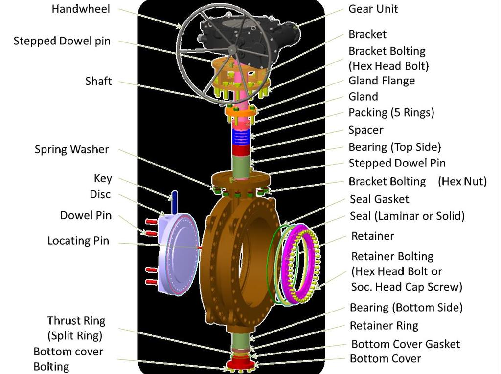
5 5

6 Delivery Valves are shipped with the disc closed condition. Orientation of the valve may be either horizontal or vertical depending on the shipped valve dimensions. Please check the packing slip attached to the container before opening the same. The valves and accessories shall be examined for any damages that might have happened during transportation and handling. Valve identification details can be found on the name plate and on the body of the valve. A typical identification plate is shown in Fig 2. Fig.1. Identification plate Valves are supplied with end protectors for avoiding damage to internals. Hand wheels for gear operated valves are usually dismantled and packed separately. Note: Refer Appendix B for valves with CE & ATEX certification requirements. 6
7 Handling and Storage Handling Valve shall be properly supported and secured before moving, to prevent possible damage to valve, property or harm to personnel. Do not drag the valve on the ground while transporting. A minimum of one foot height from the ground is to be maintained while moving the valve. Valve shall not be slung around the valve port for transportation. The crane wire should not be slung around the actuator/gear unit to avoid any load acting on it. Also, ensure that while handling the valve, no external load acts on the actuator/gear unit. Valves shall not be handled with the hand wheel keyed/ fixed to the gear unit. The hand wheel shall be dismantled before handling and transporting the valve. Storage Valves shall be stored in covered area which is dust free, least humid and well ventilated. Ensure that the end protectors are in place before the valve is stored, as dry contaminants like dust, sand, grit etc. can scratch metal seating surfaces and the soft parts, leading to leakage during operation. If the valve end protectors are opened for any check or testing, the same preservation and protection shall be done after the check or testing. The valve shall always be maintained in an ambience with temperature higher than the dew point temperature at the storage location, so as to avoid collection of water droplets on the valve surface. Do not keep the valve directly on the floor. Valve shall be placed on wooden pallet such that it is at least at a height of 6 inch from the floor. Care shall be exercised not to damage the extended portion of the adaptor, gear unit/ actuator while storage. Do not apply tar, grease or any other material inside the valve, as it could impair the performance of the valve. Improper storage and /or handling may cause disc/seal damage or deformation of shaft or seat, which will affect sealing and operational performance of the valve. 7
8 Planning & Responsibilities When installing or maintaining valves Conduct a risk assessment and eliminate or reduce hazards to an acceptable level. Work in accordance with safe systems of work site. Observe all site health and safety rules. Wear all necessary personal protective equipment. Never use a valve on a duty which exceeds its prescribed operating parameters. Refer to L&T Valves for further information The valve shall not be subjected to frequently occurring disturbances End user to ensure there are no external disturbances (e.g. Shocks, vibrations, electromagnetic fields etc.) Misuse of valves / valve components are strictly prohibited. Maximum surface temperature of the equipment will be same as the line media temperature. The end user must take account of the line media temperature. If the processes or environments that the valves are used in are likely to cause temperatures (high or low) that may cause injury to personnel if touched, then adequate insulation / protection must be fitted. Adequate safety measures shall be made for valves similar to pipe lines. Due to variety of duties in which these valves can be employed, it is the end user s responsibility to ensure the compatibility of media with the material of construction of the product for each specific application (i.e. corrosion and erosion which may affect integrity of the pressure containing envelope). Before valves are installed in areas which may be subject to seismic activity or extreme climatic conditions, consult L&T Valves with data. All exposed parts shall be cleaned to prevent dust deposit or insulation is needed similar to pipe line. Valves should be protected by other devices to prevent over-pressurisation. (i.e., caused by temperature, fire etc.). 8
9 Valve Installation General Carefully unpack the valve and check for tags or identification plates, etc. If the identification plate / arrow plate / tag is lost or destroyed during the shipment or while in storage or if it is not legible, contact your distributor or L&T Valves The performance of the valve will be better if the flow is smooth. It is suggested to avoid installation of valves where turbulence is expected (Example: Immediate after elbows, bends, pumps etc.) Look for any special warning tags or plate attached to or accompanying the valve and if any, take appropriate action. It is recommended to remove all foreign particles from the pipe line by flushing it with a suitable fluid. Corrosion inhibitors shall be added to the flushing medium to prevent any corrosion due to trapped fluids. Remove the end protectors and protective sheath within the flow bore valve, wherever provided. Gasket contact faces of the valve and pipe flanges shall be inspected thoroughly for scratches / defects. Scratches, if any, shall be corrected by grinding the surfaces or by rubbing with emery sheet. After cleaning, operate the valve for at least two complete cycles before installing. The pipes must be properly aligned and provisions made to minimize stresses from external load/thermal expansion. Always review pipe manufacturer s recommendation. In case of pipes with long overhangs, adequate support/jacks shall be provided at the flange ends of the pipe so as to avoid bending of pipes due to weight of the valve. For best performance it is recommended that these valves are installed with the shaft horizontal with the hand wheel facing up. Otherwise preferred to install shaft at an angle so that sediments cannot deposit on lower bearing area which affects the valve open, close operation. This valve has bi-directional sealing capabilities and therefore can be installed in either direction. However, a preferred flow direction is indicated in the valve by means of an arrow mark and it is strongly recommended that the valve is installed such that the flow is in the direction of the arrow. The improper alignment of the pipe and the valve during installation can lead to unbalanced tightening of the flanges which may cause excessive stress on the bolts and lead to leakage 9
10 Fig.2. Alignment of pipe and valve For wafer & wafer lug valves Check ZN dimension provided in the GAD & compare it with the pipe schedule used in the site. Fig.3. Installation of the valve 10
11 Flanged Ends Refer Appendix A1 for applicable standards Clean valve flanges and companion flanges and remove protective grease from the valve flanges. Clean the valve interiors adjacent piping priors to mounting of the valve pipe joint. Align the bolt holes of the valve end flange and pipe flange. Fasteners shall be lubricated for ease of installation Insert the gasket (not supplied with valve) and tighten the fasteners. Flange fasteners shall be tightened evenly. Using suitable device, in cross rotation to prevent damage to the flange. For sequence of tightening fasteners, refer Appendix A2 For larger flanged valves, which are provided with foot support supporting base/pedestal shall be placed beneath the valve after the alignment and bolting of the pipe. If valve is not cleaned or if cleaning is done after valve installation, cavities may form a natural trap in the piping system. Any impurity not dissolved or washed out by the flushing fluid/line fluid may settle in such cavities and adversely affect valve performance. Butt-welding Ends The valves provided with butt-welding ends preparation are as per standard ASME B16.25 or as per customer requirements. Please refer to the general assembly drawings for the exact buttwelding ends dimensions. The welding of valves onto the pipeline shall be performed by qualified welders using qualified procedures. Valves shall be kept in the closed position during welding. Care shall be taken to avoid weld spatter from falling onto the seating surfaces to prevent damage and maintain sealing effect between the metallic contacts. Local post weld heat treatment (PWHT) on the weld and heat affected zone (HAZ) shall be carried out if required by the procedure. It is recommended that the pipeline be flushed again after welding to avoid damage to disc and seat. The valve shall be kept fully open during flushing. After flushing is completed, operate the valve three times and ensure that it is smooth. It is recommended to carry out pressure testing of the joints. 11
12 Reorientation of Gear unit If reorientation of gear unit is required, follow the points below. Unscrew the Bracket/Gear unit boltings. Remove the Gear unit. Check the no of key ways in the Drive Bush, if 4 key ways are available in the Drive Bush, then rotate the Gear unit to the required orientation in the steps of 90, if two keyways are available, Remove the Gear unit, dismantle the drive bush from the top of the Gear unit & rotate it to the required orientation and assemble back to the Gear unit. Then mount the Gear unit to the valve. Tighten the bolts on Bracket/Gear unit. Operate the valve 2 or 3 times to check whether it was mounted correctly. For actuator reorientation, please check with factory for guideline. Re-orientation of Gear unit to be carried out only when there is no pressure in pipe line Fig.4. Gear unit orientation 12
13 Valve Operation General Operational life of the valve can be maximized if the valve is used within the rated range, in accordance with design parameters. For understanding the internal construction refer to the general assembly drawing of the valve. Operation Mechanism Quarter turn motion of the valve is achieved using Gear unit/hydraulic/pneumatic/ Electric Actuator. Gear Unit Gear units are provided on valves for easier operation. Usually clockwise operation is for closing and anti-clockwise for opening of the valve. The position of the valve can be noted using the position indicator provided on top of the gear unit. The number of turns will depend on the gear unit used. The gear units are self-locking type, i.e., the line fluid will not make the disc to rotate. The gear units have mechanical stopper screws for setting the exact open and close position which are factory set. Refer trouble shooting section for correcting the mechanical stoppers (if required). Forcing the hand wheel, Chain wheel or nut against the stops will not provide tighter shutoff of the valve and may damage the gear unit, only gear unit stopper adjustment will affect the valve shut off. Electric Actuator It gives multi-turn output and is fitted on the gear unit or the quarter turn electrical actuators are directly mounted on the valve. The multi turn actuator drives the gear unit which in turn rotates the shaft. Electrically actuated valves are provided with declutching mechanism for manual operation of the valve. For electric actuators, L&T Valves recommends to strictly adhere to the instructions as per actuator s manual. Electrically actuated butterfly valves are powered with gear unit, which convert multiple motor input turns into ¼ turn valve operation. The travel of the valve disc is limited by limit switches in the actuator housing and physical stop in the gear unit housing. Valve shutoff is affected by limit switch and physical stop settings. Improperly set limit switches and/or physical stops may damage the motor and/or gear unit. Pneumatic / Hydraulic /Electro-Hydraulic Pneumatic/hydraulic/Electro-Hydraulic actuators are fitted directly on the valve, without separate gear unit, as these actuators have built-in quarter turn mechanisms / special lever arrangement. It is recommended to strictly adhere to the instructions as per actuator manufacturer s manual. In case, valves are supplied as bare stem, as per customer requirement, ensure that connecting devices for actuators does not exert any axial or radial loads on the valve shaft, as it may lead to bending of the shaft and excessive loading on the disc. This in turn can cause the torque to increase and may lead to problem in valve operation 13
14 Do s and Don ts Do s Don ts Before taking valve for erection, make sure that is cleaned properly from inside and outside and there are no foreign particles or metallic chips sticking on to sealing element DO NOT install a valve in the pipe line without the operating mechanism While installing the operating mechanism make sure that the TOBV valves in fully closed position DO NOT attempt forcible assembly of actuator on to the valve shaft, In case of any difficulty in proper matching of the key-ways, refer to the detailed instructional manual Make sure to remove the entire rust preventive on the machined surface in the flow area before a valve is put in the pipe line. DO NOT hammer actuator surface to drive it in Carefully read the identification plate details and install the valve in the right place and for the correct duty conditions for which it is designed and manufactured. Butterfly valves have preferred sealing direction marked by an arrow on the valve body beneath the identification plate DO NOT use adaptor, actuator body and gear box casting as lifting points Make sure to supply rated voltage and frequency to the electrical actuator. DO NOT operate electrically operated valves from fully open or fully closed position for initial starting. Make sure to bring them to mid-travel position by hand operation and check phase for reversal, if any, correct the phase reversal immediately. Note that none of the safety devices like limit switch, torque switch etc., will be effective in case of wrong phase connecting to the actuator Refer the general assembly drawing for recommended valve installation. Valves should be installed in the line after visually checking the condition of disc seal, In case there is any damage to the disc seal, the valve will not be leak tight, in such a case, replace the seal, before installing the valve in the line. DO NOT use force multiplying devices like levers or pulleys. In case a valve demands excessive operating torque, make sure there is no artificial obstruction in the pipe line or in the operating mechanism TOBV valve needs care and maintenance in its use. Always make routine checks once in three months for the working condition of operating mechanism DO NOT remove operating mechanism from the valve when the disc is partially open/close. Always use recommended spares as per our guidance. Lined Pipes and Heavy walled pipes should have a minimum inside diameter well clear of Dimension "Zn" (Refer Figure) in Disc full open position Do not remove gland & gland packing while fluid pressure is in the line. These valves are not to be used for End of line service. 14

15 Maintenance Introduction For enhanced life of the valve and better operability, it is recommended to do a periodic inspection and maintenance of the valves as per the procedure explained below: The frequency of observation depends on its application. L&T Valves recommends that valve shall be inspected every 50 cycles or three months (whichever earlier) for smooth operation and leak free performance. This is recommended even for stored valves also. It is advisable to maintain a record of the performance of the valve. Safety Procedure Always depressurize the pipeline when taking up any maintenance activity on the valve/ actuator. Always disconnect the electrical supply to the electrical actuator before carrying out any maintenance activity on the valve/actuator. Study carefully and understand the instructions outlined in the installation, operation & maintenance manual of the valve & actuator before taking up any maintenance. In-line Maintenance 1.1 These butterfly valves require only minimum in-line maintenance for satisfactory performance. 1.2 Check Gland nuts for tightness at regular intervals. If loose, tighten them evenly. 1.3 Refer Table II for Gland nut tightening Torque. 15
16 Routine Maintenance 1. Gland Leak Check the tightness of the gland nuts and tighten evenly if required. If the leak persists, the packing may be renewed. 2. Packing Replacement Caution: DO NOT replace the gland packing when the line is under pressure. Do not overtighten packing and gland nuts. Over-tightening will increase the torque required to operate the valve. Remove the gear unit/actuator and connecting keys. Its position relative to the valve must be noted for reassembly of gear unit/actuator. Remove gland nut, gland flange and gland. Remove packing and carefully clean packing cavity and shaft. Insert new packing rings. Most of the packing rings are already cut so that they can be inserted around the stem. In case of solid moulded packing like Graphite rings, use a sharp knife and cut the ring at 30 angle. Then slightly twist the ring and insert it around the stem. Do not open up the ring as it could break. Reassemble gland, gland flange and gland nut. Reassemble connecting keys, gear unit/actuator and close the valve. Caution: The gear unit/actuator will be a free moving fit. Do not force it on the stem. Tighten the gland nuts and cycle the valve.pressurize the line. If leakage is detected, tighten the gland nuts slowly and evenly until leakage stops. 3. Gear Units Gear Operated valves are fitted with enclosed water tight worm gear units. The gears are designed to function without maintenance for many years. All gear units are lubricated with heavy bearing grease when assembled and may be refilled as required. Fig.5. Worm Gear unit 16
17 4. Actuators For maintenance of electrical /pneumatic/hydraulic actuator refer the instruction manual of the electric actuator Note: After maintenance of the TOBV, and before commissioning the same, please observe all the installation guidelines as mentioned in Valve Installation section. Periodic Maintenance Dismantling The pipeline shall be drained of the line fluid and the valve removed from the line before dismantling. Care should be taken during the removal of wafer and wafer lugged valves fitted with fail-open actuators. Such valves shall be closed using the manual over-ride gear unit before removing from the pipeline. If no manual over-ride is available, the fail open actuator shall be dismantled before the valve is removed from the pipe line. Subsequently, the valve shall be closed with a wrench and then removed. The Operator may be changed without removing the valve from the pipeline, however, the line pressure should be relieved. Maintenance of the operator shall be done as per manufacturer instruction. Operator shall be changed when the valve shall be in the fully closed condition. If the operator has a fail-safe position that cannot be overridden then unscrewing the bolting on the valve bracket should dismantle the actuator. 17
18 Dismantling and Assembly Procedure Dismantling Procedure Depressurize the line and open the valve to drain the line Valves shall be slung properly and supported before loosening companion flange bolts. Place the valve in platform or base and transport to the repair shop. Refer GA drawings / Exploded view for component identification Open the valve completely and loosen the bolts of gear unit. If Motor operated valve, remove the actuator prior to loosening of gear unit Remove & Rotate the gear unit 90 anti clockwise. Rotate the disc to 180 degrees position, such that the retainer side is opposite to body seat side. Loose the gland bolting s. Remove the Retainer screw, Retainer and Seal from the disc. Pull out the dowel pin from the disc hub side using puller. Remove the gear unit from valve. Remove Bracket, Gland, Gland flange, spacer & packing. Loose the bottom cover screws to remove bottom cover from the body. Hold the disc firmly by using tapped holes provided in the disc hub. Pull out the shaft from bottom side. Remove the disc from the body. Remove the bearings & bearing seal from the body. Carry out the required replacement of the parts and reassemble the valve with new parts 18
19 Assembly Procedure Follow our standard assembly procedure LTV-DEP-526. Below given is general instruction for assembly. Check for cleanliness of all components i.e. body, disc, Shaft, bearing etc. Insert the bearings & bearing seal. Apply Molykote 321R on the bearing seal. Place the body in horizontal position. Place the disc on the body. Insert the shaft with thrust plate from bottom side Place the key in the shaft and fix the key to disc hub. Insert the spacer, packing, gland in the stuffing box area and fix the gland flange by bolting. (Refer packing replacement section) Assemble the bracket and gear unit. Insert the dowel pin in the disc hub side to connect with shaft. Rotate the disc 180 degrees (such that the disc seal groove shall be opposite to the seat end) and insert the disc seal gasket in the groove, place the seal & bolt the retainer to the disc. Tighten the gear unit with the top flange of bracket. For necessary tightening torque values refer Table 1 & 2. 19
20 Troubleshooting Problem Reason Action Valve not fully closed Check the indicator position in the gear unit & Rotate the handwheel until the close position is reached. Adjust the close position mechanical stopper by quarter turn & then close the valve. Leaks across Disc Valve seating damaged Dismantle and replace seal Seal gasket worn out Dismantle and replace Gasket Packing loosened Tighten Gland nuts Leaks through Gland Packing worn out Replace packing Not closing fully Accumulation of debris on seat Flush the pipeline with the valve in fully open condition Leakage through Bottom cover Gasket worn out Dismantle and replace gasket Leakage thru End flange Gasket worn out Dismantle and replace gasket Noise/Vibration while opening & closing Over tightened gland bolting Loose and tighten the gland bolting with appropriate torque values for tightening IMPORTANT: All these procedures require emptying the upstream and downstream piping and removal of valve from the pipe line. If the piping system provides access to retainer ring side of the valve (e.g. by dismantling / expansion joint/man hole access), removal of valve from piping is not necessary. 20
21 Appendix A A1 - References Face to Face Dimensions API 609 ISO 5752 End Connections Butterfly Valves: Double flanged. Lug and Wafer type Metal valves for use in flanged pipe systems - Face to Face and Centre to Face dimensions ASME B16.5 Pipe Flanges and Flange Fittings (NPS ½ through NPS 24) ASME B16.47 Large Diameter Steel Flanges (NPS 26 through NPS 60) ASME B16.25 Butt Welding Ends Testing Standard API 598 Valve Inspections and Testing 21
22 A2 - Tightening Sequence & Torque The tightening sequence for all possible number of bolting is beyond the scope of this manual. However, the logic to be followed is explained below Tighten the first four nuts in the sequence shown Fig.6. This helps in correct location of the mating parts. Tighten the other bolts in the sequence shown Fig.7 the same way. The sequence goes clockwise around the bolt Ensure that the recommended torque (refer Table1&2) is maintained in all bolting. Fig. 6 Initial Tightening Fig. 7 Sequence of Tightening Table 1 Tightening Torque values for Carbon steel bolting Thread size Torque (+/-10%) (Nm) M8 16 M10 32 M12 57 M M M M M M M
23 Table 2 Tightening Torque values for Stainless steel bolting Thread size Torque (+/-10%) (Nm) M8 8 M10 15 M12 26 M16 65 M M

24 APPENDIX B For valves with CE & ATEX certification requirements Each valve has a stainless steel name plate fixed to the body. The nameplate is marked with details of "Catalogue number", along with various other details such as the materials of construction, Limiting temperatures, pressure rating as shown below According to PED 97/23/EC Fig.8. CE Marking Name Plate Definition of name plate marking above : Fig.9. ATEX Name Plate II = Equipment group 2 = Equipment category G = Gas zone suitability (Zones 1 & 2) D = Dust zone suitability (Zones 21 & 22) c = Type of protection (i.e.) constructional safety (EN ) X = Special conditions (EN ). Special Condition: X Surface temperature: As per EN :2001(E) paragraph 14.2.g, the temperature class or maximum surface temperature cannot be marked on the product as it is dependent on the operating conditions. However the maximum allowable operating temperature for the product is marked on the nameplate. Material tractability markings are hard marked on the valve body 24
. The equipment shall not be subjected to frequently occurring disturbances. End user to ensure there is no external disturbances (e.g. Shocks, vibrations, electromagnetic fields etc.")
25 CAUTIONARY NOTES When installing or maintaining valves Observation shall be made for safety codes and working practices relevant to gas zones 1 & 2 and dust zones 21 & 22 (as defined in EN :1998). The equipment shall not be subjected to frequently occurring disturbances. End user to ensure there is no external disturbances (e.g. Shocks, vibrations, electromagnetic fields etc.) Misuse of valves / valve components are strictly prohibited. If the processes or environments that the products are used in are likely to cause temperatures (high or low) that may cause injury to personnel if touched, then adequate insulation / protection must be fitted. Adequate safety measures shall be made for valves similar to pipe lines. Before equipment is installed in areas which may be subject to seismic activity or extreme climatic conditions consult L&T Valves with data. Maximum surface temperature of the equipment will be same as the line media temperature. The end user must take account of the line media temperature. All exposed parts shall be cleaned to prevent dust deposit or insulation is needed similar to pipe line. This equipment should be protected by other devices to prevent over-pressurization. (i.e. caused by external fire etc.). End user to ensure that the accessories (actuator, limit switches, solenoid valve, etc.) if fitted with valve are of ATEX qualified as per the directive. Valves are not suitable for terminal connections. In such cases, valves shall be fitted with blind flanges. 25
26 Document No : LTV-528-R2/0314 As we continuously endeavor to improve our products, the data given herein is subject to change. Please refer for the latest IOM 26
Installation, Operation and Maintenance Manual of Forged Steel Gate, Globe & Check Valves
 Installation, Operation and Maintenance Manual of Forged Steel Gate, Globe & Check Valves Contents Page L&T Valves 3 Forged steel Gate, Globe & Check Valves 4, 5 Exploded Views 6, 7, 8, 9, 10 Shipment
Installation, Operation and Maintenance Manual of Pressure Seal Gate, Globe & Check Valves
 Installation, Operation and Maintenance Manual of Pressure Seal Gate, Globe & Check Valves Contents Page No. L&T Valves 3 Pressure Seal Gate, Globe & Check Valves 4, 5 Exploded View 6, 7, 8, 9 Delivery
Installation, Operation and Maintenance Manual of Pressure Seal Gate, Globe & Check Valves
 Installation, Operation and Maintenance Manual of Pressure Seal Gate, Globe & Check Valves Contents Page L&T Valves 3 Pressure Seal Bonnet Valves 4 Exploded Views 6 Delivery 12 Handling and Storage 13
When installing the screwed end, socket weld & flanged end valves the following respective procedures shall be followed for better performance.
 1. Storage LARSEN & TOUBRO LIMITED Page 1 of 5 1.1. All valves are to be stored in fully open position, in order to protect the sphere surface and soft valve seats. 1.2. Before shipping, the inlet and
Installation, Operation and Maintenance Manual for AlL Pressure seal Bonnet/Cover Class 600, 900, 1500 & 2500 Cast steel Gate, Globe & Check Valves
 Installation, Operation and Maintenance Manual for AlL Pressure seal Bonnet/Cover Class 600, 900, 1500 & 2500 Cast steel Gate, Globe & Check Valves AUDCO INDIA LIMITED Chennai India AIL REF. No: IOM/PS/001
GT-200 GATE VALVES PN16, Screwed end
 Document No. : MD-QO-04-281 Date : 2009/07 /17 Version : 1.0 GT-200 GATE VALVES PN16, Screwed end USER MANUAL Modentic Industrial Corporation 14F-1,No.57Taya Rd.,Taichung,Taiwan,R.O.C. Email:modentic@ms9.hinet.net
KEYSTONE SERIES 320 BUTTERFLY VALVES INSTALLATION AND MAINTENANCE INSTRUCTIONS
 Before installation these instructions must be fully read and understood HAZARD POTENTIALS disregarding of instructions improper use of product insufficiently qualified personnel Valve application to be
KEYSTONE. Butterfly valves Figure 9 Installation & Maintenance Instructions. Please read these instructions carefully
 KEYSTONE Please read these instructions carefully This symbol indicates important messages and safety instructions. Hazard potentials: disregarding of instructions improper use of product insufficiently
Triple-offset Butterfly Valves
 Triple-offset Butterfly Valves ASME Class 150 to 1500 3 to 100 (80 mm to 2500 mm) API 609 L&T Valves L&T Valves is a wholly owned subsidiary of Larsen & Toubro. Backed by a heritage of excellence that
Keystone Series GR resilient seated butterfly valves GRW/GRL Installation and operation manual
 Before installation these instructions must be fully read and understood Important Before valves are installed or used the following actions are recommended. 1. Valves/parts have to be inspected and thoroughly
INSTALLATION, OPERATION, MAINTENANCE MANUAL FOR MANUALLY OPERATED STOP CHECK VALVE
 INSTALLATION, OPERATION, MAINTENANCE MANUAL FOR MANUALLY OPERATED STOP CHECK VALVE Page 1 of 13 1.1 General CHAPTER 1 - GENERAL INFORMATION This manual contains maintenance instructions with pertinent
Butterfly valves Figure 56 Installation & Maintenance Instructions
 KEYSTONE Please read these instructions carefully This symbol indicates important messages and safety instructions. Hazard potentials: disregarding of instructions improper use of product insufficiently
Installation, Operation, and Maintenance Manual Full Port Y-Pattern, Bolted Bonnet, Globe and Check Valves
 SMITH VALVES Installation, Operation, and Maintenance Manual Full Port Y-Pattern, Bolted Bonnet, Globe and Check Valves Globe Valve Series: YG80/YG15 Welded Bonnet Globe Valve Series: YG87/YG17 Piston
Danfoss Butterfly Valve
 Triple Eccentric Danfoss Butterfly Valve Operating, installation and maintenance instructions Edition 1 / January 2015. Table of Contents: 1 Overview... - 1-2 General... - 1-2.1 Safety notes... - 1-2.2
Keystone Butterfly valves ParaSeal Installation and maintenance instructions
 Before installation these instructions must be fully read and understood Please read these instructions carefully Hazard potentials: disregarding of instructions improper use of product insufficiently
IOM Manual. IOM Manual. Series 76/77.
 IOM Manual IOM Manual Series 76/77 www.flowlinevalves.com Flow Line Valve and Controls, L.L.C. 110 Main Project Road Schriever, LA 70395 P.O. Box 677 Schriever, LA 70395 Phone 985-414-6004 * Toll Free
CompoSeal butterfly valves, wafer style Installation & Maintenance Instructions
 Please read these instructions carefully This symbol indicates important messages and safety instructions. Intended valve use The valve is intended to be used only in applications within the pressure/temperature
LNG Screw Down Non-Return Valve Installation, Operation and Maintenance Manual
 Installation, Operation and Maintenance Manual Date of Issue: 04 August 2010 Page 1 of 27 QF 80: Issue 2 WARNING! BEFORE ANY INSTALLATION AND MAINTENANCE WORK CAN COMMENCE ENSURE THE VALVE AND SURROUNDING
Newco / OIC / Cooper Forged Valves. Operation & Maintenance. Manual
 NEWCO / OIC / COOPER VALVES Newmans Inc., Newmans Valve Ltd. Operation & Maintenance Manual Revision 2, 9 May 2007 1. Introduction and Safety Information... 1 1.1. Introduction... 1 1.2. Safety Information...
Triple-offset Butterfly Valves
 Triple-offset Butterfly Valves ASME Class 150 to 1500 3 to 100 (80 mm to 2500 mm) API 609 L&T Valves Triple-offset Butterfly Valves L&T Valves is a wholly owned subsidiary of Larsen & Toubro. Backed by
Double Block & Bleed Plug Valves
 Double Block & Bleed Plug Valves ASME Class 150 & 300 50 mm to 750 mm (2 to 30 ) API 6D L&T Valves L&T Valves Limited (Formerly Audco India Limited) is a wholly owned subsidiary of Larsen & Toubro. Backed
MK Series - High Performance Butterfly Valves Operation and Maintenance Instructions
 COMMERCIAL Bray Controls Commercial Division 13788 West Road, Suite 200A Houston, Texas 77041 BCDSales@Bray.com Phone: 1-888-412-2729 Fax: 1-888-412-2720 www.braycommercialdivision.com MK Series - High
DOUBLE OFFSET BUTTERFLY VALVE
 Flange STD: ASME CLASS 150 LB ASME CLASS 300 LB Temp :210 ~29 Work pressure: VF-91_/92_/93_ 2 ~48 150LB VF-94_/95_/96_ 2 ~24 300LB Pd. date 2011.5 Please read all of these instructions before installing
COMMERCIAL. BV & BVM Series Installation Instructions 06/29/15
 COMMERCIAL Bray Controls Commercial Division 13788 West Road, Suite 00A Houston, Texas 77041 BCDSales@Bray.com Phone: 1-888-41-79 Fax: 1-888-41-70 www.braycommercialdivision.com BV & BVM Series Installation
Operating Guide SBFV (PN16/25) ENGLISH Steel butterfly valve SBFV Page 2. Danfoss VI.IX.A1.02 1
 ENGLISH Steel butterfly valve SBFV Page 2. Danfoss VI.IX.A1.02 1") Operating Guide SBFV (PN16/25) ENGLISH Steel butterfly valve SBFV www.danfoss.com Page 2 Danfoss 2016.06 VI.IX.A1.02 1 Table of Contents: 1. OVERVIEW... 3 2. GENERAL... 3 2.1 Safety...3 2.2 Proper use...4
Operating Guide SBFV (PN16/25) ENGLISH Steel butterfly valve SBFV www.danfoss.com Page 2 Danfoss 2016.06 VI.IX.A1.02 1 Table of Contents: 1. OVERVIEW... 3 2. GENERAL... 3 2.1 Safety...3 2.2 Proper use...4
5000/6000 SERIES BALL VALVES INSTALLATION - MAINTENANCE MANUAL
 Date: August 2011 / Page 1 of 6 5000/6000 SERIES BALL VALVES INSTALLATION - MAINTENANCE MANUAL DESIGN The design features three piece construction and a free floating ball allowing ease of maintenance
Installation, Operation and Maintenance Manual for the HE Series
 Installation, Operation and Maintenance Manual for the HE Series High Performance Butterfly Valve "Double Offset" CONTENT IOM-HP-100614-1 1. INTRODUCTION 1.1 GENERAL NOTE 1.2 STRUCTURE & TYPE 1.3 OPERATION
Ver Trunnion Ball Valve INSTALLATION, OPERATION AND MAINTENANCE MANUAL FBV/IOM/BA02
 Ver. 2008 Trunnion Ball Valve INSTALLATION, OPERATION AND MAINTENANCE MANUAL FBV/IOM/BA02 TABLE OF CONTENTS 1 APPLICATIONS...2 1.1 Applications...2 1.2 Performance Specifications...2 2 APPLICABLE STANDARDS...2
Bolted Bonnet Gate Valves. Installation, Operation & Maintenance Manual
 Installation, Operation & Maintenance Manual Bolted Bonnet Gate Valves L&T Valves Valve Manufacturing Unit Larsen & Toubro Limited L&T Campus, Malumichampatti Coimbatore 641050 Tamil Nadu India Table of
Aquaseal Butterfly & Check Valves
 Aquaseal Butterfly & Check Valves L&T Valves L&T Valves Limited (formerly Audco India Limited) is a wholly-owned subsidiary of L&T and one of the largest valve manufacturers in the world. The company has
FRP Ball Valves INSTALLATION & MAINTENANCE MANUAL
 FRP Ball Valves INSTALLATION & MAINTENANCE MANUAL FRP BALL VALVES TABLE OF CONTENTS MAINTENANCE AND INSTALLATION INSTRUCTIONS 1. 2. 2.1 2.2 2.3 2.4 GENERAL...Page 1 HANDLING...1 Receiving and Storing...1
Double Offset High Performance Butterfly Valve
 Double Offset High Performance Butterfly Valve INSTALLATION OPERATION MAINTENANCE APOLLO INTERNATIONAL HIGH PERFORMANCE BFV IOM - Page 2 of 20 TABLE OF CONTENTS INTRODUCTION 3 PRODUCT STORAGE 3 PRODUCT
Ball Valves. ASME Class 150 to mm mm (¼" - 8") ISO 17292/ API 6D
 ISO 17292/ API 6D") Ball Valves SM Class 150 to 2500 8 mm - 200 mm (¼" - 8") ISO 17292/ PI 6D L&T Valves Limited is a wholly owned subsidiary of Larsen & Toubro. Backed by a fifty-year track-record of excellence and world-leading
Ball Valves SM Class 150 to 2500 8 mm - 200 mm (¼" - 8") ISO 17292/ PI 6D L&T Valves Limited is a wholly owned subsidiary of Larsen & Toubro. Backed by a fifty-year track-record of excellence and world-leading
Instalation, Operation and Maintenance Manual
 POWER BALL VALVE Instalation, Operation and Maintenance Manual Rev. 1 1 of 23 INDEX PAGE 1.0 INTRODUCTION-----------------------------------------------------------------------------4 2.0 RECEIVING & PREPARATION
KEYSTONE OPTISEAL F14/16-15/17 AND BREWSEAL BUTTERFLY VALVES INSTALLATION AND MAINTENANCE INSTRUCTIONS
 Before installation these instructions must be fully read and understood 4. Ozone: storage rooms should not contain any equipment generating ozone. E.g. lamps, electric motors. IMPORTANT Before valves
MERIDIAN, 2 or 3 PIECE, TRUNNION MOUNTED BALL VALVES
 INSTALLATION, OPERATION AND MAINTENANCE INSTRUCTIONS MERIDIAN, 2 or 3 PIECE, TRUNNION MOUNTED BALL VALVES Size Range 2 48 ASME Classes 150-2500 *It is recommended that the valve installer is familiar with
Installation, Operation and Maintenance Guide II NIBCO High Performance Butterfly Valves Series 6822 and 7822
 Installation, Operation and Maintenance Guide II NIBCO High Performance Butterfly Valves Series 6822 and 7822 Statements: NIBCO High Performance Butterfly Valves, Series 6822 and 7822, have been designed
Aquaseal Butterfly & Check Valves
 Aquaseal Butterfly & Check Valves L&T Valves L&T Valves Limited (formerly Audco India Limited) is a wholly-owned subsidiary of L&T and one of the largest valve manufacturers in the world. The company has
Double Block and Bleed Plug Valves
 Double Block and Bleed Plug Valves ASME Class 150 to 600 50 mm to 1050 mm (2 to 42 ) API 6D L&T Valves L&T Valves is a wholly owned subsidiary of Larsen & Toubro. Backed by a heritage of excellence that
IMOI 2010 Rev 0
 FOREWORD The following instructions are offered as a reference aid to the valve user when installing, maintaining or operating Williams Gate, Globe and Swing Check valves. This document, consisting of
Installation, Operation, and Maintenance Manual. Gate, Globe, and Check Valves
 SMITH VALVES Installation, Operation, and Maintenance Manual Gate, Globe, and Check Valves TNC Doc EDC 303, Revision 7, Issued November 2013 TABLE OF CONTENTS 1.0 - GENERAL 2.0 - INSTALLATION 3.0 - OPERATION
Rating Integrally-moulded Butterfly Valve - Class 150. Rating
 L&T Valves L&T Valves Limited is a wholly-owned subsidiary of L&T and one of the largest valve manufacturers in the world. The company has three modern manufacturing facilities, in Chennai, Coimbatore
Mounting and Operating Instructions EB 8135/8136 EN. Series V2001 Valves Type 3535 Three-way Valve for Heat Transfer Oil
 Series V2001 Valves Type 3535 Three-way Valve for Heat Transfer Oil Type 3535 Three-way Valve with bellows seal and rod-type yoke (partial view) Mounting and Operating Instructions EB 8135/8136 EN Edition
Ideal Installation. I & M Mark 67 (1/2 6 ) Control Line. Installation & Maintenance Instructions for Mark 67 Pressure Regulators
 Control Line. Installation & Maintenance Instructions for Mark 67 Pressure Regulators") I & M Mark (/ ) 0 Wasson Road Cincinnati, OH 0 USA Phone --00 Fax -8-00 info@richardsind.com www.jordanvalve.com Installation & Maintenance Instructions for Mark Pressure Regulators Warning: Jordan Valve
I & M Mark (/ ) 0 Wasson Road Cincinnati, OH 0 USA Phone --00 Fax -8-00 info@richardsind.com www.jordanvalve.com Installation & Maintenance Instructions for Mark Pressure Regulators Warning: Jordan Valve
Apollo Standard Port, Full Port & One Piece Flanged Ball Valves Installation, Operation, & Maintenance Guide
 I854000.F M16005 Apollo Standard Port, Full Port & One Piece Flanged Ball Valves Introduction This manual presents guidelines for the Installation, Operation and Maintenance of manual and automated Apollo
DeZURIK " BAW AWWA BUTTERFLY VALVES WITH EPOXY-RETAINED SEAT
 DeZURIK 20 144" BAW AWWA BUTTERFLY VALVES WITH EPOXY-RETAINED SEAT Instruction D10373 April 2017 Instructions These instructions provide information about the 20 (250 F2 model only) and the 24-144 BAW
Scope. Applicability. Caution. I & M CV3000 Series. Storage. Installation & Maintenance Instructions for Marwin CV3000 Series Three Piece Ball Valves
 I & M CV3000 Series 3170 Wasson Road Cincinnati, OH 45209 USA Phone 513-533-5600 Fax 513-871-0105 marwin@richardsind.com www.marwinvalve.com Installation & Maintenance Instructions for Marwin CV3000 Series
Operating & Maintenance Manual For Steam Conditioning Valve
 For Steam Conditioning Valve 1 Table of Contents 1.0 Introduction 3 2.0 Product description 3 3.0 Safety Instruction 4 4.0 Installation and Commissioning 5 5.0 Valve Disassembly 6 6.0 Maintenance 6 7.0
IMO-200EN 09/2010. Trunnion mounted forged ball valves Model FF and GG. Installation, Maintenance and Operating Instructions IMO-200EN 09/2010
 IMO-200EN 09/2010 Trunnion mounted forged ball valves Model FF and GG Installation, Maintenance and Operating Instructions IMO-200EN 09/2010 2 IMO-200EN Table of Contents I GENERAL INFORMATION...................
Val-Matic QuadroSphere Trunnion Mounted Ball Valve
 Manual No. QS-OM1-1 Val-Matic QuadroSphere Trunnion Mounted Ball Valve Operation, Maintenance and Installation Manual INTRODUCTION... 2 RECEIVING AND STORAGE... 2 INSTALLATION... 2 DESCRIPTION OF OPERATION...
USER INSTRUCTIONS. Serck Audco Slimseal Wafer-Type Butterfly Valves. Installation Operation Maintenance. Experience In Motion SREEIM /13
 USER INSTRUCTIONS Serck Audco Slimseal Wafer-Type Butterfly Valves SREEIM0006-02 06/13 Installation Operation Maintenance Experience In Motion Contents Storage 4 Identification of Valves 4 Construction
Installation, Operation and Maintenance Manual
 Installation, Operation and Maintenance Manual for the irsvp Metal Seated Ball Valve ASME Class 1500 / 3100 / 4500 PREPARE THE VALVE FOR INSTALLATION INSTALL THE VALVE PROPERLY STRESS RELIEVE WELDS ACCORDING
INSTALLATION & MAINTENANCE MANUAL
 INSTALLATION & MAINTENANCE MANUAL 3-WAY/4-WAY/5-WAY MULTI-PORT BALL VALVES T TEFLON PARTS - 1. Seat x 5 pcs. 2. Joint Gasket x 5 pcs. 3. Retainer Seal x 5 pcs. 4. Thrust Washer x 1 pc. 5. O-Ring x 1 pc
KEYSTONE SERIES GRF RESILIENT SEATED BUTTERFLY VALVES INSTALLATION AND OPERATION MANUAL
 Before installation these instructions must be fully read and understood Intended valve use The valve is intended to be used only in applications within the pressure/temperature limits indicated in the
KEYSTONE Figure 990/991 Butterfly valves Installation, operation and maintenance instructions
 Before installation these instructions must be fully read and understood Potentially dangerous practices: disregarding instructions improper use of product use of insufficiently qualified personnel Application
Crispin Valves Operating Guide. Crispin
 Crispin Valves Operating Guide Crispin Since 1905 Crispin Multiplex Manufacturing Co. 600 Fowler Avenue Berwick, PA 18603 1-800-AIR-VALV T: (570) 752-4524 F: (570) 752-4962 www.crispinvalve.com sales@crispinvalve.com
Installation Operation Maintenance. LSSN Butterfly Valve AGA Approved 50MM - 150MM. QAD#IM6055.REVA
 LSSN Butterfly Valve Installation Operation Maintenance Licence Number: 5326 www.challengervalves.com.au 1 Index 1. INTRODUCTION 1.1 Design Features 3 1.2 Flange and Pipe Compatibility 4 1.3 Operating
BUTTERFLY VALVE WITH WELDED ENDS INSTALLATION AND MAINTENANCE MANUAL
 BUTTERFLY VALVE 31300 SERIES INSTRUCTIONS FOR INSTALLATION, USE AND MAINTENANCE 1. Overview Read these instructions carefully before starting the valve installation and start-up work. Safe keep the instructions
AIL METSEAL Butterfly Valves
 AIL METSEAL Butterfly s The AIL METSEAL Butterfly is a high performance valve which is used for positive isolation in Power Generation, Petroleum Refining, Oil and Gas Production, Chemical, Petrochemical
Mounting and Operating Instructions EB 8222 EN. Type 3310/AT and Type 3310/3278 Pneumatic Control Valves. Type 3310 Segmented Ball Valve
 Type 3310/AT and Type 3310/3278 Pneumatic Control Valves Type 3310 Segmented Ball Valve Fig. 1 Type 3310/3278 with positioner Fig. 2 Type 3310/AT Mounting and Operating Instructions EB 8222 EN Edition
Bolted Bonnet Check Valve. Installation, Operation & Maintenance Manual
 Installation, Operation & Maintenance Manual Bolted Bonnet Check Valve L&T Valves Limited L&T Campus, Malumichampatti Coimbatore 641021 Tamil Nadu India Table of Contents 1 Introduction 1.1 Scope 2 General
Keystone Figure 85/86 Check valves Installation and Maintenance Instructions
 Please read these instructions carefully 1.3 Handling 1.3.1 Packed valves Lifting and handling of the packed valves in crates should be carried out by appropriate lifting equipment. If a fork lift truck
PRESSURE REGULATOR BACK PRESSURE TO ATMOSPHERE WITH OUTSIDE SUPPLY
 PRESSURE REGULATOR BACK PRESSURE TO ATMOSPHERE WITH OUTSIDE SUPPLY All Rights Reserved. All contents of this publication including illustrations are believed to be reliable. And while efforts have been
INSTALLATION, OPERATION & MAINTENANCE MANUAL Description Handling Installation Actuators...
 INSTALLATION, OPERATION & MAINTENANCE MANUAL INDEX Page 0 - Description 2 1 - Handling 2 2 - Installation 2 3 - Actuators 5 4 - Maintenance 5 41 - Gland packing replacement 6 42 - Seal replacement 6 43
McCannalok HIGH PERFORMANCE BUTTERFLY VALVE OPERATION AND MAINTENANCE MANUAL. The High Performance Company
 McCannalok HIGH PERFORMANCE BUTTERFLY VALVE OPERATION AND MAINTENANCE MANUAL The High Performance Company Table of Contents Safety Information - Definition of Terms... 1 Introduction... 1 Installation...
Installation, Operation, and Maintenance Manual
 Industrial Process Installation, Operation, and Maintenance Manual Series PBV Plastic Lined Ball Valve Table of Contents Table of Contents Introduction and Safety...2 Safety message levels...2 User health
Butterfly Valve Type 57P
 Butterfly Valve Type 57P Contents Lever Type: 50-200 mm (2-8 ) Body Material: CPVC Gear Type: 50-200mm (2-8 ) Body Material: CPVC (1) Be sure to read the following warranty clauses of our product 1 (2)
2.- HANDLING OF VALVES BEFORE ASSEMBLY 3.- FITTING THE VALVE TO THE REST OF THE ASSEMBLY 5.- PERIODICAL INSPECTION OF THE VALVE AND MAINTENANCE
 Page 1 of 16 CONTENTS 1.- INTRODUCTION 2.- HANDLING OF VALVES BEFORE ASSEMBLY 3.- FITTING THE VALVE TO THE REST OF THE ASSEMBLY 4.- OPERATION OF A BALL VALVE 5.- PERIODICAL INSPECTION OF THE VALVE AND
Fisher TBX Hydro Plug Fixture
 Instruction Manual TBX Hydro-Plug Fixture Fisher TBX Hydro Plug Fixture Contents Introduction... 1 Scope of Manual... 1 Description... 2 Educational Services... 2 Principle of Operation... 2 Maintenance...
USER INSTRUCTIONS. Valtek Valdisk TX3 Triple Offset Butterfly Control Valve. Installation Operation Maintenance. Experience In Motion
 USER INSTRUCTIONS Valtek Valdisk TX3 Triple Offset Butterfly Control Valve Installation Operation Maintenance Experience In Motion Contents 1. General Information and Precautions 3 2. Unpacking 4 3. Installation
HIGH PRESSURE CONTROL VALVE PISTON BALANCED
 PISTON BALANCED All Rights Reserved. All contents of this publication including illustrations are believed to be reliable. And while efforts have been made to ensure their accuracy, they are not to be
TRITEC (TT2) Instruction Manual
 Instruction Manual") 1/9 TRITEC (TT2) Instruction Manual 1. Introduction P2 2. Features of Triple Offset Valve (Torque Sealing) P2 3. Standard Specifications P2 4. Handling Procedure 4.1 Packaging P3 4.2 Transportation Conditions
1/9 TRITEC (TT2) Instruction Manual 1. Introduction P2 2. Features of Triple Offset Valve (Torque Sealing) P2 3. Standard Specifications P2 4. Handling Procedure 4.1 Packaging P3 4.2 Transportation Conditions
Fisher CVX Hydro Plug Fixture
 Instruction Manual CVX Hydro-Plug Fixture Fisher CVX Hydro Plug Fixture Contents Introduction... 1 Scope of Manual... 1 Description... 1 Educational Services... 2 Principle of Operation... 2 Maintenance...
TBV OPERATION AND MAINTENANCE MANUAL SERIES 1800: FLANGED BALL VALVE. For technical questions, please contact the following:
 TBV OPERATION AND MAINTENANCE MANUAL SERIES 1800: FLANGED BALL VALVE For technical questions, please contact the following: Engineering Department 1537 Grafton Road Millbury, MA 01527 Phone: (508) 887-9400
Series A Floating Ball Valve Installation, Operation & Maintenance XXXX - X X X X X X X. Base Part Numbers. Trim Option Suffix Code
 Series A Floating Ball Valve Installation, Operation & Maintenance Base Part Numbers RATING 1 FP 2 RP 2 FP 3 RP 3 FP 4 RP 4 FP 1000 1102 1103 1104 1106 1105 1107 1500 1151 1152 1153 1154 1156 1155 1157
METERING VALVE 2" STEM GUIDED
 2" STEM GUIDED All Rights Reserved. All contents of this publication including illustrations are believed to be reliable. And while efforts have been made to ensure their accuracy, they are not to be construed
VSI INDUSTRIAL BALL VALVES SERIES 7100 SERIES 8100 SERIES 7200 SERIES 8300 SERIES 7400 SERIES 8400 SERIES 8000 SERIES 8500
 VSI INDUSTRIAL BALL BUTTERFLY VALVES VSI INDUSTRIAL BALL VALVES SERIES 7100 SERIES 8100 SERIES 7200 SERIES 8300 SERIES 7400 SERIES 8400 SERIES 8000 SERIES 8500 INSTALLATION, OPERATION AND MAINTENANCE MANUAL
CV Control Valves Installation and Operation Manual
 CV1500 - Control Valves Installation and Operation Manual 652-EN Overview Warning: This bulletin should be used by experienced personnel as a guide to the installation of the Armstrong CV1500 Control Valve.
VSI, LLC SERIES 2100 RESILIENT SEATED BUTTERFLY VALVES INSTALLATION, OPERATION AND MAINTENANCE MANUAL
 VSI SERIES 2100 RESILIENT SEATED BUTTERFLY VALVES VSI, LLC. 2-0 SERIES 2100 RESILIENT SEATED BUTTERFLY VALVES INSTALLATION, OPERATION AND MAINTENANCE MANUAL Publication: V2100- August 2016 TABLE OF CONTENTS
OPERATION AND MAINTENANCE INSTRUCTIONS
 OPERATION AND MAINTENANCE INSTRUCTIONS 334 SERIES THREE-PIECE BALL VALVES 1/4 to 2-1/2 Installation and Operation Always install your valve according to accepted industry standards and practices and operate
KEYSTONE. Check valves Figure 85/86 Installation & Maintenance Instructions. Figure 85. Figure 86.
 KEYSTONE Please read these instructions carefully. This symbol indicates important messages and safety instructions. Hazard potentials: disregarding of instructions improper use of product insufficiently
Power-Seal High Performance Butterfly Valve: Series P1 Installation & Maintenance Manual
 CAUTION: 1. For your safety read this manual completely before installation or servicing. 2. Before installing or servicing, please ensure the line pressure has been relieved, and any hazardous fluids
Mounting and Operating Instructions EB 8039 EN. Type 3351 Pneumatic On/off Valve. Type 3351 Pneumatic On/off Valve. Type 3351 Pneumatic On/off Valve
 Type 3351 Pneumatic On/off Valve Type 3351 Pneumatic On/off Valve Type 3351 Pneumatic On/off Valve Version with handwheel Mounting and Operating Instructions EB 8039 EN Edition May 2016 Definition of signal
OPERATION AND MAINTENANCE MANUAL 2-66 SERIES 2500 RESILIENT WEDGE GATE VALVE
 OPERATION AND MAINTENANCE MANUAL 2-66 SERIES 2500 RESILIENT WEDGE GATE VALVE INDEX SERIES 2500 DUCTILE IRON RESILIENT WEDGE GATE VALVE OPERATION and MAINTENANCE MANUAL. OPERATION AND MAINTENANCE Operation,
LOW PRESSURE BALANCED VALVE DIAPHRAGM BALANCED
 DIAPHRAGM BALANCED All Rights Reserved. All contents of this publication including illustrations are believed to be reliable. And while efforts have been made to ensure their accuracy, they are not to
Baumann Way Control Valve
 Instruction Manual 24003 Valve Baumann 24003 3-Way Control Valve Contents Introduction... 1 Scope of Manual... 1 Safety Precautions... 2 Educational Services... 3 Maintenance... 3 Installation... 3 Air
USER INSTRUCTIONS. Installation Operation Maintenance. NAF Setball SF Ball Sector Valves. Experience In Motion FCD NFENIM A4 09/16
 USER INSTRUCTIONS NAF Setball SF Ball Sector Valves FCD NFENIM4156-00 A4 09/16 Installation Operation Maintenance Experience In Motion Contents SAFETY 3 1 General 3 2 Lifting 4 3 Receiving Inspection 4
Installation Operation Maintenance
 Installation Operation Maintenance www.challengervalves.com.au 1 QAD#IM1015 REVC 3.10.15 Index 1. INTRODUCTION 3 1.1 Design Features 1.2 Flange and Pipe Compatibility 3 1.3 Operating Pressures and Temperatures
MEMORY SEAL BALL VALVES MAINTENANCE MANUAL 2 12, Class 150 & 300, Regular Port, Flanged Unibody
 MEMORY SEAL BALL VALVES MAINTENANCE MANUAL 2 12, Class 150 & 300, Regular Port, Flanged Unibody I INTRODUCTION These rugged, versatile, high performance, regular port, ball valves meet all requirements
Standard Valves Series Globe Valves Series Angle Valves Series Way-Valves
 Installation, Operation, Maintenance Instructions Standard Valves Series 035 000 Globe Valves Series 031 000 Angle Valves Series 033 000 3-Way-Valves 1 GENERAL INFORMATION These instructions are designed
Split Body Valves with Bellows Seal Series Globe Valves Series Angle Valves Series Way-Valves
 Installation, Operation, Maintenance Instructions Split Body Valves with Bellows Seal Series 025 300 Globe Valves Series 027 300 Angle Valves Series 028 300 3-Way-Valves 1 GENERAL INFORMATION These instructions
Bray/Mckannalok Butterfly Valve Series 40/41/42/43/44/45 Installation Manual Technical Bulletin No Date: May 2004/Page 1 of 6
 Date: May 2004/Page 1 of 6 Bray/McCannalok Butterfly Valves Installation and Maintenance Instructions ANSI Classes 150 and 300 - Sizes 2-1/2 through 24 ANSI Classes 600 - Sizes 3 through 16 Bidirectional
Installation, Operation And Maintenance Manual. Manual. For the 400 Series. ABZolute Seal. High Performance Butterfly Valve "Double Offset"
 Installation, Operation And Maintenance Manual Manual For the 400 Series ABZolute Seal High Performance Butterfly Valve "Double Offset" ABZ VALVE & CONTROLS CONTENT 1. INTRODUCTION 1.1 GENERAL NOTE 1.2
Mounting and Operating Instructions EB 8111/8112 EN. Series V2001 Valves Type 3321 Globe Valve
 Series V2001 Valves Type 3321 Globe Valve Type 3321 Globe Valve with rod-type yoke and Type 3372 Electropneumatic Actuator (350 cm²) Mounting and Operating Instructions EB 8111/8112 EN Edition June 2013
back to main page Type: Butterfly valves Instructions and Operation Manual Warning! Warning! Danger for life! 1. Intended use Danger for life!
 Instructions and operation manual for butterfly valves This manual is intended to support the users of Herberholz butterfly valves type HRD/HRA, RD/RA, LDKE/LDKF for installation, operation and maintenance
INSTALLATION, OPERATION & MAINTENANCE MANUAL. 0.- Description Handling Installation Actuators Maintenance...
 INSTALLATION, OPERATION & MAINTENANCE MANUAL INDEX Page 0- Description 2 1- Handling 2 2- Installation 2 3- Actuators 5 4- Maintenance 5 41- Gland packing replacement 5 42- Seal replacement 6 43- Gasket
2" - 24" OS Series Butterfly Valves. Operation and Maintenance Manual. Job Name: Contractor: Date:
 s Operation and Maintenance Manual Job Name: Contractor: Date: Document #: IOM Revision Date: 10/2/2016 SAFETY MESSAGES All safety messages in the instructions are flagged with an exclamation symbol and
V-SEGMENT SERIES V-Port Segment Control Valves (VS/VV/VM) Installation & Maintenance Manual
 Installation & Maintenance Manual") CAUTION: 1. For your safety read this manual before installation or servicing. 2. Before installing or servicing, please ensure the line pressure has been relieved, and any hazardous fluids have been drained
CAUTION: 1. For your safety read this manual before installation or servicing. 2. Before installing or servicing, please ensure the line pressure has been relieved, and any hazardous fluids have been drained
Fisher RSS Lined Globe Valve
 Instruction Manual D0990 RSS Valve July 07 Fisher RSS Lined Globe Valve Contents Introduction... Scope of Manual... Description... Educational Services... Specifications... Installation... Maintenance...
Mounting and Operating Instructions EB 8053 EN. Series 250 Type and Type Pneumatic Control Valves
 Series 250 Type 3252 1 and Type 3252 7 Pneumatic Control Valves Type 3252 High-pressure valve with Type 3277 Pneumatic Actuator and Type 3767 Electropneumatic Positioner Mounting and Operating Instructions