Balancing of Reciprocating Parts
|
|
|
- Gwendolyn Ellis
- 6 years ago
- Views:
Transcription
1 Balancing of Reciprocating Parts
2 We had these forces: Primary and Secondary Unbalanced Forces of Reciprocating Masses m = Mass of the reciprocating parts, l = Length of the connecting rod PC, r = Radius of the crank OC, θ = Angle of inclination of the crank with the line of stroke PO, ω = Angular speed of the crank, n = Ratio of length of the connecting rod to the crank radius = l / r.
3 We cannot practically eliminate them completely, but they can be partially balanced.
4 The masses rotating with the crankshaft are normally balanced; Shaking forces are because of unbalanced reciprocating force on the body of the engine.
5 We had: Acceleration of the reciprocating parts is approximately given by the expression,
6
7
8

9 Note: At slow Speeds, w^ 2 is very small and can be neglected.
10 These two forces have to be balanced
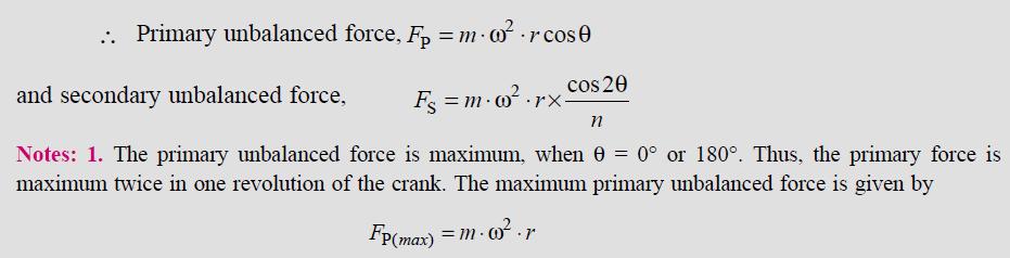
11 Partial Balancing of Unbalanced Primary Force in a Reciprocating Engine Now, Fp = (m ω^2 r) cosθ Also, Fp = component of the centrifugal force produced by a rotating mass m placed at the crank radius r; We can consider that some weight is at C & balance it.

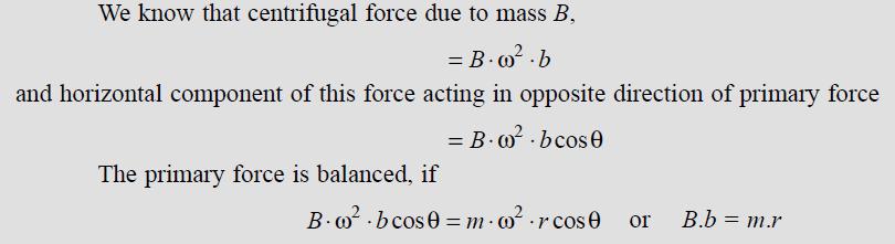
12 The primary force acts from O to P along the line of stroke. This is balanced by having a mass B at a radius b, placed diametrically opposite to the crank pin C.
13
14 There is also a vertical component of Mass B = B ω^2 bsin θ. This force remains unbalanced. The maximum value of this force is equal to B ω^2 b when θ is 90 and 270, & is = maximum value of the primary force m ω^2 r.
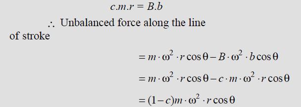
15 This method of balancing, changes the direction of the maximum unbalanced force from the line of stroke to the perpendicular to line of stroke. As a compromise let a fraction c of the reciprocating masses is balanced, such that
16
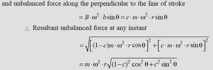
17

18 So here we are balancing some of reciprocating and some of rotary masses, by Bb.
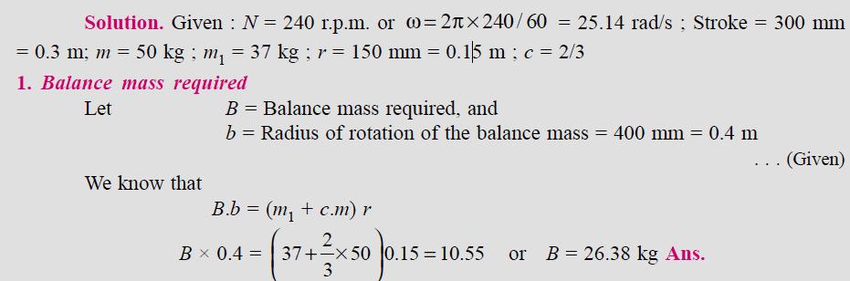
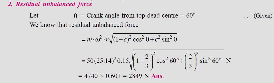
19 Example A single cylinder reciprocating engine has speed 240 r.p.m., stroke 300 mm, mass of reciprocating parts 50 kg, mass of revolving parts at 150 mm radius is 37 kg. If two-third of the reciprocating parts and all the revolving parts are to be balanced, find : 1. The balance mass required at a radius of 400 mm, and 2. The residual unbalanced force when the crank has rotated 60 from top dead centre.
20
21
22 Partial Balancing of Locomotives (Trains) Usually, there are two cylinders and their cranks are placed at right angles to each other, to have uniformity in turning moment diagram. The two cylinder locomotives are classified as : 4.Inside cylinder locomotives; 5.Outside cylinder locomotives. In the inside cylinder locomotives, the two cylinders are placed in between the planes of two driving wheels as shown in Fig (a).
23 whereas in the outside cylinder locomotives, the two cylinders are placed outside the driving wheels, one on each side of the driving wheel, as shown in Fig (b).
24 Further classification: The locomotives may be (d)single or uncoupled locomotives ; and (e)coupled locomotives. A single or uncoupled locomotive is one, in which the effort is transmitted to one pair of the wheels only ; whereas in coupled locomotives, the driving wheels are connected to the leading and trailing wheel by an outside coupling rod.
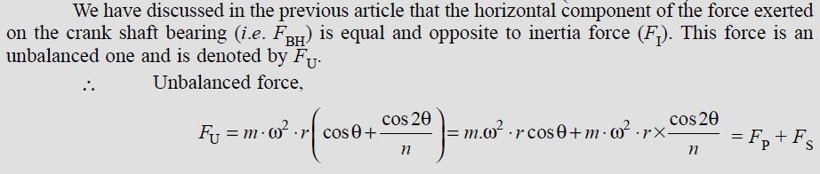
25 Effect of Partial Balancing of Reciprocating Parts of Two Cylinder Locomotives We have discussed in the previous article that the reciprocating parts are only partially balanced. Due to this partial balancing of the reciprocating parts, there is an unbalanced primary force along the line of stroke and also an unbalanced primary force perpendicular to the line ofstroke. The effect of an unbalanced primary force along the line of stroke is to produce; 1. Variation in tractive force along the line of stroke ; and 2. Swaying couple.
26 The effect of an unbalanced primary force perpendicular to the line of stroke produce variation in pressure on the rails, which results in hammering action on the rails. The maximum magnitude of the unbalanced force along the perpendicular to the line of stroke is known as a hammer blow.
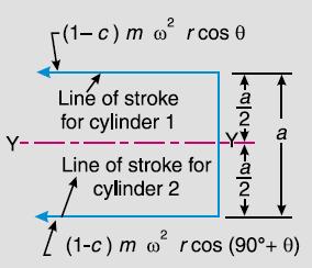
27 Variation of Tractive Force The resultant unbalanced force due to the two cylinders, along the line of stroke, is known as tractive force. Let the crank for the first cylinder be inclined at an angle θ with the line of stroke, as shown in Fig Since the crank for the second cylinder is at right angle to the first crank, therefore the angle of inclination for the second crank will be (90 + θ ). Let m = Mass of the reciprocating parts per cylinder, and c = Fraction of the reciprocating parts to be balanced.


28 Note: Cos(90 + theta) = - sin (theta)

29
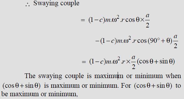
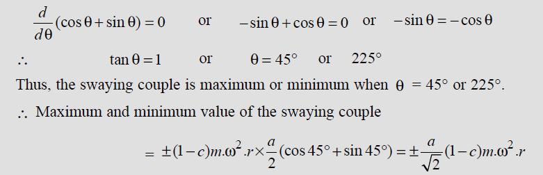
30 Swaying Couple The unbalanced forces along the line of stroke for the two cylinders constitute a couple about the centre line YY between the cylinders as shown in Fig. This couple has swaying effect about a vertical axis, and tends to sway the engine alternately in clockwise and anticlockwise directions. Hence the couple is known as swaying couple. Let a = Distance between the centre lines of the two cylinders.
31
32
33 Note : In order to reduce the magnitude of the swaying couple, revolving balancing masses are introduced. But, as discussed in the previous article, the revolving balancing masses cause unbalanced forces to act at right angles to the line of stroke.
34 These forces vary the downward pressure of the wheels on the rails and cause oscillation of the locomotive in a vertical plane about a horizontal axis. Since a swaying couple is more harmful than an oscillating couple, therefore a value of c from 2/3 to 3/4, in two-cylinder locomotives with two pairs of coupled wheels, is usually used. But in large four cylinder locomotives with three or more pairs of coupled wheels, the value of c is taken as 2/5.
III B.Tech I Semester Supplementary Examinations, May/June
 Set No. 1 III B.Tech I Semester Supplementary Examinations, May/June - 2015 1 a) Derive the expression for Gyroscopic Couple? b) A disc with radius of gyration of 60mm and a mass of 4kg is mounted centrally
R10 Set No: 1 ''' ' '' '' '' Code No: R31033
 R10 Set No: 1 III B.Tech. I Semester Regular and Supplementary Examinations, December - 2013 DYNAMICS OF MACHINERY (Common to Mechanical Engineering and Automobile Engineering) Time: 3 Hours Max Marks:
B.TECH III Year I Semester (R09) Regular & Supplementary Examinations November 2012 DYNAMICS OF MACHINERY
 Regular & Supplementary Examinations November 2012 DYNAMICS OF MACHINERY") 1 B.TECH III Year I Semester (R09) Regular & Supplementary Examinations November 2012 DYNAMICS OF MACHINERY (Mechanical Engineering) Time: 3 hours Max. Marks: 70 Answer any FIVE questions All questions
1 B.TECH III Year I Semester (R09) Regular & Supplementary Examinations November 2012 DYNAMICS OF MACHINERY (Mechanical Engineering) Time: 3 hours Max. Marks: 70 Answer any FIVE questions All questions
Chapter 15. Inertia Forces in Reciprocating Parts
 Chapter 15 Inertia Forces in Reciprocating Parts 2 Approximate Analytical Method for Velocity and Acceleration of the Piston n = Ratio of length of ConRod to radius of crank = l/r 3 Approximate Analytical
Chapter 15. Inertia Forces in Reciprocating Parts
 Chapter 15 Inertia Forces in Reciprocating Parts 2 Approximate Analytical Method for Velocity & Acceleration of the Piston n = Ratio of length of ConRod to radius of crank = l/r 3 Approximate Analytical
UNIT 5 Balancing of Reciprocating Masses
 UNIT 5 Balancing of Reciprocating Masses 1.Obtain an expression for primary forces for V engine having two identical cylinders lying in a plane. The included angle between the cylinder centre line is 22.
CHAPTER 1 BALANCING BALANCING OF ROTATING MASSES
 CHAPTER 1 BALANCING Dynamics of Machinery ( 2161901) 1. Attempt the following questions. I. Need of balancing II. Primary unbalanced force in reciprocating engine. III. Explain clearly the terms static
KINEMATICS OF MACHINARY UBMC302 QUESTION BANK UNIT-I BASICS OF MECHANISMS PART-A
 KINEMATICS OF MACHINARY UBMC302 QUESTION BANK UNIT-I BASICS OF MECHANISMS PART-A 1. Define the term Kinematic link. 2. Classify kinematic links. 3. What is Mechanism? 4. Define the terms Kinematic pair.
Part B Problem 1 In a slider crank mechanicsm the length of the crank and connecting rod are 150mm and
 SRI RAMAKRISHNA INSTITUTE OF TECHNOLOGY, COIMBATORE-10 (Approved by AICTE, New Delhi Affiliated to Anna University, Chennai) Answer Key Part A 1) D Alembert s Principle It states that the inertia forces
Introduction. Types of Governors. The governors may, broadly, be classified as. 1. Centrifugal governors, and 2. Inertia governors.
 TOM Governor Assi. Professor Mechanical Engineering Department Introduction The function of a governor is to regulate the mean speed of an engine, when there are variations in the load e.g. when the load
Dynamics of Machines. Prof. Amitabha Ghosh. Department of Mechanical Engineering. Indian Institute of Technology, Kanpur. Module No.
 Dynamics of Machines Prof. Amitabha Ghosh Department of Mechanical Engineering Indian Institute of Technology, Kanpur Module No. # 05 Lecture No. # 01 V & Radial Engine Balancing In the last session, you
Dynamics of Machines. Prof. Amitabha Ghosh. Department of Mechanical Engineering. Indian Institute of Technology, Kanpur. Module No.
 Dynamics of Machines Prof. Amitabha Ghosh Department of Mechanical Engineering Indian Institute of Technology, Kanpur Module No. # 04 Lecture No. # 03 In-Line Engine Balancing In the last session, you
Fatima Michael College of Engineering & Technology
 DEPARTMENT OF MECHANICAL ENGINEERING STAFF NAME: Mr.M. BEJU MOHAN M.E., SUBJECT: ME6505-DYNAMICS OF MACHINES QUESTION BANK YEAR/SEM: III/V UNIT-I (FORCE ANALYSIS) PART-A (2 marks) 1. State the principle
UNIT - III GYROSCOPE
 UNIT - III GYROSCOPE Introduction 1When a body moves along a curved path, a force in the direction of centripetal acceleration (centripetal force ) has to be applied externally This external force is known
Analysis of Parametric Studies on the Impact of Piston Velocity Profile On the Performance of a Single Cylinder Diesel Engine
 IOSR Journal of Mechanical and Civil Engineering (IOSR-JMCE) e-issn: 2278-1684,p-ISSN: 2320-334X, Volume 12, Issue 2 Ver. II (Mar - Apr. 2015), PP 81-85 www.iosrjournals.org Analysis of Parametric Studies
B.Tech. MECHANICAL ENGINEERING (BTMEVI) Term-End Examination December, 2012 BIMEE-007 : ADVANCED DYNAMICS OF MACHINE
 Term-End Examination December, 2012 BIMEE-007 : ADVANCED DYNAMICS OF MACHINE") No. of Printed Pages : 5 BIMEE-007 B.Tech. MECHANICAL ENGINEERING (BTMEVI) Term-End Examination 01601 December, 2012 BIMEE-007 : ADVANCED DYNAMICS OF MACHINE Time : 3 hours Maximum Marks : 70 Note : Attempt
No. of Printed Pages : 5 BIMEE-007 B.Tech. MECHANICAL ENGINEERING (BTMEVI) Term-End Examination 01601 December, 2012 BIMEE-007 : ADVANCED DYNAMICS OF MACHINE Time : 3 hours Maximum Marks : 70 Note : Attempt
1.1 : Kinematics of Machines
 1.1 : Kinematics of Machines ---------------------------------------------------------------------------------- Q.1.Define Statics, Dynamics, Kinetics and kinematics. Ans: Statics :- It is the branch of
VTU EDUSAT PROGRAMME -17 DYNAMICS OF MACHINES (10 ME 54) Unit-7 ADARSHA H G GYROSCOPE
 Unit-7 ADARSHA H G GYROSCOPE") VTU EDUSAT PROGRAMME -17 DYNAMICS OF MACHINES (10 ME 54) 1.0 INTRODUCTION Unit-7 GYROSCOPE Gyre is a Greek word, meaning circular motion and Gyration means the whirling motion. A gyroscope is a spatial
VTU EDUSAT PROGRAMME -17 DYNAMICS OF MACHINES (10 ME 54) 1.0 INTRODUCTION Unit-7 GYROSCOPE Gyre is a Greek word, meaning circular motion and Gyration means the whirling motion. A gyroscope is a spatial
Analytical method of finding velocity and acceleration in slider crank mechanism
 Analytical method of finding velocity and acceleration in slider crank mechanism Formulae for Analytical method of finding velocity and acceleration in slider crank mechanism Ratio n = connecting rod length
INSTITUTE OF AERONAUTICAL ENGINEERING (Autonomous) Dundigal, Hyderabad
 Dundigal, Hyderabad") INSTITUTE OF AERONAUTICAL ENGINEERING (Autonomous) Dundigal, Hyderabad -500 043 MECHANICAL ENGINEERING TUTORIAL QUESTION BANK Course Name Course Code Class Branch : DYNAMICS OF MACHINERY : A50317 : III
INSTITUTE OF AERONAUTICAL ENGINEERING (Autonomous) Dundigal, Hyderabad -500 043 MECHANICAL ENGINEERING TUTORIAL QUESTION BANK Course Name Course Code Class Branch : DYNAMICS OF MACHINERY : A50317 : III
Theory of Machines. CH-1: Fundamentals and type of Mechanisms
 CH-1: Fundamentals and type of Mechanisms 1. Define kinematic link and kinematic chain. 2. Enlist the types of constrained motion. Draw a label sketch of any one. 3. Define (1) Mechanism (2) Inversion
ME6401 KINEMATICS OF MACHINERY UNIT- I (Basics of Mechanism)
") ME6401 KINEMATICS OF MACHINERY UNIT- I (Basics of Mechanism) 1) Define resistant body. 2) Define Link or Element 3) Differentiate Machine and Structure 4) Define Kinematic Pair. 5) Define Kinematic Chain.
ME6401 KINEMATICS OF MACHINERY UNIT- I (Basics of Mechanism) 1) Define resistant body. 2) Define Link or Element 3) Differentiate Machine and Structure 4) Define Kinematic Pair. 5) Define Kinematic Chain.
Technical Report Con Rod Length, Stroke, Piston Pin Offset, Piston Motion and Dwell in the Lotus-Ford Twin Cam Engine. T. L. Duell.
 Technical Report - 1 Con Rod Length, Stroke, Piston Pin Offset, Piston Motion and Dwell in the Lotus-Ford Twin Cam Engine by T. L. Duell May 24 Terry Duell consulting 19 Rylandes Drive, Gladstone Park
DHANALAKSHMI COLLEGE OF ENGINEERING
 DHANALAKSHMI COLLEGE OF ENGINEERING (Dr.VPR Nagar, Manimangalam, Tambaram) Chennai - 601 301 DEPARTMENT OF MECHANICAL ENGINEERING III YEAR MECHANICAL - VI SEMESTER ME 6601 DESIGN OF TRANSMISSION SYSTEMS
10/29/2018. Chapter 16. Turning Moment Diagrams and Flywheel. Mohammad Suliman Abuhaiba, Ph.D., PE
 1 Chapter 16 Turning Moment Diagrams and Flywheel 2 Turning moment diagram (TMD) graphical representation of turning moment or crank-effort for various positions of the crank 3 Turning Moment Diagram for
FRICTION DEVICES: DYNAMOMETER. Presented by: RONAK D. SONI Assistant Professor Parul Institute of Technology, Parul University
 FRICTION DEVICES: DYNAMOMETER Presented by: RONAK D. SONI Assistant Professor Parul Institute of Technology, Parul University DYNAMOMETER A dynamometer is a brake but in addition it has a device to measure
MLR Institute oftechnology
 MLR Institute oftechnology Dundigal, Hyderabad - 500 043 MECHANICAL ENGINEERING Assignment Questions DYNAMICS OF MACHINERY Course Title Course Code 55012 Regulation R13 Course Structure Lectures Tutorials
Steam Engine Valves and Reversing Gears
 612 l Theory of Machines 17 Features 1. Introduction. 2. D-slide Valve. 3. Piston Slide Valve. 4. Relative Positions of Crank and Eccentric Centre Lines. 5. Crank Positions for Admission, Cut off, Release
FIRSTRANKER. 2. (a) Distinguish (by neat sketches) betweenpeaucellier mechanism and Hart mechanism.
 Distinguish (by neat sketches) betweenpeaucellier mechanism and Hart mechanism.") Code No: 07A51404 R07 Set No. 2 IIIB.Tech I Semester Examinations,May 2011 KINEMATICS OF MACHINERY Mechatronics Time: 3 hours Max Marks: 80 Answer any FIVE Questions All Questions carry equal marks 1.
Code No: 07A51404 R07 Set No. 2 IIIB.Tech I Semester Examinations,May 2011 KINEMATICS OF MACHINERY Mechatronics Time: 3 hours Max Marks: 80 Answer any FIVE Questions All Questions carry equal marks 1.
WEEK 4 Dynamics of Machinery
 WEEK 4 Dynamics of Machinery References Theory of Machines and Mechanisms, J.J.Uicker, G.R.Pennock ve J.E. Shigley, 2003 Prof.Dr.Hasan ÖZTÜRK 1 DYNAMICS OF RECIPROCATING ENGINES Prof.Dr.Hasan ÖZTÜRK The
THEORY OF MACHINES FRICTION CLUTCHES
 THEORY OF MACHINES FRICTION CLUTCHES Introduction A friction clutch has its principal application in the transmission of power of shafts and machines which must be started and stopped frequently. Its application
SYLLABUS. osmania university. Force Analysis of Four-Bar and Slider Crank Mechanisms. CHAPTER - 2 : DYNAMIC FORCE ANALYSIS
 Contents i SYLLABUS osmania university UNIT - I CHAPTER - 1 : STATIC TIC FORCE ANALYSIS Force Analysis of Four-Bar and Slider Crank Mechanisms. CHAPTER - 2 : DYNAMIC FORCE ANALYSIS Force Analysis of Four-Bar
Code No: R Set No. 1
 Code No: R05310304 Set No. 1 III B.Tech I Semester Regular Examinations, November 2007 KINEMATICS OF MACHINERY ( Common to Mechanical Engineering, Mechatronics, Production Engineering and Automobile Engineering)
Subject with Code: Kinematic of Machinery (16ME304)Course & Branch: B. Tech - ME Year &Sem : II-B. Tech &I-Sem Regulation: R16
Course & Branch: B. Tech - ME Year &Sem : II-B. Tech &I-Sem Regulation: R16") SIDDHARTH INSTITUTE OF ENGINEERING &TECHNOLOGY:: PUTTUR (Approved by AICTE, New Delhi & Affiliated to JNTUA, Anantapuramu) (Accredited by NBA & Accredited by NAAC with A Grade) (An ISO 9001:2008 Certified
SIDDHARTH INSTITUTE OF ENGINEERING &TECHNOLOGY:: PUTTUR (Approved by AICTE, New Delhi & Affiliated to JNTUA, Anantapuramu) (Accredited by NBA & Accredited by NAAC with A Grade) (An ISO 9001:2008 Certified
1. (a) Discuss various types of Kinematic links with examples. (b) Explain different types of constrained motions with examples.
 Discuss various types of Kinematic links with examples. (b) Explain different types of constrained motions with examples.") Code No: RR310304 Set No. 1 III B.Tech I Semester Supplementary Examinations, February 2007 KINEMATICS OF MACHINERY ( Common to Mechanical Engineering, Mechatronics and Production Engineering) Time: 3
Code No: RR310304 Set No. 1 III B.Tech I Semester Supplementary Examinations, February 2007 KINEMATICS OF MACHINERY ( Common to Mechanical Engineering, Mechatronics and Production Engineering) Time: 3
10/29/2013. Chapter 9. Mechanisms with Lower Pairs. Dr. Mohammad Abuhiba, PE
 Chapter 9 Mechanisms with Lower Pairs 1 2 9.1. Introduction When the two elements of a pair have a surface contact and a relative motion takes place, the surface of one element slides over the surface
df Idl B (1) cst ) the resulting force acting of a F Idl B IL B (2) GOAL I. INTRODUCTION. II. OPERATION PRINCIPLE
 cst ) the resulting force acting of a F Idl B IL B (2) GOAL I. INTRODUCTION. II. OPERATION PRINCIPLE") GOAL The goal of this experiment is to better understand the processes used in electric generators and motors, using simple models, that are close to actual machines. We suggest the students first focus
GOAL The goal of this experiment is to better understand the processes used in electric generators and motors, using simple models, that are close to actual machines. We suggest the students first focus
AT 2303 AUTOMOTIVE POLLUTION AND CONTROL Automobile Engineering Question Bank
 AT 2303 AUTOMOTIVE POLLUTION AND CONTROL Automobile Engineering Question Bank UNIT I INTRODUCTION 1. What are the design considerations of a vehicle?(jun 2013) 2..Classify the various types of vehicles.
Motional emf. as long as the velocity, field, and length are mutually perpendicular.
 Motional emf Motional emf is the voltage induced across a conductor moving through a magnetic field. If a metal rod of length L moves at velocity v through a magnetic field B, the motional emf is: ε =
BIMEE-007 B.Tech. MECHANICAL ENGINEERING (BTMEVI) Term-End Examination December, 2013
 Term-End Examination December, 2013") No. of Printed Pages : 5 BIMEE-007 B.Tech. MECHANICAL ENGINEERING (BTMEVI) Term-End Examination December, 2013 0 0 9 0 9 BIMEE-007 : ADVANCED DYNAMICS OF MACHINE Time : 3 hours Maximum Marks : 70 Note
No. of Printed Pages : 5 BIMEE-007 B.Tech. MECHANICAL ENGINEERING (BTMEVI) Term-End Examination December, 2013 0 0 9 0 9 BIMEE-007 : ADVANCED DYNAMICS OF MACHINE Time : 3 hours Maximum Marks : 70 Note
I.C ENGINES. CLASSIFICATION I.C Engines are classified according to:
 I.C ENGINES An internal combustion engine is most popularly known as I.C. engine, is a heat engine which converts the heat energy released by the combustion of the fuel taking place inside the engine cylinder
2. a) What is pantograph? What are its uses? b) Prove that the peaucellier mechanism generates a straight-line motion. (5M+10M)
 What is pantograph? What are its uses? b) Prove that the peaucellier mechanism generates a straight-line motion. (5M+10M)") Code No: R22032 R10 SET - 1 1. a) Define the following terms? i) Link ii) Kinematic pair iii) Degrees of freedom b) What are the inversions of double slider crank chain? Describe any two with neat sketches.
Code No: R22032 R10 SET - 1 1. a) Define the following terms? i) Link ii) Kinematic pair iii) Degrees of freedom b) What are the inversions of double slider crank chain? Describe any two with neat sketches.
Code No: R Set No. 1
 Code No: R05222106 Set No. 1 II B.Tech II Semester Supplimentary Examinations, Aug/Sep 2007 MECHANISMS AND MECHANICAL DESIGN (Aeronautical Engineering) Time: 3 hours Max Marks: 80 Answer any FIVE Questions
LABORATORY MANUAL DYNAMICS OF MACHINE LAB
 LABORATORY MANUAL DYNAMICS OF MACHINE LAB Sr. No Experiment Title 1 To Perform Experiment On Watt And Porter Governors To Prepare Performance Characteristic Curves, And To Find Stability & Sensitivity
INDEX UNIT- IV MECHANISM FOR CONTROL (1) Introduction (2) Principle of Working (3) Classification of governors (4) Height of governor (5) Sleeve lift
 Introduction (2) Principle of Working (3) Classification of governors (4) Height of governor (5) Sleeve lift") INDEX UNIT- IV MECHANISM FOR CONTROL (1) Introduction (2) Principle of Working (3) Classification of governors (4) Height of governor (5) Sleeve lift (6) Isochronism s (7) Stability (8) Hunting (9) Sensitiveness
INDEX UNIT- IV MECHANISM FOR CONTROL (1) Introduction (2) Principle of Working (3) Classification of governors (4) Height of governor (5) Sleeve lift (6) Isochronism s (7) Stability (8) Hunting (9) Sensitiveness
Design, Analysis &Optimization of Crankshaft Using CAE
 Design, Analysis &Optimization of Crankshaft Using CAE Dhekale Harshada 1, Jagtap Ashwini 2, Lomte Madhura 3, Yadav Priyanka 4 1,2,3,4 Government College of Engineering and Research Awasari, Department
ISSN: [Sheikh* et al., 6(2): February, 2017] Impact Factor: 4.116
![ISSN: [Sheikh* et al., 6(2): February, 2017] Impact Factor: 4.116](/thumbs/86/94119536.jpg "ISSN: [Sheikh* et al., 6(2): February, 2017] Impact Factor: 4.116") IJESRT INTERNATIONAL JOURNAL OF ENGINEERING SCIENCES & RESEARCH TECHNOLOGY COMPUTER AIDED MODELING AND ANALYSIS OF CRANK AND SLOTTED LEVER QUICK RETURN MECHANISM Shahbaz.M. Sheikh *, Sujata.P. Khartade,
IJESRT INTERNATIONAL JOURNAL OF ENGINEERING SCIENCES & RESEARCH TECHNOLOGY COMPUTER AIDED MODELING AND ANALYSIS OF CRANK AND SLOTTED LEVER QUICK RETURN MECHANISM Shahbaz.M. Sheikh *, Sujata.P. Khartade,
Design and Analysis of Four Cylinder Diesel Engine Balancer Shaft
 Design and Analysis of Four Cylinder Diesel Engine Balancer Shaft Gopal Kumar Kumhar M. Tech CAD/CAM VIT University Vandalur - Kelambakkam Road, Chennai, Tamil Nadu-600048 Shakti Kumar Singh Chief Manager
Comparative Study Of Four Stroke Diesel And Petrol Engine.
 Comparative Study Of Four Stroke Diesel And Petrol Engine. Aim: To study the construction and working of 4- stroke petrol / diesel engine. Theory: A machine or device which derives heat from the combustion
A Novel Device to Measure Instantaneous Swept Volume of Internal Combustion Engines
 Global Journal of Researches in Engineering Vol. 10 Issue 7 (Ver1.0), December 2010 P a g e 47 A Novel Device to Measure Instantaneous Swept Volume of Internal Combustion Engines MURUGAN. R. GJRE -A Classification
Instantaneous Centre Method
 Instantaneous Centre Method The combined motion of rotation and translation of the link AB may be assumed to be a motion of pure rotation about some centre I, known as the instantaneous centre of rotation.
12/25/2015. Chapter 20. Cams. Mohammad Suliman Abuhiba, Ph.D., PE
 Chapter 20 Cams 1 2 Introduction A cam: a rotating machine element which gives reciprocating or oscillating motion to another element (follower) Cam & follower have a line constitute a higher pair. of
MODIFICATION OF SLIDER CRANK MECHANISM AND STUDY OF THE CURVES ASSOCIATED WITH IT
 MODIFICATION OF SLIDER CRANK MECHANISM AND STUDY OF THE CURVES ASSOCIATED WITH IT Samiron Neog 1, Deep Singh 2, Prajnyan Ballav Goswami 3 1,2,3 Student,B. Tech.,Mechanical, Dibrugarh University Institute
INDEX. UNIT I - Force Analysis
 INDEX UNIT I - Force Analysis (1) Introduction (2) Newton s Law (3) Types of force Analysis (4) Principle of Super Position (5) Free Body Diagram (6) D Alemberts Principle (7) Dynamic Analysis of Four
PRELIMINARY DESIGN OF TWIN-CYLINDER ENGINES FOR HYBRID ELECTRIC VEHICLE APPLICATIONS
 PRELIMINARY DESIGN OF TWIN-CYLINDER ENGINES FOR HYBRID ELECTRIC VEHICLE APPLICATIONS Abstract Yannick Louvigny, Sébastien Christiaens and Pierre Duysinx LTAS Automotive Engineering, University of Liège
Physics12 Unit 8/9 Electromagnetism
 Name: Physics12 Unit 8/9 Electromagnetism 1. An electron, travelling with a constant velocity, enters a region of uniform magnetic field. Which of the following is not a possible pathway? 2. A bar magnet
smartworld.asia UNIT III Clutches: Friction clutches- Single Disc or plate clutch, Multiple Disc Clutch, Cone Clutch, Centrifugal Clutch.
 SYLLABUS UNIT I PRECESSION : Gyroscopes, effect of precession motion on the stability of moving vehicles such as motor car, motor cycle, aero planes and ships. Static and dynamic force analysis of planar
TECHNOLOGY MECHANISMS
 TECHNOLOGY MECHANISMS 3º ESO IES CHAN DO MONTE URTAZA 1 WHAT IS A MECHANISM? Mechanism are devices that have been designed to make jobs easier. They all have certain things in common: They involve some
Flywheel. 776 A Textbook of Machine Design
 776 A Textbook of Machine Design C H A P T E R Flywheel 1. Introduction.. Coefficient of Fluctuation of Speed. 3. Fluctuation of Energy. 4. Maximum Fluctuation of Energy. 5. Coefficient of Fluctuation
GENERAL BALANCE INTRODUCTION. Balanced engines generally:
 Engine Balance Ken Helmick Metal Model Maker General Motors Powertrain This article is intended to give the reader an appreciation for the processes necessary to build balanced engines. GENERAL BALANCE
Simple Gears and Transmission
 Simple Gears and Transmission Simple Gears and Transmission page: of 4 How can transmissions be designed so that they provide the force, speed and direction required and how efficient will the design be?
CH16: Clutches, Brakes, Couplings and Flywheels
 CH16: Clutches, Brakes, Couplings and Flywheels These types of elements are associated with rotation and they have in common the function of dissipating, transferring and/or storing rotational energy.
UNIT - 3 Friction and Belt Drives
 UNIT - 3 Friction and Belt Drives 1.State the laws of dynamic or kinetic friction (03 Marks) (June 2015) Laws of Kinetic or Dynamic Friction Following are the laws of kinetic or dynamic friction: 1. The
Moments. It doesn t fall because of the presence of a counter balance weight on the right-hand side. The boom is therefore balanced.
 Moments The crane in the image below looks unstable, as though it should topple over. There appears to be too much of the boom on the left-hand side of the tower. It doesn t fall because of the presence
10. Starting Method for Induction Motors
 10. Starting Method for Induction Motors A 3-phase induction motor is theoretically self starting. The stator of an induction motor consists of 3-phase windings, which when connected to a 3-phase supply
American International Journal of Research in Science, Technology, Engineering & Mathematics INDIA
 American International Journal of Research in Science, Technology, Engineering & Mathematics Available online at http://www.iasir.net ISSN (Print): 2328-3491, ISSN (Online): 2328-3580, ISSN (CD-ROM): 2328-3629
ELECTRO MAGNETIC INDUCTION
 6 ELECTRO MAGNETIC INDUCTION 06.01 Electromagnetic induction When the magnetic flux linked with a coil or conductor changes, an emf is developed in it. This phenomenon is known as electromagnetic induction.
COOPERATIVE PATENT CLASSIFICATION
 CPC F COOPERATIVE PATENT CLASSIFICATION MECHANICAL ENGINEERING; LIGHTING; HEATING; WEAPONS; BLASTING (NOTE omitted) ENGINES OR PUMPS F01 MACHINES OR ENGINES IN GENERAL (combustion engines F02; machines
(POWER TRANSMISSION Methods)
") UNIT-5 (POWER TRANSMISSION Methods) It is a method by which you can transfer cyclic motion from one place to another or one pulley to another pulley. The ways by which we can transfer cyclic motion are:-
UNIT-5 (POWER TRANSMISSION Methods) It is a method by which you can transfer cyclic motion from one place to another or one pulley to another pulley. The ways by which we can transfer cyclic motion are:-
Department of Mechanical Engineering University of Engineering & Technology Lahore(KSK Campus).
.") Department of Mechanical Engineering University of Engineering & Technology Lahore(KSK Campus). LAB DATA Lab Incharge: Engr. Muhammad Amjad Lab Assistant: Abbas Ali Lay-Out of Mechanics of Machines Lab
Department of Mechanical Engineering University of Engineering & Technology Lahore(KSK Campus). LAB DATA Lab Incharge: Engr. Muhammad Amjad Lab Assistant: Abbas Ali Lay-Out of Mechanics of Machines Lab
Phys102 Lecture 20/21 Electromagnetic Induction and Faraday s Law
 Phys102 Lecture 20/21 Electromagnetic Induction and Faraday s Law Key Points Induced EMF Faraday s Law of Induction; Lenz s Law References SFU Ed: 29-1,2,3,4,5,6. 6 th Ed: 21-1,2,3,4,5,6,7. Induced EMF
STUDY AND ANALYSIS OF CONNECTING ROD PARAMETERS USING ANSYS
 International Journal of Mechanical Engineering and Technology (IJMET) Volume 7, Issue 4, July Aug 2016, pp.212 220, Article ID: IJMET_07_04_022 Available online at http://www.iaeme.com/ijmet/issues.asp?jtype=ijmet&vtype=7&itype=4
Simple Gears and Transmission
 Simple Gears and Transmission Contents How can transmissions be designed so that they provide the force, speed and direction required and how efficient will the design be? Initial Problem Statement 2 Narrative
The University of Melbourne Engineering Mechanics
 The University of Melbourne 436-291 Engineering Mechanics Tutorial Twelve General Plane Motion, Work and Energy Part A (Introductory) 1. (Problem 6/78 from Meriam and Kraige - Dynamics) Above the earth
Design and Analysis of a Lightweight Crankshaft for a Racing Motorcycle Engine. Naji Zuhdi, PETRONAS Phil Carden, Ricardo UK David Bell, Ricardo UK
 Design and Analysis of a Lightweight Crankshaft for a Racing Motorcycle Engine Naji Zuhdi, PETRONAS Phil Carden, Ricardo UK David Bell, Ricardo UK Contents Introduction Design overview Engine balance Main
A New Device to Measure Instantaneous Swept Volume of Reciprocating Machines/Compressors
 Purdue University Purdue e-pubs International Compressor Engineering Conference School of Mechanical Engineering 2004 A New Device to Measure Instantaneous Swept Volume of Reciprocating Machines/Compressors
INTRODUCTION: Rotary pumps are positive displacement pumps. The rate of flow (discharge) of rotary pump remains constant irrespective of the
 of rotary pump remains constant irrespective of the") INTRODUCTION: Rotary pumps are positive displacement pumps. The rate of flow (discharge) of rotary pump remains constant irrespective of the pressure. That is, even at very high pressure, these pumps can
INTRODUCTION: Rotary pumps are positive displacement pumps. The rate of flow (discharge) of rotary pump remains constant irrespective of the pressure. That is, even at very high pressure, these pumps can
Physics 121 Practice Problem Solutions 11 Faraday s Law of Induction
 Physics 121 Practice Problem Solutions 11 Faraday s Law of Induction Contents: 121P11-1P, 3P,4P, 5P, 7P, 17P, 19P, 24P, 27P, 28P, 31P Overview Magnetic Flux Motional EMF Two Magnetic Induction Experiments
6: Vehicle Performance
 6: Vehicle Performance 1. Resistance faced by the vehicle a. Air resistance It is resistance offered by air to the forward movement of vehicle. This resistance has an influence on performance, ride and
Product design: Mechanical systems
 Product design: Mechanical systems Recall Mechanisms can: change direction of movement, e.g. from clockwise to anticlockwise or from horizontal to vertical; change type of movement, e.g. from rotating
What are the functions of gears? What is gear?
 8//0 hapter seven Laith atarseh are very important in power transmission between a drive rotor and driven rotor What are the functions of gears? - Transmit motion and torque (power) between shafts - Maintain
AP Physics B: Ch 20 Magnetism and Ch 21 EM Induction
 Name: Period: Date: AP Physics B: Ch 20 Magnetism and Ch 21 EM Induction MULTIPLE CHOICE. Choose the one alternative that best completes the statement or answers the question. 1) If the north poles of
Angular Momentum Problems Challenge Problems
 Angular Momentum Problems Challenge Problems Problem 1: Toy Locomotive A toy locomotive of mass m L runs on a horizontal circular track of radius R and total mass m T. The track forms the rim of an otherwise
CHAPTER 6 GEARS CHAPTER LEARNING OBJECTIVES
 CHAPTER 6 GEARS CHAPTER LEARNING OBJECTIVES Upon completion of this chapter, you should be able to do the following: Compare the types of gears and their advantages. Did you ever take a clock apart to
Chapter seven. Gears. Laith Batarseh
 Chapter seven Gears Laith Batarseh Gears are very important in power transmission between a drive rotor and driven rotor What are the functions of gears? - Transmit motion and torque (power) between shafts
Design and Stress Analysis of Crankshaft for Single Cylinder 4-Stroke Diesel Engine
 Design and Stress Analysis of Crankshaft for Single Cylinder 4-Stroke Diesel Engine Amit Solanki #1, Jaydeepsinh Dodiya #2, # Mechanical Engg.Deptt, C.U.Shah University, Wadhwan city, Gujarat, INDIA Abstract
CHENDU COLLEGE OF ENGINEERING & TECHNOLOGY DEPARTMENT OF MECHANICAL ENGINEERING QUESTION BANK IV SEMESTER
 CHENDU COLLEGE OF ENGINEERING & TECHNOLOGY DEPARTMENT OF MECHANICAL ENGINEERING QUESTION BANK IV SEMESTER Sub Code: ME 6401 KINEMATICS OF MACHINERY UNIT-I PART-A 1. Sketch and define Transmission angle
 VALLIAMMAI ENGINEERING COLLEGE DEPARTMENT OF MECHANICAL ENGINEERING ME6401- KINEMATICS OF MACHINERY QUESTION BANK PART-A Unit 1-BASICS OF MECHANISMS 1. Define degrees of freedom. BT1 2. Describe spatial
Hours / 100 Marks Seat No.
 17412 16117 3 Hours / 100 Seat No. Instructions (1) All Questions are Compulsory. (2) Answer each next main Question on a new page. (3) Illustrate your answers with neat sketches wherever necessary. (4)
Bevel Gears. Fig.(1) Bevel gears
 Bevel gears") Bevel Gears Bevel gears are cut on conical blanks to be used to transmit motion between intersecting shafts. The simplest bevel gear type is the straighttooth bevel gear or straight bevel gear as can be
Bevel Gears Bevel gears are cut on conical blanks to be used to transmit motion between intersecting shafts. The simplest bevel gear type is the straighttooth bevel gear or straight bevel gear as can be
Homework # Physics 2 for Students of Mechanical Engineering
 Homework #10 203-1-1721 Physics 2 for Students of Mechanical Engineering Part A 3. In Fig. 34-41 below, the magnetic flux through the loop shown increases according to the relation B = (6 mwb/s 2 )t 2
Working Model 2D Tutorial 2
 Working Model 2D: Tutorial 2 Example 11-10: A wheel with Diameter of 1.2m, mounted in a vertical plane, accelerates uniformly from rest at 3 rad/s 2 for five seconds, and then maintains uniform velocity
St.MARTIN S ENGINEERING COLLEGE Dhulapally, Secunderabad
 St.MARTIN S ENGINEERING COLLEGE Dhulapally, Secunderabad-500 014 Subject: Kinematics of Machines Class : MECH-II Group A (Short Answer Questions) UNIT-I 1 Define link, kinematic pair. 2 Define mechanism
The characteristics of each type of service are given in table 1 given below:
 Types of Railway Services There are three types of passenger services which traction system has to cater for namely Urban, Sub-urban and Main line services. 1. Urban or city service In this type of service
UNIT IV DESIGN OF ENERGY STORING ELEMENTS. Prepared by R. Sendil kumar
 UNIT IV DESIGN OF ENERGY STORING ELEMENTS Prepared by R. Sendil kumar SPRINGS: INTRODUCTION Spring is an elastic body whose function is to distort when loaded and to recover its original shape when the
Module 2 : Dynamics of Rotating Bodies; Unbalance Effects and Balancing of Inertia Forces
 Module 2 : Dynamics of Rotating Bodies; Unbalance Effects and Balancing of Inertia Forces Lecture 3 : Concept of unbalance; effect of unbalance Objectives In this lecture you will learn the following Unbalance
MAGNETIC EFFECTS ON AND DUE TO CURRENT-CARRYING WIRES
 22 January 2013 1 2013_phys230_expt3.doc MAGNETIC EFFECTS ON AND DUE TO CURRENT-CARRYING WIRES OBJECTS To study the force exerted on a current-carrying wire in a magnetic field; To measure the magnetic
DEVELOPMENT OF A CONTROL MODEL FOR A FOUR WHEEL MECANUM VEHICLE. M. de Villiers 1, Prof. G. Bright 2
 de Villiers Page 1 of 10 DEVELOPMENT OF A CONTROL MODEL FOR A FOUR WHEEL MECANUM VEHICLE M. de Villiers 1, Prof. G. Bright 2 1 Council for Scientific and Industrial Research Pretoria, South Africa e-mail1:
Some science of balance Tony Foale 2007.
 Some science of balance Tony Foale 2007. Readers who started riding before the 1970s, will easily remember the incredible vibration that we used to have to suffer, particularly with British single and
Wheeled Mobile Robots
 Wheeled Mobile Robots Most popular locomotion mechanism Highly efficient on hard and flat ground. Simple mechanical implementation Balancing is not usually a problem. Three wheels are sufficient to guarantee