LINTECH. Positioning Systems INSTALLATION & SERVICE MANUAL. Front Cover. Registered by UL to ISO Certificate No. A6916
|
|
|
- Gilbert Atkinson
- 6 years ago
- Views:
Transcription
1 LINTECH Positioning Systems Front Cover INSTALLATION & SERVICE MANUAL Registered by UL to ISO 9001 Certificate No. A6916


2 Welcome to LINTECH Our local technical support group consists of Automation Specialists located throughout the United States & Canada. These Automation Specialists are experienced in the use of electronic and mechanical motion control products. They are well trained on the performance capabilities of LINTECH positioning components. LINTECH is constantly designing new products and improving upon the many options available with our standard products. Whether it is a standard or custom positioning system you need, please write, call, or us. We look forward to hearing from you. For the nearest Automation Specialist in your area call: For over thirty years LINTECH has designed, engineered, and manufactured linear & rotary positioning systems for use in a wide range of applications. Whether it is a standard positioning table, or a custom positioning system, LINTECH takes great pride in manufacturing a quality product. At LINTECH we are proud to provide the motion control user with this product guide. It was established to assist you with the design, selection, and implementation of mechanical positioning system. Depending on the requirements, standard positioning tables can often be assembled and shipped in less than 4 weeks. Custom positioning systems require a different approach. We evaluate your special application, use our many years of experience to guide you, and then manufacture a quality product designed to meet your performance specifications. Toll Free: Phone: Fax: Web Site: LINTECH 1845 Enterprise Way Monrovia, CA (800) (626) (626) lintech@lintechmotion.com Registered by UL to ISO 9001 Certificate No. A6916 LINTECH's technical support consists of a well trained inside customer service & application engineering staff, a team of experienced design engineers, a modernized CAD system, full functional CNC machines, and a versatile machining facility that is ISO 9001 certified. version: 12\2002 Copyright 2002 LINTECH
3 Table of Contents Introduction Overview Warranty & Returns Technical Assistance Standard Warranty Policy Return Policy Dimensions and Product Changes Specifications - Linear Positioning Systems Load Capacity Drive Mechanism Types Maximum Carriage Speed Maximum Carriage Acceleration & Thrust Carriage & Table Base Deflection Motor Size & Mounting Installation - Linear Positioning Tables Mounting Surface Requirements 110 Series Mounting Carriage & Table Base Modification Environmental Consideration Wiring Interface Maintenance - Linear Positioning Tables Lubrication Recommended Lubrication Types Guidelines for Lubrication Lubrication - Standard Tables Additional Installation - Linear Positioning Tables - Belt Drives 120 Series 180 Series 550 Series Options Motor Couplings Linear & Rotary Incremental Encoders Power-Off Electric Brakes End of Travel (EOT) & Home Switches Installation - Rotary Positioning Tables 300 Series 400 Series Pages
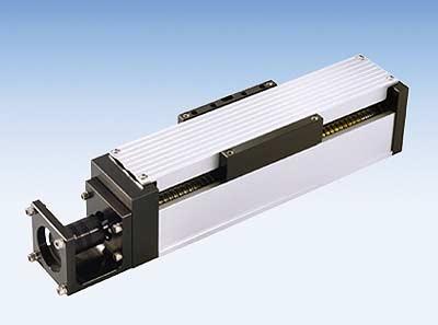
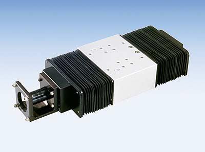
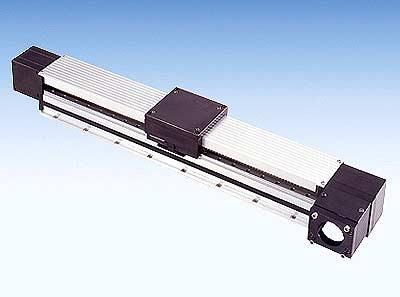
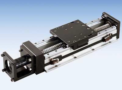
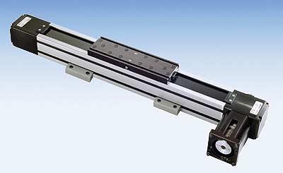
4 Introduction Overview Thank you for purchasing a LINTECH positioning system. This manual provides you with important information about your system. It also points out some precautions which should be taken to ensure proper operation, and the longest possible life of your system. LINTECH manufactures both standard and custom positioning systems which are used in a wide variety of applications and industries. The chart below illustrates the different positioning system models available from LINTECH and some of their basic features. For a full description and details on your system, please refer to the LINTECH Positioning Systems catalog or your original quotation if a custom system was purchased. Every LINTECH positioning system will have a "NAME PLATE" attached somewhere to the system, indicating the Model & Serial numbers. If, for any reason, you need to contact LINTECH, or an Automation Specialist, please have ready the Model & Serial numbers of your positioning system, as this may speed the process of answering your question. Table Series Positioning Type Bearing Type Drive Type 90 linear round rail (shaft) screw (acme or ball) 100 linear square (profile) rail screw (acme or ball) 110 linear square (profile) rail screw (acme or ball) 120 linear square (profile) rail belt 130 linear square (profile) rail screw (acme or ball) 150 linear square (profile) rail screw (acme or ball) 200 linear square (profile) rail screw (acme or ball) 250 linear square (profile) rail screw (acme or ball) 160 linear square (profile) rail screw (acme or ball) 170 linear square (profile) rail screw (acme or ball) 180 linear square (profile) rail belt 300 rotary angular contact worm gear 400 rotary angular contact worm gear 550 linear square (profile) rail belt Custom Positioning Systems - see individual quotations 2
5 Warranty & Returns Technical Assistance Please do not hesitate to call LINTECH with any questions you have. You may contact the Automation Specialist in your area for local help, visit our web site or call the factory direct. Either way, your satisfaction is our main concern. Toll Free: Phone: Fax: LINTECH 1845 Enterprise Way Monrovia, CA (800) (626) (626) Web Site: Standard Warranty Policy All LINTECH positioning systems are guaranteed to be free from defects in material and workmanship, under normal use, for a period of one year after date of shipment. This warranty covers the repair or replacement of a product when it is sent prepaid to LINTECH. LINTECH does not assume liability for installation, abuse, alteration, insufficient application data provided for a design, or misuse of any positioning system. Products furnished by LINTECH, but not manufactured by LINTECH (motors, gearheads, encoders, amplifiers, etc...), are subject to the manufacturers standard warranty terms and conditions. Return Policy Any product requiring a return to LINTECH (for warranty or non-warranty repair) requires pre-approval from the factory prior to shipment. Contact the customer service department at (800) in order to obtain a RMA (Return Materials Authorization) number. At that time, please have your system Model & Serial numbers available, along with the reason for the return. The RMA number should be clearly marked on the returned package label and your packing list, or shipping document. Return product freight prepaid in its original package, or one with comparable protection. LINTECH will not accept return shipments sent freight collect. Product damage incurred during return shipment, from poor packaging, will not be warranted by LINTECH. Keeping original packing materials is recommended until initial inspection & testing is completed. Dimensions and Product Changes Published dimensions shown in the Positioning Systems catalogs are known to be accurate at the time of printing. LINTECH shall not be held liable, under any circumstances, for any wrongly documented dimension or specification. Changes in design are made whenever LINTECH believes its product will improve by the change. No obligation to incorporate these changes in units manufactured prior to a change, will be assumed. 3
6 Specifications Load Capacity - Dynamic, Static, & Moment Loads It is very important to know the load capacity of your positioning table. If you purchased a standard catalog item, refer to the Positioning Systems catalog for load capacities. If a custom table was purchased, refer to your quote for the load rating. WARNING - exceeding the load capacity of your positioning table can result in table damage. Also, load ratings are based upon the utilization of ALL the carriage mounting holes for securing the load. If you are not sure what the load capacity of your positioning system is, please contact your local Automation Specialist or LINTECH. The dynamic horizontal load rating of a table is the amount of weight centered on the carriage that the table can support while moving. This value is rated for a specific travel life. If this value is exceeded, shorter travel life could result. Depending upon the application, this could mean the lead screw or linear bearings would need to be replaced before the rated travel life of the positioning system is reached. A static load occurs when a force is applied to the table carriage, with the carriage at zero speed. Typical static forces result from: drilling, grinding, pressing, cutting, welding, or even someone standing on the table. Exceeding the rated static load capacity of a table could result in structural damage to the positioning system. A Moment load occurs whenever the load center of gravity is not centered on the carriage, or when an external force is applied to the carriage (i.e. side, top, or pushing/pulling thrusts). All vertical, and side mounted applications are considered to be moment loads. See LINTECH's Positioning Systems catalogs for further description on these terms, values for a specific positioning table, load versus life equations, and recommended safety factors. Proper lubrication of the linear bearing system is required for any positioning table to achieve its expected travel life for a given amount of load capacity. Drive Mechanism - Screw Types - Acme & Ball The screw type is another factor influencing the life & performance of a linear positioning system. LINTECH uses both acme and ball screws. Acme screws provide smoother low speed operation, and will prevent load backdriving in most vertical applications (no carriage movement when motor power is removed). Ball screws allow for high speed, high duty cycle, longer life, and lower friction operation. Every screw has a load capacity associated with it based on the number of screw revolutions. Refer to the LINTECH Positioning Systems catalog for further description and details on screw types, load capacities and life. WARNING - Exceeding the load capacity of a screw, for a given life (number of screw revolutions), can cause mis-positioning problems, extra system backlash, and a rougher operating positioning system. Proper lubrication of the nut & screw assembly is required for any positioning table to achieve its expected travel life for a given amount of load capacity. Some screws are available with preloaded nuts, which eliminates backlash in an application. The preloading of the nut is accomplished several different ways. LINTECH DOES NOT recommend that an adjustment of the preload setting be done in the field. The positioning table should be returned to the factory for proper adjustment. For vertical applications, a power-off electric brake (activates when no power is applied) is recommended for ball screw driven tables due to the high efficiency of the screw. See page 20 of this for power-off brake information. The attached load could backdrive (free-fall) the table carriage, if no brake is used. An acme screw is an option available to the user for preventing backdriving of the carriage for most vertical applications. Drive Mechanism - Belt The maximum linear forces that a belt driven positioning table can adequately handle are determined by the belt material, belt width, and the number of teeth on the belt pulleys. WARNING - Exceeding the maximum belt force at a given speed will cause the belt to "skip" over the pulley teeth, thus causing mis-positioning of a table. Over time, continuous "skipping" of the belt over pulley teeth will weaken the belt, thus lowering the maximum belt force capability and maximum speed. Care should be taken to not exceed the maximum belt force capability. See the individual catalog belt driven positioning table sections for information on belt & pulley force capabilities. Belt tension for a positioning table is set at the factory and under normal use does not need to be adjusted. 4
7 Specifications Maximum Carriage Speed The maximum speed of a positioning table will either depend on the components of the bearing system or the drive mechanism assembly. Table damage could occur if the carriage speed exceeds the rated velocity value of a positioning system (exceeding this value once could cause damage). For screw driven tables, types of damage include misalignment (bending) of the screw, binding in the screw, radial bearings pulled from end plates, and rough/audibly loud performance. The maximum speed of the carriage is determined by the screw lead, screw length, screw diameter, and bearing support system. For belt driven tables damage can occur to the belt & pulley assembly and the linear bearings. The maximum speed of the carriage is either determined by the maximum force the belt & pulley assembly can handle or the maximum speed of the linear bearing system. The maximum linear force that a belt & pulley can adequately handle is determined by the belt material, belt width, and the number of teeth on the belt pulleys. WARNING - Exceeding the maximum belt force at a given speed will cause the belt to "skip" over the pulley teeth, thus causing mis-positioning of a table. Over time, continuous "skipping" of the belt over pulley teeth will weaken the belt, thus lowering the maximum belt force capability and maximum speed. The maximum safe operating speed of a standard positioning table is shown in the Positioning Systems catalogs. Custom positioning tables will have the maximum safe operating speed indicated on the original quotation, or on the motor sizing printout. WARNING - Maximum carriage speed must be limited by the position controller! Exceeding the maximum carriage speed voids the warranty on any LINTECH table. Maximum Acceleration Rate & Thrust Forces As a positioning table starts motion with a given acceleration rate, a thrust force is generated (FMA). This thrust force creates extra stresses on several components within a positioning table. Too high an acceleration rate, even with a light load, can cause damage to either a screw, or belt, driven positioning table's components. Refer to the Positioning Systems catalog specification section for the maximum acceleration rate and thrust force capacity for a particular table model number. WARNING - Exceeding these ratings can cause damage to the positioning table components and should be avoided. Carriage Deflection Carriage deflection (or table rigidity) is the amount of movement the carriage experiences when the attached load is acting as a moment load. If a three dimensional deflection value is important for your application, your specification should have been supplied to LINTECH prior to ordering, since it may require a special table construction. Deflection values are not specified for any standard positioning table since they are affected by individual table construction, linear bearings, customer load mounting orientation, customer mounting surface, load weight, and how the load is applied. Table Base Deflection The positioning table's I value (moment of inertia), the load, and the mounting configuration are main factors contributing to the deflection a table structure experiences for a given application. If a positioning table is fully supported over its entire length, and the proper safety factors for the linear bearing & drive mechanism are used, all standard LINTECH positioning tables will function properly. If a positioning table is mounted to a surface where the base is not fully supported, the table will experience a degree of deflection. If the deflection is too extreme, a positioning table will not function properly (usually binding occurs), and could fail outright. Increase of input torque required to move a load is usually the symptom encountered in applications with too much deflection. Refer to the Positioning Systems catalog for load capacities, I values, and safety margins. 5
8 Installation Motor Size and Mounting LINTECH positioning systems can be driven by any step motor or servo motor system. NEMA 23, 34, or 42 motor mounts are provided as standards. In most cases any non-nema motor can be mounted to any LINTECH positioning system with the addition of an optional motor adapter bracket. If ordered from LINTECH, this optional motor adapter bracket will be pre-mounted to the positioning table. If a user supplied motor adapter bracket is being installed to a positioning table, care should be given to the thickness of the motor adapter bracket. Too thick of an adapter bracket, along with a potentially short non-nema standard motor shaft, can cause the supplied motor coupling to be too short to "properly couple the motor shaft to the screw (or belt) shaft extension. If such a situation arises, a different motor coupling with a longer length may be required. See the motor coupling section on pages 16 & 17 of this Service Manual for more details. The proper way to mount any motor to a LINTECH positioning system is to FIRST securely mount the motor to the adapter bracket, and then firmly tighten the set screw clamp on the motor coupling. Also, check the tightness of the coupling to the lead screw (or belt) shaft extension. Some mis-positioning problems associated with positioning tables is due to "LOOSE" coupling connections. NEVER oversize a motor/control system for a particular table. Installing a motor with has a large torque output, to a positioning system that CANNOT handle the full capacity of the attached motor, can cause positioning system damage. Also, larger size motors (length & weight) can cause excessive vibrations to a positioning system. These vibrations can lead to early fatiquing of positioning system components in high acel/decal applications. Mounting Surface Requirements In order to achieve the published accuracy & repeatability of a LINTECH positioning table, care must be taken when mounting the table to your surface. The mounting surface for the positioning table must be as flat, or flatter, than the positioning table itself. If the surface is not, "shimming" may be required. Refer to the LINTECH Positioning Systems catalog for standard flatness & straightness specifications for each tables series. Proper table mounting is essential if the application calls for published LINTECH specifications to exist. It is also highly recommended that the table be supported over its entire length and that all table base mounting holes are used. This will prevent the table from deflecting over unsupported regions when the load travels over that area. It also maintains the system rigidity, and prevents shortened positioning table life from structural fatigue. 110 Series Mounting Enclosed with the 110 series Positioning Table packaging is a pair of stainless steel retainer strips that are equal in length to the table base length. These strips are used to prevent the waycovers from falling away from the table in vertical, inverted, or side mounted applications. They also aid to minimize the "open" gap between the outside edge of the waycovers, and the table. Thus, the strips may be important to be a deterrent to certain particulates entering the inside of the 110 series table cavity in some applications. The retainer strips attach to the table via the base mounting screws. For factory configured X-Y systems, the retainer strips will be pre-installed on the Y (top) axis with a set of strips only provided for the X (bottom) axis. Installation consists of removing the waycover retainer screws on both sides of the carriage plate. Slide the covers to their fully retracted (collapsed) position and then slide the retainer strips over the base mounting holes prior to mounting the 110 series table to your base structure. The retainer strip holes directly "lineup" with the base mounting holes. See below. Note: A pair of stainless steel retainer strips are furnished with each 110 series table. These strips are used to prevent the waycovers from falling away from the table in vertical, inverted or side mounted applications and must be installed by the user mounting surface. The retainer strips attach to the table via the base mounting screws. 6
9 Installation Carriage & Table Base Modification LINTECH DOES NOT recommend that any positioning system (standard or custom) be disassembled by the user. WARNING - Dismantling any LINTECH positioning system, without the consent of LINTECH will void the warranty on the system. LINTECH takes special care in manufacturing and assembling of every positioning system. Special tools, assembly surfaces, and certain procedures are adhered to during the assembly of each system. It is therefore extremely important that NO positioning system be "taken apart" for any reason, if the published performance specifications and table life are required for your application. Each positioning system has either threaded stainless steel inserts in the carriage, or a T-slot, for mounting the user supplied load. A load adapter plate should be used between the load and the carriage surface if your load cannot use the supplied LINTECH threaded inserts. Also, LINTECH supplies base mounting holes for securing the positioning system to the user supplied mounting surface. For exact location and size of carriage and base mounting holes please refer to the LINTECH Positioning Systems catalog or the CAD generated drawing of your custom system. Positioning Table Series Carriage Inserts English mount (Metric mount) (1) Recommended Base Mounting Screws English mount (Metric mount) (2) Motor Mount Bracket (1) English mount (Metric mount) 90 1/4-20 x.500 deep (M6 thd. x 12,7 deep) #10-24 (M5 thd.) #10-24 (M5 thd.) 100, 110,120 and 130 #8-32 x.250 deep (M4 thd. x 8,0 deep) #8-32 (M4 thd.) #10-24 (M5 thd.) 150 1/4-28 x.500 deep (M6 thd. x 12,7 deep) 1/4-28 (M6 thd.) #10-24 (M5 thd.) 160 Separate Fastening Rail with M5 thd. #10-32 (M5 thd.) #10-24 (M5 thd.) 170 and 180 1/4-20 x.500 deep (M8 thd. x 12,0 deep) #10-32 (M5 thd.) #10-24 (M5 thd.) 200 5/16-24 x.500 deep (M8 thd. x 12,7 deep) 5/16-24 (M6 thd.) #10-24 (M5 thd.) 250 3/8-24 x.500 deep (M10 thd. x 12,7 deep) 3/8-24 (M8 thd.) #10-24 (M5 thd.) 550 Separate Fastening Rail with M5 thd. 1/4-28 (M6 thd.) #10-24 (M5 thd.) Footnotes: (1) Carriage Inserts and the Motor Mount Bracket come as either an English mount or a Metric mount - not both. (2) Base Mounting screws are NOT provided by LINTECH. 7
10 Installation Environmental Considerations The life of your positioning table is highly dependent upon its operating environment. Premature failure can occur if the system is not designed to operate within the environmental conditions where it is installed. Some environments which warrant special considerations are as follows: 1) High moisture, humidity, condensation, outdoors, fluid splashing, or corrosive. 2) Grinding, welding, etc. - where debris can contaminate screw nut & bearings. 3) High or low ambient operating temperatures. 4) Speciality environments such as - clean rooms, vacuums, underwater, radioactive, or "gritty" particles in atmosphere (glass, ceramic, etc.). The positioning table design may need to change depending upon the type of environmental condition it is being used in. Below is a list of recommended table options to withstand various environments. Environment Positioning table design should include: * Corrosive : Chrome plated or stainless steel rails, screw, and bearings. All mounting hardware should also be stainless material. * Dusty : Waycovers should be used to prevent buildup of debris on rails & screw. This would apply to grinding/drilling, welding, and cutting type applications. * Gritty Particles : Waycovers with positive air pressure under waycovers, or external particulate dust collection system (vacuum). * Welding : May require high temperature waycovers to protect from hot weld spatter. * High/low Temp : Special lubricants and table materials. * Vacuum : Special lubricants and table materials. * Clean Room : Chrome Plated rails, screw, and bearings. Low out gassing grease & plastics. In applications where there is an extreme amount of particulate generation, positive air pressure should be considered on the table in conjunction with the waycovers. As waycovers compress, an inward airflow can be created that can be strong enough to "suck" particulates into the Positioning Table drive cavity. The speed at which the table moves directly affects the magnitude of the inward airflow intensity. 8
11 Installation Wiring Interface Precautions should be taken when interfacing encoders, or EOT & HOME switch cabling to your position control. Since these cables operate on low voltage levels (typically +5 to 24 VDC), they should be routed separately from higher motor voltage wiring (90 VDC switching, 120 to 460 VAC, etc.). High voltage cables generate higher magnetic fields around their cable, which can induce current flow into low voltage wiring, if placed in close proximity to each other. This induced current could be sufficient enough to provide "false signals" to your position controller of encoder, or EOT & Home signals. Always route switch & encoder cables separately from other higher voltage cables. Also, you may need an adjustable power supply when interfacing longer low voltage cables to your position control. This ensures that you will have the proper operating voltage levels at the encoder & switches, as there may be voltage drops on the cables over a long distance. Electrical noise is another concern when interfacing to a position control system. Electrical noise can cause problems with any controller resulting in unpredictable performance or even failure of the position controller. It is recommended that precautions be taken to minimize electrical noise from becoming a problem in system interface design. This can be achieved with proper shielding and grounding. All LINTECH supplied cables are shielded. The shield for the mechanical switches without power supplied to them, should be connected to a low impedance earth ground point at the position control. Cabling for switches and encoders requiring a power supply, should have the shield connected to the power supply ground. The quality of ground from one company facility to another can be different. Thus, it could be possible that other wiring precautions may be required for proper noise free operation. It is important to consult with your position control manufacturer prior to installation for their interface recommendations & precautions. If unpredictable performance occurs, contact your position control manufacturer first with description of malfunction. If further assistance is needed, contact our application engineering department for assistance. Please have wiring diagrams, system components list, environment data, and details on the problem area prior to calling us, or the position control manufacturer for assistance. LINTECH is not responsible for problems caused with the positioning system from improper wiring or electrical noise. 9
12 Maintenance Lubrication Every LINTECH positioning table requires grease or oil for proper, long-term operation. Lubrication will dissipate heat, reduce friction, decrease system wear, and aids in preventing oxidation (rust) to those positioning table components that require protection. For most applications, a medium to heavy oil, light grease, or Synthetic Teflon based lubricant is recommended. The frequency of lubrication will ultimately be determined by the system application and table environment. Lack of lubrication could prevent a positioning table from reaching its normal expected life. The many built-in pockets within the linear bearings that LINTECH uses, will allow the adhesive properties of most lubricants to be stored, and used by the recirculating balls for extended periods of time. Thus, as the positioning table moves back & forth, lubrication is applied to the linear rails. Most of the linear bearings have a lube port located on the bearing block (or carriage assembly) which allows for easy access to add lubricants. Because acme screw & turcite nut screw driven positioning tables have a solid surface contacting a solid surface, sufficient lubrication becomes a must. If there is not proper lubrication, the higher frictional forces of these nuts will cause excess wear to the assembly, thus preventing required positioning table life from occurring. Applying lubrication directly onto the entire length of the screw on a regular basis is highly recommended. For ball screw driven positioning tables, the many built-in pockets within the nut assembly will allow the adhesive properties of most lubricants to be stored, and used by the recirculating balls for extended periods of time. Thus, as the positioning table moves back & forth, lubrication is applied to the ball screw. The nut assembly will pick up grease, or oil that is spread over the entire length of the screw. Therefore, applying lubrication directly onto the entire length of the screw on a regular basis is recommended. All standard LINTECH positioning tables include radial/thrust bearings which are sealed, and require no lubrication. Custom positioning systems rated for vacuum, or high temperature operation, may not necessarily use sealed bearings. Therefore, lubrication with a vacuum rated or high temperature grease may be required. Insufficient lubrication can result in excessive wear which may cause scoring of the rails, rough table operation, corrosion, and even total failure of the positioning system. Depending upon the application, this could eventually require screw, linear bearing, and linear rail replacement. All LINTECH standard positioning systems are shipped with either a High Grade (MIL spec - Castrolease AI - Mil g-23827b) grease, or 68 weight oil prior to shipping. Recommended Lubrication Types The type of lubrication may vary depending upon the application, speed, and environment in which the positioning system is installed into. When we talk about lubrication we are referring to the linear bearings, linear rails, and screw assembly. The recommended lubrication types include: High Grade Bearing Grease, Light Weight Oil (50 weight or higher), 80/90 Weight Gear Oil, or a Synthetic Teflon based compound. These type of lubricants should be available through your local lubricant supplier, or hardware/automotive supply store. Use of WD-40, or other cleaning solvents, should strictly be avoided, as they can cause damage to the screw assembly, linear bearings, and linear rails. 10
13 Maintenance Guidelines for Lubrication There is no specific equation LINTECH can provide for lubrication. We can only provide guidelines based upon numerous positioning system installations. Ultimately, the frequency of lubrication is determined by your personal preference and the positioning table application. Some applications will require a high frequency of lubrication. These include but are not limited to: high linear speeds, heavy loads, extreme smoothness, high accelerations, high duty cycles, applications which require friction free motion, or high frequency oscillating moves. High speed applications can use grease or oil type lubrication. The screw assembly & linear bearings should NEVER be operated dry for any length of time. Grease is the preferred type since the grease stays on the ball screw & linear rails for a longer period of time than oil lubricants. Oil type lubricants can also cause oil "splattering" to surrounding equipment. However, an automatic oil lubrication system may be required for some 24 hours per day, 7 days per week continuous operating applications. Proper positioning table maintenance would entail lubricating the screw assembly (acme or ball), linear rails, and the linear bearings. Since an acme screw generates a larger amount of friction due to its construction, it may require more frequent lubrication versus ball screws depending upon the application. Most linear bearings will have either a lubrication fitting or lube hole for inputting the grease or oil. Lubricate directly onto the screw assembly and linear rails over their entire length for maximum results. This same process should be followed whenever a regular maintenance routine is scheduled. Recommended Lubrication: Lubrication - Standard Tables Use high grade bearing grease (LINTECH uses - Castrolease AI G-354 * Mil-G-23827B), or higher than 50 weight oil (LINTECH uses 68 weight oil). 90 Series (round rail) Screw Drive: Apply grease, or oil, over the entire length of the screw assembly and linear rails. Also apply grease, or oil, to each linear bearing via the lubrication access hole. No lubrication required for the lead screw radial/thrust bearings. For waycover options: lift up the waycovers to apply lubrication to the screw assembly and linear rails. Lubrication Access Hole (both sides) 90 series has a -28 access for lubrication , 200 & 250 Series (square rail) Screw Drive: Apply grease, or oil, over the entire length of the screw assembly and linear rails. Also apply grease, or oil, to each linear bearing via the lube fitting. No lubrication required for the lead screw radial/thrust bearings. For waycover options: lift up the waycovers to apply lubrication to the screw assembly and linear rails. Linear Bearing Lube Fittings (both sides) 11
14 Maintenance Lubrication - Standard Tables Recommended Lubrication: Use high grade bearing grease (LINTECH uses - Castrolease AI G-354 * Mil-G-23827B), or higher than 50 weight oil (LINTECH uses 68 weight oil). 100, 110 & 130 Series (square rail) Screw Drive: Apply grease, or oil, over the entire length of the screw assembly and linear rails (each edge of each rail). Each individual bearing will pickup grease as motion occurs back & forth. No lubrication required for the screw assembly radial/thrust bearings. For waycover options: lift up the waycovers to apply lubrication to the screw assembly and linear rails. 120 Series (square rail) Belt Drive: Apply grease, or oil, over the entire length of the linear rails. The drive pulley (at motor mount end), and the return pulley, have sealed bearings. Thus, they DO NOT require any lubrication. 160 & 170 Series (square rail) Screw Drive: Apply grease, or oil, over the entire length of the screw assembly and linear rails. Also apply grease, or oil, to each linear bearing via the lube fitting. No lubrication required for the lead screw radial/thrust bearings. For waycover options: lift up the waycovers, or pull back from end plates, to apply lubrication to the screw assembly and linear rails. Linear Bearing Lube Fittings (both sides) 180 Series (square rail) Belt Drive: Apply grease, or oil, over the entire length of the linear rails. Also apply grease, or oil, to each linear bearing via the lube fitting. The drive pulley (at motor mount end), and the return pulley, have sealed bearings. Thus, they DO NOT require any lubrication. Linear Bearing Lube Fittings (both sides) 550 Series (square rail) Belt Drive: Apply grease to the linear bearings by using one of the four lube ports located on the carriage. All 4 of the lube ports are interconnected, therefore applying grease to just one of the lube ports is required. The drive pulley (at motor mount end), and the return pulley, have sealed bearings. Thus, they DO NOT require any lubrication. Standard Flush Type Coupler LINTECH part # Linear Bearing Lube Fittings (both sides & 2 fittings on top are all interconnected) (only one has to be used) (Use standard Flushtype coupler Threaded NPTF) 12
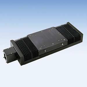
15 Maintenance 120 Series Belt Drive Positioning Table LINTECH's 120 series positioning table uses a belt & pulley drive system instead of a screw & nut system. This provides the user with a few different installation and maintenance considerations. Lubrication of the linear rails should follow the recommendations on pages of this service manual. The polyurethane belt with reinforced high strength steel members is adjusted by LINTECH for proper tension prior to shipment. Under normal and proper use, the belt tension need not be adjusted. However, if field adjustment is required because of belt stretching, the self-locking belt tension adjustment screw shown below, quickly modifies belt tension with just a partial turn. WARNING - putting "too much" tension on the belt can cause permanent stretching and tearing of the belt. Therefore be careful when adjusting belt tension. A general rule of thumb is that when you press down on the top belt - there should be some deflection - DO NOT try to eliminate all the deflection. WARNING - LINTECH is not responsible for improper field adjustments of belt tension. Another installation item to be concerned about is the maximum input torque to the 120 series positioning table drive shaft. The maximum input torque to any belt drive positioning table is limited by the belt & pulley system and is speed dependent. WARNING - Exceeding any of these values, by either a directly coupled motor or from the output of a gearhead & motor system, can deform or shear a belt tooth, and/or cause the belt to slip over pulley teeth during motion. Refer to the Positioning Systems catalog for maximum input torque to the 120 series table. 120 Series Belt Tension Adjustment: Important Note: Only a partial turn of the self-locking screw is required for increasing, or decreasing, the tension on the belt. DO NOT try to eliminate all belt deflection. Step 1: Remove the attached motor/gearhead from the table and take a Breakaway torque reading with a torque wrench. If the reading is between 45 to 60 oz-in : NO adjustment is required. Otherwise, locate the Belt Tension Screw. Step 2: Take breakaway torque readings with the torque wrench after each 1/4 clockwise turn of the Belt Tension Screw. Stop turning the Belt Tension Screw once the breakaway torque reading is between 45 to 60 ozin. The belt tension is now adjusted correctly for proper table operation. DO NOT exceed 100 oz-in of breakaway torque. Belt Tension Screw Adjustment 120 Series Gearheads: Version 1 The gearhead, with correct coupling, will be pre-mounted to the 120 series table if the gearhead was purchased from LINTECH. LINTECH offers 2 different versions of gearheads. Version 1 has 4 nut & bolt sets, and an easy to mount motor clamp-on pinion. The included gearhead drawing shows the exact mounting location on the motor shaft for the clamp-on pinion. WARNING - This location is critical for proper operation & life of the gearhead - care should be taken when mounting the motor to the gearhead. Version 2 has an integral coupling for the motor shaft. Four nut & bolt sets are provided to mount the motor. Motor Clamp-on Pinion (needs to be precisely located on motor shaft for proper gearhead operation) Motor adapter bracket (if required) Version 2 Gearhead Coupling 120 series Motor Sleeve Motor adapter bracket Gearhead Coupling 120 series 13
16 Installation 180 Series Belt Drive Positioning Table LINTECH's 180 series positioning table uses a belt & pulley drive system instead of a screw & nut system. This provides the user with a few different installation and maintenance considerations. Lubrication of the linear rails should follow the recommendations on pages of this service manual. The polyurethane belt with reinforced high strength steel members is adjusted by LINTECH for proper tension prior to shipment. Under normal and proper use, the belt tension need not be adjusted. However, if field adjustment is required because of belt stretching, the self-locking belt tension adjustment screw shown below, quickly modifies belt tension with just a partial turn. WARNING - putting "too much" tension on the belt can cause permanent stretching and tearing of the belt. Therefore be careful when adjusting belt tension. A general rule of thumb is that when you press down on the top belt - there should be some deflection - DO NOT try to eliminate all the deflection. WARNING - LINTECH is not responsible for improper field adjustments of belt tension. Another installation item to be concerned about is the maximum input torque to the 180 series positioning table drive shaft. The maximum input torque to any belt drive positioning table is limited by the belt & pulley system and is speed dependent. WARNING - Exceeding any of these values, by either a directly coupled motor or from the output of a gearhead & motor system, can deform or shear a belt tooth, and/or cause the belt to slip over pulley teeth during motion. Refer to the Positioning Systems catalog for maximum input torque to the 180 series table. 180 Series Belt Tension Adjustment: Important Note: Only a partial turn of the self-locking screw is required for increasing, or decreasing, the tension on the belt. DO NOT try to eliminate all belt deflection. Step 1: Remove the attached motor/gearhead from the table and take a Breakaway torque reading with a torque wrench. If the reading is between 45 to 60 oz-in : NO adjustment is required. Otherwise, locate the Belt Tension Screw. Step 2: Take breakaway torque readings with the torque wrench after each 1/4 clockwise turn of the Belt Tension Screw. Stop turning the Belt Tension Screw once the breakaway torque reading is between 45 to 60 oz-in. The belt tension is now adjusted correctly for proper table operation. DO NOT exceed 100 oz-in of breakaway torque. Belt Tension Screw Adjustment 180 Series Gearheads: The gearhead, with correct coupling, will be pre-mounted to the 180 series table if the gearhead was purchased from LINTECH. The gearhead has an integral coupling for the motor shaft. Four nut & bolt sets are provided to mount the motor. Motor Sleeve Motor adapter bracket Gearhead Coupling 180 series 14
17 Installation 550 Series Belt Drive Positioning Table LINTECH's 550 series positioning table uses a belt & pulley drive system instead of a screw & nut system. This provides the user with a few different installation and maintenance considerations. Lubrication of the linear rails should follow the recommendations on pages of this service manual. The polyurethane belt with reinforced high strength steel members is adjusted by LINTECH for proper tension prior to shipment. Under normal and proper use, the belt tension need not be adjusted. However, if field adjustment is required because of belt stretching, the self-locking belt tension adjustment screws shown below, quickly modify belt tension with just a partial turn of each. WARNING - putting "too much" tension on the belt can cause permanent stretching and tearing of the belt. Therefore be careful when adjusting belt tension. WARNING - LINTECH is not responsible for improper field adjustments of belt tension. Another installation item to be concerned about is the maximum input torque to the 550 series positioning table drive shaft. The maximum input torque to any belt drive positioning table is limited by the belt & pulley system and is speed dependent. WARNING - Exceeding any of these values, by either a directly coupled motor or from the output of a gearhead & motor system, can deform or shear a belt tooth, and/or cause the belt to slip over pulley teeth during motion. Refer to the Positioning Systems catalog for maximum input torque to the 550 series table. 550 Series Belt Tension Adjustment: Important Note: The 4 Set Screws lock into place 2 Belt Tension Screws. The 4 Set Screws must first be loosened before the 2 Belt Tension Screws can be adjusted. Only a partial turn of the 2 Belt Tension Screws is required for increasing, or decreasing, the tension on the belt. DO NOT over tension the belt. Step 1: Remove the attached motor/gearhead from the table and take a Breakaway torque reading with a torque wrench. If the reading is close to 16 in-lbs : NO adjustment is required. Otherwise, locate the Belt Tension Screws by removing the "Window Cover Plate (held in place with 4 screws)" which is located on the 550 table end opposite the motor mount. Step 2: Loosen the 4 set screws that lock the 2 Belt Tension Screws in place. Take Breakaway torque readings with the torque wrench after each 1/2 clockwise turn of both Belt Tension Screws. Stop turning the Belt Tension Screws once the Breakaway torque reading is between 12 to 16 in-lbs. DO NOT exceed 25 in-lbs of Breakaway torque. Step 3: Once the desired Breakaway torque is reached, manually move the table carriage to the motor mount end and observe through the "Belt Tracking Window" how the belt tracks against the belt return pulley. Then manually move the table carriage to the opposite end of travel and observe how the belt tracks against the belt return pulley. The belt will move side to side on the belt return pulley - but the belt should never run up on the sides of the belt return pulley. Small, 1/8 turns of either "Belt Tension Screw" may need to be made to keep the belt centered on the belt return pulley. The belt tension is now adjusted correctly for proper table operation. Step 4: Tighten the 4 set screws that lock the 2 Belt Tension Screws in place, remount the "Window Cover Plate', and fill the 4 counter bored holes that hold the "Window Cover Plate" in place with RTV or equivalent. Set Screws Window Cover Plate and 4 Cover Plate Screws with RTV Belt Tracking Window Belt Tension Screw Adjustment 550 Series Gearheads: The gearhead, with correct coupling, will be pre-mounted to the 550 series table if the gearhead was purchased from LINTECH. The gearhead has an integral coupling for the motor shaft. Four nut & bolt sets are provided to mount the motor. Motor Sleeve Motor adapter bracket Gearhead Coupling 550 series 15
18 Table Options Motor Couplings LINTECH provides three different types of couplings that can be used to mount a motor to a positioning table. These couplings compensate for misalignment between the motor shaft & screw (or belt) drive shaft extension. This provides for trouble-free operation as long as certain precautions are taken. The connected motor output torque should never exceed the coupling maximum torque capacity. These couplings are not limited by speed, but can be damaged if a move profile has large acceleration rates or is constantly "SLAMMED" into a mechanical hard stop. Large inertia loads with quick acceleration and deceleration rates could also have the damaging effects to a coupling by weakening it over time. Couplings with larger torque capacity may be required for high accelerations, large back driving vertical loads, high torque output motors or gear boxes, etc.. One common cause for coupling failure is from the user not connecting the EOT switches to a position controller. This situation can result in the carriage over traveling the EOT switches to the point where the carriage collides with the positioning table end plates. The sudden mechanical stop between the carriage & the end plates fatigues the coupling, which can cause coupling failure. This also can destroy mechanical end of travel switches, and the lead screw nut, or belt & pulley, assembly. Therefore, it is not a good practice to use any positioning table's end plates as a mechanical hard stop. Another cause of coupling failure can occur during the tuning of a servo system that is attached to the positioning table. When servo gains are first adjusted, violent oscillations can occur, which can fatigue, or damage, a coupling. Care should be taken to limit these wild oscillations, by either tuning the servo system before coupling the motor to the table, or by limiting the current in the servo drive during the tuning process. Motor Adapter Brackets - Another important area of coupling concern is in cases where a non- LINTECH motor adapter bracket is being installed by the user to a positioning table. In some cases, the added bracket thickness along with a potentially short motor shaft extension, can cause the LINTECH supplied coupling to be too short to "clamp" onto the motor shaft. If such a situation arises, a different coupling with a longer length may be required. See page 17 for a list of standard LINTECH couplings. Custom couplings will require factory contact to determine torque capacity. Positioning Table Series Shaft extension diameter at motor mount end inches (mm) NEMA 23 Motor Bracket Diameter Length inches (mm) Maximum Allowable Coupling Dimensions for use with inches (mm) NEMA 34 Motor Bracket Diameter Length inches (mm) inches (mm) NEMA 42 Motor Bracket Diameter Length inches (mm) inches (mm) 90 and (9,53) (38,10) (53,34) (38,10) (66,04) N.A. N.A. 100, 110 and (7,92) (38,10) (44,45) (38,10) (57,15) N.A. N.A. 120 and (9,53) (38,10) (48,26) (50,80) (60,32) N.A. N.A. 160 and (9,53) (38,10) (44,45) (38,10) (57,15) N.A. N.A (12,70) (38,10) (53,34) (38,10) (66,04) (50,80) (63,50) (19,87) N.A. N.A (50,80) (63,50) (50,80) (63,50) (18,00) N.A. N.A (58,42) (78,74) (58,42) (78,74) (4,75) (21,60) (38,10) (21,60) (38,10) N.A. N.A. N.A. - Not Available 16
19 Table Options C Type - Helical-Cut Clamp Style Design (Aluminum) L Motor Couplings H Type - 3 Member Clamp Style Design (Aluminum Hubs with Acetal Disc) L G Type - Low Wind-up, High Torque Clamp Style Design (Aluminum Hubs with Stainless Steel Bellows) L D Bore Bore D Bore Bore D Bore Bore Model # D L Bore Diameters inches inches Table Motor Minimum (mm) (mm) (in) (mm) Maximum (in) (mm) Weight ounces (grams) Inertia oz-in 2 (g-cm 2 ) Wind-up arc-sec/oz-in (deg/n-m) Max Torque oz-in (N-m) C075--aaa 0.75 (19,1) 1.00 (25,4) aaa (23) 0.06 (10) 45.0 (1,8) 200 (1,4) C100--aaa 1.00 (25,4) 1.50 (38,1) aaa (43).19 (35) 23.0 (0,9) 400 (2,8) C125--aaa 1.25 (31,8) 2.00 (50,8) aaa (99).68 (124) 15.0 (0,59) 700 (4,9) C150--aaa 1.50 (38,1) 2.37 (60,2) aaa (156) 1.54 (282) 13.0 (0,51) 950 (6,7) H075--aaa 0.75 (19,1) 1.02 (25,9) aaa (14) 0.04 (6) 12.6 (0,50) 225 (1,5) H100--aaa 1.00 (25,4) 1.28 (32,5) aaa (34).15 (27) 7.2 (0,28) 450 (2,8) H131--aaa 1.31 (33,3) 1.89 (48,0) aaa (82).62 (114) 2.5 (0,098) 1,000 (7,1) H163--aaa 1.63 (41.4) 2.00 (50,8) aaa (153) 1.79 (328) 1.2 (0,047) 2,000 (14,1) H197--aaa 1.97 (50,0) 2.35 (59,7) aaa (215) 3.69 (674) 1.1 (0,043) 3,600 (25,4) H225--aaa 2.25 (57,2) 3.07 (78,0) aaa (371) 8.29 (1516) 0.6 (0,024) 5,300 (37,4) G075--aaa 0.79 (20,0) 1.02 (26,0) aaa (22) 0.06 (11) 2.0 (0,079) 300 (2,1) G100--aaa 0.99 (25,2) 1.26 (32,0) aaa (36).16 (29) 1.0 (0,39) 500 (3,5) G126--aaa 1.26 (32,1) 1.62 (41,0) aaa (74).54 (99) 0.3 (0,012) 1,100 (7,7) G158--aaa 1.58 (40.2) 1.85 (47,0) aaa (120) 1.34 (245) 0.2 (0,008) 2,400 (17,0) G177--aaa 1.77 (45,0) 2.48 (63,0) aaa (200) 2.78 (508) 0.2 (0,008) 4,250 (30,0) G220--aaa 2.20 (56,0) 2.56 (65,0) aaa (300) 6.41 (1172) 0.04 (0,002) 7,100 (50,0) G260--aaa 2.60 (66,0) 3.07 (78,0) aaa (600) (3276) 0.03 (0,001) 9,600 (68,0) Possible values for & aaa inch inch inch inch inch inch mm mm mm mm mm mm mm mm mm mm mm 17
20 Table Options Linear & Rotary Incremental Encoders Linear Encoders: If a linear encoder is supplied by LINTECH, it comes mounted & aligned to the positioning table. This encoder operates via an LED pickup of an etched strip on a glass spar which spans the entire length of the encoder. WARNING - It is important NOT to make any adjustments to the encoder mounting. The encoder alignment is extremely critical and is important for proper accuracy, repeatability, and performance. The warranty is voided if adjustments are made to any part of the encoder or encoder mounting. Rotary Encoders: If a rotary encoder is supplied by LINTECH, it comes installed on the table opposite the motor mount end. This rotary encoder is shaftless and is physically mounted to the screw shaft or drive shaft extension on a belt drive table. WARNING - It is important NOT to remove the rotary encoder from the positioning table. The glass disk is pre-aligned by LINTECH for proper operation. Removing the encoder could effect its performance. The encoder is protected with a sheet metal cover, which is not totally sealed. Therefore if splashing fluid, or other materials is present, precautions should be made to redirect these items away from the encoder housing since contaminants which penetrate the housing can cause encoder failure. Linear Encoder - Screw Driven Tables 10 foot (3 m) shielded cable, with 12 pin DIN connector; (mating DIN connector provided) Note: The encoder read head is mounted to the table carriage with the encoder lip seal facing down. Notes: When using a linear encoder, the user can either use the mating connector which interfaces to the connector on the linear encoder, or just cut the connector that is on the encoder and use the wire chart on page 19 for wire color information. Rotary Encoder - Screw Driven Tables Rotary Encoder - Belt Driven Tables Encoder Protective Cover 10 foot (3 m) shielded cable with flying leads 10 foot (3 m) shielded cable with flying leads Encoder Protective Cover 18
21 Table Options Linear & Rotary Incremental Encoders Specification E01 or RE-500 ROTARY ENCODERS E02 or RE-1000 E03 or RE-1270 E10 or LE series LINEAR ENCODERS E11 Line Count 500 lines/rev 1000 lines/rev Pre Quadrature Resolution revs/pulse revs/pulse Post Quadrature Resolution revs/pulse 0,00025 revs/pulse Accuracy 1270 lines/rev revs/pulse revs/pulse 2500 lines/inch 125 lines/mm inch/pulse 8 microns/pulse inch/pulse 2 micron/pulse +/ in/40" +/- 5 microns/m Maximum Speed 50 revs/sec 79 inches/sec 2 m/sec Maximum Accel 40 revs/sec ft/sec 2 40 m/sec 2 Excitation Power ma ma Operating Temperature 32 0 F to F (0 0 C to 60 0 C) 32 0 F to F (0 0 C to 50 0 C) Humidity 20% to 80% non condensing 20% to 80% non condensing Shock 10 G's for 11 msec duration 15 G's for 8 msec duration Weight 0.7 lbs (0,283 kg) 0.7 oz/inch (0,00078 kg/mm) length of scale lbs (0,23 kg) read head and brackets Cable Length 10 ft (3 m), unterminated 26 gauge leads 10 ft (3 m) with DIN connector Zero Reference Output Once per revolution At center of encoder length Outputs TTL square wave; Two channel (A+ & B+); Differential (A- & B-); Line Driver LINEAR Din Pin # Wire Color C Green D Yellow E Pink L Red ROTARY Wire Color White Blue Green Orange Description Channel A+ (or A) Channel A- (or A) Channel B+ (or B) Channel B- (or B) Notes: 1. Both linear & rotary encoders are not totally sealed, and precautions should be taken to protect the encoder in corrosive or fluid splashing type of environments. G H A B K Brown Grey Shield White Black White/Black Red/Black Black Red Channel Z+ (or Z) Channel Z- (or Z) Case ground Common + 5 vdc (+/- 5%) 2. DO NOT remove linear or rotary encoders. Their mounting orientation is critical for proper operation. Encoders are adjusted by LINTECH, prior to shipping, for proper operation. 19
22 Table Options Power-Off Electric Brakes - Operation & Interface This mechanical brake is primarily used in vertical ball screw (or belt drive) applications. Since a ball screw, and belt drive, are very efficient drive mechanisms, they will allow the positioning table's carriage/load to backdrive when motor power is off (for most applications). Thus, if a power-off electric brake is used, and properly interfaced with a position controller, it will hold the carriage in-place whenever motor power is off, or in case of a power failure. The brake is a "friction type" and is mounted to the screw (or belt drive) shaft extension on the end plate opposite the motor mount end. When power is applied to the brake, the brake is opened or "released". When power is removed, the brake is activated which prevents the carriage from moving, so long as the brake holding torque is greater than the backdriving force of the screw (or belt drive) with the attached load. The brake comes with two wires for power (24 or 90 VDC). These should be wired directly to an external power supply, or user supplied relay network. In most cases, your motor drive and brake power should come from the same source. Thus, when the drive loses power, so will the brake. For stepper & servo systems, further interfacing is required to ensure power-off braking if a motor stalls or there is a drive fault. This requires an encoder to be interfaced to a position controller which will activate relays to remove brake power when a fault occurs. Below is a block diagram of a recommended interface. See the Positioning Systems catalog for further brake specifications. Brakes Table Series Brake Model Number Holding Force in-lbs (N-m) Excitation Voltage volts Current amps Weight lbs (kgf) 90, 100, 110, 120, 130, 150, 160, 170 and B01 or BR-1-A 24 VDC (2,0) 18 B02 or BR-1-B 90 VDC (2,0) 1.4 (0,62) 1.4 (0,62) 200 B03 or BR-2-A 84 (9,49) 24 VDC B04 or BR-2-B 90 VDC (949) 2.1 (0,95) 2.1 (0,95) 250 and B05 or BR-3-A 24 VDC (20,3) 180 B06 or BR-3-B 90 VDC (20,3) 2.8 (1,27) 2.8 (1,27) Power Supplies Model Number volts DC Output amps style volts AC Input amps Hz regulated 120 / / regulated unregulated 120 / / / unregulated /60 Note: The brake MUST NOT be engaged when the positioning table is in motion. Moving the table with the brake applied could damage the brake and the positioning table. Also, continuous use of the brake to stop a table (and load) that is in motion, could damage the brake. 20 Input Voltages Position Controller Fault Output Signal Drive or Amplifier Relay Brake Power Supply Encoder Motor Positioning Table Brake
23 Table Options Switches - Mechanical, Magnetic Reed, Hall Effect, & Proximity LINTECH provides two EOT (end of travel) switches and one HOME switch for each table (when ordered). The EOT switches will give a signal to the motor controller to stop motion immediately when activated (they protect the carriage from colliding with the table end plates). This protects the positioning table from mechanical damage, protects operating personnel from injury, and prevents the user mounted load from striking other components within the area. The home switch is placed just forward from the end of travel switch located at the motor mount end. This switch is used by the position controller as a known fixed mechanical location on the positioning table. It serves to synchronize the position controller with the positioning table electronically. LINTECH can provide either mechanical or non-contact switches. See pages of this for detailed information on the different switches. The below diagrams show the general location of each switch. Depending on the table series, or custom system, the switches could be located "inside" or "outside" the positioning system. It is highly recommended that any positioning table (standard or custom) used with a position controller, should have "END of TRAVEL" switches installed (and operating properly) for protection of personnel, table carriage, and user mounted load. Switch Locations (these are the normal locations - depends on table series and customer preference) 90, 150, 200 & 250 series 130, 160, 170, 180 & 550 series CW EOT CCW EOT Shielded Cable CW EOT Cam CCW EOT Home Shielded Cable Home CW EOT 100, 110, & 120 series CCW EOT Shielded Cable Home NOTES: 1. EOT switches are normally located inward from a positioning table's maximum travel hard stops. Thus, reducing the overall system travel from the listed table's travel lengths. 2. The CW and CCW switches are usually wired normally closed so the position controller can detect a broken wire. 3. When using the motor wrap option with any table, the CW & CCW designations should be reversed at the cable end for proper operation. CW - Clockwise CCW EOT NC NO - Counter Clockwise - End of Travel - Normally Closed - Normally Open Switch location adjustments - depending on the table series, or custom positioning system, each switch is usually mounted to a bracket which in turn is mounted to the table base. The switch activation cam is either mounted to the lead screw nut assembly or the table carriage. The activation cam may have a magnet attached to it - depends on what type of switch is being used. 90, 150, 200 & 250 series - The switch mounting bracket usually has slotted mounting holes which allow approximately 0.75 inches of movement for the individual switch on the table base. 100, 110, 120, 130, 160, 170, 180 & 550 series - The switch mounting bracket "snaps" into a T-slot that runs along the entire length of the table base. This allows the user to locate each switch anywhere on the positioning table. For the 100, 110, 120 & 130 series remove the mounting bracket by using a screw driver to "pry" out the bracket from one end - be careful not to damage the wires that run inside the T-slot. Reinsert the mounting bracket by placing the bottom of the bracket in the T-slot first & then "snapping" the top of the bracket in place. For the 160, 170, 180 & 550 series remove the mounting bracket by loosening the set screws that lock the bracket in the T-slot. 21
24 Table Options EOT & Home Switch Wiring - Mechanical & Reed Mechanical Switches: Non-Contact Reed Switches: Repeatability : +/ inch (5 microns) Repeatability : +/ inch (50 microns) Electrical : VAC 1 85 VDC Electrical : VAC VDC Activation Style : mechanical cam Activation Style : magnetic Activation Area : depends on table series from 0.5 inches (12,7 mm) to 1.75 inches (44,45 mm) of travel Activation Area : 0.30 inches (7,62 mm) of travel Temperature Range : - 25 o C to + 85 o C Temperature Range : - 10 o C to + 60 o C Environment : non wash down Environment : non wash down Individual Switch Wiring : none Individual Switch Wiring : 12 inch (305 mm) leads Each Switch NO Switch NC Switch NC C NO (red) NC NO C C Standard LINTECH Wiring : from table end plate, 10 foot (3 m) shielded cable, 6 conductor, 24 AWG, unterminated leads Standard LINTECH Wiring : from table end plate, 10 foot (3 m) shielded cable, 6 conductor, 24 AWG, unterminated leads Wire Color Description Wire Color Description Black Blue CW EOT CW Common NC Black Blue CW EOT CW Common NC Red White CCW EOT CCW Common NC Red White CCW EOT CCW Common NC Brown Green HOME HOME Common NO Brown Green (red) HOME HOME Common NO Silver Shield Silver Shield CW CCW EOT NC NO - Clockwise - Counter Clockwise - End of Travel - Normally Closed - Normally Open CW - Clockwise CCW - Counter Clockwise EOT - End of Travel NC - Normally Closed NO - Normally Open NC switch - red dot marker NO switch - green dot marker 22
25 Table Options EOT & Home Switch Wiring - Hall Effect & Proximity Non-Contact Hall Effect Switches: Non-Contact Proximity Switches - "CE": Repeatability : +/ inch (5 microns) Repeatability : +/ inch (5 microns) Electrical : 5-24 VDC 15 ma - power input 25 ma max - signal Electrical : VDC 15 ma - power input 100 ma max - signal Actuation Style : magnetic Actuation Style : non-magnetic cam Activation Area : 0.32 inches (8,13 mm) of travel Activation Area : depends on table series from 0.5 inches (12,7 mm) to 1.75 inches (44,45 mm) of travel Temperature Range : - 10 o C to + 60 o C Temperature Range : - 25 o C to + 75 o C Environment : wash down Environment : IEC IP67 wash down Individual Switch Wiring : 12 inch (305 mm) leads Individual Switch Wiring : 6.5 foot (2 m) cable for NPN : 3.3 foot (1 m) cable for PNP NPN wiring connection - both NC & NO NPN Switch Sinking Power - (Brown) Signal - (Black) Common - (Blue) Load 5-24 VDC NPN Switch Sinking PNP Switch Sourcing NPN wiring connection - both NC & NO Power - (Brown) Signal - (Black) Common - (Blue) Load PNP wiring connection - both NC & NO Power - (Brown) Signal - (Black) Common - (Blue) Load VDC VDC Standard LINTECH Wiring : from table end plate, 10 foot (3 m) shielded cable; 9 conductor, 24 AWG, unterminated leads Standard LINTECH Wiring : from table end plate, 10 foot (3 m) shielded cable; 9 conductor, 24 AWG, unterminated leads Wire Color Brown Black Blue CW Power CW EOT CW Common Description (brown) (blue) switch NC Wire Color Brown Black Blue CW Power CW EOT CW Common Description (brown) (blue) switch NC Red White Green Orange Yellow Grey CCW Power CCW EOT CCW Common Home Power Home Home Common (brown) (blue) (brown) (blue) switch switch NC NO Red White Green Orange Yellow Grey CCW Power CCW EOT CCW Common Home Power Home Home Common (brown) (blue) (brown) (blue) switch switch NC NO Silver Shield Silver Shield CW - Clockwise CCW - Counter Clockwise EOT - End of Travel NC - Normally Closed NO - Normally Open CW CCW EOT NC NO - Clockwise - Counter Clockwise - End of Travel - Normally Closed - Normally Open NC switch - red dot marker NO switch - green dot marker NC switch - red dot marker NO switch - green dot marker 23
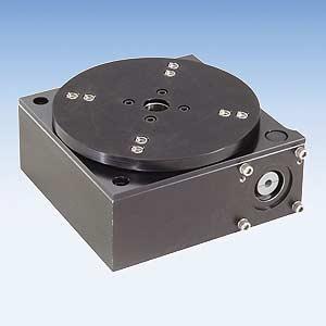
26 Installation 300 Series Rotary Positioning Table LINTECH's 300 series rotary positioning table uses a low backlash precision worm gear drive system and is designed for light industrial applications. The user mounting surface needs to be flat to (0.001 in/ft) in order to achieve the published operating specifications of the 300 series. The circular table top can be removed for modification if desired. The base section houses the rotary bearing elements and should under no circumstances be disassembled. Modifying or dismantling the base section will VOID the warranty of any 300 series positioning table. Customer adapter plates should not be 50% greater than the table top diameter (example: table top diameter 8" - max customer adapter plate 12"). Care should be taken when mounting additional items to a customer adapter plate. Heavy items need to be precisely balanced on the adapter plate so as to not introduce additional dynamic forces to the table when moving. Exceeding recommended load capacity can permanently damage a 300 series table. The plastic cover on the side of the base section can be removed for mounting of a user supplied motor. The cover should be replaced as it protects the motor coupling area from external contaminates. Use a Lincoln needle fitting #5803, or equivalent, on the external grease fitting which is located on the base section. Use only #2 LITHIUM grease as a lubricant. Lubricate on a regular basis but DO NOT over lubricate. Non-Contact Reed Switches Repeatability Electrical Activation Style Activation Area Temperature Range Environment Individual Switch Wiring : +/- 100 arc-sec : VAC VDC : magnetic : 0.30 inches (7,62 mm) of travel : - 10 o C to + 60 o C : non wash down : 12 inch (305 mm) leads NO Switch Non-Contact Hall Effect Switches Repeatability Electrical Actuation Style Activation Area Temperature Range Environment Individual Switch Wiring : +/- 10 arc-sec : 5-24 VDC 15 ma - power input 25 ma max - signal : magnetic : 0.32 inches (8,13 mm) of travel : - 10 o C to + 60 o C : wash down : 12 inch (305 mm) leads NPN wiring connection - NO NO (red) C NPN Switch Sinking Power - (Brown) Signal - (Black) Common - (Blue) Load 5-24 VDC Standard LINTECH Wiring (provided when switch option is ordered with any table) : from table, 10 foot (3 m) shielded cable, 6 conductor, 24 AWG, unterminated leads Standard LINTECH Wiring (provided when switch option is ordered with any table) : from table, 10 foot (3 m) shielded cable; 9 conductor, 24 AWG, unterminated leads Pin # Wire Color Description Pin # Wire Color Description Brown Green Silver HOME HOME Common Shield (red) NO Orange Yellow Grey Silver Home Power Home Home Common Shield (brown) (blue) switch NO 9 pin connector, with 10 foot (3 m) shielded cable 24
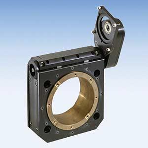
27 Installation 400 Series Rotary Positioning Table LINTECH's 400 series rotary positioning table uses a low backlash precision bronze and steel worm gear drive system and is designed for heavier duty industrial applications. The rigid pair of 4 point contact radial ball bearings will produce smooth table top rotation. The motor adapter bracket can only accommodate a NEMA 34 size step motor or servo motor with either a 3/8" or 1/2" diameter shaft. The adapter bracket has a bushing which requires a #304 Woodruff key installed on the motor shaft for proper coupling. The motor adapter bracket is coupled to the worm gear drive using a belt & pulley system. The adapter bracket can be mounted on either side of the belt & pulley system by changing the NEMA 34 bracket from one side to the other. The belt & pulley system can be mounted to two different sides of the rotary table base and also can be rotated around its connection point to the table base. This arrangement allows the user to locate their motor in a number of different orientations. To change the NEMA 34 bracket on the belt & pulley system from one side of "B" to the other: 1) Remove the 2 "C" Flat Head socket cap screws on the belt & pulley system below. 2) Locate and mount the NEMA 34 bracket to the other side of the belt & pulley system. To rotate the belt & pulley system around side "B" below: 1) Loosen the "D" Socket Head cap screw on the table (located on the drawings below). 2) The belt & pulley system will now rotate around side "B". 3) Retighten the "D" Socket Head cap screw after locating the belt & pulley position. To locate the belt & pulley system from side "B" to side "A" below: 1) Loosen the "D" Socket Head cap screws on the table (located on the drawings below). 2) Remove the belt & pulley system by lightly tapping with a rubber hammer. 3) Locate the belt & pulley system to side "A" and retighten the "D" Socket Head cap screws. Lubrication - No lubrication of the worm gear drive or belt & pulley system is required. Side "A" (C) Flat Head Socket Cap Screws Side "B" NEMA 34 Motor Adapter Bracket (D) Socket Head Cap Screws Belt & Pulley Drive System 3/8" or 1/2" diameter bushing with keyway. Requires #304 Woodruff key be installed on motor shaft. (8) #10-24 Inserts for Load Mounting Mechanical HOME Switch Cam Shielded Cable Mechanical Switch Repeatability Electrical : +/- 10 arc-sec : VAC 1 85 VDC Wire Color Brown Green Silver Description HOME HOME Common Shield NO Standard LINTECH Wiring (provided when switch option is ordered with any table) Activation Style Activation Area Temperature Range Environment Individual Switch Wiring : mechanical cam : 0.5 inches (12,7 mm) of travel : - 25 o C to + 85 o C : non wash down : none Each Switch NC C NO : from table, 10 foot (3 m) shielded cable, 6 conductor, 24 AWG, unterminated leads 25
 different models to choose from with load capacities from 25 pounds (11 kg) to 16,600 pounds (7530 kg). Some models have over 46 different screw drive options.")


28 Positioning Systems 340 page catalog details round & square rail linear positioning tables that are either screw or belt driven. Twelve (12) different models to choose from with load capacities from 25 pounds (11 kg) to 16,600 pounds (7530 kg). Some models have over 46 different screw drive options. Also, two (2) different worm gear driven rotary tables to choose from. Ball Screw Assemblies LINTECH provides three different types of ball screw assemblies - rolled, precision rolled and precision ground ball screws. From to inch, and 16 to 20 mm diameters, with lengths to 138 inches (3500 mm). English & Metric leads available. Simple, Fixed and Rigid supports in various combinations. Positioning Components LINTECH shaft assembly products provide solutions to many linear motion applications. Single and TWIN RAIL shaft assemblies are provided from to 2.00 inch (12 to 50mm) diameters, in lengths up to 192 inches (4875 mm). TWIN RAIL carriage assemblies easily adapt to the TWIN RAIL shaft assemblies for a complete transport system. LINTECH YOUR LOCAL AUTOMATION SPECIALIST: 1845 Enterprise Way Monrovia, CA (800) (626) Fax: (626) Web Site: lintech@lintechmotion.com
LINTECH.
 Welcome to Our local technical support group consists of Automation Specialists located throughout the World. These Automation Specialists are experienced in the use of electronic and mechanical motion
300 & 400 Series Positioning Tables
 300 & 400 Series Positioning Tables 300 Series Introduction L-2 400 Series Introduction L-3 Specifications L-5 300 Series Dimensions L-6 400 Series Dimensions L-7 300 Series Motor Couplings L-8 300 Series
Design Considerations
 Design Consideration RS Series PS Series GS Series * Rolled Ball Screw * Tapped Ball Nut * English Leads * English Diameters * Pre-loaded & Non-preloaded Nuts * Simple, Fixed and Rigid Housings * Available
PO Box 645, Stockton, Missouri, FAX superiorgearbox.com
 I000-7000-D0447-A 4/7/05 1 SAFETY PRECAUTIONS CAUTION Please read this entire document prior to operating the gear drive. Gear drive failure and / or injury to operators may be caused by improper installation,
PO Box 645, Stockton, Missouri, FAX superiorgearbox.com W D0446-A 4/1/05 1
 W000-7000-D0446-A 4/1/05 1 SAFETY PRECAUTIONS CAUTION Please read this entire document prior to operating the gear drive. Gear drive failure and / or injury to operators may be caused by improper installation,
using Class 2-C (Centralizing) tolerances. Jack lift shaft lead tolerance is approximately 0.004" per foot.
 tolerances. Jack lift shaft lead tolerance is approximately 0.004 per foot.") WORM GEAR JACK MODELS WORM GEAR ACTIONJAC JACKS Jack systems are ruggedly designed and produced in standard models with load handling capacities from 1/4 ton to 100 tons. They may be used individually
WORM GEAR JACK MODELS WORM GEAR ACTIONJAC JACKS Jack systems are ruggedly designed and produced in standard models with load handling capacities from 1/4 ton to 100 tons. They may be used individually
LINTECH. Welcome to LINTECH
 Welcome to Our local technical support group consists of Automation Specialists located throughout the World. These Automation Specialists are experienced in the use of electronic and mechanical motion
Electric Actuator Installation, Operation & Maintenance Manual
 ICI Indelac Controls, Inc. Electric Actuator Installation, Operation & Maintenance Manual 6810 Powerline dr.-florence, Ky. 41042 - Telephone 859-727-7890, Tool free 800-662-9424 Fax. 859-727-4070, e-mail:
Worm Gear Reducers Installation, Lubrication and Maintenance Instructions
 Selection Information Read ALL instructions prior to operating reducer. Injury to personnel or reducer failure may be caused by improper installation, maintenance or operation. Written authorization from
TECHNICAL INFORMATION
 General Nomenclature Spherical Roller Bearings The spherical roller bearing is a combination radial and thrust bearing designed for taking misalignment under load When loads are heavy, alignment of housings
OVERLOAD CLUTCHES FOR INDEX DRIVES
 The Driving Force in Automation OVERLOAD CLUTCHES FOR INDEX DRIVES WARNING WARNING This is a controlled document. It is your responsibility to deliver this information to the end user of the CAMCO indexer.
Linear Actuator with Toothed Belt Series OSP-E..B
 Linear Actuator with Toothed Belt Series OSP-E..B Contents Description Data Sheet No. Page Overview 1.20.001E 21-24 Technical Data 1.20.002E-1 to 5 25-29 Dimensions 1.20.002E-6 30 Order Instructions 1.20.002E-7
Heavy Duty Ball Screw Linear Actuators
 Heavy Duty Ball Screw Linear Actuators Thrust From 2,000 to 25,000 lbf Heavy Wall Steel Construction Longest Life Simultaneous High Thrust with High Speed Piston with Rugged Anti Rotation Feature Sealed
Precision Modules PSK
 Precision Modules PSK 2 Bosch Rexroth AG Precision Modules PSK R999000500 (2015-12) Identification system for short product names Short product name Example:: P S K - 050 - N N - 1 System = Precision Module
Precision Modules PSK
 Precision Modules PSK The Drive & Control Company Rexroth Linear Motion Technology Ball Rail Systems Roller Rail Systems Standard Ball Rail Systems Super Ball Rail Systems Ball Rail Systems with Aluminum
Standard Positioning Components
 LINTECH Standard Positioning Components Precision Shafting LINTECH's precision "cut to length" 1060 carbon steel inch precision shafting is manufactured with the highest standards for surface finish, surface
TRANSLATION (OR LINEAR)
") 5) Load Bearing Mechanisms Load bearing mechanisms are the structural backbone of any linear / rotary motion system, and are a critical consideration. This section will introduce most of the more common
5) Load Bearing Mechanisms Load bearing mechanisms are the structural backbone of any linear / rotary motion system, and are a critical consideration. This section will introduce most of the more common
Compact Modules. with ball screw drive and toothed belt drive R310EN 2602 ( ) The Drive & Control Company
 The Drive & Control Company") with ball screw drive and toothed belt drive R310EN 2602 (2007.02) The Drive & Control Company Bosch Rexroth AG Linear Motion and Assembly Technologies Ball Rail Systems Roller Rail Systems Linear Bushings
with ball screw drive and toothed belt drive R310EN 2602 (2007.02) The Drive & Control Company Bosch Rexroth AG Linear Motion and Assembly Technologies Ball Rail Systems Roller Rail Systems Linear Bushings
Now you can get design flexibility and lasting performance from our complete family of AccuDrive Precision Products.
 ACCUDRIVE PRECISION PRODUCTS Now you can get design flexibility and lasting performance from our complete family of AccuDrive Precision Products. Series W Precision Servo Gearhead Output torque up to 8,500
ActuLink ABS Module - ABS-MOD-400
 Installation Instructions ActuLink ABS Module - ABS-MOD-400 For more information on the installation and operation of Tuson s towable ABS system, consult the installation and operations manuals for the
OPERATIONS MANUAL LEVER CHAIN HOIST
 OPERATIONS MANUAL LEVER CHAIN HOIST IMPORTANT SAFETY INFORMATION Please read, understand and follow all safety information contained in these instructions prior to the use of this hoist. Retain these instructions
Linear Drive with Toothed Belt Series OSP-E..B. Contents Description Overview Technical Data Dimensions Order Instructions 46
 Linear Drive with Toothed Belt Contents Description Page Overview 35-38 Technical Data 39-43 Dimensions 44-45 Order Instructions 46 35 The System Concept ELECTRIC LINEAR DRIVE FOR POINT-TO-POINT APPLICATIONS
INSTALLATION, OPERATION, AND MAINTENANCE MANUAL RBK FRP FAN
 Bulletin 62-January-20-09 ROOF UPBLAST & SIDEWALL CENTRIFUGAL FIBERGLASS EXHAUST FAN INSTALLATION, OPERATION, AND MAINTENANCE MANUAL RBK FRP FAN The M.K. Plastics catalog on the above corrosion resistant
Stopping Accuracy of Brushless
 Stopping Accuracy of Brushless Features of the High Rigidity Type DGII Series Hollow Rotary Actuator The DGII Series hollow rotary actuator was developed for positioning applications such as rotating a
Quality Since 1980 SERVICE GUIDE. Eliminator Series HD, HDL, HDR, SD EDrive Actuators, Inc. #FB6070 Linear Actuators
 Quality Since 1980 SERVICE GUIDE Eliminator Series HD, HDL, HDR, SD 2018 EDrive Actuators, Inc. #FB6070 Linear Actuators Contents Important Information for Users 3 Product Description 3 Safety Considerations
Installation Instructions. Y-Series Brushless Servo Motor
 Installation Instructions Y-Series Brushless Servo Motor Catalog Number Y-1002-1, Y-1002-2, Y-1003-1, Y-1003-2, Y-2006-1, Y-2006-2, Y-2012-1, Y-2012-2, and Y-3023-2 These installation instructions describe
The gear boxes can be run at the same speeds as the actuator models. Do not exceed torque ratings.
 1. What is the lifting torque required? The lifting torque for a single actuator depends on the load, the worm gear ratio, type of screw (machine cut or ball screw) and the pitch of the lifting screw.
Guardian Steel Gear Shaft Coupling
 Guardian Steel Gear Shaft Coupling P-8609-GC GUA-MRK-DOC-026 Service & Installation Instructions TABLE OF CONTENTS NOTICES AND WARNINGS PAGE 2 SECTION 1 COUPLING OVERVIEW PAGE 3 SECTION 2 TOOLS/MATERIALS
Gurley INSTALLATION MANUAL. Precision Instruments. Model 835H Precision Encoder w/ Bellows Coupling. Second Edition May 1999
 Model 835H Precision Encoder w/ Bellows Coupling INSTALLATION MANUAL Second Edition May 1999 Gurley Email: Precision Instruments 514 Fulton Street, Troy, NY 12181 USA Phone: (518) 272-6300 Toll free: (800)
SLM and SLG SERIES BRUSHLESS SERVO MOTOR INSTALLATION AND SERVICE MANUAL
 SLM and SLG SERIES BRUSHLESS SERVO MOTOR INSTALLATION AND SERVICE MANUAL SLM Series Brushless Servo Motor SLG Series Gearmotor Information furnished by EXLAR Corporation is believed to be accurate and
Product overview. 10 Bosch Rexroth Corporation Compact Modules R310A 2602 ( ) Compact Modules CKK. Compact Modules with ball screw drive (CKK)
 Compact Modules CKK. Compact Modules with ball screw drive (CKK)") 10 Bosch Rexroth Corporation R310A 2602 (2008.09) CKK with ball screw drive (CKK) Product overview are precision, ready-to-install linear motion systems characterized by their high performance and compact
10 Bosch Rexroth Corporation R310A 2602 (2008.09) CKK with ball screw drive (CKK) Product overview are precision, ready-to-install linear motion systems characterized by their high performance and compact
Warner Electric UNIBRAKE Motor Brakes
 P-1699-WE Warner Electric UNIBRAKE Motor Brakes Installation & Operating Instructions Double C Contents General Information........................ 2 Brake Heads............................. 2 Installation...............................
Q&A Session for Advanced Linear Bearings and Guides 201 : Troubleshooting for Design Engineers
 Q&A Session for Advanced Linear Bearings and Guides 201 : Troubleshooting for Design Engineers Date: April 22, 2009 Q: We are currently looking into using Self Lubricating Bushings in a high-load Off-
HB Hysteresis Brakes and MHB Matched Brakes
 Data Sheet HB s and MHB s Features Torque up to 3500 oz in Speed up to 20,000 rpm Power up to 2400 W Available in Metric or English dimensions Torque independent of speed Long, maintenance-free life Operational
Positive Displacement Pump
 www.conairgroup.com U S E R G U I D E UGC028-1105 Positive Displacement Pump Models PD 3. 5, 7.5, 10, 15 and 25 Corporate Office: 724.584.5500 l Instant Access 24/7 (Parts and Service): 800.458.1960 l
V-Belt Installation, Maintenance & Storage Installation
 V-Belt Installation, Maintenance & Storage Installation 1. Check pulleys for rust, oil, grease, dust, dirt and other foreign materials. Clean the pulleys. Foreign materials accelerate belt wear and dramatically
Ball Rail Systems RE / The Drive & Control Company
 Ball Rail Systems RE 82 202/2002-12 The Drive & Control Company Rexroth Linear Motion Technology Ball Rail Systems Roller Rail Systems Standard Ball Rail Systems Super Ball Rail Systems Ball Rail Systems
Valtek Auxiliary Handwheels and Limit Stops
 Valtek Auxiliary s and Limit Stops Table of Contents Page 1 General information 2 Installation 2 Side-mounted handwheels, size 25 and 50 (linear actuators) 3 Side-mounted handwheels, size 100 and 200 (linear
Model 6 Weld-On Drawbar Eye
 MANUFACTURING CO. THE FIRST NAME IN QUALITY COUPLINGS Installation, Inspection, Operation & Maintenance Guide Model 6 Weld-On Drawbar Eye IMPORTANT Read these instructions completely before installing,
Screw Driven automation tables
 automation tables Precise multi-axis positioning systems play an integral part in today s semiconductor, computer peripheral, solar power, flat panel, life sciences, lab automation, biomedical and electronics
Ironman e Series Installation, Lubrication and Maintenance Instructions
 Ironman e Series Installation, Lubrication and Maintenance Instructions Important Selection Information Read ALL instructions and safety precautions prior to operating unit. Injury to personnel or unit
Model 616 Rotating Disk Electrode Instruction Manual
 Model 616 Rotating Disk Electrode Instruction Manual 219303 C / 1202 Printed in USA Advanced Measurement Technology, Inc. a/k/a Princeton Applied Research, a subsidiary of AMETEK, Inc. WARRANTY Princeton
ACRO USER MANUAL BELT-DRIVEN S SERIES
 ACRO USER MANUAL BELT-DRIVEN S SERIES WARNING Only authorized personnel are permitted to disassemble the linear actuators. All linear actuators have serial numbers installed at the drive ends. Please use
TeraFlex Premium TJ/YJ/XJ/ZJ Dana 30/44 Ball Joints Install Instructions
 #1355100 #1355300 (Knurled) TeraFlex Premium TJ/YJ/XJ/ZJ Dana 30/44 Ball Joints Install Instructions 1 www.teraflex.com Important Notes: Prior to beginning this or any installation read these instructions
Toothed belt axis ELGC-TB-KF. Operating instruction [ ]
![Toothed belt axis ELGC-TB-KF. Operating instruction [ ]](/thumbs/83/87984161.jpg "Toothed belt axis ELGC-TB-KF. Operating instruction [ ]") Toothed belt axis ELGC-TB-KF en Operating instruction 8068220 2017-02 [8068222] Original instructions Identification of hazards and instructions on how to prevent them: Danger Immediate dangers which can
Toothed belt axis ELGC-TB-KF en Operating instruction 8068220 2017-02 [8068222] Original instructions Identification of hazards and instructions on how to prevent them: Danger Immediate dangers which can
Ironman E Series Installation, Lubrication and Maintenance Instructions
 Ironman E Series Installation, Lubrication and Maintenance Instructions A Regal Brand Important Selection Information Read ALL instructions and safety precautions prior to operating unit. Injury to personnel
Guardian Taper Grid Shaft Coupling
 Guardian Taper Grid Shaft Coupling P-8608-GC GUA-MRK-DOC-025 Service & Installation Instructions TABLE OF CONTENTS NOTICES AND WARNINGS PAGE 2 SECTION 1 COUPLING OVERVIEW PAGE 3 SECTION 2 TOOLS/MATERIALS
The Latest Sensor Trends
 Sensing & Feedback Technologies The Latest Sensor Trends Agenda Miniature sensors open up new applications Alternatives to Fiber optics Pneumatic cylinder sensing: Dual systems, analog and lifetime warranties
Introduction. Lubrication Related Failures. Gear Couplings. Failure Analysis All Types (Page 1 of 7)
") All Types (Page 1 of 7) Introduction A gear coupling serves as a mechanical device which connects shafts of two separate machines and accommodates small amounts of shaft misalignment. Commercial gear couplings
All Types (Page 1 of 7) Introduction A gear coupling serves as a mechanical device which connects shafts of two separate machines and accommodates small amounts of shaft misalignment. Commercial gear couplings
Rules of Actuator and Guide Alignment in Linear Motion Systems
 Rules of Actuator and Guide Alignment in Linear Motion Systems By Gary Rosengren, Director of Engineering Tolomatic, Inc. About the Author Gary Rosengren is Director of Engineering at Tolomatic and has
Rheometer Calibration Fixture Instruction Manual Model 280 & 286
 Rheometer Calibration Fixture Instruction Manual Model 280 & 286 Instruction Manual Part No. 204210 Revision B Copyright 2009 Fann Instrument Company Houston, Texas, U.S.A. All rights reserved. No part
TeraFlex Premium JK Dana 30/44 Ball Joints Install Instructions
 #3442002 #3442022 (Knurled) TeraFlex Premium JK Dana 30/44 Ball Joints Install Instructions 1 www.teraflex.com Important Notes: Prior to beginning this or any installation read these instructions to familiarize
CD Couplings SERIES A1C. MTY (81) MEX (55) QRO (442) DIST.
 MEX (55) QRO (442) DIST.") CD Couplings SERIES A1C ZERO-MAX CD COUPLINGS SERIES A1C For today s most demanding servo motor and motion control applications. CD Couplings Series A1C are precise, robust, and available in sizes and
CD Couplings SERIES A1C ZERO-MAX CD COUPLINGS SERIES A1C For today s most demanding servo motor and motion control applications. CD Couplings Series A1C are precise, robust, and available in sizes and
Gen 2 Clutch/Brake UniModule UM-50, UM-100, UM-180
 Gen 2 Clutch/Brake UniModule UM-50, UM-100, UM-180 P-273-4 819-0528 Installation Instructions Vented Enclosed Version Optional An Altra Industrial Motion Company Contents Mounting to a C-Face Motor........3
Keystone Butterfly valves ParaSeal Installation and maintenance instructions
 Before installation these instructions must be fully read and understood Please read these instructions carefully Hazard potentials: disregarding of instructions improper use of product insufficiently
ACCUDRIVE PRECISION PRODUCTS
 ACCUDRIVE SERIES S ACCUDRIVE PRECISION PRODUCTS Now you can get design flexibility and lasting performance from our complete family of AccuDrive Precision Products. Series W Precision Servo Gearhead Output
DELHOIST DOUBLE ACTING TELESCOPIC CYLINDERS Stoney Rise Road (P.O. Box 20), Devonport, Tasmania 7310
, Devonport, Tasmania 7310") DELHOIST DOUBLE ACTING TELESCOPIC CYLINDERS 171-199 Stoney Rise Road (P.O. Box 20), Devonport, Tasmania 7310 Ph. (03) 6424 5711 Fax. (03) 6424 6983 E-mail sales@dh.au.com Internet: www.dh.au.com - CONTENTS
DELHOIST DOUBLE ACTING TELESCOPIC CYLINDERS 171-199 Stoney Rise Road (P.O. Box 20), Devonport, Tasmania 7310 Ph. (03) 6424 5711 Fax. (03) 6424 6983 E-mail sales@dh.au.com Internet: www.dh.au.com - CONTENTS
HOR Series Mechanical Overload Release Clutches
 HOR Series Mechanical Overload Release Clutches P-328-BG Installation & Maintenance Instructions HOR Series Model H16 Contents I. Operating Principle...2 Il. Mounting Adapters and Sprockets or Sheaves
REINFORCED POLYURETHANE ARC-POWER TIMING BELTS
 B217 REINFORCED POLYURETHANE ARC-POWER TIMING BELTS The revolutionary arc shaped state-of-the-art timing belt design represents the most unique and efficient timing belt available. This world-wide patented
Pneumatic Cylinder 14 Bore X 22 Stroke Part No. R (Formerly P )
") Pneumatic Cylinder 14 Bore X 22 Stroke Part No. R434001268 (Formerly P -193419-00003) Service Information INSTALLATION Before installing this cylinder, all air lines in the system should be blown clean
Pneumatic Cylinder 14 Bore X 22 Stroke Part No. R434001268 (Formerly P -193419-00003) Service Information INSTALLATION Before installing this cylinder, all air lines in the system should be blown clean
Installation Instructions GOOSENECK MOUNTING KIT Chevrolet/GMC 1500/2500/3500 All except 4-door Crew-Cab
 GOOSENECK MOUNTING KIT Equipment Required: Fastener Kit: F Wrenches: 3/4, 7/8, 15/16 Drill Bits: 1/4 Other Tools: Drill WARNING: Under no circumstances do we recommend exceeding the towing vehicle manufacturers
ROD SLIDERS INDEX ACTUATORS GENERAL CATALOG. Characteristics 779. Handling Instructions, and Precautions 783
 Presenting our CAD drawing data catalog ACTUATORS GENERAL CATALOG ROD SLIDERS INDEX Characteristics 779 Handling Instructions, and Precautions 783 Standard Cylinders Specifications 785 Order 78 Dimensions
Electromagnetic Particle Brakes Model: PRB-H
 P-223-3 819-0370 Electromagnetic Particle Brakes Model: PRB-H Installation Instructions Table of Contents Introduction............................2 Installation Instructions....................3 Start
Precision Modules PSK. The Drive & Control Company
 Precision Modules PSK The Drive & Control Company 2 Bosch Rexroth Coporation Precision Modules PSK R310A 2414 (2008.07) Linear Motion and Assembly Technologies Ball Rail Systems Roller Rail Systems Linear
L007 LIQUID LEVEL FLOAT SWITCH. Side-Mounted Liquid Level Float Switch INSTALLATION AND OPERATIONS MANUAL
 L007 LIQUID LEVEL FLOAT SWITCH INSTALLATION AND OPERATIONS MANUAL Side-Mounted Liquid Level Float Switch READ THIS MANUAL PRIOR TO INSTALLATION This manual provides information on the L007 Side- Mounted
105000BT & BT/CT Series
 15BT & 16BT/CT Series Ball Bearing and Cross Roller Bearing Tables Designed for high accuracy and extremely smooth motion, 1 series tables are ideal for light to moderate duty cycle applications such as
Linear Drive with Ball Screw Drive Series OSP-E..SB
 Linear Drive with Ball Screw Drive Series OSP-E..SB Contents Description Data Sheet No. Page Overview 1.30.001E 47-50 Technical Data 1.30.002E-1 to 5 51-55 Dimensions 1.30.002E-6, -7 56-57 Order instructions
SERIES G3DB/AG3DB ELEVATOR
 TM INSTRUCTIONS AND PARTS LIST SERIES G3DB/AG3DB ELEVATOR WARNING This manual, and GENERAL INSTRUCTIONS MANUAL, CA-1, should be read thoroughly prior to pump installation, operation or maintenance. SRM00059
Operation and Maintenance Manual. ACME SCREW Electric Cylinders by Joyce Dayton. Standard, Motor mount, and ComDRIVE style
 Joyce/Dayton Corp. Operation and Maintenance Manual ACME SCREW Electric Cylinders by Joyce Dayton Standard, Motor mount, and ComDRIVE style WARNING! The recommendations in this manual for installation,
Installation Instructions
 Equipment Required: Fastener Kit: F Wrenches: 15/16, 10 mm Drill Bits: 1/4 Other Tools: Drill, Reciprocating Saw 9464/9474 HIDE-A-GOOSE HITCH INSTALLATION All Fasteners Typical, Both Sides WARNING: Under
Guardian FH Flywheel Coupling
 Guardian FH Flywheel Coupling P-8606-GC GUA-MRK-DOC-015 Service & Installation Instructions TABLE OF CONTENTS NOTICES AND WARNINGS PAGE 2 SECTION 1 COUPLING OVERVIEW PAGE 3 SECTION 2 TOOLS/MATERIALS REQUIRED
Gen 2 Clutch/Brake UniModule UM-50, UM-100, UM-180
 Gen 2 Clutch/Brake UniModule UM-50, UM-100, UM-180 P-273-4-WE 819-0528 Service & Installation Instructions Vented Enclosed Version Optional An Altra Industrial Motion Company Contents Mounting to a C-Face
LINEAR MOTION CONTROL
 LINEAR MOTION CONTROL PRODUCTS User Manual Precision Roller Pinion System RPS 16 RPS20, RPS25, RPS32, RPS40 Premium and Standard Models DANGER Read this manual carefully before installation and operation.
Model 123 Weld-On Adjustable Drawbar Eye
 MANUFACTURING CO. THE FIRST NAME IN QUALITY COUPLINGS Installation, Inspection, Operation & Maintenance Guide Model 123 Weld-On Adjustable Drawbar Eye IMPORTANT Read these instructions completely before
MENTOR INSTALLATION, MAINTENANCE, & SAFETY INSTRUCTIONS (800)
") MENTOR INSTALLATION, MAINTENANCE, & SAFETY INSTRUCTIONS (800) 272-6276 001-321-757-7611 www.cramarotarps.com Plants In: Delaware, Florida, Massachusetts, Nevada, Ohio, and Canada Important: Read before
MENTOR INSTALLATION, MAINTENANCE, & SAFETY INSTRUCTIONS (800) 272-6276 001-321-757-7611 www.cramarotarps.com Plants In: Delaware, Florida, Massachusetts, Nevada, Ohio, and Canada Important: Read before
ROSTA MOTORBASES ROSTA. Self-Tensioning Motor Mount for Belt Drives. without slippage self-adjusting maintenance-free
 MOTORBASES Self-Tensioning Motor Mount for Belt Drives without slippage self-adjusting maintenance-free Technology Tensioning Motorbase Type MB for Belt Drives The elastic tensioning motorbase type MB,
Chapter 11 Rolling Contact Bearings
 Chapter 11 Rolling Contact Bearings 1 2 Chapter Outline Bearing Types Bearing Life Bearing Load Life at Rated Reliability Bearing Survival: Reliability versus Life Relating Load, Life, and Reliability
INSTALLATION DATA MANUAL. Model 521/522 Pressure Transmitter
 INSTALLATION DATA MANUAL Model 521/522 Pressure Transmitter 3829 Forest Parkway, Suite 500 Wheatfield, NY 14120 Toll Free: 1-800-688-0030 International: 1-716-629-3800 Fax: 716-693-9162 www.viatran.com
Gear Drives. A third gear added to the system will rotate in the same direction as the drive gear Equal diameters = Equal number of teeth = Same speed
 Gear Drive Systems Gear Drives Gear Drive: Synchronous mechanical drive that uses gears to transfer power Gear: A toothed wheel that meshes with other toothed wheels to transfer rotational power Pinion
LS100 Series Positioning Tables
 LS100 Series Positioning Tables User s Guide A N A H E I M A U T O M A T I O N 4985 East Landon Drive Anaheim, CA 92807 e-mail: info@anaheimautomation.com (714) 992-6990 fax: (714) 992-0471 website: www.anaheimautomation.com
Electric Actuator Installation, Operation & Maintenance Manual
 Electric Actuator Installation, Operation & Maintenance Manual For Use with: All Standard AC Voltage Models Additional supplements may be needed for selected optional equipment including, but not limited
SFP-250 and SFP-400. Installation Instructions. An Altra Industrial Motion Company P-231-WE
 SFP-250 and SFP-400 P-231-WE 819-0382 Installation Instructions An Altra Industrial Motion Company Contents Introduction... 2 Installation... 3 Maintenance.... 3 Troubleshooting... 4 Specifications....
LM76 Linear Motion Bearings
 LM76 Linear Motion Bearings ROLLER BEARING PILLOW BLOCKS PDF FILE PDF FILE INDEX PAGE ADVANTAGES 1 DIMENSIONAL TABLES Single Pillow Blocks (SPB) 2 Double Pillow Blocks (DPB) 2 Twin Pillow Blocks (TWN)
Installation Instructions
 Equipment Required: Fastener Kit: F Wrenches: 3/4, 15/16, 10mm, 18mm Drill Bits: 1/4 Other Tools: Drill, Reciprocating saw 9465/9475 HIDE-A-GOOSE HITCH INSTALLATION All Fasteners Typical, Both Sides WARNING:
BUTTERFLY VALVE WITH WELDED ENDS INSTALLATION AND MAINTENANCE MANUAL
 BUTTERFLY VALVE 31300 SERIES INSTRUCTIONS FOR INSTALLATION, USE AND MAINTENANCE 1. Overview Read these instructions carefully before starting the valve installation and start-up work. Safe keep the instructions
p.t.o. Slip clutch Read this material before using this product. Failure to do so can result in serious injury. Save this manual.
 p.t.o. Slip clutch 65517 Installation Instructions Distributed exclusively by Harbor Freight Tools. 3491 Mission Oaks Blvd., Camarillo, CA 93011 Visit our website at: http://www.harborfreight.com Read
Miniature Ball Rail Systems
 R310EN 2210 (2004.06) The Drive & Control Company 2 Bosch Rexroth AG Linear Motion and Assembly Technologies Miniature-BRS R310EN 2210 (2004.06) Linear Motion Systems Ball Rail System Standard Ball Rail
Nabtesco Reducers Introduction
 NMCE13029 2013/9/25 Nabtesco Reducers Introduction Nabtesco gear reducers are cycloidal drives, designed for use in high load, precision, extreme bending moment, and any other application were positioning
Installation Instructions
 Equipment Required: Fastener Kit: F Wrenches: 3/4, 15/16, 13mm Drill Bits: 1/4, some older models a 1/2 Other Tools: Drill, Saber Saw 5/8 Fasteners From Hitch Fastener Kit Installation Instructions GOOSENECK
Serial N... MX1 Chain Driven Pipe Cutting and Bevelling Machine Parts and Operating Manual
 Serial N... MX1 Chain Driven Pipe Cutting and Bevelling Machine Parts and Operating Manual Table of contents Section Description Page 1.0 General Information 2 2.0 Specification 2 2.1 General Specification
AFD1100. Adjustable Force Device Manual PUSHCORP, INC. Dallas, Texas
 AFD1100 Adjustable Force Device Manual April, 2001 PAR01641-1 Dallas, Texas U.S. Patent No. 5,448,146 CAUTION Active Force Devices contain calibrated electronics. HANDLE WITH CARE DO NOT DROP DO NOT USE
Rotary Series Rotary Series: Direct Drive Precision Stages
 Rotary Series Rotary Series: Direct Drive Precision Stages Parker Bayside s Direct Drive Rotary Stages feature a robust construction and high performance in a compact package, providing smooth, near-frictionless
LINEAR MOTION SYSTEMS
 R RECISION NDUSTRIAL OMPONENTS R LINEAR MOTION SYSTEMS User-assembled or Pre-assembled PIC now offers a comprehensive line of linear motion systems. Single sourcing eliminates the need for extensive, expensive
MSI SINGLE IDLER BELT SCALE
 MSI SINGLE IDLER BELT SCALE Instruction Manual PL-319 January 2001 33453190 Rev. 1.2 Safety Guidelines Warning notices must be observed to ensure personal safety as well as that of others, and to protect
AFD310 Adjustable Force Device Manual
 AFD310 Adjustable Force Device Manual January, 2018 PAR04493-1 Dallas, Texas U.S. Patent No. 5,448,146 CAUTION Active Force Devices contain calibrated electronics. HANDLE WITH CARE DO NOT DROP DO NOT USE
Courtesy of Steven Engineering, Inc - (800) PATENTED
 PATENTED") PRECISION RING DRIVE SYSTEMS Based on Nexen s innovative Roller Pinion technology, Nexen Ring Drive Systems come complete with a precision grade, high capacity bearing and drive mechanism in a rigid housing.
PRECISION RING DRIVE SYSTEMS Based on Nexen s innovative Roller Pinion technology, Nexen Ring Drive Systems come complete with a precision grade, high capacity bearing and drive mechanism in a rigid housing.
Linear Actuator with Ball Screw Series OSP-E..S. Contents Description Overview Technical Data Dimensions 89
 Linear Actuator with Ball Screw Series OSP-E..S Contents Description Page Overview 79-82 Technical Data 83-88 Dimensions 89 79 The System Concept ELECTRIC LINEAR ACTUATOR FOR HIGH ACCURACY APPLICATIONS
Jet Fans. Instruction Manual READ AND SAVE THESE INSTRUCTIONS WARRANTY
 Jet Fans Instruction Manual READ AND SAVE THESE INSTRUCTIONS WARRANTY All Leader Fan products are guaranteed to be free from defects of workmanship or material and to function satisfactorily when properly
Installation Instructions
 Equipment Required: Installation Instructions Fastener Kit: F Wrenches: 8mm, 13mm, 3/4, 15/16 Drill Bits: 1/4 Other Tools: Drill, Reciprocating Saw, File WARNING: Under no circumstances do we recommend
LG Alert TM Helping Drivers Operate Safely. LG Alert Oshkosh Truck Corporation User / Installation Manual
 INTRODUCTION US Pat. No. 6,130,608 The LG Alert Lateral Acceleration Indicator is intended for use as an early alert system to assist drivers in recognizing when they are exceeding set maximum maneuvering