SERVICE MANUAL. MOYNO 2000 CC Pumps
|
|
|
- Shanon Moore
- 6 years ago
- Views:
Transcription


1 SERVICE MANUAL MOYNO 2000 CC Pumps
2 TABLE OF CONTENTS Page 1-1. INTRODUCTION General Scope Nameplate Data Pump Rotation Model Number INSTALLATION General Piping Foundation OPERATION Initial Check Start-up Packing Leakage MAINTENANCE General Packing Adjustment Packing Replacement DISASSEMBLY Disconnect Pump Stator Removal Suction Housing Removal Rotor/Con Rod/Drive Shaft Assembly Removal Packing Housing Removal Seal Housing Removal Rotor, Driveshaft, and Connecting Rod Disassembly Drive Adapter/Gearmotor Removal Cleaning INSPECTION Drive Shaft and Packing/Seals Rotor Stator All Other Parts ASSEMBLY Lubrication During Assembly Driveshaft and Rotor Gear Joint Assembly Drive Adapter Assembly Pumps with Single Mechanical Seal Pumps with Compression Packing Pumps with Double or Cartridge Mechanical Seals Suction Housing/Stator Assembly Pump Connections STORAGE RECOMMENDED SPARE PARTS HARDWARE LIST BB022 thru BA HARDWARE LIST BA220 thru BC PARTS LIST BB022 thru BA PARTS LIST BA220 thru BC EXPLODED VIEW SEAL SET DIMENSIONS TROUBLESHOOTING CHART... 13

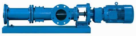
3 Section: MOYNO 2000 PUMPS Page: 1 Date: July 2005 SERVICE MANUAL MOYNO 2000 CC PUMPS 1-1. INTRODUCTION 1-2. GENERAL The Moyno 2000 pump is a progressing cavity pump. A single helical rotor rolling eccentrically in the double-threaded helix of the stator creates the pumping action. In its revolution, the rotor forms, in conjunction with the stator, a series of sealed cavities 180 degrees apart. As the rotor turns, the cavities progress from the suction to the discharge. As one cavity diminishes, the opposing cavity increases at exactly the same rate. Thus, the sum of the two discharges is a constant volume. The result is a pulsationless, positive displacement flow SCOPE This service manual covers the installation and maintenance requirements for standard, close-coupled configuration of the Moyno 2000 pump line. Disassembly and assembly procedures are also covered in this manual NAMEPLATE DATA The pump nameplate, located on the drive adapter, contains important information relative to the operation and servicing of the pump. This information includes the direction of rotation arrow and the pump model and serial numbers. The model and serial numbers must be used when ordering spare parts Pump Rotation. A rotation arrow on the nameplate indicates the direction of rotation. Standard rotation of Moyno 2000 pumps is clockwise, when viewed from the driven end of the pump Model Number. The pump model number is a series of numbers and letters, which identifies the pump s basic design and materials of construction. A typical model number, for example, might be 1BB065CDQ3SA1AAAC, as shown on the nameplate in Figure 1-1. Figure 1-1. Typical nameplate showing rotation arrow, model, and manufacturing serial numbers. The first six numbers and letters identify the pump s basic design characteristics. In the first space, a number identifies the number of stages in the pumping elements. This will generally be a 1 or 2. The second position, the letter B, designates the pump type as being close-coupled. In the third position, a letter designates the pump s drive train (con rod/gear joint/drive shaft): A One size smaller than element (175/220 only) B Same size as element C Same size as element, but larger gearbox drive flange and drive shaft size (175/220/345 only) The next three positions, always numbers, identify the pumping element in terms of theoretical gallons per 100 revolutions. The next 3 positions, always letters, describe the pump s materials of construction in component groups of parts. The first letter in this group identifies the material of the suction housing casting. The second letter indicates the material used in the rotating parts, i.e., the drive shaft, con rod, rotor, and other metallic parts in contact with the material being pumped. The third letter indicates the material of the stator. It identifies only the stator material and not that of the tube in which the stator is placed. The tube, a non-wetted part, is always alloy steel. The standard designation such as the CDQ used in our example would result in the following: C = Cast iron suction chamber D = Hardened alloy steel internals including drive shaft, con rod, gear joint, and rotor Q = Nitrile (NBR) stator (70 durometer hardness) The next position is a number identifying the current pump revision. This manual corresponds to Revision 3. The next three letters indicate the sealing system of the pump. The first letter identifies whether packing, a single seal, or a double seal is being used. The second and third positions indicate specific seal or packing model and type used. A typical trim code is SA1, designating the following: S = Single mechanical seal A1 = John Crane type 2100 SiC/SiC/Viton/316 The next letter indicates rotor variations. The most common designation is an A for standard size, chrome plated. Other options are available including special coatings, undersizes, and oversizes.
4 Page 2 The next letter indicates whether there are any special options being used in the pump, typically this is an A for no special options. The next letter indicates the suction configuration. For this pump an A is used designating a standard flanged pump. The last letter indicates the drive configuration and flange/shaft/seal size. In our close coupled pump nameplate the C designates a 250mm flange and 45mm shaft INSTALLATION 2-2. GENERAL Accessibility to the pump and adequate clearance should be prime considerations in any installation. Enough space should surround the unit so that maintenance can be performed with ease PIPING 1. Suction piping should be as short as possible. Normally, the suction line should be the same diameter as the pump suction; however, conditions such as high viscosity or required minimum flow velocities may dictate otherwise. Long-sweep 90-degree elbows or 45-degree elbows should be used instead of the standard elbow. Avoid using suction piping loops, which trap air. 2. Discharge piping diameter should generally be as large as the discharge port unless fluid conditions indicate otherwise. 3. An easily removable section of piping, at least twice as long as the stator, should be mated to the discharge port. This will allow the rotor and stator to be removed without having to remove the complete pump from the base Foundation. For maximum pump-driver unit life, each unit should be mounted on a strong steel baseplate. The baseplate should be mounted on a firm foundation. The motors should be supported on close-coupled configurations above 30 HP OPERATION 3-2. INITIAL CHECK Before putting the pump into operation, the following items should be checked to ensure that each piece of equipment is installed correctly: 3-3. START-UP CAUTION: DRY OPERATION IS HARMFUL TO THE PUMP! Never allow the pump to operate without liquid, as dry operation will cause premature wear of the stator and possible damage. The liquid being pumped lubricates the stator. 1. Before operating the pump for the first time, fill it with liquid to lubricate the stator for the initial start-up. Note: If the pump is shut down temporarily, enough liquid will remain in the system to provide lubrication upon restarting. It is advisable to maintain the suction piping at a higher elevation than the centerline of the pump in order to contain some liquid in the pump at time of shutdown. 2. Once the pump has been filled with liquid, check for direction of pump rotation by momentarily starting and stopping the drive. See pump nameplate for correct rotation. 3. Start seal flush water if so equipped. 4. Start pump Packing Leakage. The packed stuffing box is designed to control leakage, not stop it completely. Leakage is necessary to reduce friction and dissipate heat. In a new pump, before the packing has had a chance to seat properly, excessive leakage through the stuffing box is common. Frequent adjustments of the packing gland may be necessary during the first few hours of operation in order to compress and seat the packing. See Section MAINTENANCE 4-2. GENERAL The Moyno 2000 CC pump has been designed for a minimum of maintenance, the extent of which is routine adjustment of the packing. The pump is one of the easiest to maintain because the main elements are very accessible and require few tools to disassemble Packing Adjustment. Packing gland nuts (see Figure 4-1) should be evenly adjusted. Overtightening the packing gland may result in premature packing failure and possible damage to the shaft and gland. Electrical connections. Gauges and other instruments. Pump rotation. Rotation is indicated on the pump nameplate. All valves should be open on both suction and discharge sides of pump. Seal flush systems if required should be operational. Double seals require flushing between faces. CAUTION: This is a positive displacement pump. Do not operate it against a closed valve. Figure 4-1. Cross Section of Packing Housing

5 When packing is new, frequent minor adjustments during the first few hours of operation are recommended in order to compress and seat the packing. 1. Upon initial start-up of the pump, adjust the gland nuts for a leakage rate of drops per minute until the packing has seated and adjusted to the operating temperature (approximately minutes). 2. If leakage is excessive after 15 minutes of operation, tighten the gland nuts ¼ of a turn. 3. Tighten the gland nuts ¼ of a turn after an additional 15 minutes if necessary and repeat this procedure until a desired leakage of 1-2 drops per minute is obtained. Adding grease may also reduce leakage by providing a barrier at the lantern ring. CAUTION: Do not tighten until zero leakage is obtained. Overtightening the packing gland may result in accelerated wear on the packing and damage to the shaft. In those situations where no packing leakage can be tolerated, consult your Moyno Authorized Representative. Area To Lubricate Packing 4-4. PACKING REPLACEMENT Approved Lubricant or Equivalent ACG-2 (Dubois Chemical, Inc.) Note: In this section, the first reference to each pump part will be followed by a number or a letter in parentheses ( ). These numbers and letters are used to identify the pump parts and hardware items in the Exploded Views in Section When tightening the gland nuts can no longer regulate leakage, remove and replace the packing. The entire pump does not need to be disassembled to replace the packing. Briefly, replace as follows: 1. Remove packing gland nuts and slide gland halves (152) back along drive shaft (400). 2. Use a packing puller tool (see Figure 4-2) to remove the packing (150). 6. Adjust packing per Section DISASSEMBLY Page 3 Note: In this section and in following sections on CLEANING, INSPECTION, and ASSEMBLY, the first reference to each pump part will be followed by a number or letter in parentheses ( ). These numbers and letters are those used to identify the pump parts and hardware items in the Exploded Views in Section DISCONNECT PUMP 1. Disconnect the power source. 2. Close suction and discharge valves to isolate the pump from the line STATOR REMOVAL 1. Remove section of discharge pipe attached to discharge flange (200). 2. Remove discharge flange by unbolting from stator clamp ring (210) and remove stator gasket (510). Use a screwdriver tip to remove stator retaining ring (480), stator clamp ring (210), and pump support (220) from stator (500). 3. Unbolt stator clamp ring (210) from suction housing and remove stator from rotor (turning stator clockwise while removing will ease disassembly). Remove the stator retaining ring. Remove stator clamp ring from stator. See Figure 5-1. for the typical retaining ring removal procedure. Figure 5-1. Typical Retaining Ring Removal Figure 4-2. Packing Removal Tool 3. Inspect surface of drive shaft for excessive wear or grooves due to packing rub. If shaft is worn, or is badly scored or grooved, it should be replaced. 4. If drive shaft is not worn, install a lantern ring and four packing rings, lubricating them before installation with a good grade of packing grease. Be sure to stagger the packing ring joints at 90-degree increments. Note: The stuffing box is supplied with four rings installed, a fifth ring may be added after initial compression. CAUTION: ALWAYS USE A PROPER PACKING TAMPER TOOL TO INSTALL PACKING. Do not use a pointed or sharp tool, as damage to the packing material or drive shaft could result. To assure proper shaft lubrication, never use a one-piece spiral wrap packing. 5. Replace packing gland halves and secure with packing gland and nuts (156) SUCTION HOUSING REMOVAL 1. Remove four bolts and lock washers (230) holding the suction housing (100) to the drive adapter (10). 2. Pull the suction housing toward the rotor and away from the adapter housing. Place a block of wood under the suction housing to prevent it from dropping as you pull it away from the adapter housing ROTOR/CON ROD/DRIVE SHAFT ASSEMBLY REMOVAL 1. Slide the slinger ring (60) along the drive shaft (400), towards the gear reducer, exposing the drive pin (70). 2. With a punch and hammer, tap the drive pin from the drive shaft. 3. Carefully pull the rotor/con rod/drive shaft assembly from the gear reducer. Place the assembly aside for now. On larger sizes where it may be awkward to remove the whole rotating unit as one piece, the rotor can be remove first. Refer to section 5-8 for joint disassembly instructions.
6 Page PACKING HOUSING REMOVAL 1. Pull the packing housing (140) away from the drive adapter (10). Remove the O-ring (530). 2. Remove the gland nuts (156), studs (155), and packing gland halves (152). 3. Use a packing removal tool to remove two rings of packing (150), two lantern rings (151), and the last two rings of packing (150). OR 5-7. SEAL HOUSING REMOVAL 1. Pull the seal housing (140) from the drive adapter (10). Remove the O-ring (530). 2. Carefully push the stationary seal face from the adapter housing. 3. Carefully pull the rotating portion of the mechanical seal (150) from the drive shaft. The rubber bellows will adhere to the shaft after assembly and must be replaced if removed from the shaft. 4. It is sound practice to always replace packing (150) whenever the pump is disassembled ROTOR 1. To check for excessive rotor (470) wear, measure the rotor crest-to-crest diameter (see Figure 6-1.) and compare with the following chart: Rotor Size Standard Crest-to-Crest Diameter (Inches) The rotor size is designated by the fourth, fifth, and sixth numbers in the model number (i.e.,1bb065) ROTOR, DRIVESHAFT, AND CONNECTING ROD DISASSEMBLY 1. Remove the vent plug (440) and set screw (450) from the gear joint shell (410). 2. Remove six socket head screws (430) from head ring (420) and remove head ring and O-ring (540). Slide connecting rod/gear joint assembly off rotor head. Remove gear joint keys (360) and primary thrust plate (310) from rotor (470). 3. Slide gear joint shell (410) off gear ball/connecting rod assembly. Slide ring gear (350) off gear ball (300). 4. Clamp connecting rod (460) in vice and hold with pipe wrench and remove lock nut (330). Remove gear ball (300), secondary thrust plate (320), seal support (340), and gear joint seal (520) from connecting rod. 6. Repeat steps 2 through 5 for driveshaft joint disassembly. NOTE: It is recommended that each time the rotor and gear joint is disassembled, the rotor head O-ring (360) and gear joint seal (520) should be replaced Drive Adapter / Gearmotor Removal. Remove the four bolts and lock washers holding the drive adapter (10) to the gear reducer. Pull the drive adapter from the reducer Cleaning. Clean parts in a suitable cleaning solvent INSPECTION 6-2. DRIVESHAFT AND PACKING/SEALS 1. Inspect drive shaft (400) for scoring, burrs, cracks, etc. Replace as necessary. 2. It is sound practice to always replace O-rings and gear joint seals. 3. It is sound practice to replace mechanical seals when the pump is disassembled. Extreme care should be taken to protect the seal faces from damage. These are fragile; avoid touching the faces and keep them clean. Figure 6-1. Measuring Rotor Diameter 2. If the measured crest-to-crest diameter is within.010 in. of the standard value, the rotor is reusable provided that: a. The rotor surface is not cracked, pitted or deeply grooved (.030 in. or more). 3. Rotors with crest-to-crest diameters greater than.010 in. under the standard value should generally be replaced Stator. The best indication of stator wear (500) and the need for replacement is a drop in pump performance. Stators with interior surfaces that are pitted, grooved or gouged should also be replaced All Other Parts. Check for cracks, excessive wear, damage to threaded holes, burrs, etc. Replace as necessary. Replace O-rings (530) and both gaskets (510) at each disassembly and reassembly.

7 7-1. ASSEMBLY 7-2. LUBRICATION DURING ASSEMBLY 1. Gear Joints. Both gear joints should be packed with lubricant during assembly (Section 7-3). DO NOT use zerk fittings to lubricate gear joints after assembly. The pipe plugs (440) in the drive shaft head, drive shaft, and gear joint shell are vent plugs and MUST BE REMOVED during assembly of the gear joints to allow excess lubricant to vent from the gear joints. 2. Packing. Lubricate packing rings during assembly. Additional grease can be added after assembly through zerk fittings if installed in the side of the stuffing box. 3. Approved Lubricants: CAUTION: Do not mix different brands of lubricants for the same application. Area to Lubricate Gear Joints & Packing Approved Lubricant or Equivalent ACG-2 (Dubois Chemical, Inc.) 7-3. DRIVESHAFT AND ROTOR GEAR JOINT ASSEMBLY 1. Insert the primary thrust plate (310) into driveshaft/rotor head, flat side first. Thrust plate and driveshaft/rotor head surfaces must be flush to assure proper assembly and operation of the pump (see Figure 7-1.). Figure 7-1. Rotor Thrust Plate Seating Detail 2. Assemble the gear joint by first fitting a gear joint seal (520) onto the connecting rod assembly (460). The seal must be positioned so that the flat face of the seal neck fits into the seal retainer component of the connecting rod assembly. Apply a small coating of approved gear joint lubricant to the inside surfaces of the seal. 3. Apply a small amount of lubricant to the flat face of the seal support (340) and slide it onto the connecting rod so that the flat face and radius of the support is against the seal (520). 4. Grease the concave spherical surface of the rear thrust plate (320) and position thrust plate against the seal (520) with the lip on the outside diameter of the seal fitting the step on the back side of the thrust plate. 5. Apply a film of grease to the splines on the inside of the gear ball (300). Install gear ball on connecting rod (460), with counter-bored end (end without splines) first on connecting rod. Gear ball should slide freely against shoulder on connecting rod. Place lock nut (330) on connecting rod and tighten against gear ball. Apply grease to spherical surfaces and teeth of gear ball. Page 5 6. Apply grease to the teeth of the ring gear (350), and slide ring gear into the gear ball. When ring gear is in place, keyways should be facing the lock nut end of connecting rod. 7. Apply a thin coating of grease to the spherical surface of the thrust plate (310) already installed in the driveshaft/ rotor head. Fill the recessed area in the driveshaft/rotor head with grease. Place keys (360) in the keyways in the ring gear. 8. Align the keys in the ring gear with the keyways in the driveshaft/rotor head and slide assembled gear joint components into the gear joint shell (410). Check to be sure the keys are properly engaged in the driveshaft/rotor head and ring gear. 9. Lightly lubricate the O-ring (540) and then position the O- ring in outside diameter O-ring groove slot of the gear joint head ring (420). 10. Slide the head ring (420) over the connecting rod (460), O- ring side first, towards the assembled gear joint components and driveshaft/rotor gear joint shell (410). Align holes in head ring (420) with six threaded holes in end of gear joint shell and install six stainless socket head screws (430). Tighten the six socket head screws evenly, checking to ensure O-ring (540) remains in place. When tightened properly, a small gap of a few thousandths of an inch may exist between the shell (410) and gear joint head ring (420). Note: After assembling the first joint the gear joint shell (410) for the second joint must be placed on the con rod before assembly on the second joint begins. 11. Excess grease in the assembly will be purged from the vent hole in the gear joint retainer (420) while the socket head screws are tightened. Rotate the free end of the connecting rod in a circular motion to assure that the joint is free and assembled properly. This will also help to purge excess grease from the assembly. 12. Install the stainless steel pipe plug (440) in the vent hole in the shell and tighten. 13. Coat the rotor (470) contour with waterless hand cleaner, glycol, or other lubricant compatible with the stator elastomer. Insert rotor into stator. NOTE: To ease assembly, turn the stator counter-clockwise while assembling onto the rotor. 15. For Pump Models 065 / 090 / 115 / 175 / 220 / 345 a. Secure the pump support (220) to the suction housing (100) with two hex head screws, lock washers, and nuts (230/260). 16. Slide stator clamp rings (210) on both ends of the stator (500) and secure in position with retaining rings (480) Drive Adapter Assembly. Place the drive adapter (10) against the flange of the gear reducer and secure with four hex head screws and washers. Tighten evenly. Apply a liberal amount of anti-seize lubricant to the entire surface of the reducer shaft. Note: The drive adapter (10) must be mounted to the baseplate before the gearbox can be mounted. For units with a double or cartridge seal please refer to section 7-7 before mounting the gearbox to the drive adapter PUMPS WITH SINGLE MECHANICAL SEAL 1. Carefully slide the rotating portion of the mechanical seal (150) onto the drive shaft up against the set collar (160). The seal face should be facing out, away from the connecting rod (460). Apply a small amount of grease to the ID of the rubber bellows making it easier to slide onto the shaft.
8 Page 6 2. Gently push the stationary portion of the mechanical seal into the recess in the seal housing (140). Place the O-ring (530) on the shoulder of the seal housing. 3. Slide the seal housing into the drive adaptor (10). Secure the suction housing (100) to the drive adapter (10) with four hex head screws and lock washers (20/30). Take care to be sure the o-ring (530) is placed on the seal housing (140) before assembling. 4. Next, carefully slide the rotating/stator assembly first through the suction housing (100) and then through the seal stationary face in the seal housing and over the gear reducer shaft. Align the holes by rotating the motor fan. Use a punch to align the holes axially being careful not to damage the mechanical seal. 5. Replace the drive pin (70) and slide the slinger ring (60) onto the shaft over the drive pin (70) OR 7-6. PUMPS WITH COMPRESSION PACKING 1. The standard packing set (150) consists of four braided packing rings. The lantern ring (151) must be ordered separately. 2. Wipe a film of lubricant on each packing ring and install two rings in the packing housing (140). Push each ring firmly in place, staggering the splits in each ring 90 degrees. 3. Install the lantern ring and the last two rings of packing, staggering the splits as before. 4. Install packing gland studs (155), packing gland halves (152), and gland nuts (156). Tighten nuts finger tight at this point. Place the O-ring (530) on the shoulder of the packing housing. 5. Slide the packing housing into the drive adaptor (10). Secure the suction housing (100) to the drive adapter (10) with four hex head screws and lock washers (20/30). Take care to be sure the o-ring (530) is placed on the seal housing (140) before assembling. 6. Next, carefully slide the rotating/stator assembly first through the suction housing (100) and then through the seal stationary face in the seal housing and over the gear reducer shaft. Align the holes by rotating the motor fan. Use a punch to align the holes axially. 7. Replace the drive pin (70) and slide the slinger ring (60) onto the shaft over the drive pin (70). OR 7.7. PUMPS WITH DOUBLE OR CARTRIDGE MECHANICAL SEALS 1. Apply a small amount of grease to the ID of the rubber bellows or o-rings making it easier to slide onto the shaft. 2. Gently push the stationary portion of the mechanical seal into the recess in the seal housing and housing plate (140) (Cartridge seals are self contained.) Insert rotating seal assemblies in to the seal housing and bolt cover plate to the housing with four cap head screws. Place the O-ring (530) on the shoulder of the seal housing. 3. Hold the seal housing (150) in the drive adaptor (10). Secure the gearmotor to the drive adapter with four bolts. Gently rest the seal on the gearbox shaft. Secure the suction housing (100) to the drive adapter (10) with four hex head screws and lock washers (20/30). Take care to be sure the o-ring (530) is placed on the seal housing (140) before assembling. 4. Next, carefully slide the rotating/stator assembly first through the suction housing (100) and then through the seal stationary face in the seal housing and over the gear reducer shaft. Align the holes by rotating the motor fan. Use a punch to align the holes axially being careful not to damage the mechanical seal. 5. Replace the drive pin (70) and slide the slinger ring (60) onto the shaft over the drive pin (70) 7-8. SUCTION HOUSING/STATOR ASSEMBLY 1. Bolt stator clamp ring (210) to the suction housing (100) with six hex head screws and lock washers (230/260). 2. Bolt stator clamp ring (210) to the discharge flange (200) with six hex head screws and lock washers (230/260) PUMP CONNECTIONS 1. Connect suction and discharge piping to the pump. Check INSTALLATION instructions in Sections 2-1. through Review OPERATION instructions in Sections 3-1. through 3-4. before starting the pump STORAGE Short-Term Storage. Storage of six months or less will not damage the pump. However, to ensure the best possible protection, the following is advised: 1. Store pump inside whenever possible or cover with some type of protective covering. Do not allow moisture to collect around pump. 2. Remove drain plug to allow the pump body to drain and dry completely. 3. See drive manufacturer s instructions for motor and/or drive storage. 4. See OPERATION, Sections 3-1. through 3-4., before startup. Be sure all lubricants are in good condition. Long-Term Storage. If pump is to be in storage for more than six months, perform the above short-term storage procedures with the exception of Step 4. In its place it is suggested that the stator be removed to avoid developing a set condition. In addition: Apply rust inhibitor to all unpainted cast iron and machined carbon steel surfaces RECOMMENDED SPARE PARTS Your Moyno 2000 pump has been designed and built to minimize overall operating cost. All wearable parts are replaceable. A recommended inventory of spare parts is dependent upon the application and the importance of continued operation. To minimize downtime, we recommend the following spare parts be in your inventory: This is a suggested list. For further assistance, contact your Moyno representative. (1) Rotor (1) Stator (2) Stator Gaskets (1) Con Rod (1) Mechanical Seal / Packing (2) Gear Joint Kits
9 Page HARDWARE LIST BB022 THRU BA175 Ref No. 20 Hex Screw-200mm M10 X Lock Washer M10 40 Hex Nut M10 X Hex Screw-250mm 30 Lock Washer 40 Hex Nut 20 Hex Screw-300mm 30 Lock Washer 40 Hex Nut 20 Hex Screw-350mm 30 Lock Washer 40 Hex Nut 20 Hex Screw-450mm 30 Lock Washer 40 Hex Nut 50 Pipe Plug 110 Hex Screw 120 Lock Washer 130 Pipe Plug 153 Socket Pipe Plug 154 Grease Fitting 155 Gland Stud-Small Shaft 155 Gland Stud-Large Shaft 156 Hex Nut-Small Shaft 156 Hex Nut-Large Shaft 170 Socket Pipe Plug 235 Hex Screw 236 Lock Washer 237 Hex Nut Description BB022 BB036 BB050 BB065 BB090 BB115 BA175 M20 x 55 M12 x 50 M12 M12 x Hex Screw M20 x 50 M20 x 45 M20 x 55 M20 x Lock Washer M20 x 50 M Hex Screw M16 x 40 3/4-10 x 1.75" 255 Hex Screw 3/4-10 x 2.25" 260 Lock Washer 430 Socket Screw 440 Socket Pipe Plug 450 Set Screw 3/4" NPT M16 x 50 M20 x 55 M16 M20 1" NPT 1/4-27 NPT 1/4-27 NPT M8 x 1.25 x 50 M10 x 1.5 x 60 M10 x 1.5 x 60 M8 x 1.25 M12 x 60 M12 M12 x 1.75 M10 x 1.5 1/4-18 NPT M12 x 65 M12 M12 x 1.75 M16 x 70 M16 M16 x 2.0 M10 x 1.5 M20 x 50 M16 x 45 M16 3/4" #10-24 x.50" 1/4-20 x.625" 1/4-17 NPT 5/16-18 x.625"
10 Page HARDWARE LIST BA220 THRU BC345 Ref No. Description BA220 BB175 BB220 BB345 BC175 BC220 BC Hex Screw-200mm 30 Lock Washer 40 Hex Nut 20 Hex Screw-250mm M12 x Lock Washer M12 40 Hex Nut M12 x Hex Screw-300mm 30 Lock Washer 40 Hex Nut 20 Hex Screw-350mm 30 Lock Washer 40 Hex Nut 20 Hex Screw-450mm 30 Lock Washer 40 Hex Nut 50 Pipe Plug 110 Hex Screw M20 x Lock Washer 130 Pipe Plug 153 Socket Pipe Plug 154 Grease Fitting 155 Gland Stud-Small Shaft M10 x 1.5 x Gland Stud-Large Shaft M10 x 1.5 x Hex Nut-Small Shaft M10 x Hex Nut-Large Shaft M10 x Socket Pipe Plug 235 Hex Screw 236 Lock Washer 237 Hex Nut 240 Hex Screw 245 Lock Washer 250 Hex Screw 255 Hex Screw 260 Lock Washer 430 Socket Screw 440 Socket Pipe Plug 450 Set Screw M12 x 65 M12 M12 x 1.75 M16 x 70 M16 M16 x 2.0 M12 x 1.75 x 70 M12 x /4-18 NPT 3/4" NPT M20 x 60 M20 1" NPT 1/4-27 NPT 1/4-27 NPT M12 x 1.75 x 70 M12 x 1.75 M12 x 50 M12 M12 x 1.75 M20 x 60 M20 3/4-10 x 1.75" 3/4-10 x 2.25" 3/4" 1/4-20 x.625" 1/4-17 NPT 5/16-18 x.625" M16 x 55 M16 M16 x 2.0
11 11-1. PARTS LIST BB022 THRU BA175 Ref No. 10 Drive Adapter -200mm 10 Drive Adapter-250mm 10 Drive Adapter-300mm 10 Drive Adapter-350mm 10 Drive Adapter-450mm 60 Slinger Ring-Small Shaft 60 Slinger Ring-Large Shaft 70 Drive Pin Description BB022 BB036 BB050 BB065 BB090 BB115 BA Suction Housing-ANSI Suction Housing-Metric Packing Housing-Small Shaft Packing Housing-Large Shaft Packing Set-Small Shaft Packing Set-Large Shaft Lantern Ring-Small Shaft Lantern Ring-Large Shaft Packing Gland Half-Small Shaft Packing Gland Half-Large Shaft Seal Housing Seal Housing Mechanical Seal Small Shaft Mechanical Seal Large Shaft Mechanical Seal-MG12-Small Shaft Mechanical Seal-MG12-Large Shaft Shaft Collar-Small Shaft Shaft Collar-Large Shaft Discharge Flange-ANSI Discharge Flange-Metric Clamp Ring AG0933 AG Pump Support Pump Support-2 stage Pump Support 230 Pump Support-2 stage 300 Gear Ball 310 Thrust Plate 320 Thrust Plate 330 Lock Nut 340 Seal Support 350 Ring Gear 360 Key 400 Dive Shaft-Plate-Small Shaft 400 Drive Shaft-Non Plate-Small Shaft 400 Dive Shaft-Plate-Large Shaft 400 Drive Shaft-Non Plate-Large Shaft 410 Gear Joint Shell 420 Head Ring 460 Connecting Rod Rotor - TS - 1 stage C71EF1 C71EG1 C71E51 C71FH1 C71F91 C71GJ Rotor - 316ss - 1 stage C81EF1 C81EG1 C81E51 C81FH1 C81F91 C81GJ1 470 Rotor - TS - 2 stage C72EF1 C72EG1 C72E51 C72FH1 C72F91 C72GJ1 470 Rotor - 316ss - 2 stage C82EF1 C82EG1 C82E51 C82FH1 C82F91 C82GJ1 480 Retaining Ring AF0085 AG0085 AH0085 AK Stator - 1 Stage C310FQ C310GQ C3150Q C310HQ C3190Q C310JQ C310KQ 500 Stator - 2 stage C320FQ C320GQ C3250Q C320HQ C3290Q C320JQ 510 Stator Gasket BF085Q BG085Q BH085Q BK085Q 520 Gear Joint Seal 530 O-ring 540 O-ring AE0951 PE0981 PE0982 RE0581 PE0891 AE0952 RE PE0911 PE034D PE087Q TH211Q PE113Q AF0951 PF0981 PF0982 RF0581 PF0891 AF0952 RF PF0911 PF034D PF087Q J10111 PF113Q AG0951 PG0981 PG0982 RG0581 PG0891 AG0952 RG PG0911 PG034D PG087Q Note: For Ref Nos the Q in the designation represents Nitrile (Buna N), The Q in part number is substituted with an B for EPDM or F for Flouroelastomer(Viton) Page
12 Page PARTS LIST BA220 THRU BC345 Ref No. Description BA220 BB175 BB220 BB345 BC175 BC220 BC Drive Adapter -200mm 10 Drive Adapter-250mm Drive Adapter-300mm Drive Adapter-350mm Drive Adapter-450mm Slinger Ring-Small Shaft Slinger Ring-Large Shaft Drive Pin Suction Housing-ANSI Suction Housing-Metric Packing Housing-Small Shaft Packing Housing-Large Shaft Packing Set-Small Shaft Packing Set-Large Shaft Lantern Ring-Small Shaft Lantern Ring-Large Shaft Packing Gland Half-Small Shaft Packing Gland Half-Large Shaft Seal Housing Seal Housing Mechanical Seal Small Shaft Mechanical Seal Large Shaft Mechanical Seal-MG12-Small Shaft Mechanical Seal-MG12-Large Shaft Shaft Collar-Small Shaft Shaft Collar-Large Shaft Discharge Flange-ANSI Discharge Flange-Metric Clamp Ring Pump Support Pump Support-2 stage 230 Pump Support Pump Support-2 stage 300 Gear Ball AG Thrust Plate PG Thrust Plate PG Lock Nut RG Seal Support PG Ring Gear AG Key RG Dive Shaft-Plate-Small Shaft Drive Shaft-Non Plate-Small Shaft Dive Shaft-Plate-Large Shaft Drive Shaft-Non Plate-Large Shaft Gear Joint Shell PG0911 PH Head Ring PG034D PH034D 460 Connecting Rod Rotor - TS - 1 stage C71HK C71HK Rotor - 316ss - 1 stage C81HK1 C81HK1 470 Rotor - TS - 2 stage C72HK C72HK Rotor - 316ss - 2 stage C82HK1 C82HK1 480 Retaining Ring AK Stator - 1 Stage C310KQ C3145Q C310KQ C3145Q 500 Stator - 2 stage C320KQ C320KQ Stator Gasket 520 Gear Joint Seal PG087Q 530 O-ring J O-ring PF113Q AH0951 PH0981 PH0982 RH0581 PH0891 AH0952 RH0761 BK085Q PH087Q Note: For Ref Nos the Q in the designation represents Nitrile (Buna N), The Q in part number is substituted with an B for EPDM or F for Flouroelastomer(Viton)
13 Page 11
14 Page SEAL SET DIMENSIONS

15 14-1. TROUBLESHOOTING CHART Page 13
16 Your Authorized Service Distributor is: 2005 by Moyno, Inc. Printed in U.S.A. Moyno is a registered trademark of Moyno, Inc.
SERVICE MANUAL. MOYNO 2000 Pumps G2/G3 Enhanced Feed Models Version 5 Models
 SERVICE MANUAL MOYNO 2000 Pumps G2/G3 Enhanced Feed Models Version 5 Models TABLE OF CONTENTS Page 1-1. INTRODUCTION... 1 1-2. GENERAL 1 1-3. NAMEPLATE DATA... 1 1-4. Pump Rotation 1 1-5. Model Number
TABLE OF CONTENTS 1-1. INTRODUCTION
 SERVICE MANUAL TABLE OF CONTENTS Page 1-1. INTRODUCTION...1 1-2. GENERAL...1 1-3. NAMEPLATE DATA...1 1-4. Pump Rotation...1 2-1. INSTALLATION...1 2-2. GENERAL...1 2-3. PIPING...1 2-4. Suction Piping...1
SERVICE MANUAL 200 SERIES MOTORIZED 20352, 20452, 20551, 20552, AND MODELS
 Section: MOYNO 500 PUMPS Page:1 of 4 Date: March 1, 1998 SERVICE MANUAL MOYNO 500 PUMPS 200 SERIES MOTORIZED 20352, 20452, 20551, 20552, 22051 AND 22052 MODELS DESIGN FEATURES Housing: AISI 316 stainless
OPERATION ASSEMBLY INSTRUCTIONS AND PARTS LIST FOR L10 DRIVE END (FRAME SIZES 1L10, 2L10, 3L10, 1L10H, 2L10H, 3M8, 3P6, 6P6, 9P6)
") Section: L and J FRAME PUMPS Page: 1 Date: (Revision 5/88) OPERATION ASSEMBLY INSTRUCTIONS AND PARTS LIST FOR L10 DRIVE END (FRAME SIZES 1L10, 2L10, 3L10, 1L10H, 2L10H, 3M8, 3P6, 6P6, 9P6) GENERAL The
Section: L and J FRAME PUMPS Page: 1 Date: (Revision 5/88) OPERATION ASSEMBLY INSTRUCTIONS AND PARTS LIST FOR L10 DRIVE END (FRAME SIZES 1L10, 2L10, 3L10, 1L10H, 2L10H, 3M8, 3P6, 6P6, 9P6) GENERAL The
300 SERIES 331, 332, 333, 344, 356 AND 367 MODELS
 Section: MOYNO 500 PUMPS Page: 1 of 8 Date: March 1, 1998 SERVICE MANUAL MOYNO 500 PUMPS 300 SERIES 331, 332, 333, 344, 356 AND 367 MODELS Mechanical Seal Models Packing Gland Models MODELS DESIGN FEATURES
METERING/DOSING PUMP CLOSE-COUPLED B4015D, B4050D, B4100D, B4190D, B2400D, AND B4400D MODELS
 Section: METERING/DOSING PUMPS Page: 1 of 5 Date: July 2009 SERVICE MANUAL METERING/DOSING PUMP CLOSE-COUPLED B4015D, B4050D, B4100D, B4190D, B2400D, AND B4400D MODELS DESIGN FEATURES Suction Housing:
TABLE OF CONTENTS. Page
 TABLE OF CONTENTS Page 1-1. INTRODUCTION...1 1-2. GENERAL...1 1-3. NAMEPLATE DATA...1 1-4. Pump Rotation...1 1-5. Model Number...1 1-6. Frame Designation...1 1-7. Type Designation...2 1-8. Trim Code...2
DELTA O-RING CARTRIDGE SEAL ASSEMBLY AND INSTALLATION INSTRUCTIONS INTRODUCTION:
 DELTA O-RING CARTRIDGE SEAL ASSEMBLY AND INSTALLATION INSTRUCTIONS INTRODUCTION: These instructions are provided to familiarize the user with the seal and its use. The instructions must be read carefully
DELTA O-RING CARTRIDGE SEAL ASSEMBLY AND INSTALLATION INSTRUCTIONS INTRODUCTION:
 DELTA O-RING CARTRIDGE SEAL ASSEMBLY AND INSTALLATION INSTRUCTIONS INTRODUCTION: These instructions are provided to familiarize the user with the seal and its use. The instructions must be read carefully
Specifications Information and Repair Parts Manual , , , &
 Please read and save this Repair Parts Manual. Read this manual and the General Operating Instructions carefully before attempting to assemble, install, operate or maintain the product described. Protect
INSTRUCTION AND REPAIR MANUAL MODELS 341A, 342A AND 344A 6
 SECTION 6 ITEM 0 DATED JUNE 1998 SUPERSEDES ITEMS 1, 2, DATED MARCH 1992 INSTRUCTION AND REPAIR MANUAL MODELS 1A, 2A AND A 6 NOTE This repair manual is applicable to pump Models 1A, 2A and A. All photos
Scope. Applicability. Caution. I & M CV3000 Series. Storage. Installation & Maintenance Instructions for Marwin CV3000 Series Three Piece Ball Valves
 I & M CV3000 Series 3170 Wasson Road Cincinnati, OH 45209 USA Phone 513-533-5600 Fax 513-871-0105 marwin@richardsind.com www.marwinvalve.com Installation & Maintenance Instructions for Marwin CV3000 Series
BEARING FITS INCHES (MM)
") CASING- Visually inspect for signs of wear, corrosion, or pitting. The casing should be replaced if wear exceeds Ys" deep. Check gasket surface for signs of corrosion or irregularities. IMPELLER- Visually
CASING- Visually inspect for signs of wear, corrosion, or pitting. The casing should be replaced if wear exceeds Ys" deep. Check gasket surface for signs of corrosion or irregularities. IMPELLER- Visually
KP-C Series. Close Coupled End Suction Centrifugal Pumps. Installation, Operation and Maintenance
 KP-C Series Close Coupled End Suction Centrifugal Pumps Installation, Operation and Maintenance PUMP MODEL NOMENCLATURE KP - 8 x 6 x 16 - E C - AI - BCM Pump Series Suction Pipe Size (in) Discharge Pipe
255 Cartridge Dual Seal
 MECHANICAL SEAL INSTALLATION INSTRUCTIONS 255 Cartridge Dual Seal Installation Instructions SEAL INSTALLATION Preparation Determine if the pump is in good condition. A. Check the shaft or sleeve. 1. Remove
Operation & Maintenance Manual 4900 Series Pipeline Injection Pumps Bulletin 150
 340 West Benson Avenue Grantsburg, WI 54840 1-800-366-1410 715-463-5177 www.northern-pump.com Table of Contents Introduction... 3 Rotation... 4 Hydraulic Balance... 5 Cautionary Statements... 6 Pump Installation...
Impeller Replacement
 Impeller Replacement Threaded Shaft Frame Mount H 806 Clockwise Rotation Volute shown. 1149 0794 1 Unfasten hardware holding volute to bracket. Remove volute to expose impeller. Peel off old volute gasket
GT-200 GATE VALVES PN16, Screwed end
 Document No. : MD-QO-04-281 Date : 2009/07 /17 Version : 1.0 GT-200 GATE VALVES PN16, Screwed end USER MANUAL Modentic Industrial Corporation 14F-1,No.57Taya Rd.,Taichung,Taiwan,R.O.C. Email:modentic@ms9.hinet.net
SANITARY/HYGIENIC NON-MOTORIZED
 Section: MOYNO 500 PUMPS Page: 1 of 4 Date: March 2002 SERVICE MANUAL MOYNO 500 PUMPS SANITARY/HYGIENIC NON-MOTORIZED 331, 332, 333 AND 344 MODELS SANITARY MODELS These pumps include housings polished
SERVICE MANUAL Moyno Mag Drive Series Motorized Pumps with Magnetic Drives 331, 332, 333, 344 MODELS
 SERVICE MANUAL Moyno Mag Drive 500 300 Series Motorized Pumps with Magnetic Drives 331, 332, 333, 344 MODELS Section: Mag Drive 500 Pumps Page: 1 of 4 Date: January 2010 DESIGN FEATURES Housing: PVC or
McCannalok HIGH PERFORMANCE BUTTERFLY VALVE OPERATION AND MAINTENANCE MANUAL. The High Performance Company
 McCannalok HIGH PERFORMANCE BUTTERFLY VALVE OPERATION AND MAINTENANCE MANUAL The High Performance Company Table of Contents Safety Information - Definition of Terms... 1 Introduction... 1 Installation...
SERIES PC INSTRUCTION AND OPERATION MANUAL
 MEGGA SERIES PC INSTRUCTION AND OPERATION MANUAL Models PCT and PCF Close-coupled and frame-mounted single-stage horizontal end-suction pumps. WARNING: Read this manual before installing or operating this
TECHNICAL SERVICE MANUAL
 Electronic copies of the most current TSM issue can be found on the Viking Pump website at www.vikingpump.com TECHNICAL SERVICE MANUAL HEAVY-DUTY Stainless steel BRACKET MOUNTED PUMPS SERIES 127 AND 4127
INSTRUCTION AND REPAIR MANUAL
 SECTION ITEM 0A DATED JANUARY 999 SUPERSEDES SECTION ITEM 0A DATED JULY 99 INSTRUCTION AND REPAIR MANUAL MODEL 4A-5A-A and 0B SINGLE STAGE and TWO STAGE This repair manual is applicable to pump models
Maintenance Information
 45528270 Edition 1 June 2007 Barring Motor T480 Series Maintenance Information Save These Instructions WARNING Always wear eye protection when operating or performing maintenance on this Barring Motor.
250L Cartridge Dual Seal
 INSTALLATION, OPERATION AND MAINTENANCE INSTRUCTIONS 250L Cartridge Dual Seal Installation, Operation and Maintenance Instructions TABLE OF CONTENTS 1.0 Cautions...2 2.0 Transport and Storage...2 3.0 Description...2
Northern Pump A Division of McNally Industries, LLC
 Operation & Maintenance Manual for Northern 4900 Injection Operation & Maintenance Manual For Northern 4900 Injection Northern Pump A Division of McNally Industries, LLC 340 West Benson Avenue Grantsburg,
Bray/Mckannalok Butterfly Valve Series 40/41/42/43/44/45 Installation Manual Technical Bulletin No Date: May 2004/Page 1 of 6
 Date: May 2004/Page 1 of 6 Bray/McCannalok Butterfly Valves Installation and Maintenance Instructions ANSI Classes 150 and 300 - Sizes 2-1/2 through 24 ANSI Classes 600 - Sizes 3 through 16 Bidirectional
316 Series Engine Driven DESCRIPTION MAINTENANCE SHIM ADJUSTMENT. Specifications Information and Repair Parts Manual
 Please read and save this Repair Parts Manual. Read this manual and the General Operating Instructions carefully before attempting to assemble, install, operate or maintain the product described. Protect
INSTRUCTION AND MAINTENANCE MANUAL: FL2/FL3 Series Pumps (Models: 15, 58, 75, 100 & 130)
") FL Series Pump INSTRUCTION AND MAINTENANCE MANUAL: FL/FL3 Series Pumps (Models: 5, 58, 75, 00 & 30) SANITARY POSITIVE DISPLACEMENT PUMPS Fristam Pumps Description This manual contains installation, operation,
FL Series Pump INSTRUCTION AND MAINTENANCE MANUAL: FL/FL3 Series Pumps (Models: 5, 58, 75, 00 & 30) SANITARY POSITIVE DISPLACEMENT PUMPS Fristam Pumps Description This manual contains installation, operation,
Operation & Maintenance Manual For 4900 Series Pumps Bulletin 134
 For 340 West Benson Avenue Grantsburg, WI 54840 1-800-366-1410 715-463-5177 www.northern-pump.com Table of Contents Introduction... 3 Cautionary Statements... 5 Pump Installation... 6 Removal from Installation...
John Crane Type 5620 and 5620PR Dual O-Ring Cartridge Seal Assembly and Installation Instructions
 I-5620/5620PR-A John Crane Type 5620 and 5620PR Dual O-Ring Cartridge Seal Assembly and Installation Instructions Foreword These instructions are provided to familiarize the user with the seal and its
155 CARTRIDGE SINGLE SEAL
 MECHANICAL SEAL INSTALLATION INSTRUCTIONS 155 CARTRIDGE SINGLE SEAL SEAL INSTALLATION Preparation Determine if the pump is in good condition. A. Check the shaft or sleeve. 1. Remove all burrs and sharp
CONTENTS. VIKING PUMP, INC. A Unit of IDEX Corporation Cedar Falls, IA USA SECTION TSM 710.1
 TECHNICAL SERVICE MANUAL industrial heavy duty motor speed pumps SERIES 4076 AND 4176 SIZES hle, ate and ale SECTION TSM 710.1 PAGE 1 of 8 ISSUE B CONTENTS Introduction....................... 1 Safety
Bray/McCannalok High Performance Butterfly Valve Operation and Maintenance Manual
 Bray/McCannalok High Performance Butterfly Valve Operation and Maintenance Manual Table of Contents Definition of Terms 1 Introduction 1 Installation 1 Maintenance 2 Stem Seal Replacement 4 Seat Replacement
INSTALLATION AND OPERATION
 WARNING: Because of the possible danger to persons(s) or property from accidents which may result from the improper use of products, it is important that correct procedures be followed. Products must be
DESCRIPTION MAINTENANCE
 Specifications Information and Repair Parts Manual 316F-95 and 316F-99 Please read and save this Repair Parts Manual. Read this manual and the General Operating Instructions carefully before attempting
 INSTRUCTIONS Your Ampco centrifugal pump is a rugged unit designed to provide years of low cost pumping service. There is a small amount of necessary care required to ensure you of this expected long service.
MAINTENANCE AND REPAIR INSTRUCTIONS
 MAINTENANCE AND REPAIR INSTRUCTIONS TYPE TH PUMPS Peerless Pump Company Indianapolis IN, 46207-7026 4849357 TABLE OF CONTENTS Maintenance Page 1 & 2 Disassembly Page 5 & 6 Impeller Clearance 3 Reassembly
INSTRUCTION MANUAL INTERNAL GEAR PUMP TITAN G-4124A SERIES=> FLANGED TITAN G-124A SERIES => FLANGED MODELS:
 INSTRUCTION MANUAL INTERNAL GEAR PUMP TITAN G-4124A SERIES=> FLANGED TITAN G-124A SERIES => FLANGED MODELS: G-H, G-HL, G-K, G-KK, G-L, G-LQ, G-LL, GLS, G-Q, G-QS 1 Contents Maintenance Thrust bearing adjustment
SERVICE MANUAL 200 SERIES MOTORIZED 20352, 20452, 20551, 20552, AND MODELS
 Section: MOYNO 500 PUMPS Page:1 of 4 Date: March 1, 1998 SERVICE MANUAL MOYNO 500 PUMPS 200 SERIES MOTORIZED 20352, 20452, 20551, 20552, 22051 AND 22052 MODELS DESIGN FEATURES Housing: AISI 316 stainless
225 CARTRIDGE DUAL SEAL
 225 CARTRIDGE DUAL SEAL MECHANICAL SEAL INSTALLATION INSTRUCTIONS PREPARATION 1 2 500.010" 0,25 mm 3 4.32 µ" 0,8 µm R a 1000 + ±.001".002" 0,025mm 0,050mm CAUTIONS These instructions are general in nature.
PROPELLER SHAFT & DIFFERENTIAL CARRIER SECTIONPD CONTENTS
 PROPELLER SHAFT & DIFFERENTIAL CARRIER SECTIONPD CONTENTS PREPARATION...2 PROPELLER SHAFT...5 On-Vehicle Service...6 Removal and Installation...7 Inspection...7 Disassembly...7 Assembly...8 ON-VEHICLE
OPERATION MANUAL INTERNAL GEAR PUMP. Models: NG-H, NG-HL, NG-K, NG-KK, NG-L, NG-LQ, NG-LL, NG-LS, NG-Q, NG-QS. Tel: Fax:
 OPERATION MANUAL INTERNAL GEAR PUMP Models: NG-H, NG-HL, NG-K, NG-KK, NG-L, NG-LQ, NG-LL, NG-LS, NG-Q, NG-QS. 1 Contents Pump Designation System Maintenance Thrust bearing adjustment Pressure Relief Valve
TECHNICAL SERVICE MANUAL
 Electronic copies of the most current TSM issue can be found on the Viking Pump website at www.vikingpump.com TECHNICAL SERVICE MANUAL industrial heavy duty motor speed pumps SERIES 4076 AND 4176 SIZES
Fisher 657 Diaphragm Actuator Sizes and 87
 Instruction Manual 657 Actuator (30-70 and 87) Fisher 657 Diaphragm Actuator Sizes 30 70 and 87 Contents Introduction... 1 Scope of Manual... 1 Description... 2 Specifications... 2 Installation... 3 Mounting
NEECO INDUSTRIES INC. INSTRUCTION MANUAL 7 1/16 10K SLAB GATE BODY
 INSTRUCTION MANUAL 7 1/16 10K SLAB GATE BODY INTRODUCTION The NF-700 type gate valves provided by Neeco Industries are full-bore through conduit non-rising stem manually (w/ball screw) operated valves.
Installation, Operation, and Maintenance Manual
 Installation, Operation, and Maintenance Manual SUMMIT PUMP MODEL SPPC SEALED GEAR JOINT PUMP i ii SUMMIT PUMP MODEL SPPC SEALED GEAR JOINT PUMP INSTALLATION, OPERATION AND MAINTENANCE MANUAL i. WARRANTY
Instruction and Maintenance Manual: FL II Series Pumps (Models: 15, 58, 75, 100 & 130)
") FLII Series Pu m p 1 Instruction and Maintenance Manual: FL II Series Pumps (Models: 15, 58, 75, 100 & 130) Sanitary Positive Displacement Pumps Fristam Pumps Description This manual contains installation,
FLII Series Pu m p 1 Instruction and Maintenance Manual: FL II Series Pumps (Models: 15, 58, 75, 100 & 130) Sanitary Positive Displacement Pumps Fristam Pumps Description This manual contains installation,
TC20 Chain Driven Power Take-Off Overhaul Instructions
 TC20 Chain Driven Power Take-Off Overhaul Instructions Table of Contents Section Page Introduction 4 Ordering Repair Parts 4 General Information 5 Special Tools 6 Disassembly See Page 2 Reassembly See
TYPE 5610V/5610VQ SINGLE O-RING CARTRIDGE SEAL
 1 Foreword These instructions are provided to familiarize the user with the seal and its designated use. The instructions must be read and applied whenever work is done on the seal, and must be kept available
NOTE: Visit our website at for video repair procedures, under the Tools section.
 Repair Instructions Hypro Repair Tools: Tool Box No. 3010-0168 1/4" Allen Wrench No. 3020-0008 Support Bars (2) No. 3010-0064 Port Brush No. 3010-0066 1/16" Allen Wrench No. 3020-0009 Brush Holder No.
Vickers. Overhaul Manual. Vane Pumps. Small and Large Series Combination Pumps VC(K)(S)-**-(*)*D*-6(1) VC(K)(S)-**-(*)-*-*D*-5(1)
(S)-**-(*)*D*-6(1) VC(K)(S)-**-(*)-*-*D*-5(1)") Overhaul Manual Vickers Vane Pumps Small and Large Series Combination Pumps VC(K)(S)-**-(*)*D*-6(1) VC(K)(S)-**-(*)-*-*D*-5(1) Revised 12/1/86 I-3150-S Table of Contents Section I. Introduction................................................................................
Overhaul Manual Vickers Vane Pumps Small and Large Series Combination Pumps VC(K)(S)-**-(*)*D*-6(1) VC(K)(S)-**-(*)-*-*D*-5(1) Revised 12/1/86 I-3150-S Table of Contents Section I. Introduction................................................................................
MUELLER ECCENTRIC PLUG VALVE
 MUELLER INSTALLATION, OPERATING and MAINTENANCE INSTRUCTIONS 1 MUELLER System Design The life of the valve is dependent on its application, frequency of use and freedom from misuse. The properties of the
Maintenance Information
 16572679 Edition 2 May 2014 Air Drill QP Series Maintenance Information Save These Instructions Product Safety Information WARNING Failure to observe the following warnings, and to avoid these potentially
TECHNICAL SERVICE MANUAL
 Electronic copies of the most current TSM issue can be found on the Viking Pump website at www.vikingpump.com TECHNICAL SERVICE MANUAL HEAVY-DUTY Stainless steel PUMPS SERIES 4197 SIZES GG, hj, hl, as,
DELTA STYLE 9500 CARTRIDGE SPLIT SEAL INSTALLATION INSTRUCTIONS INTRODUCTION:
 DELTA STYLE 9500 CARTRIDGE SPLIT SEAL INSTALLATION INSTRUCTIONS INTRODUCTION: The Type 9500 Cartridge Split Seal sets the standard in the evolution of split seal designs. It is well suited for the widest
250L Dual Cartridge Seal
 INSTALLATION, OPERATION and MAINTENANCE INSTRUCTIONS 250L Dual Cartridge Seal Installation and Operation TABLE OF CONTENTS 1.0 Cautions... 2 2.0 Transport and Storage... 2 3.0 Description... 2 3.1 Parts
End Suction Centrifugal
 M o d e l s 3 U / 3 U B End Suction Centrifugal Operating Instructions, Installation & Maintenance Manual Certified to NSF/ANSI 6, ANNEX G * NSF/ANSI 6 Annex G listed models: 3U EBARA International Corporation
D/G-35 Maintenance. Shutdown Procedure During Freezing Temperatures. Daily. Periodically
 D/G-35 Maintenance NOTE: The numbers in parentheses are the Reference Numbers on the exploded view illustrations found later in this manual. Daily Check the oil level and the condition of the oil. The
Installation Vertical Pump: Installation 'CM' and 'CDM' Style: Operation:
 Installation Vertical Pump: Gusher vertical end suction pumps with integral shaft is easily installed and put into service. With the one piece shaft design there is no couplings to align, no shims or no
MAINTENANCE DESCRIPTION. Specifications Information and Repair Parts Manual &
 Please read and save this Repair Parts Manual. Read this manual and the General Operating Instructions carefully before attempting to assemble, install, operate or maintain the product described. Protect
POWER STEERING PUMP REBUILDING SPK101 Read instructions completely before removal & disassembly
 POWER STEERING PUMP REBUILDING SPK101 Read instructions completely before removal & disassembly DISASSEMBLY: 1. Remove pump from car and allow to drain. 2. Remove pulley from front of pump. This requires
Maintenance Instructions. World Leader in Modular Torque Limiters. JSE AEA Extruder Clutch
 World Leader in Modular Torque Limiters PROTECTING EQUIPMENT& MACHINERYYEARSInstallation and Maintenance Instructions JSE.5-0234AEA Extruder Clutch 1304 Twin Oaks Street Wichita Falls, Texas 76302 (940)
TECHNICAL SERVICE MANUAL
 TECHNICAL SERVICE MANUAL HEAVY-DUTY bracket mounted PUMPS SERIES 4193 AND 493 SIZES GG - AL SECTION TSM 154 PAGE 1 of 10 ISSUE C CONTENTS Introduction....................... 1 Special Information...................
INSTALLATION, OPERATION AND MAINTENANCE INSTRUCTIONS
 INSTALLATION, OPERATION AND MAINTENANCE INSTRUCTIONS Contents Section 1. General Observations... 2 2. Operation... 4 3. Control During Operation... 5 4. Trouble Shooting... 6 5. Maintenance... 7 Please
TBV OPERATION AND MAINTENANCE MANUAL SERIES 1800: FLANGED BALL VALVE. For technical questions, please contact the following:
 TBV OPERATION AND MAINTENANCE MANUAL SERIES 1800: FLANGED BALL VALVE For technical questions, please contact the following: Engineering Department 1537 Grafton Road Millbury, MA 01527 Phone: (508) 887-9400
DeZURIK " BAW AWWA BUTTERFLY VALVES WITH EPOXY-RETAINED SEAT
 DeZURIK 20 144" BAW AWWA BUTTERFLY VALVES WITH EPOXY-RETAINED SEAT Instruction D10373 April 2017 Instructions These instructions provide information about the 20 (250 F2 model only) and the 24-144 BAW
5-3. ENGINE BOTTOM END
 BOTTOM END ENGINE DRIVE SHAFT 5-3-1 CRANKCASE Remover: 560012 Installer: 560011 Remover: 560014 Installer: 560013 CRANKSHAFT 5-3-2 WATER PUMP, OIL PUMP Installer: 560025 Remover: 560024 Installer: 560003
TYPE 5611/5611Q ELASTOMER BELLOWS CARTRIDGE SEAL
 1 Foreword These instructions are provided to familiarize the user with the seal and its designated use. The instructions must be read and applied whenever work is done on the seal, and must be kept available
UNIVERSAL PRODUCT LINE: DUCTILE IRON JACKETED PUMPS TABLE OF CONTENTS SERIES DESCRIPTION RELATED PRODUCTS OPERATING RANGE
 Page 1602.1 TABLE OF CONTENTS Features & Benefits...2 Porting & Sealing...2 Jacketing...2 Revolvable Pump Casings...2 Cutaway View & Pump Features...3 Model Number Key...4 Standard Materials of Construction...4
620 Mobile open circuit Piston pump service manual ADY074 ADY098
 620 Mobile open circuit Piston pump service manual ADY074 ADY098 2 EATON 620 Mobile Open Circuit Piston Pump Service Manual E-PUPI-TS018-E2 November 2017 Table of Contents Contents SERVICE PARTS Parts
TECHNICAL SERVICE MANUAL
 Electronic copies of the most current TSM issue can be found on the Viking Pump website at www.vikingpump.com TECHNICAL SERVICE MANUAL SECTION TSM 142.2 HEAVY-DUTY BRACKET MOUNTED PUMPS PAGE 1 of 14 SERIES
INSTRUCTION MANUAL AND PARTS LIST FOR SERIES 8L-630J AND 630M WARNING
 INSTRUCTION MANUAL AND PARTS LIST FOR SERIES 8L-630J AND 630M WARNING READ CA-l AND TIDS INSTRUCTION MANUAL PRIOR TO INSTALLATION, OPERATION OR MAINTENANCE WARNING This Instruction Manual and General Instructions
TECHNICAL SERVICE MANUAL GENERAL PURPOSE BRACKET MOUNTED PUMPS SERIES 115 MODELS G, GX2, H and HX4
 TECHNICAL SERVICE MANUAL GENERAL PURPOSE BRACKET MOUNTED PUMPS SERIES 115 MODELS G, GX2, H and HX4 SECTION 2 BULLETIN TSM-115-C ISSUE A CONTENTS Special Information 2 Maintenance 2 Packed Pump Breakdown
Mogas MVP Installation, Operation And Maintenance Manual
 Mogas MVP Installation, Operation And Maintenance Manual Congratulations on your purchase of a Mogas Valve For Power This pamphlet is intended to provide complete information on installation, operation,
Installation Instructions
 Installation Instructions BW Seals RIS Seal Rubber in shear slurry seal Experience In Motion 1 Equipment Check 1.1 Follow plant safety regulations prior to equipment disassembly: lock out motor and valves.
Dura Force Disc Brake System Service Manual
 TS 20809_a 3501 Shotwell Drive ISO/TS 16949:2002 Registered (PH): 937.743.8125 Franklin, OH 45005 www.waltheremc.com (FX): 937.743.8232 Table of Contents General Description 1 3 Fastener Torque Chart 4
DELTA O-RING CARTRIDGE SEAL ASSEMBLY AND INSTALLATION INSTRUCTIONS INTRODUCTION:
 DELTA O-RING CARTRIDGE SEAL ASSEMBLY AND INSTALLATION INSTRUCTIONS INTRODUCTION: These instructions are provided to familiarize the user with the seal and its use. The instructions must be read carefully
REPAIR PROCEDURES MANUAL
 REPAIR PROCEDURES MANUAL PVX Series Vane Pumps A Design Series Step-by-Step Guide to Troubleshooting and Repairing PVX Series Vane Pumps Introduction Thank you for choosing Continental Hydraulics PVX Vane
6200 Series. Specifications. Fluid End Power End Models 6211, 6212, 6221, & 6222 Models 6241 & 6242 Part Material Part Material Part Material
 5.2018.12.i 6200 Series Specifications The Flomore 6200 Series Pump line consists of a series of basic pump options all developed from a modular power unit. All units are pneumatically driven positive
PRODUCT SERVICE MANUAL FOR BK12DHZ PUMPS
 PRODUCT SERVICE MANUAL FOR BK12DHZ PUMPS WARNING This manual, and the GENERAL INSTRUCTION MANUAL SRM00046, should be read thoroughly prior to pump installation, operation or maintenance. Manual No. SRM00095
300 SERIES 30100, 30102, 30104, AND MODELS
 Section: MOYNO 500 PUMPS Page: 1 of 4 Date: March 1, 1998 SERVICE MANUAL MOYNO 500 PUMPS 300 SERIES 30100, 30102, 30104, AND 30105 MODELS DESIGN FEATURES Housing: Phenolic Pump Rotor: Phenolic Elastomers:
INSTRUCTION MANUAL AND PARTS LIST FOR PG/RG3D_-187, 218, 250 and 312 SERIES PUMPS
 INSTRUCTION MANUAL AND PARTS LIST FOR PG/RG3D_-187, 218, 250 and 312 SERIES PUMPS WARNING This Instruction Manual and General Instructions Manual, CA-1, should be read thoroughly prior to pump installation,
PRODUCT SERVICE MANUAL FOR CIG Lip Seal Double Pumps
 PRODUCT SERVICE MANUAL FOR CIG Lip Seal Double Pumps WARNING The Imo General Installation Operation, Maintenance, and Troubleshooting Manual, (No. SRM00046), as well as all other component manuals supplied
INSTALLATION, OPERATING AND MAINTENANCE INSTRUCTIONS D SERIES TABLE OF CONTENTS
 INSTALLATION, OPERATING AND MAINTENANCE INSTRUCTIONS D SERIES GENERAL INFORMATION TERMS CONCERNING SAFETY UNPACKING INSTALLATIONS VALVE MAINTENANCE TABLE OF CONTENTS VALVE DISASSEMBLY AND REASSEMBLY PLUG
TYPE 5615/5615Q SINGLE METAL BELLOWS CARTRIDGE SEAL
 1 Foreword These instructions are provided to familiarize the user with the seal and its designated use. The instructions must be read and applied whenever work is done on the seal, and must be kept available
CH-4 Series Fire Pumps Overhaul Instructions
 CH-4 Series Fire Pumps Overhaul Instructions Table of Contents Model CHK-4, Transmission Driven (The pump is turned by a K-Series Transmission mounted directly to the pump.) Introduction... 2 Ordering
Operating and Maintenance Manual Gas/Diesel Engine Powered Self-Priming Centrifugal Pumps Series
 Operating and Maintenance Manual Gas/Diesel Engine Powered Self-Priming Centrifugal Pumps 4100 Series Operating Manual Contents: Model Number/Serial Number Pg. 1 Safety Information Pg. 2 Operating Instructions
OPERATION AND MAINTENANCE MANUAL 2-66 SERIES 2500 RESILIENT WEDGE GATE VALVE
 OPERATION AND MAINTENANCE MANUAL 2-66 SERIES 2500 RESILIENT WEDGE GATE VALVE INDEX SERIES 2500 DUCTILE IRON RESILIENT WEDGE GATE VALVE OPERATION and MAINTENANCE MANUAL. OPERATION AND MAINTENANCE Operation,
GMR-S and GMR40-S Disc Brake Caliper - Spring Applied, Air Released
 (GMR) 9 (GMR) ø GMR-S and GMR-S Disc Brake Caliper - Spring Applied, Air Released DB Nominal dimensions given. For specific dimensions please contact Twiflex Limited. For GMR Mk caliper details see DB
WARMAN PUMPS ASSEMBLY, OPERATING AND MAINTENANCE INSTRUCTIONS PART 2C SERIES A SOLUTION PUMPS TYPE S AND SH PC2C
 WARMAN PUMPS ASSEMBLY, OPERATING AND MAINTENANCE INSTRUCTIONS SERIES A SOLUTION PUMPS TYPE S AND SH PC2C WARMAN PUMPS ASSEMBLY, OPERATING AND MAINTENANCE INSTRUCTIONS SERIES A SOLUTION PUMPS TYPE S AND
Transmission Overhaul Procedures-Bench Service
 How to Assemble the Lower Reverse Idler Gear Assembly Special Instructions In 1996 Eaton changed the reverse idler system design. In the nut design, the reverse idler bearing was lubricated through a hole
Char-Lynn Hydraulic Motor. Repair Information Series. April, 1997
 Char-Lynn Hydraulic Motor April, 1997 Repair Information Geroler Motors 002 00 004 Parts Drawing 1 See Note 2 Page 1 22 1 9 1-1/4 Split Flange Ports 8 7 6 5 B 1 See Note 2 Page 2 24 4 14 19 20 15 1 18
PRODUCT OBSOLETED 4Q16
 Electronic copies of the most current TSM issue can be found on the Viking Pump website at www.vikingpump.com TECHNICAL SERVICE MANUAL SECTION TSM 141.1 HEAVY-DUTY BRACKET MOUNTED PUMPS PAGE 1 of 16 SERIES
200 SERIES 20302, 20402, 20501, 20502, 22001, 22002, 23201, AND MODELS
 Section: MOYNO 500 PUMPS Page: 1 of 4 Date: December 1, 1999 SERVICE MANUAL MOYNO 500 PUMPS 200 SERIES 20302, 20402, 20501, 20502, 22001, 22002, 23201, AND 23203 MODELS DESIGN FEATURES Housing: Stainless
PRODUCT OBSOLETED 1Q16
 TECHNICAL SERVICE MANUAL INDUSTRIAL ROTARY LOBE PUMP HIGH PRESSURE MODELS RL0167, 40167, 0257, 40257 SECTION PAGE ISSUE TSM270.2 1 B CONTENTS Introduction 1 Safety Information 1 Exploded Parts View 2 Torque
855 Filtrate Pump, Close Coupled and Overhead Mounted Pumps
 855 Filtrate Pump, Close Coupled and Overhead Mounted Pumps Technical Specification Pages This page left intentionally blank. 1.0 Overview. The 855 Series is Carver s offering specifically designed to
PRODUCT SERVICE MANUAL
 PRODUCT SERVICE MANUAL FOR AM322ICX-325AE, 350AN and 400A PUMPS WARNING This Special Instruction Manual and General Instructions Manual, SRM00046, should be read thoroughly prior to pump installation,
Maintenance Information
 16573370 Edition 2 February 2014 Air Grinder 99V Series Maintenance Information Save These Instructions Product Safety Information WARNING Failure to observe the following warnings, and to avoid these