Marine Catalogue Viewline the new generation in instrumentation
|
|
|
- Randolf Holland
- 6 years ago
- Views:
Transcription


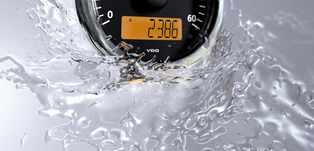
1 Marine Catalogue Viewline the new generation in instrumentation Navigation Instruments Tachometer & Tachourmeter Gauges for engine monitoring 1
2 Flavio Alessio 6 January


3 Page # VDO - Wempe Clocks 4 Viewline New Gauges 5 Viewline Instruments 15 Oceanlink Instruments 33 Sensors 34 3

4 Clocks & Weather Station With over 100 Years of experience in products dedicated to the marine world, VDO stands for quality. The new series of Black Ocean and White Ocean is a union of refined elegance. Dial Colour Part number Description CW Clock VDO Black Ocean Ø 100mm desk or wall mount, polished Stainless-Steel case Black CW Barometer VDO Black Ocean Ø 100mm desk or wall mount, polished Stainless-Steel case with grey pointers CW Hygrometer/Thermometer VDO Black Ocean Ø 100mm desk or wall mount, polished Stainless-Steel case with grey pointers CW Clock VDO White Dial Ocean Ø 100mm desk or wall mount, Satin Stainless-Steel case with White CW Barometer VDO White Dial Ocean Ø 100mm desk or wall mount, Satin Stainless-Steel CW Hygrometer/Thermometer VDO White Ocean Ø 100mm desk or wall mount, Satin Stainless -Steel case with black pointers 4

5 What s SUMLOG Ø 85mm Ø 110mm PITOT SPEEDO PITOT SPEEDO + TRIM WIND DIRECTION / SPEED CLOSE HAULED PITOT SPEEDO + FUEL DEPTH INDICATOR FUEL - PRESS - VOLT - TEMP 5
, the new Viewline tachometer and speedometer instruments have an additional digital display: Display size 37 mm x 11 mm Quick and")


 Individual function selection via external button Signal inputs.")
6 LCD display. As well as having an analogue indication (speed or engine revs), the new Viewline tachometer and speedometer instruments have an additional digital display: Display size 37 mm x 11 mm Quick and reliable retrieval of other data Optimum reading angle and representation on the display Display with speed or engine revs (option) Full backlight technology. The dials and pointers of all Viewline instruments feature full backlight technology: Optimum contrast and superb readability of the display when lit Attractive display appearance at night thanks to clearly structured dial design Combi and multifunction gauges*. Now, in addition to the tried and tested standard solutions, Viewline also offers OEMs the option of installing multifunction devices: 85 mm combi devices, analogue and / or digital representation of speedometer and tachometer signals (OEM solution) 110 mm multifunction devices, such as 4-in-1, 2-in-1* Integration of up to five display / warning lights (OEM solution) Further monitoring functions available on the LC display (e. g., battery, temperature, mileage indicator, etc.) Individual function selection via external button Signal inputs. Viewline offers the following options for the signal inputs: NMEA 0183 data input for all navigation instruments Standard tachometer and speedometer signals Second frequency input (option) Standard signals for engine monitoring and onboard power supply Signal inputs for special sensors (option) Up to five usable switching inputs for control / warning lights within the OEM version (option) Programmable displays. Viewline enables the user to use different setting and programming options: Basic setup via dip switches, external button or a PC software package Setup of various display functions via external button 6
7 Viewline Gauges Index Description Notes Diameter Page Conversion Table Oceanline to Viewline Gauges 8-9 Navigation Instruments Wind Direction/Speed - Depth Close Haul -Sumlog/Compass 80/85mm Tachourmeter Tachourmeter 3000, 4000, 5000, 6000 RPM 80/85mm Tachometer Tachometer 3000, 4000, 6000 RPM 80/85/52mm Synchroniser + / RPM 80/85mm 19 Temp Gauge Water, Oil, Transmission 52mm 20 Pyrometer Exhaust Temp 100ºC to 900ºC 52mm 21 Temp Gauge Outside Air Temp -25º to +50ºC 52mm 22 Pressure Gauge Turbo, Oil, Transmission 52mm Fuel Level Gauge Float Arm Type 52mm 25 Fuel Level Gauge Reed Switch Type 52mm 26 Fuel Level Gauge Tubular Type 52mm Fuel Level Gauge US Lever Type Ohms 52mm 29 Fresh Water Level Gauge Reed Switch Type 52mm 30 Waste/Grey Water Gauge 4-20 ma 52mm 31 Hourmeter Engine Hours 52mm 31 Voltmeter Battery Voltage 52mm 32 Ammeter Ampere Meter 60 A and +150 A 52mm 33 Trim Gauge Outboard Engine Trim 52mm 33 Rudder Angle Gauge Rudder Position 52/80/85mm 33 Clock Real Time Clock 52mm 33 Oceanlink J1939 & Analogue Master and Slaves 85/52mm 34 Sensors Various sensors Electrical Diagrams Gauges connection (power and signals) Gauges Accessories Bezels - Plugs & Terminals - Tools Fitting Instructions Conventional & flush mount fittings Calibration Instructions Speedo, Tachourmeter & Tachometer
8 Conversion Table Oceanline to Viewline Gauges Previous Oceanline Part number New Viewline Part number Gauge dial and Bezel Colour Function Voltage Ø Main Range N A2C BLACK Sumlog LCD (Speedo) 12/24V 85 50kn N A2C BLACK Trim 12/24V 52 Down N A2C BLACK Tacho 12/24V rpm N A2C BLACK Tacho 12/24V rpm N A2C WHITE Tachourmeter 12/24V rpm N A2C WHITE Tachourmeter 12/24V rpm N A2C WHITE Tachourmeter 12/24V rpm N A2C WHITE Tachourmeter 12/24V rpm N A2C BLACK Tachourmeter 12/24V rpm N A2C BLACK Tachourmeter 12/24V rpm N A2C BLACK Tachourmeter 12/24V rpm N A2C BLACK Tachourmeter 12/24V rpm N & N A2C WHITE Tacho 12/24V rpm N & N A2C WHITE Tacho 12/24V rpm N & N A2C WHITE Tacho 12/24V rpm N & N A2C BLACK Tacho 12/24V rpm N & N A2C BLACK Tacho 12/24V rpm N & N A2C BLACK Tacho 12/24V rpm N & N A2C WHITE Press Turbo 12/24V 52 2bar N & N A2C WHITE Press Oil 12/24V 52 5bar N & N A2C WHITE Press Oil 12/24V 52 10bar N & N A2C WHITE Press Oil 12/24V 52 25bar N & N A2C WHITE Press Oil 12/24V 52 30bar N & N A2C BLACK Press 12/24V 52 2bar N & N A2C BLACK Press Oil 12/24V 52 5bar N & N A2C BLACK Press Oil 12/24V 52 10bar N & N A2C BLACK Press Trans 12/24V 52 25bar N & N A2C BLACK Press Trans 12/24V 52 30bar N & N A2C WHITE Level Fuel 12/24V 52 1/1 N & N A2C BLACK Level Fuel 12/24V 52 1/1 N & N A2C WHITE Level Fuel 12/24V 52 1/1 N & N A2C BLACK Level Fuel 12/24V 52 1/1 8
9 Conversion Table Previous Oceanline Part number Oceanline to Viewline Gauges New Viewline Part number Gauge colour dial/bezel Main Function Voltage Ø Range Scale FSD N A2C WHITE Level Freshwater 12/24V 52 1/1 20mA N A2C BLACK Level Freshwater 12/24V 52 1/1 20mA N A2C WHITE Level Waste water 12/24V 52 1/1 20mA N A2C BLACK Level 12/24V 52 1/1 20mA N A2C WHITE Level Freshwater 12/24V 52 F S LT-EU N & N A2C BLACK Level Freshwater 12/24V 52 1/1 S LT-EU N A2C WHITE Pyrometer 12/24V C 37mV N A2C BLACK Pyrometer 12/24V C 37mV N A2C BLACK Pyrometer 12/24V F 37mV N A2C BLACK Temp Outside 12/24V C 2kOhm N A2C WHITE Temp Outside 12/24V C 2kOhm N & N A2C WHITE Temp Water 12/24V C D EU N A2C WHITE Temp Oil 12/24V C D EU N & N A2C BLACK Temp water 12/24V C D EU N & N A2C BLACK Temp Oil 12/24V C D EU N A2C WHITE Amp ext. Shunt 12/24V A 60mV N A2C BLACK Amp ext. Shunt 12/24V A 60mV N A2C BLACK Amp ext. Shunt 12/24V A 60mV N A2C WHITE Volt 12V S N A2C BLACK Volt 12V 52 1/1 S N A2C WHITE Volt 24V 52 32V S N A2C BLACK Volt 24V 52 32V S N A2C WHITE Hourmeter 12/24V 52 N A2C BLACK Hourmeter 12/24V 52 N & N A2C WHITE Rudder angle 12/24V Stb S N A2C WHITE Rudder angle 12/24V S N A2C BLACK Rudder angle 12/24V S N & N A2C BLACK Rudder angle 12/24V Stb S N A2C WHITE Clock 12V 52 S N A2C WHITE Clock 24V 52 S N A2C BLACK Clock 12V 52 S N A2C BLACK Clock 24V 52 S 9

10 10
11 Introducing VDO Viewline Our engineers started with a clean sheet of paper and a worldwide view to create an instrument line like no other in today's market. Their goal to create an instrument with flexibility, class and integrity something you've come to expect from VDO. It begins with a fresh style and three choices of instrument sizes 100mm, 85mm and 52mm. For styling, you have a choice of dial face colors of Black or White. Next we added three choices of bezel styles along with two choices of bezel colors, white, black and chrome. To complete your choices we give you three choices of instrument sizes 100mm, 85mm and 52mm giving you more flexibility than ever to create the instrument you are looking for. They did not stop with just a pretty face, next they added integrity. With the use of fully sealed dual lens, lifetime LED lighting and warning indicators assure you that Viewline can withstand even open cab environments easily. Whether you are looking for standard or customized products, you are truly getting "more bang for your buck" with Viewline. The VDO Heritage: Reliability, durability and accuracy. Reliability Durability IP67 water resistance means, that no matter how wet it gets, our gauges keep on working. Anti-corrosion materials mean no oxidation or rust will develop Viewline will continue to work and look like new. Accuracy CE certification. GL registered. UL94 flame resistance. Tested to 25 G continuous vibration and 100 G shock. VDO patented stepper motors and resistive movements. 100% LED warning lights and telltales for long service life. OEM derived technology in every instrument. 11

.")
12 Viewline Gauges Viewline is the new standardised instrument platform for pleasure boats and yachts. With modular solutions in three housing variations, we supply more functions, more flexible installation and design options as well as space-saving combi instruments something unique in this sector. All Viewline instruments can be conveniently mounted in the instrument panel. Here, it is possible to use the modular bezels for installation as well as integrating the instruments flat without the bezels (flush installation). This allows maximum flexibility in cockpit customisation and numerous design variants. 12
 is programmable to OEM-specified function. 4. Single cavity connectors reduce wiring installation time. 5. Reverse polarity and over voltage protection virtually eliminate the possibility of installation failures.")
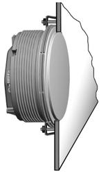
13 Viewline Gauges VDO Spin-Lok mounting 1. Spin-Lok mounting a VDO innovation developed to safeguard against mounting panel warping and makes fast installation. 2. Single PCB increases reliability and minimizes instrument depth. 3. Built-in LED warning indicator (up to 5) is programmable to OEM-specified function. 4. Single cavity connectors reduce wiring installation time. 5. Reverse polarity and over voltage protection virtually eliminate the possibility of installation failures. 6. VDO is one of the few companies in the world to design, patent and manufacture stepper motors and resistive movements. 7. Corrosion-free and flame retardant materials comply with manufacturer's latest specifications. 8. Laser welded lenses ensure the highest level of protection against water intrusion. 9. Dual domed lenses eliminate fogging another VDO innovation. 10. LED lit pointers and through dial lighting" minimize current consumption while optimizing nighttime viewing. " 11. Detail finish ring enhances the overall appearance of finished instrument a VDO exclusive. 12. Designed to withstand continuous 25 G vibrations and 100 G single shock, to ensure maximum reliability of each instrument. 13. Large, multifunction backlit LCD provides easy readout of programmed functions. 14. Customer installed bezels with nine style choices allow for greater styling differentiation between product lines. 13


14 Viewline Gauges Benefiting in the long-term from new technologies In developing the Viewline instrumentation, we have paid attention to the requirements of manufacturers. With Viewline, we have created a platform-wide standard with which we offer maximum freedom in respect of cockpit design. Highly visible LED warning and indicator lights Viewline instruments are fitted with highly visible, high intensity LED warning and indicator lights. They ensure that critical operating conditions can be quickly and safely detected. Clip-on bezel The modular bezel concept offers design flexibility in the layout of instrument panels. Three attractive design variants in black, white or chrome perfectly complement any boat s interior. Furthermore, bezels are available in flat, round and triangular versions. All available bezels can be combined with all devices. 14

15 Viewline Gauges Viewline Black Viewline White 15

")
16 Navigation Instruments Wind Direction / Speed Ø 80/85 mm Colour Dial/ Bezel Range Voltage A2C Black 0-180º BB/SB 12/24V A2C White 0-180º BB/SB 12/24V Apparent Wind - Maximum Wind Speed Atmospheric Air Pressure - Ambient Temperature - Clock Close Haul Ø 80/85 mm Colour Dial/ Bezel Range Voltage A2C Black 0-60º BB/SB 12/24V A2C White 0-60º BB/SB 12/24V Apparent Wind - Maximum Wind Speed Atmospheric Air Pressure - Ambient Temperature - Clock Voltmeter (when connected to an NMEA0183 PB100 or PB200 Sensor) Note: BB = Port SB=Star Board Depth Ø 80/85 mm Colour Dial/ Bezel Range Voltage A2C Black /24V A2C White /24V Water Temperature - Depth - Shallow Water Alarm Voltmeter - Clock (when connected to an NMEA0183 Depth Sensor) Sumlog - Compass Colour Dial/ Bezel Ø 80/85 mm Range Voltage Applicable Signal A2C Black 12 Kn 12/24V NMEA 0183 Water Temperature - Depth - Compass Course - Course Over Ground - GPS Time - Steering Aid - Voltmeter - Trip & Distance (when connected to an active NMEA0183 from a Paddle Wheel Sensor - GPS or Compass Sensor) A2C Black 30 Kn 12/24V NMEA 0183 A2C Black 50 Kn 12/24V NMEA 0183 A2C Black 60 MPH 12/24V NMEA 0183 A2C White 12 Kn 12/24V NMEA 0183 A2C White 30 Kn 12/24V NMEA 0183 A2C White 50 Kn 12/24V NMEA 0183 A2C White 60 MPH 12/24V NMEA

17 Sumlog & Tachourmeter Sumlog (standard) Colour Dial/ Bezel Ø 80/85 mm Range Voltage Smart Transducer A2C Black 0-12 Kn 12/24V See below A2C White 0-12 Kn 12/24V See below A2C Black 0-50 Kn 12/24V See below A2C White 0-50 Kn 12/24V See below B Speed Total & Trip Distance Depth Sea Water Temperature Clock Voltmeter External Trip-reset Button External Mode Button A Transducer : Speed - Depth - Sea Water Temp Range Description Cable Length Connector Kn Blue NMEA Transom Kit 10 m White NMEA A Red + 12/24V Black/Shield Negative X Kn Transom Kit 10 m Blue NMEA White NMEA Red + 12/24V Black/Shield Negative X Kn Blue NMEA Through-Hull Kit 10 m White NMEA B Red + 12/24V Black/Shield Negative Through-Hull Kit Transom Kit A2C Loom 0.3 m Connection between Transducer p/n X or p/ n X and Sumlog head. Tachourmeter Colour Dial/ Bezel Ø 80/85 mm Range Voltage Applicable Signal Engine Speed (RPM) Total & Trip Hours Clock Voltmeter External Trip-reset Button External Mode Button Programmable External Alarm A2C Black RPM A2C Black RPM A2C Black RPM A2C Black RPM A2C Black RPM A2C Black RPM 12/24V 12/24V 12/24V 12/24V 12/24V 12/24V Alternator Ignition Coil Generator Inductive Alternator Ignition Coil Generator Inductive Alternator Ignition Coil Generator Inductive Alternator Ignition Coil Generator Inductive Alternator Ignition Coil Generator Inductive Alternator Ignition Coil Generator Inductive Note: For all 270º meter movement deflection Viewline gauges calibration, use Viewline Software adaptor cable & Software p/n A2C
 Total & Trip Hours Clock")
18 Tachourmeter & Tachometer Tachourmeter Colour Dial/ Bezel Ø 80/85 mm Range Voltage Applicable Signal A2C White RPM 12/24V Alternator, Ignition Coil Generator, Inductive A2C White RPM 12/24V A2C White RPM 12/24V Alternator Ignition Coil Generator Inductive Alternator, Ignition Coil Generator, Inductive Engine Speed (RPM) Total & Trip Hours Clock Voltmeter External Trip-reset Button External Mode Button Programmable External Alarm A2C White RPM 12/24V Alternator Ignition Coil Generator Inductive Tachometer Colour Dial/ Bezel Ø 52 mm Range Voltage Applicable Signal A2C Black RPM 12/24V Alternator Ignition Coil (Note: Alternator signal calibration via software, only). A2C Black RPM 12/24V Alternator Ignition Coil (Note: Alternator signal calibration via software, only). A2C Black RPM 12/24V Alternator Ignition Coil (Note: Alternator signal calibration via software, only). A2C White RPM 12/24V Alternator Ignition Coil (Note: Alternator signal calibration via software, only). A2C White RPM 12/24V Alternator Ignition Coil (Note: Alternator signal calibration via software, only). Engine Speed (RPM) A2C White RPM 12/24V Alternator Ignition Coil (Note: Alternator signal calibration via software, only). 18

 12/24V Alternator Ignition Coil (Note: Alternator signal calibration via software, Contact a VDO Service Agent for assistance) 12/24V Alternator Ignition")
19 Tachometer Tachometer Colour Dial/ Bezel Ø 80/85 mm Range Voltage Applicable Signal Engine Speed (RPM) Programmable Alarm (Software) A2C Black RPM A2C Black RPM A2C Black RPM A2C White RPM A2C White RPM A2C White RPM 12/24V Alternator Ignition Coil (Note: Alternator signal calibration via software, only. Contact a VDO Service Agent for assistance) 12/24V Alternator Ignition Coil (Note: Alternator signal calibration via software, only. Contact a VDO Service Agent for assistance) 12/24V Alternator Ignition Coil (Note: Alternator signal calibration via software, only. Contact a VDO Service Agent for assistance) 12/24V Alternator Ignition Coil (Note: Alternator signal calibration via software, only. Contact a VDO Service Agent for assistance) 12/24V Alternator Ignition Coil (Note: Alternator signal calibration via software, only. Contact a VDO Service Agent for assistance) 12/24V Alternator Ignition Coil (Note: Alternator signal calibration via software, only. Contact a VDO Service Agent for assistance) Synchroniser Tachometer Colour Dial/ Bezel Ø 80/85 mm Range Voltage Applicable Signal Differential Engine Speed (RPM) A2C Black +/ RPM A2C White +/ RPM 12/24V Alternator Ignition Coil Generator Inductive 12/24V Alternator Ignition Coil Generator Inductive 19
20 Temperature Temperature Gauge Water Colour Dial/ Bezel Ø 52 mm Range Voltage Ohms Range A2C Black C (250F) 12/24V Ohms 38.6 Ohms = 100C A2C White C (250F) 12V/24V Ohms 38.6 Ohms = 100C Temperature Sender Water Range Thread size Connector K N K N N C C (250F) C (250F) C (250F) C (250F) C (250F) C (250F) M14x1.5 M18x1.5 1/2-14NPTF 1/4-18NPTF 3/8-18NPTF 5/8-18UNF 2A 2 spade terminals 2 spade terminals 2 spade terminals 2 spade terminals 2 spade terminals 2 spade terminals Note: For single terminals (earth return) or dual station senders, refer appendix on page Temperature Gauge Engine Colour Dial/ Bezel Ø 52 mm Range Voltage Ohms Range A2C Black C (300F) 12V/24V Ohms 62.2 Ohms = 100C A2C White C (300F) 12V/24V Ohms 62.2 Ohms = 100C Temperature Sender Engine Range Thread size Connector K N C (300F) C (300F) M14x1.5 1/4-18NPTF 2 spade terminals 2 spade terminals Note: For single terminals (earth return) or dual station senders, refer appendix on page 38-39
 12/24V 4.04-37.5 mv 12/24V 4.04-37.5 mv 12/24V 4.04-37.5 mv 12/24V 4.04-37.5 mv Thermocouple K Type Kit (no gauge) Description Range Terminals 320.")
21 Pyrometer Pyrometer Gauge - Colour Dial/ Bezel Ø 52 mm Range Voltage mv Range A2C Black C (1650F) A2C White C (1650F) A2C Black F (900C) A2C White F (900C) 12/24V mv 12/24V mv 12/24V mv 12/24V mv Thermocouple K Type Kit (no gauge) Description Range Terminals Thermocouple Probe C (1650F) Red = Negative Yellow = Positive Compensating Cable 5 metres White = Negative Blue = Positive or Red = Negative Brown = Positive K Type thermocouple Calibration Chart Degrees Celsius Probe Voltage (mv) Celsius to Fahrenheit Conversion Chart Install the sensor in the exhaust pipe near the elbow flange. Maximum adjustment depth up to the middle of exhaust pipe: 60 mm. Mount the bushing centrally and weld on. The weld must form a tight seal. Degrees Celsius Degrees Fahrenheit

 1/8-27NPTF 2 x M4 Screws 360081032011C 0-2 Bar (28 Psi) M12x1.")
22 Outside Temp & Turbo Pressure Outside Air Temperature Colour Dial Bezel Range Voltage Ø 52 mm Ohms A2C Black -25to+50C 12/24V 0 C = 4082 Ohms A2C White -25to+50C 12/24V 0 C = 4082 Ohms Temperature Sender Air Range Cable Length Wires C -25to+50C L = 4500mm Green Signal Brown Negative Pressure Gauge Turbo 2 Bar Colour Dial/ Bezel Range Voltage Ohms Range A2C Black 0-2 Bar (28 Psi) A2C White 0-2 Bar (28 Psi) 12/24V Ohms 0-2 Bar 12/24V Ohms 0-2 Bar Pressure Sender 2 Bar Range Thread size Connector C 0-2 Bar (28 Psi) 1/8-27NPTF 2 x M4 Screws C 0-2 Bar (28 Psi) M12x1.5 2 x M4 Screws Note: For single terminals (earth return) or dual station senders, refer to pages
23 Oil Pressure Pressure Gauge Engine Oil Ø 52 mm Colour Dial Bezel Range Voltage Ohms Range A2C Black 0-5 Bar (72 Psi) A2C White 0-5 Bar (72 Psi) 12/24V 12/24V 0 Bar = 10 5 Bar = Bar = 10 5 Bar = 183 Pressure Sender Engine Oil Range Thread size Connector C C 0-5 Bar (72 Psi) 0-5 Bar (72 Psi) M10x1 1/8-27NPTF 2 Screw terminals 2 Screw terminals Note: For single terminals (earth return) or dual station senders, refer to pages Pressure Gauge Engine Oil Colour Dial Bezel Range A2C Black 0-10 Bar (150 Psi) A2C White 0-10 Bar (150 Psi) Voltage 12/24V 12/24V Ø 52 mm Ohms Range 0 Bar = Bar = Bar = Bar = 183 Pressure Sender Engine Oil Range Thread size Connector C C C 0-10 Bar (150 Psi) 0-10 Bar (150 Psi) 0-10 Bar (150 Psi) M10x1 M14x1.5 1/8-27NPTF 2 Screw terminals 2 Screw terminals 2 Screw terminals Note: For single terminals (earth return) or dual station senders, refer to pages
24 Transmission Pressure Pressure Gauge Transmission Colour Dial Bezel Range Voltage Ø 52 mm Ohms Range A2C Black 0-25 Bar (400 Psi) A2C White 0-25 Bar (400 Psi) 12/24V 12/24V 0 Bar = Bar = Bar = Bar = 183 Pressure Sender Transmission Range Thread size Connector C C C 0-25 Bar (400 Psi) 0-25 Bar (400 Psi) 0-25 Bar (400 Psi) M14x1.5 1/8-27NPTF 3/8-18NPTF 2 Screw terminals 2 Screw terminals 2 Screw terminals Note: For single terminals (earth return) or dual station senders, refer to pages Pressure Gauge Transmission Colour Dial Bezel Range Voltage Ø 52 mm Ohms Range A2C Black 0-30 Bar (435 Psi) 12/24V 0 Bar = Bar = 183 A2C White 0-30 Bar (435 Psi) 12/24V 0 Bar = Bar = 183 Pressure Sender Transmission Range Thread size Connector C C C 0-30Bar (435 Psi) 0-30Bar (435 Psi) 0-30 Bar (435 Psi) M14x1.5 1/8-27NPTF 3/8-18NPTF 2 Screw terminals 2 Screw terminals 2 Screw terminals Note: For single terminals (earth return) or dual station senders, refer to pages *For 30 Bar pressure sender s range, use 25 Bar senders 24


25 Fuel Fuel Gauge Ø 52 mm Colour Dial Bezel Range Voltage Ohms Range A2C Black /24V A2C White /24V Empty = 3 Full = 180 Empty = 3 Full = 180 Sender Float Arm - Fuel Pitch 54 mm Range Notes Terminal C Ohms Adjustable mm Spade x C N Insulated return N Ohms Adjustable mm A2C Ohms Sender with low fuel warning switch. Adjustable mm Spade x2 Spade x3 A2C Ohms Arm Type Fuel Sender Adjustable mm Spade x2 A2C Ohms Sender with low fuel warning switch. Adjustable mm Spade x3 A2C595101xx Insulated return A2C Ohms Arm Type Fuel Sender Adjustable mm A2C Ohms Sender with low fuel warning switch. Adjustable mm Spade x2 Spade x3 A2C Ohms Arm Type Fuel Sender Adjustable mm Spade x2 CTA0200 Note: Use adaptor plate p/n CTA0200 when installing the five holes sender s plate on to 6 holes applications. 25
 Sender Reed Switch - Fuel Pitch 54 mm Range E - F L = length 220.150-180 3-180 Ohms 150 mm * 220.")

26 Fuel Fuel Gauge Ø 52 mm Colour Dial Bezel Range Voltage Ohms Range A2C Black /24V A2C White /24V Empty = 3 Full = 180 Empty = 3 Full = 180 Note: All Reed Switch senders on the list below have a Low Fuel Warning switch, except the 150 & 180 mm length (marked *) Sender Reed Switch - Fuel Pitch 54 mm Range E - F L = length Ohms 150 mm * Ohms 180 mm * Ohms 230 mm Ohms 250 mm Ohms 260 mm Ohms 270 mm Ohms 300 mm Ohms 320 mm Ohms 330 mm Ohms 350 mm Ohms 600 mm Ohms 660 mm CTA0200 Item # Qty Description Material 1 1 Sensor Head S/Steel Reed Sw Tube S/Steel Float 32x32mm Acrylon NBR 4 1 Bottom plug S/Steel Reed Sw assy NBR Rubber 7 1 Cover Alum 8 1 Gasket 68x2mm NBR 60 Note: Use adaptor plate p/n CTA0200 when installing the five holes sender s plate on to 6 holes applications. 26


27 Fuel Fuel Gauge Tubular Type Colour Dial Bezel Range Voltage A2C Black 0-1/1 12/24V A2C White 0-1/1 12/24V Ohms Range Empty = 110 / 50 Full = 2 Empty = 110 / 50 Full = 2 Sender Tubular Type - Fuel Pitch 54 mm Sender Part No. Length Sender Part No. Length G 150mm G 320mm G 160mm G 330mm G 170mm G 340mm G 180mm G 350mm G 190mm G 360mm G 200mm G 370mm G 210mm G 380mm G 220mm G 390mm G 230mm G 400mm G 240mm G 450mm G 250mm G 500mm G 260mm G 550mm G 270mm G 600mm G 280mm G 650mm G 290mm G 700mm G 300mm G 750mm G 310mm G 800mm 27

28 Fuel Fuel Gauge Tubular Type Colour Dial Bezel Range Voltage Ohms Range A2C Black 0-1/1 12/24V A2C White 0-1/1 12/24V Empty = 110 / 50 Full = 2 Empty = 110 / 50 Full = 2 Sender Tubular Type - Fuel Pitch 80 mm Accessories: p/n Welding Flange Ø80mm p/n Gasket Cork Ø80mm Sender Part No. Length Sender Part No. Length X mm X mm X mm X mm X mm X mm X mm X mm X mm X mm X mm X mm X mm X mm X mm X mm X mm X mm X mm X mm X mm X mm X mm
29 Fuel Gauge - US Senders Fuel Gauge (US Application) Colour Dial / Bezel Range Voltage Ø 52 mm Ohms Range A2C Black E -1/2 - F 12/24V A2C White E -1/2 - F 12/24V Empty = 5 Full = 90 Empty = 5 Full = 90 A2C Black E -1/2 - F 12/24V Empty= 240 Full = 33 A2C White E -1/2 - F 12/24V Empty= 240 Full = 33 Lever Fuel Sensor - without low fuel alarm Ohms Range Adjustable Pitch Ø mm 54 mm mm 54 mm Lever Fuel Sensor - with low fuel alarm Ohms Range Adjustable Pitch Ø A2C mm 54 mm A2C mm 54 mm Lever Fuel Sensor - without low fuel alarm Ohms Range Ohms Range Pitch Ø A2C mm 54 mm A2C mm 54 mm Tank Sender Accessories CTA0200 Part No. Description. N Flange Kit Bolt Circle Ø54mm Bolt Circle Ø54mm G Bolt Circle Ø80mm CTA0200 Six to five holes conversion plate 29

30 Fresh Water Fresh Water Level Gauge Colour Dial Bezel Range Voltage A2C Black 0-1/1 12/24V A2C White 0-1/1 12/24V Ø 52 mm Range Empty = 4 ma Full = 20 ma Empty = 4 ma Full = 20 ma Fresh Water Sender 4-20 ma Range E - F Adjustable length Terminal N % mm Water-Proof Plug N % mm Water-Proof Plug N % mm Water-Proof Plug X Tank unit flange with Gasket Fresh Water Level Gauge Colour Dial Bezel Range Voltage A2C Black 0-1/1 12/24V A2C White 0-1/1 12/24V Ø 52 mm Range Empty = 3 Ohms Full = 180 Ohms Empty = 3 Ohms Full = 180 Ohms Sender Reed Switch - Water Pitch 54 mm Range E - F L = length Terminal Ohms 150 mm Water-Proof Plug Ohms 180 mm Water-Proof Plug Ohms 230 mm Water-Proof Plug Ohms 260 mm Water-Proof Plug Ohms 270 mm Water-Proof Plug Ohms 300 mm Water-Proof Plug Ohms 320 mm Water-Proof Plug Ohms 330 mm Water-Proof Plug Ohms 600 mm Water-Proof Plug Ohms 660 mm Water-Proof Plug 30


 Thread Size Terminals Picture Switch Contact 230.050 0.")
31 Waste Water & Hourmeter Waste Water Level Gauge Colour Dial Bezel Range Voltage A2C Black 0-1/1 12/24V A2C White 0-1/1 12/24V Ø 52 mm Range Empty = 4 ma Full = 20 ma Empty = 4 ma Full = 20 ma Waste Water Sender Range E - F Adjustable length Terminal N N N Empty = 4 ma Full = 20 ma Empty = 4 ma Full = 20 ma Empty = 4 ma Full = 20 ma mm Water-Proof Plug mm Water-Proof Plug mm Water-Proof Plug Accessory X Description Tank unit flange with Gasket Hourmeter Colour Dial/ Bezel Light Voltage A2C Black Yes A2C White Yes 12/24V 12/24V Pressure Switch - Heavy Duty Part Number Switch Point Bar (Psi) Thread Size Terminals Picture Switch Contact Bar (7) Fixed 1/8-27NPTF Screw x 2 Insulated Return A N/O Raising Pressure 31


32 Volt & Ammeter Voltmeter Ø 52 mm Colour Dial / Bezel Range Voltage A2C Black 8-16V 12V A2C White 8-16V 12V A2C Black 18-32V 24V A2C White 18-32V 24V Ammeter Gauge with external shunt Ø 52 mm Colour Dial / Bezel Range Voltage A2C Black 60A 12/24V A2C White 60A 12/24V A2C Black 150A 12/24V A2C White 150A 12/24V Note: Gauge does not include Current Sensor or Loom Ammeter Shunt Range / Description Voltage UK-UE A 12/24V UK-UE A 12/24V UK-UE-184 UK-UE-188 Shunt Harness Universal Mounting Bracket Kit SENSOR Specs Sensor Type: Open loop Hall-Effect Linearity: 1.5% Supply Voltage Range: 12/24V Current Consumption: 8.1 ma max Output to Gauge: mv Operating Temp: 40 C to C Storage Temp: 40 C to C Aperture size: mm Weight: Kg Connector: Packard sealed Metri-Pak 150 Note: Mating plug not supplied with sensor 32


33 Trim & Rudder Angle Trim Gauge Colour Dial/ Bezel Range Ø 52 mm Voltage A2C Black Bravo Drive 12/24V Note: Trim sensor for the Bravo drive is a Mercury product. A2C White Bravo Drive 12/24V Rudder Angle Indicator Rudder Angle Indicator Colour Dial/ Bezel Colour Dial/ Bezel Range Range Ø 52 mm Voltage A2C Black 40º Stb 12/24V (for 24V with dropping voltage resistor p/n A2C A2C White 40º Stb 12/24V (for 24V with dropping voltage resistor p/n A2C Ø 80/85 mm Voltage A2C Black +45º 12V A2C White +45º 12V Rudder Angle Sender Voltage Note D Single Station 12/24V Sender suitable for 52 and 85mm gauges D Dual Station 12/24V Dual station sender has a D market on the body Clock Ø 52 mm Colour Dial/ Bezel Range Voltage A2C Black 12h 12V A2C White 12h 12V A2C Black 12h 24V A2C White 12h 24V 33

34 Oceanlink Engine Monitoring Master SAE J1939 Ø 80/85 mm Part Number Colour Dial/ Bezel 34 Description Range Voltage N Black Master Gauge /24V N Black Master Gauge /24V N White Master Gauge /24V N White Master Gauge /24V Engine Monitoring Slave SAE J1939 Ø 52 mm Part Number Colour Dial/ Bezel Description Range Voltage N Black Gearbox oil pressure gauge 25 bar 12/24V N Black Engine oil pressure gauge 10 bar 12/24V N Black Boost pressure gauge 3 bar 12/24V N Black Engine oil pressure gauge 150 psi 12/24V N Black Gearbox pressure gauge 360 psi 12/24V N Black Fuel tank gauge 0-4/4 12/24V N Black Engine load 0-100% 12/24V N Black Fuel flow gauge 80 l/h 12/24V N Black Engine oil temperature gauge C 12/24V N Black Engine coolant temperature C 12/24V N Black Gearbox oil temperature C 12/24V N Black Exhaust gas temperature C 12/24V N Black Gearbox oil temperature F 12/24V N Black Exhaust gas temperature F 12/24V N Black Exhaust gas temperature, Turbine A F 12/24V N Black Exhaust gas temperature, Turbine B F 12/24V N Black Engine coolant temperature F 12/24V N Black Exhaust gas temperature, Turbine A C 12/24V N Black Exhaust gas temperature, Turbine B C 12/24V N Black Voltmeter V 24V N Black Voltmeter 8-16 V 12V N Black Engine oil temperature F 12/24V N White Gearbox oil pressure gauge 25bar / 360psi 12/24V N White Engine oil pressure gauge 10bar / 145psi 12/24V N White Fuel tank gauge 0-4/4 12/24V N White Engine oil temperature gauge 150 C / /24V N White Engine coolant temperature gauge 120 C / 250 F 12/24V N White Voltmeter V 24V N White Voltmeter 8-16 V 12V
35 Sensors Level Switch Low Level Warning Switch - Oil & Diesel Installation from Contact mm L Above Above Above Below Below Below Below 120 Switch Load Thread Size M22x1.5 M22x1.5 M22x1.5 M22x1.5 M22x1.5 M22x1.5 M22x Below 150 3W M22x1.5 2W 2W 3W 3W 2W 2W 3W Voltage 24V 12V 24V 24V 12V 12V 24V 24V The difference between L and S is 25mm 35


36 Sensors Level Switch Oil Level Warning Switch Warning Contact Stop Above Stop Below Cable Length hw hw min Ao Au L ± ± ±2 920 Plug configuration Technical Data 36
37 Sensors Pressure Earth Return Insulated Return Earth Return Switch /Sender G G Negative Warning G Contact G WK Insulated Return Switch /Sender Negative M Earth A B C D Warning Contact WK Pressure Sender - Oil / Air Range Bar (Psi) Pressure Sender - Oil / Air Range Bar (Psi) Single Station Thread Size Single Station Thread Size Switch Point Bar (Psi) Switch Point Bar (Psi) Picture Picture Ohms Range C 0-2 Bar (75) 1/8-27NPTF --- B C 0-2 Bar (75) M12x B Ohms Range Bar (75) 1/8-27NPTF --- A Bar (75) 1/4-18NPTF --- A Bar (75) 1/8-28BSP --- A C 0-5 Bar (75) 1/8-27NPTF --- B C 0-5 Bar (75) M10x1 --- B K 0-5 Bar (75) M10x Bar (3.5) C K 0-5 Bar (75) M10x1 0.5 Bar (7) C K 0-5 Bar (75) M14x Bar (7) C K 0-5 Bar (75) 1/8-27NPTF 0.5 Bar (7) C C 0-5 Bar (75) M10x1 0.6 bar (8.5) C C 0-5 Bar (75) 1/8-27NPTF 1.4 Bar (11.5) C C 0-5 Bar (75) 1/8-27NPTF 11.5 Psi D C 0-80 Psi 1/8-27NPTF 10 Psi D Pressure Sender - Oil / Air Range Bar (Psi) Dual Station Thread Size Switch Point Bar (Psi) Picture Ohms Range K 0-5 Bar (75) 1/8-27NPTF --- B K 0-10 Bar (150) 1/8-27NPTF --- B K 0-10 Bar (150) 1/8-27NPTF --- A K 0-25 Bar (350) 1/8-27NPTF --- B C 0-25 Bar (350) 1/8-27NPTF --- A
 Thread Size Single Station Switch Point Bar (Psi) Picture Ohms Range 360081030009K 0-10 Bar (150) M10x1 0.")
38 Sensors Pressure Earth Return Insulated Return Earth Return Switch /Sender G G Negative G Warning Contact WK Insulated Return Switch /Sender G Negative M Earth A B C D Warning Contact WK Pressure Sender/Switch - Oil / Air Range Bar (Psi) Thread Size Single Station Switch Point Bar (Psi) Picture Ohms Range K 0-10 Bar (150) M10x1 0.5 Bar (7) C C 0-10 Bar (150) M12x Bar (7) C C 0-10 Bar (150) 1/8-27NPTF 0.5 Bar (7) C C 0-10 Bar (150) M10x Bar (10.7) C C 0-10 Bar (150) 1/8-27NPTF 0.8 Bar (11.5) C C 0-10 Bar (150) M10x1 0.9 Bar (12) C Bar (150) 1/8-27NPTF 0.8 Bar (11.5) D Pressure Sender - Oil / Air Single Station Bar (400) 1/8-27NPTF B A B C Pressure Switches - Heavy Duty Switch Point Bar (Psi) Thread Size Bar (7) Fixed 1/8-27NPTF Screw x 2 Insulated Return Bar (7) Fixed 1/8-27NPTF Screw x 2 Insulated Return Bar (64) Fixed M10 x 1 Screw x 2 Insulated Return Bar (64) Fixed 1/8-27NPTF Screw x 2 Insulated Return Bar (10) Fixed 1/8-27NPTF Screw x 1 Earth Return Bar (15) Fixed 1/8-27NPTF Screw x 2 Insulated Return Bar (7) Fixed 1/8-27NPTF Screw x 2 Insulated Return Psi Adjustable 1/8-27NPTF Screw x 2 Insulated Return Psi Adjustable 1/8-27NPTF Screw x 2 Insulated Return Terminals Picture Switch Contact B B B B A B B C C N/C Falling Pressure N/C Falling Pressure N/C Falling Pressure N/C Falling Pressure N/C Falling Pressure N/C Falling Pressure N/O Falling Pressure N/C Falling Pressure N/C Falling Pressure 38


39 Sensors Temperature A B C D E Temp Senders Switch Point Thread Size Term Deg C Body Length C Ohms K M14x1.5 A 29 mm ± N M16x1.5 A 29 mm ± K M18x1.5 A 29 mm ± K /2-14 NPTF A 29 mm ± N /4-18 NPTF A 29 mm ± N /8-18 NPTF A 29 mm ± N /8-18 UNF-3A A 29 mm ± K M14x1.5 D 29 mm ± N M18x1.5 D 29 mm ± K /2-14 NPTF D 29 mm ± N /4-18 NPTF D 29 mm ± N /8-18 NPTF D 29 mm ± C /8-18 UNF-3A D 29 mm ± C /4-18 NPTF D 29 mm ± 2.7 Temp Senders & Switch Deg C D 90±3 C M14x1.5 E 40 mm ± D 96±3 C M14x1.5 E 40 mm ± D 110±3 C M14x1.5 E 40 mm ± D 95±3 C 5/8-18 NF-3 E 40 mm ± D 98±3 C 5/8-18 NF-3 E 40 mm ± D 100±3 C 5/8-18 NF-3 E 40 mm ± D 95±3 C 1/2-14 NPTF E 40 mm ± D 106±3 C M14x1.5 E 40 mm ± D 105±3 C M14x1.5 F 40 mm ± ±3 C 1/2-14 NPTF E 40 mm ± 5.3 F Temp Senders Switch Point Thread Size Term Deg C Body Length C Ohms D M10x1.5 D 29 mm ± N M14x1.5 D 29 mm ± N /4-18 NPTF D 29 mm ±
40 Sensors A B C D Temperature Temp Switch Switch Point 3 Watts Normally Open Contact - Break 5 below Sw point Thread Size Term Body Length L Max Temp D 35±3 C M14x1.5 A 29 mm D 40±3 C M14x1.5 D 29 mm D 55±3 C M14x1.5 A 29 mm D 85±3 C M14x1.5 A 29 mm D 95±3 C M14x1.5 A 29 mm D 97±3 C M14x1.5 A 29 mm D 98±3 C 5/8-18 UNF-2A A 29 mm D 100±3 C M14x1.5 A 29 mm D 103±3 C 1/2-14 NPTF A 29 mm D 110±3 C M14x1.5 A 29 mm D 120±3 C M14x1.5 A 29 mm D 130±3 C M14x1.5 A 29 mm D 140±10 C M14x1.5 A 29 mm D 150±5 C M10x1.5 B 38.5 mm D 170±5 C M10x1.5 C 38.5 mm D 185±5 C M10x1.5 C 38.5 mm D 195±10 C M10x1.5 C 38.5 mm Ø mm E F Temp Switch 100 Watts Normally Open Contact - Break 5 below Sw point Switch Point Thread Size Term Body Length L Max Temp X ±3 C M14x1.5 E 35.5 mm X ±3 C M18x1.5 E 35.5 mm X ±3 C M18x1.5 E 35.5 mm X ±3 C M18x1.5 E 35.5 mm X ±3 C M18x1.5 E 35.5 mm X ±3 C 1/2-14 NPTF E 43.5 mm X ±3 C M14x1.5 E 35.5 mm X ±3 C M22x1.5 F 35.5 mm X ±3 C M18x1.5 E 35.5 mm X ±3 C M18x1.5 E 35.5 mm Ø mm 40


41 Sensors RPM Inductive Pic Thread Size L1 mm L2 mm L3 mm L4 mm B M18x1.5 mm B M18 x 1, B M18 x 1, C B M18 x 1, ± C B 3/4-16 UNF-2A ± A C B M18 x 1, ± C B M18 x 1, ± C A M18x1, B Blade connector 6.3 x 0.8 mm (2x) Hall Effect & AC Generator Voltage Thread Size Pic Type Imp/ Rev Plug Kit 1 2 K /24V M22x1.5 1 H/E 8 K72221 K /24V 7/8-18UNF 1 H/E 8 K72221 K V M22x1.5 L/ H Female K V 7/8 18UNF Female G 7/8 18 NS -2A left hand 2 H/E 8 K H/E 8 K Gen

42 Sensors Fuel Lever Fuel Sensor - with low fuel alarm Ohms Range Adjustable Pitch Ø A2C Empty = 3 - Full = mm 54 mm A2C Empty = Full = mm 54 mm A2C Empty = 5 - Full = mm 54 mm Lever Fuel Sensor - without low fuel alarm Adjustable mm Ohms Range Pitch Ø A2C Empty = 3 - Full = mm 54 mm A2C Empty = Full = mm 54 mm A2C Empty = 5 - Full = mm 54 mm An economical and practical solution for fuel monitoring for tank depths from 140mm to 400mm Engineered with a redundant dual wiper system, our unique VDO 'quiet arm and thick film technology, this new VDO fuel sender leads the field in reliability and durability. In fact, this family of senders has the ability to withstand over one million swing arm cycles without failure. ALAS I senders feature our unique slotted SAE five-hole flange mount, an industry first that gives you the utmost in versatility for sender mounting positions. Three resistance values are available, ohm, ohm & 90-0 ohm. ALAS I senders are available with an optional low fuel warning contact circuit found in no other universal 1. Available with low fuel warning contact. 2. Redundant ground connection. 3. Unique SAE 5-hole slotted mounting plate allows for positioning sender for left or right hand applications. 4. Stainless steel float arm and pivot adjusts from 140mm to 400mm. 5. "No sink" solid float. 6. VDO thick film element with 39-step resolution. 7. Redundant dual wiper system. 8. 'Quiet arm' minimizes float movement. 42
43 Sensors Fuel Fuel Senders with Suction / Return Tubes VDO is first to market with the only adjustable fuel sender featuring interchangeable suction / return tubes, plus optional low fuel warning contact. Just pick the length and diameter of the suction / return tubes based on your gas or diesel application, set the float length and you re ready for installation. If you have several tank configurations, inventory is minimized with our one size fits all design, without compromising the durability or integrity of the sender. These units are fully adjustable from 140mm to 400mm. Engineered with a redundant dual wiper system, the unique VDO 'quiet arm' and thick film technology leads the field in reliability and durability. In fact, this family of senders has the ability to withstand over one million swing arm cycles without failure. VDO senders feature our unique slotted SAE 5-hole flange mount, an industry first that gives you the utmost in versatility for sender mounting positions. Three resistance values are available, Ohms, Ohms & 5-90Ohms. The senders are available with an optional low fuel warning contact circuit that is not offered in other universal type senders. Upon request, we can supply senders fully assembled to your specifications. Each suction / return tube has 360 of positioning capability within the flange to meet your specific application. Suction / return tubes available in four different diameters (6.5mm, 8mm, 10 and 12mm), accommodating tank depths up to 400mm. Where return tubes are not required, a port plug is available. 43


44 Sensors Fuel Composite construction. Available with or without low fuel warning contact. Available factory set to customer specifications. Available in Ohm, Ohm, 5-90 Ohm range. 1. Steel reinforced mounting hardware. 2. Available with low fuel warning contact. 3. Redundant ground connection. 4. Unique SAE 5-hole slotted mounting plate allows for positioning sender for left or right hand applications. 5. Stainless steel float arm and pivot adjusts from 140mm to 400mm. 6. No sink solid float. 7. VDO thick film element with 39-step resolution. 8. Redundant dual wiper system. 9. 'Quiet arm' minimizes float movement
45 Sensors Fuel Adjustable Lever Arm Sensor mm (Insulated return) Qty 1 Qty 10 Description A2C Adjustable Lever Arm Sensor Flange for use with feed and return pipe A2C Adjustable Lever Arm Sensor Flange for use with feed and return pipe A2C Adjustable Lever Arm Sensor Flange for use with feed and return pipe. Ohms Range Empty = 3 - Full = 180 Empty = 240- Full = 33 Empty = 5 - Full = 90 Suction & Return Tubes Qty 1 Qty 10 Suction Tube Inner Ø Qty 1 Qty 10 Return Tube Inner Ø A2C mm A2C mm A2C mm A2C mm A2C mm A2C mm A2C mm A2C mm Accessories Qty 1 Qty 10 Description A2C Blind Plug (if one or both tubes are not required) A2C Installation kit (Screws, Gasket, Flange, Washers) A2C Lever Arm Sub-Assembly 45
46 Fitting Instructions Description Page # Wind Direction & Speed Depth 16 Close Haul Sumlog & Compass Sumlog 46 Tachourmeter 47 Tachometer 48 Synchroniser 49 Rudder Angle Gauge 50 Fuel Level Gauge & Sender Arm / Reed Switch Type 51 Fuel Level Gauge & Sender Tubular Type 52 Fresh Water Level Gauge & Sender Reed Switch Type 53 Waste/Grey Water Gauge & Sender 4-20 ma Capacitance 54 Temp Gauge & Sender C / C 55 Pyrometer ºC 56 Pressure Gauge & Sender 5 Bar - 10 Bar 57 Pressure Gauge & Sender 25 Bar - 30 Bar 58 Ammeter 59 Clock 60 Hourmeter 60 Alarm Switch Temp - Pressure - Fuel 62 46
 NMEA - NMEA + Config Button Mode Button Cable Colour Red Black Red/Yellow")

47 Wind - Close Haul Electrical diagram Terminal Battery + (30) Negative - (31) Ignition + (15) Illumination + (58) NMEA - NMEA + Config Button Mode Button Cable Colour Red Black Red/Yellow Red/Blue Blue/White White Brown Brown/Red Connect the 7 cables according to the following wiring diagrams Insert the plug into the gauge. Note the inverse polarity protection nose in the process. 47

48 Sumlog - Depth Electrical diagram Terminal Battery + (30) Negative - (31) Ignition + (15) Illumination + (58) NMEA - NMEA + Config Button Mode Button Cable Colour Red Black Red/Yellow Red/Blue Blue/White White Brown Brown/Red Connect the 7 cables according to the following wiring diagrams Insert the plug into the gauge. Note the inverse polarity protection nose in the process. 5 - pole pin terminal Terminal Cable Colour Pin # Sensor Neg. Black/Blue 3 Ignition+ (15) Red/Yellow 2 NMEA Blue/White 5 NMEA White 4 48
49 Sumlog Sumlog electrical diagram Battery + Ignition + Illumination Red Fuse 8 pin plug Back View 1 5 Blue/Red Sensor ** 1 8 Mode Button Green White Buzzer Pink Blue 4 8 Red Orange 7 14 Config Button Blue/Black Grey Black Negative Do not Ground on above earth system 31 Sensor Negative A2C Sensor to Sumlog, Loom 8 way connector Kit p/n A2C NMEA0183 Sensor * Connector Kit 14-pin - p/n A2C or Through-Hull Kit Transom Kit See page 72 for calibration procedures Note: * Set input calibration to NMEA0183 (No pulse calibration needed) ** Terminal 5 used only for Hall Effect Output Sensors 49

50 Tachourmeter Tachourmeter electrical diagram Battery + Ignition + Illumination Fuse Red 8 pin plug Back View 1 5 Blue/Red Green Sensor 1 8 Mode Button Gn/Bk Green/Red Buzzer Pink Config Button Grey Blue/Black Sensor Negative Black Negative Do not Ground on above earth system 31 8 way connector Kit p/n A2C Connector Kit 14-pin - p/n A2C See page 76 for calibration procedures 50

51 Tachometer Tachometer electrical diagram Battery + Ignition + Illumination+ Fuse 8 pin plug Back View Blue/Red Alternator wiring connection examples Red 1 5 Sensor Green 4 8 PC 9pol. Sub D Pin 1 Yellow/Black PC 9pol. Sub D Pin 3 Yellow/Red PC 9pol. Sub D Pin 5 Blue/Black Sensor Negative Black Negative Do not Ground on above earth system 31 CALIBRATION No. Cyl s Str No. Cyl s Str 2 Imp/Rev Switch 1 Switch 2 Switch 3 XXX Negative side of ignition coil on an electronic pointless ignition system. 1. Switch On Battery power T. 30 (8-pin - Pin1) 2. Ignition power Off T. 15 (8-pin - Pin4) Set impulse number according to chart below Ensure that switch position 1 is pointing toward the centre of instrument. Alternator signal If the alternator is directly driven, by the engine shaft Eg: Marine Outboard motors, the tacho can be calibrated by knowing the imp/revolution of the alternator, using a single phase connection (not a Star multi phase). The calibration can be processed by selecting the number of imp/rev according to the pole-pairs of the alternator. For the standard alternator running off a pulley linked to the crankshaft pulley, the tachometer can only be calibrated by a VDO Service Agent using a special software. The alternative is to use a Tachourmeter where the calibration can be done via a configuration button without using the software. Note: Tachometer will not operate off a Magneto signal. 51


52 Synchroniser Synchroniser Gauge Ø 85 mm Battery + Ignition + Illumination+ Fuse Red 8 pin plug Back View 1 5 Blue/Red Green Sensor PC 9pol. Sub D Pin 1 Yellow/Black PC 9pol. Sub D Pin 3 Yellow/Red 7 14 PC 9pol. Sub D Pin 5 Black Negative Blue/Black Sensor Negative Do not Ground on above earth system 31 8 way connector Kit p/n A2C Connector Kit 14-pin - p/n A2C


53 Rudder Angle Rudder Angle Ø 52 mm & Ø 85 mm Ignition + 15 Illumination+ 58 Fuse 8 pin plug Back View Blue/Red Yellow/Red Red 1 5 Warning light Yellow/Black Black Negative 4 8 Green Blue/Black 31 Do not Ground on above earth system Note: For dual station installation, connect Green wire to second gauge Rudder Angle Sender 8 way connector Kit p/n A2C Rudder Angle sensor calibration 53


54 Fuel Fuel Gauge Arm & Reed Switch Type Senders Ignition + 15 Illumination+ Fuse 8 pin plug Back View Blue/Red Yellow/Black 58 Red 1 5 Warning light (Neg. Switch) Black Negative 4 8 Yellow/Red Green Blue/Black Do not Ground on above earth system Version with Warning Contact Arm type sender Version without Warning Contact 8 way connector Kit p/n A2C Reed Switch sender White Black Blue 0 to 1/ Pin 1 - Wh - Low Fuel Warning Pin 2 - Bl - Output signal Pin 3 - Bk - Negative 54
 Black Blue/Black 4 8 Green Negative Do not Ground on above earth system 8 way connector Kit p/n A2C59510850 Sender Part No.")
55 Fuel Fuel Gauge Tubular Type Senders Ignition + Illumination+ Fuse 8 pin plug Back View Blue/Red Yellow/Red Red 1 5 Yellow/Black Warning light (Neg. Switch) Black Blue/Black 4 8 Green Negative Do not Ground on above earth system 8 way connector Kit p/n A2C Sender Part No. Length Pitch Ø Cut-out Ohm Full Ohms Empty G 150mm 54mm 41mm G 160mm 54mm 41mm G 170mm 54mm 41mm G 180mm 54mm 41mm G 190mm 54mm 41mm G 200mm 54mm 41mm G 210mm 54mm 41mm G 220mm 54mm 41mm G 230mm 54mm 41mm G 240mm 54mm 41mm G 250mm 54mm 41mm G 260mm 54mm 41mm G 270mm 54mm 41mm G 280mm 54mm 41mm G 290mm 54mm 41mm G 300mm 54mm 41mm Tubular Fuel Sender Ohm Ohms Sender Part No. Length Pitch Ø Cut-out Full Empty G 310mm 54mm 41mm G 320mm 54mm 41mm G 330mm 54mm 41mm G 340mm 54mm 41mm G 350mm 54mm 41mm G 360mm 54mm 41mm G 370mm 54mm 41mm G 380mm 54mm 41mm G 390mm 54mm 41mm G 400mm 54mm 41mm G 450mm 54mm 41mm G 500mm 54mm 41mm G 550mm 54mm 41mm G 600mm 54mm 41mm G 650mm 54mm 41mm G 700mm 54mm 41mm G 750mm 54mm 41mm G 800mm 54mm 41mm
56 Fresh Water Fresh Water Gauge Reed Switch Senders Ignition + Illumination+ Fuse Red 8 pin plug Back View 1 5 Blue/Red Yellow/Red Warning light (Neg. Switch) Yellow/Black Black Blue/Black 4 8 Green Negative Do not Ground on above earth system Reed Switch sender White Black Blue Pin 1 - Wh - Low Water Warning Pin 2 - Bl - Output signal Pin 3 - Bk - Negative 56


57 Waste Water Waste Water Gauge Connected to a 4-20 ma Sender Dual Station: Two Gauges off one sensor, parallel the second gauge wires Battery + Ignition + Illumination Black Red Fuse Brown 8 pin plug Back View Blue/Black Blue/Red Yellow/Red Yellow/Black Green Optional Warning light Plug 1 - Green = Negative 2 - Yellow = 12/24V 3 - White = Alarm 4 - Brown = Signal 4-20 ma Negative Do not Ground on above earth system Plug Front View 1 2 X Flange Kit mm hole-cut Switch settings Alarm settings Alarm Range Low = 0% - 33% High = 66% - 100% If Low Alarm is not needed, turn P1 clockwise to minimum. Switch to # 1 When using Viewline If Hi Alarm is not needed, turn P2 anticlockwise to maximum. 57

 Yellow/Black Black Negative 4 8 Green Blue/Black Do not")
 Temperature Sender")
58 Temperature Temp Gauges 120º C and 150º C Ignition + 15 Illumination+ Fuse 8 pin plug Back View Blue/Red Yellow/Red 58 Red 1 5 Warning light (Neg. Switch) Yellow/Black Black Negative 4 8 Green Blue/Black Do not Ground on above earth system 31 8 way connector Kit p/n A2C Temperature Sender (earth return) Temperature Sender (insulated return) Temperature Sender/ Switch (earth return) 58
59 Temperature Pyrometer 100ºC - 900ºC Ignition + Illumination+ Fuse 8 pin plug Back View Blue/Red Red 1 5 Black Negative 4 8 Green Blue/Black Do not Ground on above earth system 31 Alarm set with Viewline software Thermocouple Sender 8 way connector Kit p/n A2C No sharp bend No coil-up lead to avoid damage the wire during engine vibration. Shrink Tube Terminals Fit probe 1/2 way inside exhaust pipe Deg º Probe mv
 Yellow/Black Black Negative 4 8 Green Blue/Black Do not Ground on above earth system 31 Sender negative (for above earth systems) Sender input G WK M 8 way connector Kit p/n A2C59510850")
60 Pressure Pressure Gauges 2, 5, 7, 10 Bar Ignition + 15 Illumination+ Fuse 8 pin plug Back View Blue/Red Yellow/Red 58 Red 1 5 Warning light Neg. switch) Yellow/Black Black Negative 4 8 Green Blue/Black Do not Ground on above earth system 31 Sender negative (for above earth systems) Sender input G WK M 8 way connector Kit p/n A2C Pressure Sender (earth return) Pressure Sender (insulated return) Pressure Sender/ Switch (earth return) Pressure Sender/Switch (insulated return) Calibration Chart 2 Bar Bar (x100kpa) Resistance Bar Bar (x100kpa) Resistance Bar Bar (x100kpa) Resistance
61 Pressure Pressure Gauges 25, 30 Bar Ignition + 15 Illumination+ Fuse 8 pin plug Back View Blue/Red Yellow/Red 58 Red 1 5 Warning light (Neg. Switch) Yellow/Black Black Negative 4 8 Green Blue/Black Do not Ground on above earth system 31 Sender input G M WK 8 way connector Kit p/n A2C Pressure Sender (earth return) Pressure Sender (insulated Pressure Sender/ Switch (earth return) TIGHTENING TORQUES Pressure Sender/Switch (insulated return) Note: Dual station senders have 1/2 of resistance range, Eg: 25 Bar is 92 Ohms For 0 to 30 Bar range application use a 0 to 25 Bar sender. 25 Bar (30 Bar) M10 x Nm 1/8 27 NPTF 10 Nm M12 x Nm Nm M14 x Nm M14 x Nm 1/4 18 NPTF 20 Nm 1/2 in. 20 Whit. S 20 Nm 5/8 18 UNF-3A 20 Nm M16 x Nm M18 x Nm M20 x Nm M22 x Nm M24 x Nm M26 x Nm 3/8 18 NPTF 30 Nm 3/8 18 Dryseal NPTF 30 Nm 1/2 14 NPTF 30 Nm 3/4 16 UNF-3A 30 Nm R 3/8 30 Nm R 1/2 30 Nm Bar (x100kpa) Resistance


62 Ammeter Ammeter Gauges 30, 60, 100 & 150 AMPS Ignition + Illumination+ Fuse 8 pin plug Back View Blue/Red Yellow/Red Red 1 5 Yellow/Black PC 9pol. Sub D Pin 1 Yellow/Red PC 9pol. Sub D Pin 3 Black Blue/Black 4 8 Green Sender input Negative Do not Ground on above earth system 31 D C B A 8 way connector Kit p/n A2C Various bracket mounting positions example P/n UK-UE-188 Universal Mounting Bracket Kit P/n UK-UE-184 Contactless Shunt Harness 3m 62

63 Clock Clock wiring diagram Battery + 12V 30 Illumination+ 58 Fuse Red 8 pin plug Back View 1 5 Blue/Red Yellow/Black Black Blue/Black Green Negative S2 4 Clockwise hour setting 8 S3 Do not Ground on above earth system Anticlockwise hour setting 31 Hourmeter wiring diagram Ignition + 12V 15 Oil Pressure Sw (p/n or ) Option A See Options notes Option B Illumination+ 58 Fuse 8 pin plug Back View Blue/Red Option C Red 1 5 D + Black Alternator 4 8 The hourmeter can be connected to a 12V supply, as follows: Option A to Ignition + (Note: If ignition power is let on and the engine is off, the hourmeter will record engine time, incorrectly) Negative Do not Ground on above earth system 31 Option B to an oil pressure switch (Normally Off contact). Option C to the alternator, terminal D+ 63
 sensors.")
 Shock:15g 1,5 ms half sine Ø52mm gauges: Can be used on Temperature, Pressure, Tank, Trim, Rudder-angle.")
64 Gauges Warning Box Electronic Alarm Switch The Electronic Alarm Switch p/n A2C is designed to trigger the gauge s warning light at a pre-set point. It can be used on tank low level, high temp, low pressure, trim and rudder-angle The unit has a pre-wired plug for the Viewline gauges. It operate on VDO and other manufactures (resistive) sensors. Specification and technical data: p/n A2C Power supply:12vdc or24vdc Power consumption:< 10mA (warning lamp off) Operation temperature:-20 C to +70 C EMC:CE according to EMC Law89/336/EEC Vibration resistance:max.1g effective25 Hz 500Hz ( duration8 hours) Shock:15g 1,5 ms half sine Ø52mm gauges: Can be used on Temperature, Pressure, Tank, Trim, Rudder-angle. Ø85/110mm: for optional warning lamps (Temperature, Pressure, Tank). 64


65 Gauges Overview Chrome & Black Round Bezel Chrome Triangular Bezel Black & White Triangular Bezel Black & White Triangular Bezel 65


 52, 85, 110mm VL Mounting bracket flush mount VL Sealing Ring 85mm flush")


66 Gauges Accessories Bezels, Accessories and gauges details Bezels for - Ø80/85mm & Ø52 mm Gauges Type Black Chrome White flat A2C A2C A2C round A2C A2C A2C triangle A2C A2C A2C Type Black Chrome White flat A2C A2C A2C round A2C A2C A2C triangle A2C A2C A2C Bezel shapes Accessories Part number A2C A2C A2C A2C A2C A2C A2C A2C A2C Tyco No Tyco No Tyco No Tyco No Tyco No Tyco No Tyco No Tyco No Tyco No Tyco No Tyco No Tyco No Tyco No Description VL Mounting Kit (studs and brackets) 52, 85, 110mm VL Mounting bracket flush mount VL Sealing Ring 85mm flush mount VL Sealing Ring 110mm flush mount Bush housing, 8-pin Bush housing, 14-pin Protective connector cap, 8-pin Adaptor cable Triducer NMEA Sensor Protective connector cap, 14-pin Hand pliers Tool for hand pliers. Single contacts mm² tin plated Single contacts mm² tin plated Strip mm² tin plated Strip mm² tin plated Strip mm² tin plated Single contacts mm² gold plated Single contacts mm² gold plated Single contacts mm² gold plated Strip mm² gold plated Strip mm² gold plated Strip mm² gold plated Flush mounted Front mounted gauges Terminal (tin or gold plated) Double lens 66


67 Special Application Devices Looms and Special application devices P/n A2C Conversion loom between Vision or International gauge and Viewline Ø 52 mm / Ø mm gauges Oceanline to Viewline Vision & International to Viewline P/n A2C Harness with 8 terminals plug for Viewline Ø 52 mm / Ø mm gauges P/n Over-Rev switch with single channel The VDO RPM Switch has been designed to work with all standard ignition systems, and will provide a negative output once a predetermined RPM has been reached. In standard format the signal will turn off once the RPM falls below the pre-set point. Dip Switches are provided to program the level of hysteresis, or alternatively latch the relay on. Applications include driving a warning light or buzzer. Compatible with VDO Mega Light V applications. 12/24V P/n One channel, relay output warning switch This module is designed to switch a 3A contact, in-build relay, at a preset voltage level. It can be used for thermatic fan, low fuel, high temp, low engine oil / transmission pressure, etc. alarm. The module can be connected to an existing sender/gauge or only to a sender. 12/24V P/n Three channels, warning switch This module is designed to monitor three separate functions, by controlling three 1A transistors to switch negative when the pre-set alarm threshold is reached. It can be used to monitor/control thermatic fan, low fuel, high temp, low engine oil / transmission pressure, etc. The module can be connected to an existing sender/gauge or only to a sender. 12/24V 67


68 Special Application Devices Signal Amplifiers, Multiplier & Dividers P/n Signal interface The VDO Signal Amplifier/Divider is a general purpose module designed to convert the signal from square wave to sine wave and vice versa. It can divide as well as multiply the frequency in small steps up to three times plus or minus. Ideal for calibrating electronic boat speedo or tachometers. 12/24V P/n Tachourmeter active signal filter The VDO active filter can reduce the effect of electrical noise mixed with signal. This is in situation when the electrical interference is excessive and the speedo or tacho have a pointer fluctuation (erratic reading). Inputs: Red Battery +12/24V, Orange Ignition + 12/24V, Green Signal Input, Blue Signal Output Note: Connector IN & OUT made to suit the VDO, Vision & International Tachourmeter 12/24V P/n Tachometer inductive sender, signal amplifier/frequency Divider The VDO Signal Amplifier/Divider is a general purpose module designed to work with most speedometer and tachometer signals. This box will amplify a low voltage signal to a 10V peak to peak square wave. This can be useful when a signal is too low to drive a speedometer, tacho, cruise control or any other such device. The signal may also be divided in frequency by a factor of 1, 2, 4, 8 or 16 to allow easier integration to another instrument. 12/24V P/n Over-Rev switch with two independent channels A microprocessor controlled electronic switch module that can be programmed for a number of different functions. With two separate signal inputs switching two separate 5A relays contact the module can be a number of functions combination. RPM, Speed Shaft rotation monitoring. 12/24V 68


")


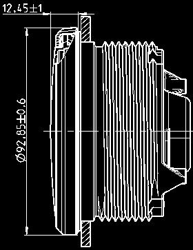
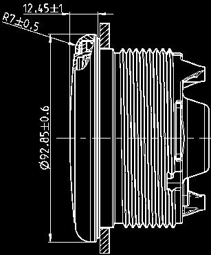

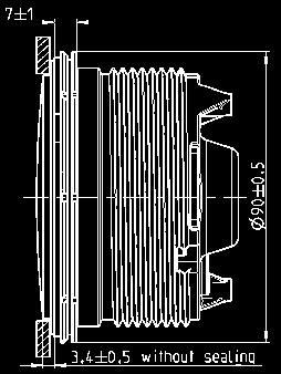
69 Gauges Fitting Details Gauges bezel types Ø 52 mm Gauges front fitting Ø 52 mm Gauges flush fitting Flat bezel Round bezel Triangle bezel No bezel (rear entry) Ø 52 mm Gauge and Clamp-Ring overall dimension Ø 52 mm Gauges & Brackets Ø 85 mm Gauges front fitting Ø 85 mm Gauges flush fitting Flat bezel Round bezel Triangle bezel No bezel (rear entry) Ø 85 mm Gauge and Clamp-Ring overall dimension Ø 85 mm Gauges & Brackets 69


70 Gauges Fitting Details Gauges bezel types Ø 110 mm Gauges front fitting Ø 110 mm Gauges flush fitting Flat bezel Round bezel Triangle bezel No bezel (rear entry) Ø 110 mm Gauge and Clamp-Ring overall dimension Ø 110 mm Gauges & Brackets 70
 Accuracy: +/- 2,5% of full scale reading Current consumption: <")
71 Sumlog & Tachourmeter Sumlog Technical Data Measurement Range: see Table Sensors: Sumlog SL/HS Sensor, Airmar Triducer NMEA 0183 LCD-Size: 37 x 11 mm Alarm output max: 100mA Illumination: amber, dimmable Installation depth: 50mm Installation diameter: 80 & 85mm Deflection angle: 240 Operating Voltage: 8,5 32 Volt (Sensor 8 16V) Accuracy: +/- 2,5% of full scale reading Current consumption: < 175 ma, including Warning LED Operating temperature: -20 C to +85 C; plated bezels (chrome) -20 C to +70 C Storage temperature: -40 C to +85 C for 48h; plated bezels (chrome) -40 C to +70 C +90 C for 1h Temperature shock Range: -40 C to +85 C; plated bezels (chrome) -40 C to +70 C Transformation time: 10 seconds Retention time: 2h Climatic test Range: +25 C to +55 C Relative. Humidity: 80% to 100% EMC: in conformity with ISO /2 ISO: ESD: in conformity with DIN_EN ISO/CD: SAE: J 551/15) Vibration Sinus: 2g; 8-500Hz; duration 16h Noise 4,2g; Hz, duration 8h Mechanical shock continuous 25g; 6ms; 1Hz Single shock 100g; 11ms Free fall 1m; 3 times Chemical resistance against - preservative agent - preservative agent remover - cold cleaner - methylated spirit - interior cleaner - drinks containing caffeine and tannin Nominal position NL 0 to NL 85 (DIN16257) Protection class according to IEC Front: IP67 (in Nominal position) Rear: IP52 (in Nominal position) Reverse polarity protection yes, 1 minute Short circuit protection yes, 1 minute Features High reliability Flush mount fitting LED Illumination Integrated Warning LED Design Housing PC; flame retarding (UL94) Bezel PC or ABS; several colours and shapes (see table) Lens PMMA; double lens Dial backlit; different colours (see table) Pointer backlit, white on black dials; red on white dials Illumination Dial: LED amber (605nm) Pointer: LED red (632nm) Warning LED red (632nm), programmable Mounting spin-lock Nut; locking height 0,5mm 20mm, optional Studs and Bracket; locking height 2 13mm Connection 8 pin MQS connector system Tachourmeter Technical Data Measurement Range: see Table Sensors: Terminal 1 (Ignition Coil, negative side) LCD-Size: 37 x 11 mm Alarm output max: 100mA Illumination: amber, dimmable Installation depth: 50mm Installation diameter: 80 & 85mm Deflection angle: 240 Operating Voltage: 8,5 32 Volt (Sensor 8 16V) Accuracy: +/- 2,5% of full scale reading Current consumption: < 175 ma, including Warning LED Operating temperature: -20 C to +85 C; plated bezels (chrome) -20 C to +70 C Storage temperature: -40 C to +85 C for 48h; plated bezels (chrome) -40 C to +70 C +90 C for 1h Temperature shock Range: -40 C to +85 C; plated bezels (chrome) -40 C to +70 C Relative. Humidity: 80% to 100% Protection class IP67 (front) in accordance to IEC Description Gauge to indicate Engine Revolution, Engine Hours, Voltage & Clock. Features Integrated Warning LED Changeable front bezel LED Illumination Flush mount possibility High Reliability Design Housing PC; flame retarding (UL94) Bezel PC or ABS; several colours and shapes (see table) Lens PMMA; double lens Dial backlit; different colours (see table) Pointer backlit, white on black dials; red on white dials Illumination Dial: LED amber (605nm) Pointer: LED red (632nm) Warning LED red (632nm), programmable Mounting spin-lock Nut; locking height 0,5mm 20mm, optional Studs and Bracket; locking height 2 13mm Connection 8 pin MQS connector system 71

72 Engine Synchroniser & Gauges (Differential Tacho) Technical Data Sensors: Hall sensor Inductive sensor Blocking oscillator Ignition Terminal 1 Alternator Terminal W amber, dimmable 50mm 80/85mm Illumination: Installation depth: Installation diameter: Deflection angle: +/- 120 Operating Voltage: 8,5 32 Volt Accuracy: +/- 2,5% of full scale reading Current consumption: < 175 ma, including Warning LED Operating temperature: -20 C to +85 C; plated bezels (chrome) -20 C to +70 C Storage temperature: -40 C to +85 C for 48h; plated bezels (chrome) -40 C to +70 C +90 C for 1h Temperature shock Range: -40 C to +85 C; plated bezels (chrome) -40 C to +70 C Transformation time: 10 seconds Retention time: 2h Climatic test Range: +25 C to +55 C Relative. Humidity: 80% to 100% EMC in conformity with ISO: /2 ISO ESD in conformity with DIN: EN ISO/CD SAE: J 551/15) Vibration Sinus: 2g; 8-500Hz; duration 16h Noise 4,2g; Hz, duration 8h Mechanical shock continuous 25g; 6ms; 1Hz Single shock 100g; 11ms Free fall 1m; 3 times Chemical resistance against - preservative agent - preservative agent remover - cold cleaner - methylated spirit - interior cleaner - drinks containing caffeine and tannin Nominal position NL 0 to NL 85 (DIN16257) Protection class according to IEC Front: IP67 (in Nominal position) Rear: IP52 (in Nominal position) Reverse polarity protection yes, 1 minute Features High reliability Flush mount fitting LED Illumination Integrated Warning LED Concept Housing PC; flame retarding (UL94) Bezel PC or ABS; several colours and shapes (see table) Lens PMMA; double lens Dial backlit; different colours (see table) Pointer backlit, white on black dials; red on white dials Illumination Dial: LED amber (605nm) Pointer: LED red (632nm) Warning LED red (632nm), programmable Mounting spin-lock Nut; locking height 0,5mm 20mm, optional Studs and Bracket; locking height 2 13mm Connection 8 pin MQS connector system Press. - Temp. - Fuel - Trim - Ammeter - Volt - Pyro Water Technical Specs 8 pole Tyco/Hirschmann MQS plug +/ 3.6 angle degree accuracy over the entire display area Operating voltage volt, volt with dropping resistor Current consumption < 130 ma with LED warning light Reverse polarity protection Input signal: standard Ohm values 90 display angle 52 mm installation diameter Anti-fog double lens Front panel in compliance with IP 67 protection rating Red LED warning light Optional makepoint 72

. The panel width may be within a range of 2 to 20 mm. For 52 mm instruments, the fastening nut can be mounted at position A or B.")


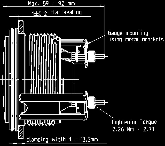
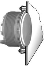
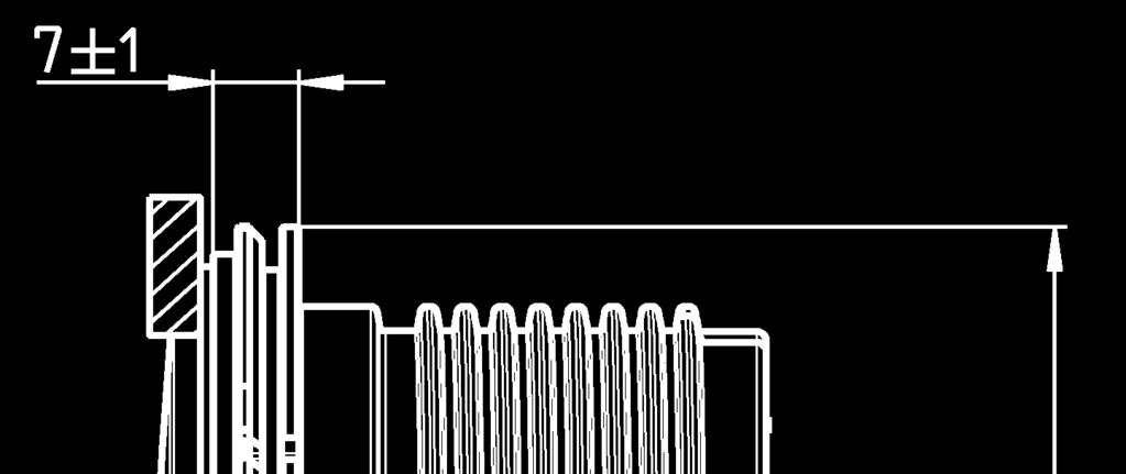
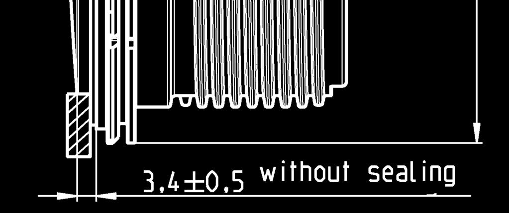
73 Gauge Fittings Fitting Ø 52 mm gauges To replace a bezel Place the new front ring on the instrument and press it on until it is flush with the instrument glass. Front ring, flat; black A2C Front ring, flat; white A2C Front ring, flat; chrome A2C Front ring, triangular; black A2C Front ring, triangular; white A2C Front ring, triangular; chrome A2C Front ring, round; black A2C Front ring, round; white A2C Front ring, round; chrome A2C To cut and fit gauge Ø52mm Conventional assembly. (Instrument is put into the drill hole from the front). The panel width may be within a range of 2 to 20 mm. For 52 mm instruments, the fastening nut can be mounted at position A or B. This allows you to fix the gauge in different panel bores. Version A Clamping height mm Version B Clamping height mm Align the instrument and hand-tighten the fastening nut. Ensure that the nut is not tightened with a torque greater than 400 Ncm. * Make sure the seal lays flat between the panel and the front ring. OR If you would like to omit the fastening nut, you may use the part set A2C as an alternative. This is recommended if the installation location is subject to vibratory loads. Screw the stud bolts into the provided drill holes in the enclosure. Max. stud bolt torque is 1.5 Nm. Place the bracket on the stud bolt and hand-tighten the knurled nut. To cut and fit gauge Ø52mm flush mount If the instrument is mounted flush (i. e., from the back so that the instrument glass and the panel form one plane), the front ring must be removed. Press the instrument glass with both thumbs, while at the same time pressing the front ring forward from the instrument with both index fingers. Note the use of a tool in the adjacent figure. Place the flush mount seal A2C on the instrument glass. Put the instrument into the drill hole from the back. Adjust the instrument so that the gauge is level and fasten it to the stud bolts on the rear side of the panel, using the flush mount fixing bracket A2C


. The panel width may be within a range of 2 to 20 mm.")


, the front ring must be removed.")
74 Gauge Fittings Fittings Ø 85mm gauges To replace a bezel Place the new front ring on the instrument and press it on until it is flush with the instrument glass. Front ring, flat; black A2C Front ring, flat; white A2C Front ring, flat; chrome A2C Front ring, triangular; black A2C Front ring, triangular; white A2C Front ring, triangular; chrome A2C Front ring, round; black A2C Front ring, round; white A2C To cut and fit gauge Ø85mm Conventional assembly. (Instrument is put into the drill hole from the front). The panel width may be within a range of 2 to 20 mm. For 85 mm instruments, the fastening nut can be mounted at position A or B. This allows you to fix the gauge in different panel bores. Version A Panel bore mm Circumferential lip away from instrument Version B Panel bore mm Circumferential lip next to instrument Align the instrument and hand-tighten the fastening nut. Ensure that the nut is not tightened with a torque greater than 400 Ncm. * Make sure the seal lays flat between the panel and the front ring. OR If you would like to omit the fastening nut, you may use the part set A2C as an alternative. This is recommended if the installation location is subject to vibratory loads. Screw the stud bolts into the provided drill holes in the enclosure. Max. stud bolt torque is 1.5 Nm. Place the bracket on the stud bolt and hand-tighten the knurled nut. To cut and fit gauge Ø85mm flush mount If the instrument is mounted flush (i. e., from the back so that the instrument glass and the panel form one plane), the front ring must be removed. Press the instrument glass with both thumbs, while at the same time pressing the front ring forward from the instrument with both index fingers. Note the use of a tool in the adjacent figure. Place the flush mount seal A2C on the instrument glass. Put the instrument into the drill hole from the back. Adjust the instrument so that the gauge is level and fasten it to the stud bolts on the rear side of the panel, using the flush mount fixing bracket A2C To unplug connector To remove the connector, press the latch (1) and pull the connector out (2). Note: Ø 110 Gauges require a panel bore of Ø 111 mm. Panel width may be within a range of 2 and 20 mm Flush mount seal is p/n A2C

 to change to the next value.")

")


75 Speedometer Sumlog Calibration Calibration for: Hall Effect Output Transducer For NMEA Transducer Change Input to NMEA. No pulse calibration needed. Press the key briefly (< 2sec.) to change the currently displayed value. Press the key longer (< 2sec.) to change to the next value. The display returns to normal operating mode (if a key is not pressed for 30 seconds. Any settings To enter calibration mode Press and hold Configuration Key Press the Config key to change over between the Frequency input (8 pole plug pin 5) and the NMEA0183 input (14 pole plug, pin 1 & 2) Press Configuration Key briefly Press and hold Configuration Key Set impulses number is displayed. The first digit flushes. Press Configuration Key briefly The flushing digit increases by 1. If the flushing digit is 9, the display returns to 0. Press Config key briefly The next lower digit flushes Press Config key briefly Deactivate Ignition power. This saves the impulse number in the display. Continue until the complete impulse number is set Press and hold Config key Deactivate Ignition power (T15). This saves the impulse number in the display. 75
 Press and hold Mode key (14-pin - Pin 12) Ignition Power On T.")

76 Speedometer Sumlog Alarm Threshold Setting of unit and Alarm Threshold Battery Power On T. 30 (8-pin - Pin1) Ignition Power Off T. 15 (8-pin - Pin4) Press and hold Mode key (14-pin - Pin 12) Ignition Power On T. 15 Release Mode key Press and hold Mode Key By briefly pressing the Mode key, you can switch between 24h and 12h (AM/PM) clock format. Press and hold Mode key Press the Mode key to change the water temperature unit from C to F. Press and hold Mode key Press Mode key briefly to change the water depth unit from von m to ft. Press and hold Mode key Press and hold Mode key Press and hold Mode key Set alarm threshold is displayed; the first digit flushes. Press Mode key briefly The flushing digit increases by 1. If the flushing digit is 9, the display returns to 0. Press and hold Mode key The next lower digit flushes in the display. Press Mode key briefly The flushing digit increases by 1. If the flushing digit is 9, the display returns to 0. Continue until the complete alarm threshold is set. Press and hold Mode key Switch Off Ignition power (T15). This saves the unit and the alarm threshold in the display. 76


77 Speedometer Sumlog Operation Display Selection Switch On Battery Power T. 30 (8-pin - Pin1) Switch On Ignition Power T. 15 (8-pin - Pin4) Odometer Tripmeter nm Press and hold Mode Key Depth nm Press and hold Mode key Time Press and hold Mode key Water temperature Press and hold Mode key Battery voltage Press and hold Mode key Resetting Trip Counter Switch On Battery Power T. 30 (8-pin - Pin1) Switch On Ignition Power T. 15 (8-pin - Pin4) Press the Mode key repeatedly until the trip distance are displayed. Press and hold Mode key Trip is now deleted 77
78 Speedometer Sumlog Clock & LCD Brightness Function Setting the Clock Battery Power On T. 30 (8-pin - Pin1) Ignition Power On T. 15 (8-pin - Pin4) Press the Mode key repeatedly until the time is displayed Press and hold Mode key Set time is displayed; the first digit flushes. Press Mode key briefly The flushing digit increases by 1. If the flushing digit is 9, the display returns to 0 Press and hold Mode key The next lower digit flushes. Press Mode key briefly The flushing digit increases by 1. If the flushing digit is 9, the display returns to 0. Continue until the correct time is set Press and hold Mode key Setting the Brightness Battery Power On T. 30 (8-pin - Pin1) Ignition Power On T. 15 (8-pin - Pin4) Press the Mode key repeatedly until the Voltmeter is displayed. Press Mode key briefly Press the Mode key repeatedly until the desired brightness is reached The brightness can be set between 0 (OFF) to 10 (max). Press and hold Mode key The desired brightness is now permanently set. 78
 Ignition Power Off T.")


79 Tachourmeter Tachourmeter Calibration Setting impulses / revolution Battery Power On T. 30 (8-pin - Pin1) Ignition Power Off T. 15 (8-pin - Pin4) Press and hold Configuration key (14-pin - Pin 12) To enter calibration mode Ignition Power On T. 15 Release Configuration key Press and hold Configuration Key Set impulse number is displayed, the first digit flushes. Press Configuration key briefly The flushing digit increases by 1. If the flushing digit is 9, the display returns to 0 Press and hold Configuration Key The next lower digit flushes Press Configuration Key briefly The flushing digit increases by 1. If the flushing digit is 9, the display returns to 0. Continue until the complete impulse number is set Press and hold Configuration Key Deactivate Ignition power T.15 This saves the impulse number in the display. 79
 Ignition Power Off T.")


80 Tachourmeter Tachourmeter Calibration Setting the unit and alarm threshold Battery Power On T. 30 (8-pin - Pin1) Ignition Power Off T. 15 (8-pin - Pin4) Press and hold Mode key (14-pin - Pin 12) Ignition Power On T. 15 Release Mode key Press and hold Mode key By briefly pressing the Mode key, you can switch between 24h and 12h (AM/PM) clock format. Press and hold Mode key Press Mode key briefly Press and hold Mode key Set alarm threshold is displayed; the first digit flushes. Press Mode key briefly The flushing digit increases by 1. If the flushing digit is 9, the display returns to 0 Press Mode key briefly Set alarm threshold is displayed; the first digit flushes. Press Mode key briefly The flushing digit increases by 1. If the flushing digit is 9, the display returns to 0 Press and hold Mode key Ignition Power Off T. 15. This saves the unit and the alarm threshold in the display. 80
 Total operating hours Press Mode key briefly Trip hours Press Mode key briefly Time Press Mode key briefly Vehicle voltage Press Mode key briefly Resetting the day counter Battery")
81 Tachourmeter Tachourmeter Calibration In operation Display indicator selection Battery Power On T. 30 (8-pin - Pin1) Ignition Power On T. 15 (8-pin - Pin4) Total operating hours Press Mode key briefly Trip hours Press Mode key briefly Time Press Mode key briefly Vehicle voltage Press Mode key briefly Resetting the day counter Battery Power On T. 30 (8-pin - Pin1) Ignition Power On T. 15 (8-pin - Pin4) Press the Mode key repeatedly until the trip hours are displayed. Press and hold Mode key Trip is now deleted. 81
 Ignition Power On T.")


 to 10")
82 Tachourmeter Tachourmeter Calibration Setting the Clock Battery Power On T. 30 (8-pin - Pin1) Ignition Power On T. 15 (8-pin - Pin4) Press the Mode key repeatedly until the time is displayed Press and hold Mode key Set time is displayed; the first digit flushes. Press Mode key briefly The flushing digit increases by 1. If the flushing digit is 9, the display returns to 0 Press and hold Mode key The next lower digit flushes. Press Mode key briefly The flushing digit increases by 1. If the flushing digit is 9, the display returns to 0. Continue until the correct time is set Press and hold Mode key Setting the Brightness Battery Power On T. 30 (8-pin - Pin1) Ignition Power On T. 15 (8-pin - Pin4) Press the Mode key repeatedly until the Voltmeter is displayed. Press Mode key briefly Press the Mode key repeatedly until the desired brightness is reached The brightness can be set between 0 (OFF) to 10 (max). Press and hold Mode key The desired brightness is now permanently set. 82
Table of contents. Viewline
 Table of contents Table of contents Viewline Introducing VDO Viewline 01 Sumlog 05 Depth / Triducer / Pitot-Tube Speedometer 06 Wind 07 Tachometer 08 Synchronizer 09 Speed and Revolution Sensors 09 Rudder
Marine Catalogue 2014/2015
 Marine Catalogue 2014/2015 www.vdo.at Table of contents / Introducing VDO Viewline Table of contents Viewline Introducing VDO Viewline 01 GPS Speedometer / Sumlog 04 Depth / Triducer / Pitot-Tube Speedometer
Table of contents. Viewline
 Table of contents Table of contents Viewline Introducing VDO Viewline 01 Sumlog 05 Depth / Triducer / Pitot-Tube Speedometer 06 Wind 07 Tachometer 08 Synchronizer 09 Speed and Revolution Sensors 09 Rudder
2011 Special OEM Instrumentation Catalog
 www.vdo.com/usa 2011 Special OEM Instrumentation Catalog Part #VSOC0510 (Supersedes Part #VSOC0908) Instrumentation Sensors A heritage of engineering quality and innovation We re focused on providing our
INSTRUMENTATION & ENGINE MONITORING SYSTEMS
 INSTRUMENTATION & ENGINE MONITORING SYSTEMS 2018 2019 INDEX How to use the Catalogue 2 COCKPIT INTERNATIONAL Overview 3 Parts Listing 4 Installations instructions 26 VIEWLINE ALL-WEATHER ACCESSORIES Overview
Catalogue
 Catalogue 2015 www.vdo.net.au We re focused on providing our customers with the best possible instrumentation a goal that we ve pursued since 1920. We continue to work to deliver the functionality, durability,
Catalogue
 Catalogue 2016 www.vdo.net.au We re focused on providing our customers with the best possible instrumentation a goal that we ve pursued since 1920. We continue to work to deliver the functionality, durability,
Cockpit White. Cockpit Vision. Cockpit Digital. Cockpit International. CANcockpit. Performance Gauges. Cockpit Titanium. Kimax
 CONTENTS Cockpit Vision 4-14 Cockpit International 15-25 Cockpit Titanium 26-32 Cockpit White 33-38 Cockpit Digital 39-40 CanCockpit Gauges 41-43 Performance Gauges 44 Kimax 45-46 Alarm & Central Locking
Special OEM Solutions Catalog Sensors
 www.vdo-instruments.com Special OEM Solutions Catalog Instruments Senders Sensors Accessories Camera Systems VDO engineering: quality, reliability and innovation We re focused on providing our customers
Timeless Instruments MARINE INSTRUMENTS. Premium Marine Instruments. AcquaLink. OceanLink. 1 Marine Instruments AMI Marine Catalogue
 Premium Marine Instruments Timeless Instruments With over 50 years of experience, VDO stands as one of the oldest marine suppliers in the industry. This sustained level of success is the product of our
A comprehensive family of instruments for outboards, stern drives and inboards, including diesels!
 Introduction Premier features black dials with mondern white and blue graphics. When lighted, white dial grads become red and pointer lights white. These instruments feature automotive type light- piping
Timeless Instruments MARINE INSTRUMENTS. Premium Marine Instruments. AcquaLink. OceanLink. 1 Marine Instruments AMI Marine Catalogue
 Premium Marine Instruments Timeless Instruments With over 50 years of experience, VDO stands as one of the oldest marine suppliers in the industry. This sustained level of success is the product of our
Vehicle Electronics Catalog
 Update 2014 Vehicle Electronics Catalog www.vdo.com - www.it.vdo.com Special OEM Solutions for Automotive, Industry and Marine The Future of Mobility Starts with Today s Innovations As a global supplier
CAN Instruments CANcockpit* Ocean Link Accessories. * Only for trained partners
 CAN Instruments * Only for trained partners 1.3.1 CANcockpit* 1.3.2 Ocean Link 1.3.3 Accessories CANcockpit* Handle complex requirements with ease. The VDO brand is synonymous with customised solutions
Article VDO black N N N N N
 4 Made in Germany black white VDO black VDO white Description Ø Scale Volt 4.000 4.000B N02 420 7 N02 420 702 Amperometer 80-0 - 80 4.000 4.000B N02 400 3 N02 400 306 Amperometer with shunt 80-0 - 80 4.00013
VDO Marine Instruments
 VDO Marine Instruments VDO North America is a worldwide supplier of electronic information and control systems. Since 1921, we have been a leader in instrument and sensor technology, providing leading-edge
SUZUKI INSTRUMENTS. 4 Speedometer. 4 Tachometer. 2 Fuel Gauge
 SUZUKI INSTRUMENTS Economically priced, high quality instruments feature easy plug-in wiring connections, perimeterlighted dial, polished stainless steel bezels, contoured pointers and fog resistant glass
Elite stainless steel bezels White graphics and black background on spun aluminum dials
 Introduction With its rich luster and polish, Black Sterling instruments convey a look of the utmost sophistication and add elegance to any dash. These instruments have fireorange pointer tips and spun
InstrumentatIon & engine monitoring systems
 InstrumentatIon & 2012 engine monitoring systems INDEX Content Page How to use the Catalogue 2-3 Cockpit International Overview 5 Parts Listing 6-22 Technical Information 23 Installation instructions
OceanLink easy to install VDO CAN instrumentation for sports boats.
 OceanLink easy to install VDO CAN instrumentation for sports boats www.vdo.com Plug & Play the fastest way to access precision engine data Engines on modern sports and leisure boats increasingly feature
VDO Marine Timeless instruments.
 www.vdo-marine.com VDO Marine Timeless instruments. Timeless instruments. VDO supplies marine solutions for pleasure boats, yachts and sailing boats since 1958, wherewith with 60 years of experience VDO
Product Information. Viewline Temperature gauges. Description. Gauge to indicate Coolant-, Engine oil-, Air- and Exhaust temperature.
 Product Information www.vdo.com Viewline Temperature gauges Description Gauge to indicate Coolant-, Engine oil-, Air- and Exhaust temperature. Features _ Integrated Warning LED. _ Changeable Frontbezels.
A comprehensive family of instruments for outboards, stern drives and inboards, including diesels!
 Introduction Hottest selling black dial line! Amega has cleanlooking black dials with white and red graphics plus throughdial and perimeter lighting for great readability. Amega has been very popular,
AcquaLink Maximum reliability and progressive technology in premium quality.
 www.marine.vdo.com AcquaLink Maximum reliability and progressive technology in premium quality. 2 AcquaLink Content Content System architecture 6 Instrumentation 8 TFT displays 8 Wind gauges 9 Compass
SECTION INDEX. Whether the need is for a simple voltmeter or a complex monitoring system, look to Blue Sea Systems for a solution.
 88 Metering Solution-Oriented Metering Keeping track of onboard systems is critical to safety and peace of mind. Running low on fuel or not knowing about a failing battery can lead to dangerous situations.
GAUGES. Honda NMEA NMEA 2000 Speedometer. NMEA 2000 Gauge Kit NMEA Gauge Kit
 Honda NMEA 2000 The Honda NMEA 2000 tachometer and speedometer gauges display engine and vessel data received from up to five engines on the same NMEA 2000 backbone or bus. These gauges feature analog
New Products Programs & Packaging
 #3 Catalog New Products Programs & Packaging from NEW Performance Products Custom instruments engineered to give you the reliability and accuracy you need on the street, off road or track. The choice of
High-impact moisture-resistant polyester (PBT)
") INSTRUMENTS Rugged products for demanding O.E.M. applications DESCRIPTION: Full line of heavy-duty gauges, tachometers & speedometers ideally suited for rugged O.E.M. off-highway, industrial & specialty
INSTRUMENTS Rugged products for demanding O.E.M. applications DESCRIPTION: Full line of heavy-duty gauges, tachometers & speedometers ideally suited for rugged O.E.M. off-highway, industrial & specialty
IS0306 rev. B ecn /2013. MG Tachometer (NMEA2000 and J-1939) TACH 1760 RPM FUEL. Installation / User Manual.
 TACH 1760 RPM FUEL. Installation / User Manual.") IS0306 rev. B ecn 9055 11/2013 MG3000 - Tachometer (NMEA2000 and J-1939) TACH 1760 RPM FUEL Installation / User Manual www.faria-instruments.com IMPORTANT: This User s Guide outlines the functionality
IS0306 rev. B ecn 9055 11/2013 MG3000 - Tachometer (NMEA2000 and J-1939) TACH 1760 RPM FUEL Installation / User Manual www.faria-instruments.com IMPORTANT: This User s Guide outlines the functionality
6 Gauge Box Set with Programmable Speedometer. Made in the USA. Caution. Speedometer Parts. Tachometer Parts. Fuel Level Gauge Parts.
 6 Gauge Box Set with Programmable Speedometer Caution Disconnect the battery during installation. Tighten nuts on the backclamp only slightly more than you can tighten with your fingers. Six inch-pounds
Speedo With Telltales and Display 85mm Tech Support Instruction Sheet # A2C Rev
 Gauge Installation: 1. Select the desired mounting location of the instrument. 2. Depending on your mounting situation it might be necessary to configure the gauge before installation. See page 2 - Setting
Full Sweep Minor Gauge Wiring:
 Full Sweep Minor Gauge Wiring: Notes on Senders: Temp Hi match/vdo 150C: Normally used in Oil temp, 140 280F. Temp Low match/vdo120c: Normally used in water temp, 100 240F. To test the gauges work (oil,
Classic style with a name you can trust
 Classic style with a name you can trust Bosch is known for precision, engineering, and innovation. Add style and you have the first-ever line of Bosch gauges, including replacement tachometers, speedometers,
DISPLAYS: Revolution counters and Speedometers
 DISPLAYS: Revolution counters Revolution counters MOTOMETER revolution counters are equipped with a moving coil measuring unit that shows the exact engine speed. The use of revolution counters is either
S E T L R E U C M T E R N O T N A I T C
 I N S T E R L U E MC E T NR T O AN T I I C O S N & INSTRUMENTATION RANGE Fuel Gauge Hourmeter 10,000 hrs Oil Pressure Gauge (SW) 0-80 PSI Oil Pressure Gauge (SW) 0-100 PSI Water Pressure Kit (Outboard)
Rugged Reliable Innovative Instruments for Automotive Commercial Industrial Performance Recreational Marine Military
 Aftermarket Catalog - 2019 We Have Moved - 75 North Frontage Road, Suite 106, North Stonington, CT 06359 Rugged Reliable Innovative Faria Beede Instruments, Inc. has been manufacturing gauges and instruments
Time Access & Automotive Systems
 Time Access & Automotive Systems Tel : 011 326 4146-082 375 3280 www.timeandautomotive.co.za Time Access & Automotive Systems TAS Product Range: Biometrics / Time & Attendance / Access Control Facial Recognition
Viewline Instrument Kit Installation Instructions. Rev E. Important Installation Notes:
 Read these instructions thoroughly before installation. Do not deviate from assembly or wiring diagram. Always disconnect battery ground before making any electrical connections. IMPORTANT: Mounting dimensions
Dress White Standard Gauge
 187 Energy The Panther battery energy gauges allow you to determine the exact amount of charge remaining in your batteries. They are perfect for any boating, automotive, or industrial use, and can be used
Owner s Manual. MG2000 Speedometer IS0211. for use with SmartCraft Tachometer
 Owner s Manual MG2000 Speedometer for use with SmartCraft Tachometer IS0211 rev. E ecr#6395 08/2006 4/5/05 Changes 12/21 Index Description Available Functions for display page 1 Default Screens page 1
Camaro Camaro
 Important facts about this kit. 1. The dash panel used in this picture is used by permission of Covan's Classic. We Make Wiring Easy! 2. This kit requires some modification to your original under dash
Dress White Standard Gauge
 172 Energy The Panther battery energy gauges allow you to determine the exact amount of charge remaining in your batteries. They are perfect for any boating, automotive, or industrial use, and can be used
6 Gauge Box Set IS0333
 Caution 6 Gauge Box Set IS0 Rev. B ecr 882 9/202 Disconnect the battery during installation. Tighten nuts on the back clamp only slightly more than you can tighten with your fingers. Six inch-pounds of
DASHBOARDS LM Instrumentation Dashboards Maxima Clusters...7 ENGINE MONITORING AND CONTROL MODULE...8. MULTI-FUNCTION DISPLAY CANbus...
 Contents DASHBOARDS Dashboards...2-6 Maxima Clusters...7 ENGINE MONITORING AND CONTROL MODULE...8 MULTI-FUNCTION DISPLAY CANbus...9-11 CANbus INSTRUMENTS...12-13 HOURMETERS...14-17 VOLTAGE, CURRENT, TEMPERATURE,
Switch select of sender types:
 Full sweep minor gauges wiring: B -------------------------------------------------- battery or +12V input. L -------------------------------------------------- LED illumination, for back lighting, dimmable.
Suzuki Instruments. Suzuki Genuine Instruments are. custom-designed to provide the. quality, reliability and value you. expect from Suzuki Products.
 Suzuki Instruments Suzuki Genuine Instruments are custom-designed to provide the quality, reliability and value you expect from Suzuki Products. The wide selection allows you to accurately monitor a variety
5 Gauge Box Set IS0342
 Caution 5 Gauge Box Set IS0342 Rev. B ecr 8832 9/202 Disconnect the battery during installation. Tighten nuts on the back clamp only slightly more than you can tighten with your fingers. Six inch-pounds
MARINE GAUGE PRODUCTS
 2 R1(12x) 130 (3x) 130 R39.5 42 2 2011 MARINE GAUGE PRODUCTS +0.1 0 7. 5 38.1 5.5 9.5 1.1 R0.6 2.4 R3 4.5 7.1 24.8 R60 1.50 16.2 B D R23 R26 1. 5(3x) B 4.5 1.5 48.5 A 24 24 30 39.1 ø42 SmartCraft Technology
SUZUKI MODULAR INSTRUMENT SYSTEM
 SUZUKI MODULAR INSTRUMENT SYSTEM (SMIS) uses an easy to connect and expandable cable system to transmit graphic and numerical data to Multi-Function gauges. Easy to set up and install system can be used
2 diameter gauges (nominal), panel cut-out /-.02 ; 3-3/8 diameter tachometer/speedometer (nominal), panel cut-out /-.
, panel cut-out /-.02 ; 3-3/8 diameter tachometer/speedometer (nominal), panel cut-out /-.") INSTRUMENTS Specially designed products for O.E.M. automotive styling DESCRIPTION: Full line of purpose-built gauges, tachometers & speedometers are ideally suited for O.E.M. applications requiring high-performance
INSTRUMENTS Specially designed products for O.E.M. automotive styling DESCRIPTION: Full line of purpose-built gauges, tachometers & speedometers are ideally suited for O.E.M. applications requiring high-performance
4 speedometer Easy to read 4 Speedometer features include lighted dial, contoured pointer and fog resistant glass lens. *Requires Tubing
 instruments 99105-80000 4 tachometer / without monitor 99105-80002 99105-80001 4 tachometer / monitor 4 tachometer 7,000 max R.P.M. Tachs are available with or without 4-Stroke monitor functions. Monitor
Marine Instruments Catalogue
 Marine Instruments Catalogue 2007/2008 _ Navigation _ Engine Monitoring _ Sensors _ Accessories _ Technical Data www.siemensvdo.com 1. Navigation 1.1 Chart Plotters 4 1.2 Ocean Line Navigation, black
Dress White Standard Gauge
 169 Energy The Panther battery energy gauges allow you to determine the exact amount of charge remaining in your batteries. They are perfect for any boating, automotive, or industrial use, and can be used
EVINRUDE ICON GAUGES.
 EVINRUDE ICON 2 FROM THE MAKERS OF THE ULTIMATE OUTBOARD EVINRUDE ICON GAUGES. THE ULTIMATE GAUGES ARE HERE. FROM THE NO-NONSENSE BASIC SERIES TO THE FUNCTION- FILLED PRO SERIES, EVINRUDE ICON OFFERS BOATERS
EVINRUDE ICON GAUGES.
 EVINRUDE ICON 2 FROM THE MAKERS OF THE ULTIMATE OUTBOARD EVINRUDE ICON GAUGES. The ultimate gauges are here. FROM The no-nonsense BASIC SERIES TO ThE FUNCTIONfilled Pro Series, Evinrude ICON offers boaters
AURORA SERIES GAUGES FUEL GAUGE SUGGESTED TOOLS AND MATERIALS. 3 3 /8 in (85.7 mm) PARTS LIST
 PARTS LIST") GAUGE INSTALLATION. Select mounting locations for the fuel gauge. 2. Cut a 2 /6 (52 mm) diameter hole for the gauge and test for proper fitmate. 3. Tighten the gauge with the enclosed Aurora Mounting Clamp
GAUGE INSTALLATION. Select mounting locations for the fuel gauge. 2. Cut a 2 /6 (52 mm) diameter hole for the gauge and test for proper fitmate. 3. Tighten the gauge with the enclosed Aurora Mounting Clamp
OMEGA KUSTOM INSTRUMENTS
 4O5O 6O 7O 8O 9O 1OO MPH 3O 1OO 2O Gauge Installation Manual 1O O OMEGA KUSTOM INSTRUMENTS 14O 12O 13O Operations Omega Kustom Gauges Speedometer: The speedometer can be set up to display MPH or KPH. There
6 Gauge Box Set IS0332
 Caution 6 Gauge Box Set IS0 Rev. A ecr 878 /0 Disconnect the battery during installation. Tighten nuts on the back clamp only slightly more than you can tighten with your fingers. Six inch-pounds of torque
(oem version) AT A GLANCE FEATURES. Instruments available for most outboards, stern drives and gasoline-powered inboards
 AT A GLANCE FEATURES. Instruments available for most outboards, stern drives and gasoline-powered inboards") ISSUE DATE AUG09 DATA SHEET NO USAOEMG2 AT A GLANCE FEATURES Instruments available for most outboards, stern drives and gasolinepowered inboards Scratchresistant domed glass lenses Enhanched illumination:
ISSUE DATE AUG09 DATA SHEET NO USAOEMG2 AT A GLANCE FEATURES Instruments available for most outboards, stern drives and gasolinepowered inboards Scratchresistant domed glass lenses Enhanched illumination:
Montage- und Bedienungsanleitung Installation and Operating Instructions
 Montage- und Bedienungsanleitung Installation and Operating Instructions Wind VDO Kienzle Vertrieb und Service GmbH Installation and Operating Instructions Page 22-40 21 22 Table of contents CONTENTS Preface..........................................
SPA MICROPROCESSOR COMBINED TACHO&SPEEDO/GAUGE INSTALLATION AND OPERATING MANUAL PAGE 2...INSTRUMENT FEATURES PAGE 3...OPERATING INSTRUCTIONS
 SPA MICROPROCESSOR COMBINED TACHO&SPEEDO/GAUGE INSTALLATION AND OPERATING MANUAL PAGE 2...INSTRUMENT FEATURES PAGE 3...OPERATING INSTRUCTIONS PAGE 3...MENU SYSTEM PAGE 9...INSTALLATION DIAGRAMS PAGE 13...INSTALLATION
ELECTRICAL PANELS. Chap.
 ELECTRICAL PANELS 360 Panel System Electrical Panels 360 Panel System Modular Panels DC Electric Panels AC Electric Panels AC/DC Electric Panels Aber Marine Panels IP 67 Watertight Panels Rotary Switch
AcquaLink Nav Box and System AcquaLink Installation Instruction 06/ EN (3.0)
") AcquaLink www.marine.vdo.com Nav Box and System AcquaLink Installation Instruction 06/2016 - EN (3.0) AcquaLink Content Content 1. Preliminary Remarks 4 2. Safety Instructions 5 2.1 Installation 5 2.2
AcquaLink www.marine.vdo.com Nav Box and System AcquaLink Installation Instruction 06/2016 - EN (3.0) AcquaLink Content Content 1. Preliminary Remarks 4 2. Safety Instructions 5 2.1 Installation 5 2.2
2007 Mercury Marine SmartCraft Gauges
 i 27 Mercury Marine SmartCraft Gauges 9-89828315 97 ii TABLE OF CONTENTS System Tachometer/Speedometer Basic Operation and Features...1 Automatic Engine Detection Feature...1 Master Reset...2 Alarm Warnings...3
Automotive Commercial Commercial Marine Industrial Marine Military Performance Recreational
 fm-002-0001 rev. H 8/2013 1 With some of the most sophisticated information and instrumentation systems in the industry, and a range of products that are rugged enough to survive on military Humvee and
Model 10 Electromechanical Totalizer
 Model 10 Electromechanical Totalizer A 6 figure general purpose, rugged, electromechanical counter, either panel or base mounted, with manual knob reset, key reset, or non-reset. Frame and housing provides
THIS MANUAL DESCRIBES THE SMARTCRAFT GAUGE SYSTEMS AVAILABLE FOR YOUR BOAT
 Systems Monitor Operation Manual THIS MANUAL DESCRIBES THE SMARTCRAFT GAUGE SYSTEMS AVAILABLE FOR YOUR BOAT 2004, Mercury Marine 90-895202 204 0 TABLE OF CONTENTS Legend..............................................
INSTRUMENTATION & CONTROL
 Irrigation Controller.................... 172 Window Controller.................... 174 Water Meter Controller.................. 176 Digital Level Switch.................... 177 Filtration Controller Set..................
PLATINUM SERIES SWITCHBOARD METERS
 PLATINUM SERIES SWITCHBOARD METERS www.sifamtinsley.co.uk DATASHEET E471457 Multifunction Meters Transducers & Isolators PLATINUM SERIES SWITCHBOARD METERS Temperature Controllers Converters & Recorders
EMS-2. Introduction. Features. Engine Management System. Operating Manual English 1.07
 EMS-2 Engine Management System Operating Manual English 1.07 Introduction The EMS-2 is a multifunction engine information display and early warning engine monitoring system. It has been specifically designed
Digital Fuel Gauge P/n (With Dual Ohms Range option)
") Digital Fuel Gauge P/n 301.530 (With Dual Ohms Range option) Green Brown Red 12V 90 Ohms 180 Ohms Ignition Gauge Rear View Green 180R (Sw S_180) Brown 90R (Sw S_90) 180 Ohms 90 Ohms Front Fuel tank unit
Digital Fuel Gauge P/n 301.530 (With Dual Ohms Range option) Green Brown Red 12V 90 Ohms 180 Ohms Ignition Gauge Rear View Green 180R (Sw S_180) Brown 90R (Sw S_90) 180 Ohms 90 Ohms Front Fuel tank unit
CUSTOMER WIRING INSTRUCTIONS TO SUIT: BA-BF XR6 and XR8 Universal Auto or Manual Trans
 , CUSTOMER WIRING INSTRUCTIONS TO SUIT: BA-BF XR6 and XR8 Universal Auto or Manual Trans Lay the C.A.E Engine loom in vehicle and plug in all the sensors. ( The sensor plugs can only be connected one way
FP-100 Fuel Pressure and Ammeter Indicator Page 1 of 16. All specification subject to change Aerospace Logic Inc.
 Page 1 of 16 All specification subject to change 2002-2003 FP-100 Operations and Installation Manual This manual is certified for use with instrument serial number ASL000000 Use of this manual with any
PHLOX II. Ignition Control Systems. On-board diagnostics. Complete ignition system. Up to 16 cylinders. Precise ignition timing
 PHLOX II Ignition Control Systems Ignition Control Coil Rails Ignition Leads Pickups Coils Complete ignition system Precise ignition timing Increased spark plug durability Easy integration via CAN On-board
EGT-100 Operations and Installation Manual
 Page 1 of 11 All specification subject to change 2002-2005 EGT-100 Operations and Installation Manual This manual is certified for use with instrument serial number ASL000000 Use of this manual with any
PRESSURE TRANSDUCERS. Specifications. Individual Specifications
 GEMS COMPLIANT 00 Series and 00 Heavy Duty Series Compact OEM Pressure Transmitters 0 00 psi to 0-0,000 psi ranges (0- bar to 0-,00 bar) High Proof Pressures Broad Choice of Outputs RoHS Compliant For
INSTALLATION GUIDE Ford Mustang Digital Dash Panel Part Number: DP7009 Year Series:
 Made in America Lifetime Guarantee Thank you for purchasing this gauge panel from Intellitronix. We value our customers! INSTALLATION GUIDE Ford Mustang Digital Dash Panel Part Number: DP7009 Year Series:
2016 GENUINE RIGGING-PARTS AND ACCESSORIES
 2016 GENUINE RIGGING-PARTS AND ACCESSORIES Dear Customer, Quality. Dependability. Innovation. Everything that you expect from your outboard motors is delivered with style by SUZUKI. Demand no less from
2
 Handling a complex world Installation and Operating Instructions Tachometer CAN Master Easy Link Gauge Installation and Operating Instructions 2 Contents Tachometer CAN Master Preliminary Remarks 4 Safety
SPEK PRO MONITOR AND CONTROL
 Programming Instructions for : Temperature 2 1/16 Spek Pro Racing Gauge - NASCAR ECU Compatible SPEK PRO MONITOR AND CONTROL Refer to the Flow Chart Programming Instructions while reviewing this guide.
Commander IS0128 ISO128E ECR# /04. Tachometer/ Engine Hourmeter
 Commander Tachometer/ Engine Hourmeter Analog Tachometer Digitally displays Hours Engine Has Been Run Fuel Level Other Features if Available: Fuel anagement Fuel Flow in GPH or LPH Total or Trip Fuel Used
Sea Water Temperature Gauge
 SST-110 I Sea Water Temperature Gauge Table of Contents Introduction............................ 3 Installation..............................5 Operation...............................7 Key Functions...........................
INSTRUMENT PANEL AND GAUGES INSTRUMENT PANEL AND GAUGES XJ
 J INSTRUMENT PANEL AND GAUGES 8E - 1 INSTRUMENT PANEL AND GAUGES GROUP INDEX INSTRUMENT PANEL AND GAUGES XJ... 1 INSTRUMENT PANEL AND GAUGES YJ... 24 INSTRUMENT PANEL AND GAUGES XJ CONTENTS page DIAGNOSIS...
Classic Instruments & 1956 Chevy. Installation Manual
 Classic Instruments 1955 & 1956 Chevy Installation Manual Table of Contents Welcome from the Team at Classic Instruments!... 3 Disassemble Original Gauge... 4 Assemble New Gauge Cluster... 5 Speedo, Tach,
Removing and installing dash panel insert
 Removing and installing dash panel insert Caution To disconnect and connect the battery, the procedure described in the workshop manual should be strictly adhered to Chapter. Note Pull off multi-pin connector
Oil Pressure Display Gauges Part numbers: Analog Oil/Fuel SAE Pressure Gauge psi Analog Oil SAE Pressure Gauge.
 Oil Pressure Display Gauges Part numbers: 30-5133 - Analog Oil/Fuel SAE Pressure Gauge. 0-100psi 30-5135 - Analog Oil SAE Pressure Gauge. 0-150psi AEM's Analog style Oil Pressure Gauges feature quick response
INSTALLATION GUIDE Chevrolet Impala/Caprice Digital Dash Panel Part Number: DP1208 Year Series: 1968
 Made in America Lifetime Guarantee Thank you for purchasing this instrument from Intellitronix. We value our customers! INSTALLATION GUIDE Chevrolet Impala/Caprice Digital Dash Panel Part Number: DP1208
INSTALLATION GUIDE Six Gauge Universal Digital Dash Panel Part Number: DP10002
 Made in America Lifetime Guarantee Thank you for purchasing this digital dash panel from Intellitronix. We value our customers! INSTALLATION GUIDE Six Gauge Universal Digital Dash Panel Part Number: DP10002
CONTROLLERS & SPECIAL VALVES
 CONTROLLERS & SPECIAL VALVES G75-C 1, 2 & 4 Valve Controllers.... 70 G75-C-1W & 1W+ Window Controller... 72 G75-DP Differential Pressure Switch.....................................................................
INSTALLATION GUIDE Chevrolet Digital Dash Panel Part Number: DP6003 Year Series:
 INSTALLATION GUIDE Chevrolet Digital Dash Panel Part Number: DP6003 Year Series: 1967-1972 * Disconnect the battery before attempting any electrical work on your vehicle. * KIT COMPONENTS One (1) Digital
NEW VINTAGE INSTRUMENT AND GAUGE KIT INSTALLATION INSTRUCTIONS
 NEW VINTAGE INSTRUMENT AND GAUGE KIT INSTALLATION INSTRUCTIONS REV.01-033113 INDEX THE BASICS CLUSTER INSTALLATION TACHOMETER OPERATION SPEEDOMETER OPERATION TROUBLESHOOTING WIRING DIAGRAM pg.2 pg. 2 pg.
Electromagnetic flowmeters Series FLOMAT Insertion electromagnetic flowmeter for conductive liquids
 Electromagnetic flowmeters Series FLOMAT Insertion electromagnetic flowmeter for conductive liquids For use in large diameter pipes as an economical solution for flow measurement Flow rate measurement
XC Instrumentation System Owner s Manual Revision /05/06
 XC Instrumentation System Owner s Manual Revision 3.0 07/05/06 XC INSTRUMENTATION SYSTEM OWNER S MANUAL 1 Revision History Date New Revision Level Revision Description 11/08/05 1.0 Initial release 05/24/06
ODYR-25-1 & SLX-25-1 rev. A VACUUM/BOOST PRESSURE, TEMP, and EGT GAUGE
 ODYR-25-1 & SLX-25-1 rev. A VACUUM/BOOST PRESSURE, TEMP, and EGT GAUGE SENSOR CONNECTION: The vac./boost sensor has 1/8 NPT on the end which can be treaded into the intake track, or into a pipe adapter
INSTALLATION GUIDE Chevrolet Monte Carlo Dash Panel Part Number: DP9002 Year Series:
 Made in America Lifetime Guarantee Thank you for purchasing this instrument from Intellitronix. We value our customers! INSTALLATION GUIDE Chevrolet Monte Carlo Dash Panel Part Number: DP9002 Year Series:
PRESSURE TRANSDUCERS. Specifications. Individual Specifications
 00 Series and 00 Heavy Duty Series Compact OEM Pressure Transmitters 0 50 psi to 0-0,000 psi ranges (0-.5 bar to 0-,00 bar) High Proof Pressures Broad Choice of Outputs RoHS Compliant For OEMs that need
Section K Contents. Pyrometers... K 425 Thermocouples... K 428 Pyro-Switches... K 430. Trim Tabs... K 431
 K HI Section K Contents Faria Styles & Descriptions... K 403 Multi-function Gauges... K 406 MG Series... K 407 Depth Sounder... K 409 Fuel Manager... K 410 Antares... K 411 Boxed Sets & L.E.D Lighting...
Mustang. Installation Manual. Revision 11/16/10
 1967-1968 Mustang Installation Manual Revision 11/16/10 I Table of Contents TABLE OF CONTENTS...II WELCOME TO THE TEAM OF CLASSIC INSTRUMENTS!... III REMOVE ORIGINAL INSTRUMENT PANEL...1 DETERMINE SPEEDOMETER
ANSI Switchboard Meters
 ANSI Switchboard Meters High quality range of switchboard instruments with Class 1 accuracy and which complies with American ANSI-C39.1 (1981) specifications. Available in 4 1 /2" case size, the rugged
GENUINE SUZUKI ACCESSORIES
 GENUINE SUZUKI ACCESSORIES MARINE 2009 NOW HEAR THIS! Dear Customer, Quality. Dependability. Innovation. Everything you expect from your outboard motor is delivered with style by Suzuki. Demand no less