TECHNICAL MANUAL. Henny Penny High Volume Open Fryer. Model OFE/OFG-341 Model OFE/OFG-342 Model OEA/OGA-341 Model OEA/OGA-342
|
|
|
- Laureen Wheeler
- 6 years ago
- Views:
Transcription
1 Henny Penny High Volume Open Fryer Model OFE/OFG-341 Model OFE/OFG-342 Model OEA/OGA-341 Model OEA/OGA-342 TECHNICAL MANUAL
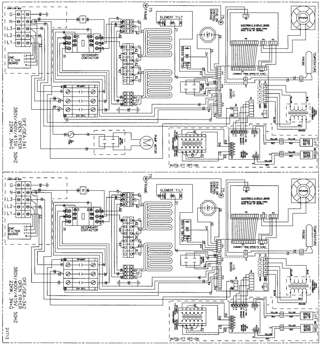
2 This manual should be retained in a convenient location for future reference. A wiring diagram for this appliance is located on the inside of the right side panel. Post in a prominent location, instructions to be followed in event user smells gas. This information shall be obtained by consulting the local gas supplier. Do not obstruct the flow of combustion and ventilation air. Adequate clearance must be left all around appliance for sufficient air to the combustion chamber. The Model OFG/OGA-34X open fryer is equipped with a continuous pilot. But the open fryer can not be operated without electric power. The unit will automatically return to normal operation when power is restored. To avoid a fire, keep appliance area free and clear from combustibles. Improper installation, adjustment, alteration, service or maintenance can cause property damage, injury or death. Read the installation, operating and maintenance instructions thoroughly before installing or servicing this equipment. FOR YOUR SAFETY, DO NOT STORE OR USE GASOLINE OR OTHER FLAMMABLE VAPORS AND LIQUIDS IN THE VICINITY OF THIS OR ANY OTHER APPLIANCE. FM Revised
3 TABLE OF CONTENTS Section Page Section 1. TROUBLESHOOTING Introduction Safety Troubleshooting Error Codes Section 2. MAINTENANCE Introduction Maintenance Hints High Temperature Limit Control (Gas Units) Complete Control Panel Replacement Power Switch Temperature Probe Replacement (Gas) Temperature Probe Replacement (Electric) Flame Sensor/Pilot/Ignitor Assembly (Gas) Ignition Module Transformer Replacement Control & I/O Boards Replacement Vacuum Switch Replacement Drain Microswitch Replacement Filter Switch Replacement Gas Control Valve Replacement Blower Motor Replacement Heating Elements (Electric) Heating Contactors (Electric) Speaker Assembly High Temperature Limit Control (Electric) Filter Pump and Motor Removal Autolift Transformer Replacement (if applicable) Autolift PC Board Replacement (if applicable) Autolift Actuator (Motor) Replacement (if applicable) Wiring Diagrams Section 3. PARTS INFORMATION Introduction Genuine Parts When Ordering Parts Prices Delivery Warranty Recommended Spare Parts for Distributors ii 106


4 SECTION 1. TROUBLESHOOTING 1-1. INTRODUCTION This section provides troubleshooting information in the form of an easy to read table. If a problem occurs during the first operation of a new fryer, recheck the Installation Section of the Operator s Manual. Before troubleshooting, always recheck the Operation Section of the Operator s Manual SAFETY Where information is of particular importance or is safety related, the words DANGER, WARNING, CAUTION, or NOTE are used. Their usage is described on the next page: SAFETY ALERT SYMBOL is used with DANGER, WARNING or CAUTION which indicates a personal injury type hazard. NOTICE is used to highlight especially important information. CAUTION used without the safety alert symbol indicates a potentially hazardous situation which, if not avoided, may result in property damage. CAUTION used with the safety alert symbol indicates a potentially hazardous situation which, if not avoided, could result in minor or moderate injury. WARNING indicates a potentially hazardous situation which, if not avoided, could result in death or serious injury. DANGER INDICATES AN IMMINENTLY HAZARDOUS SITUATION WHICH, IF NOT AVOIDED, WILL RESULT IN DEATH OR SERIOUS INJURY. Oct
5 1-3. TROUBLESHOOTING To isolate a malfunction, proceed as follows: 1. Clearly define the problem or symptom and when it occurs. 2. Locate the problem in the Troubleshooting table. 3. Review all possible causes, then one at a time work through the list of corrections until the problem is solved. If maintenance procedures are not followed correctly, injuries and/or property damage could result. PROBLEM CAUSE CORRECTION With the switch in the ON position, fryer is completely inoperative Open circuit Check to see if unit is plugged in Check breaker or fuse at supply box Check power switch per Power Switch Section; replace if defective Check voltage at wall receptacle Check cord and plug Shortening will not heat but lights are on Faulty contactor (elec. Model) Faulty gas control valve (gas model) Faulty temperature probe Faulty high limit Faulty drain switch Check contactor per Heating Contactors Section Check gas control valve per Gas Control Valve Assembly Section Check temperature probe per Temperature Probe Replacement Section; E6 Check high limit per the appropriate High Temperature Limti Control Section; E10 Check drain switch per Drain Microswitch Section; E Dec. 2016
6 1-3. TROUBLESHOOTING (Continued) PROBLEM CAUSE CORRECTION Heating of shortening too slow Low or improper voltage (elec. unit) Use a meter and check the receptacle voltage against the data plate Shortening overheating Foaming or boiling over of shortening Weak or burnt out elements (elec. unit) Wire(s) loose Burnt or charred wire connection Faulty contactor Supply line too small low gas volume (gas unit) Improper ventilation Temperature probe needs calibrated Mercury contactor stuck closed bad control board Water in shortening Improper or bad shortening Improper filtering Improper rinsing after cleaning the fryer Check heating elements per Heating Elements Section Tighten Replace wire and clean connectors Check contactor per Heating Contactors Section Increase supply line size; refer to Installation Section of Operator s Manual Refer to Installation Section of Operator s Manual Calibrate temperature probe if 10 off; if more than 10 off, replace temperature probe Check mercury contactor for not opening; replace if necessary (elec. unit) Replace control board if heat indicator stays on past ready temperature At end of cook cycle, drain shortening and clean Use recommended shortening Refer to the Filtering the Shortening Section in Operator s Manual Clean and rinse the frypot; then dry thoroughly
7 Dec TROUBLESHOOTING (Continued) PROBLEM CAUSE CORRECTION Shortening will not drain from Drain valve clogged with crumbs Open valve, force cleaning brush frypot through drain Filter motor runs but pumps shortening slowly Filter switch on, motor does not run Drain valve will not open by turning handle Pump clogged Filter line connection loose Solidified shortening in lines Defective switch Defective motor Motor thermal protector tripped Replace cotter pins in valve coupling Remove pump cover and clean Tighten all filter line connections Clear all filter lines of solidified shortening Check/replace switch per Filter Switch Section Check/replace motor Reset thermal switch on filter motor Motor hums but will not pump Clogged lines or pump Remove and clean pump lines Replace pump seal, rotor and roller
8 1-4 Dec ERROR CODES In the event of a control system failure, the digital display shows An error message. These messages are coded: E4, E5, E6, E10, E15, E20, E31, E41, E46, and E92. A Constant tone is heard when an error code is displayed, and to silence this tone, press any button. DISPLAY CAUSE PANEL BOARD CORRECTION E-4 Control board overheating Turn switch to OFF position, then turn switch back to ON; if display shows E4, the control board is getting too hot; check the louvers on each side of the unit for obstruction E-5 E-6A E-6B E-10 E-15 E-31 E-41 E-46 Shortening overheating Temperature probe open Temperature probe shorted High limit Drain switch failure Elements not hinged all the way down Programming failure Turn switch to OFF position, then turn switch back to ON; if display shows E5, the heating circuits and temperature probe should be checked Turn switch to OFF position, the turn switch back to ON; if display shows E6, the temperature probe should be checked Turn switch to OFF position, the turn switch back to ON; if display shows E6, the temperature probe should be checked to replace, per Temperature Probe Replacement Section Reset the high limit by manually pushing up on the red reset button; if high limit does not reset, high limit must be replaced per High Limit Temperature Control Section Close drain, using the drain valve handle; if display still shows E-15, check the drain microswitch per Drain Microswitch Section Check to make sure the elements are hinged all way down into the frypot; check for obstructions under elements way down Turn switch to OFF, then back to ON; if display shows any of the error codes, try to reinitialize the control (Special Program Mode Section of Operator s Manual); if error code persists, replace the control panel per Complete Control Panel Replacement Section
9 Dec ERROR CODES (Continued) DISPLAY CAUSE PANEL BOARD CORRECTION Press the timer button to try the ignition E-20 A Vacuum switch failure (stuck closed) process again, and if E-20 A persist, check the air switch per Vacuum Switch Section E-20 B E-20 C E-20 D E-47 E-48 E-70 E-92 Draft fan or vacuum switch failure (stuck open) Ignition modules not responding Pilots not lit or no flame sense Analog converter chip or 12 volt supply failure Input system error Faulty power switch or switch wiring; faulty I/O board 24 VAC fuse on I/O open Press the timer button to try the ignition process again and if E-20 B persist, check the vacuum switch per Vacuum Switch Section or the blower motor per Blower Motor Assembly Section Press the timer button to try the ignition process again; if E-20 C persists, check the ignition module per Ignitor Module Section, the spark ignitor per Pilot/Ignitor Module Section, the I/O board per Control & I/O Boards Section Presst eh timer button to try the ignition process again; if E-20 D persists, check the igniton module per Ignition Module Section, the I/O board per Control & I/O Boards Section or the flame sense per Flame Sensor Section Turn the switch to OFF, then turn back to ON; if E-47) persists, replace the I/O board, or the PC board; if speaker tones are quiet, probably I/O board failure Replace PC board Check power switch, along with its wiring; replace I/O board if necessary Check for shorted component in 24 volt circuit; (i.e., high limit, drain switch, vacuum switch)

10 1-6 Dec SECTION 2. MAINTENANCE 2-1. INTRODUCTION This section provides procedures for the check out and replacement of the various parts used within the fryer. Before replacing any parts refer to the Troubleshooting Section. It will aid you in determining the cause of the malfunction MAINTENANCE HINTS 1. You may need to use a multimeter to check the electric components. 2. When the manual refers to the circuit being closed, the multimeter should read zero unless otherwise noted. 3. When the manual refers to the circuit being open, the multimeter will read infinity HIGH TEMPERATURE LIMIT CONTROL (Gas Units) This high temperature control is a safety, manual reset control, which senses the temperature of the shortening. If the shortening temperature exceeds 425 F (218 C), this switch opens and shuts off heat to the frypot. When the temperature of the shortening drops to a safe operation limit, the control must be manually reset by pressing the red reset button. The red reset button is located under the control panel, in the front of the fryer. (Figure 2-1). This allows heat to be supplied to the frypot. Checkout Figure 2-1 Before replacing a high temperature limit control, check to see that its circuit is closed. The shortening temperature must be below 380 F (193 C) to accurately perform this check. To avoid electrical shock or property damage, move the power switch to OFF and disconnect main circuit breaker, or unplug cord at wall receptacle. 1. Remove the control panel. Figure 2-2.


11 Figure 2-2 Oct HIGH TEMPERATURE 2. Using a Phillip s head screwdriver, remove the screws securing LIMIT CONTROL the inner heat shield and remove from unit. Figure 2-3. (Gas Units) (Continued) Figure Remove the screw securing the high limit bracket to the frame and remove the high limit and bracket from unit. Figure 2-4. Figure Remove the two screws securing the high limit to the bracket and remove the high limit from bracket. 5. Remove the two electrical wires from the high temperature limit control. Figure 2-5. Figure Manually reset the control, then check for continuity between the two terminals after resetting the control. If the circuit is open, replace the control, then continue with this procedure. (If the circuit is closed, the high limit is not defective. Reconnect the two electrical wires.)
 (Continued) Replacement To avoid electrical shock or property damage, move the power switch to OFF and disconnect main circuit breaker, or unplug cord at")


12 2-2 Oct HIGH TEMPERATURE LIMIT CONTROL (Gas Units) (Continued) Replacement To avoid electrical shock or property damage, move the power switch to OFF and disconnect main circuit breaker, or unplug cord at wall receptacle. 1. If the tube is broken or cracked, the control opens, shutting off electrical power to the heat circuit. The control cannot be reset, and it continuously clicks when pushed. 2. Drain the shortening from the frypot and discard. A substance from the tube could contaminate the shortening. Figure Remove the control panel. 4. Using a 5/16 wrench, loosen small inside screw nut on capillary tube. Figure Using a 11/16 crows-foot, remove the larger nut securing the capillary tube to the pot. Figure Remove the two screws securing the high limit guard and Figure 2-7 remove guard. Figure 2-8 Figure Straighten the capillary tube inside the frypot, and pull the capillary tube through the frypot, from behind the control panel. Remove the defective high limit from the control panel area. 8. Replace new high limit in reverse order. To avoid electrical shock or other injury, run the capillary line under and away from all electrical power wires and terminals. The tube must never be in such a position where it could accidentally touch the electrical power terminals.

 from control panel. They must be installed on the replacement panels. 5. Install new control panel in reverse order.")
13 Oct COMPLETE CONTROL Should the control board become inoperative, follow these PANEL REPLACEMENT instructions for replacing the board. 1. Remove electrical power supplied to the unit. To avoid electrical shock or property damage, move the power switch to OFF and disconnect main circuit breaker, or unplug cord at wall receptacle. 2. Remove the two screws securing the control panel and lift out. Figure 2-9 Figure Unplug the wire connectors going to the control panel. Figure Remove transformer(s) from control panel. They must be installed on the replacement panels. 5. Install new control panel in reverse order. Figure 2-10 When plugging connectors onto new control panel, be sure the connectors are inserted onto all of the pins, and that the connectors are not forced onto the pins backwards. If not connected properly, damage to the board could result POWER SWITCH 1. Remove electrical power supplied to fryer. To avoid electrical shock or property damage, move the power switch to OFF and disconnect main circuit breaker, or unplug cord at wall receptacle. 2. Remove control panel. Figure Label and remove wires from the switch. With test instrument check across the terminals of the switch with switch in the on position, and the circuit should be closed. In the off position, the circuit should be open. If the switch checks defective,

 to the control board. If it becomes disabled, E06 shows in the display.")

14 replace by continuing with this procedure. Figure May POWER SWITCH (Continued) 4. With control panel removed, and the wires off the switch, push in on tabs on the switch to remove from panel. Figure Replace with new switch, and reconnect wires to switch. 6. Replace the control panel. Figure TEMPERATURE PROBE The temperature probe relays the actual shortening temperature REPLACEMENT (Gas) to the control board. If it becomes disabled, E06 shows in the display. Also, if the shortening temperature is out of calibration more than 10 F or C, the probe should be replaced. An Ohm check can be performed also. See chart below. 1. Remove electrical power supplied to the fryer. Figure 2-13 To avoid electrical shock or property damage, move the power switch to OFF and disconnect main circuit breaker, or unplug cord at wall receptacle. 2. Drain the shortening from the frypot. 3. Remove the control panel and heat shield from control area. Figure Using a ½ inch wrench, remove the nut on the compression
 6. Place the nut and new ferrule on the new probe and insert the probe into the compression fitting until it extends one (1) inch (2.54cm) into the frypot. Figure 2-16. 7.")
 to the control board.")
15 Figure 2-14 fitting. Figure Aug TEMPERATURE PROBE 5. Remove the probe from the frypot, and disconnect wire REPLACEMENT (GAS) connector from the control panel. Figure (Continued) 6. Place the nut and new ferrule on the new probe and insert the probe into the compression fitting until it extends one (1) inch (2.54cm) into the frypot. Figure Tighten hand tight and then a half turn with wrench. Figure 2-15 Excess force will damage probe. 8. Connect new probe to PC board and replace control panel. Figure Replace shortening, and turn power on to check out fryer TEMPERATURE PROBE The temperature probe relays the actual shortening temperature REPLACEMENT (Gas) to the control board. If it becomes disabled, E06 shows in the REPLACEMENT display. Also, if the shortening temperature is out of calibration (ELECTRIC) more than 10 F or C, the probe should be replaced. An Ohm check can also be performed. See chart on page Remove electrical power supplied to the fryer. To avoid electrical shock or property damage, move the power switch to OFF and disconnect main circuit breaker, or unplug cord at wall receptacle. 2. Drain the shortening from the frypot.
 (Continued) 5. Remove the probe from the frypot, and disconnect probe. 6.")
16 Figure Remove screws securing rear cover of fryer, and remove rear cover. Figure Dec TEMPERATURE PROBE 4. Using a ½ inch wrench, remove the nut on the compression REPLACEMENT fitting. Figure (ELECTRIC) (Continued) 5. Remove the probe from the frypot, and disconnect probe. 6. Place the nut and new ferrule on the new probe and insert the probe into the compression fitting until it extends one (1) inch (2.54cm) into the frypot. Figure Reconnect new probe onto wires, replace rear cover, and fryer is now ready for use FLAME SENSOR/ The Henny Penny open fryer (gas) has electronic spark ignition PILOT / IGNITOR that lights a standing pilot. The gap between the spark electrode ASSEMBLY (GAS) and the pilot hood should be1/8 of an inch (3.18 mm). The flame sensor recognizes the pilot flame and allows gas to continue to the pilot. The flame sensor must send a minimum of two (2) micro amps to the ignition module. The pilot flame should be split in two by the flame sensor, causing the flame sensor to be bright red in color. 1. Remove electrical power supplied to the unit. To avoid electrical shock or property damage, move the power switch to OFF and disconnect main circuit breaker, or unplug cord at wall receptacle. TO AVOID PERSONAL INJURY OR PROPERTY DAMAGE, BEFORE STARTING THIS PROCEDURE, MOVE THE MAIN POWER SWITCH TO THE OFF POSITION. DISCONNECT THE MAIN CIRCUIT BREAKERS AT THE CIRCUIT BREAKER BOX OR UNPLUG SERVICE CORD FROM WALL RECEPTACLE. TURN OFF THE MAIN GAS SUPPLY TO THE FRYER AND DISCONNECT AND CAP THE MAIN SUPPLY LINE TO FRYER, OR
 (Continued) 2.")


17 POSSIBLE EXPLOSION COULD RESULT. Oct FLAME SENSOR/ PILOT / IGNITOR ASSEMBLY (Gas) (Continued) 2. Remove the control panel and heat shield from control area. Figure Figure Disconnect the flame sense wire from ignition module. Figure Figure Using a 7/16 wrench, loosen the nut on the pilot tube and pull tube from assembly. Figure Figure Remove the two screws securing the assembly and pull assembly from unit. Figure Figure Now the flame sensor or or pilot assembly can be removed from bracket.


18 2-8 Oct IGNITION MODULE During normal operation, the ignition modules send 24 volts to the ignitors and gas valve. If a module does not sense a pilot flame, the module starts the ignition process again. But, if a pilot light goes out for longer that 10 seconds, or it goes out 3 times within 10 seconds, the module keeps the 24 volts from reaching the gas valve. The burners shut down. 1. Remove electrical power supplied to the unit. To avoid electrical shock or property damage, move the power switch to OFF and disconnect main circuit breaker, or unplug cord at wall receptacle. Figure Remove the control panel and heat shield from control area. Figure Using a 3/8 inch socket, remove the two nuts securing the module. Figure Figure Label and remove the wires at module. Figure Install new module in reverse order. Figure 2-25


19 Oct TRANSFORMER The transformer reduces voltage down (to 24V) to accommodate REPLACEMENT those components with low voltage. 1. Remove electrical power supplied to the unit. To avoid electrical shock or property damage, move the power switch to OFF and disconnect main circuit breaker, or unplug cord at wall receptacle. Figure Remove the control panel 3. Remove the two wire connectors to disconnect transformer From panel. Figure Using a 3/8 nut-driver, remove the two nuts securing the transformer to the panel and remove transformer. Figure Figure Install the new transformer in reverse order CONTROL & I/O 1. Remove electrical power supplied to the unit. BOARDS REPLACEMENT I/O Power Supply Figure 2-28 Control To avoid electrical shock or property damage, move the power switch to OFF and disconnect main circuit breaker, or unplug cord at wall receptacle. 2. Remove the control. 3. Using a 5/16 nut-driver or wrench, remove the 4 nuts securing the PC shield and remove shield. Figure Disconnect the wire assemblies from the appropriate board. 5. Using a 5/16 nut-driver or wrench, remove the 4 nuts securing the appropriate board to the shroud. 6. Install the new board in reverse order Oct. 2003


20 2-12. VACUUM SWITCH This switch senses the airflow from the induction blower. If REPLACEMENT the airflow is reduced below a set amount, the switch opens and the I/O board cuts power to the gas control valve, which shuts the pilot flame off. 1. Remove electrical power supplied to the unit. Figure 2-29 To avoid electrical shock or property damage, move the power switch to OFF and disconnect main circuit breaker, or unplug cord at wall receptacle. 2. Remove the control panel. 3. Remove the 2 screws securing the switch to the heat shield. Figure Remove the air hose from the air switch. Figure Figure Label and remove wires from air switch. Figure Install new vacuum switch in reverse order. Figure 2-31 To avoid property damage, do not tamper with, or disas semble this component. It is set and sealed from the factory and is not to be adjusted. Oct


21 2-13. DRAIN MICROSWITCH Upon turning the drain handle, the drain microswitch should REPLACEMENT open, cutting off the pilot flame. This will prevent the fryer from heating while shortening is being drained from the frypot. 1. Remove electrical power supplied to the unit. To avoid electrical shock or property damage, move the power switch to OFF and disconnect main circuit breaker, or unplug cord at wall receptacle. 2. The following check should be made to determine if the drain microswitch is defective. Figure 2-32 a. Remove the two screws and nuts securing the microswitch to the drain rod valve bracket, and remove microswitch. Figure b. Remove wires from the switch. Figure c. Check for continuity across the two outside terminals of the drain switch. If the circuit is open, the drain switch is defective. The circuit opens by pressing on the actuator of the microswitch. Figure FILTER SWITCH REPLACEMENT 3. If defective, replace switch in reverse order. 1. Remove electrical power supplied to the unit. To avoid electrical shock or property damage, move the power switch to OFF and disconnect main circuit breaker, or unplug cord at wall receptacle. 2. Open the door (left door on 2 well units), and remove the 2 Figure 2-34 screws securing the switch box cover. Figure Oct. 2003
 switch in the on position, the circuit should be closed. With the switch in the off position, the circuit should be open.")
22 2-14. FILTER SWITCH 3. Label and remove the wires from the switch. With test REPLACEMENT instrument check across the terminals of the switch. With the (Continued) switch in the on position, the circuit should be closed. With the switch in the off position, the circuit should be open. If the switch is defective, replace by continuing with this procedure. Figure Figure With wires removed from the switch, push in on tabs on the switch and remove switch from front of switch box cover. Figure Push new switch into panel and reconnect wires. Figure GAS CONTROL VALVE The gas valve assembly controls the flow of gas to the pilot and the REPLACEMENT main burner. The valve has two 24-volt coils, which are regulated by the P and M terminals on the valve. The C terminal is the common terminal. For gas flow to the pilot, 24 VAC must be present between the P and C terminals. For gas flow to the main burner, 24 VAC must be present between the M and C terminals. TO AVOID PERSONAL INJURY OR PROPERTY DAMAGE, BEFORE STARTING THIS PROCEDURE, MOVE THE MAIN POWER SWITCH TO THE OFF POSITION. DISCONNECT THE MAIN CIRCUIT BREAKERS AT THE CIRCUIT BREAKER BOX OR UNPLUG SERVICE CORD FROM WALL RECEPTACLE. TURN OFF THE MAIN GAS SUPPLY TO THE FRYER AND DISCONNECT AND CAP THE MAIN SUPPLY LINE TO FRYER, OR POSSIBLE EXPLOSION COULD RESULT. Oct


23 2-15. GAS CONTROL VALVE REPLACEMENT (Continued) 1. Remove right side panel. Figure Figure Label and remove wires from gas valve. Figure 2-38 Figure Using a 7/16 wrench, remove the pilot line from the gas valve. Figure Figure Using a 1-inch wrench, loosen the nut securing the main gas inlet line to the gas valve. Figure Figure Oct. 2003


24 2-15. GAS CONTROL VALVE REPLACEMENT (Continued) 5. Using a pipe wrench, loosen the outlet fitting to the burner. Figure Figure Using a Phillips screwdriver, remove the 2 screws securing the gas valve to the bracket and remove gas valve from unit. Figure Figure Remove the fittings from the gas valve and install in new gas valve. 8. Install the new gas valve in reverse order BLOWER MOTOR The blower motor assembly induces the draft for the burners. If the REPLACEMENT blower motor fails, the air switch will fail to close, causing an E-20B error code in the display. 1. Remove electrical power supplied to the unit. To avoid electrical shock or property damage, move the power switch to OFF and disconnect main circuit breaker, or unplug cord at wall receptacle. 2. Remove screws securing the rear cover to the unit. Figure 2-43 Figure Jan


25 2-16. BLOWER MOTOR REPLACEMENT (Continued) 3. Remove the wire cover from the blower motor housing. Figure Figure Remove wire nuts connecting blower motor wires to wires in conduit. Figure Figure Loosen conduit from blower motor. Figure Figure Remove screws connecting flue to blower. Figure Figure Oct. 2003
 Heating elements are available for 208 and 230 voltage. Check data plate to determine correct voltage.")

26 2-16. BLOWER MOTOR REPLACEMENT (Continued) 8. Using 3/8 inch nut driver, remove nuts securing blower to the unit. Figure Pull blower from unit. Figure Install new blower in reverse order HEATING ELEMENTS (ELECTRIC) Heating elements are available for 208 and 230 voltage. Check data plate to determine correct voltage. Checkout If the shortening temperature recovery is very slow or at a slower rate than required, this may indicate defective heating element(s). An ohmmeter quickly indicates if the elements are shorted or open. 1. Remove electrical power supplied to the frypot to be checked Figure 2-49 To avoid electrical shock or property damage, move the power switch to OFF and disconnect main circuit breaker, or unplug cord at wall receptacle, to the frypot to be worked on. Be aware the other control on 2-frypot units will have power. 2. Remove rear cover. Figure Using a flat-head screwdriver, remove the appropriate wires from the terminal blocks. Figure Figure 2-50 Jan

27 2-17. HEATING ELEMENTS 4. Perform an ohm check on one element at a time, with wires (ELECTRIC) disconnected. The 2 elements actually have 3 small heating (Continued) elements inside the outer plate. It s important to check between the correct wires to obtain an accurate ohm reading. The wires are labeled for your convenience. If the resistance is not within tolerance, replace the element. Wire Nos. Voltage Wattage Ohms (cold) 1L1 to 1L L2 to 1L L3 to 1L L1 to 1L L2 to 1L L3 to 1L Replacement 1. Drain the shortening from the frypot 2. Remove the high limit bulb holder from the heating element inside the frypot. See High Limit Temperature Control-Electric Section. 3. Using a Phillip s-head screwdriver, remove the screws securing the element to the element hinges. Figure Pull element from fryer and replace with new element, following steps in reverse order. Figure Connect the power cord to the wall receptacle or close wall circuit breaker. Heating elements should never be energized without shortening in the frypot, or damage to the elements could result. 6. Replace the shortening in the frypot, and unit is ready for operation Oct. 2003
28 2-18. HEATING Each well of an electric fryer requires two switching contactors. CONTACTORS The first in line is the primary contactor and the second in line is (ELECTRIC) the heat contactor. When open, the primary contactor does not allow power to flow to the heat contactor. When closed, the primary supplies voltage to the heat contactor. When the heat contactor is open, no voltage is supplied to the heating elements. When the heat contactor closes, voltage is supplied to the heating elements. Checkout (Power Removed) 1. Remove electrical power supplied to frypot to be worked on. Heat Contactor (Mercury) To avoid electrical shock or property damage, move the power switch to OFF and disconnect main circuit breaker, or unplug cord at wall receptacle, to the frypot to be worked on. Be aware the other control on 2-frypot units will have power. 2. Remove the control panel. 3. Perform a check on the contactor as follows: 33 Test Points Results From 23 to 29 open circuit 37 From 24 to 28 open circuit From 25 to 27 open circuit From 30 to 34 open circuit From 31 to 35 open circuit From 32 to 36 open circuit From 33 to 37 ohm reading 1700 Figure 2-52 From 22 to 26 ohm reading 415 Wires should be removed and labeled to obtain an accurate check of contactors. Figure 2-53 Oct

29 2-18. HEATING CONTACTORS (ELECTRIC) (Continued) To avoid electrical shock, make connections before applying power, take reading, and remove power before removing meter leads. The following checks are performed with the wall circuit breaker closed and the main power switch in the ON position. 1. Re-apply power to unit and turn power switch to ON. 2. Using illustrations from previous page, check voltage as follows: Test Points Heat Contactor From terminal 34 to 35 From terminal 35 to 36 From terminal 34 to 36 Test Points Primary Contactor From terminal 27 to 28 From terminal 28 to 29 From terminal 27 to 29 Results The voltage should read the same at each terminal It should correspond to the voltage stated on the data plate. Replacement (Heat Contactor) If neither contactor is defective it must be replaced as follows: To avoid electrical shock or property damage, move the power switch to OFF and disconnect main circuit breaker, or unplug cord at wall receptacle, to the frypot to be worked on. Be aware the other control on 2-frypot units will have power. 1. Remove only the wires directly connected to the contactor Figure 2-54 being replaced. Label the wires for replacement. Figure Oct. 2003


30 2-18. HEATING CONTACTORS (ELECTRIC) Continued) 2. Remove the screws securing the contactor to the shroud, and remove contactor. Figure Install new contactor, and see steps 4 and 5. Figure 2-55 Replacement (Primary Contactor) 1. Remove only the wires directly connected to the contactor being replaced. Label the wires for replacement. Figure Remove screws securing contactor to unit and remove contactor. Figure Figure Install new contactor. 4. Reinstall the control panel. Figure Reconnect power to the fryer and test for proper operation. Oct


31 2-19. SPEAKER ASSEMBLY The speaker assembly emits audible signals to let the operator know when cooking and hold times are finished. 1. Remove electrical power supplied to unit. Figure 2-58 To avoid electrical shock or property damage, move the power switch to OFF and disconnect main circuit breaker, or unplug cord at wall receptacle. 2. Remove control panel. 3. Pull the power switch connector from back of panel. Figure Figure Pull the transformer connectors from back of panel. Figure Figure Using a 5/16 nutdriver or wrench, remove the 4 nuts securing the PC board shield and pull shield from studs. Figure Pull the speaker connector from control board. Figure Figure Using a 5/16 nut-driver or wrench, remove the 2 nuts securing the speaker to the shield and remove speaker from panel. Figure Install new speaker in reverse order. Figure Oct. 2003
 ening temperature exceeds 425 F (218 C), this switch opens and shuts off heat to the frypot, and E10 shows in control display.")

32 2-20. HIGH TEMPERATURE This high temperature control is a safety, manual reset control, LIMIT CONTROL which senses the temperature of the shortening. If the short- (ELECTRIC) ening temperature exceeds 425 F (218 C), this switch opens and shuts off heat to the frypot, and E10 shows in control display. When the temperature of the shortening drops to a safe operation reset the high limit by pressing the reset button. The reset button is located behind the frypot, in the element hinge. A small instrument, such as a Phillip s head screwdriver, or Allen wrench must be used to reset the high limit. This allows heat to be supplied to the frypot once again. See Figure Figure 2-63 Before replacing a high temperature limit control, check to see that its circuit is closed. The shortening temperature must be below 380 F (193 C) to accurately perform this check. 1. Remove electrical power supplied to fryer. Checkout To avoid electrical shock or property damage, move the power switch to OFF and disconnect main circuit breaker, or unplug cord at wall receptacle. 2. Remove rear cover of fryer. Figure Figure Remove the two screws securing the high limit to the bracket and pull high limit from bracket. Figure Figure 2-65 Jan


 Replacement To avoid electrical shock or property damage, move the power switch to OFF and disconnect main circuit breaker, or unplug cord at wall")
33 2-20. HIGH TEMPERATURE LIMIT CONTROL (ELECTRIC) (Continued) 4. Pull back cardboard cover and remove the two electrical wires from the high temperature limit control. Figure Figure Manually reset the control, then check for continuity between the two terminals after resetting the control. If the circuit is open, replace the control, then continue with this procedure. (If the circuit is closed, the high limit is not defective. Reconnect the two electrical wires.) Replacement To avoid electrical shock or property damage, move the power switch to OFF and disconnect main circuit breaker, or unplug cord at wall receptacle, to the frypot to be worked on. Be aware the other control on 2-frypot units will have power. 1. Drain the shortening from the frypot. Figure Remove capillary from brackets on upper part of element. Figure Remove capillary bulb from bulb holder inside the frypot. Figure Oct. 2003

34 2-20. HIGH TEMPERATURE LIMIT CONTROL (ELECTRIC) (Continued) 4. Straighten the capillary tube, and pull capillary tube through the hole in the element hinge, from the rear of the fryer. 5. Remove the defective control from the fryer. Figure Straighten the capillary tube on the new high limit, and thread the capillary tube through the hole in the element hinge. Figure Reattach the capillary to the brackets on the upper and lower parts of the elements. DO NOT crimp or kink the capillary tube during installation. Also, keep capillary tube behind element to protect from damage from the basket or during cleaning. Damage to the capillary tube reduces the life of the high limit, or causes the high limit to fail. 8. Connect wires to new high limit body and fasten to bracket, using the two screws removed in the checkout part of this section. Make sure red reset button of high limit lines up with the plunger that inserts into the element hinge. To avoid electrical shock or other injury, run the capillary line under and away from all electrical power wires and terminals. The tube must never be in such a position where it could accidentally touch the electrical power terminals 9. Re-install the rear cover and unit is now ready for use. Oct

, and remove the 2 screws securing the switch box cover and pull filter motor")

35 2-21. FILTER PUMP AND 1. Remove electrical power supplied to unit. MOTOR REMOVAL To avoid electrical shock or property damage, move the power switch to OFF and disconnect main circuit breaker, or unplug cord at wall receptacle. 2. Open the door (left door on 2 well units), and remove the 2 screws securing the switch box cover and pull filter motor wires from filter switch. Figure Figure Remove the 2 screws securing the switch box to the frame. Figure 2-71 Figure Loosen screws on conduit connector and pull conduit from the connector. Figure Figure Disconnect filter union to filter in drain pan. 6. Using a pipe wrench, disconnect the outlet pipe to frypot. Figure Figure Oct. 2003

 To avoid electrical shock or property damage, move the power switch to OFF and disconnect")

36 2-21. FILTER PUMP AND 7. Remove left side panel. MOTOR REMOVAL (Continued) 8. Using 9/16 socket or wrenches, remove the bolts and nuts securing the motor to the bracket and pull pump, motor, and piping from unit. Figure Figure AUTOLIFT 1. Remove electrical power supplied to unit. TRANSFORMER REPLACEMENT (if applicable) To avoid electrical shock or property damage, move the power switch to OFF and disconnect main circuit breaker, or unplug cord at wall receptacle. 2. Remove control panel. 3. Label and remove wires from transformer. Figure Figure Using 3/8 nut-driver or wrench, remove nuts securing transformer to panel and remove transformer from panel. Figure Figure Install new transformer in reverse order. Oct
 Autolift PC Board To avoid electrical shock or property damage, move the power switch to OFF and disconnect main circuit breaker, or unplug cord at wall receptacle. 2.")

37 2-23. AUTOLIFT PC BOARD 1. Remove electrical power supplied to unit. REPLACEMENT (if applicable) Autolift PC Board To avoid electrical shock or property damage, move the power switch to OFF and disconnect main circuit breaker, or unplug cord at wall receptacle. 2. Remove control panel 3. Disconnect connectors from PC board. Figure Using 5/16 nut-driver or wrench, remove the 4 nuts securing the autolift PC board to the panel and remove PC board from panel. 5. Install new panel in reverse order AUTOLIFT 1. Remove electrical power supplied to unit. ACTUATOR (MOTOR) REPLACEMENT (if applicable) To avoid electrical shock or property damage, move the power switch to OFF and disconnect main circuit breaker, or unplug cord at wall receptacle. 2. Drain shortening from frypot. Figure Remove basket and knock pin from basket hanger. Figure Remove rear cover. Figure Figure Jan. 2006
 5.")


38 2-24. AUTOLIFT ACTUATOR (MOTOR) REPLACEMENT (if applicable) 5. Disconnect actuator connector. Figure Figure Remove female connector from plate. Figure Figure 2-81 Figure Using 7/16 socket, remove the 4 nuts securing the support plate. 2 nuts are behind the insulation. Figures 2-82 & Figure 2-83 Oct


39 2-24. AUTOLIFT ACTUATOR (MOTOR) REPLACEMENT (if applicable) 8. Remove the 2 top screws securing the support plate and remove the plate from the unit. Figure Figure Using a 15T torx driver, remove the 2 torx screws from the back shroud, and pull the actuator from the unit. Figure Figure Install new actuator in reverse order Oct. 2003
40 Drain switch wired N/C Jan
41 Drain switch wired N/C 2-32 Jan. 2006
42 Drain switch wired N/C Jan
43 Drain switch wired N/C 2-34 Jan. 2006
44 Drain switch wired N/C Jan
45 Drain switch wired N/C 2-36 Jan. 2006
46 Drain switch wired N/C Jan
47 Drain switch wired N/C 2-38 Jan. 2006
48 Drain switch wired N/O Jan
49 Drain switch wired N/O 2-40 Jan. 2006
50

51 Drain switch wired N/O July

52 Drain switch wired N/O 2-42 Jan. 2006

53 Drain switch wired N/O July

54 Drain switch wired N/O 2-44 July 2007
55 Drain switch wired N/O July
56
57 SECTION 3. PARTS INFORMATION 3-1. INTRODUCTION This section list the replaceable parts of the Henny Penny OFE/OFG- 32X Open Fryers GENUINE PARTS Use only genuine Henny Penny parts in your fryer. Using a part of lesser quality or substitute design may result in damage to the unit or personal injury WHEN ORDERING PARTS Once the parts that you want to order have been found in the parts list; write down the following information: Item number 3 Part number example: Description Vacuum Switch From the data plate, list the following information: Product number OFG341.0 Serial number 0001 example: Voltage PRICES Your distributor has a price parts list and will be glad to inform you of the cost of your parts order. 3-5 DELIVERY Commonly replaced items are stocked by your distributor and will be sent to you when your order is received. Other parts will be ordered, by your distributor, from Henny Penny Corporation. Normally, these will be sent to your distributor within three working days. 3.6 WARRANTY All replacement parts (except lamps and fuses) are warranted for 90 days against manufacturing defects and workmanship. If damage occurs during shipping, notify the carrier at once so that a claim may be properly filed. Refer to warranty in the front of this manual for other rights and limitations. 3.7 RECOMMENDED Recommended replacement parts, stocked by your distributor, are SPARE PARTS FOR indicated with in the parts lists. Please use care when ordering DISTRIBUTORS recommended parts, because all voltages and variations are marked. Distributors should order parts based upon common voltages and equipment sold in their territory. Jan

58 Item No. Part No. Description Qty. per Well Transformer V Transformer V RB Autolift PC Board Speaker Assy Vacuum Switch (Gas Only) 1 5 TS Transformer-Autolift 1 recommended parts 3-2 Feb. 2014
 2 (OGA-SN: BS0805001 & Above) 1 77839 Ignition Module Non -CE 2 (OFG-SN: BR0804001 & Above) (OGA-SN: BS0805001 & Above) 1 14933 Kit -")
59 Gas Components Item No. Part No. Description Qty. per Well Ignition Module CE (OFG-SN: BR & Above) 2 (OGA-SN: BS & Above) Ignition Module Non -CE 2 (OFG-SN: BR & Above) (OGA-SN: BS & Above) Kit - Ignition Module Non-CE 1 (OFG-SN: BR & Below) (OGA-SN: BS & Below) Kit - Ignition Module CE 1 (OFG-SN: BR & Below) (OGA-SN: BS & Below) High Limit Relay 10A-24V Temperature Probe Assy Vacuum Switch Hose 1 6* Assy Gas Line (Flex) recommended parts/*not shown Nov
60 Gas Burner Assembly Item No. Part No. Description Qty. per Well 1 FP Union ½ NPT Female - BI 1 2 FP Elbow Street ½ x 90 BI 2 3 NS Nut Locking ½-20 x 3/16 LON Weldment - Manifold Orifices Burner - LP Orifices Burner Nat Bracket High Limit Mounting Burner Inshot Stud Assy Burner Bracket 34X Jan. 2006
 1 2 65074 Assy.")
61 Electric Components Item No. Part No. Description Qty. per Well Mercury Contactor 24V Standard Contactor 24V Assy.-240v E/M Heat Contactor-CE-240V (UK) Assy.-240v E/M Heat Contactor-CE-230V Fuse and Holder Assembly (SN: BC & below) 2 3 EF Fuse 15 Amp 2 3 EF Fuse Holder 15 Amp 2 3 EF Breaker Push Button Reset (SN: BC & above)2 3 EF Fuse 15 Amp CE 2 3 EF Fuse Holder 20 Amp CE Fuse-Class G 60 Amp (Set of 3) Block-Fuse 60 Amp 1 6* Transformer Large 480V 1(per unit) 7* Transformer-.05 KVA, V 1(per 342) recommended parts/*not shown July

62 1 2 Item No. Part No. Description Qty. per Well Guard - High Limit Temperature Probe Assembly (Gas units) 1 recommended parts 3-6 Aug. 2006
63 Aug Item No. Part No. Description Qty. per Unit
64 Screen Assembly, Filter Crumb Catcher 1 3 use Top Filter Screen 1 4 use Bottom Filter Screen - SN: BR & below) Bottom Filter Screen - SN: BR & above) Filter Envelope Clips Filter Envelope Paper (100 per Carton) Drain Pan Cover Before Jan. 1, Drain Pan Cover Jan. 1, 2006 & After Drain Pan Cover Before Jan. 1, Drain Pan Cover Jan. 1, 2006 & After Cover-Single Capacity Pan-342-Before Jan. 1, Cover-Single Capacity Pan-342-Jan. 1, 2006 & After Drain Pan/Handle Assy Before Jan. 1, Drain Pan/Handle Assy Jan. 1, 2006 & After Drain Pan/Handle Assy Before Jan. 1, Drain Pan/Handle Assy Jan. 1, 2006 & After Assy. 342 Single Well Capacity Pan-Before Jan. 1, Assy. 342 Single Well Capacity Pan-Jan. 1, 2006 & After Kit - Tube - Pick-up Before Jan. 1, Kit-Tube-Pick-up-341-Short-Jan. 1, 2006 & After Kit - Tube - Pick-up Before Jan. 1, Kit-Tube-Pick-up-342-Short-Jan. 1, 2006 & After 1 10 use Union - Female Fitting Tube - Pick-up Before Jan. 1, Tube - Pick-up Short-Jan. 1, 2006 & After Tube - Pick-up Before Jan. 1, Tube - Pick-up 342-Short-Jan. 1, 2006 & After Nut - Filter Cover - Frypot Gas & Electric 1/ well Rack - Electric 1/ well Rack - Gas 1/ well Handle Wire Rack Removal Filter Pan Dolly Before Jan. 1, Filter Pan Dolly 341-Short - Jan. 1, 2006 & After Filter Pan Dolly Before Jan. 1, Filter Pan Dolly 342-Short - Jan. 1, 2006 & After Assy - Filter Rinse Hose 1 18* Kit OFG Full Cap. Pan to Single 1 18* Kit OFE Full Cap. Pan to Single 1 recommended parts *not shown 3-8 Jan. 2017
 1 2 52224 Covered Power Switch - CE 1 3 17334 Quick Disconnect Male - 341 1 3 17333 Quick Disconnect")
65 Item No. Part No. Description Qty. per Unit Caster-4 inch swivel w/brake Switch - Power DPST V (Filter) Covered Power Switch - CE Quick Disconnect Male Quick Disconnect Female Valve-3/4 inch Check Assy. - 5 GPM Pump & Motor - 4/1/06 & After Assy. - 8 GPM Pump & Motor - Before 4/1/ Filter Pump Assy. 8 GPM - Before 4/1/ Filter Pump Assy. 5 GPM - 4/1/06 & After Filter Pump Motor ½ hp 1 * Seal Kit Rod - Drain Valve (normally closed) Rod - Drain Valve - Elec. (normally open) Rod - Drain Valve - Gas (normally open) Rod - Drain Valve - Gas (normally open) - CE Microswitch Drain (behind bracket) 1 / well Caster-4 inch (use 69289) Union - Handle Fitting Drain Valve and Coupling Assy. 1 / well recommended parts/*not shown (Continued) June
66 Item No. Part No. Description Qty. per Unit Gas Valve - 24V - Nat. 1 / well Gas Valve - 24V - Nat. - CE 1 / well Gas Valve - 24 V - LP 1 / well Gas Valve - 24V - LP - CE 1 / well Weld Assy. Drain Extension Elec. 1 / well Weld Assy. Drain Extension Gas 1 / well (use 69289) Union - Male Fitting Flexible Hose (before ) Pump Tube (SN: BR & after) Pump Tube (SN: BR ) Pump Tube (SN: BS & after) 1 16* Kit Nat. to LP Conversion 1 / well 16* Kit LP to Nat. Conversion 1 / well 16* Kit CE Nat. to LP Conversion 1 / well 16* Kit CE LP to Nat. Conversion 1 / well recommended parts *not shown 3-10 Jan 2017
67 Item No. Part No. Description Qty. per Well Transformer V Transformer V C1000 Control Panel Assy RB Control Panel Assy. less transformers RB Control Board Assy China RB I/O Board w/power Supply Assy Assy -Wire-Temp Interconnect - 2 pin Power Cable - I/O to Control - 4 pin Wire Assembly - I/O to Control - 14 pin Menu Card 1 9 TS Transformer-Autolift (when applicable) 1 recommended parts June
 64197 / (240V) 21037 (120V) 14420 / (240V) 67713 Flue 69889")
68 4 8 ** Desc. NON Auto-Lift Units 120V-SN: before BR V-SN: before BR V-SN: BR & After 240V-SN: BR & After Blower (120V) / (240V) (120V) / (240V) Flue Brace Duct ** Desc. Auto Lift Units 120V-SN: before BR V-SN: before BR V-SN: BR & After 240V-SN: BR & After Blower (120V) / (240V) (120V) / (240V) Flue Brace Duct Item No. Part No. Description Qty. per Unit Gas Line ¾ in. w/double Swivel Gas Line 1 in. w/double Swivel ** Blower Motor Assy 120V (before SN: BR ) 1 / well 2** Kit- Blower-120V (SN: BR & after) 1 / well 2** Blower Motor Assy- 220V (before SN: BR ) 1 / well 2** KIT-390/690-BLOWER-240V (SN: BR & after) 1/ well V Coiled Power Cord Actuator-Auto-lift (Before SN: BS/BD ) 2/ well Actuator-Auto-lift (SN: BS/BD & After) 2/well 5* Panel Left Side - before 4/27/05 1 5* Panel Left Side - 4/27/05 to Dec. 31, Panel Left Side - Jan. 1, 2006 & After Panel Right Side - Before Jan. 1, Panel Right Side -Jan. 1, 2006 & After 1 7* Bearing Auto-Lift (when applicable) 4/ well 8** See Chart at top of page for breakdown of flue recommended parts/*not shown/ **See chart 3-12 July 2014
 3 70238 Door Assembly - LH - Jan.")
69 Item No. Part No. Description Qty. per Well Power Switch Covered Power Switch - CE Decal - Control - 34X Door Assembly Before Jan. 1, Door Assembly Jan. 1, 2006 & After Door Assembly - LH Before Jan. 1, (per unit) Door Assembly - LH - Jan. 1, 2006 & After 1 (per unit) Pocket Pull Hinge Assembly - Top - LH Hinge Assembly - Bottom - LH Door Assembly - RH Before Jan. 1, (per unit) Door Assembly - RH-342-Jan. 1, 2006 & After 1 (per unit) Pocket Pull Hinge Assembly - Top - RH Hinge Assembly - Bottom - RH ½ Size Basket /3 Size Basket Full Size Basket Basket, 1/2 Size, Reduced Weight 2 11* Skimmer - Square Mesh 1 12* Kit Joining (Non-Auto-Lift fryers only!) 1 recommended parts/*not shown Apr

70 Item No. Part No. Description Qty. per Well Element OFE34X 208V Element OFE34X 220V Element OFE34X 230V Element OFE34X 240V Element OFE34X 480V Spreader - Front - 34X Strap - Spreader - 34X Weldment - Spreader - 34X Strap - Vertical - Rear Strap - Brace Vertical - Rear Strap - Capillary Tube Guard - Position Hi Limit 1 9* Weldment-Element Hook (Before ) 1 per unit 9* Weldment- Element Hook (After ) 1 per unit recommended parts/ *not shown 3-14 Apr. 2012

71 1 3 2 Item No. Part No. Description Qty. per Well Pilot - Tee Style & Ignitor Assy Orifice Pilot Nat Orifice Pilot LP Sensor - Flame - Pilot Tube Pilot Tube Pilot CE 1 recommended parts Jan

72 Electric Components Item No. Part No. Description Qty. per Well High Limit - 425º F Assy-Heater Terminal Block Temperature Probe Assembly Microswitch 1 5* EMC Filter Board - CE 1 6* Assy 4 Inch Terminal Block 1 recommended parts/*not shown 3-16 June 2007
73 OFG/OGA-341 OFG/OGA-342 Item No. Part No. Description Qty. per Unit Elbow Male 1 2 FP Nipple ½ x 24 LG BI 1 3 FP Elbow ½ NPT x 90 Female - BI 4 4 FP Nipple ½ x 17 LG BI 1 5 FP Nipple ½ x 4 LG BI Male Connector 37 Flare 2 7 FP Bushing Reducing 3/4M to 1/2F BL 2 8 FP Tee ¾ NPT Female Pipe BI 1 9 FP Elbow Street ¾ NPT BI 1 10 FP Nipple ¾ x 24 LG BI 1 11 FP Nipple ¾ x 17 LG BI 1 12 FP Elbow ¾ NPT x 90 Female - BI 3 13 FP Pipe ¾ NPT x 19-1/4 LG BI Tube Assy Valve Inlet 34X * FP Fitting Gas Inlet BSPT 1 *not shown June
74 Item No. Part No. Description Qty. per Well Hook Basket Hanger ½-Size (before 06/01/05) Hook Basket Hanger ½-Size (06/01/05 & after) Bracket 1/3-Size Basket Bracket 1/2-Size Basket (before 06/01/05) Jan. 2006
75 OFG/OFE ELECTRO MECHANICAL PARTS LIST PART NUMBER DESCRIPTION Adjustable Relay Base Adjustable Time Delay Relay VAC Coil Relay V Dual Face Timer Thermostat Kit E/M Bulb Mounting Clip (Gas) Transformer 120V to 24V (Gas) Transformer 24V/230V (Electric) Indicator Light 24 V v Mechanical Contactor (Elec. Only) Assy. - Heat Contactor 24V - CE Assy. Timer Buzzer Coil-24V Decal E/M Controls 34X June

76 OVER-THE-TOP PUMBING W/O D.C. PARTS (March 1, 2006 & After) Item No. Part No. Description Qty HANGER-ACTUATOR CONDUIT 1 2 SC U BOLT 1/4-20 FOR 3/4 DIA BRACKET-TUBE 1 4 SC SCREW #10 X 1/2 PH PHD TEK 2 C ASSY-TUBE RETURN LINE FITTING CONNECTOR MALE 2 7 FP ELBOW-1/2NPT X 90 FEMALE BI 2 8 FP NIPPLE-1/2 NPT X 2.00L BI ASSY-PUMP RETURN TUBE BRACKET-TUBE REAR SUPPORT Aug. 2006

77 OVER-THE-TOP FAUCET ASSY. (March 1, 2006 & After) Item No. Part No. Description Qty ASSY. 341 FAUCET 1 --Dimensions: approximately FEMALE DISCONNECT ASSY. 342 FAUCET 1 --Dimensions: approximately MALE DISCONNECT HANDLE DIVERTER VALVE (Direct-Connect units) 1 3* ASSY-90' FEMALE FILTER HOSE A/R Nov
78 341 DIRECT-CONNECT PARTS LIST (Before March 1, 2006) Part No. Description Qty NIPPLE 3/4 X CLOSE DISCONNECT-MALE DISCONNECT-FEMALE HOSE-SHORTENING DISCARD VALVE-3/4 CHECK VALVE-3/4 INLET-E34X BRACKET-34X D/C REAR SUPPORT 1 FP PLUG-3/4 PIPE-BI 2 FP CROSS-3/4 NPT BI 1 FP NIPPLE-3/4 X 6 LG-BI 1 FP NIPPLE-3/4 X 27 LG-BI 1 SC SCREW #10 X 1/2 PH PHD TEK 2 C DIRECT-CONNECT PARTS LIST (Before March 1, 2006) Part No. Description Qty NIPPLE 3/4 X CLOSE DISCONNECT-MALE DISCONNECT-FEMALE HOSE-SHORTENING DISCARD VALVE-3/4 CHECK BRACKET-34X D/C REAR SUPPORT 1 FP NIPPLE-3/4 X 27 LG-BI 1 SC SCREW #10 X 1/2 PH PHD TEK 2 C 2 FP PLUG-3/4 PIPE-BI 1 FP NIPPLE-3/4 NPT X 4 IN LONG BI 1 FP NIPPLE-3/4 X 6 LG-BI Aug. 2006

79 341 W/DIRECT-CONNECT PARTS LIST (March 1, 2006 & After) Item No. Part No. Description Qty ASSY-TUBE RETURN LINE HANGER-ACTUATOR CONDUIT 1 3 SC U BOLT 1/4-20 FOR 3/4 DIA ROD EXTENSION FILTER VALVE 1 5 SC SCREW #10 X 1/2 PH PHD TEK 2 C BRACKET-TUBE COTTER PIN CONNECTOR ½ MALE ELBOW VALVE DIVERTER FITTING CONNECTOR MALE ASSY PUMP RETURN TUBE BRACKET-TUBE REAR SUPPORT STOP D/C EXTENSION ROD 1 Aug
SECTION 3. PARTS INFORMATION INTRODUCTION This section list the replaceable parts of the Henny Penny OFE/OFG- 32X Open Fryers.
 SECTION 3. PARTS INFORMATION 3-1. INTRODUCTION This section list the replaceable parts of the Henny Penny OFE/OFG- 32X Open Fryers. 3-2. GENUINE PARTS Use only genuine Henny Penny parts in your fryer.
Henny Penny Open Fry Station
 Henny Penny Open Fry Station Model OFE/OFG-323 Model OFE/OFG-322 Model OFE/OFG-321 Model OFE/OFG-324 Model OEA/OGA-323 Model OEA/OGA-322 Model OEA/OGA-321 Model OEA/OGA-324 Model ODE/ODG-323 TECHNICAL
Henny Penny CFA Electric Open Fryer. Model OFE-321 Model OFE-322 TECHNICAL MANUAL
 Henny Penny CFA Electric Open Fryer Model OFE-321 Model OFE-322 TECHNICAL MANUAL Model OFE-321,322 TABLE OF CONTENTS Section Page Section 1. TROUBLESHOOTING...1-1 1-1. Introduction...1-1 1-2. Safety...1-1
SECTION 3. PARTS INFORMATION
 SECTION 3. PARTS INFORMATION 3-1. INTRODUCTION This section lists the replaceable parts of the Henny Penny OFE-321 & 322 Open Fryers. 3-2. GENUINE PARTS Use only genuine Henny Penny parts in your fryer.
TECHNICAL MODEL EEG-163 EEG-164. EVOLUTION ELITE (Gas) REDUCED OIL CAPACITY OPEN FRYER REGISTER WARRANTY ONLINE AT
 REDUCED OIL CAPACITY OPEN FRYER REGISTER WARRANTY ONLINE AT") TECHNICAL M A N U A L EVOLUTION ELITE (Gas) REDUCED OIL CAPACITY OPEN FRYER MODEL EEG-163 EEG-164 REGISTER WARRANTY ONLINE AT WWW.HENNYPENNY.COM SECTION 1: INTRODUCTION 1-1 SAFETY The instructions in this
TECHNICAL M A N U A L EVOLUTION ELITE (Gas) REDUCED OIL CAPACITY OPEN FRYER MODEL EEG-163 EEG-164 REGISTER WARRANTY ONLINE AT WWW.HENNYPENNY.COM SECTION 1: INTRODUCTION 1-1 SAFETY The instructions in this
TECHNICAL MANUAL HHC-901 HHC-904
 Heated Holding Cabinet TECHNICAL MANUAL HHC-901 HHC-904 FM06-043B Table of Contents Safety... iii Chapter 1 Troubleshooting...1 1.1 Introduction...1 1.2 Testing Instruments...1 1.3 Troubleshooting...1
Henny Penny Rotisserie Display Model SCD-6/8 TECHNICAL MANUAL
 Henny Penny Rotisserie Display Model SCD-6/8 TECHNICAL MANUAL TABLE OF CONTENTS Section Page Section 1. TROUBLESHOOTING... 1-1 1-1. Introduction... 1-1 1-2. Safety... 1-1 1-3. Troubleshooting... 1-1 1-4.
SECTION 8. PARTS INFORMATION
 SECTION 8. PARTS INFORMATION 8-1. INTRODUCTION This section lists the replaceable parts of the Henny Penny Model LVG fryer. 8-2. GENUINE PARTS Use only genuine Henny Penny parts in your fryer. Using a
SECTION 7. PARTS INFORMATION
 SECTION 7. PARTS INFORMATION 7-1. INTRODUCTION 7-2. GENUINE PARTS 7-3. WHEN ORDERING PARTS This section lists the replaceable parts of the Henny Penny Model EEG fryer. Use only genuine Henny Penny parts
SECTION 7. PARTS INFORMATION
 SECTION 7. PARTS INFORMATION 7-1. INTRODUCTION This section lists the replaceable parts of the Henny Penny Model EEG fryer. 7-2. GENUINE PARTS Use only genuine Henny Penny parts in your fryer. Using a
SECTION 7. PARTS INFORMATION
 Henny Penny Model OE/OG 30/30/303 SECTION 7. PARTS INFORMATION 7-. INTRODUCTION This section identifies and lists the replaceable parts of the Henny Penny 3-Well Open Fryer. 7-. GENUINE PARTS Use only
SECTION 3. PARTS INFORMATION
 SECTION 3. PARTS INFORMATION 3-1. INTRODUCTION This section lists the replaceable parts of the Henny Penny Model 591 fryer. 3-2. GENUINE PARTS Use only genuine Henny Penny parts in your fryer. Using a
SECTION 3. PARTS INFORMATION
 /592 SECTION 3. PARTS INFORMATION 3-1. INTRODUCTION This section lists the replaceable parts of the Henny Penny Model 590 fryer. 3-2. GENUINE PARTS Use only genuine Henny Penny parts in your fryer. Using
Henny Penny Heated Express Cabinet Model HEC-103 Model HEC-104 Model HEC-123 Model HEC-124
 Henny Penny Heated Express Cabinet Model HEC-103 Model HEC-104 Model HEC-123 Model HEC-124 TECHNICAL MANUAL LIMITED WARRANTY FOR HENNY PENNY EQUIPMENT Subject to the following conditions, Henny Penny
SECTION 3. PARTS INFORMATION
 SECTION 3. PARTS INFORMATION 3-1. INTRODUCTION This section lists the replaceable parts of the Henny Penny Open Fryer, Electric. 3-2. GENUINE PARTS Use only genuine Henny Penny parts in your fryer. Using
SECTION 3. PARTS INFORMATION
 SECTION 3. PARTS INFORMATION 3-1. INTRODUCTION This section lists the replaceable parts of the Henny Penny OFE/OFG- 32x Open Fryers. 3-2. GENUINE PARTS Use only genuine Henny Penny parts in your fryer.
Henny Penny Open Fryer Electric Model OE-100
 Henny Penny Open Fryer Electric Model OE-100 TECHNICAL MANUAL LIMITED WARRANTY FOR HENNY PENNY APPLIANCES Subject to the following conditions, Henny Penny Corporation makes the following limited warranties
Henny Penny Hand Breader/Sifter Model HB-11
 Henny Penny Hand Breader/Sifter Model HB-11 TECHNICAL MANUAL TABLE OF CONTENTS Section Page Section 1. MAINTENANCE... 1-1 1-1. Introduction....1-1 1-2. Safety... 1-1 1-3. Replacement of Belt...1-2 1-4.
Henny Penny Pressure Fryer Model PFG-690 TECHNICAL MANUAL
 Henny Penny Pressure Fryer Model PFG-690 TECHNICAL MANUAL This manual should be retained in a convenient location for future reference. A wiring diagram for this appliance is located on the rear shroud
Henny Penny Multipurpose Holding Cabinet Model MPC-554 Model MPC-1L Model MPC-22
 Henny Penny Multipurpose Holding Cabinet Model MPC-554 Model MPC-1L Model MPC-22 FM06-038-B TECHNICAL MANUAL Section TABLE OF CONTENTS Page Preface SAFETY AND COMPLIANCE... ii WARRANTY... iii Section
Henny Penny Pressure Fryer Model PFG-691 TECHNICAL MANUAL
 Henny Penny Pressure Fryer Model PFG-691 TECHNICAL MANUAL This manual should be retained in a convenient location for future reference. A wiring diagram for this appliance is located on the rear shroud
SECTION 3. PARTS INFORMATION
 SECTION 3. PARTS INFORMATION 3-1. INTRODUCTION This section identifies and lists the replaceable parts of the Henny Penny SCR Rotisserie. 3-2. GENUINE PARTS Use only genuine Henny Penny parts in your cabinet.
Solstice Electric Fryers SE Series Service Manual
 Solstice Electric Fryers SE Series Service Manual L22-330 R1 (10/12) Notice In the event of problems or questions about your order, contact the Pitco Frialator factory at (603) 225-6684. In the event of
BIGLA30-T/BIELA14-T Event Codes Quick Reference EXPLANATION CORRECTIVE ACTION PARTS TO CARRY ON SERVICE CALL
 E13 TEMPERATURE PROBE FAILURE E16 HIGH LIMIT 1 EXCEEDED A. TEMP Probe reading out of range. B. Bad Connection. C. Problem with the temperatur e measuring circuitry including the probe. High limit temperature
SECTION 3. PARTS INFORMATION
 SECTION 3. PARTS INFORMATION 3-1. INTRODUCTION This section identifies and lists the replaceable parts of the Henny Penny Model HHC-900 heated holding cabinet. 3-2. GENUINE PARTS Use only genuine Henny
SECTION 3. PARTS INFORMATION INTRODUCTION This section identifies and lists the replaceable parts of the Henny Penny merchandiser.
 SECTION. PARTS INFORMATION -1. INTRODUCTION This section identifies and lists the replaceable parts of the Henny Penny merchandiser. -2. GENUINE PARTS Use only genuine Henny Penny parts in your cabinet.
Henny Penny Pressure Fryer-Electric Model PFE-590 Model PFE-592 TECHNICAL MANUAL
 Henny Penny Pressure Fryer-Electric Model PFE-590 Model PFE-592 TECHNICAL MANUAL TABLE OF CONTENTS Section Page Section 1. TROUBLESHOOTING... 1-1 1-1 Introduction... 1-1 1-2 Safety... 1-1 1-3 Troubleshooting...
Toll Free Phone, (US & Canada): (800) Toll Free Fax, (US & Canada): (800)
: (800) Toll Free Fax, (US & Canada): (800)") Toll Free Phone, (US & Canada): (800) 427-6668 Toll Free Fax, (US & Canada): (800) 361-7745 http://www.garland-group.com MODEL: MCO-GS/GD-10 MU - CE UNITS Oven Manufactured Up To May 29, 2008 DESCRIPTION
Toll Free Phone, (US & Canada): (800) 427-6668 Toll Free Fax, (US & Canada): (800) 361-7745 http://www.garland-group.com MODEL: MCO-GS/GD-10 MU - CE UNITS Oven Manufactured Up To May 29, 2008 DESCRIPTION
SECTION 3. PARTS INFORMATION
 SECTION 3. PARTS INFORMATION 3-1. INTRODUCTION This section lists the replaceable parts of the Henny Penny Model OFG-390. 3-2. GENUINE PARTS Use only genuine Henny Penny parts in your fryer. Using a part
47 SERIES GAS FRYERS PARTS LIST
 8. Accessories 80-00 Basket, Twin 80-008 Basket Hanger (for Non-Basket Lift Fryers) 80-0 Basket Support Rack 8- Drain Extension Pipe (for use on units w/o built-in filtration systems) 80-009 Frypot Cleanout
Pitco Frialator. Service Manual. ELECTRIC FRYER with FILTER MODEL ME14S-C/MFD MANUFACTURED EXCLUSIVELY FOR McDONALD'S
 Service Manual Pitco Frialator ELECTRIC FRYER with FILTER MODEL ME14S-C/MFD MANUFACTURED EXCLUSIVELY FOR McDONALD'S PITCO FRIALATOR, INC. P.O.BOX 501 CONCORD, NH 03302-0501 Phone: 1(603)225-6684 Toll Free:
Master Series Gas XPress Grill
 Master Series Gas XPress Grill models XG24, XG36 (non-ce & CE versions) Phone (US & Canada): 800 427 6668 Fax (US & Canada): 800 36 7745 www.garland-group.com G_GHD_PL_XPRESS_XG24ANDXG36 (Rev ) Quality
Master Series. Gas XPress Grill. Parts List. Models, Non-CE & CE Versions: XG24 XG36
 Master Series Gas XPress Grill Parts List Models, Non-CE & CE Versions: XG24 XG36 Document Number: G_GHD_PL_XPRESS_XG24ANDXG36 (rev 3 updated: /6) Cooking Zone Designation The Xpress Grill is a cooking
Henny Penny Pressure Fryer-Electric Model PFE-591 TECHNICAL MANUAL
 Henny Penny Pressure Fryer-Electric Model PFE-591 TECHNICAL MANUAL TABLE OF CONTENTS Section Page Section 1. TROUBLESHOOTING... 1-1 1-1 Introduction... 1-1 1-2 Safety... 1-1 1-3 Troubleshooting... 1-2
SECTION 8. PARTS INFORMATION
 SECTION 8. PARTS INFORMATION 8-1. INTRODUCTION This section lists the replaceable parts of the Henny Penny Model LVE fryer. 8-2. GENUINE PARTS Use only genuine Henny Penny parts in your fryer. Using part
SECTION 3. PARTS INFORMATION
 SECTION 3. PARTS INFORMATION 3-1. INTRODUCTION This section lists the replaceable parts of the Henny Penny Island Warmer. 3-2. GENUINE PARTS Use only genuine Henny Penny parts in your warmer. Using a part
SERVICE MANUAL (INTERNATIONAL)
") SERVICE MANUAL (INTERNATIONAL) IMPINGER CONVEYOR OVENS MODEL 1433-000-E, 1434-000-E, 1456, 1457 WITH PUSH BUTTON CONTROLS Lincoln Foodservice Products, LLC 1111 North Hadley Road Fort Wayne, Indiana 46804
SERVICE MANUAL (INTERNATIONAL) IMPINGER CONVEYOR OVENS MODEL 1433-000-E, 1434-000-E, 1456, 1457 WITH PUSH BUTTON CONTROLS Lincoln Foodservice Products, LLC 1111 North Hadley Road Fort Wayne, Indiana 46804
Solstice and Solstice Supreme High Efficiency Gas Fryers SG/SSH Series Service Manual
 Solstice and Solstice Supreme High Efficiency Gas Fryers SG/SSH Series Service Manual Notice In the event of problems or questions about your order, contact the Pitco Frialator factory at (603) 225-6684.
HVF110, 210, 310, 410HD
 342 N. Co. Rd. 400 East Valparaiso, IN 46383 219-464-8818 Fax 219-462-7985 www.heatwagon.com Installation and Maintenance Manual Please retain this manual for future reference. HVF110, 210, 310, 410HD
Gas Convection Ovens UP TO
 Gas Convection Ovens models SDG-, SDG-2 UP TO (serial#) 2052300xxxxx (date) 3-May-2 Phone (US & Canada): 800 427 6668 Fax (US & Canada): 800 36 7745 www.garland-group.com U_GO_PL_SUNFIRE_SDGSDG2 (Rev 8)
TECHNICAL MANUAL WENDY'S RANGE MODEL: C0300HT AND C0301 HT
 southbend TECHNICAL MANUAL A MIDDLEBY COMPANY WENDY'S RANGE MODEL: C0300HT AND C0301 HT This manual is intended for the use of Southbend Authorized Service Agencies and their associates. Service work should
(For serial numbers before w/ analog control)
") SEQUENCE OF OPERATIONS (For serial numbers before 2038616 w/ analog control) MODEL 1154-000-EA NAT. GAS 230 VAC 50 HZ. 1 PHASE MODEL 1155-000-EA LP GAS 230 VAC 50 HZ. 1 PHASE POWER SUPPLY Electrical power
SEQUENCE OF OPERATIONS (For serial numbers before 2038616 w/ analog control) MODEL 1154-000-EA NAT. GAS 230 VAC 50 HZ. 1 PHASE MODEL 1155-000-EA LP GAS 230 VAC 50 HZ. 1 PHASE POWER SUPPLY Electrical power
SERVICE MANUAL (DOMESTIC)
") SERVICE MANUAL (DOMESTIC) IMPINGER CONVEYOR OVENS IMPINGER II - ADVANTAGE SERIES Lincoln Foodservice Products, LLC 1111 North Hadley Road Fort Wayne, Indiana 46804 United States of America Phone : (800)
SERVICE MANUAL (DOMESTIC) IMPINGER CONVEYOR OVENS IMPINGER II - ADVANTAGE SERIES Lincoln Foodservice Products, LLC 1111 North Hadley Road Fort Wayne, Indiana 46804 United States of America Phone : (800)
SECTION 8. PARTS INFORMATION
 SECTION 8. PARTS INFORMATION 8-. INTRODUCTION This section lists the replaceable parts of the Henny Penny Model LVG fryer. 8-. GENUINE PARTS Use only genuine Henny Penny parts in your fryer. Using a part
TECHNICAL SERVICE DEPARTMENT Technical Service Bulletin LowNOx Commercial Gas Electronic Spark Ignition Sequence
 The Universal TM gas LowNOx series water heaters contain an electronic spark ignition system. The heater is connected to a 120VAC power source required by the transformer. The transformer steps down the
This Manual is prepared for the use of trained Vulcan Service Technicians and should not be used by those not properly qualified.
 SERVICE MANUAL GRA SERIES GAS FRYERS WITH KLEENSCREEN PLUS FILTRATION SYSTEMS 2GR45AF KLEENSCREEN FRYER BATTERY MODEL ML MODEL ML 1GR45A 136647 3GR85AF 136655 1GR65A 136648 4GR45AF 136656 1GR85A 136649
SERVICE MANUAL (INTERNATIONAL)
") SERVICE MANUAL (INTERNATIONAL) IMPINGER CONVEYOR OVEN MODEL 1100-000-A SERIES (SN 2038615 & BELOW) SERVICE MANUAL Lincoln Foodservice Products, LLC 1111 North Hadley Road Fort Wayne, Indiana 46804 United
SERVICE MANUAL (INTERNATIONAL) IMPINGER CONVEYOR OVEN MODEL 1100-000-A SERIES (SN 2038615 & BELOW) SERVICE MANUAL Lincoln Foodservice Products, LLC 1111 North Hadley Road Fort Wayne, Indiana 46804 United
ac-500 hot surface ignition & i.i.d.spark ignition vertically fired gas convection oven
 ac-00 hot surface ignition & i.i.d.spark ignition vertically fired gas convection oven REPLACEMENT PARTS LIST Effective june, 0 Superseding All Previous Parts Lists. The Company reserves the right to make
SECTION 6 PARTS LIST
 SECTION FIGURE NO. DESCRIPTION PAGE NO. -1 - - -4-5 - - -8-9 Oven Panels, Window and Legs Exploded Drawing Air Finger Exploded Drawing Control Panel Exploded Drawing Blower and Shroud Exploded Drawing
MT3270 & MT3255 SERIES CONVEYOR OVEN REPLACEMENT PARTS LIST
 APRIL 1999 MT3270 & MT3255 SERIES CONVEYOR OVEN REPLACEMENT PARTS LIST MT3255 A Division of G.S. Blodgett Corporation Superseding All Previous s Lists. The Company reserves the right to make substitution
Section 7 - Troubleshooting Guide
 Section 7 - Troubleshooting Guide Section 7 - Troubleshooting Guide IMPORTANT While this troubleshooting guide provides information to aid in troubleshooting problems with the range, it does not contain
SHORTENING FILTER. Operating Instructions INSPECT CARTON SPECIFICATIONS PARTS. MODEL NO'S 102 & 107 CE Series
 Operating Instructions SHORTENING FILTER INSPECT CARTON MODEL NO'S 102 & 107 CE Series Remove product from carton... If damaged : Notify carrier Save carton and packing material Contact your Dealer, Distributor
AC-500 HOT SURFACE IGNITION & I.I.D.SPARK IGNITION VERTICALLY FIRED GAS CONVECTION OVEN REPLACEMENT PARTS LIST
 AC-00 HOT SURFACE IGNITION & I.I.D.SPARK IGNITION VERTICALLY FIRED GAS CONVECTION OVEN REPLACEMENT PARTS LIST EFFECTIVE APRIL 9, 0 Superseding All Previous Parts Lists. The Company reserves the right to
Troubleshooting 3Z8 038 Rev B
 Troubleshooting 3Z8 038 Rev B INSTRUCTIONS WARNING INJECTION HAZARD This form is only a quick reference for troubleshooting Graco sprayers. To reduce the risk of serious injury, including fluid injection,
X4 Installation and Operation Manual - POWER FLAME INCORPORATED
 7.13.2 Set the burner s combustion air inlet damper to the approximate setting as shown in this manual for the desired firing rate. Also, verify that the correct main orifice is installed in the main orifice
Service and Parts Manual. NO LONGER IN PRODUCTION Some service parts may not be available for this product. Otolaryngology Chair.
 thru 391-001 -002 Otolaryngology Chair Serial Number Prefixes: EN, PD & V Service and Parts Manual NO LONGER IN PRODUCTION Some service parts may not be available for this product. 391-001 thru -002 NOTE:
Installation Operation Parts
 OWNER S MANUAL BATTERY BACKUP SUMP Installation Operation Parts For further operating, installation or maintenance assistance, Call 98-8-05 PRINTED IN U.S.A. M-8 (/9) RULES FOR SAFE INSTALLATION AND OPERATION
Troubleshooting Guide
 Troubleshooting Guide P/N 0153180 July 1999 P.O. Box 1160 St. Joseph, MO 64502-1160 1-800-255-0317 Fax: 816-360-9379 www.snorkelusa.com GENERAL INFORMATION This manual contains procedures for locating
ETP-5G & ETP-10G ECO-TECH PLUS GAS CONVECTION STEAMER PARTS AND SERVICE MANUAL
 ETP-5G & ETP-10G ECO-TECH PLUS GAS CONVECTION STEAMER PARTS AND SERVICE MANUAL EFFECTIVE JANUARY 10, 2018 Superseding All Previous Parts Lists. The Company reserves the right to make substitution in the
6L Oil-less Air Compressor 53103
 6L Oil-less Air Compressor 53103 Operating Instructions Please read and save these instructions before attempting to assemble, install, operate or maintain the product. Protect yourself and others by observing
SERVICE MANUAL (INTERNATIONAL)
") SERVICE MANUAL (INTERNATIONAL) IMPINGER CONVEYOR OVENS MODEL 1421-000-E, 1454, 1455 WITH PUSH BUTTON CONTROLS Lincoln Foodservice Products, LLC 1111 North Hadley Road Fort Wayne, Indiana 46804 United States
SERVICE MANUAL (INTERNATIONAL) IMPINGER CONVEYOR OVENS MODEL 1421-000-E, 1454, 1455 WITH PUSH BUTTON CONTROLS Lincoln Foodservice Products, LLC 1111 North Hadley Road Fort Wayne, Indiana 46804 United States
CATALOG OF REPLACEMENT PARTS
 CATALOG OF REPLACEMENT PARTS MINI RACK OVEN OV310G ML-132515 A product of BAXTER MFG. CO., INC. 19220 STATE ROUTE 162 EAST, ORTING, WA 98360 FORM 43242 (October 2011) Table of Contents 3 ADVANCED CONTROL
ZEPHAIRE G MECHANICAL & SOLID STATE CONTROLS GAS CONVECTION OVENS REPLACEMENT PARTS LIST
 ZEPHAIRE G MECHANICAL & SOLID STATE CONTROLS GAS CONVECTION OVENS REPLACEMENT PARTS LIST EFFECTIVE JULY 19, 2005 BLODGETT OVEN COMPANY, 44 Lakeside Avenue, Burlington, Vermont 05401 USA Telephone: (802)
CATALOG OF REPLACEMENT PARTS
 CATALOG OF REPLACEMENT PARTS OV310G MINI RACK OVEN ML-132515 OV310G A product of BAXTER MFG. CO., INC. 19220 STATE ROUTE 162 EAST, ORTING, WA 98360 FORM 43242 Rev. D (January 2018) F-43242 Rev. D (January
TECHNICAL MODEL CFE-410 CFE-420. OPEN FRYER M (Electric) REGISTER WARRANTY ONLINE AT
 REGISTER WARRANTY ONLINE AT") TECHNICAL M A N U A L OPEN FRYER M (Electric) MODEL CFE-410 CFE-420 REGISTER WARRANTY ONLINE AT WWW.HENNYPENNY.COM TABLE OF CONTENTS Section Page Section 1. TROUBLESHOOTING... 1-1 1-1. Introduction...
TECHNICAL M A N U A L OPEN FRYER M (Electric) MODEL CFE-410 CFE-420 REGISTER WARRANTY ONLINE AT WWW.HENNYPENNY.COM TABLE OF CONTENTS Section Page Section 1. TROUBLESHOOTING... 1-1 1-1. Introduction...
Troubleshooting Manual
 Troubleshooting Manual NOTICE: DO NOT DISCARD THIS MANUAL Models: LEGACY42-IFT PHOENIX42-IFT 1 TABLE OF CONTENTS A. Normal Operation...3 B. Wiring Diagram...4 C. Troubleshooting IntelliFire Touch...5 D.
ZEPHAIRE G GAS CONVECTION OVENS REPLACEMENT PARTS LIST
 ZEPHAIRE G GAS CONVECTION OVENS REPLACEMENT PARTS LIST EFFECTIVE JANUARY 18, 2012 Superseding All Previous Parts Lists. The Company reserves the right to make substitution in the event that items specified
36/60/160/260 L Series Gas Ranges
 VULCAN L Series Gas Ranges 36/60/160/260 L Series Gas Ranges 34 THRU 41 1 5 51 52 26 42 THRU 49 55-56-57 2-3-4 33 31-32 25 29-30 27 15 PL-53065 14 13 12 28 24 23 22 21 20 19 18 16 17 52 11 10 9 8 7 6 632
PARTS & SERVICE MANUAL
 PARTS & SERVICE MANUAL Impinger Low Profile Advantage Digital Series (Electric) International Models MODELS: Please note that the model numbering system changed March 2007. The chart below shows the old
WENDY S COMBO RANGE. model STW286A
 WENDY S COMBO RANGE model STW286A Toll Free Phone, (US & Canada): (800) 427-6668 Toll Free Fax, (US & Canada): (800) 361-7745 http://www.garland-group.com G_GHD_PL_CHAINRANGE_WENDYSSTW286A (Rev 12) WENDY
COS-8G & COS-8GDS COMBI OVENS BCS-G STEAMER CNV-8G CONVECTION OVEN REPLACEMENT PARTS LIST
 COS-G & COS-GDS COMBI OVENS BCS-G STEAMER CNV-G CONVECTION OVEN REPLACEMENT PARTS LIST EFFECTIVE APRIL 0, 0 Superseding All Previous Parts Lists. The Company reserves the right to make substitution in
PARTS MANUAL MODEL 500 MODEL 561
 4-Head Electric Pressure Fryers PARTS MANUAL MODEL 500 MODEL 56 FM06-084A Table of Contents Chapter.... Introduction....2 Genuine Parts....3 How To Find Parts....4 Sub-Assemblies...2.5 How To Order Parts...3.6
IMPORTANT: When ordering parts, please provide the model, gas type and serial number of the oven The identification plate is located on the back of th
 MG3270 & MG-32 CONVEYOR OVEN REPLACEMENT PARTS LIST EFFECTIVE SEPTEMBER 13, 2001 BLODGETT OVEN COMPANY, 50 Lakeside Avenue, Burlington, Vermont 05401 USA Telephone: (802) 860-3700 (800) 331-5842 Fax: (802)
DFG-50 GAS CONVECTION OVEN REPLACEMENT PARTS LIST
 DFG-50 GAS CONVECTION OVEN REPLACEMENT PARTS LIST EFFECTIVE APRIL 19, 2012 Superseding All Previous Parts Lists. The Company reserves the right to make substitution in the event that items specified are
Troubleshooting Guide
 Troubleshooting Guide diesel - gasoline - LPG P/N 0172021 June 1999 P.O. Box 1160 St. Joseph, MO 64502-1160 1-800-255-0317 Fax: 816-360-9379 www.snorkelusa.com GENERAL INFORMATION This manual contains
SUMG-100. Burner Package & Components
 Burner Package & Components Burner Package & Components U_GO_PL_CONVECTION_SUMG100_1.pdf Burner Package & Components 1A 4521462 Burner Pack - DSI MCO - 60K - Natural Gas 1 [1] 1A CK4521468 Burner Pack
ETP-5E & ETP-10E ECO-TECH PLUS ELECTRIC CONVECTION STEAMER PARTS AND SERVICE MANUAL
 ETP-5E & ETP-10E ECO-TECH PLUS ELECTRIC CONVECTION STEAMER PARTS AND SERVICE MANUAL EFFECTIVE JANUARY 10, 2018 Superseding All Previous Parts Lists. The Company reserves the right to make substitution
TS-E TURBO STEAM ELECTRIC COUNTERTOP CONVECTION STEAMER PARTS AND SERVICE MANUAL
 TS-E TURBO STEAM ELECTRIC COUNTERTOP CONVECTION STEAMER PARTS AND SERVICE MANUAL EFFECTIVE JUNE 12, 2017 Superseding All Previous Parts Lists. The Company reserves the right to make substitution in the
STEP-BY-STEP INSTALLATION GUIDE
 Battery Backup System STEP-BY-STEP INSTALLATION GUIDE Operating Instructions & Parts Manual ESP25 Please read and save these instructions. Read carefully before attempting to assemble, install, operate
SAVANNAH EI & DELUXE SYSTEM TROUBLE SHOOTING GUIDE
 SAVANNAH EI & DELUXE SYSTEM TROUBLE SHOOTING GUIDE ***PLEASE MAKE SURE TO LEARN THE REMOTE TO THE SYSTEM (REFER TO PG 6) AND CHECK THE BATTERIES FIRST!!! (American Flame AF-4000 Series) Intermittent Pilot
Series 20 Installation Instructions
 Series 20 Installation Instructions Installation Instructions and field service checklist Read these instructions carefully. Failure to follow them could result in a fire or explosion causing property
Installation instructions for KIT15017, KIT15018, KIT15019, and KIT15020
 18-CH41D1-1 Installation instructions for KIT15017, KIT15018, KIT15019, and KIT15020 WARNING: HAZARDOUS VOLTAGE - DISCONNECT POWER BEFORE SERVICING ALL phases of this installation must comply with NATIONAL,
IMPORTANT: When ordering parts, please provide the model, gas type and serial number of the oven The identification plate is located on the left side
 MT3870 & MT3855G SERIES CONVEYOR OVEN REPLACEMENT PARTS LIST EFFECTIVE SEPTEMBER 6, 2001 BLODGETT OVEN COMPANY, 50 Lakeside Avenue, Burlington, Vermont 05401 USA Telephone: (802) 860-3700 (800) 331-5842
WENDY S COMBO RANGE STW286A SERIES
 WENDY S COMBO RANGE STW286A SERIES Manufactured From June 16, 2005 PA R TS LI IS T Toll Free Phone, (US & Canada): (800) 427-6668 Toll Free Fax, (US & Canada): (800) 361-7745 http://www.garland-group.com
HVF110, 210, 310, 410HD
 342 N. Co. Rd. 400 East Valparaiso, IN 46383 219-464-8818 Fax 219-462-7985 www.heatwagon.com Installation and Maintenance Manual Please retain this manual for future reference. HVF110, 210, 310, 410HD
Troubleshooting Guide
 Troubleshooting Guide This guide contains information for identifying and correcting issues that may arise. Applicable Models: i200 i200p i250 i250p i200x i201x i250x i251x iq251 iq251d iq751 iq1001 iq1501
Troubleshooting Guide
 Troubleshooting Guide diesel - gasoline - LPG diesel - gasoline - LPG diesel - gasoline - LPG P/N 0191681 May, 1999 An ISO 9001 Registered Company P.O. Box 1160 St. Joseph, MO 64502-1160 1-800-255-0317
FUNNEL CAKE FRYER Instruction Manual Models: 8078 / FC-4, 8082 / FC-6, and 8090 / FC-4
 Part No. 89784 Revised: December 2005 FUNNEL CAKE FRYER Instruction Manual Models: 8078 / FC-4, 8082 / FC-6, and 8090 / FC-4 Cincinnati, OH 45241-4807 USA GAS SAFETY PRECAUTIONS INSTALLATION INSTRUCTIONS
CATALOG OF REPLACEMENT PARTS VK & TR SERIES FRYERS. See Page 2 for Complete List of ML s Covered in This Catalog
 VK & TR SERIES FRYERS CATALOG OF REPLACEMENT PARTS See Page 2 for Complete List of ML s Covered in This Catalog For additional information on Vulcan-Hart Company or to locate an authorized parts and service
Model: SE-4020-CA Automatic Battery Charger
 OWNERS MANUAL Model: SE-4020-CA Automatic Battery Charger PLEASE SAVE THIS OWNERS MANUAL AND READ BEFORE EACH USE. This manual will explain how to use the battery charger safely and effectively. Please
PS PERFORMER SERIES Effective March 2003
 PS PERFORMER SERIES Effective March 2003 Toll Free Phone, (US & Canada): (800) 427-6668 Toll Free Fax, (US & Canada): (800) 36-7745 http://www.garland-group.com FORM # PS Performer (Rev 7) Model Number
CATALOG OF REPLACEMENT PARTS
 CATALOG OF REPLACEMENT PARTS VK & TR SERIES FRYERS VK Series Without Filter ML-136885 thru ML-136893 VK Series With Filter ML-136894 thru ML-136923 ML-136935 ML-136937 thru ML-136941 TR Series ML-136946
Reproduction or other use of this Manual, without the express written consent of Vulcan, is prohibited.
 SERVICE MANUAL GAS BRAISING PANS (30 & 40 GALLON) VG30 VG40 ML-126847 ML-126848 VG40 SHOWN - NOTICE - This Manual is prepared for the use of trained Vulcan Service Technicians and should not be used by
Fry Warmer. MODEL KFW, KFW-21 Service Manual. CS-TM Revised 3/28/13
 MODEL KFW, KFW-21 Service Manual CS-TM-036.01 Revised 3/28/13 BKI LIMITED WARRANTY 2812 Grandview Dr. Simpsonville, SC 29680 USA (864) 963-3471 Toll Free: (800) 927-6887 Fax: (864) 963-5316 WHAT IS COVERED
ROBERT H. PETERSON CO. AUTOMATIC REMOTE LIGHTING SAFETY PILOT SYSTEM WITH VARIABLE FLAME-HEIGHT REMOTE FOR NATURAL OR PROPANE GAS. Model APK-17(M)(P)
(P)") ROBERT H. PETERSON CO. Owner s Manual AUTOMATIC REMOTE LIGHTING SAFETY PILOT SYSTEM WITH VARIABLE FLAME-HEIGHT REMOTE FOR NATURAL OR PROPANE GAS FEATURES: CONTROL OPERATED ON/OFF VARIABLE FLAME-HEIGHT
ROBERT H. PETERSON CO. Owner s Manual AUTOMATIC REMOTE LIGHTING SAFETY PILOT SYSTEM WITH VARIABLE FLAME-HEIGHT REMOTE FOR NATURAL OR PROPANE GAS FEATURES: CONTROL OPERATED ON/OFF VARIABLE FLAME-HEIGHT
MCO HALF SIZE MODELS (electric) MCO-E-5 FROM 2000 AND UP
 MCO-E-5 FROM 2000 AND UP") MCO HALF SIZE MODELS (electric) MCO-E-5 FROM 2000 AND UP Toll Free Phone, (US & Canada): (800) 427-6668 Toll Free Fax, (US & Canada): (800) 36-7745 http://www.garland-group.com FORM # MCO E5 Elec (Rev
MCO HALF SIZE MODELS (electric) MCO-E-5 FROM 2000 AND UP Toll Free Phone, (US & Canada): (800) 427-6668 Toll Free Fax, (US & Canada): (800) 36-7745 http://www.garland-group.com FORM # MCO E5 Elec (Rev
! WARNING To avoid risk of electrical shock, personal injury or death; disconnect power to oven before servicing, unless testing requires power.
 Technical Information Gas Slide-In Range JGS8750ADB/S/W JGS8850ADB/Q/S/W Due to possibility of personal injury or property damage, always contact an authorized technician for servicing or repair of this
AUTOMATIC FOODSERVICE EQUIPMENT. AUTOMATIC ELECTRIC BROILER MODELS 824E & 850E and 624E & 650E. B-Series Broiler OWNER S MANUAL
 AUTOMATIC FOODSERVICE EQUIPMENT AUTOMATIC ELECTRIC BROILER MODELS 824E & 850E and 624E & 650E B-Series Broiler OWNER S MANUAL FOR YOUR SAFETY: Do not store or use gasoline or other flammable vapors or
Pro Island Ventilation Hoods
 INSTALLATION GUIDE Pro Island Ventilation Hoods READ AND SAVE THESE INSTRUCTIONS Contents Wolf Pro Island Ventilation Hoods................. 3 Safety Instructions............................ 4 Installation
Service Bulletin. (This bulletin and all other active bulletins are downloadable from our website at
 Bulletin 00--ABDE Service Bulletin (This bulletin and all other active bulletins are downloadable from our website at www.frymaster.com/parts_service.) Bulletin 00--ABDE Page of + Worksheets Date: 0//00