AXLE INSTALLATION AND MAINTENANCE MANUAL
|
|
|
- Roland Carroll
- 6 years ago
- Views:
Transcription


1 AXLE INSTALLATION AND MAINTENANCE MANUAL FAX: E. UNIVERSITY ST. McKINNEY, TEXAS
2 Table of Contents WC Axle Application Guide 2 WC Axle Part Numbering Guide 3 Model WCN 4 Model WCP 10 Brake Lining Certification 16 Air Chamber Spacing 17 Axle Options 18 Model WCN Brake Part Number X-Reference Model WCN Brake Part Number X-Reference Model WCP Brake Part Number X-Reference Axle Lubrication 22 Fastener Torque Specifications 23 Self-Adjust and Manual Brake Adjuster Removal, Installation and maintenance 24 Wheel Bearing Adjustment Procedures 31 Recommendations For Wheel End Lubrication 35 WC Weld Procedure 43
3 Watson & Chalin Axle Application Guide Axle WCN WCP Bearings Outer Cup HM Outer cone HM Inner cup HM Inner cone HM Outer Cup HM Outer cone HM Inner cup HM Inner cone HM Bearing Capacity (lbs/kg)* 25000/ /11800 Recommendations: 1- Follow the Watson & Chalin Normal Service Capacity chart to select an axle for applications running a majority of time on highway travel with SPRING SUSPENSION installed on it. 2- When the applications involves running a significant amount of off-road miles, or on exceptionally rough roads - select the next heavier tube wall than was identified on the applicable Watson & Chalin Capacity chart. 3- When installing the axle on air suspensions or high torsion single pivot suspensions -select the tube wall axle than was identified on Watson & Chalin AIR RIDE SUSPENSION Capacity chart. Minimum wall thickness to be used on an air ride suspension is 0.58
4 Watson & Chalin Axle Part Numbering Guide Prefix Spindle type Wall Thickness Brake Size Axle type Track Width Numbering WC N 5 67 ST 715 -XXX N* N Spindle or D mm x 7.5 ST Straight P Propar type x 7 6D 6 Drop F FF Spindle x 4 9D 9 Drop K A26/K30 Spindle x 7 6I 6 Inverted Drop A A45 Spindle S Solid 9I 9 Inverted Drop By 1/8 increments WCN167ST WCP167ST WCP167ST WCN127ST SAMPLE AXLE NUMBERS
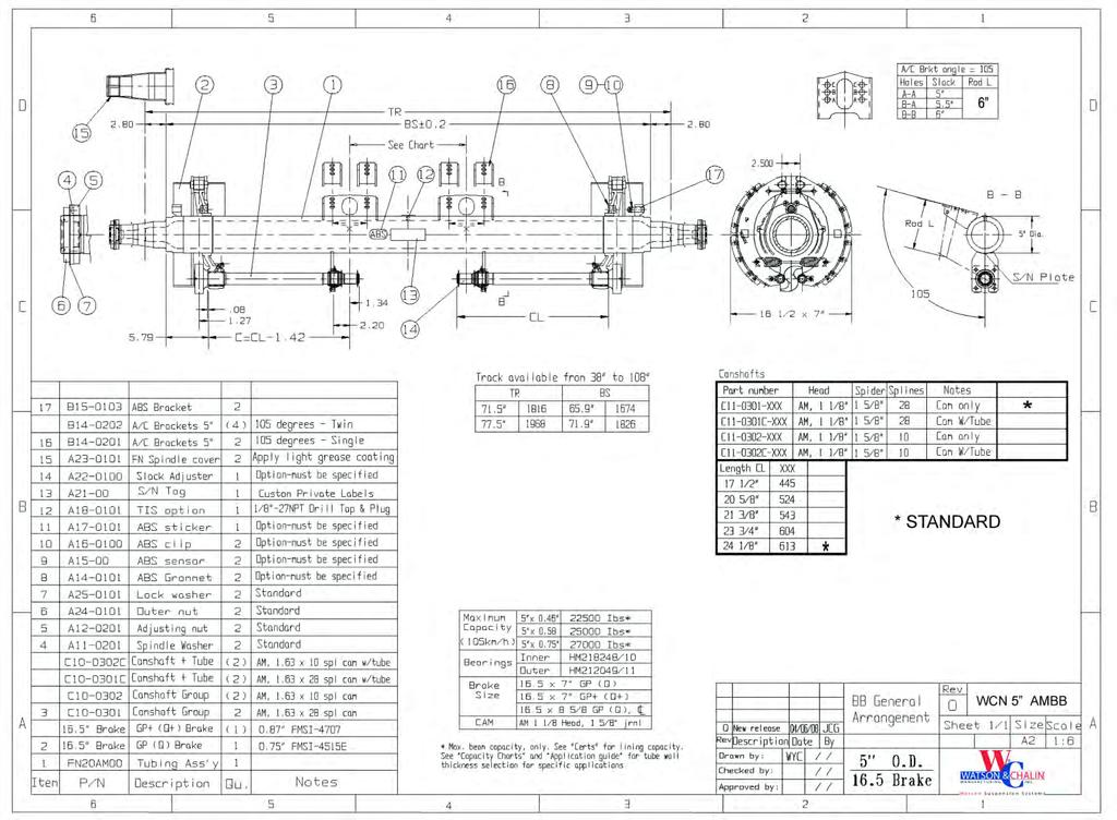
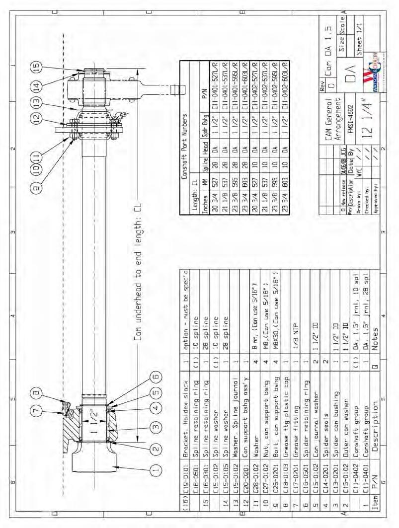
5 Bearing Group: Inner: HM218248, Outer: HM Outside Diameter: 5 - Straight Tube *See capacity charts for details Track lengths 71.5 (standard) 77.5 (standard) Other tracks also available (38 to 108 ) Brakes (Refer to: Brake Lining Certification List) 16 ½ x 7 quick change, Q, FMSI-4515E 16½ x 7 quick change, Q+, FMSI ½ x 8 5/8 quick change GP, FMSI ¼ x 7 ½ quick change DA, FMSI-4692 ABS Bracket is standard - in the SAE recommended position. Tire Inflation Spindle preparation is standard - fits PSI, Tiremax and Airgo hardware Model: WCN Tube wall Max. Capacity Mechanical susp n* Max. Capacity Air susp n* ,000 lbs (normal service) 22,500 lbs (normal service) ,000 lbs (Normal service) 25,000 lbs (normal service) Hub and Drum Assemblies All standard North American N type products will assemble to the WCN spindle. Parts X- Reference See Reference Information section
6 WCN 5 O.D. BRGS: HM = HM W&C AXLE CAPACITY RATING NORMAL SERVICE (See Notes) SPRING SUSPENSION TUBE WALL AIR RIDE SUSPENSION TUBE WALL THIS IS NOT A CERTIFICATION ( FOR INFORMATION ONLY) SPRING MOMENT AXLE BEAM CAPACITY AXLE BEAM CAPACITY AXLE BEAM CAPACITY AXLE BEAM CAPACITY SPINDLE TYPE TRACK (INCHES) SEATS (INCHES) ARM (INCHES) GAWR. (lbs.) GAWR. (lbs.) GAWR. (lbs.) GAWR. (lbs.) WCN ,000 27,000 25,000 25,000 WCN ,320 27,000 24,320 25,000 WCN ,640 27,000 23,640 25,000 WCN ,990 26,800 22,990 25,000 WCN ,380 26,100 22,380 24,870 WCN ,800 25,400 21,800 24,230 WCN ,240 24,700 21,240 23,610 WCN ,720 24,100 20,720 23,030 WCN ,220 23,500 20,220 22,480 WCN ,740 23,000 19,740 21,950 WCN ,290 21,440 WCN ,000 27,000 25,000 25,000 WCN ,320 27,000 24,320 25,000 WCN ,640 27,000 23,640 25,000 WCN ,990 26,800 22,990 25,000 WCN ,380 26,100 22,380 24,870 WCN ,800 25,400 21,800 24,230 WCN ,240 24,700 21,240 23,610 WCN ,720 24,100 20,720 23,030 WCN ,220 23,500 20,220 22,480 WCN ,740 23,000 19,740 21,950 WCN ,290 21,440 NOTES: 1. Ratings are for spring or air suspensions used in normal service. 2. High torsion single point spring suspensions are considered same as air suspensions. 3. For off-road use, find the rating above, then use the next heavier wall. 4. Special applications: call Watson & Chalin for technical assistance
7
8
9 WCN6D 6 DROP CENTER AXLE BEARINGS: HM HM WATSON & CHALIN CAPACITY Air Ride SUSPENSION RATING for AIR RIDE SUSPENSIONS TUBE WALL SPINDLE TYPE THIS IS NOT A CERTIFICATION ( FOR INFORMATION ONLY) TRACK (INCHES) SPRING SEATS (INCHES) MOMEN T ARM (INCHE S) AXLE BEAM CAPACITY GAWR. (lbs.) AXLE BEAM CAPACITY GAWR. (lbs.) WCN ,500 25,000 WCN ,850 24,320 WCN ,230 23,640 WCN ,650 22,990 WCN ,100 22,380 WCN ,580 21,800 WCN ,080 21,240 WCN ,610 20,720 WCN ,160 20,220 WCN ,730 19,740 WCN ,500 25,000 WCN ,850 24,320 WCN ,230 23,640 WCN ,650 22,990 WCN ,100 22,380 WCN ,580 21,800 WCN ,080 21,240 WCN ,610 20,720 WCN ,160 20,220 WCN ,730 19,740 NOTES: 1. Ratings are for air suspensions used in normal service. 2. For off-road use, find the rating above, then use the next heavier wall. 3. Special applications: call Watson & Chalin for technical assistance
10
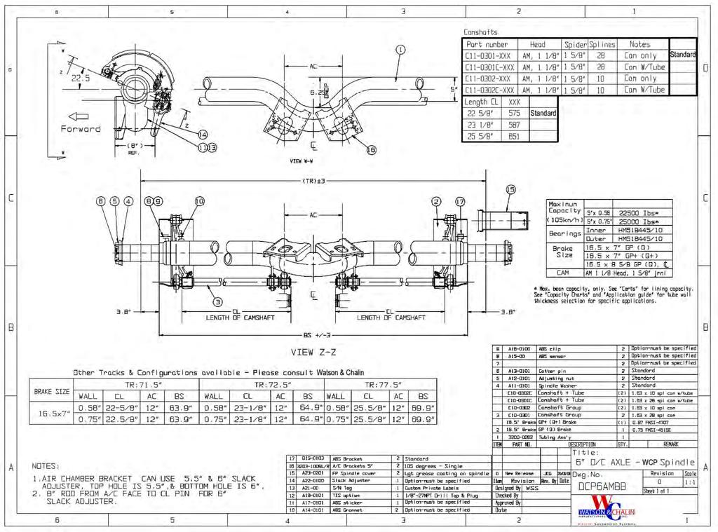
11 Model: WCP Bearing Group: Inner: HM518445, Outer: HM Outside Diameter: 5 Straight Tube Tube wall Max. Capacity Mechanical susp n* Max. Capacity Air susp n* ,000 lbs (normal service) 22,500 lbs (normal service) ,000 lbs (Normal service) 25,000 lbs (normal service) * See capacity charts for details Outside Diameter: 5 ¾ Straight Tube Tube wall Max. Capacity Mechanical susp n* Max. Capacity Air susp n* ,000 lbs (normal service) 25,000 lbs (normal service) Track lengths 71.5 (standard) 77.5 (standard) Other tracks also available (38 to 108 ) Brakes (Refer to: Brake Lining Certification List) 16 ½ x 7 quick change, Q, FMSI4515E 16 ½ x 7 quick change, Q+, FMSI ½ x 8 5/8 quick change GP, FMS I ¼ x 7 ½ quick change DA, FMSI4692 ABS Bracket is standard in the SAE position Tire Inflation Spindle preparation is standard fits PSI, Tiremax and Airgo hardware Hub and Drum Assemblies All standard North American P type products will assemble to the WCP spindle. Parts XReference See Reference Information section
12
13 WCP 5 O.D. BRGS (2) HM AXLE CAPACITY RATING NORMAL SERVICE (See Notes) THIS IS NOT A CERTIFICATION ( FOR INFORMATION ONLY) SPINDLE TYPE TRACK (INCHES) SPRING SEATS (INCHES) MOMENT ARM (INCHES) TUBE WALL Spring Suspension Air Ride Suspension AXLE BEAM CAPACITY GAWR. (lbs.) AXLE BEAM CAPACITY GAWR. (lbs.) AXLE BEAM CAPACITY GAWR. (lbs.) AXLE BEAM CAPACITY GAWR. (lbs.) WCFP ,000 27,000 25,000 25, ,320 27,000 24,320 25, ,640 27,000 23,640 25, ,990 26,800 22,990 25, ,380 26,100 22,380 24,, ,800 25,400 21,800 24, ,240 24,700 21,240 23, ,720 24,100 20,720 23, ,220 23,500 20,220 22, ,740 23,000 19,740 21,950 WCFP ,000 27,000 25,000 25, ,320 27,000 24,320 25, ,640 27,000 23,640 25, ,990 26,800 22,990 25, ,380 26,100 22,380 24, ,800 25,400 21,800 24, ,240 24,700 21,240 23, ,720 24,100 20,720 23, ,160 23,500 18,160 22, ,730 19,740 17,730 21,950 WCFP ,500 25, ,320 27, ,640 27, ,990 26, ,380 26, ,800 25, ,240 24, ,720 24, , , Call Watson & Chalin for technical assistance. Call Watson & Chalin for technical assistance. NOTES: 1. Ratings are for spring or air suspensions used in normal service. 2. High torsion single point spring suspensions are considered same as air suspensions. 3. For off-road use, find the rating above, and then use the next heavier wall.
14 Model: WCPX676D Bearing Group Inner: HM Outer: HM Outside Diameter: 5 Drop Center & Camel Back Tube: 6 drop. (8 and 9 drops also available) Tube wall Maximum capacity* 0.58 (X= s 5) 22,500 lbs (normal service) 0.75 (X= s 6) 25,000 lbs (normal service) *See capacity charts for details Track lengths 71.5 (standard) 77.5 (standard) Other tracks available please consult Watson & Chalin Sales and Technical support. Brakes 16 ½ x 7 quick change, FMSI ½ x 7 quick change, GP+ (Q+), FMSI4707 ABS Bracket is standard in the SAE position Tire Inflation Spindle preparation for PSI, Tiremax and Airgo is standard. Cam position Ahead of axle Behind the axle Cam Length See specific model drawing Hub and Drum Assemblies All standard North American P type products will assemble to spindle. Parts XReference See Reference Information section
15
16
17 Brake Lining Certifications on Watson & Chalin Axles Lining Marerial Manufacturer Brake size (inches) FMSI # Tire Loaded Radius (inches) Spring Brake Size (inches²) Auto-Slack Arm Length (inches) Rating (lbs) Country / Continent Certification PL133 Fuwa 16.5 x E ,000 USA,Canada FMVSS121/CMVSS121 PL133 Fuwa 16.5 x E N/R (1) Type tonnes (2) Australia ADR Schedule-4, SARN#35665 MB21 Carlisle 16.5 x E ,000 USA,Canada FMVSS121/CMVSS121 PL244 Fuwa 16.5 x E ,000 USA,Canada FMVSS121/CMVSS121 PL133XT Fuwa 16.5 x ,000 USA,Canada FMVSS121/CMVSS121 PL244 Fuwa 16.5 x 7+(3) ,000 USA,Canada FMVSS121/CMVSS121* PL244 Fuwa x ,000 USA,Canada FMVSS121/CMVSS121 Notes: 1- N/R = Not required for this certification 2- Metric tonnes x 7 is Q+ REV


18 Air Chamber Spacing (Inches) AC BRAKE SIZE TRACK CL WCN WCP x x N/A x N/A x N/A x N/A x N/A x N/A x N/A x N/A 16 ½ x ½ x ½ x ½ x ½ x ½ x ½ x ½ x ½ x ½ x ½ x 8 5/ ½ x 8 5/ ½ x 8 5/ ½ x 8 5/ ½ x 8 5/ ½ x 8 5/ ½ x 8 5/ ½ x 8 5/ ½ x 8 5/ ½ x 8 5/ Notes: 16.5 x 8 5/8 is a centerline brake -same spider position as 16.5 x 7 Type 2424 = 7.5 O.D. Type 3030 = 8.31 O.D.
19 Axle Options ABS Sensors Installed: Wabco Haldex Bendix Other Slack Adjusters: Haldex Bendix Watson & Chalin - BTC Bearings: Watson & Chalin standard Timken Stemco Others Seals: Watson & Chalin standard SKF C/R Stemco Others Hub Cap: Watson & Chalin Standard Stemco Others Dust Shield Air Chambers and Spring Brakes Watson & Chalin BTC Others 10 spline camshafts: (28 spline standard) Camshaft Enclosures Notes: Total axle price varies according to the options. Watson & Chalin Standard is usually the best priced option. New options can be added upon request when quantities/price/availability are suitable.
20 WCN Axle 12.25" Brake Part Number X-Reference WCN Spindle: Threads 2 5/8"-16 UNS 2A Fuwa FN Hendrickson HN Meritor TN, TQ Spicer (Dana) D22, K22 IMT F22 Bearings: HM Outer HM Inner Brake shoes: 12 1/4" X 7 1/2" 0.715: Standard FMSI 4692 Fuwa DA Meritor Q Spicer Fast Change IMT TIME Camshafts: Standard Lining: GP Std 1 1/2" Cam Bushing, 28 splines Manufacturer Fuwa IMT Meritor Euclid 20 3/4" Left C L LH R E /4" Right C R RH R E /8" Left C L N/A N/A N/A 21 1/8" Right C R N/A N/A N/A 23 3/8" Left C L LH R E /8" Right C R RH R E /4" Left C L N/A N/A E /4" Right C R N/A N/A E Repair Kit: N/A 2028 R E-2469 Fuwa / NEW Fuwa / OLD IMT Meritor Euclid Spider Bushing C N/A E-759/807 Spider Seal C M1105 E-1416 Cam bushing C N/A A G-1151 E-1318AHD Hub Seals Stemco C/R Out-Runner Timken 6" 0D x 4 5/8" ID seal Pro 859 WB116GST ring Classic NLGI#2 Grease Hub Cap Bolts: (6) 5/16" NC Bolts on 5 1/2" BCD Notes: 1- Rollers, anchor pins, springs, snap rings, etc. are all industry standard. 2- Above supplied for information only. Please measure parts before installing. 3- N/A = Not available Options: Many options are available - Consult Watson & Chalin Customer Service.
21 WCN Axle 16.5" Brake Part Number X-Reference WCN Spindle: Threads 2 5/8"-16 UNS 2A Fuwa FN Hendrickson HN Meritor TN, TQ Spicer (Dana) D22, K22 IMT F22 Bearings: HM Outer HM Inner Brake shoes: 16 1/2" X 7" 0.75: Standard 0.88" Thick FMSI 4515E 4707 Fuwa GP GP+ Meritor Q Q+ Spicer Fast Change XL IMT TIME SL Camshafts: GP & GP+, 1 5/8" Cam Head Journal, 28 Spline Manufacturer Fuwa / NEW Fuwa / OLD Spicer/Dana Meritor Euclid 17 1/2" Left C L N/A M16WKL R E /2" Right C R N/A M16WKR R E /8" Left C L L M16WKL R E /8" Right C R R M16WKR R E /8" Left C L N/A M16WKL N/A N/A 21 3/8" Right C R N/A M16WKR N/A N/A 23 3/4" Left C L N/A M16WKL R E /4" Right C R N/A M16WKR R E /8" Left C L L M16WKL R E /8" Right C R R M16WKR R E Repair Kit: N/A N/A R E-9790A Fuwa / NEW Fuwa / OLD Spicer/Dana Meritor Euclid Spider Bushing C M16HD106 R E-9789 Spider Seal C M16HH103 R E-3991 Cam bushing C N/A A G-1151 E-1318AHD Hub Seals Stemco C/R Out-Runner Timken 6" 0D x 4 5/8" ID seal Pro 859 WB116GST ring Classic NLGI#2 Grease Hub Cap Bolts: (6) 5/16" NC Bolts on 5 1/2" BCD Notes: 1- Rollers, anchor pins, springs, snap rings, etc. are all industry standard. 2- Above supplied for information only. Please measure parts before installing. 3- N/A = Not available Options: Many options are available - Consult Watson & Chalin Customer Service.
22 WCP Spindle: Threads 3.48"-12 UN-2A Fuwa FP Hendrickson HP Meritor TP Spicer (Dana) P22 IMT F24 Bearings: HM Outer HM Inner Brake shoes: 16 1/2" X 7" Standard Thick FMSI Fuwa GP GP+ Meritor Q Q+ Spicer Fast Change XL IMT TIME SL Camshafts: GP & GP+, 1 5/8" Cam Head Journal, 28 Spline WCP Axle 16.5" Brake Part Number X-Reference Manufacturer Fuwa / NEW Fuwa / OLD Spicer/Dana Meritor Euclid 17 1/2" Left C L N/A M16WKL R E /2" Right C R N/A M16WKR R E /8" Left C L L M16WKL R E /8" Right C R R M16WKR R E /8" Left C L N/A M16WKL N/A N/A 21 3/8" Right C R N/A M16WKR N/A N/A 23 3/4" Left C L N/A M16WKL R E /4" Right C R N/A M16WKR R E /8" Left C L L M16WKL R E /8" Right C R R M16WKR R E Repair Kit: N/A N/A R E-9790A Fuwa / NEW Fuwa / OLD Spicer/Dana Meritor Euclid Spider Bushing C M16HD106 R E-9789 Spider Seal C M16HH103 R E-3991 Cam bushing C N/A A G-1151 E-1318AHD Hub Seals Stemco C/R Out-Runner Timken 6" 0D x 4 5/8" ID seal Pro 859 WB116GST ring Classic NLGI#2 Grease Hub Cap Bolts: (6) 5/16" NC Bolts on 5 1/2" BCD Notes: 1- Rollers, anchor pins, springs, snap rings, etc. are all industry standard. 2- Above supplied for information only. Please measure parts before installing. 3- N/A = Not available Options: Many options are available - Consult Watson & Chalin Customer Service.
23 Oil and grease suggested change intervals: AXLE LUBRICATION Varying loads and driving conditions will affect the service interval requirements. This chart is a generally accepted guide. Always work in a clean area and clean all parts with proper solvents before use. Never refill the hub with used oil. Contaminated lubricants can quickly destroy the entire assembly. TIME or DISTANCE OIL GREASE BRAKES COMPONENTS 1,000 miles 1,600 km Check the oil level and replace the oil if it is contaminated. Check for leaks. Replace oil and seal if hub has been removed. See the "Add" and "Full" rings on the hub cap 12,000 miles 19,200 km Check brake adjustment 30,000 miles 48,00 km or six months 100,00 miles 160,000km or every year Varies Heavy Duty Use (On/Off Road) Change the oil Heavy Duty Use (On/Off Road) Grease the bearings Normal Use Normal Use Change the oil Grease the bearings Consult the semi-fluid synthetic grease Manufactrurer for recommendations. Also replace this grease if the hub is removed. Check wear in the linings, the cams, and the spider bushings. Grease the brake actuating Lubricants: CAUTION: Do not mix lubricants types. The following GREASE properties are recommended Soap type - Lithium Complex or Equivalent Dropping point - 446ºF (230ºC) Minimum Consistency - NLGI No. 2 or No.1 Additives - Corrosion & Oxidation Inhibitors, EP optional Base Oil - Solvent Refined Petroleum oil The following Oil properties are recommended Gear Oil API GL-5 Performance level SAE 90 SAE 75W, SAE 140 Normal Duty SAE 80W Extreme cold environment Extreme hot environment
24 FASTENER TORQUE SPECIFICATIONS Description Thread Grade Torque Cam bracket bolts: 3/ ft-lbs, 55Nm 10mm ft-lbs, 55Nm Hub Cap 5/16-18UNC 5 15 ft-lbs, 28Nm Dust Shield 5/16 18UNC 5 15 ft-lbs, 28Nm Air Chambers Type 9, 12, 16 7/16-14UNC N/A ft-lbs, 40-55Nm Type 20, 24, 30 5/8-11UNC N/A ft-lbs, Nm Spindle nuts; see Wheel Bearing Adjustment Procedures TMC RP618


25 Recommended Practice RP 609B VMRS , SELF-ADJUSTING AND MANUAL BRAKE ADJUSTER REMOVAL, INSTALLATION AND MAINTENANCE PREFACE The following Recommended Practice is subject to the Disclaimer at the front of TMC s Recommended Maintenance Practices Manual. Users are urged to read the Disclaimer before considering adoption of any portion of this Recommended Practice. PURPOSE AND SCOPE The purpose of this Recommended Practice (RP) is to provide information regarding the removal, installation, operation, maintenance, and selection of heavy-duty vehicle manual and self-adjusting brake adjusters. INTRODUCTION In an S-cam type foundation brake, the final link between the pneumatic system and the foundation brake is the brake adjuster. The arm of the brake adjuster is fastened to the push rod of the chamber with a clevis and the spline end is installed on the brake camshaft. Primarily, the brake adjuster is a lever that converts the linear force of the air chamber push rod into a torque which turns the brake camshaft and applies the brakes. Two types of brake adjusters are in use: manual type brake adjusters, which periodically require a manual adjustment; and self-adjusting brake adjusters, which automatically adjust during normal service braking applications. All brake adjusters use the worm and gear principle and fundamentally differ only in their torque limit specification. NOTE: Manual and self-adjusting brake adjusters are for brake adjustment and will not compensate for normal wear characteristics and maintenance requirements associated with foundation brakes. BALL INDENT TYPE SLACK ADJUSTER POSITIVE LOCK TYPE SLACK ADJUSTER LOCK SCREW BODY LOCKING COLLAR ADJUSTING HEX WORM SHAFT ADJUSTING HEX WORM GEAR Fig. 1: Manual Brake Adjusters 2002 TMC/ATA RP 609B 1 Issued 3/80 Revised 3/2002
26 MANUAL BRAKE ADJUSTERS Manual brake adjusters contain four basic components: the body, worm gear, worm shaft, and locking screw or collar. See Fig. 1. The worm shaft of a brake adjuster incorporates an external adjusting hex. Turning the adjusting hex rotates the worm shaft which turns the worm gear and brake cam shaft, thus spreading the brake shoes and reducing drum-to-lining clearance. Light to medium gross axle weight rating (GAWR) vehicles utilize either a spring-loaded locking sleeve or a lock ball indent adjustment lock to prevent the worm shaft from backing off. Higher torque-rated brake adjusters use the lock ball or plunger and worm shaft indent principle adjustment lock. The lock ball or plunger must engage the worm shaft indent after the adjustment is completed. An audible metallic click can be heard when engagement is made. SELF ADJUSTING BRAKE ADJUSTERS While self-adjusting brake adjuster designs vary in the manner in which they are installed and operate, all are designed to automatically maintain a predetermined drum-to-lining clearance or brake chamber stroke. Some self-adjusting brake adjusters adjust upon the brake application stroke, others adjust upon release. Self-adjusting brake adjusters should not have to be manually adjusted while in service. However, manual adjustments can be made temporarily to get a vehicle to a maintenance facility for inspection and repair, if necessary.! CAUTION Self-adjusting brake adjusters do not eliminate or reduce the need for periodic inspection and maintenance of the adjuster components and attaching hardware. Self-adjusting brake adjusters should never be operated as a manual adjuster, if the self-adjusting function is not operating properly. BRAKE ADJUSTER REPLACEMENT When replacing a brake adjuster, it is recommended that the replacement be of the same size as the original equipment. All self-adjusting brake adjusters on a vehicle should be made by the same manufacturer. To identify the proper replacement, the following slack adjuster key dimensional checks are recommended. Arm length (center of spline to center of arm hole to be used). Type, width, number, and diameter of splines. Clevis pin diameter (do not drive out bushing to accommodate a larger clevis pin). Brake chamber push rod size (5/8" or 1/2"). If offset configuration, determine the offset dimension (right or left side). BRAKE ADJUSTER REMOVAL AND INSTALLATION : To avoid possible injury, proper precautions must be taken to prevent automatic actuation of the brake chambers while removing or installing slack adjusters. Always block the wheels or mechanically secure the vehicle. Spring brakes must be mechanically caged. All brakes should be released. A. Manual Brake Adjuster Removal 1. Remove the brake chamber push rod clevis pin. 2. Remove the retaining mechanism from the end of the brake camshaft. 3. Rotate the adjusting hex to back the brake adjuster out of the clevis. 4. Remove the brake adjuster from the spline end of the brake cam shaft. B. Manual Brake Adjuster Installation 1. Install the brake adjuster on the cam shaft so the adjustment hex and grease fitting (if so equipped) are accessible for servicing. 2. Align the brake adjuster arm with center of the push rod clevis. Install the clevis pin and secure it with a new cotter pin. 3. Check to be sure the angle formed by the brake adjuster arm and the brake chamber push rod is greater than 90 when the brake adjuster is in the released position. 4. Install the brake adjuster retaining mechanism on the end of the brake cam shaft, being sure to shim it to less than inch of end play. 5. Tighten the jam nut on the push-rod-to-clevis attachment (1/ in. Ibs. 5/ in. Ibs.). 6. After installation, make certain there is adequate clearance in both the fully applied and fully released positions. Check to ensure that all brake adjusters rotate freely and without binding. 7. Adjust the brakes by following the procedure in the section entitled BRAKE ADJUSTMENT PROCEDURE TMC/ATA RP 609B 2

27 Fig. 2: Self-Adjusting Brake Adjuster Types C. Self-Adjusting Brake Adjuster Removal 1. Remove the clevis and link pins and the anchor bracket nut or pawl, if necessary (see Fig. 2). a.style A Remove the clevis and link pins. b.style B Remove the retaining ring quick connect yoke. c. Style C Remove the pawl, clevis, and link pins. d.style D Remove the clevis pin and anchor bracket nuts. 2. Remove the retaining mechanism from the end of the brake cam shaft. 3. Rotate the adjusting mechanism to back the self-adjusting brake adjuster out of the clevis, if necessary. 4. Remove the self-adjusting brake adjuster from the spline end of the brake cam shaft. NOTE: If a manual brake adjuster is being removed to be replaced with a self-adjusting brake adjuster, the manual or threaded clevis must be removed from the brake chamber push rod (with Style D self-adjusting brake adjuster, the existing clevis is used and additional anchor bracket hardware is required). Leave the jam nut on the push rod. D. Self-Adjusting Brake Adjuster Installation 1. Ensure that the brake chamber is installed in the bracket holes appropriate for the selfadjusting brake adjuster arm length. 2. Clean the camshaft splines. 3. Coat the camshaft splines and the end of the brake chamber push rod with an anti-seize type product. 4. Install either a quick connect nut or threaded clevis on the brake chamber push rod per the manufacturer s recommendations. Some manufacturers offer both quick connect and threaded clevises. 5. Install the self-adjusting brake adjuster on the camshaft. 6. Install the self-adjusting brake adjuster retaining mechanism on the end of the brake cam shaft, being sure to shim it to less than inch of end play. 7A. Rotate the adjusting mechanism to either install a clevis and link pin or to connect the clevis with a quick connect nut (see Fig. 2, Styles A, B, and C). 7B. For Style D, install the anchor bracket loosely and then rotate the adjusting mechanism to install the clevis pin. 8A. Using the correct gauge or template, (see Fig. 2, Styles A, B, and C) check for the proper mounting angle. Adjust the clevis for the correct angle, if necessary TMC/ATA RP 609B 3
28
29
30
31 spring pressure is relieved from the clevis. Work the adjusting nut 1/4 turn back and forth while watching for cam rotation. If you have 1/8 to 1/4 turn of play without the cam rotating, the manual brake should be replaced. Repeat this procedure every 1/4 turn of the adjusting nut to check the whole gear set. Self-Adjusting Brake Adjuster Failure Analysis If the power stroke is at or more than the maximum stroke, measure free stroke and check/inspect the adjuster components and attaching hardware to determine if the slack adjuster is operational. FREE STROKE MEASUREMENT Free stroke is the amount of brake arm movement required to move the brake shoes against the drum. To measure free stroke, perform the following: 1. With the brakes released, measure from the brake chamber face to the center of the clevis pin. 2. With a lever, pry the brake adjuster arm until the brake shoes contact the drum and measure the brake adjuster movement (see Fig. 6). 3. The difference between the brake released and applied measurements is the free stroke. The free stroke should be 3/8" - 5/8". If the free stroke is in the correct range, the out of spec stroke is due to a foundation brake problem. Check for missing or worn components, cracked brake drums, or improper lining-todrum contact. If the free stroke is greater than recommended, a self-adjusting brake adjuster function test should be performed. SELF-ADJUSTING BRAKE ADJUSTER FUNCTION TEST 1. Remove the pawl, then rotate the adjusting mechanism at least one complete turn as if backing off the brake adjustment (see Fig. 2, Style C). The pawl must be installed properly and tightened to ft-lbs after backing off the adjuster. 2. Apply the brakes several times and observe whether the adjustment mechanism is rotating in the direction needed to reduce brake chamber pushrod stroke. If the adjusting mechanism does not rotate, the brake adjuster should be replaced. 3. Check back-off torque by rotating the adjusting hex as follows (see Fig. 2): Style A: Minimum 15 ft-lbs counter clockwise (CCW) Style B: Minimum 15 ft-lbs CCW Style C: Less than 45 in-lbs CCW (pawl removed) Style D: Minimum 15 ft-lbs CCW Consult the manufacturer for more information. PREVENTIVE MAINTENANCE Every month, 8,000 miles, or 300 operating hours, check brake chamber push rod travel;chamber stroke should be in compliance with the maximum allowable adjusted strokes indicated in Table 1, without the brakes dragging or the pushrod binding. Adjust manual slacks if necessary. Due to different operating conditions, adjustments may be necessary at earlier intervals. Every 6 months, 50,000 miles, or 1,800 operating hours, lubricate all brake adjusters and clevis pins with manufacturer s recommended lubricant. Check for worn clevises, clevis pins, clevis pin bushings, and worn or broken control arm/attaching brackets. Failure to replace worn, broken, or disconnected components will increase chamber stroke. Lubrication and inspection may be necessary at earlier, intervals due to different operating conditions TMC/ATA RP 609B 7
32 Recommended Practice RP 618 VMRS 018 WHEEL BEARING ADJUSTMENT PROCEDURES PREFACE The following Recommended Practice is subject to the Disclaimer at the front of TMC s Recommended Maintenance Practices Manual. Users are urged to read the Disclaimer before considering adoption of any portion of this Recommended Practice. OBJECTIVE The goal of this Recommended Procedure is to achieve a verifiable wheel bearing end play of 0.001" to 0.005" (0.025 mm to mm). SCOPE The following service procedures apply to steer, drive, and trailer axle assemblies using conventional double nut or single nut systems. Follow these service procedures carefully to prevent premature wheel end component failure and increase seal and bearing life. ABS (anti-lock braking systems) and traction control systems with wheel end sensing require precise bearing adjustment to function properly. This Recommended Practice details proper service procedures for D-type, bendable-type, and doweltype spindle nut washers. NOTE: For single nut self-locking systems, consult manufacturers instructions. If you have a system that differs from what is indicated in this procedure, consult the vehicle manufacturer s recommended procedure. WARNING: Never work under a unit supported by only a jack. Always support the vehicle with stands. Block the wheels and make sure the unit will not roll before releasing brakes. CAUTION: If your axle is equipped with spoke wheels and the rim clamps have been disassembled to remove the tire and rim assembly, the tire and rim assembly must be reinstalled and the rim clamps properly torqued BEFORE adjusting the wheel bearings. Failure to do this may result in improper wheel bearing adjustment. REFERENCES TMC RP 622,Wheel Seal and Bearing Removal, Installation and Maintenance. PROCEDURES Step 1: Lubricate the bearing with clean axle lubricant of the same type used in the axle sump or hub assembly. IMPORTANT (a) In oil bath systems that rely on differential fill to provide lubricant to the wheel seals, do not pack bearings with grease before installation. Grease will temporarily restrict or prevent the proper circulation of axle lubricant and may contribute to wheel seal failure. (b) Never use an impact wrench to adjust wheel bearings. Step 2: After the wheel hub and bearings are assembled on the spindle or axle tube, torque the inner (adjusting) nut to 200 lbf ft (271 N m) while rotating the wheel hub assembly. Refer to Table 1 at the end of this Recommended Practice. Step 3: Back off the inner (adjusting) nut one full turn. Rotate the wheel. Step 4: Re-torque the inner (adjusting) nut to 50 lbf ft (68 N m) while rotating the wheel hub assembly. Refer to Table 1 at the end of this Recommended Practice. Step 5: Back off the inner (adjusting) nut. Refer to Table 1 at the end of this Recommended Practice for the proper back-off amount. Step 6: Install the locking washer TMC/ATA RP Issued 3/93
33 If dowel pin and washer (or washer tang and nut flat) are not aligned, remove the washer, turn it over and reinstall. If required, loosen the inner (adjusting) nut just enough for alignment. IMPORTANT Never tighten the inner (adjusting) nut for alignment at this point of the procedure. This may pre-load the bearing and cause premature failure. Step 7: Install and torque the outer (jam) nut. Refer to Table 1 at the end of this Recommended Practice for proper torque values. NOTE: This adjustment allows the wheel to rotate freely with 0.001" to 0.005" (0.025 mm to mm) end play. Step 8: Verify end play with a dial indicator. Wheel end play is the free movement of the tire and wheel assembly along the spindle axis. (a) Make sure the brake drum-to-hub fasteners are tightened to the manufacturers specifications. (b) Attach a dial indicator with its magnetic base to the hub or brake drum. (c) Adjust the dial indicator so that its plunger or pointer is against the end of the spindle with its line of action approximately parallel to the axis of the spindle. See Fig. 1. (d) Grasp the wheel assembly at the 3 o clock and 9 o clock positions. Push the wheel assembly in and out while oscillating it to seat the bearings. Read bearing end play as the total indicator movement. NOTE: If end play is not within specification, readjustment is required. Step 9: RE-ADJUSTMENT PROCEDURE Excessive End Play If end play is too loose, remove the outer (jam) nut and pull the washer away from the inner (adjusting) nut, but not off the spindle. Tighten the inner (adjusting) nut to the next alignment hole of the washer. Reassemble the washer and re-torque the outer (jam) nut. Refer to Table 1 for torque values. Verify end play with a dial indicator. Insufficient End Play If end play is not present, remove the outer (jam) nut and pull the washer away from the inner (adjusting) nut, but not off the spindle. Loosen the inner (adjusting) nut to the next alignment hole of the washer. Reassemble the washer and re-torque the outer (jam) nut. Refer to Table 1 for torque values. Verify end play with a dial indicator. FINE TUNING THE ADJUSTMENT If, after performing the readjustment procedures, end play is 0.004" " (0.102 mm mm) range, repeat the appropriate procedures, removing the washer from the spindle, tighten or loosen With indicator mounted at bottom With push/pull indicator at mounted sides of at bottom drum push/pull at sides of drum (a) with tire assembly (b) without tire assembly Fig. 1: Dial Indicator Set-Up 2003 TMC/ATA RP 618-2
34 the inner adjusting nut the equivalent of 1/2 of an alignment hole of the washer, or reversing the alignment washer, and reinstalling it onto the spindle. Reassemble and re-torque the outer (jam) nut. Refer to Table 1 for torque values. Verify end play with a dial indicator. NOTE: Bendable-type washer lock only: Secure nuts by bending one wheel nut washer tang over the inner and outer nut. Bend the tangs over the closest flap perpendicular to the tang. See Fig. 2. CAUTION: Before operating the unit, the wheel hub cavities and bearings must be lubricated to prevent failure. For final wheel end assembly refer to TMC RP 622. SINGLE NUT ADJUSTMENT Adjusting nut TANG-TYPE LOCK ADJUSTING NUT Nut lock Bend tangs perpandicular to closest flat SPINDLE WASHER-TYPE ADJUSTING NUT Wheel bearing adjusting nut (inner) Dowel pin Cotter pin D Washer Outer nut Wheel bearing adjusting nut (inner) Outer nut Spindle washer D Type Tang Type Dowel Type Fig. 2: Adjusting Nut Identification and Installation 2003 TMC/ATA RP 618-3
35 TABLE 1 WHEEL BEARING ADJUSTMENT PROCEDURE STEP 1: Lubricate the wheel bearing with clean axle lubricant of the same type used in the axle sump or hub assembly. Note: Never use an impact wrench when tightening or loosening lug nuts or bolts during the procedure. INITIAL INITIAL FINAL BACK OFF JAM NUT TORQUE ACCEPTABLE ADJUSTING BACK OFF ADJUSTING AXLE THREADS FINAL NUT TORQUE END PLAY NUT NUT TYPE PER INCH BACK OFF SIZE SPECIFICATIONS TORQUE TORQUE STEP 2 STEP 3 STEP 4 STEP 5 STEP 6 STEP 7 STEP /6 Turn * Install Cotter Pin to Lock Axle Nut in Position Steer 18 1/4 Turn * (Front) 200 lb ft (271 N m) While Rotating Wheel One Full Turn 50 lb ft (68 N m) While Rotating Wheels Non-Drive Drive /2 Turn 1/4 Turn Less Than 2-5/8" (66.7 mm) Dowel Type Washer Tang Type Washer ** lb ft ( N m) lb ft ( N m) lb ft ( N m) 0.001"-0.005" ( mm) As Measured Per Procedure With Dial Indicator Trailer /4 Turn 2-5/8" (66.7 mm) and over lb ft ( N m) * If dowel pin and washer (or washer tang and nut flat) are not aligned, remove the washer, turn it over, and reinstall. If required, loosen the inner (adjusting) nut just enough for alignment. ** Bendable type washer lock only: Secure nuts by bending one wheel nut washer tang over the inner and outer nut. Bend the tangs over the closest flat perpendicular to the tang TMC/ATA RP
36 Recommended Practice RP 631A VMRS 018 RECOMMENDATIONS FOR WHEEL END LUBRICATION PREFACE The following Recommended Practice is subject to the Disclaimer at the front of TMC s Recommended Maintenance Practices Manual. Users are urged to read the Disclaimer before considering adoption of any portion of this Recommended Practice. PURPOSE AND SCOPE The purpose of this Recommended Practice is to offer equipment users recommendations and operational considerations for selecting lubricants for use in wheel end applications. This Recommended Practice applies to Class 3-8 trucks, buses, tractors, and trailers designed for on-highway applications. Outboard Bearing Adjusting Nut Hubcap Lubricant Cavity Hub Wheels Fig. 1: Non-Drive Wheel End Seal Inboard Bearing This Recommended Practice applies to only traditionally equipped axles and hubs. This Recommended Practice defines traditionally equipped axles and hubs as wheel ends equipped with two single row, widespread, tapered roller bearing assemblies which are manually adjusted. Other relevant TMC Recommended Practices include: RP 624, Lubricant Fundamentals. RP 709, Hubcap Standardization Bolted- On Type. This Recommended Practice addresses two categories of wheel ends: driven and non-driven. Non-driven wheel ends include steer, dolly, trailer, pusher and tag axles. (See Figures 1 and 2). The lubricant used in the wheel ends can be either petroleum-based or syntheticbased oils or greases. REFERENCE For additional information on wheel bearing adjustment, installation and maintenance, refer to TMC: RP 618, Wheel Bearing Adjustment Procedures. RP 622, Wheel Seal and Bearing Removal, Installation, and Maintenance. Hub Outboard Bearing Adjusting Nuts Drive Axle Shaft Gasket Oil Cavity Wheels Fig. 2: Drive Axle Wheel End Brake Drum Seal Spindle Inboard Bearing 2003 TMC/ATA RP 631A 1 Issued 3/96 Revised 11/1999
37 Fleet managers should also reference original equipment manufacturer (OEM) maintenance and service manuals as appropriate. NON-DRIVEN AXLE LUBRICANT CONSIDERATIONS Non-driven wheel ends can be lubricated effectively with either oil or grease, depending on the fleet application. Both lubricating substances use oil as the lubricating medium. (Refer to RP 624, Lubricant Fundamentals for details.) Fill to oil level line A. Non-Driven Oil-Lubricated Wheel Ends Inspection and Preparation Clean and inspect the wheel end components including all bearings, hubcaps, hub and bearing cups, axle spindle, and fasteners, removing all contaminants and lubricant residue. Replace seal, hubcap gasket, and all questionable parts. For detailed procedures, refer to TMC RP 622. Component Lubrication Pre-lubricate the inner and outer wheel bearing cones with clean lubricant of the same type used in the hub assembly.! CAUTION : Failure to lubricate bearing correctly, and maintain proper lubrication, may result in bearing damage. For additional information refer to TMC RP 618 and RP 622.! CAUTION : In oil bath systems, do not pack bearings with grease before installation. Grease will temporarily restrict or prevent the proper circulation of lubricant and may contribute to wheel seal failure. Hub Fill Procedures: Oil Install the wheel seals as documented in RP 622. Apply lubricant to the bearing journals and bearing cones. Use the same lubricant that will be used to lubricate the system. This will help inhibit fretting corrosion and make assembly easier. Use lifting equipment to align the hub assembly with the spindle taking care not to damage the seal and spindle threads. While the hub is supported/suspended, fill the hub cavity with clean oil and push the hub into position, or push the hub into position and then fill the hub cavity. Install the outer bearing, and adjusting nut systems. Adjust wheel bearings using TMC RP 618 or OEM Maintenance Manual. Verify end play (0.001" to 0.005") with a dial indicator. Fig. 3: Lubrication Fill Oil (Static) Hubcap Considerations: Oil Select the proper vented, bolt-on or threaded hubcap for the application and follow hubcap suppliers instructions for proper attachment to the wheel hub. Fill wheel end assembly through the fill port with the same oil. Allow time for the oil to seep through the outer bearing and fill the hub cavity. Continue to add oil until the oil reaches the oil fill line as indicated on the hubcap. (See Figure 3.) NOTE: For hubcaps with side fill plugs, do not allow the oil to go past the centerline or vent hole.! CAUTION : Overfilling or under filling a wheel hub with lubricant may result in premature component failure. Install center fill or side fill plug. Torque side fill plug to hubcap manufacturer s specifications. Clean-up any over spills that would give the appearance of a leaking hubcap. B. Non-Driven Grease-Lubricated Wheel Ends NOTE: Semi-fluid greases are NLGI 000 and 00. NLGI 0 is a soft grease. All three grades listed above are treated as semi-fluid greases in this RP. Hard greases are defined as NLGI 1, 2, and 3 consistencies in this RP. Inspection and Preparation Clean and inspect the wheel end components including all bearings, hubcaps, hub and bearing cups, axle spindle, and fasteners, removing all contaminants and lubricant residue. Replace seal, hubcap 2003 TMC/ATA RP 631A 2
.")
38 Mandatory Grease Area Fig. 4: Packing of Bearing Cone gasket, and all questionable parts. For detailed procedures, refer to TMC RP 622. NOTE: If retrofitting an oil or grease system with a semi-fluid grease, be sure to note the need for special cleaning instructions, fill procedures and equipment (i.e., vented hubcap). Component Lubrication Pack the inner and outer wheel bearing cones full with grease. Work the grease into the bearing in the direction of the arrow shown in Figure 4 by machine or hand such that the grease goes under the bearing cage toward the cone rib and roller ends. For corrosion prevention, place a light film of grease on all metal components, including the hubcap. Wipe off the excess grease. Install the wheel seals as described in TMC RP 622.! CAUTION : Failure to lubricate bearing correctly and maintain proper lubrication may result in bearing damage. For detailed procedures, refer to TMC RP 618 and RP 622. : If grease packing is done by hand, appropriate protection such as gloves and clothing should be worn to minimize skin contact with the grease.! CAUTION : Overfilling or under filling a wheel hub with lubricant may result in premature component failure. Hub Fill Procedures: Semi-fluid Grease If tires are not mounted, install the hub on the spindle. Take care to not damage the seal. Use lifting equipment to align the hub assembly with the spindle taking care to not damage the seal and spindle threads and push the hub assembly into position. With the hub supported, before installing the outer bearing cone, begin filling from the bottom of the hub cavity. Top-off by placing the pump nozzle above the spindle, and continue pumping grease into the hub cavity. (See Figure 5.) CAGE CUPS CONE ROLLER CUP Cup Small Inside Diameter Fig. 5B: Tapered Bearing Nomenclature Apply Grease Around Adjusting Nut Fig. 5: Semi-Fluid Grease Top Off Procedure Fig 5A: Lubrication Fill Semi-Fluid Grease (No. 00) 2003 TMC/ATA RP 631A 3

39 Maintenance Manual. Verify end play (0.001" to 0.005") with a dial indicator. Before installing the hubcap, apply a coating of grease around the wheel bearing adjustment nut(s). Hubcap Considerations: Semi-fluid Grease Use an appropriate tamper-proof, vented hubcap. These hubcaps prevent gear oils from being accidentally added to grease-filled wheel ends. NOTE: Because of the hubcap s special venting capability and the properties of the semi-fluid grease, do not fill the hubcap with grease. Fig. 5C: Using Template to Hold Lubricant The grease fill amount should be to a 3 o clock and 9 o clock level. This represents 50 percent hub cavity fill. (See Figures 5A and 5B.) NOTE: A template may be used to hold the lubricant in place while filling the hub cavity. (See Figures 5 and 5C.)! CAUTION : Make sure that there are no air-pockets trapped under the grease. If pumping equipment is used, ensure the pump does not aerate the grease. Aeration of the grease may result in underfilling. Install the outer bearing, washers and adjusting nuts. Adjust wheel bearings per TMC s RP 618 or per OEM NOTE: If a metal hub cap is used, it is necessary to coat the interior surfaces with a film of grease. Use special care not to cover the vent with grease. Hub Fill Procedures: Hard Grease Before installing the hub, pack grease into the hub cavity. Fill the circumference of the hub cavity using the bearing races as the proper level guide. (See Figure 6.) Use lifting equipment to align the hub assembly with the spindle taking care to not damage the seal and spindle threads. Push the hub assembly into position. Install the outer bearing, washers and adjusting nuts. Adjust wheel bearings per TMC s RP 618 or OEM Maintenance Manual. Verify end play (0.001" to Fig. 6: Lubrication Fill Greases (Nos. 1,2, & 3) 2003 TMC/ATA RP 631A 4
40 0.005") with a dial indicator. Apply a coating of grease around the adjusting nut(s). Hubcap Considerations: Hard Grease Use an appropriate tamper-proof, hubcap. These hubcaps prevent gear oils from being accidentally being added to grease-filled wheel ends. Follow the recommendation of the seal supplier to determine if the hubcap should be vented or non-vented. NOTE: If a metal hub cap is used, it is necessary to coat the interior surfaces with a film of grease. Use special care not to cover the vent with grease. DRIVEN AXLE LUBRICANT WHEEL END CONSIDERATIONS NOTE: In this Recommended Practice, all driven axles are oil lubricated. Inspection and Preparation If the wheel end is disassembled, clean and inspect the wheel end components including all bearings, axle shafts, hub and bearing cups, axle, and fasteners, removing all contaminants and lubricant residue. Replace seal, axle flange gasket, and all questionable parts. For detail procedures, refer to TMC RP 622. Component Lubrication Pre-lubricate the inner and outer wheel bearing cones with clean lubricant of the same type used in the axle reservoir.! CAUTION : Failure to lubricate bearing correctly and maintain proper lubrication may result in bearing damage. For additional information refer to TMC RP 618 and RP 622.! CAUTION : In oil bath systems, do not pack bearings with grease before installation. Grease will temporarily restrict or prevent the proper circulation of lubricant and may contribute to wheel seal failure. Hub Fill Procedures: Oil Install the wheel seals, as documented in RP 622. Fill hub cavity with oil. Use lifting equipment to align the hub assembly with the spindle taking care to not damage the seal and spindle threads. Push the hub assembly into position. While the hub is supported, fill the hub cavity with clean oil and push into position or push into position and then fill the hub cavity. Install the outer bearing, washers and adjusting nuts. Adjust wheel bearings per TMC s RP 618 or OEM Maintenance Manual. Verify end play (0.001" to 0.005") with a dial indicator. Install the flanged drive axle shaft with a new axle flange gasket. Torque flange nuts to axle manufacturer s specification. Clean-up any over spills that would give the appearance of a leaking system. Oil is supplied directly to the wheel ends at assembly and through the axle tube during operation. To achieve final fill level, each end of the drive axle must be raised a minimum of eight inches for one minute to move the lubricant into the opposite wheel end. Recheck the main sump for the proper oil level and top off the lubricant level, if required. The oil fill level is always to the bottom of the fill plug or hole in the axle reservoir.! CAUTION : Do not pack the drive axle wheel bearings with grease when the wheel ends will be lubricated with oil from the axle differential. (See RP 622 and RP 618.) NOTE: Always check the axle breather to be sure it is operating properly and completely free of dirt and debris. MAINTENANCE AND INSPECTION REQUIREMENTS The following inspection criteria are intended for units whose vocation is strictly on-highway use only. The inspection criteria are not intended for unitized or pre-set wheel ends, refer to systems manufacturer for inspection and service recommendations. These recommendations depend on the proper assembly of the system, including the proper lubricant fill level. A. OIL LUBRICATED WHEEL ENDS INSPECTION CRITERIA Level 1 Simple Inspection (Pre-Trip/In-Service) Walk around vehicle and check wheel-ends for obvious signs of lubricant leakage, such as hubcap gasket and wheel seal areas, oil soaked brake linings. Check for broken or missing components. Any seepage is reason for further inspection and appropriate action. Take appropriate action if leaks or oil soaked brake linings are noted TMC/ATA RP 631A 5
41 NOTE FOR DRIVERS: After making an en route stop, walk around the unit and feel the hubs. If there is any significant differences in temperatures or excessive temperature, contact your maintenance department. When feeling hubs for temperature, seasonal influences should be taken into consideration. If wheel-ends are equipped with a sight glass on the hubcaps, check to ensure the oil is at the proper fill level. NOTE: Oil residue may be present at the vent area. This is an indicator that the system is venting properly. This should not be construed as system leakage. Level 2 100,000 miles or Annual Inspection: For non-driven axles check lubricant level and condition. If lubricant is contaminated replace old lubricant with the same type lubricant. If lubricant condition is good and level is low, fill to the proper level. Check for any signs of leakage at the seal or hubcap gasket areas. Check for oil soaked brake linings. For driven axles, check for any signs of leakage at the seal or axle flange gasket areas. Also check for leaks at hub fill hole if so equipped. Check for oil soaked brake linings. Take appropriate action if leaks or oil soaked brake linings are noted. B. GREASE LUBRICATED WHEEL ENDS INSPECTION CRITERIA Level 1 Simple Inspection (Pre-Trip/In-Service) Walk around vehicle and check wheel-ends for obvious signs of lubricant leakage, such as hubcap gasket and wheel seal areas, grease soaked brake linings. Check for broken or missing components. Any seepage is reason for further inspection and appropriate action. NOTE FOR DRIVERS: After making an en route stop, walk around the unit and feel the hubs. If there is any significant differences in temperatures or excessive temperature contact the maintenance department. When feeling hubs for temperature, seasonal influences should be taken into consideration. Level 2 Detailed External Inspection (Conducted at PM or at least annually) Check wheel-ends for obvious signs of lubricant leakage, such as hubcap gasket and wheel seal areas, grease soaked brake linings. Any seepage is reason for further inspection and appropriate action. Raise the vehicle and check for smooth rolling of wheels. Check for signs of excessive end play in the wheel-end. This does not include removal of the hub cap. NOTE: Leaking grease may not spread over the hub and brake components as with hubs filled with oil. When inspecting for grease leaks the inspection must be done very carefully with the aid of a bright beam of light from a flashlight or droplight. NOTE: Some grease seals will purge very small amounts of grease in normal operation. If there is seepage around the hubcap flange area, take appropriate action to eliminate seepage as directed by your maintenance instructions. If leakage in the seal area is found, remove the wheel end and replace the hubcap gasket, seal and lubricant. Inspect the spindle and bearings for damage and replace if needed. Anything abnormal requires Level 3 Inspection.! CAUTION : A clogged vent can damage the wheel seal allowing internal pressure build up in the wheel end. Level 3 Lube Level Inspection (Per OEM Recommendation) When using grease in a wheel-end the only method to accurately check the lubricant level is by pulling the outer bearing. If using a hard grease, there is no need for a Level 3 Inspection.! CAUTION : Failure to remove the outer bearing may provide a false lubricant level reading. To verify proper lube level the following procedures need to be performed. 1. Before performing any maintenance on the vehicle take appropriate action to ensure the vehicle is safely secured. 2. Remove hubcap, hubcap gasket and inspect hubcap for adequate venting capabilities. 3. Verify wheel-bearing end play for conformance to RP Record end play measurements. CAUTION! : Apply the parking brake, if axle is equipped. This will ensure that the wheel/hub 2003 TMC/ATA RP 631A 6
42 assembly is supported and held steady during removal of the spindle nut and outer bearing. This will eliminate the possibility of spindle, bearing or seal damage due to the cocking or slipping of the wheel-hub assembly.! CAUTION : Care should be taken so the wheel-end assembly is properly supported. 5. Remove adjusting nuts. 6. Remove outer bearing. 7. While maintaining proper support to the wheelend or hub, visually check lube level. In a semi-fluid grease system, if the lubricant flows out of the hub cavity, the hub cavity should be refilled to the 3 o clock and 9 o clock level. This represents 50 percent hub cavity fill. (See Figures 5 and 5A.) In a semi-fluid grease system, if the grease doesn t flow, inspect lubricant condition in the hub cavity. Go to Level 4 Inspection if abnormal conditions are noted. If no abnormal conditions are noted, add grease until it flows out of the hub cavity. NOTE: If changing grease types or brands, contact your lubricant supplier to insure compatibility. 8. Clean bearing and inspect for wear and damage. When reassembling industry standard wheel-ends, assemble per RP 618. NOTE: Manufacturer is defined as the final assembler of the product or the particular system supplier. Level 4 Wheel-end Disassembly Inspection (Complete System Tear-down) If any abnormal conditions are found during inspection Levels 1, 2, or 3, remove wheel-end for inspection. Lube change intervals as determined by the manufacturer dictate when Level 4 service is performed. NOTE: Manufacturer is defined as the final assembler of the product or the particular system supplier. When reassembling industry standard wheel-ends, assemble per RP 622 and RP 618. Seals and gaskets must be replaced. Failed Component Analysis Save prematurely failed parts and lube samples for analysis. The lubricant sample collected should be at least four ounces. A similarly sized new lubricant sample (not previously used) is also required. This will aid in supplier assisted detection and prevention of premature failures. The components history of usage should also be provided (i.e., vehicle s vocation, mileage, maintenance records, and history of inspection and repair/replacement of components such as seals, seal wear rings, lubricant, bearings, etc.). OPERATIONAL CONSIDERATIONS FOR LUBRICANTS Service interval ranges from 100,000 miles to five years in over-the-road service, depending on axle type, manufacturer recommendations, and lubricant performance. Mineral oil based lubricants have lower initial costs than synthetics lubricants, but need to be changed more frequently in some equipment. When choosing a lubricant, the fleet needs to consider: the manufacturer s recommendation for the axle make and model in service. the fleet savings associated with extended service intervals. the total cost of the lubricant. NOTE: Because seal performance may vary when switching lubricants, consult your seal supplier for compatibility concerns TMC/ATA RP 631A 7
43
SuperTrac. Axle. Service & Maintenance. Manual
 SuperTrac Axle Service & Maintenance Manual Table of Contents Page Exploded Views Section 1: General Information General Warnings Description of Axle Models Identifications Section 2: Installation Axle
L Rev. 10/04. CSI Midland/Gunite Automatic Brake Adjuster Service Manual
 L30006 Rev. 10/04 CSI Midland/Gunite Automatic Brake Adjuster Service Manual TABLE OF CONTENTS Overview...3 Installation Procedures...4 Brake Adjustment...10 Installation Procedures...11 Brake Adjustment...13
Drive Axles SHAIS171. The Dana LMS Hub is available on the following Steer and Drive Axle Models:
 Information Sheet Spicer Drive Axles SHAIS171 Topic: Dana LMS Hub Assembly Procedure Steer and Drive Axles Note: Bulletin ABIB-0302 replaces the original bulletin ABIB-9606. The Dana LMS hub design eliminates
SD Bendix Manual Slack Adjusters DESCRIPTION ADJUSTING MECHANISM OPERATION
 SD-05-1200 Bendix Manual Slack Adjusters WORM SHAFT (LOCK SCREW) FIGURE 1 - POSITIVE LOCK TYPE SLACK ADJUSTER DESCRIPTION In an s-cam type foundation brake, the final link between the pneumatic system
S-ABA Service Manual. Self-Setting Automatic Brake Adjusters
 S-ABA Service Manual Self-Setting Automatic Brake Adjusters Warning: Haldex strongly recommends routine visual checks be performed at EACH maintenance service interval. Foundation brake operational checks
TMC TRAILER AXLE SERVICE MANUAL DRUM BRAKE AXLES
 8 8 TMC Australia a Pty Ltd TMC TRAILER AXLE SERVICE MANUAL DRUM BRAKE AXLES TMC 0 59 TMC TRAILER AXLE TMC TRAILER AXLE TMC TRAILER AXLE TM 0 5 9 TMC Australia Pty Ltd Telephone: + 6 3 8786 3688 78 Star
Updates to Maintenance Manual MM-0409 (Revised 02-11): Wheel-End Components/Meritor Conventional and Unitized Wheel Ends
: Wheel-End Components/Meritor Conventional and Unitized Wheel Ends") Technical Bulletin Issued 02-11 Updates to Maintenance Manual MM-0409 (Revised 02-11): Wheel-End Components/Meritor Conventional and Unitized Wheel Ends Issued 1 Technical 02-11 Bulletin Hazard Alert Messages
Technical Bulletin Issued 02-11 Updates to Maintenance Manual MM-0409 (Revised 02-11): Wheel-End Components/Meritor Conventional and Unitized Wheel Ends Issued 1 Technical 02-11 Bulletin Hazard Alert Messages
TECHNICAL BULLETIN. TP Issued Servicing Rockwell s TB Series Trailer Axles with Unitized Hub Assemblies
 TECHNICAL BULLETIN TP-96175 Issued 12-96 Servicing Rockwell s TB Series Trailer Axles with Unitized Hub Assemblies TB Series Trailer Axles Introduction Rockwell s TB series trailer axle features a permanently
Service Manual Truck and Trailer Applications. AA1 Automatic Brake Adjusters
 Service Manual Truck and Trailer Applications AA1 Automatic Brake Adjusters Table of Contents Operation... 1 Brake Adjuster Part Number and Build Date... 1 Steer Axle Applications... 2 Drive Axle Applications...
Module 6: Air Foundation Brakes
 Air Brakes Terms and Definitions Basic Components That Make Up Air Foundation Brakes Types of Air Foundation Brakes Parts of a Cam Foundation Brake Parts of a Wedge Foundation Brake Parts of a Disc Foundation
Slack Adjuster. Table of Contents
 Slack Adjuster Table of Contents Sub-Headings Automatic Slack Adjuster Service 2 PayMaster Automatic Slack Adjuster 2 How the Automatic Slack Adjuster Works 2 Pressed-In, Sealed Actuator Boot 3 Handed
INSTALLATION OF RAILGEAR KIT R-290HD REAR
 INSTALLATION OF RAILGEAR KIT R-290HD REAR Page 1 of 29 SAFETY PRECAUTIONS If any installation problems are encountered, please call G&B Specialties, Inc. for technical assistance before continuing with
TMC PAN 19 DISC BRAKE
 TMC PAN 19 DISC BRAKE AXLE SERVICE MANUAL TMC DISC BRAKE AXLE TMC Australia Pty Ltd Telephone: + 61 3 8786 3688 78 Star Crescent Facsimile: + 61 3 8786 3699 Hallam E-Mail: info@tmcaus.com.au Victoria 3803
Illustrated Parts List
 Spicer Wheel Ends Illustrated Parts List Spicer Steer and Drive Wheel Ends WESM-0060 May 2011 General Information General Information The description and specifications contained in this service publication
Premium wheel-end brake products
 Premium wheel-end brake products Spicer Automatic Slack Adjuster Service Manual Self Adjusting Brake Adjuster The description and specifications contained in this service publication are current at the
MGM Brakes Service Manual
 MGM Brakes Service Manual MAGNUM Performance Plus Spring Brake Actuators (MJ-Series 3.00 / 76mm Long Stroke ) For: S-Cam Tamper-Resistant MAGNUM Performance Plus Spring Brake Actuators Figure 1 A B C Your
TMC Axle Installation and Service Manual
 Axle Installation TMC Axle Installation and Service Manual The Group Disclaimer Versioning The author and publisher have made their best efforts to prepare this manual, and the information contained in
Cam Brakes. Table of Contents
 Sub-Headings Introduction 3 Q Plus 3 Disassembly 4 Remove the Wheel Components 4 Automatic Slack Adjuster 4 Brake Shoes 5 Remove Camshaft and Auto Slack Adjuster 6 Preparing Parts for Assembly 6 Clean
TC Series Front Axle. TC Series Front Axle 010-1
 TC Series Front Axle Blue Bird Corporation assumes sole responsibility for ensuring that the information provided herein is accurate to the best of its knowledge at the time of printing. In keeping with
PARTS MAN UAL SDA-1200 STEER ABLE DRIVE AXLE SDA-1400 STEER ABLE DRIVE AXLE SDA-1600 STEER ABLE DRIVE AXLE
 PARTS MAN UAL SDA-1200 STEER ABLE DRIVE AXLE SDA-1400 STEER ABLE DRIVE AXLE SDA-1600 STEER ABLE DRIVE AXLE WITH EX TENDED SERV ICE BRAKES AND ABS PRO VI SIONS Fabco Automotive Corporation, Livermore, CA
Refer to separate Installation Instructions for installation details.
 OWNER S GUIDE 8A000729 DuraLift 13.5 13,500 CAPACITY Link Mfg. Ltd. 223 15th St. N.E. Sioux Center, IA USA 51250-2120 www.linkmfg.com QUESTIONS? CALL CUSTOMER SERVICE 1-800-222-6283 DEALER / INSTALLER:
Product Catalogue. Version 8.0. Section. FUWA Axle Components
 Product Catalogue Section E Version 8.0 FUWA Section E Fuwa - Cam and Brake Assembly E:48 PRODUCT CATALOGUE 8.0 Fuwa - Cam and Brake Assembly Part List - 6 axle tube (square) - 5 axle tube (round) TL-11-427-800045
BRAKE SYSTEM Return To Main Table of Contents
 BRAKE SYSTEM Return To Main Table of Contents GENERAL... 2 BRAKE PEDAL... 10 MASTER CYLINDER... 13 BRAKE BOOSTER... 16 BRAKE LINE... 18 PROPORTIONING VALVE... 19 FRONT DISC BRAKE... 20 REAR DRUM BRAKE...
MS2200, MS2500, and MS3000 Suspension Installation Manual ON/OFF HIGHWAY SUSPENSION SYSTEM
 MS22, MS25, and MS3 Suspension Installation Manual ON/OFF HIGHWAY SUSPENSION SYSTEM 972.547.62 8.445.736 FAX: 972.542.97 725 E. UNIVERSITY ST. McKINNEY, TEXAS 7569 www.watsonsuspensions.com Watson & Chalin
Off-Highway Axle Planetary Wheel Ends
 Maintenance Manual MM-1189 Off-Highway Axle Planetary Wheel Ends Revised 06-16 Service Notes About This Manual This manual provides service and repair procedures for planetary wheel ends on off-highway
TMC PAN 22 DISC BRAKE
 TMC PAN 22 DISC BRAKE AXLE SERVICE MANUAL TMC DISC BRAKE AXLE TMC Australia Pty Ltd Telephone: + 61 3 8786 3688 78 Star Crescent Facsimile: + 61 3 8786 3699 Hallam E-Mail: info@tmcaus.com.au Victoria 3803
Installation Instructions
 Installation Instructions For 3500HD & IMPORTANT NOTE The Axle Less suspension provides many advantages and permits many innovative designs for trailers. There is no thru axle and therefore the two sides
SUSPENSION 2-1 SUSPENSION TABLE OF CONTENTS
 DN SUSPENSION 2-1 SUSPENSION TABLE OF CONTENTS page ALIGNMENT... 1 FRONT SUSPENSION - 4x2... 6 page FRONT SUSPENSION - 4x4... 14 REAR SUSPENSION... 23 ALIGNMENT TABLE OF CONTENTS page AND OPERATION WHEEL
Recommended Brake Assembly/Disassembly Procedure
 Recommended Brake Assembly/Disassembly Procedure Although Dexter Axle supplies non-asbestos brake linings as standard equipment, asbestos linings may still be found on axles in service.! CAUTION POTENTIAL
PARTS LIST TRAILER BRAKE SYSTEMS. LIT NO: DATE: October 2017 REVISION: H
 PARTS LIST TRAILER BRAKE SYSTEMS LIT NO: 97-097 DATE: October 07 REVISION: H TABLE OF CONTENTS INTRODUCTION ABBREVIATIONS DRUM BRAKES & 6. DRUM FOUNDATION BRAKE HXS Brakes P-TYPE DRUM FOUNDATION BRAKE
TECHNICAL PROCEDURE. SUBJECT: Hub Maintenance Procedures. DATE: March 2018
 TECHNICAL PROCEDURE Trailer Suspension Systems HVS WHEEL-END SYSTEM SUBJECT: Hub Maintenance Procedures LIT NO: T72005 DATE: March 2018 REVISION: B TABLE OF CONTENTS Conventions Applied in this Document...
Service Manual for Drum Brake Axles Tapered and Parallel Spindle Axles
 Service Manual for Drum Brake Axles Tapered and Parallel Spindle Axles XL-TA10006OM-en-US Rev C Contents Contents Page Introduction... 3 Warranty... 3 Notes, Cautions, and Warnings... 3 Section 1 General
SERVICE MANUAL REV(C) March 23, 2009
 March 23, 2009") SERVICE MANUAL FSD-08A STEERABLE DRIVE AXLE FSD-10A STEERABLE DRIVE AXLE FSD-12A STEERABLE DRIVE AXLE FSD-13A STEERABLE DRIVE AXLE FSD-14A STEERABLE DRIVE AXLE 625-0511 REV(C) March 23, 2009 Fabco Automotive
SERVICE MANUAL FSD-08A STEERABLE DRIVE AXLE FSD-10A STEERABLE DRIVE AXLE FSD-12A STEERABLE DRIVE AXLE FSD-13A STEERABLE DRIVE AXLE FSD-14A STEERABLE DRIVE AXLE 625-0511 REV(C) March 23, 2009 Fabco Automotive
INSTALLATION INSTRUCTIONS 88029
 INSTALLATION INSTRUCTIONS 88029 FOR SUSPENSION SYSTEMS RS6503: JEEP WRANGLER (TJ) READ ALL INSTRUCTIONS THOROUGHLY FROM START TO FINISH BEFORE BEGINNING INSTALLATION REV F IMPORTANT NOTES! WARNING: This
INSTRUCTIONS. Disassembly. Shifter Cam Assembly. Shifter Forks
 INSTRUCTIONS Disassembly To protect against accidental start-up of vehicle, always disconnect the negative battery cable before working on the motorcycle. Failure to disconnect the battery cable could
12. FRONT WHEEL/FRONT BRAKE/
 12 4.5kgm 0.9kg-m 4.5kg-m 12-0 SERVICE INFORMATION... 12-1 HYDRAULIC BRAKE... 12-10 TROUBLESHOOTING... 12-2 FRONT SHOCK ABSORBER... 12-16 FRONT WHEEL... 12-3 STEERING HANDLEBAR... 12-19 FRONT BRAKE...
OWNER S GUIDE 8A DURALIFT II 13,200 LB. CAPACITY. Link Mfg. Ltd th St. N.E. Sioux Center, IA USA
 OWNER S GUIDE 8A000715 DURALIFT II 13,200 LB. CAPACITY Link Mfg. Ltd. 223 15th St. N.E. Sioux Center, IA USA 51250-2120 www.linkmfg.com QUESTIONS? CALL CUSTOMER SERVICE 1-800-222-6283 DEALER / INSTALLER:
SUSPENSION 2-1 SUSPENSION CONTENTS
 DN SUSPENSION 2-1 SUSPENSION CONTENTS page ALIGNMENT... 1 FRONT SUSPENSION... 5 page REAR SUSPENSION... 13 ALIGNMENT INDEX page GENERAL INFORMATION WHEEL ALIGNMENT... 1 DIAGNOSIS AND TESTING PRE-ALIGNMENT
Front Non-Drive Steer Axles
 Maintenance Manual 2 Front Non-Drive Steer Axles All Meritor Conventional, Easy Steer Plus and MFS Series Revised 08-17 Service Notes About This Manual This manual provides maintenance and service information
BRAKE SYSTEM Nissan 240SX DESCRIPTION BRAKE BLEEDING * PLEASE READ FIRST * BLEEDING PROCEDURES ADJUSTMENTS BRAKE PEDAL HEIGHT SPECS TABLE
 BRAKE SYSTEM 1990 Nissan 240SX 1990 BRAKE SYSTEMS Nissan Disc & Drum Axxess, Maxima, Pathfinder, Pickup, Pulsar NX, Sentra, Stanza, 240SX, 300ZX DESCRIPTION All brake systems are hydraulically operated
 Page 1 of 22 SECTION 307-01: Automatic Transaxle/Transmission 4R70E/4R75E ASSEMBLY Procedure revision date: 05/29/2009 Transmission Printable View (1554 KB) Special Tool(s) Air Test Plate, Transmission
DRIVE AXLE Volvo 960 DESCRIPTION & OPERATION AXLE IDENTIFICATION DRIVE AXLES Volvo Differentials & Axle Shafts
 DRIVE AXLE 1994 Volvo 960 1994 DRIVE AXLES Volvo Differentials & Axle Shafts 960 DESCRIPTION & OPERATION All 960 station wagon models use type 1041 rear axle assembly. All 960 4-door models use type 1045
MAINTENANCE MANUAL DP-265
 MAINTENANCE MANUAL DP-265 Drive Gears Sisu Axles, Inc. Autotehtaantie 1 P.O. Box 189 FIN-13101 Hämeenlinna Finland Phone int + 358 204 55 2999 Fax int + 358 204 55 2900 DP265DG.PDF (2/2003) k Table of
Inspection and Verification, Ranger
 file://c:\tso\tsocache\vdtom_5368\svk~us~en~file=svk53a03.htm~gen~ref.htm Page 1 of 1 Section 05-03A: Wheel Hubs and Bearings, Front Wheels, 4- Wheel Drive DIAGNOSIS AND TESTING 1997 Ranger 4x4 with Dana
Product Customization Guide TSE Brakes, Inc.
 Revision Date: June 7, 2018 Revision: 4 Page: 1 of 13 CONTENTS Brake Chamber Clamp Repositioning Instructions 2-3 Mechanical Release of Spring Brakes (Caging) 4-6 Installation Instructions 7-9 Determine
1988 Chevrolet Pickup V SUSPENSION - FRONT (4WD)' 'Front Suspension - "V" Series 1988 SUSPENSION - FRONT (4WD) Front Suspension - "V" Series
' 'Front Suspension - V Series 1988 SUSPENSION - FRONT (4WD) Front Suspension - V Series") 1988 SUSPENSION - FRONT (4WD) Front Suspension - "V" Series DESCRIPTION NOTE: Vehicle serial numbers used in this article has been abbreviated for common reference to Chevrolet and GMC models. Chevrolet
1988 SUSPENSION - FRONT (4WD) Front Suspension - "V" Series DESCRIPTION NOTE: Vehicle serial numbers used in this article has been abbreviated for common reference to Chevrolet and GMC models. Chevrolet
INSTALLATION INSTRUCTION 88088
 INSTALLATION INSTRUCTION 88088 For Rancho Suspension Systems RS6588 & RS6589: FORD F-150 READ ALL INSTRUCTIONS THOROUGHLY FROM START TO FINISH BEFORE BEGINNING INSTALLATION Rev B IMPORTANT NOTES! WARNING:
WARNING: Only perform this installation if you are experienced, fully equipped mechanic.
 DYNATRAC V3.2 2005-Present Ford Super Duty 250/350-4x4, Front Axle, Free Spin Conversion Kit Some of the less common tools, which will be required: 6 point Spanner socket (OTC #7090-A or equivalent). These
UNITIZED WHEEL BEARING HUB
 UNITIZED WHEEL BEARING HUB The FKH unitized wheel bearing hub is fitted with an SKF cartridge bearing unit. This bearing cartridge is sealed and is not serviceable (adjustable or grease able). While the
Axle Components. 12,000 lbs. Capacity
 12,000 lbs. Heavy Duty Components 27-358 Unitized Oil Seal - disc or drum (Dimensions are 3.125 x 4.506 x.605) 2 010-056-00 27-342 3984 Inner Bearing (Inside diameter 2.625 ) 3 031-020-02 27-343 3920 Inner
'99-03 CHEVROLET/GMC IFS 4WD 6" SUSPENSION SYSTEM P/N INSTALLATION INSTRUCTIONS
 1/16/04 '99-03 CHEVROLET/GMC IFS 4WD 6" SUSPENSION SYSTEM P/N. 10-41099 INSTALLATION INSTRUCTIONS NOTE: Each Lift Kit and options to Lift Kits are packaged separately. Therefore, installation procedures
1999 Toyota RAV BRAKES Disc & Drum - Trucks & Vans
 DESCRIPTION & OPERATION 1999-2000 BRAKES Disc & Drum - Trucks & Vans WARNING: For warnings and procedures regarding vehicles equipped with Anti-Lock Brake Systems (ABS), see appropriate ANTI-LOCK article.
MGM Brakes Service Manual
 MGM Brakes Service Manual For: S-Cam Piston Type Service and Spring Brake Chambers Form No. 5009 Issued 6/91 - Revised 4/2010 MODEL MB-T SERIES MODEL MG-T SERIES Superseded by the MJS SERIES Form #5044
CLUTCH CONTENTS SERVICE DIAGNOSIS. (a) Worn or damaged disc assembly. (b) Grease or oil on disc facings. (c) Improperly adjusted cover assembly.
 Worn or damaged disc assembly. (b) Grease or oil on disc facings. (c) Improperly adjusted cover assembly.") CLUTCH CONTENTS -GROUP 6 Page CLUTCH HOUSING ALIGNMENT... 6 CLUTCH PEDAL FREE PLAY 1 CLUTCH RELEASE BEARING 5 CLUTCH RELEASE FORK... 5 CLUTCH SERVICING 2 PILOT BUSHING CRANKSHAFT TO TRANSMISSION DRIVE
CLUTCH CONTENTS -GROUP 6 Page CLUTCH HOUSING ALIGNMENT... 6 CLUTCH PEDAL FREE PLAY 1 CLUTCH RELEASE BEARING 5 CLUTCH RELEASE FORK... 5 CLUTCH SERVICING 2 PILOT BUSHING CRANKSHAFT TO TRANSMISSION DRIVE
RideStar RHP Series Sliding Tandem Trailer Air Suspension System
 Maintenance Manual 14S RideStar RHP Series Sliding Tandem Trailer Air Suspension System Revised 05-14 Service Notes About This Manual This manual provides the correct lubrication, service and installation
MERITOR MEDIUM DUTY FRONT-DRIVE STEER AXLES MX-120, MX-120 HR AND MX-120-EVO SERIES PB-02167
 MERITOR MEDIUM DUTY FRONT-DRIVE STEER AXLES MX-120, MX-120 HR AND MX-120-EVO SERIES PB-02167 Meritor.com/lod With a user-friendly approach and visually appealing format for easier, quicker surfing, Literature
RSS-233T - 13K Trailer Self-Steering Air-Ride Suspension
 RSS-233T - 13K Trailer Self-Steering Air-Ride Suspension Installation and Service Manual Suspension Identification... 2 Suspension System Serial Tag Installation... 3 Torque Specifications Prior to Installation
Silent Drive: 2014 Catalog PARTS CATALOG. Axles
 PARTS CATALOG Axles Document Rev Date: 12/24/2014 Section E:Page 1 of 29 Date Printed: 12/8/2016 Document Rev Date: 12/24/2014 Section E:Page 2 of 29 Date Printed: 12/8/2016 General Parts List for AXN
SECTION steering mechanism
 07-302.01/ 1 2011MR17 SECTION 07-302.01 GENERAL Description See Figure 1. The includes the steering wheel (1), the steering column, the miter box (3), the steering shafts (2 and 4), and the drag link (7).
SD Bendix DD-3 & SD-3 Safety Actuators PUSH PLATE & SHAFT ASSY. LOCKPORT SERVICE DIAPHRAGM SEPARATOR LOCKING PISTON O-RING LOCKING PISTON
 SD-02-4600 Bendix DD-3 & SD-3 Safety Actuators AUXILIARY DIAPHRAGM SERVICE DIAPHRAGM SEPARATOR PUSH PLATE & SHAFT ASSY. LOCKING PISTON O-RING LOCKING PISTON LOCKPORT DRAIN SLOT RETURN SPRING CAP O-RING
SERVICE BULLETIN No. 1088
 SERVICE BULLETIN No. 1088 Circulate to listed addressees COACH MODEL BULLETIN TYPE MANUAL & SECTION : T800 Series; T900 Series; T 2100 Series; C2045 : Service Information : Maintenance Manual: Chapter
RSS-233T - 13K Trailer Self-Steering Air-Ride Suspension
 RSS-233T - 13K Trailer Self-Steering Air-Ride Suspension Installation and Service Manual Suspension Identification... 2 Suspension System Serial Tag Installation... 3 Torque Specifications Prior to Installation
INSTALLATION INSTRUCTION 88148
 INSTALLATION INSTRUCTION 88148 Rev C For Rancho Suspension Systems RS6548, RS6549 & RS6550: GM 2500HD, 2500, and 1500HD Trucks READ ALL INSTRUCTIONS THOROUGHLY FROM START TO FINISH BEFORE BEGINNING INSTALLATION
PARTS LIST INTRAAX AAT 23K, 25K, 30K, AAEDT 30K AND AANT 23K
 PARTS LIST INTRAAX AAT 23K, 25K, 30K, AAEDT 30K AND AANT 23K LIT NO: L405 DATE: January 2002 REVISION: E TABLE OF CONTENTS SUSPENSION AND AXLE COMPONENTS...........................................2, 4,
Brake System H TX, H2.0TXS [B475]; H TX [B466] Safety Precautions Maintenance and Repair
![Brake System H TX, H2.0TXS [B475]; H TX [B466] Safety Precautions Maintenance and Repair](/thumbs/86/93834005.jpg "Brake System H TX, H2.0TXS [B475]; H TX [B466] Safety Precautions Maintenance and Repair") HMM180001 Brake System H1.5-1.8TX, H2.0TXS [B475]; H2.5-3.5TX [B466] Safety Precautions Maintenance and Repair When lifting parts or assemblies, make sure all slings, chains, or cables are correctly fastened,
HMM180001 Brake System H1.5-1.8TX, H2.0TXS [B475]; H2.5-3.5TX [B466] Safety Precautions Maintenance and Repair When lifting parts or assemblies, make sure all slings, chains, or cables are correctly fastened,
 Page 1 of 6 Axle Shaft, Hub, Oil Seal and Outer Wheel Bearing SPECIAL SERVICE TOOL(S) REQUIRED Description Tool Number Locknut Wrench T85T-4252-AH Removal 1. Set the parking brake and loosen the eight
INSTALLATION INSTRUCTIONS 88518
 INSTALLATION INSTRUCTIONS 88518 For Rancho Suspension Systems RS6518: 2009 FORD F-150 4WD READ ALL INSTRUCTIONS THOROUGHLY FROM START TO FINISH BEFORE BEGINNING INSTALLATION Rev A IMPORTANT NOTES! WARNING:
ASSEMBLY. Transmission Automatic Transmission 5R44E and 5R55E. Special Tool(s)
") 307-01-1 Automatic Transmission 5R44E and 5R55E 307-01-1 ASSEMBLY Transmission Special Tool(s) Holding Fixture, Transmission 307-262 (T93T-77002-AH) Special Tool(s) Installer, Transmission Extension Housing
307-01-1 Automatic Transmission 5R44E and 5R55E 307-01-1 ASSEMBLY Transmission Special Tool(s) Holding Fixture, Transmission 307-262 (T93T-77002-AH) Special Tool(s) Installer, Transmission Extension Housing
MGM Brakes Service Manual
 MGM Brakes Service Manual MODEL LTR-T - 2.50 Pre 6/1/98 MODEL LTR-T - 2.50 Post 5/31/98 MODEL LTR-L3-3.00 For: Long Life Integral Release Bolt Double Diaphragm Spring Brakes Several design improvements
Pleasereadandfulyunderstandthisprocedurepriortoperforminganybearingmaintenance.
 Pleasereadandfulyunderstandthisprocedurepriortoperforminganybearingmaintenance. Thismanualoutlinesgeneraldirectionsforbearingmaintenanceusingtestedefective techniques.additionaly,alcommonandacceptedsafetypracticesaretobefolowedin
This file is available for free download at
 This file is available for free download at http://www.iluvmyrx7.com This file is fully text-searchable select Edit and Find and type in what you re looking for. This file is intended more for online viewing
Parking brake Mechanical brake acting on rear wheels
 11 Brake System 11.1 General SPECIFICATIONS EJTC0010 Master cylinder Type Tandem type I.D. mm(in.) 20.64 mm (0.813 in.) Fluid level warning sensor Provided Brake booster Type Vacuum Boosting ratio 4.0
Request for Quote (Long Form)
") Request for Quote (Long Form) Customer Information: Contact Company Address City Province/State Postal/Zip Code Phone Fax Email Trailer Information: Application: e.g. Dump Trailer # of Axles: Primary:
Request for Quote (Long Form) Customer Information: Contact Company Address City Province/State Postal/Zip Code Phone Fax Email Trailer Information: Application: e.g. Dump Trailer # of Axles: Primary:
TRAILER AXLE MAINTENANCE
 Purpose To maintain and extend the product life of the Trailer Axle product line. Safety Failure to follow the instructions provided in this manual may result in death, serious personal injury, severe
IMCO SCX SERIES INFORMATION, OPERATION & MAINTAINANCE
 IMCO SCX SERIES INFORMATION, OPERATION & MAINTAINANCE Warning! Warning! Warning! Danger! Warning! 1. SCX & SCX4 Drives will not fit on a standard gimbal helmet, IMCO HELMET: #05-8025 Black or #05-8027
RSS-233T - 20K Trailer Self-Steering Air-Ride Suspension
 RSS-233T - 20K Trailer Self-Steering Air-Ride Suspension Installation and Service Manual Suspension Identification... 2 Suspension System Serial Tag Installation... 3 Prior to Installation Suspension Mounting
BRAKE SYSTEM Article Text 1992 Mitsubishi Mirage For a a a a a Copyright 1998 Mitchell Repair Information Company, LLC Monday, April 01, :05AM
 Article Text ARTICLE BEGINNING 1992 BRAKES Chrysler Motors/Mitsubishi - Disc & Drum Chrysler Motors: Colt, Colt 200, Colt Vista, Ram-50, Stealth, Summit, Summit Wagon; Mitsubishi: Diamante, Eclipse, Expo/Expo
INSTALLATION INSTRUCTION 88146
 INSTALLATION INSTRUCTION 88146 Rev H FOR RANCHO SUSPENSION SYSTEM RS6547: 4WD SUBURBAN/YUKON XL, 4WD TAHOE/YUKON, & 4WD AVALANCHE READ ALL INSTRUCTIONS THOROUGHLY FROM START TO FINISH BEFORE BEGINNING
Fisher 657 Diaphragm Actuator Sizes and 87
 Instruction Manual 657 Actuator (30-70 and 87) Fisher 657 Diaphragm Actuator Sizes 30 70 and 87 Contents Introduction... 1 Scope of Manual... 1 Description... 2 Specifications... 2 Installation... 3 Mounting
AXLE PARTS. In This Section: AXLE NUTS. Check Out Our New Website! AXLE NUT WRENCHES
 Check Out Our New Website! www.bwpindustries.com Registered BWP Customers Have Access To: Current Pricing Real-Time Inventory Searchable Interchange 24/7/365 Online Ordering Free registration is available
FSD-18A, 21A, & 23A STEERABLE DRIVE AXLE SERVICE MANUAL ()
") FSD-18A, 21A, & 23A STEERABLE DRIVE AXLE SERVICE MANUAL 625-0518() TABLE OF CONTENTS INTRODUCTION...... 1.0 General Description.......1.1 Operation.........1.2 Operating Instructions...... 1.3 Specifications..............1.4
FSD-18A, 21A, & 23A STEERABLE DRIVE AXLE SERVICE MANUAL 625-0518() TABLE OF CONTENTS INTRODUCTION...... 1.0 General Description.......1.1 Operation.........1.2 Operating Instructions...... 1.3 Specifications..............1.4
GUNITE Service Bulletin
 Pinpointing Braking Failures Is It the Slack Adjuster? Or Is It the Foundation Brake? A slack adjuster - regardless if it s manual or automatic - is a lever used to actuate brakes. As its name implies,
RSS K Truck Self-Steering Auxiliary Axle Suspension
 RSS-233-10K Truck Self-Steering Auxiliary Axle Suspension Installation and Service Manual Suspension Identification... 2 Suspension System Serial Tag Installation... 3 Torque Specifications Prior to Installation
DESCRIPTION Acura TSX SUSPENSION Front - TSX. NOTE: For system description and component location, see Fig. 1.
 2004 SUSPENSION Front - TSX DESCRIPTION NOTE: For system description and component location, see Fig. 1. Fig. 1: Identifying Front Suspension Components Wednesday, March 12, 2008 8:30:45 8:30:55 PM Page
SECTION ZF FRONT AXLE
 04-101.01/ 1 2011JA14 SECTION 04-101.01 6 3 5 1 2 9 1. Upper radius rod 2. Lower radius rod 3. Caliper 4. BRAKE Disk 5. Pneumatic connector 6. Hub 7. steering knuckle 8. Grease Fitting 9. Pneumatic connector
INSTALLATION INSTRUCTION 88051
 INSTALLATION INSTRUCTION 88051 For Rancho Suspension System RS6551: Chevrolet 2500 Suburban & 2500 Avalanche READ ALL INSTRUCTIONS THOROUGHLY FROM START TO FINISH BEFORE BEGINNING INSTALLATION Rev C IMPORTANT
MANUAL TRANSAXLE Return to Main Table of Contents
 MANUAL TRANSAXLE Return to Main Table of Contents GENERAL... 2 MANUAL TRANSAXLE CONTROL... 12 SHIFT LEVER ASSEMBLY... 14 MANUAL TRANSAXLE... 15 MANUAL TRANSAXLE ASSEMBLY... 17 FIFTH SPEED SYNCHRONIZER
Request for Quote (Long Form)
") Customer Information: Contact Company Address City Province/State Postal/Zip Code Phone Fax E-mail Request for Quote (Long Form) Trailer Information: Application: e.g. Dump Trailer # of Axles: Primary:
Customer Information: Contact Company Address City Province/State Postal/Zip Code Phone Fax E-mail Request for Quote (Long Form) Trailer Information: Application: e.g. Dump Trailer # of Axles: Primary:
Maintenance Instructions
 General Note These instructions contain information common to more than one model of Bevel Gear Drive. To simplify reading, similar models have been grouped as follows: GROUP 1 Models 11, 0, 1,, (illustrated),,
PROPELLER SHAFT & DIFFERENTIAL CARRIER SECTIONPD CONTENTS
 PROPELLER SHAFT & DIFFERENTIAL CARRIER SECTIONPD CONTENTS PREPARATION...2 PROPELLER SHAFT...5 On-Vehicle Service...6 Removal and Installation...7 Inspection...7 Disassembly...7 Assembly...8 ON-VEHICLE
1984 Dodge W250 PICKUP
 1984 Dodge W250 PICKUP Submodel: Engine Type: V8 Liters: 5.2 Fuel Delivery: CARB Fuel: GAS Dana 44 MODELS THROUGH 1984 2. Raise and safely support the vehicle, then remove the wheel hub and bearings as
FRONT SUSPENSION GROUP 2 FRONT SUSPENSION 2-1 CONTENTS SPECIFICATIONS VC-1, VC-2, VC-3 VY-1 TOOL LIST. Page
 GROUP 2 FRONT SUSPENSION CONTENTS Page Specifications 1 Tool List.... 1 Torque Reference 2 Preparation for Measuring Front End Alignment... 2 Front Suspension Height Adjustment 3 Front Suspension Alignment
Suspension Upgrade System RS66152 (Upper Adjustable Control Arms)
") 89152 Rev B Suspension Upgrade System RS66152 (Upper Adjustable Control Arms) Fits 1997-2006 Jeep Wrangler (TJ / LJ). 89152 Rev B READ ALL INSTRUCTIONS THOROUGHLY FROM START TO FINISH BEFORE BEGINNING
89152 Rev B Suspension Upgrade System RS66152 (Upper Adjustable Control Arms) Fits 1997-2006 Jeep Wrangler (TJ / LJ). 89152 Rev B READ ALL INSTRUCTIONS THOROUGHLY FROM START TO FINISH BEFORE BEGINNING
RSS-232/232T 20K Truck and Trailer Self-Steering Auxiliary Axle Suspension
 RSS-232/232T 20K Truck and Trailer Self-Steering Auxiliary Axle Suspension RSS-232 - Truck suspension shown Installation and Service Manual Suspension Identification... 2 Suspension System Serial Tag Installation...
Air Brake Inspection Presented By: G.L. May
 Air Brake Inspection 2012 Presented By: G.L. May Outline of this course Objective of this course: The technician will have a better understanding of requirements for air drum brakes and air disc brakes
SECTION 3A FRONT DRIVE AXLE TABLE OF CONTENTS SPECIFICATIONS GENERAL SPECIFICATIONS. Description Drive Shaft Type. CV Joint Axle Housing Type
 SECTION 3A FRONT DRIVE AXLE TABLE OF CONTENTS Specifications........................ 3A-1 General Specifications.................. 3A-1 Fastener Tightening Specifications......... 3A-2 Component Locator...................
Installing RideSentry Suspension Axle Seats onto RideStar RHP Series Single-Axle and Sliding Tandem Trailer Air Suspension Systems
 Issued 10-07 Technical Bulletin Installing RideSentry Suspension Axle Seats onto RideStar RHP Series Single-Axle and Sliding Tandem Trailer Air Suspension Systems Issued 1 Technical 10-07 Bulletin Hazard
FAST BRAKE INDEX. trouble-shooting guide
 FAST BRAKE trouble-shooting guide INDEX INTRODUCTION 3 PRECAUTIONS 3 INSPECTION 4 Q&A Why does my spring brake have square air-inlet ports? 4 Why is the yoke welded to the service push-rod? 6 What do I
Once properly aligned weld axle saddles to axle using welding practice as below.
 INSTALLATION & MAINTENANCE GUIDE 50 Series Suspensions Shackle bolts and rocker pivot bolts fitted with Nyloc type nuts must be tightened firmly allowing for rotational movement of bushed components. All
Return To Main Table of Contents GENERAL... 2 STRUT ASSEMBLY LOWER ARM STABILIZER BAR CENTER MEMBER WHEEL AND TIRE...
 FRONT SUSPENSION Return To Main Table of Contents GENERAL... 2 STRUT ASSEMBLY... 11 LOWER ARM... 13 STABILIZER BAR... 17 CENTER MEMBER... 19 WHEEL AND TIRE... 21 GENERAL GENERAL SPECIFICATIONS Suspension