Heat / Chill Meter PolluCom M Installation and Operating Instructions. PolluCom M. Installation and Operating Instructions. M H 1210 INT, Page 1
|
|
|
- Justin Sutton
- 6 years ago
- Views:
Transcription

1 PolluCom M Installation and Operating Instructions M H 1210 INT, Page 1
2 The compact meter PolluCom M is suitable for the measurement of energy consumption in heating or chilling plants filled with the energy carrier liquid water. The use of water with anti-freezer agent is possible with the uncalibrated version of PollluCom M and programmed correction factor. These installation and operating instructions specify the installation and the operation of the compact meter PolluCom M and its variants. It is an essential part of the delivered items and has to be handed over to the final user. PolluCom M Delivered items 1 wall adapter, 2 screws, 2 dowels 1 self-adhesive foil 2 gaskets sealing material these installation and operating instructions Content 1. Important directions Technical data Installation of the meter Installation of the temperature sensors Direct installation in heating or cooling liquid Installation in well Display options User menu (example) Target day menu (example) Archive menu (example) Service menu (example) Control menu for tariff purposes (example) Parameter menu (example) Function test, sealing Potential error situations Optical interface and optional modules Optical interface M-Bus option acc. to EN Mini-Bus option remote reading option for heat consumption pulses M-Bus option / Mini-Bus option with two contact inputs Optional integrated data logger...10 Annex: EC conformity declaration Important directions The installation of PolluCom M requires adequate professional knowledge and should be carried out by specially trained persons only. The technical data specified in chapter 2 must not be exceeded during operation. During the installation of PolluCom M, the well or ball valve, particular care is to be taken that they are perfectly mounted, because otherwise there might be the danger of being scalded by leaking heating liquid. Therefore, first of all, the stop cocks are to be closed before removal. Depending on manufacturing conditions the brass connection threads might be sharp-edged. Therefore we recommend wearing protection gloves. Heat or chill meters are measuring instruments and have to be handled with care. In order to protect them against damages and soiling they should only be taken from the package immediately before installation. The instrument must not be carried by the cable. For cleaning purposes use nothing else but a cloth moistened with water. Within the instrument there is a lithium battery, which must not be opened by force, come into contact with water, be short-circuited or exposed to temperatures exceeding 80 C. Empty batteries, no longer needed electronic instruments or components are hazardous waste and to be disposed of at suitable collecting points. If several meters are used in the same billing unit, equal instrument types and fitting positions should be chosen in the interest of the fairest possible consumption billing. M H 1210 INT, Page 2
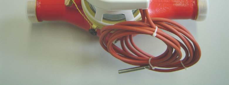
3 2. Technical data Meter size q p 3.5 q p 6 q p 10 Nominal flow rate q p in m³/h Minimum flow rate q i in m³/h (acc. to approval) Accuracy class 2 or 3 acc. to EN 1434 Ratio q i /q p 1:25, 1:50 or 1:100 Maximum flow rate q s in m³/h (short peaks) Temperature measuring C range ( C for wateranrifreezer liquids, uncalibrated) Temperature difference K range Cut-off threshold 0.15 K Admissible temperature C in the flow sensor Flow rate at 0.1 bar ca. 2.5 ca. 3.8 ca. 6.3 pressure loss in m³/h Pressure loss at q p in bar ca ca ca k vs -value ca. 8.1 ca ca (flow rate at 1 bar pressure loss in m³/h) Admissible operating 16 pressure in bar Overall length in mm for horizontal mounting Overall length in mm for riser or down pipe Nominal diameter R 1 DN 25 R 1 DN 25 R 1 ½ DN 40 R 1 ¼ DN 32 Connection thread G 1 ¼ B G 1 ¼ B or or G 2 B G 1 ½ B Length of the connection ca. 1.2 m cable for split instrument Admissible environmental temperature during C operation Storage temperature C Environmental humidity < 93 %, noncondensing (relative air humidity) (dew formation on the outer surface of the flow sensor admissible) Elektromagnetic class E 1 environmental condition Mechanical class M 2 environmental condition Protection class integrator: IP 54 flow sensor: IP 65 Battery lifetime standard version: 6 years + 1 year storage reserve or 10 years (as special version) 3. Installation of the meter PolluCom M can be used as heat and chill meter. For combined heating / chilling plants (automatic switch-over between heat and chill metering) the version PolluCom M H has to be used. Because of the different possibilities of application below terms are used in the following text: Return pipe of heating plants: Supply pipe of heating plants: Return pipe of chilling plants: Supply pipe of chilling plants: Installation in heating plants: colder line warmer line warmer line colder line Usually the flow sensor of PolluCom M is installed in the colder line. For installation points in the warmer line the versions PolluCom MX or PolluCom MX H are available. X implies that the integrator has been adjusted for flow sensors in the warmer line. Installation in chilling plants: It is recommended to install the flow sensor in the warmer line (return pipe) of the chilling plant, because of the reduced dew formation effects. Because of the low temperature difference it is also admissible to use PolluCom M instead of PolluCom MX. In chilling plants and combined heating / chilling plants the integrator is to be removed from the flow sensor and to be mounted separately. The integrator is removed from the flow sensor (pulling it upwards) and mounted separately at a suitable place by means of the delivered wall adapter. The integrator of PolluCom M can be turned through 330 degrees to a perceptible stop. Forced further turning causes the damage of internal components and the loss of warranty entitlement. The flow direction of the heating or cooling liquid is marked by an arrow on the flow sensor. Additional straight inlet or outlet pipes are not required. The flow sensor and the two temperature sensors have to be installed in the same circuit of the heating or cooling plant. It is to be considered that the admissible mounting position of the flow sensor depends on the meter variant: horizontal (integrator shall point upwards) downpipe riser pipe M H 1210 INT, Page 3
4 Before the flow sensor (or at another suitable point in the heating or cooling circuit) a dirt trap is to be installed, as well as a stop cock before and behind the flow sensor in order to be able to dismount the meter after expiry of the verification period without being compelled to empty the pipeline. Before installing the meter rinse the pipeline throroughly, remove the fitting piece (included in the standard mounting kit) or the old meter and then mount the PolluCom M using new gaskets. Examples of installation: Fig. 1: In new installations DN 25 (R 1 ) both temperature sensors have to be installed directly in the heating or cooling liquid supply line 4. Installation of temperature sensors As far as possible a cable conduit or a cable pipe should be used for laying the cables. In order to achieve the most accurate temperature measurement possible, the tip of the temperature sensor is to be positioned in the middle of the pipe diameter. The cables are to be laid keeping a minimum distance of 0.3 m from electromagnetic influences (generators, motors, frequency converters, etc.) as well as from cables carrying > 50 V. 4.1 Direct installation in the heating or cooling liquid wall adapter ball valve For this type of installation for nominal size DN 25 (R 1 ) the Sensus ball valve with order number is provided. This ball valve is also included in the standard mounting kit DN 25 (R 1 ) for PolluCom M. It is also used for shutting off the pipeline, so that the temperature sensor can be dismounted without having to empty the pipeline. 4.2 Installation in well return line Fig. 2: Installation of the temperature sensors in wells for new installations DN 32 (R 1 ¼ ) and DN 40 (R 1 ½ ) as well as existing installations (verification exchange) DN 25 (R 1 ) to DN 40 (R 1 ½ ) supply line well in tee In order to achieve a correct temperature measurement it is required that the well tip is positioned in the middle of the pipe diameter. Before the temperature sensor can be put into the well, the pressing screw has to be put over the sensor cable at first. Then the two delivered metal half-shells, which are held together by an O-ring, are put onto the sensor from below until they click into the circular groove at the upper end of the sensor (see fig. 3). Please take care without fail that the two half-shells are positioned correctly, and that the chamfer points towards the tip of the temperature sensor. Then insert the sensor into the well up to the stop and screw the pressing screw in. wall adapter return line M H 1210 INT, Page 4
5 5. Display options Temperaturfühlerkabel Temperature sensor Druckschraube Pressing screw Halbschalen Half-shells with mit O-ring O-Ring Temperaturfühler Temperature sensor Tauchhülse Well The different display options of PolluCom M are divided up into six menus. Depending on the meter version and the display masking, some of the display items marked with an asterisk (*) can be shielded. If required, the masking can be changed with the help of the service software MiniCom 3 via the meter s optical data interface. In normal condition the display switches on for one second in intervals of 4 seconds and shows the accumulated heat consumption. By a stroke on the red key, the first display item in the user menu (accumulated heat consumption) is activated. The other five menus can be obtained by depressing the red key for 8 seconds. The selection menu L1 to L6 will appear. Fig. 3: Installation of the temperature sensor in well User menu Target day menu * Pressing screw Archive menu * Service menu Control menu for tariff purposes * Parameter menu * Fig. 5: Change of display menu Fig. 4: Mounted and sealed temperature sensor The menus can be selected by short strokes on the red key in the above sequence. As soon as the desired menu is displayed, depress the red key for 2 seconds in order to get to this menu. The single display items in the menus are activated one after the other by short key strokes. If the key is not operated for 4 minutes, the display will automatically return to the normal condition. In all menus received volume pulses are shown by a blinking impeller symbol (left bottom display corner). M H 1210 INT, Page 5
6 5.1 User menu (example) Error message (only in case of error) Accumulated heat and/or chill energy Target day consumption incl. corresponding date * Accumulated volume Segment test Pulse rate of flow sensor Tariff consumption 1 * (if activated) Tariff consumption chill * (if activated) Consumption pulse meter 1 * (optional) Consumption pulse meter 2 * (optional) Instantaneous flowrate * Instantaneous power * 5.2 Target day menu (example) Customer s reference number * Primary M-Bus address (preset in factory to: 0) * Secondary M-Bus address (preset in factory to: serial number) * All display items are marked with an arrow symbol. Display of all stored values on an adjustable annular target day. Target day value for heat and/or chill energy * Target day value for volume * Target day value for tariff 1 (if activated) * Target day value for tariff chill (if activated) * Target day value for pulse meter 1 (optional) * Target day value for pulse meter 2 (optional) * Return to selection menu (depress for 2 seconds) * Temperature in the warmer line * Temperature in the colder line * Temperature difference * 5.3 Archive menu (example) All display items are marked with a calender sheet symbol. Starting from the current date the values of the turns of the past 16 months are displayed (six-digit date in the form of dd.mm.yy below the main display). Moreover the values for the current month can be called to the display, for this purpose the month to be selected is today. M H 1210 INT, Page 6
7 Selection of the desired month by short keystroke, then depress key for 2 seconds * Heat and/or chill energy * Volume * Tariff consumption 1 (if activated) * Tariff consumption chill (if activated) * Consumption pulse meter 1 (optional) * Consumption pulse meter 2 (optional) * Absolute maximum flow rate incl. date (averaged) * Absolute maximum flow rate incl. time (averaged) * Absolute maximum power incl. Date (averaged) * Absolut maximum power incl. time (averaged) * Absolute maximum temperature in the warmer line incl. date * Absolute maximum temperature in the colder line incl. date * Current date * 5.4. Service menu (example) Maximum flow rate in the selected month incl. date (averaged) * Maximum flow rate in the selected month incl. time (averaged) * Maximum power in the selected month incl. date (averaged) * Maximum power in the selected month incl. time (averaged) * Hours of error condition * Return to month selection (depress for 2 seconds) * Each display item is marked with a man symbol. The service menu shows maximum values and settings of the meter. Current time * Next target day * Operating days * Battery voltage * (calculated) Accumulated failure hours* Primary M-Bus address (preset in factory to: 0) * Secondary M-Bus address (preset in factory to: serial number) * Data communication mode (length and structure of M- Bus protocol) * Version of firmware M H 1210 INT, Page 7
8 Check sum High-resolution energy display * High-resolution volume * Return to selection menu (depress for 2 seconds) * 5.5 Control menu for tariff purposes (example) Each display item is marked with the letters CTRL. Here the tariff functions settings can be controlled. Set averaging interval for flow rate and power * Power in current averaging interval * Flow rate in current averaging interval * Set tariff 1 start time (if activated) * Set tariff 1 end time (if activated) * Switch-over temperature for chill metering (if activated) * Switch-over point for negative temperature difference chill metering (if activated) * Correction factor for waterantifreezer mixtures * Return to selection menu (depress for 2 seconds) * 5.6 Parameter menu (example) Each display item is marked with the tool symbol. This menu is protected by password. The password corresponds to the last three digits of the eight-digit serial number on the meter body. At first 000 appears. Then depress the key for ca. 2 seconds, and the left zero starts blinking. By continuously depressing the key the value of the blinking digit can be changed. As soon as the desired value is obtained, release the key. A short keystroke confirms the set value and switches to the next digit. Here repeat the same procedure. As soon as the last digit has been set, the menu will be released. Now the desired items can be selected by short keystrokes. The values can be set analogical to entering the password. Password enquiry * Setting primary M-Bus address * Setting secondary M-Bus address * Setting customer s reference number * Setting averaging interval for flow rate and power * Setting data communication mode (One, All, F length) * Pulse rate of the first external meter (0.25 to 10,000 l/pulse) * Pulse rate of the second external meter (0.25 to 10,000 l/pulse) * Set date * Set time * Set target day * M H 1210 INT, Page 8
9 6. Function test, sealing Reset absolute maxima * Reset failure hours * Reset power failure hours* Return to selection menu (depress for 2 seconds) * Slowly open the stop cocks and check the installation for leaks. For control purposes the current values of flow rate, power as well as supply flow and return flow temperature can be called to the display according to chapter 5.1. In order to protect the meter against tampering, the delivered self-lock seals have to be applied to the following points: unions of the flow sensor installation point of the separately mounted temperature sensor (see also chapter 4). 7. Potential error situations PolluCom M is equipped with an automatic selfchecking function. In case of error the display shows a four-figure error code in the form Err XYZW. For decoding below allocation can be applied: X: Check of temperature sensors Y: Check of the integrator Z: Error statistics W: Failure in flow sensor Extract: Err 1010 Err 2010 Err 4010 Err 8010 Code Decoding Temperature sensors mixed up or temperature in the colder line exceeds temperature in the warmer line One or both temperature sensors is/are short-circuited Cable failure of temperature sensor for colder line Cable failure of temperature sensor for warmer line In most cases the error situation Err 1010 is caused by temporary plant conditions, as soon as the temperature in the warmer line drops by at least 3 K below the temperature in the colder line. In case of all other error situations please contact our Customer Service. 8. Optical interface and optional modules 8.1 Optical interface All meters are equipped with an optical data interface. Via an optical data coupler (e.g. order number for RS 232 connection or order number for USB connection) set parameters can be changed with the use of the service software MiniCom 3, or the meter can be read out via the readout system DOKOM Mobil. The data interface is activated for an hour by a short keystroke. By every meantime data communication this period of time starts again, so that e.g. a logger readout in 15-minute or hourly intervals is possible during a longer time. 8.2 M-Bus option acc. to EN This option allows a readout of the meter via its primary or secondary address by means of an M- Bus level converter (300 and 2400 Baud, automatic recognition). Both addresses can be set in the parameter menu (see chapter 5.6) or with the help of the service software MiniCom 3 (Please note: The secondary address preset in the factory corresponds to the serial number on the meter body). The primary address can be set between 0 and 250 and has been preset in the factory to 0. The optional two-wire cable is integrated in the M- Bus system at a suitable place. The polarity of the two wires can be disregarded. M H 1210 INT, Page 9
10 8.3 Mini-Bus option This option allows the meter to be connected with an inductive readout point (MiniPad, order number ). The total length of the two-wire cable between meter and readout point must not exceed 50 meters. The polarity of the two wires can be disregarded. The transferred protocol corresponds to the M-Bus protocol, and the meter can be read out via the MiniReader (order no ) or with the help of the readout system DOKOM Mobil. 8.4 Remote reading option for heat consumption pulses The four-wire cable is connected as follows: White = external meter 1 / positive pole Brown = external meter 1 / negative pole Green = external meter 2 / positive pole Yellow = external meter 2 / negative pole Specification of contact inputs: Required closing time: Input frequency: Terminal voltage: > 125 ms < 3 Hz 3 V The required programming regarding: Pulse rate: Closing time: Bounce time: Max. voltage: Max. current: 10 kwh 125 ms none 28 V DC or AC 0.1 A meter type physical unit and rate of input pulse initial meter reading The two-wire cable is connected to a suitable pulse totalizer or to the contact input of a house control system. The polarity of the two wires can be disregarded. 8.5 M-Bus option / Mini-Bus option with two contact inputs In addition to the module specified in chapter 8.2 or 8.3 two external consumption meters (cold water, warm water, electricity, gas, others) with passive remote reading contact (Reed switch or open collector) can be connected. This option has altogether two connection cables ( 1 x two wires, 1 x four wires). The two-wire cable (white and brown wire) is integrated at a suitable place in the M-Bus or Mini-Bus system, the polarity can be disregarded. meter number and M-Bus addresses is carried out via service software MiniCom Optional integrated data logger The integrated data logger stores consumption values and instantaneous values (power, flow rate, temperatures) in a selectable time interval (3 to 1440 minutes). The logger data can be read out via the optical interface, M-Bus or Mini-Bus with the help of the service software MiniCom 3. The time interval (preset in the factory to 60 minutes) can also be changed with the help of MiniCom 3. M H 1210 INT, Page 10


11 Annex: EC conformity declaration M H 1210 INT, Page 11
 621 6904-0 Fax: + 49 (0) 621 6904-1409 E-mail: info.de@sensus.")
12 Material number: Edition: October 2007 Subject to changes Sensus Metering Systems GmbH Industriestraße 16 D Ludwigshafen Phone: + 49 (0) Fax: + 49 (0) info.de@sensus.com M H 1210 INT, Page 12
Heating / Cooling Meter PolluCom E Installation and Operation Instructions
 Our compact meter PolluCom E is used for measuring energy consumption in plants carrying water as heating or cooling liquid. These installation and operation instructions specify how to install and operate
Ultrasonic heat meter
 Ultrasonic heat meter Installation and user guide Flow sensor-vmc-p Energy integrator Compact heat meter Temperature senor CONTENTS Kapitel Please read this manual prior to installation Page 3 2! T! Important
SensoStar C. Installation and Operating Instructions Heat Meter Calculator Heat/Cooling Meter Calculator Cooling Meter Calculator
 Installation and Operating Instructions Heat Meter Calculator Heat/Cooling Meter Calculator Cooling Meter Calculator SensoStar C DE-18-MI004-PTB037 (MID heat) DE-18-M-PTB-0049 (national German cooling)
SonoMeter 30 Energy Meters
 SonoMeter 30 Energy Meters Description MID examination certificate no.: LT-1621-MI004-020 The Danfoss SonoMeter 30 is a range of ultrasonic, compact energy meters intended for measuring energy consumption
SonoMeter 30 Energy Meters
 SonoMeter 30 Energy Meters Description The Danfoss SonoMeter 30 is a range of ultrasonic, compact energy meters intended for measuring energy consumption in heating and cooling applications for billing
zelsius Installation and operating manual All that counts. EnergyMetering
 EnergyMetering zelsius Installation and operating manual Electronic compact heat meter with single jet flow sensor M-Bus and 2 inputs/outputs optional qp 0.6/1.5/2.5 m³/h All that counts. General information
Compact Heat Meters. Features. -A Pulsed output. -B M-Bus output. Accessories. UK Sales Tel: International Tel:
 Compact Heat Meters Features Compact design Simple operation Pulsed output Measures heating or cooling Specification Product Codes Water Meter Temp. range 10 to 90 C Nominal pressure 16bar Installation
IFX-M4-03 IFX-M4-03_D_E_2017_05_REV.0
 IFX-M4-03 IFX-M4-03_D_E_2017_05_REV.0 Table of contents PRINCIPLE... 4 HOW TO ORDER... 4 TECHNICAL DATA... 5 Table 1.1... 6 Table 1.2... 7 Table 1.3... 7 Straight pipelines lengths... 7 Conveying liquid...
zelsius Installation and operating manual All that counts EnergyMetering
 EnergyMetering zelsius Installation and operating manual Electronic compact heat meter M-Bus and 2 inputs/outputs optional Coaxial measuring capsule 2" q p 0.6/1.5/2.5 m³/h All that counts General information
Datasheet PDCSY-MW-CHM. Technical Overview. Features. Product warranty and total quality commitment. General Information.
 Datasheet Compact Heat Meters Technical Overview Heat energy is calculated by using a matched pair of high accuracy sensors to measure the difference between the forward and flow temperatures. The amount
SHARKY 775 COMPACT ENERGY METER ULTRASONIC
 APPLICATION The ultrasonic compact energy meter can be used for measuring the energy consumption in heating / cooling application for billing purposes. FEATURES 4 Approval for ultrasonic meter with dynamic
CORONA E ELECTRONIC METER MULTI-JET
 APPLICATION Fully electronic compact water meter with impeller scanning for recording volume. Highly accurate recording of all billing data at medium temperatures up to 90 C. FEATURES 4 Electronic sensor
Superstatic 749. Fluidic Oscillation Compact Heat Meter
 Superstatic 749 Fluidic Oscillation Compact Heat Meter Application The Superstatic 749 is an autonomous compact thermal energy meter consisting of a flow meter an integrator and a pair of temperature sensors.
Fluidic Oscillation Compact Heat Meter of High-Tech Composite
 Superstatic 789 Fluidic Oscillation Compact Heat Meter of High-Tech Composite Application The Superstatic 789 is an autonomous compact thermal energy meter consisting of a high-tech composite flow meter
EW130 Series Multijet Water Meters DN15 40 FOR COLD AND WARM POTABLE WATER APPLICATIONS
 EW10 Series Multijet Water Meters DN15 0 FOR COLD AND WARM POTABLE WATER APPLICATIONS CONTENTS PRODUCT DATA Fig. 1. EW100BM / EW101BM Contents... 1 General... 2 Application... 2 Features... 2 Design...
WSTH/WPTH. Woltmann type combined energy meter. Measuring distance. Function. Connection. High reliability. Mounting.
 Woltmann type combined energy meter Flanged Woltmann flow meters for large nominal flows, intended for flow measurements in large plants, such as those found in district heating systems. Size DN50 DN300
Instruction of connection and programming of the VECTOR controller
 Instruction of connection and programming of the VECTOR controller 1. Connection of wiring 1.1.VECTOR Connection diagram Fig. 1 VECTOR Diagram of connection to the vehicle wiring. 1.2.Connection of wiring
Supercal 539. Compact thermal energy meter
 Supercal 539 Compact thermal energy meter Application Electronic, battery-powered compact thermal energy meter intended to record heat consumption in autonomous heating systems or combined heating/cooling
US-S/FFL. Ultrasonic energy meters. Function. Flexible design. Connection. Mounting. High reliability
 Revision 2017-08-15 Ultrasonic energy meters Flanged ultrasonic energy meters, intended for heating or cooling. Size DN25 DN100 Nominal flow 3.5 60 m³/h For horizontal or vertical mounting No data loss
EW447-EW452 Series Mechanical Heat Meters FOR HEATING AND COOLING APPLICATIONS
 EW447-EW452 Series Mechanical Heat Meters FOR HEATING AND COOLING APPLICATIONS Application PRODUCT DATA Static compact heat meter with electronic measurement, consisting of electronic energy integrator
ULTRASONIC FLOW SENSOR QALCOSONIC FLOW 2
 AB AXIS INDUSTRIES ULTRASONIC FLOW SENSOR QALCOSONIC FLOW 2 TECHNICAL DESCRIPTION, INSTALLATION AND USER INSTRUCTIONS PESF2V01 KAUNAS Contents Page SAFETY INFORMATION... 1. APPLICATION FIELD... 2. TECHNICAL
SITRANS FUE950 *085R9430* Energy calculator type SITRANS FUE950. Operating Manual Edition 09/ Revision 03
 s Operating Manual Edition 09/2006 - Revision 03 SITRANS FUE950 Energy calculator type SITRANS FUE950 District heating application Chilled water application Combined cooling/heating application [ ] Order
BAYLAN AUTOMATED TEST BENCH
 BAYLAN AUTOMATED TEST BENCH At this test bench, the electromagnetic flow meters are used with the measurement method. Calibrations of flowmeters are made with the help of the water collection tank and
RAY COMPACT ENERGY METER MECHANICAL
 APPLICATION Fully electronic compact heat meter or compact cooling and heat meter with impeller scanning for recording energy and volume data. Highly accurate recording of all billing data in a heating
Fluidic Oscillation Compact Heat Meter
 Fluidic Oscillation Compact Heat Meter Application The Superstatic 749 is an autonomous compact thermal energy meter consisting of a flow meter a detachable integrator with a wide range of communications
Octave Water Meter Installation Manual
 Octave Water Meter Installation Manual 1.0 Notes For proper flow measurements, the OCTAVE s measuring tube should be completely full at all times. Non-wetted sensors show loss of signal. Though this will
Series 7000 Torque Sensor for PTO-shafts
 Properties PTO (Power Take-Off) shaft with integrated torque and angle measurement Non-contact measurement system, high robustness Special for PTO shafts 1 ¾ und 1 3/8 Plug & Play solution, no additional
HYDRUS ULTRASONIC METER
 APPLICATION Static ultrasonic water meter for accurate measuring and recording for all applications of water supply. FEATURES 4 Real data communication, open metering telegram 4 Long-term stability under
ULTRASONIC FLOW SENSOR IFX-M4-01
 ULTRASONIC FLOW SENSOR IFX-M4-01 TECHNICAL DESCRIPTION, OPERATING INSTRUCTION IFX-M4-01 2012-09-10 TABLE OF CONTENTS 1. APPLICATION... 3 2. TECHNICAL DATA... 4 3. PACKAGE CONTENT... 6 4. OPERATING PRINCIPLE...
Heat Meter Integrator
 Heat Meter Integrator Features Simply operation Integral wall and DIN-rail mounting bracket Pulsed or M-Bus output options Measures heating or cooling and heat/cooling Specification Product Codes Temperature
Electronic Water Meters in measuring cell design
 5 343 SIEMECA Electronic Water Meters in measuring cell design WMC... WMH... Electronic, mains-independent meters to acquire water consumption in autonomous domestic water plants. Storage and display of
c-go 24V/6A 24V/8A 24V/12A
 c-go 24V/6A 24V/8A 24V/12A Battery charger GB Instruction manual 1 Index 1. Product description... 2 2. Safety advices... 3 3. Quick start guide... 4 4. Operation... 4 5. Problem solving... 6 6. Specifications...
Series 7000 Torque Sensor for PTO-shafts
 Properties PTO (Power Take-Off) shaft with integrated torque and angle measurement Non-contact measurement system, high robustness Special for PTO shafts 1 ¾ und 1 3/8 Plug & Play solution, no additional
Superstatic 440. Static Heat Meter, Static Cooling Meter. Application
 Superstatic 440 Static Heat Meter, Static Cooling Meter Application Design The Superstatic 440 is a static heat or cooling meter according to standard EN1434 class 2 based on the fluid oscillation principle,
Ulyser Component Maintenance Manual
 No. MA_Ulyser_CMM_E_Rev_1.2 Ulyser Component Maintenance Manual Novega Produktionssysteme GmbH Gewerbepark 2 87477 Sulzberg (See) Germany Fon: +49/8376/92990-0 Fax: +49/8376/92990-20 info@novega.de www.novega.de
WZMC-402 Ultrasonic Apartment Energy Meters
 Product sheet MT8.36 Meter Type WZMC-402 WZMC-402 Ultrasonic Apartment Energy Meters WZMC-402 is used for metering heat in small and medium-sized central heating plants and district heating plants, typically
M-bus impeller type heat and heat/refrigeration meters
 Metering M-bus impeller type heat and heat/refrigeration meters WF..5.. Electronic, mains-independent impeller type meters with optional refrigeration range to acquire heat or cooling energy consumption
Electronic Water Meters
 5 341 Electronic Water Meters WFC... WFH... Electronic, mains-independent meters to acquire water consumption in autonomous domestic water plants. Storage and display of the cumulated consumption values
User Guide. Lubricus Lubrication System LUB-D1/LUB-D2/LUB-D3/LUB-D4 (24 VDC)
") User Guide Lubricus Lubrication System LUB-D1/LUB-D2/LUB-D3/LUB-D4 (24 VDC) version 04/2013 Content General Information 3 Warning 3 Scope of Supply 3 Overview 3 General safety details 4 Intended use 4
User Guide Lubricus Lubrication System LUB-D1/LUB-D2/LUB-D3/LUB-D4 (24 VDC) version 04/2013 Content General Information 3 Warning 3 Scope of Supply 3 Overview 3 General safety details 4 Intended use 4
Compact Static Heat Meter of High-Tech Composite
 Compact Static Heat Meter of High-Tech Composite Application The Superstatic 789 is a lightweight and robust compact heat meter consisting of a high-tech composite flow meter, a detachable integrator with
Datasheet PDCSY-MW-U. Technical Overview. Features. Product warranty and total quality commitment.
 Datasheet Ultrasonic Flow Sensors & Integrator Technical Overview Ultrasonic flow sensors have no moving parts in the volume flow, this makes them almost wear free and noiseless. They measure the flow
MagFlux Q 8200 Series
 MagFlux Q 8200 Series 3.06 ELECTROMAGNETIC FLOW METER General MagFlux Q Electromagnetic Flow Meter, created in composite materials, designed with an optimized construction which secures optimal performance.
Quick Guide. brite Advanced Retail scale
 Quick Guide brite Advanced Retail scale 2 METTLER TOLEDO Quick Guide brite Advanced Contents 1 Your new retail scale...4 1.1 Safety instructions...4 1.2 Further documents...4 1.3 Maintenance...4 1.4 Intended
Screw-type and measuring capsule heat meter with IrDA interface and an interface for retrofitting external modules or with integrated communication.
 Data sheet DST2-QHEA-GB0 HMx / 11.05.2016 - V 1.0 Heat meter Q heat 5 Screw-type and measuring capsule heat meter with IrDA interface and an interface for retrofitting external modules or with integrated
Superstatic 440. Static Heat- and Cooling Meter. Application
 Superstatic 440 Static Heat- and Cooling Meter Application Design The Superstatic 440 is a static heat- and cooling meter according to standard EN1434 class 2 based on the fluid oscillation principle,
HYDROMETER. Operating Instructions Edition 03/ Revision 05. Ultrasonic flowmeter type SHARKY 475 [ ] A5E HYDRO.PS.022.Q5.
![HYDROMETER. Operating Instructions Edition 03/ Revision 05. Ultrasonic flowmeter type SHARKY 475 [ ] A5E HYDRO.PS.022.Q5.](/thumbs/89/100174146.jpg "HYDROMETER. Operating Instructions Edition 03/ Revision 05. Ultrasonic flowmeter type SHARKY 475 [ ] A5E HYDRO.PS.022.Q5.") HYDROMETER Operating Instructions Edition 03/2008 - Revision 05 Ultrasonic flowmeter type SHARKY 475 [ ] A5E02144773 HYDRO.PS.022.Q5.02 Introduction 1 General safety instructions 2 Description 3 Installation
HYDROMETER Operating Instructions Edition 03/2008 - Revision 05 Ultrasonic flowmeter type SHARKY 475 [ ] A5E02144773 HYDRO.PS.022.Q5.02 Introduction 1 General safety instructions 2 Description 3 Installation
ECONOMISER SERIES E2T USER MANUAL
 TURBO S.R.L. Electronic Control Systems for Dust Collectors e-mail: info@turbocontrols.it web: www.turbocontrols.it TEL. ++39 (0)362 574024 FAX ++39 (0)362 574092 ECONOMISER SERIES E2T USER MANUAL 24/06/2014
Electronic Heat Meters
 5 333 WFQ2... WFM2... MEGATRON2 Electronic Heat Meters WFM2... WFQ2... Electronic, mains-independent meters to acquire heating energy consumption in autonomous heating and domestic hot water plants. Storage
TOPAS PMW-basic. Customer benefits. Product features
 TOPAS PMW-basic The TOPAS PMW-basic product line covers a wide range of applications in hot water measurement. This innovative system offers all types of water measurement right up to data integration
WATERFLUX 3070 Quick Start
 WATERFLUX 3070 Quick Start Battery powered electromagnetic water meter Electronic Revision ER 4.3.0_ up to ER 4.3.4_ (SW.REV 4.2.2_ up to 4.2.5_) KROHNE CONTENTS WATERFLUX 3070 1 Safety instructions 4
aquaconcept Product features Customer benefits
 aquaconcept The unique aquaconcept modular design covers a wide range of water applications. This innovative system offers all types of water measurement right up to data integration into your specific
RAY MECHANICAL COMPACT METER. 4 MID approved class 2 from DN 15mm qp 0,6m3/h up to DN 40mm qp 10m3/h
 APPLICATION is a fully electronic multi-jets compact heat meter or compact heat and cooling meter with impeller scanning for recording energy and volume data. is equipped with 2 temperature sensors. is
Liquid Turbine Flow Meter OwnerÊs Manual
 Liquid Turbine Flow Meter OwnerÊs Manual Manual LWGY-G Rev.1.0 Content 1.0 GENERAL INFORMATION... 1 2.0 SPECIFICATIONS... 2 3.0 OPERATION CONDITIONS... 3 4.0 CAUTIONS FOR INSTALLATION... 4 5.0 DIMENSION...
Operating Instructions. Angle Seat Control Valve. Type 7020
 Operating Instructions Angle Seat Control Valve Type 7020 With: Digital Positioner Type 8048 Electro-pneumatic Positioner Type 8047 Pneumatic Positioner Type 8047 Version: 02/2006 Manual-7020e.doc Art.-No:
SPG-DIGI. Operating Instruction. Please read carefully before use!
 WALTER STAUFFENBERG GMBH & CO.KG Im Ehrenfeld 4 D-58791 Werdohl Postfach 1745 D-58777 Werdohl Germany Tel.: +49 (0) 2392 / 916-0 Fax: +49 (0) 2392 / 2505 E-Mail: sales@stauff.com Internet: www.stauff.com
Operating Instructions
 Operating Instructions ASI Control Head for Lift and Turning Valves Subject to technical modifications and innovations. Rev. 4 ASI Steuerkopf für Hub- und Drehventile Beschreibung 100xxx / Doku / Elek
SPREADER SYSTEM. Proportional three function. 1. Features and Specifications. User Manual 12 INPUTS 12 OUTPUTS CONNECTIVITY MAIN FEATURES
 User Manual SPREADER SYSTEM Proportional three function 12 INPUTS 3 interrupt digital inputs. 3 digital inputs for engine control (alternator, accelerator, oil alarm). 1 digital input for tachometer (squared,
CORONA ER ELECTRONIC METER MULTI-JET
 APPLICATION Fully electronic compact water meter with impeller scanning for recording volume. Highly accurate recording of all billing data at medium temperatures up to 90 C. FEATURES 4 Inbuilt radio module
SonoSelect and SonoSafe energy meters
 energy meters 03/2017 Danfoss VUIGB602 www.heating.danfoss.com 1 Note! To ensure latest version of declaration, please visit danfoss.com. 2 Danfoss Energy Meters 2017.03 VUIGB702 Contents 1. Inside the
Arm - TX series 40 family
 Arm - TX series 40 family Characteristics Stäubli Faverges 2005 D18327304A - 02/2005 The specifications contained in the present document can be modified without notice. Although all necessary precautions
EG DYNAMIC user manual
 Timing Advance Processor EG DYNAMIC user manual ver. 1.1.0 dated 2012-10-01 This instruction can be also downloaded from: http://www.europegas.pl/en/technical-support/service-manuals Latest software version
F 90 Heat Meter Warmly recommended to cool-headed economisers
 F 90 Heat Meter Warmly recommended to cool-headed economisers Available in three types for a multitude of job profiles. PICOTHERM 2e the economy heat meter without data outputs. PICOTHERM 2 the compact-size
Inline Flow meter for compressed air and gases DN15 (1/2 ) - DN80 (3 )
 - DN80 (3 )") EE771/EE772 Inline Flow meter for compressed air and gases DN15 (1/2 ) - DN80 (3 ) The inline flow meter EE771/EE772, based on the measurement principle of thermal mass flow, is ideally suited for the
EE771/EE772 Inline Flow meter for compressed air and gases DN15 (1/2 ) - DN80 (3 ) The inline flow meter EE771/EE772, based on the measurement principle of thermal mass flow, is ideally suited for the
Operating Instructions
 Operating Instructions ASI Control Head for Lift and Turning Valves Subject to technical modifications and innovations. Rev. 6 ASI Steuerkopf für Hub- und Drehventile Beschreibung 100xxx / Doku / Elek
Model TUR-200D Turbine Flowmeter
 General Specifications Model TUR-200D Turbine Flowmeter Liquid flows through the turbine housing causing an internal rotor to spin. As the rotor spins, an electrical signal is generated in the pickup coil.
WESAN WPV E ELECTRONIC METER WOLTMAN
 APPLICATION Meter for measuring heavily fluctuating flow rates. FEATURES 4 Calibratable and exchangeable measuring insert in one unit, suitable for calibration comprising: measuring insert as main meter,
OPERATIONS MANUAL CR Thermoreactor
 OPERATIONS MANUAL CR 2200 Thermoreactor CR 2200 Note For the most recent version of the manual, please visit www.ysi.com. Contact Copyright YSI 1725 Brannum Lane Yellow Springs, OH 45387 USA Tel: +1 937-767-7241
SonoSelect and SonoSafe energy meters
 energy meters 01/2016 Danfoss VUIGB202 1 2 Danfoss Energy Meters 2016.01 VUIGB202 Contents 1. Inside the box... 4 2. Installation..............................................................................
Infocal 9 Energy calculator for heating and cooling applications
 Installation Guide Infocal 9 Energy calculator for heating and cooling applications www.danfoss.com 2 Danfoss Energy Meters 2018.08 VU.IG.N2.02 1. Installation 1.1. Preparation Only qualified personnel
Measuring capsule heat meter G54 / G55
 Measuring capsule heat meter G54 / G55 Measuring capsule heat meter with optical interface and external modules for retrofitting. Thanks to integrated modules, the devices can be equipped with the required
Instruction Manual. Coating Thickness Gauge. Optionally with Memory
 Instruction Manual Coating Thickness Gauge 1500 Optionally with Memory 1 Introduction The QNix 1500 is a part of the product line of non-destructive coating thickness measurement gauges manufactured by
WATER METERS OCTAVE ULTRASONIC WATER METER INSTALLATION & USER GUIDE
 WATER METERS OCTAVE ULTRASONIC WATER METER INSTALLATION & USER GUIDE OCTAVE ULTRASONIC WATER METER INSTALLATION & USER GUIDE TABLE OF CONTENTS General Information...4 Warranty...4 Included Items...4 Operation...5
Hello, I am the new Zelsius C5 heat meter. The new generation of ultrasonic heat and cooling meters for precise energy consumption measurement.
 Hello, I am the new Zelsius C5 heat meter The new generation of ultrasonic heat and cooling meters for precise energy consumption measurement. zelsius C5 Ultrasonic Energy Meter About The ZENNER C5 Ultrasonic
Axial Turbine Flow Sensor Series Turbotron VTH 25 / VTI 25 / VTM 25
 Installation Instruction Axial Turbine Flow Sensor Series Turbotron VTH 25 / VTI 25 / VTM 25 Table of contents Page 1 Function of Turbotron 1 2 Safety instructions 2 3 Important notes and requirements
MULTICHANNEL ULTRASONIC FLOW METER AFLOWT UF
 MULTICHANNEL ULTRASONIC FLOW METER AFLOWT UF VERSION UF-5xx d INSTALLATION MANUAL ISO 9001:2008 CONTENTS Page INTRODUCTION... 3 1. SAFETY INSTRUCTIONS... 4 2. MOUNTING PREPARATION... 4 3. MOUNTING REQUIREMENTS...
Installation & Maintenance Instructions MULTICAL 403. Supplied by. .com. Call us on +44 (0)
") Installation & Maintenance Instructions MULTICAL 403 Supplied by.com Call us on +44 (0)118 916 9420 Email info@ Installation and user s guide MULTICAL 403 1 Information Permissible operating conditions
Installation & Maintenance Instructions MULTICAL 403 Supplied by.com Call us on +44 (0)118 916 9420 Email info@ Installation and user s guide MULTICAL 403 1 Information Permissible operating conditions
Data sheet MULTICAL 6L2. Data loggers Info loggers Data backup in case of power failure MID-2004/22/EC EN 1434
 Data sheet MULTICAL 6L2 Data loggers Info loggers Data backup in case of power failure MID-2004/22/EC EN 1434 M15 0200 Contents Calculator functions 3 Cabinet design 7 Approved meter data 8 Electrical
Operating Instructions. bluesmart Active
 Table of contents 1. Overview 3 2. Safety 3 2.1 Symbols in these instructions 3 2.2 Intended use 4 2.3 Responsibility of the operator 4 3. Setup and function 4 3.1 Brief description 4 3.2 Overview 5 3.3
BERMAD Waterworks. Insertion Flow Meter Device (IFM)
") IFM-MUT1222PRV BERMAD's IFM-MUT1222-PRV SENSOR is designed for measuring the flow rate of valves sized DN80 to DN600 (3-24 ). This document describes the installation process of the sensor. For larger
IFM-MUT1222PRV BERMAD's IFM-MUT1222-PRV SENSOR is designed for measuring the flow rate of valves sized DN80 to DN600 (3-24 ). This document describes the installation process of the sensor. For larger
HGM1780. Automatic Genset Controller USER MANUAL. Smartgen Technology
 HGM1780 Automatic Genset Controller USER MANUAL Smartgen Technology Smartgen Technology Co., Ltd No. 28 Jinsuo Road Zhengzhou Henan Province P. R. China Tel: 0086-371-67988888/67981888 0086-371-67991553/67992951
Flow VA 500/ 520. Flow sensors for compressed air and gases incl. temperature measurement. Verbrauch.
 VA 500/ 520 Flow sensors for compressed air and gases incl. temperature Verbrauch 79 What are the advantages of the flow measuring technology of CS Instruments? 1) Even under pressure, the ow sensor VA
Operating Instructions. Pneumatic Control Valve Low Temperature. Type Series GS3
 Operating Instructions Pneumatic Control Valve Low Temperature Type 8026 Series GS3 With: Digital Positioner Type 8048 Electro-pneumatic Positioner Type 8047 Pneumatic Positioner Type 8047 Version: 03/2006
Flow VA 550 / 570. DVGW tested. Flow.
 VA 550 / 570 DVGW tested Flow www.cs-instruments.com 67 VA 550 compressed air and gases Application range: Ideal also for the outdoor area Compressed air measurement and distribution Leakage measurement
Type Operating Instructions. Bedienungsanleitung Manuel d utilisation. 2/2-Way Solenoid Valve 2/2-Wege-Magnetventil Électrovanne à 2/2 voies
 Type 5282 2/2-Way Solenoid Valve 2/2-Wege-Magnetventil Électrovanne à 2/2 voies Operating Instructions Bedienungsanleitung Manuel d utilisation 1 OPERATING INSTRUCTIONS The operating instructions contain
TomTom-Tools GmbH Wiesenstrasse Baden Switzerland. Phone 1: Phone 2: VAT ID:
 TomTom-Tools GmbH Wiesenstrasse 15 5400 Baden Switzerland www.tomtom-tools.com Phone 1: +41 79 774 06 42 Phone 2: +41 79 774 06 44 VAT ID: 698 468 Info@tomtom-tools.com User Manual: (Draft Version) OVALITY
F-4600 INLINE ULTRASONIC FLOW METER Installation and Operation Guide
 F-4600 INLINE ULTRASONIC FLOW METER Installation and Operation Guide 11451 Belcher Road South, Largo, FL 33773 USA Tel +1 (727) 447-6140 Fax +1 (727) 442-5699 1054-7 / 34405 www.onicon.com sales@onicon.com
ThunderION. Static Neutralising System. GB User's Manual 2
 ThunderION SIMCO (Nederland) B.V. Postbus 71 NL-7240 AB Lochem Telefoon +31-(0)573-288333 Telefax +31-(0)573-257319 E-mail general@simco-ion.nl Internet http://www.simco-ion.nl Traderegister Apeldoorn
REQUIRED TOOLS 3 mm screw driver Wrench Crosstip screwdriver
 MOUNTING AND OPERATING INSTRUCTIONS CF Echo II DELIVERY CF ECHO II Compact heat meter with removable calculator 1 connected fl ow meter 2 temperature sensors (optional) 1 wall mounting bracket 1 package
RS-110 Rainfall Sensor Installation Guide
 RS-110 Rainfall Sensor Installation Guide for XR440 and XR5 Data Loggers September 2015 Revision 1.1 1 Disclaimer The following warranty and liability disclaimer apply to this product. PACE SCIENTIFIC
MULTICAL 6M2. Data sheet
 Data sheet MULTICAL 6M2 Tailored for mixed fluids Data loggers Info loggers Data backup in case of power failure Measurement at subzero temperatures Configurable fluid type and concentration level Contents
HD [ GB ] Tipping bucket rain gauge
![HD [ GB ] Tipping bucket rain gauge](/thumbs/81/82695156.jpg "HD [ GB ] Tipping bucket rain gauge") HD 2015 [ GB ] Tipping bucket rain gauge [ GB ] [ GB ] Description The HD2015 is a reliable and sturdy bucket rain gauge, entirely constructed of corrosion resistant materials in order to guarantee its
HD 2015 [ GB ] Tipping bucket rain gauge [ GB ] [ GB ] Description The HD2015 is a reliable and sturdy bucket rain gauge, entirely constructed of corrosion resistant materials in order to guarantee its
The RCS-6V kit. Page of Contents. 1. This Book 1.1. Warning & safety What can I do with the RCS-kit? Tips 3
 The RCS-6V kit Page of Contents Page 1. This Book 1.1. Warning & safety 3 1.2. What can I do with the RCS-kit? 3 1.3. Tips 3 2. The principle of the system 2.1. How the load measurement system works 5
Model 7400 OPERATOR MANUAL
 Model 7400 OPERATOR MANUAL DORAN SCALES, INC. 1315 PARAMOUNT PKWY. BATAVIA, IL 60510 1-800-262-6844 FAX: (630) 879-0073 http://www.doranscales.com MANUAL REVISION: 1.0 MAN0198 10/3/2005 INTRODUCTION Introducing
Type 3360, Service Manual. Serviceanleitung Service Manuel
 Electromotive control valve Elektromotorisches Regelventil Vanne de régulation électromotorisée Service Manual Serviceanleitung Service Manuel We reserve the right to make technical changes without notice.
Important instructions
 Operation manual Please read this manual, before starting the unit. It contains important notes on commissioning and handling. Keep these instructions for future reference. Be careful even if you pass
l The Battery Tester is designed for measuring the l AC four-terminal method to measure the internal
 Certificate of Calibration We hereby certify that this product has been calibrated and found to be in accordance with the applicable SPECIFICATIONS and STANDARDS. Accuracies of the standard equipment used
ATOTH-G Series BLDC Motor Controller. User s Manual
 ATOTH-G Series BLDC Motor Controller User s Manual Contents Chapter One Summary...1 Chapter Two Main Features and Specifications.2 2.1 Basic Functions...2 2.2 Features... 5 2.3 Specifications...6 Chapter
Electronic Limit Switch Type
 Electronic Limit Switch Type 3738-20 with optional solenoid valve for on/off rotary actuators Application Electronic limit switch for on/off applications to indicate the end position of rotary actuators.
DL 01. Battery Powered Precision Digital Gauge for Leak Testing. Stainless Steel Sensor. class 0.05
 DL 0 Battery Powered for Leak Testing Stainless Steel Sensor class 0.05 Nominal pressure from 0 00 mbar up to 0... 00 bar Special characteristics modular sensor concept data logger graphic display stainless
Mounting and Operating Instructions EB 8222 EN. Type 3310/AT and Type 3310/3278 Pneumatic Control Valves. Type 3310 Segmented Ball Valve
 Type 3310/AT and Type 3310/3278 Pneumatic Control Valves Type 3310 Segmented Ball Valve Fig. 1 Type 3310/3278 with positioner Fig. 2 Type 3310/AT Mounting and Operating Instructions EB 8222 EN Edition