Control Panel. Operation and Service Manual
|
|
|
- Claude Ferguson
- 6 years ago
- Views:
Transcription


1 Control Panel Operation and Service Manual 1
2 2

3 Important Note Before applying power to the control panel, all wiring to the panel should be per NEC. Specifically check for proper voltage and that the neutral is grounded at the source. An equipment ground should also be run to the panel. *See Wiring Instructions and Diagrams before proceeding. Before start-up you need to enter all system values and options. See section on Setpoint Values. 3
4 4
5 Table of Contents Important Note... 3 Standard Vilter Warranty... 7 Operational Flow Charts... 9 Installation Recommendations Best Practices Vission 20/20 Architecture Digital Input/Output Analog Inputs Analog Outputs Touch Screen LCD Display Menu Screen Compressor Control Screen Pump-Down and Pull-Down Setpoints Additional Control Setpoints Alarms and Trips Screen Alarms and Trips Timers Timers Service Options Instrument Calibration Slide Calibration Command Shaft Rotation Slide Valve Operation Slide Valve Trouble Shooting Guide Trend Chart Event List Screen Input / Output States Configuration Screens Maintenance Screen Log In Screen Screen to Add Users User Security Levels Safety Failure Message Vission 20/20 Troubleshooting Guide
6 Digital & Analog Boards Digital Output # Digital Output # Digital Input Digital Input/Output # Digital Input/Output # Analog Input # Analog Input # Analog Input # Analog Input # Analog Output Optional Analog Input Jumper Tables
7 Standard Vilter Warranty Seller warrants the products it manufactures to be free from defects in material and workmanship for a period of eighteen (18) months from the date of shipment from Seller s manufacturing plant or twelve (12) months from date of installation at the initial end users location, whichever occurs first. In addition, Seller provides the following extended warranties: (a) three (3) years from the date of shipment on single screw compressor internal rotating parts, (b) two (2) years from the date of shipment on reciprocating compressors and single screw and reciprocating compressor parts, and (c) two (2) years on all other parts on a single screw compressor unit. Such warranties do not apply to ordinary wear and tear. Seller does not warrant that the product complies with any particular law or regulation not explicitly set forth in the specifications, and Buyer is responsible for ensuring that the product contains all features necessary to safely perform in Buyer s and its customer s plants and operations. Buyer must notify Seller of any warranty claim within ten (10) days after such claim arises, otherwise Buyer waives all rights to such claim. Products supplied by Seller, which are manufactured by others, are not warranted by Seller, but rather Seller merely passes through the manufacturer s warranty to Buyer. SELLER EXPRESSLY DISCLAIMS ALL OTHER WARRANTIES, WHETHER EXPRESS OR IMPLIED, INCLUDING THE IMPLIED WARRANTIES OF MERCHANTABILITY AND FITNESS FOR A PARTICULAR PURPOSE. Unless otherwise agreed in writing, Buyer s sole remedy for breach of warranty is, at Seller s option, the repair of the defect, the correction of the service, or the providing a replacement part FOB Seller s office. Seller will not be responsible for costs of dismantling, lost refrigerant, reassembling, or transporting the product. Further, Seller will not be liable for any other direct, indirect, consequential, incidental, or special damages arising out of a breach of warranty. THESE WARRANTY REMEDIES ARE EXCLUSIVE AND ALL OTHER WAR- RANTY REMEDIES ARE EXCLUDED. Products or parts for which a warranty claim is made are to be returned transportation prepaid to Seller s factory. Any improper use, corrosion, neglect, accident, operation beyond rated capacity, substitution of parts not approved by Seller, or any alteration or repair by others which, in Seller s judgement, adversely affects the Product, shall void all warranties and warranty obligations. Further, Seller shall not be liable under the above warranties should Buyer be in default of its payment obligations to Seller under this Agreement or any credit agreement. 7
8 8

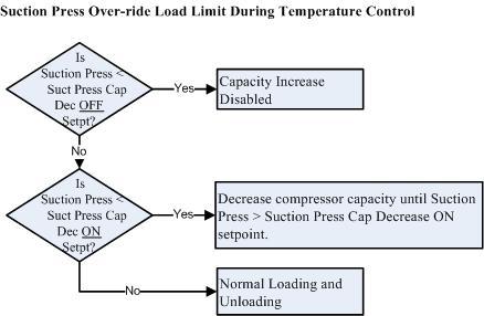
9 Operational Flow Charts 9
10 10
11 Installation Recommendations Proper Wire Sizing As a minimum, always size wire gauges as specified by the National Electrical Code (NEC) for electronic control devices. For improved noise immunity, install one size larger wire gauge than the NEC requirement to assure ample current-carrying capability Never undersize wire gauges. Voltage Source Transformers block a large percentage of Electro-Magnetic Interference (EMI). The Vilter Vission 20/20 should be isolated with its own control transformer, for the most reliable operation. 11
 emitted from the other devices connected to the secondary terminals of the transformer.")
12 Voltage Source Connecting the Vilter Vission 20/20 to breaker panels and central control transformers exposes the Vission 20/20 to large amounts of electromagnetic interference (EMI) emitted from the other devices connected to the secondary terminals of the transformer. This practice should be avoided if possible. 12
13 Grounding Continuous grounds must be run from the power company ground to the Vission 20/20. Grounds must be copper or aluminum wire. Never use conduit grounds. 13

14 Mixing Voltages Separate different voltagesfrom each other and separate AC from DC. Each voltage level must be run in separate conduit: 460 VAC 230 VAC 120 VAC 24 VAC DC signals If your plant has wire-ways or conduit trays, dividers must be installed between the different voltages. 14

15 Wiring Methods Don t Daisy-Chain control power for Vission 20/20 panels. 15
16 Best Practices DO: Keep AC wires away from circuit boards. Always run conduit into the bottom or sides of an enclosure. If the conduit must be placed in the top of an enclosure, use a water-tight conduit fitting to keep water from entering the enclosure. The Vission 20/20 is supplied with pre-punched conduit holes. Use them! DON T: Don t run wires through the Vission 20/20 enclosure that are not related to the compressor control. Don t add relays, timers, transformers, etc. in the Vission 20/20 enclosure without first checking with Vilter. Don t run conduit into the top of an enclosure. Don t run refrigerant tubing inside the enclosure. Don t drill metal enclosures without taking proper precautions to protect circuit boards from damage. 16
. 8-wire touch screen operator interface.")
17 Vission 20/20 Architecture The Vission 20/20 control panel utilizes X-86 PC technology with a Linux Operating system. The Vission 20/20 has the following attributes: Low power, Industrial rated X-86 CPU. 15 XGA, high resolution LCD display. (Outdoor viewable LCD optional). 8-wire touch screen operator interface. Flexible and expandable I/O. NEMA-4 enclosure (NEMA-4X optional). Industrial temperature range design. Touch Screen I/O I/O LCD DISPLAY I/O I/O CPU ETHERNET RS-485 USB I/O DC POWER 17
18 Digital Input/Output BOARD I/O # DESCRIPTION TYPE # 1 1 Compressor Start OUTPUT 1 2 Oil Pump Start OUTPUT 1 3 Capacity Increase OUTPUT 1 4 Capacity Decrease OUTPUT 1 5 Volume Increase OUTPUT 1 6 Volume Decrease OUTPUT 1 7 Oil Sump Heater OUTPUT 1 8 Alarm OUTPUT 2 9 Slide Valve Set point #1 (Economizer) OUTPUT 2 10 Slide Valve Set point #2 (Hot Gas) OUTPUT 2 11 Slide Valve Set point #3 OUTPUT 2 12 Slide Valve Set point #4 OUTPUT 2 13 Liquid Injection #1 OUTPUT 2 14 Liquid Injection #2 OUTPUT 2 15 Remote Enabled OUTPUT 2 16 VRS Oil solenoid for old retrofit applications OUTPUT 3 17 Comp Motor Starter Auxiliary Contact INPUT 3 18 High Level Shutdown INPUT 3 19 Oil Level Float Switch #1 INPUT 3 20 Oil Level Float Switch #2 INPUT 3 21 Remot Setpoint #1/#2 Selection INPUT 3 22 Remote Start/Stop INPUT 3 23 Remote Capacity Increase INPUT 3 24 Remote Capacity Decrease INPUT 4 25 Condenser Step #1 OUTPUT 4 26 Condenser Step #2 OUTPUT 4 27 Condenser Step #3 OUTPUT 4 28 Condenser Step #4 OUTPUT 4 29 Auxiliary Input #1 INPUT 4 30 Auxiliary Input #2 INPUT 4 31 Auxiliary Input #3 INPUT 4 32 Auxiliary Input #4 INPUT 5 33 Auxiliary Output #1 OUTPUT 5 34 Auxiliary Output #2 OUTPUT 5 35 Auxiliary Output #3 OUTPUT 5 36 Auxiliary Output #4 OUTPUT 5 37 Auxiliary Input #5 INPUT 5 38 Auxiliary Input #6 INPUT 5 39 Auxiliary Input #7 INPUT 5 40 Auxiliary Input #8 INPUT COMPRESSOR START OUTPUT When the Vission 20/20 signals the compressor to start, this output is energized. When the Vission 20/20 signals the compressor to stop, this output is de-energized. OIL PUMP START OUTPUT - When the Vission 20/20 signals the oil pump to start, this output is energized. When the Vission 20/20 signals the oil pump to stop, this output is de-energized. 18
19 CAPACITY INCREASE OUTPUT This output is only active when the compressor is running. When the Vission 20/20 determines that the compressor should increase capacity by moving the slide valve to a higher percentage, this output is energized. Once the slide valve reaches 100%, this output will not energize. CAPACITY DECREASE OUTPUT This output is only active when the compressor is running. When the Vission 20/20 determines that the compressor should decrease capacity by moving the slide valve to a lower percentage, this output is energized. Once the slide valve reaches 0%, this output will not energize. VOLUME INCREASE OUTPUT This output is only active when the compressor is running. When the Vission 20/20 determines that the compressor should increase VI by moving the volume slide to a higher percentage, this output is energized. Once the volume slide reaches 100%, this output will not energize. VOLUME DECREASE OUTPUT This output is only active when the compressor is running. When the Vission 20/20 determines that the compressor should decrease VI by moving the volume slide to a lower percentage, this output is energized. Once the volume slide reaches 0%, this output will not energize. OIL SUMP HEATER OUTPUT This output is active and energized when the oil separator temperature is lower than the oil separator temperature setpoint. It is de-energized when the oil separator temperature is higher than the oil separator temperature setpoint. ALARM OUTPUT This output is energized when the system has no alarms. If an alarm is issued, the output deenergizes and stays de-energized until the alarm condition is cleared. SLIDE VALVE SETPOINT #1 OUTPUT (ECONOMIZER) Normally used for an economizer solenoid, but could be used for other devices. When the compressor slide valve percentage is equal to or greater than slide valve set-point #1, the output is energized. When the compressor slide valve percentage is less than slide valve set-point #1, the output is de-energized. SLIDE VALVE SETPOINT #2 OUTPUT (HOT GAS) Normally used for a hot gas solenoid, but could be used for other devices. When the compressor slide valve percentage is equal to or greater than slide valve set-point #2, the output is energized. When the compressor slide valve percentage is less than slide valve set-point #2, the output is de-energized. SLIDE VALVE SETPOINT #3 OUTPUT When the compressor slide valve percentage is equal to or greater than slide valve set-point #3, the output is energized. When the compressor slide valve percentage is less than slide valve set-point #3, the output is de-energized. SLIDE VALVE SETPOINT #4 OUTPUT When the compressor slide valve percentage is equal to or greater than slide valve set-point #4, the output is energized. When the compressor slide valve percentage is less than slide valve set-point #4, the output is de-energized. LIQUID INJECTION #1 OUTPUT If the compressor has liquid injection oil cooling, this output is active. When the compressor is running and the discharge temperature is above the liquid injection temperature control set-point 5 degrees, and the oil separator temperature is above the override setpoint, then the output is energized. The output is de-energized when the discharge temperature falls below the on setpoint minus the solenoid differential. LIQUID INJECTION #2 OUTPUT Not Defined REMOTE ENABLED OUTPUT This output is energized when the Vission 20/20 panel is enabled for remote control. The compressor can be running or stopped, but is available to the remote system. If the compressor has an alarm or is placed into the manual stop position, this output is de-energized. 19
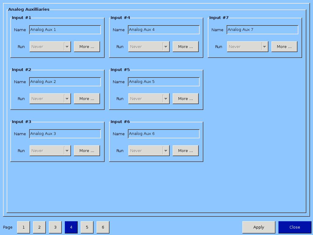
20 VRS OIL SOLENOID OUTPUT Used in VRS retrofit applications where an oil solenoid is installed in the oil line. COMP MOTOR STARTER AUXILIARY CONTACT This input looks for a feedback signal from the compressor starter, confirming that the compressor starter is energized. HIGH LEVEL SHUTDOWN INPUT This input must be energized in order for the compressor to operate. If de-energized, the compressor will shut down and issue a high level trip. OIL LEVEL FLOAT SWITCH #1 INPUT Used for Cool Compression. OIL LEVEL FLOAT SWITCH #2 INPUT Used for Cool Compression. LOCAL/REMOTE SELECT INPUT This input enables or disables remote I/O control. Energizing this input enables the Remote Capacity Increase and Remote Capacity Decrease inputs. REMOTE START/STOP INPUT If the compressor is enabled for remote I/O control, this input is enabled. Energizing this input will issue a start for the compressor as long as it is available to run. De-energizing this input stops the compressor. REMOTE CAPACITY INCREASE INPUT If the compressor is enabled for remote I/O control, this input is enabled. Operational only when the compressor is running. Energizing this input will increase the slide valve position. The slide valve will continuously increase as long as this input is energized. The slide valve will not increase when this input is de-energized. NOTE: The scan interval on the remote increase and decrease modules is approximately ONE SECOND. Please take that into account when developing a control scheme using the remote increase and remote decrease modules for compressor control. REMOTE CAPACITY DECREASE INPUT If the compressor is enabled for remote I/O control, this input is enabled. Operational only when the compressor is running. Energizing this input will decrease the slide valve position. The slide valve will continuously decrease as long as this input is energized. The slide valve will not decrease when this input is de-energized. CONDENSER STEP #1 OUTPUT This output is enabled when condenser control option is selected. A condenser fan or pump will be turned on or off by this output. CONDENSER STEP #2 OUTPUT This output is enabled when condenser control option is selected. A condenser fan or pump will be turned on or off by this output. CONDENSER STEP #3 OUTPUT This output is enabled when condenser control option is selected. A condenser fan or pump will be turned on or off by this output. CONDENSER STEP #4 OUTPUT This output is enabled when condenser control option is selected. A condenser fan or pump will be turned on or off by this output. AUXILIARY #1 thru #8 INPUT Optional inputs that can be configured as an alarm or trip. Typically connected to external switched devices. 20
21 Analog Inputs BOARD I/O DESCRIPTION TYPE # 6 1 Motor Current 4-20 ma, 0-5A 6 2 Suction Pressure 0-5V, 1-5 V, 0-10V, 4-20 ma 6 3 Discharge Pressure 0-5V, 1-5 V, 0-10V, 4-20 ma 6 4 Oil Filter Pressure 0-5V, 1-5 V, 0-10V, 4-20 ma 6 5 Oil Manifold Pressure 0-5V, 1-5 V, 0-10V, 4-20 ma 6 6 VRS Oil Injection Pressure 0-5V, 1-5 V, 0-10V, 4-20 ma 6 7 % slide Valve Position 0-5V, 4-20 ma, Potentiometer 6 8 % Volume Position 0-5V, 4-20 ma, Potentiometer 7 9 Suction Temperature 4-20 ma, RTD, ICTD 7 10 Discharge Temperature 4-20 ma, RTD, ICTD 7 11 Oil Separator Temperature 4-20 ma, RTD, ICTD 7 12 Oil Manifold Temperature 4-20 ma, RTD, ICTD 7 13 Process Temperature 4-20 ma, RTD, ICTD 7 14 Level Probe (Cool Compression) 4-20 ma 7 15 Condenser Pressure 0-5V, 1-5 V, 0-10V, 4-20 ma 7 16 Remote Set point 0-5V, 4-20 ma 8 17 Economizer Pressure 0-5V, 1-5 V, 0-10V, 4-20 ma 8 18 Chiller In Temperature 4-20 ma, RTD, ICTD 8 19 Motor Winding Temperature # ma, RTD 8 20 Motor Winding Temperature # ma, RTD 8 21 Motor Winding Temperature # ma, RTD 8 22 Auxiliary #1 0-5V, 1-5V, 0-10V, 4-20 ma, RTD, ICTD 8 23 Auxiliary #2 0-5V, 1-5V, 0-10V, 4-20 ma, RTD, ICTD 8 24 Auxiliary #3 0-5V, 1-5V, 0-10V, 4-20 ma, RTD, ICTD 9 25 Auxiliary #4 0-5V, 1-5V, 0-10V, 4-20 ma, RTD, ICTD 9 26 Auxiliary #5 0-5V, 1-5V, 0-10V, 4-20 ma, RTD, ICTD 9 27 Auxiliary #6 0-5V, 1-5V, 0-10V, 4-20 ma, RTD, ICTD 9 28 Auxiliary #7 0-5V, 1-5V, 0-10V, 4-20 ma, RTD, ICTD 9 29 Bearing Accelerometer/Temp #1 0-5V, 4-20 ma, RTD 9 30 Bearing Accelerometer/Temp #2 0-5V, 4-20 ma, RTD 9 31 Bearing Accelerometer/Temp #3 0-5V, 4-20 ma, RTD 9 32 Bearing Accelerometer/Temp #4 0-5V, 4-20 ma, RTD MOTOR CURRENT Default is a 0-5 Amp current transformer (CT). Current transformer ratio is set in the calibration screen. SUCTION PRESSURE Default signal is 4-20Ma. Suction pressure transducer range and calibration is set in the calibration screen. DISCHARGE PRESSURE - Default signal is 4-20Ma. Discharge pressure transducer range and calibration is set in the calibration screen. OIL FILTER PRESSURE - Default signal is 4-20Ma. Oil filter pressure transducer range and calibration is set in the calibration screen. 21
22 OIL MANIFOLD PRESSURE - Default signal is 4-20Ma. Oil manifold pressure transducer range and calibration is set in the calibration screen. VRS OIL INJECTION PRESSURE Default signal is 4-20Ma. VRS oil injection pressure transducer range and calibration is set in the calibration screen. % SLIDE VALVE POSITION Reads the 0-5 volt signal back from the slide position motor actuator to indicate current slide valve position. % VOLUME POSITION Reads the 0-5 volt signal back from the slide volume motor actuator to indicate current volume position. SUCTION TEMPERATURE Default signal is RTD. Suction temperature calibration is set in the calibration screen. DISCHARGE TEMPERATURE Default signal is RTD. Discharge temperature calibration is set in the calibration screen. OIL SEPARATOR TEMPERATURE Default signal is RTD. Oil separator temperature calibration is set in the calibration screen. OIL MANIFOLD TEMPERATURE Default signal is RTD. Oil manifold temperature calibration is set in the calibration screen. PROCESS TEMPERATURE Default signal is RTD. Process temperature calibration is set in the calibration screen. LEVEL PROBE (COOL COMPRESSION) Default signal is 4-20mA. Measures separator level. Level probe calibration is set in the calibration screen. CONDENSER PRESSURE Default signal is 4-20Ma. Condenser pressure transducer range and calibration is set in the calibration screen. REMOTE CAPHOLD Default signal is 4-20Ma. Active in Direct I/O mode. Adjusts the capacity of the compressor from 0-100%, proportional to the 4-20mA signal. ECONOMIZER PRESSURE Default signal is 4-20Ma. Economizer pressure transducer range and calibration is set in the calibration screen. CHILLER IN TEMPERATURE Default signal is RTD. Chiller inlet temperature calibration is set in the calibration screen. MOTOR WINDING TEMPERATURE #1 thru #3 - Default signal is RTD. One RTD is installed in each of the three motor windings to monitor motor winding temperature. AUXILIARY #1 thru #7 Flexible analog inputs that can be configured to control, alarm or trip. BEARING TEMP #1 thru #4 - Default signal is RTD. Monitors bearing temperatures in both the compressor and motor. 22
23 Analog Outputs BOARD I/O # DESCRIPTION TYPE # 10 1 Compressor VFD 4-20 ma 10 2 Condenser VFD 4-20 ma 10 3 % Slide Valve Position 4-20 ma 10 4 Motorized Valve (Cool Compression or Liquid Injection), V ma 10 5 Profile Cooler VFD (Profile only) 4-20 ma COMPRESSOR VFD 4-20mA output to control compressor motor speed with a Variable Frequency Drive (VFD). CONDENSER VFD 4-20mA output to control one condenser fan which is interleaved between the remaining condenser steps for smoother control. % SLIDE VALVE POSITION 4-20mA signal that transmits the slide valve position for remote monitoring. MOTORIZED VALVE (V+) for a cool compression compressor, this 4-20ma signal controls a motorized valve to regulate the liquid refrigerant level in the oil separator. For a liquid injection application on a standard single screw, this 4-20ma signal controls a motorized valve to regulate the liquid refrigerant injected into the compressor for oil cooling purposes. PROFILE VFD for a profile unit compressor, this signal controls the aftercooler fan speed which provides oil cooling. 23

24 Touch Screen LCD Display Main Screen The main screen gives the operator an overall view of operating parameters affecting the compressor package. This screen is displayed when maintenance items and set-points items are not being performed. The data on the screen is continuously updated. Menu Button Navigates to the menu screen for the following selections: Compressor Control Alarms and Trips Timers Compressor Scheduling Compressor Sequencing Condenser Control Service Options Instrument Calibration Slide Calibration Trend Chart Event List Input/Output States Configuration Data Backup MAINTENANCE BUTTON Navigates to the maintenance screen to allow an operator to see interval times for maintenance items and to log completed maintenance items. 24
25 LOG ON BUTTON Navigates to the log on screen which allows the operator to have access to system set-points, based on his level of security. LANGUAGE BUTTON Selects the preferred language for all screens. HELP BUTTON Provides help file notes for various screens and settings. STOP BUTTON Stops the compressor. ALARM RESET BUTTON Resets alarms and allows the compressor to be available to run. If there are issues that persist, the alarms will be re-issued and prevent the compressor from being available to run. After correcting the problem, press the alarm reset button again and the compressor will be available to run. UNIT START BUTTON Selects mode of compressor start. CAPACITY SLIDE BUTTONS Allows manual increase or decrease of the slide valve. VOLUME SLIDE BUTTONS Allows manual increase or decrease of the volume slide. Volume slide control will return to automatic operation after 5 minutes of manual inactivity. REMOTE LOCK BUTTON Prevents a remote PLC or remote computer from taking control of the panel. This allows the operator to take local control of the panel if the need arises. Indicators Hour meter in run hours Time and Date Suction pressure set-point Suction pressure and temperature Discharge pressure and temperature Oil pressure difference Oil filter pressure difference Oil injection temperature Oil separator temperature Motor amperage Process temperature Oil heater status Real time compressor and package operating conditions. Maintenance messages. Alarm and Trip Status. Data Backup 25

26 Menu Screen COMPRESSOR CONTROL - Navigates to the compressor control screen where the operator can set the variouscompressor control parameters. ALARMS AND TRIPS - Navigates to the alarms and trips screen where the operator can set the various alarm and trip parameters. TIMERS - Navigates to the timer screen where the operator can set the various time related parameters. COMPRESSOR SCHEDULING - Navigates to the compressor scheduling screen where the operator can set the control set-point schedule. (For Future Software Releases) COMPRESSOR SEQUENCING - Navigates to the compressor sequencing screen where the operator can set-up compressor to compressor sequencing. (For Future Software Releases) CONDENSER CONTROL - Navigates to the condenser control screen where the operator can set local condenser control for up to four fans and pumps. (For Future Software Releases) SERVICE OPTIONS - Navigates to the service options screen where the operator can perform package diagnostics by manually turning on digital outputs. INSTRUMENT CALIBRATION - Navigates to the instrument calibration screen where the operator can calibrate all of the system sensors. 26
27 SLIDE CALIBRATION - Navigates to the slide calibration screen where the operator can calibrate the slide and volume actuators. TREND CHART - Navigates to the trend chart screen where the operator can select up to four parameters for historical data trending. Trend charts are updated continuously. EVENT LIST - Navigates to the event list screen where the operator can view the systems events in chronological order. INPUT/OUTPUT STATES - Allows viewing of the Live Data of all analog and digital input and outputs. Also allows viewing Frozen Data of all analog and digital input and outputs at the time of the last compressor stop event. CONFIGURATION - Navigates to configuration screens where the system parameters are set-up. DATA BACKUP - Allows back of data and set-points to a handheld USB memory stick screen. (For Future Software Releases) 27
28 Compressor Control Screen This screen allows the operator to view and adjust settings that affect compressor capacity control. COMPRESSOR CONTROL Pressure/Temperature control setpoints Auto-cycle control points VFD control set-points Pump-down control setpoints Pull-down control setpoints The Vision 20/20 comes preconfigured for the type of controls that are available. The operator is able to choose the mode of control from the Compressor Control screen. This selection will typically be found on the last page of the Compressor Control screens. Typically, the operator can choose from the following parameter list: Suction Pressure SP1 (SP1 = Setpoint #1) Suction Pressure SP2 (SP2 = Setpoint #2) Process Temperature SP1 Process Temperature SP2 Discharge Pressure SP1 Discharge Pressure SP2 Once the control parameter is chosen, the appropriate setpoints are then displayed on the Compressor Control Setpoints screen. The compressor control logic will decide when to increase or decrease capacity by comparing the controlled variable to the setpoints. 28
29 TIME PROPORTIONING CONTROL Assume that Suction Pressure is the selected parameter to control compressor capacity. Time proportioning control is the method used to control the compressor slide valve position in response to a setpoint. The setpoints are; Pressure Control Setpoint (This is the target set-point.) Proportional band Dead-band Interval time Example: Setpoint = 20 psig High Proportional Band = 4 psig High Dead-band region = 4 x 0.10 = 0.4 psig Low Proportional Band = 3 psig Low Dead-band region = 3 x 0.10 = 0.3 psig Proportional Band When the suction pressure exceeds the dead-band in either direction, it then enters the proportional band area. The Capacity Increase/Decrease Proportional Band defines the range of pressure in which corrective action will be taken to bring the suction pressure back to within the setpoint dead-band. This is done by pulsing the appropriate capacity motor. The length of the pulse is in direct proportion to the amount of deviation that the suction pressure is from the setpoint dead-band. Dead Band A region around the setpoint automatically exists and defines a range around the setpoint where the pressure is allowed to deviate without the program taking any corrective action. This allows small variances of pressure around the setpoint, and reduces capacity hunting from occurring. The dead-band regions are always defined as 10% of the proportional band region values. Interval Time The Capacity Increase/Decrease Interval Time is the time interval that the program will use to look and determine if a capacity increase or decrease pulse is required to bring the Suction Pressure back to the setpoint dead-band area. The length of the pulse is in direct proportion to the amount of deviation that the suction pressure is from the setpoint dead-band. The formula used to determine the length of pulse is described as: 0.5 second pulse for every 10% away from dead-band region. 0 second pulse = suction pressure within set-point dead-band 0.5 second pulse = suction pressure is in the proportional band region and 10% or less from the dead-band region. 1 second pulse = suction pressure is in the proportional band region and is > 10% and < 20% from the deadband region. 1.5 second pulse = suction pressure is in the proportional band region and is > 20% and < 30% from the deadband region. 2 second pulse = suction pressure is in the proportional band region and is > 30% and < 40% from the deadband region. 2.5 second pulse = suction pressure is in the proportional band region and is > 40% and < 50% from the deadband region. 3 second pulse = suction pressure is in the proportional band region and is > 50% and < 60% from the deadband region. 29
30 3.5 second pulse = suction pressure is in the proportional band region and is > 70% and < 80% from the deadband region. 4 second pulse = suction pressure is in the proportional band region and is > 80% and < 90% from the deadband region. 4.5 second pulse = suction pressure is in the proportional band region and is > 90% and < 100% from the dead-band region. 5 second pulse = suction pressure is beyond the proportional band region ( > 100% from the dead-band region.) Auto-Cycle Setpoints The auto-cycle setpoints define the control points in which the compressor will automatically cycle on and off when the compressor has been placed into Auto mode. These setpoints can be enabled or disabled using the check box. A delay can be entered to momentarily delay the start or stop from immediately occurring when the pressure reaches setpoint. If a compressor shut down is desired on a suction pressure drop and a manual reset is required, set the OFF value below the Low Suction Pressure safety trip value. This will shut down the compressor and a Reset will be required to restart it. [x] Enable = enables the Auto-cycle control. Uncheck the box to disable the Auto-cycle set-points. Start Pressure = When the suction pressure meets or exceeds this set-point, the compressor will start. Start Delay = delays the compressor from starting when the suction pressure meets or exceeds this set-point. Stop Pressure = When the suction pressure meets or falls below this setpoint, the compressor will stop. Stop Delay = delays the compressor from starting when the suction pressure meets or exceeds this set-point. Minimum Slide Position = The minimum capacity slide position that the compressor is allowed to run at. NOTE: When the Pump-down Feature is enabled, the Auto-cycle setpoints are automatically disabled. Pumpdown mode will cause the compressor to cycle off via the Pump-down Stop Pressure setpoint, and will not allow the compressor to start again. VFD Settings (PID settings for Motor Speed Control) When a VFD is used on the compressor motor, the speed of the VFD is controlled using a PID algorithm. The setpoints are: P = Proportional (gain) set-point. Used to adjust the motor speed action in direct proportion to the difference between the control set-point and the process variable (SP - PV error). This is a unit-less quantity and is used for coarse adjustment. Use an initial setting of This set-point should be set to the lowest value that gives adequate control system response. Increasing the proportional setting increases the control system s sensitivity to small process fluctuations and the tendency to hunt. I = Integral (reset) set-point. Used to adjust the capacity control action, integrating the error over time, to account for a small error that has persisted for a long time. This quantity is used for fine adjustment. Use and initial setting of 4.00 min. This set-point is used to smooth out process variations. This set-point should be set high enough to prevent hunting but not too high or it will cause control system overshoot. D = Derivative (rate) set-point. Used to adjust the capacity control action, accounting for how fast the error is changing, positively or negatively. A standard PID loop variable, it is not used for our applications. Use an initial setting of 0.00 min (Always). 30
31 OTHER SETPOINTS THAT MIGHT BE REQUIRED FOR MOTOR PID CONTROL Max Change Rate = The VFD motor PID output is limited by this parameter to prevent large instantaneous changes to the motor speed. Dead-band = used to establish a range on either side of the set-point in which no capacity control action will occur. Initial Setpoint: 2.5% Min Spd Point = used to prevent the compressor from running too slowly which can adversely affect hydrodynamic sealing, heat transfer and lubrication. Initial Setpoint: 50% Setpoint Ramping Rate = used to control how fast the compressor responds to the required capacity control action. Initial Setpoint: 20 Unit/min Unloading Rate = used to control how fast the unloading action occurs due to a safety override. Initial Setpoint: 20%/min 31
32 Pump-Down and Pull-Down Setpoints Pump-down (For Future Software Releases) The Pump-down set-points define a method of pumping down a chiller, which is to draw off refrigerant from the chiller. The purpose is to prevent liquid refrigerant from developing in the chiller during an off cycle, and then being drawn into the compressor when it restarts. This feature can be enabled or disabled from this menu. If Pump-down is enabled, this feature will only function when the compressor is in Auto mode. If Pump-down is enabled, then: The Auto-cycle feature is disabled automatically. Normally, the Pump-down Stop set-point will be set lower than the Auto-cycle Stop set-point. Therefore, as the suction pressure is pulled down, the compressor is prevented from shutting down prematurely via the Auto-cycle Stop set-point by automatically disabling the Auto-cycle feature. The compressor will be placed into Stop mode after the suction pressure is equal to, or goes below the Pump-down Stop pressure. Enable = enables the Pump-down. Uncheck the box to disable the Pump-down setpoints. Pump-down Stop Pressure = this setpoint defines the suction pressure value in which the compressor will cycle off. Normally, this set-point is set below the Suction Pressure Auto-cycle Stop Pressure Set-point. 32
33 Stop Delay = delays the compressor from stopping when the suction pressure is equal to or less than the stop pressure. Minimum Slide Position = The minimum capacity slide position that the compressor is allowed to run at. By forcing the compressor capacity to operate at a value above minimum, we insure that the suction pressure will be pulled down to the Stop pressure setpoint value. Pull-down The Pull-down set-points define a method of slowly pulling the suction pressure down from a high value. This is sometimes required on systems that have liquid recirculation systems. On such systems, if the suction pressure is pulled down too fast, the pumps can cavitate, causing vibration and damage to the pumps. Pull-down is also required for new plant startups. Pulling the temperature of new buildings down too quickly can cause structural damage, so limiting the suction pressure pull-down rate will prevent this, allowing time to de-humidify the rooms as the temperature in the rooms are pulled down. The pull-down feature provides a method to slowly pull the suction pressure down to operating conditions. The pull-down method used is to step the suction pressure down over a defined time interval. When the time interval expires, another step is taken. Example: Assume the suction pressure is at 80 psig and the set-point we want to get to is 20 psig. This defines a change of 60 psig. We want to allow 48 hours of pull-down time. Pick a reasonable step pressure of 5 psig for every step. Number of steps = ( 60 psig change * 1 step/5 psig) = 12 steps Delay per step = (48 hours / 12 steps) = 4 hours/step For the first 4 hours, the compressor runs at 75 psig. next 4 70 psig next 4 65 psig and so forth. After the 12th step (running at 25 psig), 48 hours will have elapsed, and the new setpoint becomes 20 psig, achieving the 20 psig setpoint after 48 hours. After the pull-down setpoint equals or is less than the control setpoint, the pull-down feature disables itself. Enable = Enables Pulldown control. Uncheck the box to disable the Pull-down setpoints. Step Pressure = This setpoint defines the step increments which the suction pressure will be controlled at. Delay Per Step = Defines the time increment at which the compressor will be controlled for each step. 33
34 Additional Control Setpoints Misc. Control Control Mode = Drop-down box allows selection of current operating mode, from the list of allowable modes. High Motor Amps (Unloading) = This control feature will limit the compressor capacity when the compressor motor amps reaches these load limiting set-points. When the set-points are set properly, this control feature will prevent the motor from operating at excessive high amp conditions, which will help to prevent the compressor starter from stopping the compressor on motor overload conditions. Stop Load = prevents the compressor from loading when the set-point is reached. For a 1.15 SF motor, this value is the FLA value stamped onto the motor nameplate. Force Unload = forces an unload condition when this set-point is reached. For a 1.15 SF motor, this value is FLA value (from motor nameplate) x The unload pulse is released when the motor amps lands just above the FLA setting. High Discharge Pressure (Unloading) = This control feature is active in Suction Pressure or Process Temperature Capacity Control mode. This control feature will limit the compressor from loading when the compressor discharge pressure reaches these load limiting conditions. When the set-points are set properly, this control feature will prevent the compressor from experiencing excessive high discharge pressure that could result in a high discharge pressure failure. The high discharge pressure unloading set-points over-ride the Suction Pressure or Process Temperature Capacity Control Set-points. 34
35 Stop Load = prevents the compressor from loading when the set-point is reached. Set this set-point above normal discharge operating conditions. This set-point should only become active if normal condenser control is not functioning properly, which will cause discharge pressure to become abnormally high. Force Unload = forces an unload condition when this set-point is reached. This set-point should be set above the Stop Load set-point. This set-point will cause the compressor to unload until the discharge pressure lands just above the Stop Load set-point. Low Suction Pressure (Unloading) = This control feature is active in Discharge Pressure or Process Temperature Capacity Control mode. This control feature will limit the compressor from loading when the compressor suction pressure reaches these load limiting conditions. When the set-points are set properly, this control feature will prevent the compressor from experiencing excessive low suction pressure that could result in a low suction pressure failure. The low suction pressure unloading set-points over-ride the Discharge Pressure or Process Temperature Capacity Control Setpoints. Stop Load = prevents the compressor from loading when the set-point is reached. Set this set-point below normal suction operating conditions. Force Unload = forces an unload condition when this set-point is reached. This set-point should be set below the Stop Load set-point. This set-point will cause the compressor to unload until the suction pressure lands just above the Stop Load set-point. Oil Separator Heater Temperature = These control limits determines when the oil separator heater is turned on and off. A decrease in oil separator temperature below he ON set point turns on the oil separator heater. On an increase in oil separator temperature above the OFF set-point turns off the oil heater. Liquid Injection Solenoid Control Temp = These set-points determine when the Liquid Injection Solenoid is turned on and off. The solenoid will always be off when the compressor is off. This solenoid can be controlled via the Oil Injection Temperature or the Oil Separator Temperature. This selection in made in the Configuration screen. Oil Pump Restart = The oil pump can be selected either as a full time oil pump (booster applications) or as a part-time oil pump (high stage applications). The selection is accomplished from the Configuration Menu. When the oil pump is selected as a part-time oil pump, then these set-points determine when the oil pump is turned on and off - based on the pressure ratio across the compressor. The pressure ratio is calculated using the absolute discharge pressure and the absolute suction pressure. The pump is cycled on when the pressure ratio is equal to or less than the ON set-point. The pump is cycled off when the pressure ratio is equal to or greater than the OFF setpoint. P.R = Discharge Pressure / Suction Pressure Volume Slide Adjustment Factor= This value is normally zero. It can be set to a non-zero value to permit a repositioning of the volume slide if it is found that the volume slide is not being positioned such to allow the compressor to run at the most efficient point. Economizer Solenoid = These setpoints determine when the economizer solenoid is turned on and off. When the percentage of compressor capacity is equal to or below the OFF set-point, then the solenoid is turned OFF. When the compressor capacity is equal to or above the ON set-point, then the solenoid is turned ON. Hot Gas Bypass Solenoid = These setpoints determine when the hot gas solenoid is turned on and off. When the compressor capacity is equal to or below the ON set-point, then the solenoid is turned ON. When the percentage of compressor capacity is equal to or above the OFF set-point, then the solenoid is turned OFF. 35
36 Current Transformer Ratio : The value entered must agree with the Current Transformer Ratio label on the current transformer being used. The current transformer is mounted in the compressor motor conduit box. The ratio is stated in terms of Primary amps : Secondary amps. The secondary value is always 5 amps. The primary number for the current transformer is selected based on the size of the motor being used. The primary number is the value that is entered for this set-point. For example if the current transformer ratio label reads 250:5, enter 250. Low Suction Pressure Load Limit : Active in Discharge Pressure Capacity Control mode only. These setpoints limit the compressor from loading at low suction pressure conditions. They over-ride the discharge pressure capacity control setpoints. When the suction pressure is at or below the STOP LOAD setpoint then the compressor will not be allowed to load any further. If the suction pressure continues to fall, and is at or below the UNLOAD setpoint, then the capacity of the compressor will decrease until the suction pressure rises to a point that is between the UNLOAD and the STOP LOAD setpoint. 36
37 Alarms and Trips Screen This screen allows the operator to view and adjust settings for compressor safety and alarm settings. Alarms and Trips defined are: Low Suction Pressure set-points High Discharge Pressure set-points High Process Temperature set-points Low Process Temperature set-points Low Suction Temperature set-points High Discharge Temperature set-points Low Oil Separator Start Temperature set-points Low Oil Separator Run Temperature set-points Low Oil Injection Temperature set-points High Oil Injection Temperature set-points Pre-lube Oil Pressure set-points Run Oil Pressure set-points High Start Filter Differential Pressure set-points High Run Filter Differential Pressure set-points High Motor Amperage set-points 37
38 Low Suction Pressure Alarm and Trip = This is the low suction pressure safety. This safety is active in both temperature and pressure control modes. An alarm or trip will be active on a drop in suction pressure at or below the set-point value. High Discharge Pressure Alarm and Trip = This is the high discharge pressure safety. The alarm or trip will be active on a rise in discharge pressure at or above the set-point value. High Process Temperature Alarm = This alarm is active when the process temperature is at or above the setpoint value. There is no TRIP set-point. Low Process Temperature Alarm and Trip = This is the low control temperature safety. This safety is active when process temperature control has been selected in the Control Mode dropdown selection found in the Compressor Control Menu. An alarm or trip will be active on a drop in process temperature below the set-point value. 38
39 Alarms and Trips Low Suction Temperature = This is the low suction temperature safety. The alarm or trip will be active if the suction temperature should drop to a value that is at or below the set-point value. High Discharge Temperature : This is the high discharge temperature safety. The alarm or trip will be active if the discharge temperature should rise to a value that is at or above the set-point value. Low Oil Separator Start Temperature = This is the starting low oil separator temperature safety. The compressor is prevented from starting or running if the oil in the separator is below the trip value. After a time delay (setting of the Oil Separator Temperature Safety Changeover timer), this safety is deactivated and the Low Oil Separator Run Temperature alarm and safety set-points become active. Low Oil Separator Run Temperature = This is the running low oil separator temperature safety. After a time delay, (setting of the Oil Separator Temperature Safety Changeover timer), the Low Oil Separator Start Temperature is bypassed and Low Oil Separator Run Temperature alarm and safety set-points become active. The alarm or trip will be active if the oil temperature in the separator drops to a value that is at or below the set-point value. Low Oil Injection Temperature = This is the low oil injection safety. The alarm and trip set-points are bypassed at start for a time period (setting of the Oil Injection Temperature Safety Changeover timer). The alarm and trip will be active after the time delay has expired. High Oil Injection Temperature = This is the high oil injection temperature safety. The alarm or trip will be active on a rise in oil injection temperature at a value at or above the set-point value. 39
40 Pre-lube Oil Pressure = This is the pre-lube oil pump failure safety. If the pre-lube oil pressure does not rise above the alarm setting for a time exceeding the Minimum Pre-lube Time and the pump run runs longer than the Pre-lube Pump Time Limit, an alarm or trip will occur. These time limits are set on the Timer menu screen. Prelube oil pressure is defined as manifold pressure minus discharge pressure. The purpose of this safety is to insure that we have oil being injected into the compressor during the starting of the compressor - to insure adequate lubrication. Low (Run) Oil Pressure = This is the running oil pressure safety. The normal alarm and trip set-points of this safety are massaged as soon as the compressor starts. The Pre lube Oil Pressure Alarm and Trip set-points are jammed into this safety set-points for a time of the Oil Pressure Bypass timer (typically 60 seconds). After this timer expires, then the set-points return back to the normal settings. The action of massaging the set-points for about a minute allows the (Run) Oil Pressure to build up to normal running pressures after the compressor starts. After the Oil Pressure Bypass Timer has expired, the Oil Pressure must be above the normal set-points, or else an Alarm or Trip will occur. An alarm or trip will be active if the oil pressure should drop below the normal set-point values after the Oil Pressure Bypass timer has expired. This time limit is set on the Timer menu screen. Run oil pressure is defined as manifold pressure minus suction pressure. High Filter Differential Pressure Start = This safety allows a higher than normal filter differential pressure to exist during the first minute after a compressor starts. This allows time for cold oil that is present in the oil piping and filters to be passed and replaced with warmer oil. After a time delay (setting of the Filter Diff Pressure Safety Changeover timer), then this safety is deactivated and the High Filter Differential Pressure-Run alarm and safety set-points become active. An alarm or trip will be active if the filter differential (= Filter Inlet Pressure minus Filter Outlet Pressure) exceeds by the set-point value. High Filter Differential Pressure Run = This safety set-point is active when the compressor has started and the Filter Diff Pressure Safety Changeover timer has timed out. An alarm or trip will be active if the filter differential (= Filter Inlet Pressure minus Filter Outlet Pressure) exceeds by the set-point value. High Motor Amps : This safety set-point is active after the Volume Decrease At Start Timer expires (this timer is not settable by the operator). A trip will occur if the motor amperage exceeds the safety set-point value. For a motor with a 1.15 Service Factor, the trip set-point should be set at 125% of the motor full load amperage value. The alarm set-point should be set at 120% of the motor full load amperage value. 40
41 Timers This screen allows the operator to view and adjust timer settings associated with compressor operation. Timers defined are: Capacity Increase Start Delay Minimum Compressor Pre lube Time Low Oil Pressure Safety Changeover High Filter Differential Pressure Safety Changeover Low Oil Separator Level Safety Changeover Low Oil Separator Temp Safety Changeover Low Oil Injection Temp Safety Changeover Max Restart after Power Failure Hot Starts per Hour True Anti-Recycle Timer Accumulative Anti-Recycle Timer Capacity Increase Start Delay = At compressor startup, the capacity slide position is held at minimum position for this time period. This is to allow compressor and system conditions to stabilize. After the timer expires, the slide is free to move in accordance to the system demands. Minimum Compressor Pre-lube Time = This is the length of time the oil pump will run, after establishing Prelube Oil Pressure, to prime the oil circuit before starting the compressor. 41
42 Low Oil Pressure Safety Changeover = This is the length of time in which the normal Low (Run) Oil Pressure set-points will be massaged by the values of the Pre lube Oil Pressure set-points. After the timer has expired, the normal Low Oil Pressure set-points become active. High Filter Differential Pressure Safety Changeover = This timer bypasses the High Filter Differential Run Pressure safety settings when the compressor starts. It defines how long the High Filter Differential Start Pressure set-points will be active after the compressor starts. After the timer has expired, then the High Filter Differential Run Pressure safety set-points are active. Low Oil Separator Level Safety Changeover Timer = This timer bypasses the low oil level switch for momentary drops in the oil level. This timer activates when the low oil level switch opens, and deactivates when the switch closes. If the switch is still open after the timer has timed out, the compressor will be shut down and a trip message will be displayed. This timer is available if the unit is equipped with a low oil separator float switch (the oil level switch is standard on all liquid injection units and optional on all others). Low Oil Separator Temperature Safety Changeover = This timer allows Low Oil Separator Start Temperature safety set-point to protect the compressor against cold oil during starting. After the timer has expired, the Low Oil Separator Run Temperature is then active. Low Oil Injection Temperature Safety Changeover = This timer bypasses the Low Oil Injection Temperature Safety set-point during start-up, to allow any cold oil in the oil lines and filter to pass. After the timer expires, the Low Oil Injection Temperature safety is active. Max Restart After Power Failure = This timer forces the compressor to wait for the set time period after a power failure before it can be started automatically. By staggering the time settings of this timer between other compressor panels, the compressors can be allowed to start automatically, one at a time, after a power failure. This will prevent excessive load demand on the power system that could occur if all of the compressor equipment were to start at the same time. The Power-up Auto Re-Start [x]enable option must be selected on the Timer screen for this option to be active. Hot Starts/Hr Counter = This counter counts compressor starts. After every start, a one-hour timer is reset and starts timing. If the timer times out, the hot starts counter is reset. When the counter reaches its preset value, it will not allow another compressor start until the one-hour timer times out and resets the counter. The hot starts counter, therefore, will be reset when the time between compressor starts total one hour. This counter allows repetitive compressor starts, but once the counter has reached its set point, it requires a onehour window between compressor starts in order for the counter to be reset. 42
43 Timers True Anti-Recycle Timer = Once the compressor turns off, this timer will keep the compressor off for the setting of the True Anti-Recycle Timer. This timer is used to prevent short cycling of the compressor. Accumulative Anti-Recycle Timer = This timer also forces a specified time between compressor starts. When the compressor starts, the timer resets and starts timing and accumulates running time. Once the compressor shuts down, it will not be allowed to restart for the remainder of time left on the Accumulative Anti-Recycle Timer. Unlike the True Anti-Recycle Timer, if the compressor has run for a time period that exceeds the setpoint of the Accumulative Anti-Recycle Timer, then when the compressor shuts down, it will be allowed to restart immediately. As an example: Accumulative Anti-Recycle Timer setting = 20 minutes. Assume the compressor starts and runs for 15 minutes then shuts down. The next start can occur in (20 minutes - 15 minutes of runtime = 5 minutes) The compressor restart options (Hot Starts or Anti-Recycle Timers) are selected from the Configuration menu. One additional Anti-Recycle Timer is selected from the Configuration menu, which is the Modified Anti- Recycle timer. Modified Anti-Recycle Timer = This timer has no direct set-point. It is defined as a combination of the True Anti-Recycle Timer and the Accumulative Anti-Recycle Timer. Normally when the Modified Anti- Recycle Timer function is selected from the Configuration menu, the timer functions as a True Anti-Recycle timer and uses the set-point of the True Anti-Recycle timer. However if the operator presses the stop button, or if a failure occurs, then the Modified Anti-Recycle Timer function switches to activate the Accumulative Anti-Recycle Timer. As the definition of the Accumulative Anti-Recycle Timer states, now the compressor will be allowed to restart when the present accumulated runtime and the present accumulated off time meets or exceeds the setting of the Accumulative Anti-Recycle Timer. 43
44 Service Options This screen allows the operator to force digital outputs ON for diagnostic purposes. If you choose to exit this menu while an output is still forced on, the output will be unforced before the menu exits. Note: The forcing of the compressor output will be limited to a bump for the purposes of determining motor rotation direction. 44
45 Instrument Calibration 45
46 Slide Calibration Vilter Slide Valve Actuator Calibration Procedure for Optical Style Motors Assuming that the ACTUATOR motors have not been calibrated, the transmitter output of the ACTUATOR motor will fluctuate wildly until they are calibrated. To prevent damage to ACTUATOR motors, do not connect the Power Cable (Yellow TURCK cable) or the Position Transmitter Cable (Gray TURCK cable) until instructed to do so in this procedure. 1. Open the plastic cover of the capacity motor by removing the four #10 Pan Head Phillips screws. Gently lift the cover and tilt it toward the TURCK connectors. Raise the cover enough to be able to press the blue calibrate button and to be able to see the red LED on the top of the assembly. CAUTION: Handling the cover too aggressively may break the four wires attaching the cover-mounted connector to the circuit board. 2. Remove actuator motor cover(s). 3. Log In on the Vission 20/ From the main screen select the Menu button. 5. On the menu screen select the Slide Calibration button. 46
47 Remove Cover Press Down On Photochopper When the Slide Valve Calibration screen appears, then you can safely connect the Power Cable (Yellow TURCK cable) and the Position Transmitter Cable (Gray TURCK cable) to the Capacity motor. Press + or - to move the slide valves to check the rotation. (See Table 1 below for proper shaft rotation). If for any reason the + or - command on the panel does not correspond to the slide increase or decrease, swap the blue & brown wires of the Yellow TURCK cable in the control panel to reverse the rotation of the motor. CAUTION: DO NOT CONTINUE TO ENERGIZE THE ACTUATOR MOTOR AFTER THE SLIDE HAS REACHED THE MECHANICAL STOP. Doing so may cause mechanical damage to the motor or shear the motor shaft key. When the slide has reached the mechanical stop position, press the button in the center of the photo chopper to release the brake, and thereby release the tension on the actuator motor. Then use the + button to pulse the motor so that the capacity slide is just off of its minimum position and there is no tension on the motor shaft. 7. Quickly press and release the BLUE CALIBRATION BUTTON on the ACTUATOR motor once. The red LED will now flash at a slower rate. This now instructs the ACTUATOR motor that this point is the minimum slide position. This point will correspond to 0 volts AFTER the ACTUATOR calibration procedure is completed. 8. Use the + button on the microprocessor to drive the capacity slide to its maximum mechanical stop position. This will be apparent by a slowing of the motor rotation and a winding sound from the actuator motor. When you hear the motor wind-up, release the + button. CAUTION: DO NOT CONTINUE TO ENERGIZE THE ACTUATOR MOTOR AFTER THE SLIDE HAS REACHED THE ME- CHANICAL STOP. Doing so may cause mechanical damage to the motor or shear the motor shaft key. When the slide has reached the mechanical stop position, press the button in the center of the photo chopper to release the brake, and thereby release the tension on the actuator motor. Then use the - button to pulse the motor so that the capacity slide is just off of its maximum position and there is no tension on the motor shaft. 9. Quickly press and release the BLUE CALIBRATION BUTTON on the ACTUATOR motor once. The red LED will stop flashing. This now instructs the ACTUATOR motor that this point is the maximum slide position. This point corresponds to 5 volts. The ACTUATOR calibration procedure is completed. Now the Capacity Channel is automatically calibrated based on the calibration settings made to the actuator. 10. Gently lower the plastic cover to where it contacts the base and o-ring seal. After making sure that the cover is not binding, gently tighten the four # 10 Phillips screws. CAUTION: it is possible to crack the plastic cover by over tightening the screws. Repeat the same procedure for the Volume slide motor 6. Quickly press and release the BLUE CALIBRATION BUTTON on the AC- TUATOR motor once. This instructs the ACTUATOR motor to enter the calibration mode. The red LED on the actuator control board will begin flashing. Use the - button on the microprocessor panel to drive the capacity slide to its minimum mechanical stop position. This will be apparent by a slowing of the motor rotation and a winding sound from the actuator motor. When you hear the motor wind-up, release the - button. 47
48 Command Shaft Rotation TABLE 1. VSS / VSR / VSM COMMAND SHAFT ROTATION AND TRAVEL COMMAND SHAFT ROTATION NO. OF TURNS / ROTATION ANGLE / SLIDE TRAVEL COMP. CAPACITY VOLUME CAPACITY VOLUME MODEL INC DEC INC DEC TURNS/ANGLE/TRAVEL TURNS/ANGLE/TRAVEL VSR 111 CCW CW CCW CW 0.91 / 328 / / 187 / VSR 151 CCW CW CCW CW 0.91 / 328 / / 187 / VSR 221 CCW CW CCW CW 0.91 / 328 / / 187 / VSR 301 CCW CW CCW CW 0.91 / 328 / / 187 / VSS 451 CCW CW CCW CW 0.91 / 328 / / 187 / VSS 601 CCW CW CCW CW 0.91 / 328 / / 187 / VSS 751 CW CCW CW CCW 1.09 / 392 / / 227 / VSS 901 CW CCW CW CCW 1.09 / 392 / / 227 / VSS 1051 CW CCW CW CCW 1.22 / 439 / / 266 / VSS 1201 CW CCW CW CCW 1.22 / 439 / / 266 / VSS 1501 CW CCW CC CCW 1.36 / 490 / / 295 / VSS 1801 CW CCW CW CCW 1.36 / 490 / / 295 / VSM 71 CCW CW CCW CW 0.80 / 288 / / 162 / VSM 91 CCW CW CCW CW 0.80 / 288 / / 162 / VSM 101 CCW CW CCW CW 0.80 / 288 / / 162 / VSM 151 CCW CW CCW CW 0.80 / 288 / / 162 / VSM 181 CCW CW CCW CW 0.80 / 288 / / 162 / VSM 201 CCW CW CCW CW 0.80 / 288 / / 162 / VSM 301 CCW CW CCW CW 0.80 / 288 / / 162 / VSM 361 CCW CW CCW CW 0.80 / 288 / / 162 / VSM 401 CCW CW CCW CW 0.80 / 288 / / 162 / VSM 501 CW CCW CW CCW 0.91 / 328 / / 187 / VSM 601 CW CCW CW CCW 0.91 / 328 / / 187 / VSM 701 CW CCW CW CCW 0.91 / 328 / / 187 / NOTES: The manual operating shaft on the gear motor should be turned the opposite direction of the desired command shaft rotation. The capacity and volume control motors are equipped with a brake, if it is necessary to operate the control motors manually, the brake must be disengaged. The brake can be disengaged by pushing on the motor shaft on the cone end. The shaft should be centered in its travel. Do not use excessive force manually operating the motor or damage may result. 48
49 Slide Valve Operation The slide valve actuator is a gear-motor with a position sensor. The motor is powered in the forward and reverse directions from the main computer in the control panel. The position sensor tells the main computer the position of the slide valve. The main computer uses the position and process information to decide where to move the slide valve next. The position sensors works by optically counting motor turns. On the shaft of the motor is a small aluminum photochopper. It has a 180 degree fence that passes through the slots of two slotted optocouplers. The optocouplers have an infrared light emitting diode (LED) on one side of the slot and a phototransistor on the other. The phototransistor behaves as a light controlled switch. When the photochopper fence is blocking the slot, light from the LED is prevented from reaching the phototransistor and the switch is open. When photochopper fence is not blocking the slot, the switch is closed. This scheme is not foolproof. If the motor is moved manually while the power is off or the motor brake has failed, allowing the motor to free wheel for too long after the position sensor looses power, the actuator will become lost. A brake failure can sometimes be detected by the position sensor. If the motor never stops turning after a power loss, the position sensor detects this, knows it will be lost, and goes immediately into calibrate mode when power is restored. As the motor turns, the photochopper fence alternately blocks and opens the optocoupler slots, generating a sequence that the position sensor microcontroller can use to determine motor position by counting. Because the motor is connected to the slide valve by gears, knowing the motor position means knowing the slide valve position. During calibration, the position sensor records the high and low count of motor turns. The operator tells the position sensor when the actuator is at the high or low position with the push button. Refer to the calibration instructions for the detailed calibration procedure. The position sensor can get lost if the motor is moved while the position sensor is not powered. To prevent this, the motor can only be moved electrically while the position sensor is powered. When the position sensor loses power, power is cut to the motor. A capacitor stores enough energy to keep the position sensor circuitry alive long enough for the motor to come to a complete stop and then save the motor position to non-volatile EEPROM memory. When power is restored, the saved motor position is read from EEPROM memory and the actuators resumes normal function 49
50 Slide Valve Trouble Shooting Guide Problem Reason Solution The actuator cannot be calibrated The actuator goes into calibration mode spontaneously The actuator goes into calibration mode every time power is restored after a power loss 50 Dirt or debris is blocking one or both optocoupler slots The photochopper fence extends less than about half way into the optocoupler slots The white calibrate wire in the grey Turck cable is grounded Dirt and/or condensation on the position sensor boards are causing it to malfunction The calibrate button is stuck down The position sensor has failed Push button is being held down for more that ¾ second when going through the calibration procedure The white calibrate wire in the grey Turck cable is grounding intermittently A very strong source of electromagnetic interference (EMI), such as a contactor, is in the vicinity of the actuator or grey cable There is an intermittent failure of the position sensor The motor brake is not working properly (see theory section above.) Clean the optocoupler slots with a Q-Tip and rubbing alcohol. Adjust the photochopper so that the fence extends further into the optocoupler slots. Make sure the motor brake operates freely and the photochopper will not contact the optocouplers when the shaft is pressed down. Tape the end of the white wire in the panel and make sure that it cannot touch metal Clean the boards with an electronics cleaner or compressed air. Try to free the stuck button. Replace the actuator. Depress the button quickly and then let go. Each ¾ second the button is held down counts as another press. Tape the end of the white wire in the panel and make sure that it cannot touch metal. Increase the distance between the EMI source and the actuator. Install additional metal shielding material between the EMI source and the actuator or cable. Replace the actuator. Get the motor brake to where it operates freely and recalibrate.
51 Problem Reason Solution The actuator does not transmit the correct position after a power loss The motor was manually moved while the position sensor was not powered. The motor brake is not working properly The position sensor s EEPROM memory has failed Recalibrate. Get the motor brake to where it operates freely and then recalibrate. Replace the actuator. There is a rapid clicking noise when the motor is operating The motor operates in one direction only The motor will not move in either direction The photochopper is misaligned with the slotted optocouplers The photochopper is positioned too low on the motor shaft. A motor bearing has failed There is a loose connection in the screw terminal blocks There is a loose or dirty connection in the yellow Turck cable The position sensor has failed There is a broken motor lead or winding The thermal switch has tripped because the motor is overheated Any of the reasons listed in The motor operates in one direction only The command shaft is jammed Broken gears in the gearmotor Try to realign or replace the actuator. Adjust the photochopper so that the fence extends further into the optocoupler slots. Replace the actuator. Tighten. Clean and tighten. Replace the actuator. Replace the actuator. The motor will resume operation when it cools. This could be caused by a malfunctioning control panel. Consult the factory. See above. Free the command shaft. Replace the actuator. The motor runs intermittently, several minutes on, several minutes off Motor is overheating and the thermal switch is tripping This could be caused by a malfunctioning control panel. Consult the factory. 51
52 Problem Reason Solution The motor runs sporadically The motor runs but output shaft will not turn Bad thermal switch Any of the reasons listed in The motor will not move in either direction Stripped gears inside the gear motor or the armature has come un-pressed from the armature shaft Replace the actuator. See above. Replace the actuator. 52

53 Trend Chart This screen allows the operator to view and adjust settings for the trend chart. The trend analysis screen shows recorded data for problem analysis or tuning improvements. A logging buffer holds 30 minutes of data for 13 variables sampled at 10 second intervals. When the logging buffer fills with 30 minutes of data, it is automatically transferred to a file, which will can up to 120 hours of accumulated data. When the file has accumulated 120 hours of data, and the logging buffer has filled with another 30 minutes of data, the oldest data in the file is dumped, and the newest 30 minute data is added to the file. When the trend chart screen is opened, this logging data is copied to a display buffer and logging continues uninterrupted. The data available for display in this display buffer is 120 hours maximum. The sample of data in the display buffer is not altered by selection of a different variable to view. It is only discarded when the user exits the trend chart screen, or when the control is powered down. Up to 4 variables can be selected for plotting at one time. Each is assigned one of 4 colors - the plotted trace and the vertical axis labels for a variable will be in its assigned color. You can move from viewing the plot to selecting which variables and time interval to show as often as necessary. A start and stop button allows you to stop the trending if desired. When the stop button is pressed, you are asked to provide a name for a file which will contain the saved trend data. A Trace button and a Hold button allows you to move a cursor line across all four trend lines and receive a readout of all four variables at the point in time of the cursor position. The hold button stops the data from advancing on the display - but doesn t stop the background trending. The vertical axis scaling and offset for each variable plotted is based on its range of values over the entire display buffer sample. This helps to magnify small changes in a variable and to keep one plot trace from falling on top of another, but it can be misleading. Look at the range of the vertical axis for a variable and try to visualize how far off screen the zero point would be. 53
54 Event List Screen This screen is designed to display compressor events, in chronological order and time stamped. The top of the list shows the most recent event followed by older events. 54
55 Input / Output States This screen allows showing of Live Data of all analog points and digital points being monitored, or of Frozen Data. Frozen data is a snapshot of the values of the analog points and digital points at the time in which the compressor last shutdown, either by normal shutdown methods or via a fault condition. The Live Data is the current analog reading. 55
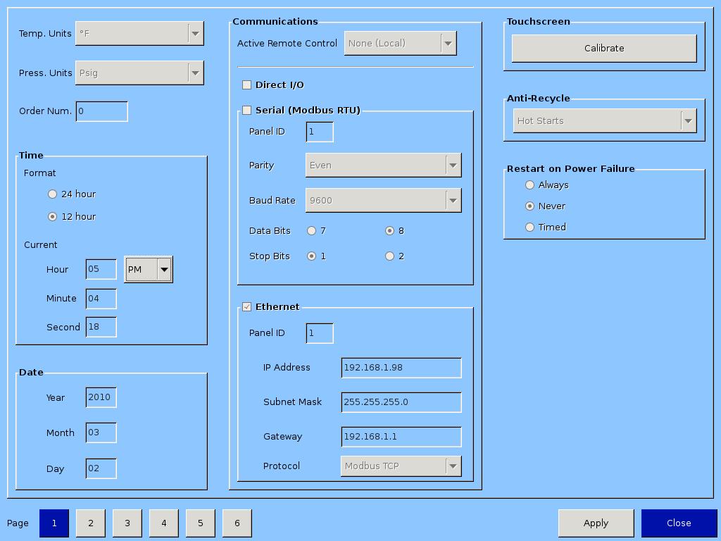
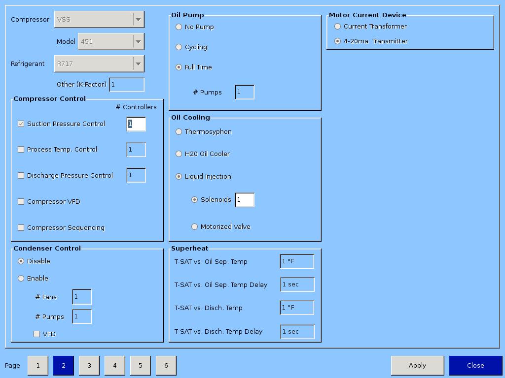
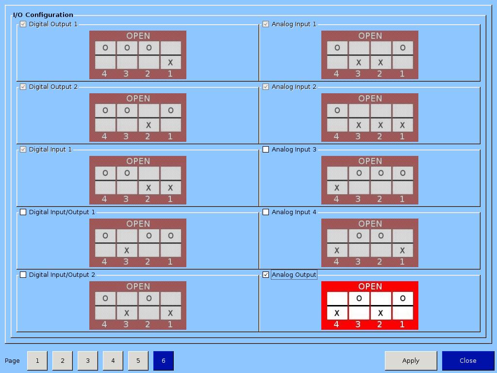
56 56 Configuration Screens
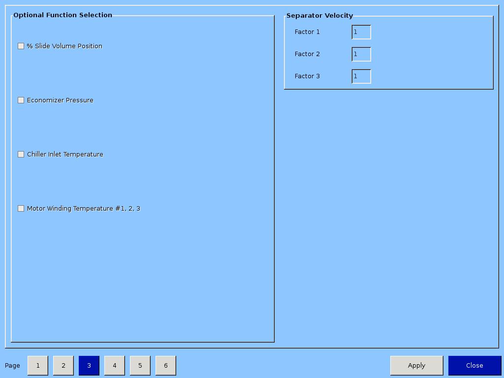
57 57

58 58

59 Maintenance Screen MALog on and check off each item as completed at the listed service interval. 59
60 Log In Screen This menu allows the operator to assign user accounts. The 20/20 will be shipped with a Level 3 operator and password pre-assigned to the installing contractor. He can then assign all lower level securities as needed. The procedure to assign access levels is to first press the logon button. The logon screen will appear with the preassigned Level 3 operator name visible. Highlight the name, then enter the password, then press the Apply button. Press the Manage Accounts tab to begin the process of entering another Operator name, and assigning password and user level of this additional user. Press the Add/Update button to add this user to the list, then press the Apply button before exiting the Logon screen to make this change permanent. Use the information below to determine the user level assignments. 60
61 Screen to Add Users 61
62 User Security Levels Level 1 View Only No password associated with this level Level 2 Operator Level Limited access Level 3 Full Access Supervisor Page User Level Note Event list Level 1 Input/output states Level 1 Trend chart Level 1 Slide calibration Level 3 Instrument calibration Level 3 Service options Level 3 Condenser control Level 2 Compressor sequencing Level 2 Compressor scheduling Level 2 Timer Setpoints Level 2 Constraints Level 4 Alarms trips Setpoints Level 2 Constraints Level 4 Delay Level 4 Compressor control Setpoints Level 2 Constraints Level 4 Configuration Page 1 Level 2 Order number needs to be level 4 Page 2 Level 2 Separator velocity - level 4 Page 3 Level 4 Page 4 Level 4 Page 5 Level 4 Page 6 Level 4 Language Level 1 Help Level 1 Maintenance Level 2 Data backup To save data Level 2 To upload date Level 4 Database may have level 4 parameters that would transfer Start compressor Level 2 Need a lock-out function Stop compressor Level 1 Volume slide move Level 4 62
63 Safety Failure Message Suction Pressure SP#1 Fail - This message will appear when the suction pressure falls below the safety setting of the Low Suction Pressure Trip Setpoint No.1. In addition, this message will appear when the suction pressure reading rises above 300 PSI, indicating an open transducer or bad analog channel. Suction Pressure SP#2 Fail - This message will appear when the suction pressure falls below the safety setting of the Low Suction Pressure Trip Setpoint No.2. In addition, this message will appear when the suction pressure reading rises above 300 PSI, indicating an open transducer. Discharge Pressure SP#1 Fail This message will appear when the discharge pressure exceeds the safety setting of the Hi Dsch Press Trip Setpoint No. 1. In addition, this message will appear when the discharge pressure reading falls below 30 Hg, indicating a shorted transducer. Discharge Pressure SP#2 Fail This message will appear when the discharge pressure exceeds the safety setting of the Hi Dsch Press Trip Setpoint No. 2. In addition, this message will appear when the discharge pressure reading falls below 30 Hg, indicating a shorted transducer. Suction Temp Fail This message will appear when the suction temperature falls below the safety setting of the Low Suction Temperature Trip setpoint. In addition, this message will appear when the suction temperature rises above 400 degrees, indicating an open RTD. Discharge Temp Fail This message will appear when the discharge temperature rises above the safety setting of the High Discharge Temperature Trip setpoint. In addition, this message will appear when the discharge temperature falls below -30 degrees, indicating a shorted RTD. Oil Separator Start Temp Fail This message will appear when the Oil Separator Temp is below the Low Oil Separator Start Temp Trip setpoint. In addition this message will appear after the Oil Separator Temp Safety Changeover timer times out and the Oil Separator temperature fails to rise above the Low Oil Separator Start Temp Reset after the compressor is started. Oil Separator Run Temp Fail This message will appear when the Oil Separator Temp is below the Low Oil Separator Run Temp Reset setpoint after the Oil Separator Temp Safety Changeover timer times out. Percent Capacity Fail This message will appear if the percent capacity reading exceeds 300% or goes below 15%. Percent Volume Fail This message will appear if the percent volume reading exceeds 300% or goes below 15%. Low Control Temperature Fail This message will appear when the Process Control Temperature falls below the safety setting of the Lo Control Temperature Trip Setpoint. In addition, this message will appear when the Process Control Temperature rises above 300 degrees F, indicating an open RTD. 63
64 Low Start Oil Pressure Fail This message will appear with the Prelub Oil Pressure (Manifold minus Discharge) has remained below the Prelub Oil Pressure Reset setpoint. The Prelub Oil Pressure must be above the Prelub Oil Pressure for a time period of the Minimum Compressor Prelub time. It will continue to try to do this for a time period of the Prelub Oil Pump Time Limit. When the Prelub Oil Pressure fails to achieve this, then the failure message will occur. Low Oil Pressure Fail This message will appear when the Running Oil Pressure (Manifold minussuction) has remained below the low Oil Pressure Reset setpoint when the Oil Pressure Bypass at Compressor Start timer times out. This message will also appear when the Runnning Oil Pressure falls below the Low Oil Pressure trip setpoint after the Oil Pressure Bypass at Compressor Start timer times out. Low Oil Injection Temp Fail This message will appear when the Oil Injection temperature falls below the Low Oil Injection Temperature trip setpoint. This message will also appear when the Oil Injection temperature fails to rise above the Low Oil Injection Temperature reset setpoint after the Low Oil Injection Temp Bypass timer times out. High Oil Injection Temp Fail This message will appear when the Oil Injection temperature rises above the High Oil Injection Temperature trip setpoint. Manifold Pressure Fail This message will appear with the manifold pressure rises above 300 PSI or falls below 30 Hg. Filter Inlet Pressure Fail This message will appear with the manifold pressure rises above 300 PSI or falls below 30 Hg. Start Filter Diff Press Fail This message will appear if the Filter Differential pressure rises above the High Fltr Diff Press Start setpoint before the Filter Differential Pressure Safety Changeover timer times out. Run Filter Diff Press Fail This message will appear if the Filter Differential pressure rises above the High Fltr Diff Press Run setpoint after the Filter Differential Pressure Safety Changeover timer times out. Maximum Amperage Fail This message will appear if the motor amperage rises above the Hi Motor Amps trip setpoint. Motor Starter Aux Contact Fail This message will appear if the Motor Auxiliary contact fails to close before the Compressor Starter Auxiliary Contact Bypass timer times out. Refer to wiring diagram. Auxiliary Safety#1 Input Fail This message will appear when power is removed from the input module that is designated as Auxiliary #1 Safety (please refer to your wiring diagram). Low Oil Separator Level Fail This message may appear when power is removed from the input module that is designated as Lo Separator Oil Level Trip (please refer to your wiring diagram). This safety has an associated delay. The associated delay timer is the Lo Oil Separator Level Bypass Timer. This safety will activate only after the oil level has been low after the timer times out. 64
65 Vission 20/20 Troubleshooting Guide Before applying power to the Vission 20/20 control panel, all wiring to the panel should be per the National Electrical Code (NEC). Specifically check for proper voltage and that the neutral is grounded at the source. An equipment ground should also be run to the panel. In the event of a problem with the Vilter Vission 20/20, the help screen, along with your electrical drawings will help determine the cause. PROBLEM and POSSIBLE SOLUTION 1. Vission 20/20 does not boot up, no lights light on any boards. a) Check to make sure 120VAC is run to circuit breaker CB1 located on the terminal strip. The neutral should be brought to any N terminal on the terminal strip. b) Check to insure circuit breaker CB1 s switch is flipped in the ON direction. c) Use a voltmeter to insure 120VAC is being applied to the power supply, located on the door. Check that 120 volts is present at the F1 fuse on the power supply, located on the front of the door. If all of the above are OK, the power supply may be bad. To test the power supply, check DC voltages at the power supply output. If proper voltages are not found at these test points, the power supply may be faulty. 2. Vission 20/20 appears to be booted, lights are lit on the boards, but no touchscreen display is evident. a) Remove power COMPLETELY from the Vission 20/20 and restart the controller. WARNING! The inverter board creates a high rms voltage to drive the backlight - it can exceed 1500VAC. Use extreme caution and insure that voltage has been removed from the board before physical inspection. Visually check cable connections located on the LCD inverter board. This board is located inside the door on the LCD touch screen back plane next to the single board computer. Physically inspect board to insure that all cable connectors are connected tightly to the board connectors. If these are inserted correctly, the problem could be a bad LCD inverter board or a component failure. 3. Vission 20/20 boots up but all data temperatures and pressures are zeroed and do not update. a) Check Analog board jumpers to insure proper node addresses are set up on all boards. Physically inspect power and communication jumper cables to insure they are inserted properly and completely. Two LEDs on all boards show the status of the communications for the board. LED1 is on when a command is received at the board from the single board computer (SBC), and LED2 is on when a response is sent from the board to the SBC. 65
66 Digital & Analog Boards DIGITAL OUT #1 (ADDRESS 1) ANALOG IN #1 (ADDRESS 6) DIGITAL OUT #2 (ADDRESS 2) ANALOG IN #2 (ADDRESS 7) DIGITAL IN (ADDRESS 3) ANALOG IN #3 (ADDRESS 8) DIGITAL I/O #1 (ADDRESS 4) ANALOG IN #4 (ADDRESS 9) DIGITAL I/O #2 (ADDRESS 5) ANALOG OUT (ADDRESS 10) The illustration above shows the position and type of the digital and analog input/output (I/O) boards. It is important to install the boards as shown in this illustration and configure them as show in the following illustrations. DIPSWITCHES Each board has a dipswitch which sets its communications address so that it can communicate with the CPU board. The dipswitch settings must be correct, or the I/O will not function. JUMPERS Jumpers are required on the analog boards to configure them for the type of sensors used. The jumper table for the analog board shows the optional jumper configurations for sensors other than the default Vilter standard. If a different sensor is to be used, the jumpers on the analog board need to be changed. In addition, the configuration for this sensor must be changed in the Instrument Calibration screen. The following illustrations show the Vilter default configurations for the Vission 20/20. 66
67 Digital Output #1 DIPSWITCH POSITION 4 Open (right) 3 Open (right) 2 Open (right) 1 Closed (left) 67
68 Digital Output #2 DIPSWITCH POSITION 4 Open (right) 3 Open (right) 2 Closed (left) 1 Open (right) 68
69 Digital Input DIPSWITCH POSITION 4 Open (right) 3 Open (right) 2 Closed (left) 1 Closed (left) 69
70 Digital Input/Output #1 DIPSWITCH POSITION 4 Open (right) 3 Closed (left) 2 Open (right) 1 Open (right) 70
71 Digital Input/Output #2 DIPSWITCH POSITION 4 Open (right) 3 Closed (left) 2 Open (right) 1 Closed (left) 71
72 Analog Input #1 DIPSWITCH POSITION 4 Open (right) 3 Closed (left) 2 Closed (left) 1 Open (right) JUMPER JP-1 JP-4 JP-7 JP-10 JP-13 JP-16 JP-25 JP-26 JP-35 POSITION ON ON ON ON ON ON POSITION-1 POSITION-1 ON 72
73 Analog Input #2 DIPSWITCH POSITION 4 Open (right) 3 Closed (left) 2 Closed (left) 1 Closed (left) JUMPER JP-16 JP-19 JP-22 JP-27 JP-28 JP-29 JP-30 JP-31 POSITION ON ON ON ON ON ON ON ON 73
74 Analog Input #3 DIPSWITCH POSITION 4 Closed (left) 3 Open (right) 2 Open (right) 1 Open (right) JUMPER JP-1 JP-25 JP-26 JP-28 JP-29 JP-30 JP-31 POSITION ON POSITION-2 POSITION-2 ON ON ON ON 74
 JUMPER JP-25 JP-26 JP-31 JP-32 JP-33 JP-34 POSITION POSITION-2 POSITION-2 ON ON ON ON")
75 Analog Input #4 DIPSWITCH POSITION 4 Closed (left) 3 Open (right) 2 Open (right) 1 Closed (left) JUMPER JP-25 JP-26 JP-31 JP-32 JP-33 JP-34 POSITION POSITION-2 POSITION-2 ON ON ON ON 75
76 Analog Output DIPSWITCH POSITION 4 Closed (left) 3 Open (right) 2 Closed (left) 1 Open (right) 76
77 Optional Analog Input Jumper Tables CHANNEL #1 SIGNAL JP-1 JP-2 JP-3 JP-27 JP-35 NOTES Analog Input 1-A 0-5 AMP OUT OUT OUT OUT IN Analog 1-A For Current Analog Input 1-B 0-5 Volt OUT OUT OUT OUT OUT Transformers 1-5 Volt OUT OUT OUT OUT OUT Only Volt OUT OUT IN OUT OUT 4-20 ma IN OUT OUT OUT OUT ICTD OUT IN OUT OUT OUT RTD OUT OUT OUT IN OUT CHANNEL #2 SIGNAL JP-4 JP-5 JP-6 JP-28 Analog Input Volt OUT OUT OUT OUT 1-5 Volt OUT OUT OUT OUT 0-10 Volt OUT OUT IN OUT 4-20 ma IN OUT OUT OUT ICTD OUT IN OUT OUT RTD OUT OUT OUT IN CHANNEL #3 SIGNAL JP-7 JP-8 JP-9 JP-29 Analog Input Volt OUT OUT OUT OUT 1-5 Volt OUT OUT OUT OUT 0-10 Volt OUT OUT IN OUT 4-20 ma IN OUT OUT OUT ICTD OUT IN OUT OUT RTD OUT OUT OUT IN CHANNEL #4 SIGNAL JP-10 JP-11 JP12 JP-30 Analog Input Volt OUT OUT OUT OUT 1-5 Volt OUT OUT OUT OUT 0-10 Volt OUT OUT IN OUT 4-20 ma IN OUT OUT OUT ICTD OUT IN OUT OUT RTD OUT OUT OUT IN CHANNEL #5 SIGNAL JP-13 JP-14 JP15 JP-31 Analog Input Volt OUT OUT OUT OUT 1-5 Volt OUT OUT OUT OUT 0-10 Volt OUT OUT IN OUT 4-20 ma IN OUT OUT OUT ICTD OUT IN OUT OUT RTD OUT OUT OUT IN 77
78 Optional Analog Input Jumper Tables CHANNEL #6 SIGNAL JP-16 JP-17 JP18 JP-32 Analog Input Volt OUT OUT OUT OUT 1-5 Volt OUT OUT OUT OUT 0-10 Volt OUT OUT IN OUT 4-20 ma IN OUT OUT OUT ICTD OUT IN OUT OUT RTD OUT OUT OUT IN CHANNEL #7 SIGNAL JP-19 JP-20 JP-21 JP-33 JP-25 Analog Input Volt OUT OUT OUT OUT Volt OUT OUT OUT OUT Volt OUT OUT IN OUT ma IN OUT OUT OUT 2 ICTD OUT IN OUT OUT 2 RTD OUT OUT OUT IN 2 ACTUATOR OUT OUT OUT OUT 1 POTENTIOMETER OUT OUT OUT OUT 3 CHANNEL #8 SIGNAL JP-22 JP-23 JP-24 JP-34 JP-26 Analog Input Volt OUT OUT OUT OUT Volt OUT OUT OUT OUT Volt OUT OUT IN OUT ma IN OUT OUT OUT 2 ICTD OUT IN OUT OUT 2 RTD OUT OUT OUT IN 2 ACTUATOR OUT OUT OUT OUT 1 POTENTIOMETER OUT OUT OUT OUT 3 78
79 79

80 EmersonClimate.com Vilter Manufacturing LLC P.O. Box 8904 Cudahy, WI P F Vilter Manufacturing LLC are trademarks of Emerson Electric Co. or one of its affi liated companies Emerson Climate Technoligies, Inc. All rights reserved. Printed in the USA SC Rev 2.00
Vission 20/20 micro-controller. Operation and service manual
 Vission 20/20 micro-controller Operation and service manual Section Title Table of Contents Section Number How To Use This Manual...TOC-8 Section 1 Operational Flow Charts Requirements to Start Compressor...1-1
Vission 20/20 micro-controller. Operation and service manual Version 2.6
 Vission 20/20 micro-controller Operation and service manual Version 2.6 Important Message READ CAREFULLY BEFORE OPERATING YOUR COMPRESSOR. The following instructions have been prepared to assist in operation
OPERATION MANUAL Variable Speed Pump Controller Dated: 06/04/2013 Pump Down Application. Document No.: LMSII_V100_OM Page 1 of 8 Model-V100 LMS II
 Document No.: LMSII_V100_OM Page 1 of 8 LMS II Document No.: LMSII_V100_OM Page 2 of 8 1. Operation: When the wet well level rises above the on level set point, the lead pump will start after an adjustable
VPN 35391RA_Rev. 02 August Price $ 40.00
 VPN 35391RA_Rev. 02 August 2007 Price $ 40.00 1 2 Important Note: Before applying power to the VANTAGE MicroController panel, all wiring to the panel should be per NEC. Specifically check for proper voltage
INSTRUCTIONS FOR INSTALLING AND OPERATING THE UNIVERSAL AUTOSYNC MODEL ASPSS DUAL COMPRESSOR SEQUENCER CONSOLE S/N 1638 AND ABOVE
 COMPRESSOR 1 EMERGENCY SHUTDOWN OFF POWER ON COMP LOADED COM PRESSOR OPERATING HOURS SYSTEM PRESSURE COMPRESSOR 2 EMERGENCY SHUTDOWN OFF POWER ON COMP LOADED COM PRESSOR OPERATING HOURS LEAD/LAG CONTROL
CURTIS TOLEDO. AF Series Compressors VS models with VFD WARNING
 AUGUST, 2004 REV.A CURTIS TOLEDO OPERATOR S MANUAL SUPPLEMENT AF Series Compressors VS models with VFD WARNING Personal injury and/or equipment damage will result by failing to pay attention to the vital
The function of this Dynamic Active Probe has divided into three preferences on the screen main Menus:
 1.0 Introduction: This probe is designed to provide an additional help to automotive technicians in trouble shooting of electrical circuits problems in the car. Apart from using the normal multi tester,
Application Engineering
 Application Engineering February, 2009 Copeland Digital Compressor Controller Introduction The Digital Compressor Controller is the electronics interface between the Copeland Scroll Digital Compressor
Models DP10 & DP20 Series Low Voltage Disconnects User s Manual Rev. 1.1 October 31, 2007
 B R A N D Models DP10 & DP20 Series Low Voltage Disconnects User s Manual Rev. 1.1 October 31, 2007 For Sales, Support and Service phone: 407-331-4793 fax: 407-331-4708 website: www.xenotronix.com email:
MATRIX LLC LEVEL CONTROL PANEL
 MATRIX LLC LEVEL CONTROL PANEL Installation Operation Maintenance Manual 1-26-09 REV-0.3 1 INDEX Introduction. 3 Product Configurations..... 4 I/O Descriptions. 8 Operation o Intercooler, Accumulator,
Application Guide Paragon TM Control Module (PCM) Slide Valve and Protection Control 10/25/2016 Rev 1. Carlyle Controller Part No.
 Slide Valve and Protection Control 10/25/2016 Rev 1. Carlyle Controller Part No.") Application Guide 575-012 Paragon TM Control Module (PCM) Slide Valve and Protection Control 10/25/2016 Rev 1 Carlyle Controller Part No. 2BSB000928 1 General Description The PCM is part of Paragon Compressor
Application Guide 575-012 Paragon TM Control Module (PCM) Slide Valve and Protection Control 10/25/2016 Rev 1 Carlyle Controller Part No. 2BSB000928 1 General Description The PCM is part of Paragon Compressor
Spartan Controls Millennium Compressor Control Panel Operating Philosophy
 Project: Stock Revision 1 Page 1 Spartan Controls Millennium Compressor Control Panel Operating Philosophy Location: Stock Customer references: Vendor: Vendor document: Spartan Controls Ltd. Operating
Application Engineering
 Application Engineering March 2011 Copeland Digital Compressor Controller Introduction The Digital Compressor Controller is the electronics interface between the Copeland Scroll Digital compressor or the
ICM325HN. Head Pressure Control with Optional Heat Pump Override. Installation, Operation & Application Guide
 ICM325HN Head Pressure Control with Optional Heat Pump Override Temperature sensitive control regulates head pressure Installation, Operation & Application Guide For more information on our complete range
SPC-PANEL Simplex, Single Phase Pump Control Panel
 Pump Installation and Service Manual SPC-PANEL Simplex, Single Phase Pump Control Panel Pump Controls for 2 HP Grinder Pumps NOTE! To the installer: Please make sure you provide this manual to the owner
Pump Installation and Service Manual HRS Hydromatic Retractable System
 Pump Installation and Service Manual HRS Hydromatic Retractable System NOTE! To the installer: Please make sure you provide this manual to the owner of the pumping equipment or to the responsible party
ICM 326HN/327HN Line Voltage Head Pressure Control Installation, Operation & Application Guide
 ICM 326HN/327HN Line Voltage Head Pressure Control With built-in transformer Optional heat pump override ICM326HN ICM327HN Installation, Operation & Application Guide For more information on our complete
Generator Start Control Module
 Generator Start Control Module Part# GSCM Rev C. Code Version: 5.13 ATKINSON ELECTRONICS, INC. 14 West Vine Street Murray, Utah 84107 Table of Contents Operations... 3 Specifications... 3 GSCM Wiring Diagram...
CHIP. Reverse Osmosis System Controller Documentation
 CHIP Reverse Osmosis System Controller Documentation Document Revised June, 2017. 2017 icontrols Technologies Inc icontrols Technologies Inc. 1821 Empire Industrial Court, Suite A Santa Rosa, CA 95403
MAXIGARD A2000 SPEED SWITCH. Introduction
 A107-05, Page 1 952-361-3026, INC. (Fax) 952-368-4129 327 LAKE HAZELTINE DRIVE, CHASKA, MN 55318 800-328-0738 MAXIGARD A2000 SPEED SWITCH Introduction The Maxigard A2000 Speed Switch is designed to monitor
Supersedes CL2 (512) Form CL2 (615) STARTUP CHECKLIST PHONE: CUSTOMER ORDER NO: JCI TEL NO: JCI ORDER NO: JCI CONTRACT NO:
 Form CL2 (615) STARTUP CHECKLIST PHONE: CUSTOMER ORDER NO: JCI TEL NO: JCI ORDER NO: JCI CONTRACT NO:") YMC 2 - MOD A STARTUP CHECKLIST Supersedes 160.78-CL2 (512) Form 160.78-CL2 (615) STARTUP CHECKLIST CUSTOMER: JOB NAME: ADDRESS: LOCATION: PHONE: CUSTOMER ORDER NO: JCI TEL NO: JCI ORDER NO: JCI CONTRACT
YMC 2 - MOD A STARTUP CHECKLIST Supersedes 160.78-CL2 (512) Form 160.78-CL2 (615) STARTUP CHECKLIST CUSTOMER: JOB NAME: ADDRESS: LOCATION: PHONE: CUSTOMER ORDER NO: JCI TEL NO: JCI ORDER NO: JCI CONTRACT
Installation, Operation, and Maintenance Manual CEMLINE CORPORATION
 $5.00 Installation, Operation, and Maintenance Manual CEMLINE CORPORATION CEM-TROL II Solid State Control Module and Electronic Control Valves P. O. Box 55, Cheswick, PA, 15024 Phone: (724) 274-5430 FAX
UniTorq UTQ Quarter-Turn Actuator Installation and Operation Manual
 UniTorq UTQ 1.5 6.4 Quarter-Turn Actuator Installation and Operation Manual Thank you for purchasing our UTQ 1.5-6.0 Electric Actuators Before installation or operation of the actuator carefully review
ECLIPSE Laundry Dispenser Controller
 ECLIPSE Laundry Dispenser Controller Reference Manual Programming and Operation Online and downloadable Product Manuals and Quick Start Guides are available at www.hydrosystemsco.com Please check online
R & D SPECIALTIES ROTROL I USER'S MANUAL
 R & D SPECIALTIES ROTROL I USER'S MANUAL TABLE OF CONTENTS INTRODUCTION...2 SPECIFICATIONS...2 CONTROLS AND INDICATORS...3 TIME DELAYS...4 INSTALLATION...5 SYSTEM OPERATION...9 TROUBLESHOOTING...13 OPTIONAL
P445 Series Electronic Lube Oil Control
 FANs 125, 121 s Section P Product/Technical Bulletin P445 Issue Date 0100 P445 Series Electronic Lube Oil The P445 Series Electronic Lube Oil is designed for use on refrigeration compressors equipped with
INSTRUCTION MANUAL INSTALLATION, OPERATION, AND MAINTENANCE ACTUATOR MANIFOLD
 INSTRUCTION MANUAL INSTALLATION, OPERATION, AND MAINTENANCE B-3724M ACTUATOR MANIFOLD MIDLAND MANUFACTURING CORP. 7733 Gross Point Road Skokie, Illinois 60077 Phone (847) 677-0333 FAX (847) 677-0138 WEBSITE
HYGRODYNAMICS DEW POINT MONITOR MODEL 8092P 8092P-230VAC TABLE OF CONTENTS DIAGRAMS
 HYGRODYNAMICS DEW POINT MONITOR MODEL 8092P 8092P-230VAC TABLE OF CONTENTS SPECIFICATIONS 1 PRINCIPLE OF OPERATION 1 INSTALLATION 2 Choosing a Sampling Location 2 Mounting the Enclosure 2 Remote Alarm
MODEL 422 Submersible Pump Controller
 MODEL 422 Submersible Pump Controller Monitors True Motor Power (volts x current x power factor) Detects Motor Overload or Underload Operates on 120 or 240VAC, Single-phase or 3-phase Built-in Trip and
A problem with the motor windings. A phase loss on mains terminals L1, L2, or L3 during run mode. Parameter 2-3 Current Imbalance Delay.
 10 Troubleshooting When a protection condition is detected, the VLT Soft Starter MCD 500 writes this condition to the event log and may also trip or issue a warning. The soft starter response depends on
Tracer VMA with AutoReg
 Tracer with AutoReg Flowmeter with Automatic Flow Regulation Operating Instructions RoHS Compliant General The Tracer Flowmeter with AutoReg provides: Analog Flow Output (Selectable 0 to 3.5V, 0 to 5V
AD-7. Instruction Manual. Thermal Indicating Ammeter HD ELECTRIC COMPANY 1475 LAKESIDE DRIVE WAUKEGAN, ILLINOIS U.S.A.
 CONTROLS & SYSTEM MEASUREMENT AD-7 Thermal Indicating Ammeter Instruction Manual HD ELECTRIC COMPANY 1475 LAKESIDE DRIVE WAUKEGAN, ILLINOIS 60085 U.S.A. PHONE 847.473.4980 FAX 847.473.4981 website: www.hdelectriccompany.com
MD10. Engine Controller. Installation and User Manual for the MD10 Engine Controller. Full Version
 MD10 Engine Controller Installation and User Manual for the MD10 Engine Controller. Full Version File: MartinMD10rev1.4.doc May 16, 2002 2 READ MANUAL BEFORE INSTALLING UNIT Receipt of shipment and warranty
FRICK QUANTUM HD COMPRESSOR CONTROL PANEL
 Operation Form 090.040-O (AUG 2014) File: SERVICE MANUAL - Section 90 Replaces: 090.040-O (JUNE 2013) Dist: 3, 3a, 3b, 3c FRICK QUANTUM HD COMPRESSOR CONTROL PANEL Version 10.16 CURRENT DESIGN AUGUST 2014
Reciprocating Equipment Manager Operations Manual AIR / FUEL RATIO AND GOVERNOR CONTROL
 REMVue Reciprocating Equipment Manager Operations Manual AIR / FUEL RATIO AND GOVERNOR CONTROL REMVue 500/AS OPERATIONS MANUAL Version 3 April 16, 2007 DISCLAIMER This document is designed to provide information
SECTION MOTORS AND VARIABLE FREQUENCY DRIVES
 PART 1 GENERAL 1.1 RELATED DOCUMENTS A. Related Sections: 1. Section 15050 - Basic Mechanical Requirements. 2. Section 15051 - Motors. 3. Section 15185 - Hydronic Pumps. 4. Section 15625 - Centrifugal
Installation, Operation, and Maintenance Manual CEMLINE CORPORATION
 $5.00 Installation, Operation, and Maintenance Manual CEMLINE CORPORATION CEM-TROL Solid State Control Module and Electronic Control Valves P. O. Box 55, Cheswick, PA, 15024 Phone: (724) 274-5430 FAX (724)
Advantage-D. Operating Instructions and Maintenance Manual. Central Vacuum Systems (Expandable/Modular Models) (Ver.
 (Ver.") Advantage-D Series 3 Central Vacuum Systems (Expandable/Modular Models) (Ver. 8/05) Operating Instructions and Maintenance Manual DESCRIPTION The Becker Advantage-D and Advantage-L central vacuum systems
Advantage-D Series 3 Central Vacuum Systems (Expandable/Modular Models) (Ver. 8/05) Operating Instructions and Maintenance Manual DESCRIPTION The Becker Advantage-D and Advantage-L central vacuum systems
AUTOMATIC AND MANUAL TRANSMISSION MODELS* *MUST USE M SERIES REMOTE STARTER!
 REV.2011.7.22 80 SERIES Advanced Remote Starters & Vehicle Security Systems AUTOMATIC AND MANUAL TRANSMISSION MODELS* *MUST USE M SERIES REMOTE STARTER! WARING: NEVER USE AN AUTOMATIC TRANSMISSION STARTER
NECO Pumping Systems
 INSTALLATION OPERATION & MAINTENANCE INSTRUCTIONS For Your NECO Pumping Systems PACKAGED CIRCULATING SYSTEM THIS COMPLETELY ASSEMBLED, TESTED, PACKAGED CIRCULATING SYSTEM IS OF THE HIGHEST QUALITY AND
MANUAL Model: PT 12/24-60 Solar Converters Inc. - Rev. F
 1.0 Specification MANUAL Model: PT 12/24-60 Solar Converters Inc. - Rev. F Note: This unit is a Multi - Voltage unit with adjustable input panel and output battery adjustment. Please review the section
University of Houston Master Construction Specifications Insert Project Name SECTION ELECTRONIC VARIABLE SPEED DRIVES PART 1 - GENERAL
 SECTION 23 04 10 ELECTRONIC VARIABLE SPEED DRIVES PART 1 - GENERAL 1.1 RELATED DOCUMENTS: A. The Conditions of the Contract and applicable requirements of Division 1, "General Requirements", and Section
GENERATOR START CONTROL MODULE
 GENERATOR START CONTROL MODULE Operating and Installation Instructions Many automatic control features: Automatic starting, load transfer & shutdown of gas/diesel generators, especially for off-grid uses
Manual Transfer Switch
 Manual Transfer Switch Instruction Manual 30 1200 Amp 2, 3 & 4 Pole Page 1 WARNING Before Installation READ THIS MANUAL carefully to learn how to properly install, operate and maintain this unit. Personal
TMD90A Dual Input Digital Thermometer
 TMD90A Dual Input Digital Thermometer User Manual For detailed specifications and ordering info go to www.testequipmentdepot.com TMD90A Dual Input Thermometer Contents Safety Information 2 Symbols Used
TW W-40 FLAG FRAME VARIABLE SPEED BOOSTER SYSTEM
 TW1000-20W-40 FLAG FRAME VARIABLE SPEED BOOSTER SYSTEM TW1000-20W-40 FLAG FRAME The TW1000-20W-40 Flag Frame Booster System is equipped with a centrifugal pump regulated by a variable frequency drive that
AD-7 THERMAL INDICATING AMMETER
 AD-7 THERMAL INDICATING AMMETER a nd ACCESSORIES Operating & Instruction Manual HD ELECTRIC COMPANY 1 4 7 5 L A K E S I D E D R I V E W A U K E G A N, I L L I N O I S 6 0 0 8 5 U. S. A. P H O N E 8 4 7.
Generator Start Control Module
 Generator Start Control Module Part# GSCM-mini-i ATKINSON ELECTRONICS, INC. 14 West Vine Street Murray, Utah 84107 Contact cbdsales@atkinsonel.com for the proper hookup diagram. Please include the generator
ACCESSORY KIT INSTALLATION INSTRUCTIONS
 ACCESSORY KIT INSTALLATION INSTRUCTIONS Low Ambient Accessory For Air Cooled Split-System Air Conditioners YD360/480/600, YJ-30/-40/-50 and J30/40/50 YD Models 642546-UAI-A-080 GENERAL Standard operation
INSTALLATION/OPERATING INSTRUCTIONS TSC
 INSTALLATION/OPERATING INSTRUCTIONS TSC Two-Stage Set Point Control with External Activation Two-Stage Heating (Rotation Included) Two-Stage Cooling (Rotation Included) Change-Over Control (Heat/Cool)
Temperature Controller. TC5+2V4SA Plus USER'S MANUAL
 Temperature Controller TC5+2V4SA Plus USER'S MANUAL NOTICE Every effort has been made to ensure that this manual is complete, accurate and up-to-date. The information contained in it is however subject
6. Document tasks performed during visit and report any observations to the appropriate
 Chiller Annual Maintenance RFP Attachment B Services Required Tasking: Vibration Analysis 1. All work shall be performed in accordance with safety policies 2. Check with appropriate customer representative
Generator Start Control Module
 Generator Start Control Module Part# GSCM-mini-o ATKINSON ELECTRONICS, INC. 14 West Vine Street Murray, Utah 84107 Contact cbdsales@atkinsonel.com for the proper hookup diagram. Please include the generator
Application Engineering Europe
 Date of last update: Feb-12 Ref: D7.8.4/0112-0212/E Application Engineering Europe CORESENSE DIAGNOSTICS FOR STREAM REFRIGERATION COMPRESSORS 1/17 1 Introduction CoreSense is an ingredient brand name for
HP21 SERVICE SUPPLEMENT UNIT INFORMATION. TSC6 Two-Speed Control
 SERVICE UNIT INFORMATION SUPPLEMENT HP21 Corp. 9426 L10 Litho U.S.A. All HP21-4 and -5 units (single and three phase) are equipped with a TSC6 two-speed control. The TSC6 (A14) two-speed control contains
Updated: October 2012
 T: (630) 794-5100 EMERGENCY POWER FUEL SYSTEMS Earthsafe Systems, Inc. 7320 S. Madison Willowbrook, IL 60527 F: (630) 794-5106 info@earthsafe.com www.earthsafe.com Updated: October 2012 The information
Duplex Booster System Instruction Manual
 Duplex Booster System Instruction Manual ISO 9001 Certified Walrus America Inc Congratulations on your purchase of Walrus IC Series Inverter Control System. Please read all instructions carefully before
OWNER S MANUAL AND INSTALLATION INSTRUCTIONS
 EmerGen Switch Manual Transfer Switch OWNER S MANUAL AND INSTALLATION INSTRUCTIONS For A Series Models 6-5001, 6-7501, 10-7501, 10-12K1 PLEASE READ THIS MANUAL IN ITS ENTIRETY BEFORE INSTALLING AND/OR
ROC-2. icontrols. Reverse Osmosis System Controller Documentation
 ROC-2 Reverse Osmosis Controller Documentation Document Revised February 23, 2009. i controls inc. 15916 SE 41st Place Bellevue, WA 98006 ph (425) 577-8851 www..net Welcome. Thank you for purchasing an
Combined Ventilation Controller RVWS-T-113HA
 Combined Ventilation Controller RVWS-T-113HA 5-stage Control for Power/Natural Applications 1 variable speed stage, 1 curtain winch stage, 1 fixed speed ventilation stage, 1 thermo/mister cycle stage and
Operators Manual. Recirculating Chiller /06/08
 Operators Manual Recirculating Chiller 110-197 11/06/08 Table of Contents Section 1. General Information 1.1 Warranty 1.2 Unpacking 1.3 Package Contents 1.4 Description of the Recirculating Chiller 1.5
INSTALLATION/OPERATING INSTRUCTIONS MCP
 INSTALLATION/OPERATING INSTRUCTIONS MCP Modulating Digital Set Point Control with Boiler Output and External Activation Temperature Range -30 to 250 F (-35 to 120 C) Pressure Ranges 0-30, 0-100, 0-200PSI
HGM6410/6420 AUTOMATIC GENERATOR MODULE WITH J1939 INTERFACE SOFTWARE MANUAL
 HGM6410/6420 AUTOMATIC GENERATOR MODULE WITH J1939 INTERFACE SOFTWARE MANUAL SMARTGEN ELECTRONICS Smartgen Electronic Equipment Co., Ltd No.12 Dongqing Street Zhengzhou Henan Province P.R.China Tel : (0086)-371-67992951
PORT-A-WEIGH CRANE SCALES
 MSI4260 PORT-A-WEIGH CRANE SCALES User Guide Quality Industrial Weighing and Force Measurement Equipment Measurement Systems International Page 2 MSI-4260 Port-A-Weigh User Guide TABLE OF CONTENTS Introduction...
OPERATING INSTRUCTIONS PLEASE READ CAREFULLY
 OPERATING INSTRUCTIONS PLEASE READ CAREFULLY 925-0330 Rev 0 0416 TABLE OF CONTENTS SAFETY SUMMARY... 3 SPECIFICATIONS... 4 1.0 INTRODUCTION/DESCRIPTION.... 5 2.0 LOCATION AND MOUNTING... 5 3.0 CONNECTIONS
II DISTRIBUTION & SUBSTATION TYPE C
 CapCheckIII DISTRIBUTION & SUBSTATION TYPE Ca p a c i t o r C h e c ke r Operating & Instruction Manual 1475 Lakeside Drive Waukegan, Illinois 60085 U.S.A. 847.473.4980 f a x 8 4 7. 4 7 3. 4 9 8 1 w e
EchoPod. UG06 & UG12 Series Quick Start Flowline, Inc. All Rights Reserved Made in USA. Ultrasonic Liquid Level Transmitter
 EchoPod Ultrasonic Liquid Level Transmitter UG06 & UG12 Series Quick Start 2017 Flowline, Inc. All Rights Reserved Made in USA Flowline, Inc. 10500 Humbolt Street, Los Alamitos, CA 90720 p 562.598.3015
Model C230 Pump Controller
 MANUAL Model C230 Earthsafe Systems, Inc. 7553 S. Madison Willowbrook, IL 60527 T: (630) 794-5100 F: (630) 794-5106 info@earthsafe.com www.earthsafe.com March 1, 2010 The information contained herein is
OPERATING INSTRUCTIONS AND PARTS LIST BRIDGE DRIVE GEAR CASE
 OPERATING INSTRUCTIONS AND PARTS LIST BRIDGE DRIVE GEAR CASE GENERAL Units are intended to be used within 30 days after receipt. If they are to be stored for a longer period of time, contact the factory
Model LA 4400 Time Delay OFF Controller
 ISIMET LA Series Model LA 4400 Time Delay OFF Controller Installation, Operation and Maintenance Manual Application: The Time Delay OFF Controller with integral 24-hr. programmable time clock operates
INSTRUCTIONS FOR INSTALLING AND OPERATING THE UNIVERSAL AUTODUAL MODEL ADSE-2 DUAL COMPRESSOR SEQUENCER (firmware ver 1.02
 COMP RES SOR OPE RATING H OURS COMPR ESS OR OPE RATING H OURS COMPRESSOR 1 E ME RGENCY S HUTDOW N OFF P OW ER ON COMP LOADED LEAD/LAG CONTROL AUTO ON S YSTEM PRE SSU RE COMPRESSOR 2 E MERGE NCY S HUTDOW
CLA-VAL e-drive-34. User Manual. Motorised Pilots. CLA-VAL Europe LIN072UE - 04/16
 User Manual CLA-VAL Europe www.cla-val.ch cla-val@cla-val.ch 1 - LIN072UE - 04/16 Table of Contents 1 Introduction... 3 1.1 Precautions Before Starting... 3 1.2 Troubleshooting... 3 1.3 General Disclaimer...
Model 20 Constant Speed Blender : 115 Volt : 230 Volt. Instruction Manual. Updated 11/14/2017 Ver. 4.0
 Model 20 Constant Speed Blender 120-65: 115 Volt 120-65-1: 230 Volt Instruction Manual Updated 11/14/2017 Ver. 4.0 OFI Testing Equipment, Inc. 11302 Steeplecrest Dr. Houston, Texas 77065 U.S.A. Tele: 832.320.7300
EDG6000 Electronic Digital Governor
 INTRODUCTION GAC s digital governor is designed to regulate engine speed on diesel and gaseous fueled engines. When paired with a GAC actuator the EDG is a suitable upgrade for any mechanical governor
A/C PRESSURE MONITOR INSTALLATION INSTRUCTIONS SYSTEM OPERATION GREEN INDICATOR LIGHT
 A/C PRESSURE MONITOR INSTALLATION INSTRUCTIONS Do not attempt to clean or inspect anything while the engine is running. Cleaning and inspection must be done by a certified mechanic. All A/C service must
UD SERIES COMPRESSORS
 UD SERIES COMPRESSORS INDUSTRIAL AIR COMPRESSOR 40-400 HP UPDRAFT MODELS Electric Motor - 460/575/3/60 standard (208/230/3/60 optional on most models) Motor Starter - 460 volt, full voltage magnetic starter
Electrically Released Motor Brake Module for EM-MBFB and EUM-MBFB Size 50, 100, 180
 Electrically Released Motor Brake Module for EM-MBFB and EUM-MBFB Size 50, 100, 180 P-273-8-WE 819-0531 Installation Instructions Vented Enclosed Version Optional Warner Electric s MBFB series of Electrically
TW G-40 FLAG FRAME VARIABLE SPEED BOOSTER PUMP SYSTEM
 TW1000-75G-40 FLAG FRAME VARIABLE SPEED BOOSTER PUMP SYSTEM The TW1000-75G-40 Flag Frame Booster System is equipped with a centrifugal pump regulated by a variable frequency drive that controls the pump
Model NTX7 Series Automatic Battery Charger User s Manual Rev. 1.0 October 17, 2006
 B R A N D Model NTX7 Series Automatic Battery Charger User s Manual Rev. 1.0 October 17, 2006 For Sales, Support and Service phone: 407-331-4793 fax: 407-331-4708 website: www.xenotronix.com email: information@xenotronix.com
TECHNICAL PAPER 1002 FT. WORTH, TEXAS REPORT X ORDER
 I. REFERENCE: 1 30 [1] Snow Engineering Co. Drawing 80504 Sheet 21, Hydraulic Schematic [2] Snow Engineering Co. Drawing 60445, Sheet 21 Control Logic Flow Chart [3] Snow Engineering Co. Drawing 80577,
- Data Brochure D 156. Difference Setpoint Control 156. Item 06/10
 - Data Brochure Difference Setpoint Control 156 D 156 06/10 The Difference Setpoint Control 156 is designed to operate an on/off pump to transfer heat from a heat source to a storage tank. The control
Axpert-CSS AMTECH DRIVES Axpert-CSS Amtech
 The Axpert-CSS is a range of Combination Soft Starter panels offered by AMTECH DRIVES. We also offer the module unit as an individual product, named as Axpert-Opti torque Soft Starter. This is only the
Installation & Operation Manual. Electrak 10 Series / Electromechanical Linear Actuator
 www..com Installation & Operation Manual Electrak 10 Series / Electromechanical Linear Actuator INTRODUCTION Thomson has many years of experience designing and manufacturing linear actuators for a wide
Factory Packaged Controls. OE (AAON Part No. V12090) MODGAS-X Controller Field Technical Guide
 MODGAS-X Controller Field Technical Guide") Factory Packaged Controls OE377-26-00058 (AAON Part No. V12090) MODGAS-X Controller Table of Contents GENERAL INFORMATION... 3 Overview...3 Features...3 INSTALLATION & WIRING... 4 Supply Air Temperature
Factory Packaged Controls OE377-26-00058 (AAON Part No. V12090) MODGAS-X Controller Table of Contents GENERAL INFORMATION... 3 Overview...3 Features...3 INSTALLATION & WIRING... 4 Supply Air Temperature
Z-Tech Severe Chemical Service Valves We Put Control Where You Need It.
 Z-Tech Severe Chemical Service Valves We Put Control Where You Need It. Z-Tech Series Valves TABLE OF CONTENTS Ball Valves ZT 4 Series: Three Piece Flanged Ball Valve... -3 Pneumatic Actuators and Accessories...
CORESENSE DIAGNOSTICS FOR STREAM REFRIGERATION COMPRESSORS
 Date of last update: Apr-15 Ref: D7.8.4/0112-0415/E Application Engineering Europe CORESENSE DIAGNOSTICS FOR STREAM REFRIGERATION COMPRESSORS CoreSense Diagnostics for Stream Refrigeration Compressors...
RETROFIT CONVERSION TO THE VILTER SINGLE SCREW INSTALLATION INSTRUCTIONS. Contents
 Form 090.040-I02 (JAN 2018) INSTALLATION File: SERVICE MANUAL - Section 90 Replaces: 090.040-I02 (JUL 2017) Dist: 3, 3a, 3b, 3c RETROFIT CONVERSION TO THE FRICK QUANTUM HD CONTROL VILTER SINGLE SCREW Contents
Model HPX60 Series Automatic Battery Charger User s Manual Rev. 1.0 October 17, 2006
 B R A N D Model HPX60 Series Automatic Battery Charger User s Manual Rev. 1.0 October 17, 2006 For Sales, Support and Service phone: 407-331-4793 fax: 407-331-4708 website: www.xenotronix.com email: information@xenotronix.com
GC-1. Roof and Gutter De-Icing Control Installation and Operating Instructions FOR EXTERIOR INSTALLATION ONLY
 GC-1 Roof and Gutter De-Icing Control Installation and Operating Instructions FOR EXTERIOR INSTALLATION ONLY GENERAL INFORMATION The GC-1 heating cable controller has been designed and manufactured for
PCT-3001 plus. Display LCD
 PCT3 plus DIGITAL PRESSURE CONTROLLER FOR COOLING PLANTS DESCRIPTION Pressure controller for refrigeration systems capable to control suction (compressors) and discharge (fans) pressures. It is possible
SPC Series. Digital Scale. Operation Manual
 SPC Series Digital Scale Operation Manual Revision 1.0 August 17, 2000 ! WARNING Use only the AC adapter which comes with the scale. Other adapters may cause damage. Internal service to this product should
Applications. Compressor-Features The Vilter Advantages. LNG Boil Off Gas Gathering BIO - Gas Digester CO 2 Nitrogen Hydrogen Refrigerant
 Parallex TM Slide System - It s the key to part load efficiencies far superior to twin screw compressors. Capacity and volume slides move independently of each other based on load, eliminating over or
Start-Up, Operation and Service Instructions
 Article I. Krueger Proportional LineaHeat W/ Discharge Temperature Start-Up, Operation and Service Instructions SAFETY NOTE Air-handling equipment will provide safe and reliable service when operated within
DPD72001, DPD Unipolar Step Motor Driver. User s Guide E. Landon Drive Anaheim, CA
 DPD72001, DPD72002 Unipolar Step Motor Driver User s Guide A N A H E I M A U T O M A T I O N 4985 E. Landon Drive Anaheim, CA 92807 e-mail: info@anaheimautomation.com (714) 992-6990 fax: (714) 992-0471
Tracer VM with User Interface
 Tracer with User Interface Flowmeter with FCI (Fluid Characteristic Indication) Operating Instructions General The Tracer Flowmeter provides: 0 to 5V or 0 to 10V Selectable Analog Flow Output 0 to 5V or
SRC. An Outdoor Reset Control for Sub-Atmosphere Steam Systems OUTDOOR TEMPERATURE
 SRC STEAM RESET CONTROL An Outdoor Reset Control for Sub-Atmosphere Steam Systems Heat-Timer s theory of steam reset heating is as follows: Pulse the valve open to a limited valve position, very slowly
Temperature Controller OVATION 214 User's Guide
 Temperature Controller User's Guide Read this guide carefully before using the controller. 890-00045 rev.00 TABLE OF CONTENTS Page TABLE OF CONTENTS... 2 PRECAUTIONS... 3 FEATURES... 4 LOCATION OF THE
User Manual. T6 Tachometer. Online: Telephone: P.O. Box St. Petersburg, Florida 33736
 User Manual T6 Tachometer Online: www.phareselectronics.com Telephone: 727-623-0894 P.O. Box 67251 St. Petersburg, Florida 33736 Table of Contents Overview... 1 Description... 1 Wiring... 1 T6 Tachometer
HA/HAB Fiberglass Wall Mount Ventilators
 HA/HAB Fiberglass Wall Mount Ventilators INSTALLATION, OPERATION & MAINTENANCE MANUAL IM-3100 August 2015 Throughout this manual, there are a number of HAZARD S that must be read and adhered to in order