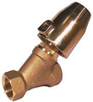
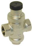
Mounting and Operating Manual Non-Return valves Swing-Check valves
|
|
|
- Lauren Anderson
- 6 years ago
- Views:
Transcription


1 Mounting and Operating Manual Non-Return valves Swing-Check valves END-Armaturen GmbH & Co. KG Oberbecksener Str. 78 D Bad Oeynhausen Telefon (05731) Telefax (05731)
2 Impressum by END-Armaturen GmbH & Co. KG All rights reserved. END-Armaturen GmbH & Co. KG claims copyright over this documentation. This documentation may neither be altered, expanded, reproduced nor passed to third parties without the written agreement of END-Armaturen GmbH & Co. KG. This restriction also applies to the corresponding drawings. END-Armaturen GmbH & Co. KG has the right to change parts of the non-return valves / swing check valves at any time without prior or direct notice to the client. The contents of this publication are subject to change without notice. This publication has been written with great care. However, END-Armaturen GmbH & Co.KG cannot be held responsible, either for any errors occuring in this publication or for their consequences. The products are specified by the statements in this documentation; no assurance of the properties is given. END-Armaturen GmbH & Co. KG Oberbecksener Straße 78 D Bad Oeynhausen Telefon: / Telefax: / Internet: post@end.de Edition: 03/ /2015
3 Contents Contents 1 Foreword 4 2 General Advice Validity Inward monitoring Complaints Guarantee Symbols and their signification 6 3 Safety Advice Personal advice Safety advices for mounting Safety advice for maintaining / repairing Device safety 9 4 Name-plate 10 5 Non-Return valves, Swing-Check valves General Corresponding use Operation Mounting / Disassemble Mounting with threaded connection Mounting with welded connection Disassemble of the bonnet and the inner parts Welding the body between pipes Mounting of the bonnet and the inner parts Mounting of the valve with flanged connection Maintenance 15 03/
4 Foreword 1 Foreword Dear customer, Dear assembler / user, these operation and installation manuals are intended to give you the knowledge, which is necessary for you to be able to carry out the mounting and adjustment of the non-return valves / swing-check valves rapidly and correctly. Please read these instructions carefully and pay particular attention to the advice and warning notes. Only instructed and qualified mechanician should mount, adjust or maintain the non-return valves / swing-check valves. If you have any questions in relation to the non-return valves / swing-check valves we shall be pleased to answer them. The telephone number will be found on the inside cover of these operation and installation manual. Yours END-Armaturen GmbH & Co. KG /2015
5 General Advice 2 General Advice 2.1 Validity This mounting and installation manual is valid for the standard versions of the non-return valves / swing-check valves and their variants. 2.2 Inward monitoring Please check directly after delivery the non-return valves /swing-check valves for any transport damages and deficiencies and with reference to the accompanying delivery note the number of parts. Do not leave any parts in the package. 2.3 Complaints Claims for replacement or goods which relate to transport damage can only be considered valid if the delivery company is notified without delay. In case of returns (because of transport damage / repairs), please make a damage protocol and send the parts back to the manufacturer, if possible in the original packaging. In case of a return, please mention the following: Name and address of the consignee Stock-/ ordering-/ article-number Description of the defect 2.4 Warranty For our non-return valves / swing-check valves we give a guarantee period in accordance with the sales contract. The end of the normal duration of life of the wearing parts represents no defect. The warranty and guarantee rules of END-Armaturen GmbH & Co. KG are applicable. 03/
6 Symbols and their signification 2.5 Symbols and their signification Paragraphs which are identified with this symbol contain very important advices; this also includes advices for averting health risks. Observe these paragraphs without fail! Paragraphs which are identified with this symbol contain very important advices, this also includes how to avoid damage to property. Observe these paragraphs without fail! This symbol indicates paragraphs which contain comments / advices or tips. This spanner identifies the description of actions which you should carry out /2015
7 Safety Advice 3 Safety Advice Depending on the technical circumstances and the time under and at which the non-return valves / swing-check valves are mounted, adjusted and commissioned, you must take into account particular safety aspects in each case! If, for example, a non-return valve / swing-check valve works a slide in an operational chemical plant, the potential hazards of commissioning have another dimension from that when this is only being carried out for test purposes an a dry part of the plant in the assembly room! Since we do not know the circumstances at the time of the mounting/adjustment/commissioning, you may find advices on hazards in the following descriptions which are not relevant to you. Please observe (only) the advices which applies to your situation! 3.1 Personal advice Safety advices for mounting We wish to point out expressly that the mounting, adjusting and at accessories the pneumatical and electrical installation of the butterfly valves must be carried out by trained specialist personnel having mechanical, pneumatical and electrical knowledge! Secure that the machine / plant come up to the Machinery Directive after the mounting and installing of the ball valves. Switch off all the devices / machines / plant affected by mounting or repair. If appropriate, isolate the devices / machines / plant from the mains. Check (for example in chemical plants) whether the switching off of devices / machines / plant will cause potential danger. If appropriate, in the event of a fault in the butterfly valve (in a plant which is in operation) inform the shift foreman / safety engineer or the works manager without delay about the fault, in order, for example, to avoid an outflow / overflow of chemicals or the discharge of gases in good time by means of suitable measures! Before mounting or repairing, remove the pressure from pneumatic / hydraulic devices / machines / plant. If necessary, set up warning signs in order to prevent the inadvertent starting up of the devices / machines / plant. Observe the respective relevant professional safety and accident prevention regulations when carrying out the mounting / repair work. Check the correct functioning of the safety equipment (for example the emergency push off buttons/ safety valves, etc)! Safety advice for adjustment / starting As a result of the starting of the non-return valves / swing-check valves the flow of gases, steam, liquids, etc. may be enabled or interrupted! Satisfy yourself that, as a result of the starting or the test adjustment no potential hazards will be produced for the personnel or the environment! 03/
8 Safety Advice If necessary, set up warning signs in order to prevent the inadvertent starting up or shutting down of the device / machine / plant.! By ending the adjustment check the correct function and should the occasion arise the position of the non-return valve / swing-check valve. Check the function of the limit switches (option)! Check, whether the armature will be closed totally, if the control signals the appropriate limit stop! Through suitable measures, prevent links being trapped by moving actuating elements! Check the right function of all safety devices (for example emergency push off buttons / safety valves)! Carry out the starting and the adjustments only in accordance with the instructions discribed in this documentation! Adjusting switches on ball valves with options (e.g. actuators, solenoid valves, limit switches) there is the risk that live parts (230 V AC~) can be touched! Therefore the adjustments must be carried out only by the electrician or a person having adequate training, who is aware of the potential hazard! Safety advice for maintaining / repairing Do not carry out any maintenances / repairs if the non-return vales / swing check valves will be under pressure. Before disassembling the armature some essential points should be clarified! Will the non-return valves / swing-check valves to be disassembled be replaced by another immediately? If appropriate, does the production process of the plant needed to be stopped? Is it necessary to inform specific personnel about the disassembly? If necessary, inform the shift foreman/ safety engineer or the manager about the maintenance or repair without delay in order, for example, to avoid an outflow/ overflow of chemicals or a discharge of gases in good time by means of suitable measures! You have to relieve the pressure in the pipes in which the butterfly valve is mounted. Switch off pilot pressure and the power supply and relieve the pressure in the pipes. If necessary set up warning signs in order to prevent the inadvertent starting up of the devices/machines/plants in which the armature is mounted the switching on of pilot medium supply, pilot power supply and/or the power supply of actuators and accessories. In case of defect in the non-return vales / swing check valves make contact to the supplier. The telephone number will be found on the back cover of these mounting and installation manual /2015
9 Safety Advice If you ascertain a damage of the non-return vales / swing check valves, isolate the device from the mains. Please observe the safety advices. Do not mount, start or adjust the non-return vales / swing check valves if itself, the pipes or a mounted actuator will be damaged. After the maintenance or repair check the right function of the non-return vales / swing check valves and the tightness of the pipe connections. Also check the function of the accessories e.g. actuators, limit switches, etc. 3.2 Device safety The non-return valves / swing-check valves are quality products which are produced in accordance to the recognized industrial regulations. left the manufacturer`s work in a perfect safety condition. In order to maintain this condition, as installer / user you must carry out your task in accordance with the description in these instructions, technically correctly and with the greatest possible precision. We assume, as a trained specialist you are having mechanical and electrical knowledge! Satisfy yourself that the non-return vales /swing check valves will only be used within their admissible limiting value (see the technical data). The non-return vales / swing check valves must be used only for a purpose corresponding to their construction! The non-return vales / swing check valves must be used within the values specified in the technical data! The operating of the non-return vales / swing check valves outside the nominal temperature range could destroy the seals and the bearings. The operating of the non-return vales / swing check valves outside the nominal pressure range could destroy the inner parts and the body. Do not mount, start or adjust the non-return vales / swing check valves if itself, the pipes or a mounted actuator will be damaged. After the maintenance or repair check the right function of the non-return vales / swing check valves and the tightness of the pipe connections. Also check the function of the accessories e.g. actuators, limit switches, etc. 03/
5731- - 7900-0 www.end.de Art.Nr.")
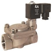
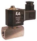
10 Name-plate 4 Name-plate In some cases the armatures/valves will be provided with a name- plate, which permitts a definite identification of the armatures/valves and shows the most important technical data to you. The name-plate should not be displaced or changed. END-Armaturen GmbH GmbH & Co. & Co. KG KG D Bad Oeynhausen +49 (0) Art.Nr.: ZA ED Serial: Serie: ARMAU Pressure range (PS): 16 bar Betriebsdruck (PS): 16 bar Pilot pressure: 6-8 bar Steuerdruck: bar G/DN: 2 Volt: Temperature range Hz: (TS): -30 C Fluidgruppe C 1 Temperatur Size (DN): (TS): C 50 / G2" Prüfdruck Testing pressure (PT): (PT): 60 bar 60 bar Herstellungsdatum: Fluidgroup: Date of manufacturing: Fig name-plate Art.No. Serial Pressure range (PS) Pilot pressure Size (DN) Testing pressure (PT) Fluidgroup Date of manufacturing article number of the valve / armature order- or production- number max. admissible working pressure of the valve / armature [bar] recommend pilot pressure for correct function of the valve / armature [bar] (only at pneumatic actuated valves / armatures) connecting size of the valve / armature testing pressure of the body of the valve / armature allowed fluidgroup of the valve / armature month and year of manufacturing of the valve / armature /2015
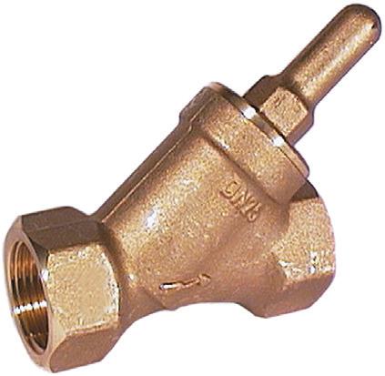
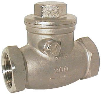
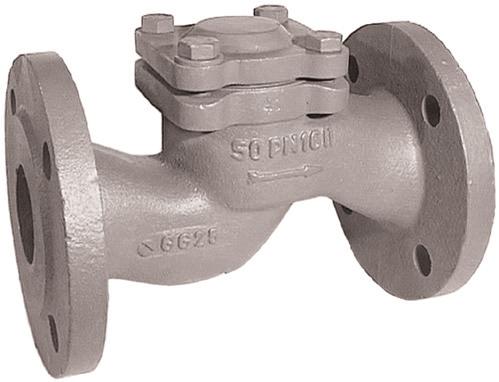
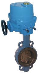
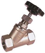
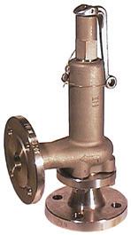
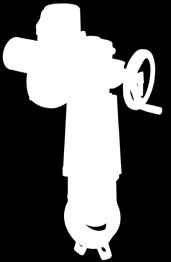
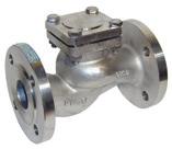
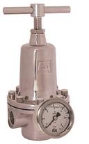
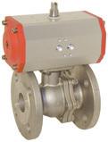
11 Non-Return valves, Swing-Check valves 5 Non-Return valves, Swing-Check valves 5.1 General Before you mount /disassemble, adjust or commission a non-return valve or a swing-check valve you must have read the Safety advice If you have not read the safety advices until now please read these important advices now and turn back to this point. 5.2 Corresponding use Non-return valves and swing-check valves are used to prevent the back-flow of media. It should only be used clean liquids and gases, on which the material of the valves and the material of the sealings will be resistant. Pollution or using outside the nominal pressure range and/or the nominal temperature range should causes damages on the valves especially on the seals. 5.3 Operation Non-return valves and swing-check vales need no special operation. 5.4 Mounting / Disassemble The mechanical mounting is identical in all variants. It differs only by the type of connection. Observe the flow direction which is specified on the valve body. The installation of a swing-check valves will have take place that the flap of the swing-check valve will close by the force of gravity automatically. Please observe that that the installation of the swing-check valve / non-return valve will have influence on the opening pressure. Remove all transport safety devices (e.g. plugs or caps). Observe that there won`t be any parts of the package or other pollution in the armature. Before mounting swing-check valve / non-return valve clean up the pipes. Pollution will reduce the safety and the duration of life of the armature. o.k. o.k. Fig non-return valve, swing-check valve, installation (Fig.: Art. TR100025). 03/
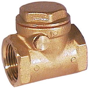
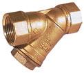
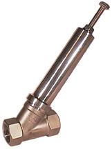
12 Non-Return valves, Swing-Check valves Avoid stress in case of non align pipes Mounting with threaded connection Before lay on sealing compounds, check the hardly screwing by the pipes into the valve body. Lay on the correct sealing compounds on the pipes end. By using PTFE-ribbon or hemp seals observe the screw direction. Don`t use sealing compounds which are not prescribed for your employment. Screw the pipes into the connection ends of the valve. Strike up the pipes with pressure after that time the manufacturer of the sealing compounds pretends to harden it. Check the tightness of all connections. sealing compound harden! o.k. flow direction Fig non-return valves, swing-check valves, mounting with threaded connection (Fig.: Art. BH120025) Mounting with welded connection Before welding the valve between the pipes you have to disassemble the bonnet of the non-return valve first, to prevent the damage of the seals /2015
13 Non-Return valves, Swing-check valve Disassemble of the bonnet and the inner parts Clamp the valve between a vice carefully. By using guard plates you can prevent the damage of the ends of the valve body. Loosen the bonnet with a fit spanner. Screw the bonnet out of the body. By doing this be very careful, because there will be a resilience on the bonnet. Take the spring and the inner part out of the bonnet and put the parts aside. resilience Fig non-return valves, swing check valve, disassembly of the bonnet and the inner parts (Fig.: Art. EB310064) Welding the body between pipes By welding the valve body with the pipes observe appropriate demands and guide lines. The safety demands be welding are depending on the place and the position of the point of weld. Welding the parts in a serviceable device/machine/plant the potential of danger is as higher as welding the parts in a welding room. If appropriate inform the shift foreman / safety engineer or the works manager and the fire brigade of your factory. By welding observe your own national guide lines about safety and the prevention of accidents. 03/
14 Non-Return valves, Swing-Check valves o.k. flow direction Fig non-return valves, swing-check valves, welding of the body (Fig.: body of Art. EB310064) Mounting of the bonnet and the inner parts Before mounting the bonnet and the inner parts let the body cool down. Insert the inner parts and the spring into the body. Take care about the correct placement of the inner parts and the spring. Screw the bonnet into the body. Check the correct position of the sealing at the bonnet and take care that there will be no pollution on the sealing or on the seat. Tighten the bonnet with a fit spanner. Check the tightness of all connections. cool down o.k. Fig non-return valve, swing-check valve, mounting of the bonnet and the inner parts (Fig.: Art. EB310064) /2015
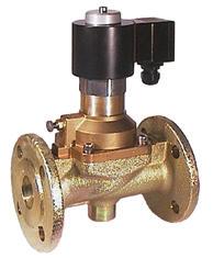
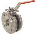
15 Non-Return valves, Swing-Check valves Mounting of the valve with flanged connection In the following description we assume that you have mounted the flanges at the end of the pipes and the valve (welded flanges) and they are cooled down.. Push the valve between the flanges by using the appropriate seals. This process must happen easily to avoid the damage of the seals. Align the borings of the flanges and put some fit screws through the holes. Screw the fit nuts onto the screws and tighten them up crosswise. Fasten all screws crosswise and check the function of the valve. Observe the maximum torque of the screws. Check the tightness of all connections. o.k. flow direction Fig non-return valves, swing-check valve, mounting with flanged connection (Fig.: Art. KU3000xx) 5.5 Maintenance Before you maintain or shut down a non-return valve / swing-check valve you have to read the Safety advice If you have not read the safety advices until now, read this important advices now and turn back to this page. Non-return valves need on maintenance In case of a defect of the valve make a contact to the supplier. The telephone number will be found on the back or these operation and installation manual. If you determinate that there is a damage to the valve switch off the device/ machine/ plant! However before doing this, it is essential to refer to the Safety advice. 03/
16 Notice /2015
17 Notice 03/
18 6 Declaration in conformity as defined by Pressure-Equipment-Directive 97/23/EC
19


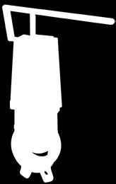
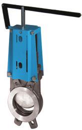


20 watergates knife-gate-valves - Stoffschieber END-Armaturen GmbH & Co. KG Oberbecksener Str.78 D Bad Oeynhausen Telefon +49 (0) 5731 / Telefax +49 (0) 5731 / Internet post@end.de Watergates GmbH & Co. KG Oberbecksener Str.70 D Bad Oeynhausen Telefon +49 (0) 5731 / Telefax +49 (0) 5731 / Internet post@watergates.de
Operation and Installation Manual Ball Valves
 Operation and Installation Manual Ball Valves END-Armaturen GmbH & Co. KG Oberbecksener Str. 78 D-32547 Bad Oeynhausen Telefon (05731) 7900-0 Telefax (05731) 7900-199 http://www.end.de Impressum by END-Armaturen
Original Operating Manual Pneumatic Actuator ED /EE
 Original Operating Manual Pneumatic Actuator ED /EE acc. to annex VI of the Directive 2006/42/EC END-Armaturen GmbH & Co. KG Oberbecksener Str. 78 D-32547 Bad Oeynhausen Telefon (05731) 7900-0 Telefax
Original Operating Manual Motor Control Valve MBA / MBK NBA / NBK EBA / EBK
 Original Operating Manual Motor Control Valve MBA / MBK NBA / NBK EBA / EBK acc. to annex VI of the Directive 2006/42/EC END-Automation GmbH & Co. KG Postfach (PLZ 32503) 100 342 Oberbecksener Str. 78
watergates knife-gate-valves - Stoffschieber
 watergates knife-gate-valves - Stoffschieber Original Operating Manual Knife-gate valves acc. to annex VI of the Directive 2006/42/EC [Contact] Watergates GmbH & Co. KG Postfach (PLZ 32503) 101 321 Oberbecksener
Original Operating Manual Pressure Actuated Valve
 Original Operating Manual Pressure Actuated Valve DG2D1 DG2D2 DG2D3, DA2D3, DL2D3, DM2D3, DG3D3, DF3D acc. to annex VI of the Directive 2006/42/EC END-Armaturen GmbH & Co. KG Postfach (PLZ 32503) 100 341
Combined operated solenoid valves.../ax..
 0032 Combined operated solenoid valves.../ax.. (version acc. to European Directive 2014/34/EU(ATEX)) Mounting and Operating Manuel for explosion proofed solenoids END-Automation GmbH & Co. KG D-32547 Bad
Servo assisted solenoid valves.../ax..
 Servo assisted solenoid valves.../ax.. (version acc. to European Directive 2014/34/EU(ATEX)) Mounting and Operating Manuel for explosion proofed solenoids END-Armaturen GmbH & Co. KG Postfach (PLZ 32503)
Operating Instructions for Magnetic Filter. Model: MFR-00
 Operating Instructions for Magnetic Filter Model: MFR-00 1. Contents 1. Contents... 2 2. Note... 3 3. Instrument Inspection... 3 4. Regulation Use... 3 5. Operating Principle... 4 6. Mechanical Connection...
Operating Instructions K Always on the safe side.
 Operating Instructions K9 4953. Always on the safe side. KaVo Dental GmbH Wangener Straße 78 D-88299 Leutkirch Tel.: 0 75 61 / 86-150 Fax: 0 75 61 / 86-265 A 1 User information...2 A 1.1 Meaning of the
Operating Instructions Garlock Butterfly Valves DN : mm / 2-24
 Operating Instructions Garlock Butterfly Valves DN : 50-600 mm / 2-24 PN : 10 / 16 Type: GAR-SEAL SAFETY-SEAL STERILE-SEAL MOBILE-SEAL Conformity declaration... 14 0 Introduction... 15 1 Proper use...
Storage, operating and maintenance instructions for AZ plug valves and Standard valves
 ARMATUREN Plug - Valves metallic with PTFE Sleeve 2-7 way Storage, operating and maintenance instructions for AZ plug valves and Standard valves Plug - Valves FEP/PFA - lined, 2-3 way Butterfly - Valves
Mounting and Operating Instructions EB 8227 EN. Pneumatic Control Valve Type 3331/BR 31a Special version Type 3331/3278. Type 3331 Butterfly Valve
 Pneumatic Control Valve Type 3331/BR 31a Special version Type 3331/3278 Type 3331 Butterfly Valve Fig. 1 Type 3331/BR 31a (below) and Type 3331/3278 (top) Mounting and Operating Instructions EB 8227 EN
Mounting and Operating Instructions EB 8222 EN. Type 3310/AT and Type 3310/3278 Pneumatic Control Valves. Type 3310 Segmented Ball Valve
 Type 3310/AT and Type 3310/3278 Pneumatic Control Valves Type 3310 Segmented Ball Valve Fig. 1 Type 3310/3278 with positioner Fig. 2 Type 3310/AT Mounting and Operating Instructions EB 8222 EN Edition
Content Copyright...1 Disclaimer...2 General advice...3 Safety Instructions...4 References Of Legal Regulations For Operation...4 Hints...5 Scope Of D
 Version 1.01 (10.10.2013) Installation Instructions DAB / DAB+ Antenna module Articlenr. 39336 VW Sharan 7N www.kufatec.de Kufatec GmbH & Co. KG Dahlienstr. 15 23795 Bad Segeberg e-mail: info@kufatec.de
Type Operating Instructions. Bedienungsanleitung Manuel d utilisation. 2/2-way solenoid valve 2/2-Wege-Magnetventil Électrovanne 2/2 voies
 Type 5404 2/2-way solenoid valve 2/2-Wege-Magnetventil Électrovanne 2/2 voies Operating Instructions Bedienungsanleitung Manuel d utilisation Contents 1 Operating instructions...2 2 Intended use...3 3
Pressure relief valve
 Pressure relief valve Operating manual Series DHV 712 Version BA-2015.10.20 EN Print-No. 300 510 TR MA DE Rev001 ASV Stübbe GmbH & Co. KG Hollwieser Straße 5 32602 Vlotho Germany Phone: +49 (0) 5733-799-0
Declaration of Conformity as per Directive 97/23/EC
 Declaration of Conformity as per Directive 97/23/EC The manufacturer declares that:, 47906 Kempen, Germany PTFE-lined Rotary plug valves Series 23e, with packing with lever for 90 operation with worm gear
Content Copyright...1 Disclaimer...2 General Advice...3 Safety Instructions...4 Reference Of Legal Regulations For Operation...4 Hints...5 Scope Of De
 Version 1.01 (11.10.2013) Installation Instructions DAB / DAB+ Antenna module Articlenr. 39338 VW Golf 6 www.kufatec.de Kufatec GmbH & Co. KG Dahlienstr. 15 23795 Bad Segeberg e-mail: info@kufatec.de Content
Operating and installation instructions
 Strainer PN6-160 1.0 General information on operating instructions...2-2 2.0 Notes on possible dangers...2-2 2.1 Significance of symbols... 2-2 2.2 Explanatory notes on safety information... 2-2 3.0 Storage
Operating Instructions
 Armaturen GmbH Armaturen, Rohre, Sonderteile aus Edelstahl fittings, pipes, special parts of stainless steel Operating Instructions BaseCom butterfly valve Rev.0 / 12.12.2009 Page 1 of 8 BA52290GB.doc
Mounting and Operating Instructions EB 8111/8112 EN. Valve Series V2001 Globe Valve Type 3321
 Valve Series V2001 Globe Valve Type 3321 Fig. 1 Type 3321 Valve with mounted rod-type yoke for pneumatic or electric actuators (partial view) Mounting and Operating Instructions EB 8111/8112 EN Edition
Operating and Maintenance Manual. for. HADEF overhead crane. as jointed crane TA
 5.52.714.00.1.0 Edition 03.2004 GB Operating and Maintenance Manual for HADEF overhead crane as jointed crane TA Subject to changes. 1 HADEF Table of Contents 1 General Page 3 2 Product description Page
MANUAL. Single charger
 MANUAL Single charger HST-PR-2830 & HST-PR-2830USA for HS-Technik batteries HST-PR-18xx HST-PR-14xx issue date: November 2016 Table of contents Page 1. Basic information...3 1.1. Purpose of this document...3
Mounting and Operating Instructions EB 8097 EN. Pneumatic Control Valves Type and Type
 Pneumatic Control Valves Type 3347-1 and Type 3347-7 Hollow-mold cast body with welding ends Full-mold cast body with threaded connections Fig. 1 Type 3347-7 Control Valve with Type 3277 Actuator and integral
Installation Instructions RFK VW Amarok
 Version 1.04 (09.06.2015) Installation Instructions RFK VW Amarok Articlenr. 38352 VW Amarok www.kufatec.de Kufatec GmbH & Co. KG Dahlienstr. 15 23795 Bad Segeberg e-mail: info@kufatec.de Content Copyright...
T R A N S L A T I O N Declaration of Conformity as per Directive 2014/68/EU
 T R A N S L A T I O N Declaration of Conformity as per Directive 2014/68/EU The manufacturer declares that: Pfeiffer Chemie-Armaturenbau GmbH, 47906 Kempen, Germany Butterfly valves BR14a, BR14b, BR14b-Type
Type 5411, Operating Instructions. Bedienungsanleitung Manuel d utilisation
 Type 5411, 5413 3/2 or 4/2 way solenoid valve 3/2 oder 4/2-Wege-Magnetventil Électrovanne 3/2 ou 4/2 voies Operating Instructions Bedienungsanleitung Manuel d utilisation 1 THE OPERATING INSTRUCTIONS The
Safety. Operating instructions Solenoid valve VGP DANGER. Contents WARNING CAUTION. Changes to edition Elster GmbH Edition 10.
 27 Elster GmbH Edition.7 Translation from the German 344297 D F NL I E DK S N P GR TR CZ PL RUS H www.docuthek.com Operating instructions Solenoid valve Contents Solenoid valve... Contents... Safety....
Mounting and Operating Instructions EB 8039 EN. Type 3351 Pneumatic On/off Valve. Type 3351 Pneumatic On/off Valve. Type 3351 Pneumatic On/off Valve
 Type 3351 Pneumatic On/off Valve Type 3351 Pneumatic On/off Valve Type 3351 Pneumatic On/off Valve Version with handwheel Mounting and Operating Instructions EB 8039 EN Edition May 2016 Definition of signal
Installation instruction Sound Booster Pro Active Sound
 Version 1.03 (20.04.2016) Installation instruction Sound Booster Pro Active Sound Article no. 40180 Audi A6 4G Audi A7 4G Audi Q5 8R www.kufatec.de Kufatec GmbH & Co. KG Dahlienstr. 15 23795 Bad Segeberg
Mounting and Operating Instructions EB 8097 EN. Type and Type Pneumatic Control Valves
 Type 3347-1 and Type 3347-7 Pneumatic Control Valves Type 3347-7, cast body with welding ends Type 3347-7, bar stock body with threaded connections Mounting and Operating Instructions EB 8097 EN Edition
Pneumatic Control Valve Assembly Type 3331/3278
 Pneumatic Control Valve Assembly Type 3331/3278 Fig. 1 Type 3331/3278 Pneumatic Control Valve Assembly 1. Design and principle of operation The pneumatic control valve assembly consists of a Type 3331
Mounting and operating instructions EB 8093 EN. Series 240 Pneumatic Control Valve for Cryogenic Temperatures. Type and
 Series 240 Pneumatic Control Valve for Cryogenic Temperatures Type 3248-1 and 3248-7 Fig. 1 Type 3248 Cryogenic Valve with Type 3277 Pneumatic Actuator as globe and angle valve Mounting and operating instructions
Mounting and operating instructions EB 8220 EN. Pneumatic Butterfly Valve Type 3335/AT and Type 3335/3278. Fig. 2 Type 3335/AT
 Pneumatic Butterfly Valve Type 3335/AT and Type 3335/3278 Fig. 2 Type 3335/AT Fig. 1 Type 3335/3278 with attached positioner Mounting and operating instructions EB 8220 EN Edition November 2000 Contents
Mounting and Operating Instructions EB 8091 EN. Pneumatic Control Valve Type and Type Type with 120 cm 2 actuator
 Pneumatic Control Valve Type 3510-1 and Type 3510-7 Type 3510-1 with 120 cm 2 actuator Type 3510-7 with 120 cm 2 actuator and integrated positioner Type 3510-1 with 60 cm 2 actuator Fig. 1 Pneumatic control
Type Operating Instructions. Bedienungsanleitung Manuel d utilisation. 2/2-Way Solenoid Valve 2/2-Wege-Magnetventil Électrovanne à 2/2 voies
 Type 5282 2/2-Way Solenoid Valve 2/2-Wege-Magnetventil Électrovanne à 2/2 voies Operating Instructions Bedienungsanleitung Manuel d utilisation 1 OPERATING INSTRUCTIONS The operating instructions contain
Series 250 Pneumatic Control Valves Type and
 Series 250 Pneumatic Control Valves Type 3252-1 and 3252-7 Fig. 1 Type 3252 High-pressure Valve with Type 3277 Pneumatic Actuator and Type 3767 i/p Positioner Edition November 1998 Mounting and operating
Mounting and Operating Instructions EB 8048 EN. Type and Type Pneumatic Control Valves Type 3249 Aseptic Angle Valve
 Type 3249-1 and Type 3249-7 Pneumatic Control Valves Type 3249 Aseptic Angle Valve Ball body version Special version with packing Type 3249-7 Control Valve with Type 3277 Actuator and integrated positioner
Operating and Installation Instructions Pulsation Damper P Series for Pumps of the BIOCOR Series
 Operating and Installation Instructions Pulsation Damper P Series for Pumps of the BIOCOR Series ought to be studied before installing the pulsation damper Original Instruction Introduction ALMATEC pulsation
Mini UHV gate valve with manual actuator with pneumatic actuator
 Mini UHV gate valve with manual actuator with pneumatic actuator This manual is valid for the valve ordering numbers: 004/8/3/34-. E0/08 004/8/3/34-. E//3/4 004/8/3/34-. E//3/4 004/8/3/34-. E4/4/34/44
Type 6213 EV, 6281 EV
 Type 6213 EV, 6281 EV 2/2-way solenoid valve 2/2-Wege-Magnetventil Électrovanne 2/2 voies Operating Instructions Bedienungsanleitung Manuel d utilisation 1 OPERATING INSTRUCTIONS The operating instructions
EN Operating manual. Motorised zone valve. Three-way, 22 mm & 28 mm 3PV2, 3PV8 & VRMH3
 EN Operating manual Motorised zone valve Three-way, 22 mm & 28 mm 3PV2, 3PV8 & VRMH3 This manual ensures safe and efficient use of the 3PV2 or 3PV8 force-actuated three-way valve with spring-loaded return
AC 100. Operating instructions Pneumatic Crimper AC 100. Date of issue: 05/2010. Keep for future use!
 Operating instructions Pneumatic Crimper AC 100 Date of issue: 05/2010 Keep for future use! SAFETY SAFETY Basic information The basic prerequisite for ensuring safe use and continuous operation of the
Turbocharger / A100-L Original assembly instructions English
 Assembly Instructions Turbocharger / A100-L Original assembly instructions English This document is valid for the A100-L series: A165-L, A170-L, A175-L, A180-L, A185-L, A190-L Purpose The assembly instructions
back to main page Type: Butterfly valves Instructions and Operation Manual Warning! Warning! Danger for life! 1. Intended use Danger for life!
 Instructions and operation manual for butterfly valves This manual is intended to support the users of Herberholz butterfly valves type HRD/HRA, RD/RA, LDKE/LDKF for installation, operation and maintenance
HST-BL-2830MS & HST-BL-2830MS-USA
 HST-BL-2830MS & HST-BL-2830MS-USA Release date: 02/2017 High - System - Technik Im Martelacker 12 D-79588 Efringen-Kirchen Phone 0 76 28-91 11-0 Fax 0 76 28-91 11-90 E-Mail: info@hs-technik.com Web: www.hs-technik.com
Installation manual Complete set active Sound incl. Soundbooster Skoda Octavia 5E
 Version 1.04 (01.06.2017) Installation manual Complete set active Sound incl. Soundbooster Skoda Octavia 5E Articel no. 40590 www.kufatec.de Kufatec GmbH & Co. KG Dahlienstr. 15 23795 Bad Segeberg e-mail:
Type Operating Instructions. Bedienungsanleitung Manuel d utilisation. 2/2-way solenoid valve 2/2-Wege-Magnetventil Électrovanne 2/2 voies
 Type 6027 2/2-way solenoid valve 2/2-Wege-Magnetventil Électrovanne 2/2 voies Operating Instructions Bedienungsanleitung Manuel d utilisation 1 OPERATING INSTRUCTIONS The operating instructions contain
Mounting and Operating Instructions EB 8111/8112 EN. Series V2001 Valves Type 3321 Globe Valve
 Series V2001 Valves Type 3321 Globe Valve Type 3321 Globe Valve with rod-type yoke and Type 3372 Electropneumatic Actuator (350 cm²) Mounting and Operating Instructions EB 8111/8112 EN Edition June 2013
These installation and maintenance instructions must be read in full and completely understood before the installation!
 These installation and maintenance instructions must be read in full and completely understood before the installation! 1. General information on the installation and maintenance instructions These instructions
Manufacturer s Declaration as per EU-Directives Page 1 of 2
 The manufacturer Manufacturer s Declaration as per EU-Directives Page 1 of 2 BRAY Armaturen & Antriebe Europa, D47807 Krefeld for Butterfly valves all Series 2[.].& Series 3[.] : Series 20/21 (2 body-halves
original operating manual Operating manual Translation of the Item-No.: ,
 Translation of the original operating manual Operating manual Item-No.: 015 431 551, 015 431 581 Important! Copyright The operating manual is always to be read before commissioning the equipment. No warranty
Installation and Operating Instructions
 Original Installation and Operating Instructions Hawle E2 Valve with Flange Outlet, System 2000 or PE Spigot Ends Table of Contents A) General...... 2 A1 Symbols..... 2 A2 Intended use... 2 A3 Labeling...
Pressure Reducing Valve Type 2114/2415
 Pressure Reducing Valve Type 2114/2415 Fig. 1 Type 2114/2415 1. Design and principle of operation The Type 2114/2415 Pressure Reducing Valve consists of the Type 2114 Valve and the Type 2415 Actuator.
KeContact P20. User manual
 KeContact P20 User manual Comments to this manual In this manual you will find warnings against possible dangerous situations. The used symbols apply to the following meanings:!! WARNING! Indicates a potentially
Installation, Operating & Maintenance Instructions. HV gate valve with pneumatic actuator. Series 110 DN mm (I. D.
 Installation, Operating & Maintenance Instructions HV gate valve with pneumatic actuator Series 110 DN 250 320 mm (I. D. 10" 12") This manual is valid for the following product ordering numbers: 11048-.
Installation, Operating & Maintenance Instructions. UHV gate valve with pneumatic actuator. Series 108 DN mm (I. D. 2½ 8 )
") Installation, Operating & Maintenance Instructions UHV gate valve with pneumatic actuator Series 108 DN 63 200 mm (I. D. 2½ 8 ) This manual is valid for the following product ordering numbers: 108.. -.
Installation, Operating & Maintenance Instructions UHV gate valve with pneumatic actuator Series 108 DN 63 200 mm (I. D. 2½ 8 ) This manual is valid for the following product ordering numbers: 108.. -.
Operating Instructions: Hand-operated, PTFE-lined butterfly valves, Series 22/23
 0 Introduction These instructions are intended to assist users of BRAY PTFE-lined butterfly valves, Series 22/23 in fitting, operating and servicing valves. Risks may arise and the manufacturer's warranty
Mounting and Operating Instructions EB 8135/8136 EN. Series V2001 Valves Type 3535 Three-way Valve for Heat Transfer Oil
 Series V2001 Valves Type 3535 Three-way Valve for Heat Transfer Oil Type 3535 Three-way Valve with bellows seal and rod-type yoke (partial view) Mounting and Operating Instructions EB 8135/8136 EN Edition
Type Operating Instructions. Bedienungsanleitung Manuel d utilisation. 2/2-Way Solenoid Valve 2/2-Wege-Magnetventil Électrovanne à 2/2 voies
 Type 5282 2/2-Way Solenoid Valve 2/2-Wege-Magnetventil Électrovanne à 2/2 voies Operating Instructions Bedienungsanleitung Manuel d utilisation Contents 1 Operating Instructions... 2 2 Authorized use...
User Guide. Lubricus Lubrication System LUB-D1/LUB-D2/LUB-D3/LUB-D4 (24 VDC)
") User Guide Lubricus Lubrication System LUB-D1/LUB-D2/LUB-D3/LUB-D4 (24 VDC) version 04/2013 Content General Information 3 Warning 3 Scope of Supply 3 Overview 3 General safety details 4 Intended use 4
User Guide Lubricus Lubrication System LUB-D1/LUB-D2/LUB-D3/LUB-D4 (24 VDC) version 04/2013 Content General Information 3 Warning 3 Scope of Supply 3 Overview 3 General safety details 4 Intended use 4
NEOTECHA NTB-NTC BALL VALVES INSTALLATION AND MAINTENANCE INSTRUCTIONS
 Before installation these instructions must be fully read and understood 2 SAFETY Please also read through these notes carefully. 2.1 General potential danger due to: a. Failure to observe the instructions
Globe Valve Type Fig. 1 Type 3241 Globe Valve. Mounting and Operating Instructions EB EN
 Globe Valve Type 3241 Fig. 1 Type 3241 Globe Valve Mounting and Operating Instructions EB 8015-1 EN Edition July 2012 Contents Contents Page 1 Design and principle of operation.................... 4 2
OPERATING INSTRUCTIONS
 Conveyor Belt Misalignment Switch Type MRS 001 Device Identification No.: 91.055 301.001 OPERATING INSTRUCTIONS 2 CE-Sign and Conformity The device meets the requirements of the valid European and national
Compact System NRGS 11-2 NRGS Original Installation Instructions English
 Compact System NRGS 11-2 NRGS 16-2 EN English Original Installation Instructions 810366-05 1 Contents Important Notes Page Usage for the intended purpose...4 Safety note...4 LV (Low Voltage) Directive
Rotary feed-through DDF-S/-KS
 Translation of the Original Operating Manual Rotary feed-through DDF-S/-KS Assembly and Operating Manual Superior Clamping and Gripping Imprint Imprint Copyright: This manual remains the copyrighted property
Operating and installation instructions
 Check valves Contents 1.0 General information on operating instructions...2-2 2.0 Notes on possible dangers...2-2 2.1 Significance of symbols... 2-2 2.2 Explanatory notes on safety information... 2-2 3.0
INSTRUCTION MANUAL. I/P Converter DSG BXXY3Z DSG BXXY4Z
 INSTRUCTION MANUAL I/P Converter DSG BXXY3Z DSG BXXY4Z Revision 2.0 3.626 016136 en Page 1/15 Should you have any questions concerning the I/P converter, please contact the Service Department of the Product
Drive Unit e-drive1. Installation instructions 04/2014. English translation of the original German installation instructions
 Drive Unit e-drive1 Installation instructions 04/2014 English translation of the original German installation instructions Contents Foreword... 3 Availability... 3 Structural features in the text... 3
Contents Copyright...2 General advice...2 Safety instructions...3 References of legal regulations for operation...3 Space of delivery for 37998, 37998
 Version 1.05 (22.02.2013) Installation instruction Parking assist Front + Rear Article no.37998, 37998-1, 37998-2 39745 VW Touareg 7P www.kufatec.de Kufatec GmbH & Co. KG Dahlienstr. 15 23795 Bad Segeberg
Printed: Doc-Nr: PUB / / 000 / 00
 ORIGINAL OPERATING INSTRUCTIONS Hilti HTE-P 33 dispenser It is essential that the operating instructions are read before the tool is operated for the first time. Always keep these operating instructions
Type Operating Instructions. Bedienungsanleitung Manuel d utilisation
 Globe control valve, pneumatically operated Actuator sizes 40 mm - 125 mm, Nominal diameter DN10-65 Kolbengesteuertes Geradsitzventil Antriebsgrößen 40 mm - 125 mm, Nennweiten DN10-65 Vanne à siège droit
Installation, Operation, and Maintenance Manual
 Industrial Process Installation, Operation, and Maintenance Manual Series PBV Plastic Lined Ball Valve Table of Contents Table of Contents Introduction and Safety...2 Safety message levels...2 User health
Installation manual portable distributors
 EN Installation manual portable distributors EN 60003206 Issue 11.2016 15/11/2016 Table of contents 1 About this manual 3 1.1 Structure of the warnings 3 1.2 Symbols used 4 1.3 Signal words used 4 2 Intended
Operating and installation instructions
 Pneumatic actuators DP34 Tandem / DP34 Tridem DP34T Contents DP34Tri 1.0 General information on operating instructions...2-2 2.0 Notes on possible dangers...2-2 2.1 Significance of symbols...2-2 2.2 Explanatory
Installation and Operational Instructions for ROBATIC -clutch Types _.0 and _.0 Sizes 3 7
 Please read these Installation and Operational Instructions carefully and follow them accordingly! Ignoring these Instructions may lead to malfunction or to clutch failure, resulting in damage to other
Swing Piston Compressors and Vacuum Pumps
 Swing Piston Compressors and Vacuum Pumps NPK 018 AC Pressure NPK 018 DC Pressure NPK 018 AC Vacuum NPK 018 DC Vacuum Operating and Installation Instructions Read and observe these Operating and Installation
Installation, Operating & Maintenance Instructions. HV angle valve with pneumatic actuator single acting with closing spring (NC)
") Installation, Operating & Maintenance Instructions HV angle valve with pneumatic actuator single acting with closing spring (NC) Series 264 DN 10 50 mm (I. D. ⅜" 2") HV inline valve with pneumatic actuator
Installation, Operating & Maintenance Instructions HV angle valve with pneumatic actuator single acting with closing spring (NC) Series 264 DN 10 50 mm (I. D. ⅜" 2") HV inline valve with pneumatic actuator
DC Master 24/ A
 USERS MANUAL DC Master 24/12 50-60A DC-DC converter MASTERVOLT Snijdersbergweg 93, 1105 AN Amsterdam The Netherlands Tel.: +31-20-3422100 Fax.: +31-20-6971006 www.mastervolt.com ENGLISH Copyright 2015
Exchange of rollers from the XTS-Mover
 Service documentation for AT901-0050-0550 and AT9011-00x0-0550 Version: Date: 1.0 0.10.017 Table of contents Table of contents 1 Foreword... 5 1.1 Notes on the documentation... 5 1. Documentation issue
Safety. Operating instructions Solenoid valve for gas VG 6 VG 15/10 DANGER. Contents WARNING CAUTION. Changes to edition 07.15
 17 Elster GmbH Edition 1.17 Translation from the German 519 D F NL I E DK S N P GR TR CZ PL RUS H www.docuthek.com Operating instructions Solenoid valve for gas VG VG 15/1 Contents Solenoid valve for gas
Service - Safety Manual
 Service - Safety Manual Mounting and maintenance instructions Linear Units LT50 series Code Unit Serial number Date by Linear Units LT50 series Table of contents 1 Safety 3 1.1 Significance of the manual
HV angle valve with single acting pneumatic actuator and closing spring (NC)
") Installation, Operating & Maintenance Instructions HV angle valve with single acting pneumatic actuator and closing spring (NC) Series 264 DN 100 160 mm (I. D. 4 6 ) This manual is valid for the following
Installation, Operating & Maintenance Instructions HV angle valve with single acting pneumatic actuator and closing spring (NC) Series 264 DN 100 160 mm (I. D. 4 6 ) This manual is valid for the following
VAG CEREX M300 Butterfly Valve
 Operation and Maintenance Instructions VAG CEREX M300 Butterfly Valve KAT 1310-B Edition4 12-17 Table of Contents 1 General 3 1.1 Safety 3 1.2 Proper use 3 1.3 Identification 3 VAG reserves the right to
CETOP POSITION PAPER PP 07
 CETOP POSITION PAPER PP 07 MACHINERY DIRECTIVE 2006/42/EC Valid since 26 th May 2010 CETOP General Secretariat Lyoner Straße 18 D-60528 Frankfurt am Main Phone: +49 69 6603 1201 Fax: +49 69 6603 2201 E-mail:
Operating & Maintenance Manual For Steam Conditioning Valve
 For Steam Conditioning Valve 1 Table of Contents 1.0 Introduction 3 2.0 Product description 3 3.0 Safety Instruction 4 4.0 Installation and Commissioning 5 5.0 Valve Disassembly 6 6.0 Maintenance 6 7.0
HST -LS Interlocking device (Translation of Original Manual)
") Installation and Operating Manual for Components HST -LS Interlocking device (Translation of Original Manual) HST-LS Ident.-No.: 10268 HST-LS Ident.-No.: 10269 HST-LS, pictured Ident-Nr. 10269 The image
Installation and Operating Manual for Components HST -LS Interlocking device (Translation of Original Manual) HST-LS Ident.-No.: 10268 HST-LS Ident.-No.: 10269 HST-LS, pictured Ident-Nr. 10269 The image
Turbocharger / VTR..0, VTR..1 Original assembly instructions English
 Assembly Instructions Turbocharger / VTR..0, VTR..1 Original assembly instructions English This document is valid for the VTR..0/..1 series: VTR160, VTR200, VTR250, VTR320, VTR400 VTR161, VTR201, VTR251,
Keystone Butterfly valves ParaSeal Installation and maintenance instructions
 Before installation these instructions must be fully read and understood Please read these instructions carefully Hazard potentials: disregarding of instructions improper use of product insufficiently
EPS 16 ATEX 1121 X, IECEx EPS X Solenoid coil Type 06xx Magnetspule Typ 06xx Bobine magnétique Type 06xx. Operating Instructions
 , IECEx EPS 16.0053X Solenoid coil Type 06xx Magnetspule Typ 06xx Bobine magnétique Type 06xx Device with II 2G/D Ex approval Geräte mit II 2G/D Ex Zulassung Appareils avec mode de protection II 2G/D Ex
Mounting and Operating Instructions EB 5894 EN. Electric control valves with jet pump. Flanged version of valve with jet pump
 Electric control valves with jet pump Type 3267/5824, Type 3267/5825, Type 3267/3374, Type 3267/3274 Pneumatic control valves with jet pump Type 3267-1, Type 3267-7 Flanged version of valve with jet pump
Hook-in coupling n.b EH EH Operating Instruction English
 Revision A Datum 10.05.2013 Ersteller NH This operating instruction is not subject to the updating Hook-in coupling n.b. 25 1-EH-025-1-..-..-. 1-EH-025-4-..-.. 1 This coupling is a quality product, in
Angle seat valve with diaphragm actuator VZXA-...-M
 Angle seat valve with diaphragm actuator VZXA-...-M Instructions Operating (Translation of the original instructions) Festo AG & Co. KG Ruiter Straße 82 73734 Esslingen Germany +49 711 347-0 www.festo.com
Installation manual Complete set active Sound incl. Soundbooster Audi A4 8E
 Version 1.01 (18.02.2015) Installation manual Complete set active Sound incl. Soundbooster Audi A4 8E Article no. 40566 www.kufatec.de Kufatec GmbH & Co. KG Dahlienstr. 15 23795 Bad Segeberg e-mail: info@kufatec.de
VARICOOL - V901. Injection Nozzle Valve Fig. 1
 VARICOOL - V901 Injection Nozzle Valve Fig. 1-1 - List of contents 1 1.1 1.2 1.3 1.4 1.5 1.6 1.7 2 3 4 5 6 6.1 6.2 6.3 6.4 6.5 6.6 6.7 7 Operating instructions Installation Delivery status Installation
Installation and Operational Instructions for ROBATIC -clutch Type and Type Sizes 3 9
 Please read the Operational Instructions carefully and follow them accordingly! Ignoring these Instructions may lead to malfunctions or to clutch failure, resulting in damage to other parts. Contents:
F-4600 INLINE ULTRASONIC FLOW METER Installation and Operation Guide
 F-4600 INLINE ULTRASONIC FLOW METER Installation and Operation Guide 11451 Belcher Road South, Largo, FL 33773 USA Tel +1 (727) 447-6140 Fax +1 (727) 442-5699 1054-7 / 34405 www.onicon.com sales@onicon.com
USERS MA UAL Bellow sealed valve Fig.229, 230, 234, 235 Edition: 1/2008
 诲眾 ᓠ 睂睄 睄 ɞ 1/7 ZETKAMA Spółka Akcyjna ul. 3 Maja 12 PL 57-410 Ścinawka Średnia USERS MA UAL Bellow sealed valve Fig.229, 230, 234, 235 Edition: 1/2008 Date: 01.01.2008 CONTENTS 1. Product description
Control Gate Valve with stepper motor actuator
 Control Gate Valve with stepper motor actuator This manual is valid for the valve ordering numbers: 64036-.E52 and 64040-.E52 The respective product identification is given on each valve in the following
Controlflex Installation and operating manual
 SCHMIDT-KUPPLUNG GmbH Controlflex Installation and operating manual Controlflex Controlflex, the electrically insulated encoder coupling: the exclusive central element provides precise transmission of