ISO Interface Solenoid Valve/SIZEq Metal Seal. Standard Specifications. Fluid Operating pressure. Ambient and fluid temperature
|
|
|
- Maximilian Bruce
- 6 years ago
- Views:
Transcription

 Double solenoid (FG-D) Reverse pressure (YZ-S) Reverse pressure (YZ-D) Closed centre (FHG-D) xhaust centre (FJG-D) Double pilot check (FPG-D) Pressure centre (FLG-D) Standard Specifications")
 AXT511 B- (V) AXT511 B-3 (V) AXT511 B-4 (V) Rated voltage (V) 0V AC 50/60 Hz 00V AC 50/60 Hz 4V DC 1V DC Inrush current (A) 0.049/0.043 0.04/0.01 Holding current (A) 0.031/0.")
 85 to 1% of rated voltage Insulation Class B (130 o C) or equivalent A: With -M4 X 46 bolts for position valve, B: With -M4 X 54 bolts for 3 position valve Note) Based on JIS")
 Air supply side eff. area S (P=0.7MPa, P1=0.5MPa) () (mm ) Air exhaust side eff. area S (P=0.5MPa) () No.")
 (mm ) (Nl/min) 7 (147.5) 7 (147.5) 5.5 (1374.) 7 (1374.) 0 (79.65) (1) Min. operating frequency is based on JIS B8375. (Once every 30 days) () Based on JIS B8375-1975 (At 0.")
 150/50 m/s Shock resistance (Vibration resistance) (1) Applicable sub-plate VS7-1 (ISO")

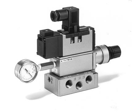
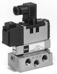
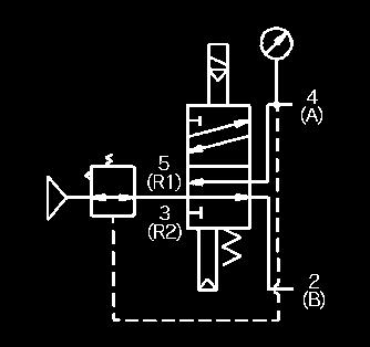
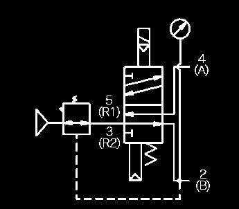
1 ISO Interface Solenoid Valve/SIZq Metal Seal SeriesVS7-6 VS7-6-FPG-D VS7-6-FG-D Accessories Mounting bolt (with washer) Packing Indicator Iight Optional Specifications VS7-6-FG-S Note: Please note that single subplates and manifolds have changed colour from platinium silver to white as standard. Valves will remain platinium silver. TA-B-5 X 35 AXT (Option) VS7-6-FHG-D Surge voltage Available suppressor Reverse R1/R port: Pressure in pressure R1=P1 pressure R=P pressure, P1=P < position 3 position Option Single solenoid (FG-S) Double solenoid (FG-D) Reverse pressure (YZ-S) Reverse pressure (YZ-D) Closed centre (FHG-D) xhaust centre (FJG-D) Double pilot check (FPG-D) Pressure centre (FLG-D) Standard Specifications Fluid Operating pressure Ambient and fluid temperature Manual override lectrical entry Lubrication Part No. A A A A AXT511 B-1 (V) AXT511 B- (V) AXT511 B-3 (V) AXT511 B-4 (V) Rated voltage (V) 0V AC 50/60 Hz 00V AC 50/60 Hz 4V DC 1V DC Inrush current (A) 0.049/ /0.01 Holding current (A) 0.031/ / Allowable voltage (V) 85 to 1% of rated voltage Insulation Class B (130 o C) or equivalent A: With -M4 X 46 bolts for position valve, B: With -M4 X 54 bolts for 3 position valve Note) Based on JIS C4003. (V): Pilot XH individual style. Interface regulator model (1) Applicable solenoid valve Regulation port Proof pressure Max. operating pressure Set pressure range Ambient and fluid temperature Pressure gauge port size Weight (kg) Air supply side eff. area S (P=0.7MPa, P1=0.5MPa) () (mm ) Air exhaust side eff. area S (P=0.5MPa) () No. of positions (Single) (Double) 3 (Closed centre) 3 (xhaust centre) 3 (Pilot check) Model VS7-6-FG-S- -Q VS7-6-FG-D- -Q VS7-6-FHG-D- -Q VS7-6-FJG-D- -Q VS7-6-FPG-D- -Q ffective area (With 1 4 sub-plate) (mm ) (Nl/min) 7 (147.5) 7 (147.5) 5.5 (1374.) 7 (1374.) 0 (79.65) (1) Min. operating frequency is based on JIS B8375. (Once every 30 days) () Based on JIS B (At 0.5MPa) Air/lnert gas 0.1 to 1.0MPa 5 to 60 o C Non-locking style, Locking style DIN connector Non-lube If provided, use turbine oil (ISO, VG3) 150/50 m/s Shock resistance (Vibration resistance) (1) Applicable sub-plate VS7-1 (ISO size q) Option Note) Shock resistance: No malfunction resulted from the impact test using a drop impact tester. The test was performed on the axis and right angle directions of the main valve and armature, for both energized and de-energized states. (Value in the initial stage.) Vibration resistance: No malfunction occurred in a one-sweep test between 8.3 and 000 Hz. Test was performed at both energized and de-energized states to the axis and right angle directions of the main valve and armature. (Value in the initial stage.) Pilot Valve/Spacifications Option/Interface regulator Model P/A P/B A/A B/B ARB50 VS7-6 A B P 1.5MPa 1.0MPa 0.1 to 0.83 Mpa 5 to 60 o C Max. operating rate (1) (cycle/sec.) mm 18 mm Note 1) Use "ABR" for pressure centre style and reverse pressure style. Note ) Synthesized effective area with position single style solenoid valve Response time () (sec) 0.05 or less or less or less or less 0.05 or less Weight (3) (kg) (3) Weight without sub-plate (Sub-plate: 0.37kg) (4) (1) and () are the rates in the condition of controlled clean air

 VS7-6-FHG-D- R 3 position double pilot check valve achieves a reduction in air leakage as a result of main valve construction which features")
2 VS7-6 Double Pilot Check Spacer/Series FPG Cylinder mid-stroke, long term retention possible. The use of the double pilot check spacer equipped with a built-in double check valve enables the cylinder to stop and remain at mid-stroke for long periods regardless of air leakage between the spool and sleeve. 3 Position Double Pilot Check Valve (Wedge packing style) VS7-6-FHG-D- R 3 position double pilot check valve achieves a reduction in air leakage as a result of main valve construction which features co-axial wedge packing (Max. leakage: cm 3 /min (ANR)). Double Pilot Check Spacer Specifications Double pilot check spacer model Applicable solenoid valve/air operated valve Leakage (cm 3 /min (ANR)) With one side solenoid energized. (With one side pilot air pressured) Both sides solenoids de-energized. (With both sides pilots not air pressured) Check Valve/Operation Pressure Characteristics The check valve will operate correctly providing that cylinder side pressure is not in excess of two times the supply pressure. P P B A VV71-FPG Series VS7-6/VSA7-6 R1 R R1 R R1 R Cylinder Speed/Stop Position Range 0 Caution Verify that there is no leakage from the pipes between valve and cylinder, and from fittings. Check for leaks by using neutral detergent solution before use. Also check the cylinder packing and the piston packing. If there is leakage, cylinder may not stop at the mid-stroke position, and could move immediately after the valve is de-energized. Be aware that if the exhaust side is restricted excessively, the intermediate stopping accuracy will decrease and will lead to improper intermediate stops. Cylinder Operation Chart Cylinder ø st ø st Supply Load factor pressure Load ø50 ø80 0.MPa 5kg 51% 8%
3 VS7-6 How to Order VS7 6 FG S 1 Q Symbol Number of solenoid Rated voltage Option Port size of sub-plate Connector S Single None Without sub-plate Connector FJG D Double N Indicator light A0 Side piping W/o connector FG YZ FHG Option Ordering source area code Code areas Japan, Asia - Australia urope N North America FPG FIG Order Made Precautions 9 0V AC 00V AC 4V DC 1V DC Others (50V or less) Contact SMC for other voltages (9) Protective class class I (Mark: ) M Direct manual override A03 Side piping 3 8 Indicator light with surge Z voltage suppressor B0 Bottom piping 1 4 Wedge packing style with MR direct manual override B03 Bottom piping 3 8 R Wedge packing style R port: 3 8 V Individual pilot XH If specifying more than one symbol, indicate them in the alphabetical order. Note: Manifold exploded view see page for details. Thread Rc (PT) F G (PF) N NPT T NPTF Be sure to read before handling. Refer to p.0-33 to 0-36 for Safety Instructions and common precautions. Caution DIN Connector (Wiring) Power Source and Wiring qmake sure all contacts are secure. wvoltage should be held within the allowable voltage range. Specifications Interface regulator model Applicable solenoid valve Regulation port Max. operating pressure Setting pressure range Ambient and fluid temperature Pressure gauge port size Weight (kg) Air supply side eff area (mm ) S (P=0.7MPa, P1=0.5MPa) Air exhaust side eff area S (P=0.5MPa) How to calculate flow rate Refer to p.0-36 for flow rate calculations. Interface Regulator Specifications P P A B A B A B ARB50 VS7-6 A B P 1.0MPa (1) 0.1 to 0.83MPa (1) 5 to 60 o C (3) mm 18 mm Note 1) Maximum operating pressure of solenoid valve is 0.9 MPa. Note ) Be sure to set pressure within setting pressure range of the solenoid valve. Note 3) Solenoid valve: Max. 50 o C Note 4) Synthesized effective area with position single style solenoid valve. Note 5) Supply pressure to interface regulator only from P port except when it is used with reverse pressure style valve. Use the ARB or ARB3 model to combine a pressure centre valve and the A and B port pressure reduction of a spacer style regulator. Use the ARB or ARB3 model to combine a reverse pressure valve and a spacer style regulator. The P port pressure reduction cannot be used. To use a perfect valve and a spacer style regulator, use a manifold or a sub plate as the standard and stack in the following order: the perfect spacer, spacer style regulator, and the valve. When a closed centre valve is combined with the A and B port pressure reduction of a spacer style regulator, it cannot be used for intermediate stops of the cylinder because of the leakage from the relief port of the regulator


4 VS7-6 Construction VS7-6-FG-S- -Q VS7-6-FG-D- -Q VS7-6-FHG- -Q VS7-6-FJG- -Q VS7-6-FPG- -Q VS7-6-FHG-D- R-Q Replacement Parts No. Description Part No. Material VS7-6-FG-S VS7-6-FG-D VS7-6-FHG VS7-6-FJG VS7-6-FPG q w e r t SUS NBR NBR NBR NBR AXT AXT AXT AXT MY-11N AXT AXT AXT MY-11N VFS AXT AXT AXT MY-11N VFS AXT AXT AXT MY-11N VFS AXT AXT AXT MY-11N y u i o Return spring Gasket Gasket Gasket Mini-Y-packing Pilot valve assembly Detent assembly Double pilot check spacer Packing NBR AXT511A- AXT511A- AXT511B- AXT500-9 AXT AXT511B- AXT511B- VV71-FPG
5 VS7-6 Without Sub-plate/Dimensions VS7-6-FG-S- -Q VS7-6-FG-D- -Q ( ): In case of direct manual override style. VS7-6-FHG- -Q VS7-6-FJG- -Q VS7-6-FPG- -Q ( ): In case of direct manual override style
6 VS7-6 With Sub-plate/Dimensions VS7-6-FG-S- Port size of sub-plate -Q VS7-6-FG-D- Port size of sub-plate -Q VS7-6-FHG- Port size of sub-plate -Q VS7-6-FJG- Port size of sub-plate -Q VS7-6-FPG- Port size of sub-plate -Q ( ): In case of direct manual override style


7 VS7-6 Interface Speed Control Interface Speed Control AXT503-3A Symbol Interface Regulator Interface Regulator/Dimensions P regulation/arb50-00-p Symbol P port regulation A port regulation/arb50-00-a B port regulation/arb50-00-b A port regulation B port regulation


8 Series VS7-6 Sub-plate Sub-plate: Series VS7-1/VSA7-1 Specifications Applicable solenoid valve/air operated valve Sub-plate size Piping Weight All R ports: 3 8 Series ISO size q ISO size q Side piping Bottom piping kg How to Order Dimensions VS7 1 A0 A0 A03 B0 B03 Piping Side piping 1 4 Side piping 3 8 Bottom piping 1 4 Bottom piping 3 8 R port: 3 8 Thread Rc (PT) F G (PF) N NPT T NPTF Ordering source area code Code areas Japan, Asia - Australia urope N North America Note: Please note that single subplates and manifolds have changed colour from platinium silver to white as standard. Valves will remain platinium silver. Model VS7-1-A0 VS7-1-A03 VS7-1-B0 VS7-1-B03 Piping Side Side Bottom Bottom Port size P, A, B R1, R

, Regulator, Pressure switch, Air release valve VV71-P- (0: 1 4,03: 3 8,C: ø) VV71-R- (0: 1 4,03: 3 8,C1: ø1)")

 of the manifold base (4 on U side and on D side, total 6 ports) be open. Also, use AN1-01 for silencer for pilot XH.")
 mounted on the manifold block allows each valve to be supplied individually.")
9 Series VS7-6 Manifold Manifold: Series VV71 Standard Specifications Manifold block size Applicable solenoid valve Number of stations Piping F. R. Unit A, B-port P, R1, R-port Individual SUP spacer Individual XH spacer Gallery blank disc (Differential pressure style) Including F.R.Unit ( equivalent to stations ) ISO size q Series ISO size q 1 to One-touch fitting: ø6, ø8, ø One-touch fitting: ø1 Air filter (Auto drain, Manual drain), Regulator, Pressure switch, Air release valve VV71-P- (0: 1 4,03: 3 8,C: ø) VV71-R- (0: 1 4,03: 3 8,C1: ø1) AXT50-14 The manifold Series VV71 has a wide variety of functions and piping, compatible with virtually any application. Common XH Style very valve is supplied and exhausted by the same SUP and XH ports running through the connected manifolds. This is the most popular configuration. When there are 5 or more stations operating simultaneously and pilot back pressure is 0.kgf/cm or more, it is recommended that all pilot XH ports (P) of the manifold base (4 on U side and on D side, total 6 ports) be open. Also, use AN1-01 for silencer for pilot XH. Individual XH Style very valve has an independent XH port of its own. An Individual XH spacer (VV71-R- ) mounted on the manifold block allows each valve to exhaust individually. Individual SUP Style An Individual SUP spacer (VV71-P- ) mounted on the manifold block allows each valve to be supplied individually. Note: Please note that single subplates and manifolds have changed colour from platinium silver to white as standard. Valves will remain platinium silver. Multiple Pressure SUP Style Allows supply of or more different pressure to one manifold. Put in a gallery blank disc ( AXT50-14 ) between the stations to operate at different pressures. A dual pressure supply can be supplied from both the left and right sides of the manifold. If 3 or more pressures are supplied, the individual SUP spacer should be used. Main XH Back Pressure Block Style If there are many valve stations operating at the same time and main XH back pressure may cause trouble, mount back pressure block plate ( AXT503-37A ) to prevent effects of main XH back pressure. Bottom Piping Style/1/4, 3/8 ( A, B-port ) When side piping appearance is not acceptable or space is limited, either some of, or all ports, can be arranged with bottom piping. Individual Pilot XH Style If there are many valve stations operating at the same time or operation frequency is high, trouble caused by back pressure will be prevented by using individual pilot XH style valve ( VS )
10 VS7-6 How to Order (Manifold) VV R 03D Q Stations Piping/A, B port Control unit Piping/P, R1, R Port 1 1 0R 1 4 (Right) 0D 1 4 (Bottom) 03R 3 8 (Right) 0U 1 4 (Top) A 0L 1 4 (Left) 0B 1 4 (Both sides) Includes F. R. Unit 03L 3 8 (Left) 03D 3 8 (Bottom) AP (equivalent to 0Y 1 4 (Bottom) 03U 3 8 (Top) stations). 03Y 3 8 (Bottom) M 03B 3 8 (Both sides) C6R One-touch for ø6 tube (Right) One-touch fitting for MP C1D C8R One-touch for ø8 tube (Right) ø1 tube (Bottom) CR One-touch for ø tube (Right) One-touch fitting for F C1U ø1 tube (Top) C6L One-touch for ø6 tube (Left) C8L One-touch for ø8 tube (Left) CL One-touch for ø tube (Left) Combination Please provide piping specifications. Ordering source area code Code areas Japan, Asia - Australia urope N North America G C Without Filter with auto-drain, regulator, air release valve Filter with auto-drain, regulator, pressure switch, air release valve Filter with manual drain, regulator, air release valve Filter with manual drain, regulator, pressure switch, air release valve Filter with auto-drain, regulator (air release valve-blank) Filter with manual drain, regulator (air release valve-blank) Air release valve (filter, regulator-blank) Air release valve C1B One-touch fitting for ø1 tube (Both sides) Combination Please provide piping specifications. Silencer box SB W/o silencer box Silencer box Mounting position of silencer box is in accordance with piping of R1 and R ports. Air release valve/rated voltage Order Made Without air release valve 0V AC 50/60Hz 00V AC 50/60Hz 4V DC 1V DC Others(50V or less) Contact SMC for other voltages (9) Protective class class I (Mark: ) Note) Manifold exploded view see page for details F. R. Unit for Manifold Air filter, regulator, pressure switch, air release valve can be directly mounted to the manifold base, simplifying piping. Classification of Control Unit Symbol Control unit Air filter with auto-drain Air filter with manual drain Regulator Air release valve Pressure switch Blank plate (Air release valve) Blank plate (Air filter, Regulator) A AP M MP F G C Options Blank plate Air release valve adaptor plate F. R. Unit Pressure switch Manifold/Applications AXT50-9A (for manifold) AXT50-18A (for air release valve adaptor plate) MP (for control unit/filter regulation valve) MP3 (for pressure switch) AXT50-17A VAW-A (Adaptor plate, filter with auto drain cock, regulator) VAW-M (Adaptor plate, filter with manual drain cock, regulator) IS30-X30 (-M5 X 1) Interface for reverse pressure R1, R individual XH spacer Interface speed control Lock up cylinder adaptor plate Interface Relieving regulator style Main XH back pressure block plate Silencer for pilot XH Residual pressure release valve spacer Individual SUP spacer with residual pressure release valve Double pilot check spacer with residual pressure release valve AXT50-1A-1 ( 3 8 ) VV71-R-03 AXT503-3A AXT50-6A P port regulation ARB A port regulation B port regulation AXT503-37A AN1-01 VV71-R-AB 0: 1 4 VV71-PR- 03: 3 8 VV71-FPGR Manifold blocks necessary for mounting 1 F. R. Unit/Specifications Air filter (w/auto-drain, w/manual drain) Filtration 5µm Regulator Set press. (secondary) 0.05 to 0.85MPa Pressure switch Pressure regulation range 0.1 to 0.7MPa Contacts 1ab Rated current (Induction load) 15V AC 3A, 50V AC A Air release valve (Single only) Operating press. range 0.1 to 1.0MPa 1.19-
11 VS7-6 Manifold/Dimensions Common XH ( ): In case of direct manual override style. Individual XH L: Dimensions L n 1 L1 L Manifold weight general formula=0.43n+0.49 (kg) n: Station quation L1=43n+64 L=43n+76 ( ): In case of direct manual override style

12 VS7-6 Manifold/Dimensions F. R. Unit ( ): In case of direct manual override style. Interface Speed Control L: Dimensions n: Station L n quation L1 L L1=43n+64 L=43n+76 L L3=43n+11 Interface Regulator Bottom Piping
 xhaust centre ( FJG-D ) Double pilot check ( FPG-D ) Pressure centre ( FIG-D ) VS7-8-FG-D Accessories Mounting bolt ( with washer ) Packing Indicator Iight Optional")

 AXT511C- (V) AXT511C-3 (V) AXT511C-4 (V) Rated voltage (V) 0V AC 50/60 Hz 00V AC 50/60 Hz 4V DC 1V DC Inrush current (A) 0.049/0.043 0.04/0.")
 (Double) 3 (Closed centre) 3 (xhaust centre) 3 (Pilot check) Interface regulator model (1) Applicable solenoid valve Regulation port Proof pressure Max.")
 () Model VS7-8-FG-S- -Q VS7-8-FG-D- -Q VS7-8-FHG-D- -Q VS7-8-FJG-D- -Q VS7-8-FPG-D- -Q ARB350 VS7-8 A B P 1.5MPa 1.0MPa 0.1 to 0.83 MPa 5 to 60 o C 1 8 0.")
 (mm ) (Nl/min) 58 (3140.80) 58 (3140.80) 58 (3140.80) 58 (3140.80) 40 (159.30) (1) Min. operating frequency is based on JIS B8375.")
 150/50 m/s Shock/Vibration resistance (1) Applicable sub-plate VS7- (ISO size w )")
13 ISO Interface Solenoid Valve/SIZw Metal Seal SeriesVS7-8 Single solenoid ( FG-S ) Double solenoid ( FG-D ) Reverse pressure (YZ-S) Reverse pressure (YZ-D) position VS7-8-FPG-D VS7-8-FHG-D 3 position Closed centre ( FHG-D ) xhaust centre ( FJG-D ) Double pilot check ( FPG-D ) Pressure centre ( FIG-D ) VS7-8-FG-D Accessories Mounting bolt ( with washer ) Packing Indicator Iight Optional Specifications Surge voltage suppressor Reverse pressure VS7-8-FG-S Note: Please note that single subplates and manifolds have changed colour from platinium silver to white as standard. Valves will remain platinium silver. TA-B-6 X 45 AXT5-13 ( Option ) Available R1/R port: Pressure in R1=P1 pressure R=P pressure, P1=P < Option Standard Specifications Fluid Operating pressure Ambient and fluid temperature Manual override lectrical entry Lubrication Part No. AXT511C-1 (V) AXT511C- (V) AXT511C-3 (V) AXT511C-4 (V) Rated voltage (V) 0V AC 50/60 Hz 00V AC 50/60 Hz 4V DC 1V DC Inrush current (A) 0.049/ /0.01 Holding current (A) 0.031/ / Allowable voltage (V) 85 to 1% of rated voltage Insulation Class B (130 o C) or equivalent (V): Pilot XH individual style. Blank plate No. of positions (Single) (Double) 3 (Closed centre) 3 (xhaust centre) 3 (Pilot check) Interface regulator model (1) Applicable solenoid valve Regulation port Proof pressure Max. operating pressure Set pressure range Ambient and fluid temperature Pressure gauge port size Weight (kg) Air supply side eff. area S (P=0.7MPa, P1=0.5MPa) () (mm ) Air exhaust side eff. area S ( P=0.5MPa) () Model VS7-8-FG-S- -Q VS7-8-FG-D- -Q VS7-8-FHG-D- -Q VS7-8-FJG-D- -Q VS7-8-FPG-D- -Q ARB350 VS7-8 A B P 1.5MPa 1.0MPa 0.1 to 0.83 MPa 5 to 60 o C P/A P/B A/A B/B mm 53 mm 7 7 Note 1) Use "ABR" for pressure centre style and reverse pressure style. Note ) Synthesized effective area with position single style solenoid valve. AXT51-9A ffective area (WitH 3 8 sub-plate) (mm ) (Nl/min) 58 ( ) 58 ( ) 58 ( ) 58 ( ) 40 (159.30) (1) Min. operating frequency is based on JIS B8375. (Once in 30 days) () Based on JIS B (At 0.5MPa) Air/lnert gas 0.1 to 1.0MPa 5 to 60 o C Non-locking style, Locking style DIN connector Non-lube If provided, use turbine oil ( ISO, VG3 ) 150/50 m/s Shock/Vibration resistance (1) Applicable sub-plate VS7- (ISO size w ) Option NOT 1): Shock resistance: No malfunction resulted from the impact test using a drop impact tester. The test was performed on the axis and right angle directions of the main valve and armature, for both energized and de-energized states. (Value in the initial stage.) Vibration resistance: No malfunction occurred in a one-sweep test between 8.3 and 000 Hz. Test was performed at both energized and deenergized states to the axis and right angle directions of the main valve and armature. (Value in the initial stage.) Pilot Valve/Spacifications Option Model Option/Interface Regulator Max. operating rate (1) (cycle/sec) Response time () (sec) or less 0.00 or less 0.05 or less 0.05 or less 0.06 or less Weight (3) (kg) (3) Weight without sub-plate (Sub-plate: 0.37kg) (4) (1) and () are the rates in the condition of controlled clean air

 VS7-8-FHG-D- R 3 position double pilot check valve achieves a reduction in air leakage as a result of main valve construction which features")
14 VS7-8 Double Pilot Check Spacer/Series FPG Cyinder mid-stroke/long term retention possible. The use of the double pilot check spacer equipped with a built-in double check valve enables the cylinder to stop and remain at mid-stroke for long periods regardless of air leakage between the spool and sleeve. 3 Position Double Pilot Check Valve (Wedge packing style) VS7-8-FHG-D- R 3 position double pilot check valve achieves a reduction in air leakage as a result of main valve construction which features co-axial wedge packing (Max. leakage: cm 3 /min (ANR)). Double Pilot Check Spacer Specifications Double pilot check spacer model Applicable solenoid valve/air operated valve Leakage (cm 3 /min (ANR)) With one side solenoid energized. (With one side pilot air pressured) Both sides solenoids de-energized. (With both sides pilots not air pressured) Check Valve/Operation Pressure Characteristics The check valve will operate correctry providing that cylinder side pressure is not in excess of two times the supply pressure. P P A B VV7-FPG Series VS7-8/VSA7-8 R1 80 R R1 80 R R1 0 R Cylinder Speed/Stop Position Range Caution Verify that there is no leakage from the pipes between valve and cylinder, and from fittings. Check for leaks by using neutral detergent solution before use. Also check the cylinder packing and the piston packing. If there is leakage, cylinder may not stop at the mid-stroke position, and could move immediately after the valve is deenergized. Be aware that if the exhaust side is restricted excessively, the intermediate stopping accuracy will decrease and will lead to improper intermediate stops. Cylinder Operation Chart Cylinder ø st ø st Supply Load factor Load pressure ø50 ø80 0.MPa 5kg 51% 8%
15 VS7-8 How to Order VS7 8 FG S 1 Q Thread Rc (PT) F G (PF) N NPT T NPTF Symbol No. of solenoids Rated voltage Option Port size of sub-plate Connector S Single None Without sub-plate Connector FJG D Double N Indicator light A W/o connector FG YZ FHG Option Ordering source area code Code areas Japan, Asia - Australia urope N North America FPG FIG Order Made Precautions If specifying more than one symbol, indicate them in alphabetical order. Be sure to read before handling. Refer to p.0-33 to 0-36 for Safety Instructions and common precautions V AC 00V AC 4V DC 1V DC Others (50V or less) Contact SMC for other voltages (9) Protective class class I (Mark: ) M Direct manual override Indicator light with surge Z voltage suppressor Wedge packing style with MR direct manual override R Wedge packing style V Individual pilot XH Side piping A04 Side piping 1 A06 Side piping 3 4 B03 Bottom piping 3 8 B04 Bottom piping 1 B06 Bottom piping 3 4 Note: Manifold exploted view see page for details. Caution DIN Connector (Wiring) Power Source and Wiring qmake sure all contacts are secure. wvoltage should be held within the allowable voltage range. Specifications Interface regulator model Applicable solenoid valve Regulation port Max. operating pressure Set pressure range Ambient and fluid temperature Pressure gauge port size Weight (kg) Air supply side eff. area (mm ) S (P=0.7MPa, P1=0.5MPa) Air exhaust side eff. area S (P=0.5MPa) How to calculate flow rate Refer to p.0-36 for flow rate calculation. Interface Regulator Specifications P P A B A B A B ARB350 VS7-8 A B P 1.0MPa (1) 0.1 to 0.83MPa () 5 to 60 o C (3) mm 53 mm Note 1) Maximum operating pressure of solenoid valve is 0.9 MPa. Note ) Be sure to set pressure within setting pressure range of the solenoid valve. Note 3) Solenoid valve: Max. 50 o C Note 4) Synthesized effective area with position single style solenoid valve. Note 5) Supply pressure to interface regulator only from P port except when it is used with reverse pressure style valve. Use the ARB or ARB3 model to combine a pressure centre valve and the A and B port pressure reduction of a spacer style regulator. Use the ARB or ARB3 model to combine a reverse pressure valve and a spacer style regulator. The P port pressure reduction cannot be used. To use a perfect valve and a spacer style regulator, use a manifold or a sub plate as the standard and stack in the following order: the perfect spacer, spacer style regulator, and the valve. When a closed centre valve is combined with the A and B port pressure reduction of a spacer style regulator, it cannot be used for intermediate stops of the cylinder because of the leakage from the relief port of the regulator

16 VS7-8 Construction VS7-8-FG-S- -Q VS7-8-FG-D- -Q VS7-8-FHG- -Q VS7-8-FJG- -Q VS7-8-FPG- -Q VS7-8-FHG-D- R-Q Replacement Parts No. q w e r t y u i o Description Return spring Gasket Gasket Gasket Mini-Y-packing Pilot valve assembly Detent assembly Double pilot check spacer Packing Part No. Material VS7-8-FG-S VS7-8-FG-D VS7-8-FHG VS7-8-FJG VS7-8-FPG SUS NBR NBR NBR NBR AXT5-1 AXT5-13 AXT5-14- AXT MY-16N AXT5-13 AXT5-14- AXT MY-16N AXT5-1 AXT5-13 AXT5-14- AXT MY-14N AXT5-1 AXT5-13 AXT5-14- AXT MY-14N AXT5-1 AXT5-13 AXT5-14- AXT MY-14N NBR AXT511C- AXT511C- AXT511C- AXT5-9 AXT AXT511C- AXT511C- VV7-FPG
17 VS7-8 With Sub-plate/Dimensions VS7-8-FG-S- -Q VS7-8-FG-D- -Q VS7-8-FHG- -Q VS7-8-FJG- -Q VS7-8-FPG- -Q ( ): In case of direct manual override style
18 VS7-8 Without Sub-plate/Dimensions VS7-8-FG-S- Port size of sub-plate -Q VS7-8-FG-D- Port size of sub-plate -Q VS7-8-FHG- Port size of sub-plate -Q VS7-8-FJG- Port size of sub-plate -Q VS7-8-FPG- Port size of sub-plate -Q ( ): In case of direct manual override style. Note) Symbol A and B correspond to R1 and R respectively (R1=A, R=B)


19 VS7-8 Interface Speed Control Interface Speed Control/Dimensions AXT5-3A Symbol Interface Regulator Interface Regulator/Dimensions P port regulation/arb p Symbol A port regulation/arb a B port regulation/arb b P port regulation A port regulation B port regulation

 F G (PF) N NPT T NPTF Series ISO size w ISO size w Side")
20 Series VS7-8 Sub-plate Sub-plate: Series VS7-/VSA7- Note: Please note that single subplates and manifolds have changed colour from platinium silver to white as standard. Valves will remain platinium silver. Specifications Applicable solenoid valve/air operated valve Sub-plate size Piping Weight How to Order VS7 A03 A04 A06 B03 A03 Piping Side piping: 3 8 Side piping: 1 Side piping: 3 4 Bottom piping: 3 8 B04 Bottom piping: 1 B06 Bottom piping: 3 4 Ordering source area code Code areas Japan, Asia - Australia urope N North America Thread Rc (PT) F G (PF) N NPT T NPTF Series ISO size w ISO size w Side piping: 3 8, Bottom piping: 3 8, 1, kg ( 3 8, 1 )1.9kg ( 3 4 ) Dimensions Symbol Model Piping Port size A B C D F G H J K L M N O P Q R S T U V W X Y VS7-- A03 A04 Side 3 8, 1 4-M VS7-- B03 B04 Bottom Depth VS7--A06 Side 3 4-M VS7--B06 Bottom Depth
 ISO Size w Series ISO Size w 1 to 3 8, 1 1, 3 4 VV7-P- VV7-R- AXT51-14-1A (for P port) AXT51-14-A (for R1, R port) The manifold Series VV7 has")

 of the manifold base (4 on U side and on D side, total 6 ports) be opened. Also, use AN1-01 for silencer for pilot XH.")
 mounted on the manifold-block allows each valve to be supplied individually.")

21 Series VS7-8 Manifold Manifold: Series VV7 Standard Specifications Manifold block size Applicable solenoid valve Number of stations A, B-port Piping P, R1, R-port Individual SUP spacer Individual XH spacer Gallery blank disc (Differential pressure style) ISO Size w Series ISO Size w 1 to 3 8, 1 1, 3 4 VV7-P- VV7-R- AXT A (for P port) AXT51-14-A (for R1, R port) The manifold Series VV7 has a wide variety of functions and porting compatible with virtually any application need. Common XH Style very valve is supplied and exhausted by the same SUP and XH ports running through the connected manifolds. This is the most popular configuration. When there are 5 or more stations operating simultaneously and pilot back pressure is 0.kgf/cm or more, it is recommended that all pilot XH ports (P) of the manifold base (4 on U side and on D side, total 6 ports) be opened. Also, use AN1-01 for silencer for pilot XH. Individual XH Style very valve has an independent XH port of its own. An individual XH spacer (VV7-R-03, 04) mounted on the manifold block allows each valve to exhaust individually. Individual SUP Style An individual SUP spacer (VV7-P-03, 04) mounted on the manifold-block allows each valve to be supplied individually. Note: Please note that single subplates and manifolds have changed colour from platinium silver to white as standard. Valves will remain platinium silver. V Type V type allows combinations with valves of varying body size. ( Interface adapter plate VV7-V-1 ) Main XH Back Pressure Block Style If there are many valve stations operating at the same time and main XH back pressure may cause trouble, mount back pressure block plate ( AXT503-37A ) to prevent effects of main XH back pressure. Multiple Pressure SUP Style Allows supply of or more different pressures to one manifold. Put in a gallery blank disc (AXT A) between the stations to operate at different pressures. When using a dual pressures supply, the pressure can be supplied from both the left and right sides of the manifold. If 3 or more pressures are supplied, pressure should be supplied from the spacer (VV7- P- ) port. Bottom Piping Style (3/8, 1/) When side piping appearance is not acceptable or space is limited, bottom piping for A or B ports is possible. Individual Pilot XH Style If there are many valve stations operating at the same time or operation frequency is high, trouble caused by back pressure will be prevented by using individual pilot XH style valve ( VS V )
22 VS7-8 How to Order (Manifold) VV7 5 03R 04D Q Stations Piping/A, B port Air release valve Piping/P, R1, R Port Silencer box Air release valve/voltage R 3 8 (Right) Without air 04D 1 (Bottom) Without Without air 04R 1 (Right) release valve 04U 1 (Top) silencer box release valve 03L 3 8 (Left) With air 04B 1 (Both sides) With 1 0A CV 50/60Hz SB 04L 1 (Left) release valve 06D 3 4 (Bottom) silencer box 00A CV 50/60Hz 03Y 3 8 (Bottom) 06U 3 4 (Top) Mounting position 3 4V DC 04Y 1 (Bottom) 06B 3 4 (Both sides) of silencer box is 4 1V DC Combination in accordance Others 9 Note) When mixing, with piping of R1 (50V or less) inscride a mark and R port. Ordering source area code Contact SMC and designate a Code areas for other voltages (9) separate piping - specification. N Japan, Asia Australia urope North America Order Made Protective class class I (Mark: ) Note) Manifold exploded view see page Option Blank plate Air release valve adaptor plate Interface Relief regulator style Interface for reverse pressure R1, R Individual XH spacer Interface speed control Main XH back pressure block plate Silencer for pilot XH AXT51-9A for air release AXT51-18A valve adaptor plate AXT51-17A P (P port reguralation) ARB A (A port reguralation) B (B port reguralation) AXT51-19A AXT51-19A- 1 VV7-R-04 AXT5-3A AXT51-5A AN
 quation n: stations L1=56n+64 L=56n+80 n: stations L1=56n+90 L=56n+6 ( ): In case of direct manual override style.")
23 VS7-8 Manifold/Dimensions L: Dimensions Common XH Size 1 L L1 L n L L Manifold weight general formula M=0.96n+0.77 (kg) quation n: stations L1=56n+64 L=56n+80 n: stations L1=56n+90 L=56n+6 ( ): In case of direct manual override style. Individual SUP Individual XH Double pilot check ( ): In case of direct manual override style
24 VS7-8 Manifold/Dimensions L: Dimensions V Type Size L L1 L L1 L n quation n: stations L1=56n+64 L=56n+80 n: stations L1=56n+90 L=56n+6 ( ): In case of direct manual override style. Interface Speed Control Interface Regulator Bottom Piping ( ): In case of direct manual override style
 3 position Closed centre (FHG-D) xhaust centre (FJG-D) Double pilot check (FPG-D) Pressure centre")

 pressure (3) Others Proof pressure Ambient and fluid temperature Lubrication")
 Not required.")

 Shock resistance: No malfunction resulted from the impact test using a drop impact tester.")


 (Double) 3 (Closed) 3 (xhaust) 3 (Pilot check) 3 (Pressure) (Reverse pressure) VSA7 6 8")
(Nl/min) 7 (147.5) 7 (147.")
 0 (79.")
 (Double) 3 (Closed) 3 (xhaust) 3 (Pilot check) 3 (Pressure) (Reverse pressure) 6 FG D 1")
25 Air Operated/SIZqw SeriesVSA7-6/VSA7-8 VSA7-6-FG-D position Single (FG-S) Double (FG-D) Reverse pressure (YZ-S) 3 position Closed centre (FHG-D) xhaust centre (FJG-D) Double pilot check (FPG-D) Pressure centre (FIG-D) VSA7-6-FJG-D VSA7-8-FJG-D VSA7-8-FG-S Ordering source area code Code areas Japan, Asia - Australia urope N North America FG YZ FHG VSA7-6-FG-S VSA7-8-FG-D FJG FPG FIG Passage symbol Option Specifications Fluid Max. operating pressure Min. operating YZ-S, FG-S (1) pressure (3) Others Proof pressure Ambient and fluid temperature Lubrication Shock/Vibration resistance (4) nclosure Manual override Pilot air pressure (3) Model Size q Series VSA 7-6 Air/Inert gas 1.0MPa 0.1MPa 0MPa 1.5MPa to 60 o C () Not required. 150/50m/s Dust proof Non-locking push style (Option) 0.1 to 1.0 to. MPa Note 1) Min. operating pressure should be equivalent to or lower than pilot supply pressure. Note ) Use dry air at the low temperatures. Note 3) Use controlled clean air. Note 4) Shock resistance: No malfunction resulted from the impact test using a drop impact tester. The test was performed on the axis and right angle directions of the main valve and armature, for both energized and de-energized states. (Value in the initial stage.) Vibration resistance: No malfunction occurred in a one-sweep test between 8.3 and 000 Hz. Test was performed at both energized and de-energized states to the axis and right angle directions of the main valve and armature. (Value in the initial stage.) No. of positions (Single) (Double) 3 (Closed) 3 (xhaust) 3 (Pilot check) 3 (Pressure) (Reverse pressure) VSA7 6 8 How to Order Body size SIZq SIZw S D Model VSA7-6-FG-S VSA7-6-FG-D VSA7-6-FHG-D VSA7-6-FJG-D VSA7-6-FPG-D VSA7-6-FIG-D VSA7-6-YZ-S Pilot port position Single Double 1 ffective area (mm )(Nl/min) 7 (147.5) 7 (147.5) 5.5 (1374.) 7 (147.5) 0 (79.65) 5.5 (1374.) 7 (147.5) Pilot port position Pilot cover, PA/PB port Sub-plate, 14X/ 1Y port (P port) Size w Series VSA 7-8 No. of positions (Single) (Double) 3 (Closed) 3 (xhaust) 3 (Pilot check) 3 (Pressure) (Reverse pressure) 6 FG D 1 A03 Model VSA7-8-FG-S VSA7-8-FG-D VSA7-8-FHG-D VSA7-8-FJG-D VSA7-8-FPG-D VSA7-8-FIG-D VSA7-8-YZ-S ffective area (mm )(Nl/min) 58( ) 58( ) 58( ) 58( ) 40(159.30) 58( ) 58( ) Thread Rc (PT) F G (PF) N NPT T NPTF Port size Symbol A0 A03 A04 B0 B03 SizeqSeries VSA 7-6 Side piping 1 4 Side piping 3 8 Bottom piping 1 4 Bottom piping 3 8 SizewSeries VSA 7-8 Side piping 3 8 Side piping 1 Bottom piping 3 8 B04 Bottom piping 1 R port: 3 8 Option (Manual override) Without manual override M With manual override
: In")
: In case of")
26 VSA7-6/VSA7-8 Air Operated/Dimensions SIZq VSA7-6- FG-S- - YG SIZw VSA7-8- FG-S- - YG SIZq VSA7-6-FG-D- - SIZw VSA7-8-FG-D- - ( ): In case of VSA7-8 FHG SIZq VSA7-6- FJG - - FIG FHG SIZw VSA7-8- FJG - - FIG SIZq VSA7-6-FPG-FPG- - SIZw VSA7-8-FPG-FPG- - ( ): In case of VSA
 Including F.R. Unit (equivalent to stations).")
 VV71-R- (0: 1 4, 03: 3 8, C: ø) AXT50-14 Manifold application example The manifold Series VVA71 has a wide variety of functions and piping, compatible with virtually any application.")
 between the stations to operate at different pressures.")

 C6L One-touch fitting ø6 (Left) C8L One-touch fitting ø8 (Left) CL One-touch fitting ø (Left) Mix Indicate piping specifications.")
 mounted on the manifold block allows each valve to exhaust individually.")
27 Air Operated: SIZq Manifold Manifold: Series VVA71 Standard Specifications Manifold block size Applicable valve Stations A, B port Piping P, R1, R port Control unit Individual SUP spacer Individual XH spacer Block plate (Differential pressure style) Including F.R. Unit (equivalent to stations). ISO size 1 Series ISO size 1 1 to 1 4, 3 8 One-touch fitting: ø6, ø8, ø 3 8One-touch fitting: ø1 Air filter (Auto drain, Manual drain), Regulator, Pressure switch, Air release valve VV71-P- (0: 1 4,03: 3 8,C: ø) VV71-R- (0: 1 4, 03: 3 8, C: ø) AXT50-14 Manifold application example The manifold Series VVA71 has a wide variety of functions and piping, compatible with virtually any application. Common XH Style very valve is supplied and exhausted by the same SUP and XH ports running through the connected manifolds. This is the most popular configuration. Multiple Pressure SUP Style Allows supply of or more different levels of pressures to one manifold. Put in a gallery blank disc (AXT50-14) between the stations to operate at different pressures. A dual pressure supply can be applied to both the left and right sides of the manifold. If 3 or more pressures are supplied, the individual SUP spacer should be used. How to Order VVA71... Stations 1 1 station... stations Including F.R. Unit ( stations) Piping (A, B port) 0R 1 4 (Right) 03R 3 8 (Right) 0L 1 4 (Left) 03L 3 8 (Left) 0Y 1 4 (Bottom) 03Y 3 8 (Bottom) C6R One-touch fitting ø6 (Right) C8R One-touch fitting ø8 (Right) CR One-touch fitting ø (Right) C6L One-touch fitting ø6 (Left) C8L One-touch fitting ø8 (Left) CL One-touch fitting ø (Left) Mix Indicate piping specifications. 5 03R 03D 1 A AP M MP F G C Bottom Piping Style/1/4, 3/8 (A, B port) When side piping appearance is not acceptable or space is limited, either some of, or all ports, can be arranged with bottom piping. Individual XH Style An individual XH spacer (VVA71-R- ) mounted on the manifold block allows each valve to exhaust individually. Individual SUP Style An individual SUP spacer (VVA71-P- ) mounted on the manifold block allows each valve to be supplied individually. 1 Pilot supply port Valve body side Manifold block side Piping (P, R1, R port) 03D 3 8 (Bottom) 03U 3 8 (Top) 03B 3 8 (Both sides) C1D One-touch fitting ø1 (Bottom) C1U One-touch fitting ø1 (Top) C1B One-touch fitting ø1 (Both sides) Mix Indicate piping specifications. Control Unit None Filter with auto drain, regulator, air release valve Filter with auto drain, regulator, air release valve, pressure switch Filter with manual drain, regulator, air release valve Filter with manual drain, regulator, air release valve, pressure switch Filter with auto drain, regulator (air release valve blank plate) Filter with manual drain, regulator (air release valve blank plate) Air release valve (filter, air release valve blank plate) Air release valve Indicate pilot supply port. 1 VSA7-6-FG-S-1 VSA7-6-FG-S

28 VSA7-6/VSA7-8 Manifold/Dimensions L: Dimensions L L1 L n n: Station quation L1=43n+64 L=43n+76 Common XH Individual SUP


29 VSA7-6/VSA7-8 Manifold/Dimensions Control unit L: Dimensions n: Station L L1 L n quation L1=43n+64 L=43n+76 L L3=43n+11 Interface Speed Control Interface Regulator Bottom Piping
 Including F. R. Unit (equivalent to stations).")


 How to Order VVA7 Stations 1 1 station.")


30 Air Operated: SIZw Manifold Manifold: Series VVA7 Standard Specifications Manifold block size Applicable valve Stations Piping Individual SUP spacer Individual XH spacer A, B port P, R1, R port Block plate (Differential pressure style) Including F. R. Unit (equivalent to stations). The manifold Series VVA7 has a wide variety of functions and piping, compatible with virtually any application. Common XH Style very valve is supplied and exhausted by the same SUP and XH ports running through the connected manifolds. This is the most popular configuration. ISO size Series ISO size 1 to VV7-P- VV7-R- AXT A (for P port) AXT51-14-A (for R1, R port) Individual XH Style An individual XH spacer (VVA7-R-03/04) mounted on the manifold block allows each valve to exhaust individually. Individual SUP Style An individual SUP spacer (VVA7-P-03/04) mounted on the manifold block allows each valve to be supplied individually V Type V type allows combinations with valves of varying body size. (Interface adapter plate VVA7-V-1) How to Order VVA7 Stations 1 1 station stations Piping (A, B port) 03R 3 8 (Right) 04R 1 (Right) 03L 3 8 (Left) 04L 1 (Left) 03Y 3 8 (Bottom) 04Y 1 (Bottom) Mix Indicate piping specifications. 5 03R 04D 1 Air release valve Multiple Pressure SUP Style Allows supply of or more different pressures to one manifold. Put in a gallery blank disc (AXT A) between the stations to operate at different pressures. A dual pressure supply can be applied to both the left and right sides of the manifold. If 3 or more pressures are supplied, the individual SUP spacer (VV71-P- ) should be used. Bottom Piping Style/(3/8, /1) When side piping appearance is not acceptable or space is limited, A or B port can be arranged with bottom piping. 1 Pilot supply port Valve body side Manifold block side 1 4 Piping (P, R1, R port) 04D 04U 04B 1 (Bottom) 1 (Top) (Both sides) 06D 3 (Bottom) 06U 06B 3 4 (Top) 3 4(Both sides) Without air release valve With air release valve Indicates pilot supply port. 1 VSA7-6-FG-S-1 VSA7-6-FG-S-
31 VSA7-6/VSA7-8 Manifold/Dimensions Common XH L: Dimensions Size L L1 L L1 L n n: Station quation L1=56n+64 L=56n+80 L1=56n+90 L=56n+6 ( ): 3/4 Individual SUP ( ): 3/

: 3/4 1.")
32 VSA7-6/VSA7-8 Manifold/Dimensions V Type ( ): 3/4 L: Dimensions Size L L1 L L1 L n n: Station quation L1=56n+64 L=56n+80 L1=56n+90 L=56n+6 Interface Speed Control Interface Regulator Bottom Piping ( ): 3/
33 Manifold xploded View VS7-6 VS7-6 D side end plate assembly Tension bolt Manifold block assembly U side end plate assembly < nd plate assembly > AXT50 A <Tension bolt part number > AXT50 34 nd plate position L R AXT50 L side R side P, R port size Ordering source area code 0 Code areas 03 - Japan, Asia C1 Australia urope N North America < Manifold block assembly> 1A Wiring specification A B Side Bottom Ordering source area code Code areas Japan, Asia - Australia urope N North America 1/4 3/8 ø1 One-touch fitting Cylinder port position L R Cylinder port size 0 03 C6 Note 1) C8 Note 1) C Note 1) L side R side 1/4 3/8 ø6 One-touch fitting ø8 One-touch fitting ø One-touch fitting Number of stations 3 For stations For 3 stations For stations Note) These tie-rods are solid pieces for each number of stations. This manifold block assembly includes tension bolts for a single station addition. Note 1) Side ported only < Manifold block replacement parts > Part No. AXT50-19 AXT50-0 AXT50-- AXT50-31 M4 X 8 Description O-ring O-ring Plate Gasket Oval countersunk head screw Qty Material NBR NBR SPCC NBR SWRH
34 VS7-8 Manifold xploded View VS7-8 D side end plate assembly Manifold block assembly U side end plate assembly < nd plate assembly > AXT51 nd plate position L R L side R side A Ordering source area code Code areas Japan, Asia - Australia urope N North America P, R port size C1 < Manifold block replacement parts> Part No. AXT51-13 AS568-0 AS AXT51-5 AXT51-4 M4X AXT AXT AXT Description O-ring O-ring O-ring Gasket Plate Oval countersunk head screw Connection fitting A Connection fitting B Hexagon socket head screw 1/ 3/4 ø1 One-touch fitting Qty Material NBR NBR NBR NBR SPCC SWRH3 <Manifold block assembly> AXT51 1A Wiring specification A B Side Bottom Ordering source area code Code areas Japan, Asia - Australia urope N North America Cylinder port position L R Cylinder port size /8 1/ L side R side
 Pressure centre (FIG-D) VS7 Size e Standard Specifications Fluid Single position position Air and inert gas 0.15 to 0.9 0.1 to 0.9 Operating pressure (MPa) Double 3 position 0.15 to 0.9 Ambient and fluid temperature Max.")
 Shock resistance: No malfunction resulted from the impact test using a drop impact tester.")

35 ISO CNOMO Standard Solenoid Valve Metal Seal - SIZSqwe Series VS7 6 8 VS7 6 Size q position Single solenoid (FG-S) Double solenoids (FG-D) VS7 8 Size w 3 position Closed centre (FHG-D) xhaust centre (FJG-D) Pressure centre (FIG-D) VS7 Size e Standard Specifications Fluid Single position position Air and inert gas 0.15 to to 0.9 Operating pressure (MPa) Double 3 position 0.15 to 0.9 Ambient and fluid temperature Max. 50 C Manual operation Non-locking lectrical entry DIN43650 connector Lubrication Unnecessary (Turbine oil class 1 - ISO VG3 if used) nviromental protection rating IP65 Shock/Vibration resistance 300/50m/s Note 1) Shock resistance: No malfunction resulted from the impact test using a drop impact tester. The test was performed on the axis and right angle direction of the main valve and armature, for both energized and de-energized states. Vibration resistance: No malfunction occurred in a one-sweep test between 8.3 and 000Hz. Test was performed at both energized and de-energized states to the axis and right angle direction of the main valve and armature. (value in the initial stage.) Solenoid interface conforms to CNOMO. Manifold interface to ISO standards. Low power consuption: 1.8W per solenoid. Internal or external pilot supply. Available in ISO 1, and 3 sizes. Large flow capacity. Fast response and long life. Pilot Valve Specifications Rated voltage (V) 0V AC 50/60Hz, 00V AC 50/60Hz, 4V DC, 1V DC DC (W) 1.8 Power AC Inrush current (VA) 5.4 comsuption AC Holding current (VA) 3.6 Allowable voltage (V) -15% to +% of rated voltage Coil insulation Class B (130 C) or equivalent Model No. of positions Size q Model (Single) VS7-6-FG-S- -Q (Double) VS7-6-FG-D- -Q 3 (Closed centre) VS7-6-FHG-D- -Q 3 (xhaust centre) VS7-6-FJG-D- -Q 3 (Pressure centre) VP7-6-FIG-D- -Q Size w (Single) VS7-8-FG-S- -Q (Double) VS7-8-FG-D- -Q 3 (Closed centre) VS7-8-FHG-D- -Q 3 (xhaust centre) VS7-8-FJG-D- -Q 3 (Pressure centre) VS7-8-FIG-D- -Q Flow (Nl/min) Max. operating frequency (Hz) Response time (Ms) Weight (g) Size e (Single) VS7--FG-S- -Q (Double) VS7--FG-D- -Q 3 (Closed centre) VS7--FHG-D- -Q 3 (xhaust centre) VS7--FJG-D- -Q 3 (Pressure centre) VS7--FIG-D- -Q
36 VS7 6 8 How to Order Valve VS7 6 FG S 3 CV Q SIze 6 ISO 1 8 ISO ISO 3 Configuration Solenoid Voltage S Single FJG D Double 5 FG FHG FIG V AC, 50/60Hz 0V AC, 50/60Hz 4V DC 1V DC Others (50V or less) Order Made Contact SMC for other voltages (9) How to Order Sub-plate - Size q Specifications Applicable solenoid valve Sub-plate size Piping Weight ) All R ports: 3 8 ISO size 1 ISO size 1 Side piping, Bottom piping, kg How to Order Sub-plate VS7 1 A0 Thread - Rc(PT) F G(PF) N NPT T NPTF Ordering source area code Code areas Japan, Asia - Australia urope N North America Piping and port size A0 Side 1 4 A03 Side 3 8 B0 Bottom 1 4 B03 Bottom 3 8 R port: 3 8 Dimensions Model VS7-1-A0 VS7-1-A03 VS7-1-B0 VS7-1-B03 Piping Side Side Bottom Bottom Port size P, A, B R1, R
37 ISO/CNOMO type VS7 6 8 Dimemsions with Sub-plate - Size q VS7 6 FG S CV Q VS7 6 FG D CV Q VS7 6 FHG D CV Q VS7 6 FJG D CV Q VS7 6 FIG D CV Q
 How to Order Sub-plate VS7 A03 Thread - Rc(PT) F G(PF) N NPT T NPTF Ordering source area code Code areas Japan, Asia - Australia urope N North America A03 A04 A06 B03 Piping and Port size")
38 VS7 6 8 How to Order Sub-plate - Size w Applicable solenoid valve Sub-plate size Piping Weight ISO size ISO size Side piping: 3 8 1, 3 4 Bottom piping: 3 8 1, ( 3 8, 1 ) 1.9 ( 3 4 ) How to Order Sub-plate VS7 A03 Thread - Rc(PT) F G(PF) N NPT T NPTF Ordering source area code Code areas Japan, Asia - Australia urope N North America A03 A04 A06 B03 Piping and Port size Side 3 8 Side 1 Side 3 4 Bottom 3 8 B04 Bottom 1 B06 Bottom 3 4 Dimensions Piping Port size A B C D F G H J K L M N O P Q R S T U V W X Y VS7--A03 Side A04 3 8, VS7--B03 Bottom B04 VS7--A06 Side VS7--B06 Bottom 4-M6, 1 Deep 4-M6, 1 Deep
39 ISO/CNOMO type VS7 6 8 Dimemsions with Sub-plate - Size w VS7 8 FG S CV Q VS7 8 FG D CV Q VS7 8 FHG D CV Q VS7 8 FJG D CV Q VS7 8 FIG D CV Q

40 VS7 6 8 How to Order Manifold Specifications ) These are available for ISO1 and ISO size manifolds and are common to those and on the VS7-6/8 and VQ7-6/8 series valves. For more details on Specificatios, options, how to order and dimensions please refer to these series. How to Order Manifold ) These are available for ISO1 and ISO size manifolds and are common to those and on the VS7-6/8 and VQ7-6/8 series valves. For more details on Specificatios, options, how to order and dimensions please refer to these series. Options ) These are available for ISO1 and ISO size manifolds and are common to those and on the VS7-6/8 and VQ7-6/8 series valves. For more details on Specificatios, options, how to order and dimensions please refer to these series. Dimensions ) These are available for ISO1 and ISO size manifolds and are common to those and on the VS7-6/8 and VQ7-6/8 series valves. For more details on Specificatios, options, how to order and dimensions please refer to these series
ISO Interface Solenoid Valve/SIZEq Metal Seal. Standard Specifications. Fluid Operating pressure. Ambient and fluid temperature
 ISO Interface Solenoid Valve/SIZq Metal Seal SeriesVS7-6 VS7-6-FPG-D VS7-6-FG-D Accessories Mounting bolt (with washer) Packing Indicator Iight Optional Specifications VS7-6-FG-S Note: Please note that
ISO Interface Solenoid Valve/SIZEq Metal Seal. Standard Specifications. Fluid Operating pressure. Ambient and fluid temperature
 ISO Interface Solenoid Valve/SIZEq Metal Seal SeriesVS7-6 VS7-6-FPG-D VS7-6-FG-D Accessories Mounting bolt (with washer) Packing Indicator Iight Optional Specifications VS7-6-FG-S Note: Please note that
ISO Standard Solenoid Valve/SIZEq Rubber Seal Series VP7 6
 ISO Standard Solenoid Valve/SIZq Rubber Seal Series VP7 6 VP7 6 FPG D VP7 6 FG D position position Single solenoid (FG-S) Double solenoids (FG-D) Reverse pressure (YZ-S) Reverse pressure (YZ-D) Closed
5 Port Solenoid Valve
 Metal Seal ort Solenoid Valve Series VQ7-6/7-8 Rubber Seal ISO Standard Size /Size VQ7-8/Single unit.6 VQ7-8/Manifold. Conforms to ISO standard /I Interface conforms to ISO standard Size (VQ7-6) and Size
5 Port Solenoid Valve
 ort Solenoid Valve 7-6/7-8 Series Metal Seal Rubber Seal ISO Standard Size /Size 7-8/Single unit. Conforms to ISO standard /I Interface conforms to ISO standard Size (7-6) and Size (7-8). Outstanding high
5 Port Pilot Operated Solenoid Valve Metal Seal, Body Ported
 For details about certified products conforming to international standards, visit us at www.smcworld.com. 5 Port Pilot Operated Solenoid Valve Metal Seal, Body Ported Series VFS2000 Model 2 position 3
ISO Standard Solenoid Valve. Series VQ7-6/7-8. (Size 1) (Size 2) Conforms to ISO Standard 5599/I
 (Size 2) Conforms to ISO Standard 5599/I") ISO Standard Solenoid Valve Series VQ7-6/7-8 (Size ) (Size ) Conforms to ISO Standard /I.0- Ideal for driving cylinders up to Large flow capacity ø00 (VQ7-6, Size ) ø60 (VQ7-8, Size ) Nl/min VQ7-6: 668.
ISO Standard Solenoid Valve Series VQ7-6/7-8 (Size ) (Size ) Conforms to ISO Standard /I.0- Ideal for driving cylinders up to Large flow capacity ø00 (VQ7-6, Size ) ø60 (VQ7-8, Size ) Nl/min VQ7-6: 668.
5 Port Solenoid Valve
 ort Solenoid Valve Series VQ7-6/7-8 Metal Seal Rubber Seal ISO Standard Size /Size VQ7-8/Single unit.70 VQ7-8/Manifold.70 Conforms to ISO standard /I Interface conforms to ISO standard Size (VQ7-6) and
5 Port Pilot Operated Solenoid Valve Metal Seal, Body Ported. Flow characteristics 1 4/2 (P A/B) 4/2 5/3 (A/B R1/R2)
 4/2 5/3 (A/B R1/R2)") For details about certified products conforming to international standards, visit us at www.smcworld.com. 5 Port Pilot Operated Solenoid Valve Metal Seal, Body Ported Series VFS3000 Model position 3 position
For details about certified products conforming to international standards, visit us at www.smcworld.com. 5 Port Pilot Operated Solenoid Valve Metal Seal, Body Ported Series VFS3000 Model position 3 position
5 Port Pilot Operated Solenoid Valve Metal Seal, Plug-in/Non Plug-in. Flow characteristics (1) 1 4/2 (P A/B) 4/2 5/3 (A/B R1/R2)
 1 4/2 (P A/B) 4/2 5/3 (A/B R1/R2)") For details about certified products conforming to international standards, visit us at www.smcworld.com. 5 Port Pilot Operated Solenoid Valve Metal Seal, Plug-in/Non Plug-in Model 2 position 3 position
For details about certified products conforming to international standards, visit us at www.smcworld.com. 5 Port Pilot Operated Solenoid Valve Metal Seal, Plug-in/Non Plug-in Model 2 position 3 position
5 Port Pilot Operated Solenoid Valve Metal Seal, Plug-in/Non Plug-in
 For details about certified products conforming to international standards, visit us at www.smcworld.com. 5 Port Pilot Operated Solenoid Valve Metal Seal, Plug-in/Non Plug-in Model position 3 position
Series VP4 50/4 70. Large Size 5 Port Solenoid Valve Rubber Seal SJ SY SY SV SYJ SZ VF VP4 S0700 VQ VQ4 VQ5 VQC VQC4 VQZ SQ VFS VFR VQ7 VP4
 Type of actuation 4 Piping 0 Side ported Bottom ported 4 Without sub-plate Large Size 5 Port Solenoid Valve Rubber Seal Series 50/4 70 Series VP 5 port solenoid valve 5 7 position single position double
5 Port Solenoid Valve
 5 Port Solenoid Valve Series VFR//4/5/6 Rubber Seal Series Variations Series Sonic conductance C [dm /(s bar)] Type of actuation Voltage position single type Passage: 4/ 5/ (A/B EA/EB) Electrical entry
5 Port Pilot Operated Solenoid Valve Metal Seal, Plug-in/Non Plug-in. Flow characteristics (1) 1 4/2 (P A/B) 4/2 5/3 (A/B R1/R2)
 1 4/2 (P A/B) 4/2 5/3 (A/B R1/R2)") For details about certified products conforming to international standards, visit us at www.smcworld.com. 5 Port Pilot Operated Solenoid Valve Metal Seal, Plug-in/Non Plug-in Model position 3 position
For details about certified products conforming to international standards, visit us at www.smcworld.com. 5 Port Pilot Operated Solenoid Valve Metal Seal, Plug-in/Non Plug-in Model position 3 position
5 Port Pilot Solenoid Valve Metal Seal. Configuration Voltage Electrical entry Option. Standard. 100V AC50/60Hz 200V AC50/60Hz 24V DC.
 5 Port Pilot Solenoid Valve Metal Seal SeriesVFS Models and Variations Body ported Base mounted Series VFS000 VFS2000 VFS3000 VFS2000 VFS3000 VFS4000 VFS5000 Port Size Effective area (mm 2 ) (Nl/min) 8:
Flow characteristics Max. (1) b Standard Specifications. P Manual override.
 b Standard Specifications. P Manual override.") Port Direct Operated Solenoid Valve Series 0 Metal Seal Model Number of positions (Single) (Double) ( position) JIS Symbol Model Port size Rc (Nominal size) 0-0 8 ( A) 0- ( 8A) 0-0 8 (0A) 0-0 8 ( A) 0-
Port Direct Operated Solenoid Valve Series 0 Metal Seal Model Number of positions (Single) (Double) ( position) JIS Symbol Model Port size Rc (Nominal size) 0-0 8 ( A) 0- ( 8A) 0-0 8 (0A) 0-0 8 ( A) 0-
Manifold Specifications Stacking Type
 Specifications Stacking Type Keeps environmental air clean from pilot exhaust Use of the VV5FS- manifold can exhaust intensively the pilot exhaust gas to the base side, and can prevent environmental aggravation
5 Port Pilot Operated Solenoid Valve Rubber Seal, Plug-in/Non Plug-in. Standard Specifications. Fluid Operating pressure range
 For details about certified products conforming to international standards, visit us at www.smcworld.com. Port Pilot Operated Solenoid Valve Rubber Seal, Plug-in/Non Plug-in Series VFR2 JIS Symbol type
Rubber Seal VP300/500/700
 Port Pilot Operated Poppet Rubber Seal 00/500/700 High flow capacity Cv1.0 (00), Cv. (500), Cv.0 (700) Low power consumption: 1.8W(DC) Possible to use as either selector valve or divider valve Changeable
5 Port Solenoid Valve/Direct Poppet. Valve model VK3120. VK3120Y (Low wattage 2W DC) VK3140 VK3140Y (Low wattage 2W DC)
 VK3140 VK3140Y (Low wattage 2W DC)") Port Solenoid Valve/Direct Poppet Rubber seal Series VK3000 Nl/min 147 Compact/Width 18 X Length 8 (mm) Low power consumption 4W DC (Standard) 2W DC (Energy saver) Standard copper free specification All
Port Solenoid Valve/Direct Poppet Rubber seal Series VK3000 Nl/min 147 Compact/Width 18 X Length 8 (mm) Low power consumption 4W DC (Standard) 2W DC (Energy saver) Standard copper free specification All
Series VZ Port Solenoid Valve Body Ported. How to Order VK VZ VF VFR VP4 VZS VFS VS4 VQ7 EVS VFN Type of actuation. Option.
 Port Solenoid Valve Body Ported Series 000 For details about certified products conforming to international standards, visit us at www.smcworld.com. Type of actuation Type of actuation Body option Body
Grommet (G) (Standard) 100 VAC, 50/60 Hz 200 VAC, 50/60 Hz 24 VDC
 (Standard) 100 VAC, 50/60 Hz 200 VAC, 50/60 Hz 24 VDC") 5 Port Pilot Operated Solenoid Valve Metal Seal Series S Series Variations Body Ported Base Mounted Series S000 S000 S000 S000 S000 S4000 S5000 Sonic conductance C [dm /s bar)] 4/ 5/(A/B R/R) Single Double.8.4
5 Port Pilot Operated Solenoid Valve Metal Seal Series S Series Variations Body Ported Base Mounted Series S000 S000 S000 S000 S000 S4000 S5000 Sonic conductance C [dm /s bar)] 4/ 5/(A/B R/R) Single Double.8.4
3 Port Direct Operated Poppet Rubber Seal. Standard Continuous duty Energy saving Vacuum Energy saving/vacuum
 3 Port Direct Operated Poppet Rubber Seal Series 307 Large Flow Capacity, yet Compact Size. Dimensions (W X H X D) 30 X 54.5 X 33 307 Nl/min 206.02 or more, 1/4 Low Power Consumption /VO307 4.8W DC/Standard
Series VZ Port Solenoid Valve Body Ported. How to Order VK VZ VF VFR VP4 VZS VFS VS4 VQ7 EVS VFN. Body ported VZ L
 Port Solenoid Valve Body Ported Series 000 For details about certified products conforming to international standards, visit us at www.smcworld.com. Type of actuation Type of actuation Rated voltage Body
(Standard) 100 VAC, 50/60 Hz 200 VAC, 50/60 Hz 24 VDC
 100 VAC, 50/60 Hz 200 VAC, 50/60 Hz 24 VDC") 5 Port Pilot Operated Solenoid Valve Metal Seal Series VZS Series Variations Plug-in Type Base Mounted Type (With sub-plate) Non Plug-in Type Base Mounted Type (With sub-plate) Series Sonic conductance
5 Port Pilot Operated Solenoid Valve Metal Seal Series VZS Series Variations Plug-in Type Base Mounted Type (With sub-plate) Non Plug-in Type Base Mounted Type (With sub-plate) Series Sonic conductance
5 Port Solenoid Valve Direct Operated Poppet Type. Specifications
 Port Solenoid Valve Direct Operated Poppet Type 000 Series Rubber Seal [Option] C: 0. dm /(s bar) (Passage {/ / (A/B R/R)}) Compact: Width 8 x Length 8 (mm) Low power consumption W DC (Standard type) W
5 Port Direct Operated Poppet Solenoid Valve, Rubber Seal
 Port Direct Operated Poppet Solenoid Valve, Rubber Seal Series 3000 or details about certified products conforming to international standards, visit us at www.smcworld.com. C: 0.4 dm 3 /(s bar) (Passage
NAMUR Interface 5 Port Solenoid Valve
 NAMUR Interface 5 Port Solenoid Valve Series VFN000N 5 5 Specifications Valve Electrical entry Fluid Max. operating pressure Min. operating pressure Ambient and fluid temperature Lubrication Pilot operator
Series VZ Port Solenoid Valve Body Ported. How to Order VK VZ VF VFR VP4 VZS VFS VS4 VQ7 EVS VFN. Body ported VZ L
 Port Solenoid Valve Body Ported Series 000 For details about certified products conforming to international standards, visit us at www.smcworld.com. Type of actuation Type of actuation Rated voltage Body
Vacuum applications possible (up to 100kPa) Base mounted. Cylinder bore size (mm) Series CM2. Pressure: 0.5MPa Load ratio: 50% Cylinder stroke: 300mm
 Base mounted. Cylinder bore size (mm) Series CM2. Pressure: 0.5MPa Load ratio: 50% Cylinder stroke: 300mm") 4 Port Direct Operated Poppet Solenoid Valve Series D1000 High speed coil with stable response times ON: 4ms, OFF: 2ms, Dispersion accuracy: ±1ms (With light and surge voltage suppressor at a supply pressure
4 Port Direct Operated Poppet Solenoid Valve Series D1000 High speed coil with stable response times ON: 4ms, OFF: 2ms, Dispersion accuracy: ±1ms (With light and surge voltage suppressor at a supply pressure
3 Port Solenoid Valve Direct Operated Poppet Type
 3 Port Solenoid Valve Direct Operated Poppet Type VK300 Series Rubber Seal [Option] Universal porting Available for N.C. valve, N.O. valve, divider valve, selector valve, etc. C: 0.80 dm 3 /(s bar) (Passage
10 VQ F. Nil Latching type: Push-locking type (Tool required) B. Nil. Electrical entry
 B. Nil. Electrical entry") Series 0-VQ00 port solenoid valve How to Order Valves 0 VQ 0 F ir cylinder Clean series Series VQ Compact port valve Type of actuation Normally closed Note) Normally open Note) Normally open type is available
Series 0-VQ00 port solenoid valve How to Order Valves 0 VQ 0 F ir cylinder Clean series Series VQ Compact port valve Type of actuation Normally closed Note) Normally open Note) Normally open type is available
3 Port Solenoid Valve Direct Operated Poppet Type 02 1 G VT325. For manifold: Enter VO. Valve option. Nil Standard V For vacuum Option.
 3 Port Solenoid Valve Direct Operated Poppet Type Series VT325 Rubber Seal [Option] Note) Applicable only for DIN terminal type. Compact yet provides a large flow capacity Dimensions (W x H x D) 55 x 118
Body width of 10mm, Nl/min (49.08) 2W (Standard) Nl/min (78.52) 4W (U type: Large flow) Vacuum applications possible (up to 100kPa) 3 S.
 2W (Standard) Nl/min (78.52) 4W (U type: Large flow) Vacuum applications possible (up to 100kPa) 3 S.") High speed coil with stable response times ON: 4ms, OFF: 2ms, Dispersion accuracy: ±1ms (With light and surge voltage suppressor at a supply pressure of 0.5MPa, subject to clean, dry air) 4 Port Direct
High speed coil with stable response times ON: 4ms, OFF: 2ms, Dispersion accuracy: ±1ms (With light and surge voltage suppressor at a supply pressure of 0.5MPa, subject to clean, dry air) 4 Port Direct
5 Port Solenoid Valve Direct Operated Poppet Type. Specifications
 Port Solenoid Valve Direct Operated Poppet Type Series 000 Rubber Seal [Option] C: 0. dm /(s bar) (Passage {/ / (A/B R/R)}) Compact: Width 8 x Length 8 (mm) Low power consumption W DC (Standard type) W
Manifold Specifications
 Specifications Specifications Base mounted VVFR-01 VVFR- VVFR-0 Wiring With terminal block With multi-connector With D-sub connector Grommet terminal DIN terminal Grommet Grommet terminal Conduit terminal
3 Port Solenoid Valve Pilot Operated Poppet Type. External pilot
 3 Port Solenoid Valve Pilot Operated Poppet Type Series VG342 Rubber Seal [Option] Low power consumption 4.8 W DC (Standard type) 2 W DC (Energy-saving type) No lubrication required Possible to use in
Series VFR Port Pilot Operated Solenoid ValveRubber Seal, Plug-in/Non
 Table of Contents Series Port Pilot Operated Solenoid ValveRubber Seal... Series Variations... Manifold Variations... Precautions... Series 000 Port Pilot Operated Solenoid ValveRubber Seal, Plug-in/Non
5 Port Pilot Solenoid Valve Rubber Seal
 5 Port Pilot Solenoid Valve Rubber Seal VF1000/3000/5000 Large flow capacity, Yet compact size. Low power consumption. 1.8WDC Exhausting equipment for pilot valve not required. Common exhaust for main
Exhausting equipment for pilot valve not required. Common exhaust port for main and pilot valve (VF1000/3000)
") 5 Port Pilot Operated Solenoid Valve Rubber Seal Series 1000/3000/5000 Large flow capacity Yet compact size. Low power consumption 1.8 W (DC) Exhausting equipment for pilot valve not required. Common exhaust
5 Port Pilot Operated Solenoid Valve Rubber Seal Series 1000/3000/5000 Large flow capacity Yet compact size. Low power consumption 1.8 W (DC) Exhausting equipment for pilot valve not required. Common exhaust
Pilot Operated 2 Port Solenoid Valve for Dry Air
 Pilot Operated Port Solenoid Valve for Dry Air Series VQ0/30 Compact and lightweight with large flow capacity VQ0 Mass (g) 46 80 C [dm 3 /(s bar)].5 (C8) 3.0 (C) Series VQ0 High frequency operation possible
Manual override. Non-locking push type (Tool required) Nil: B: Locking type (Tool required) C: Locking type (Manual) Electrical entry
 Nil: B: Locking type (Tool required) C: Locking type (Manual) Electrical entry") Plug-in nit Series 0 1 2 3 4 Series Type of actuation Metal Rubber 2 position single 3 position closed 3 position pressure Manifold Option How to Order Valves VQ 1 1 1 0 Y 5 LO Body type 1 0 1 Seal Metal
Plug-in nit Series 0 1 2 3 4 Series Type of actuation Metal Rubber 2 position single 3 position closed 3 position pressure Manifold Option How to Order Valves VQ 1 1 1 0 Y 5 LO Body type 1 0 1 Seal Metal
Circuit of directional control valve and regulator. Simplifying circuit design. Space saving and piping. work eliminated. Automating pressure control
 Port Electro-Pneumatic Proportional Valve Series 000/000 Capable of actuating a cylinder and performing analog control of pressurization alone can be used to switch and actuate a cylinder and to perform
Series VQ Port Solenoid Valve
 Port Solenoid Valve Series VQ00 Outstandingly high speed, stable response, and long service life. ON:. ms, OFF: ms, Dispension accuracy ms (; supply pressure 0. MPa) 00 million cycles or more (Factors
Series VP3145/3165/3185
 Large Size 3 Port Solenoid Valve Series VP345/365/385 Rubber Seal Large flow capacity, small exhaust resistance (Refer to Flow Characteristic table.) Easy conversion to N.C. or N.O. Function plate makes
3 Port Solenoid Valve Direct Operated Poppet Type. Body type. Body ported. Manifold. Valve option
 Port Solenoid Valve Direct Operated Poppet ype Series V17 Rubber Seal [Option] Compact yet provides a large flow capacity Dimensions (W x H x D) 45 x 89.5 x 45 (Grommet) C:.6 dm /(s bar) (Passage ) Suitable
3 Port Solenoid Valve
 Port Solenoid Valve Series VQ00 Courtesy of Steven Engineering, Inc.-0 Ryan Way, South San Francisco, C 9080-0-Main Office: (0) 88-900-Outside Local rea: (800) 8-900-www.stevenengineering.com Outstandingly
3 Port Solenoid Valve. Copper-free specifications. The fluid contacting section is copper-free and the standard style can be used as it is.
 Port Solenoid Valve Series VQ 00 Unprecedented high speed, stable response, and extra-long service life. ON:.ms, OFF: ms, Dispension accuracy ±ms (With indicator light and surge voltage suppressor; supply
Manifold Specifications
 Specifications Plug-in Type: With Terminal Block Since lead wires of solenoid valve are connected with the terminals on upper surface of terminal block, corresponding lead wires from power source can be
Series AV2000/3000/4000/5000
 Soft Start-up Valve Series AV/3/4/5 Series introduced! A start-up valve that gradually increases supply pressure during start up and rapidly exhausts system air when the supply air is shut off AC AV AU
Series VKF300 VV061 V100 S070 VQD VKF VK VT VS
 Rubber Seal 3 Port Solenoid Valve Series VKF300 Direct Operated Poppet Type Compact yet provides a large flow capacity Body width 18 mm Various manifold piping directions Output port: Manifold set-up allowing
Pilot Operated 2 Port Solenoid Valve for Dry Air
 Pilot Operated Port Solenoid Valve for Dry ir VQ0/30 Series Compact and lightweight with large flow capacity [Option] VQ0 Weight (g) 46 80 C [dm 3 /(s bar)].5 (C8) 3.0 (C) Series VQ0 Series VCH VDW SX0
A variety of circuits in simple construction Intermediate and emergency stops with a large size cylinder
 Power Valve 3 Position Valve Series VEX3 A variety of circuits in simple construction Intermediate and emergency stops with a large size cylinder System construction with VEX Conventional system construction
Circuit of directional control valve and regulator. Simplifying circuit design. Space saving and piping. work eliminated. Automating pressure control
 Port Electro-Pneumatic Proportional Valve Series VER000/000 Capable of actuating a cylinder and performing analog control of pressurization VER alone can be used to switch and actuate a cylinder and to
3 Port Solenoid Valve
 Rubber Seal Port Solenoid Valve Series Manifold Single Unit ase Mounted Manifold VV01 V100 ar base P.18 ody Ported P.10 ase Mounted P.10 VQD VKF VK VT VS Separable base ody Ported Manifold P.1 Stacking
ISO Interface. Large capacity. Light weight. Accommodates enclosure IP65. Solenoid Valve (with M Connector) Conforming to ISO
 Conforming to ISO") P-EX01-A Solenoid Valve (with M Connector) Conforming to ISO 1507-1, Large capacity EVS1-01 (Size: 01) EVS1-0 (Size: 0) Light weight Size 01 (-position): 0.6kg Size 0 (-position): 0.18kg Flow rate 1000L/min
P-EX01-A Solenoid Valve (with M Connector) Conforming to ISO 1507-1, Large capacity EVS1-01 (Size: 01) EVS1-0 (Size: 0) Light weight Size 01 (-position): 0.6kg Size 0 (-position): 0.18kg Flow rate 1000L/min
Power Valve: Economy Valve. Standard Specifications. Model VEX55-04
 Three functions (pressure regulator, switching valve, and speed controller) are provided by a single valve. The conventional valve combination circuit has been condensed into a single valve. A large capacity
3 Port Solenoid Valve Direct Operated Poppet Type. Body type. T Body ported O Manifold. Valve option
 3 Port Solenoid Valve Direct Operated Poppet Type VT317 Series Rubber Seal [Option] Note) CE-compliant: Electrical entry is applicable only for the DIN terminal. Compact yet provides a large flow capacity
10 mm. 7.5 mm. 40 mm. 4 Port Solenoid Valve. Series SJ2000/3000 SJ3000 SJ2000. Cassette Type Manifold. Connecter connection
 Rubber Seal Port Solenoid Valve Series SJ000/000 Cassette Type Manifold 0 mm 7. mm (SJ000) 0 mm (SJ000) Non plug-in type Individual wiring manifold SJ000 SJ000 Can be mounted together. Connecter connection
Series VQZ1000/2000/3000 Single Unit
 +- ase Mounted lug Lead Unit ort Solenoid Valve Series VQZ// Single Unit [Option] How to Order Valve Made to Order (For details, refer to page 7.) VQZ Series VQZ body width mm VQZ body width mm VQZ body
Process Valve/Series VN The cylinder operation by external pilot air Can be operated with pressure differential zero.
 For General Purpose /3 Port Valve Process Valve/Series VN The cylinder operation by external pilot air Can be operated with pressure differential zero. Wide variations Series For controlling pneumatic
1 Pneumatics. Transmitters VR4151 VR4152 VR1210 VR1220 VR1210F VR1220F VR1211F VR VR3200 VR3201 VR3100 VR3110
 Best 1 Pneumatics Transmitters Relay valve P. 1900 Side piping: 30 x 53 x 91 Bottom piping: 30 x 8 x 91 VR151 VR152 Effective area (mm 2 ) Number of ports Function 7 5 Metal Spool Shuttle valve P. 1902
5 Port Solenoid Valve
 Metal seal Port Solenoid Valve Series VQ Rubber Seal Space-saving profile Clean space saving design with all pilot valves concentrated to one side with no protrusions in any direction Space-saving % less
1.8 w. 3 Port Solenoid Valve. VT307 Series. Direct Operated Poppet Type. Power consumption. A single valve with various valve functions
 Port Solenoid Valve VT07 Series Direct Operated Poppet Type Power consumption 4 Standard wtype (Current product: 4.8 W) Energy-saving type.8 w (Current product: 2 W) Vacuum applications 0.2 kpa [Option]
Series VP3145/3165/3185
 Large flow capacity, small exhaust resistance (Refer to Flow Characteristic table.) Easy conversion to N.C. or N.O. N.C. N.C. X (P) N.O. N.O. X (P) Series VP 3 port Function plate makes it possible to
3 Port Solenoid Valve
 Port Solenoid Valve V00 Series Rubber Seal Power consumption 0. W (with power saving circuit) Note) Refer to page 7 for details. temperature rises: C (with power saving circuit) Sonic conductance Series
5 Port Pilot Operated Solenoid Valve Rubber Seal. Specifications Fluid Operating pressure range (1) Response time 3 position (2) Enclosure
 Response time 3 position (2) Enclosure") For details about certified products conforming to international standards, visit us at www.smcworld.com. Port Pilot Operated Solenoid Valve Series 000 Compact and lightweight: 3 mm width Compact yet provides
For details about certified products conforming to international standards, visit us at www.smcworld.com. Port Pilot Operated Solenoid Valve Series 000 Compact and lightweight: 3 mm width Compact yet provides
Specifications. Fluid Ambient and fluid temperature ( C)
") Series 0-V00 Rubber seal port direct operated solenoid valve Specifications Fluid Ambient and fluid temperature ( C) Note ) Response time (DC) ms Max. operating frequency (Hz) Manual override Lubrication
Series 0-V00 Rubber seal port direct operated solenoid valve Specifications Fluid Ambient and fluid temperature ( C) Note ) Response time (DC) ms Max. operating frequency (Hz) Manual override Lubrication
Transmitters: Relay Valve VR4151/4152
 Relay Valve VR4151/4152 Appropriate output sequences are affected according to the signal received from the mechanical valve. VR4151 VR4152 Precautions Be sure to read before handling. Refer to pages 5-11-2
Process Valve/Series VN
 For General Purpose /3 Port Valve Process Valve/Series VN The cylinder operation by external pilot air Can be operated with pressure differential zero. Wide variations Series VNA For controlling pneumatic
Series SYA3000/5000/7000
 Port Air Operated Valve Series SYA000/000/7000 How to Order A, B port size Thread type Thread piping (Inch size) - Rc Symbol Port size Applicable series Symbol Port size Applicable series F G SYA000 N
Related Products VR4151/4152 Relay Valve
 Related Products VR4151/4152 Relay Valve Appropriate output sequences are affected according to the signal received from the machanical valve. Specifications 1 Fluid Air Operating pressure 0 to 1.0MPa
COILS, CONNECTORS, SOLENOID VALVES
 COILS, CONNECTORS, SOLENOID VALVES 117 10 mm solenoids Solenoid valve 10 mm 00.441.0 Tension 24V DC ±10% Temperature range -5 C...+60 C (23 F... 140 F) Power 0.5... 1 W Operating pressure 0... 7 bar (0...
ARM1000/2000. Standard Specifications
 .5- Regulator Manifold ARM000/000 4 connection methods Standard Specifications Fluid Proof pressure Max. operating pressure Set pressure range Ambient and fluid temperature Cracking pressure (Valve) Construction
5 Port Solenoid Valve. High speed response type) Series. Body ported VQZ1 2 VQZ2 2 VQZ3 2 VQZ1 5 VQZ2 5 VQZ3 5. Base mounted
 Series. Body ported VQZ1 2 VQZ2 2 VQZ3 2 VQZ1 5 VQZ2 5 VQZ3 5. Base mounted") Metal Seal ort Solenoid Valve Series // Rubber Seal.. ower consumption:. W/. W Compact, High Flow Series Valve width (mm) (Standard) (High pressure type, High speed response type) ody ported ase mounted
Metal Seal ort Solenoid Valve Series // Rubber Seal.. ower consumption:. W/. W Compact, High Flow Series Valve width (mm) (Standard) (High pressure type, High speed response type) ody ported ase mounted
3 Port Air Operated Valve
 Port Air Operated Valve 00/500/00 Series RoHS 1555 00/500/00 Series Model Selection by Operating Conditions q Air Operated Valve: Single Unit Series Sonic conductance C [dm /(s bar)] Type of actuation
Power Valve: Regulator Valve. Specifications. Model VEX Operation type Fluid Max. operating pressure Set pressure Air operated.
 Power Valve: Regulator Valve Series Large capacity relief regulator Rapid tank internal pressure setting, air blow, constant pressure supply and driving, balance and driving, steps directional control
5 Port Solenoid Valve Plug Lead Type
 5 Port Solenoid alve Plug Lead Type Series Body Ported Flow rate characteristics For single/double solenoid C [dm 3 /(s bar)]: 0.6 Single Unit alve width: 7.4 mm Possible to drive cylinders: Up to ø32
5.0 MPa Pilot Operated 2/3 Port Solenoid Valve & Check Valve
 5.0 MPa Pilot Operated /3 Port Solenoid Valve & Check Valve VCH Series VCH4/4: Port VCH40: 3 Port VCHC40: Check Valve Pilot Operated Port Solenoid Valve [Option] VCH40 Series Stable responsiveness Response
Power Valve: Regulator Valve. Specifications. Model VEX Operation type Fluid Max. operating pressure Set pressure Air operated.
 Power Valve: Regulator Valve Series 1 Large capacity relief regulator Rapid tank internal pressure setting, air blow, constant pressure supply and driving, balance and driving, steps directional control
Transmitters: Relay Valve
 Relay Valve VR5/5 Series Appropriate output sequences are affected according to the signal received from the mechanical valve. It is equivalent to the auxiliary relay of an electrical system. Specifications
5 Port Air Operated Valve. How to Order. Port size. (A, B port) R port of VFA3 70 is 1/4.
 R port of VFA3 70 is 1/4.") Port Air Operated Valve Series VFA000 How to Order Body ported single solenoid Foot bracket VFA22 Port size (P, A, B port) 0 8 4 R, R2 port are /8. F Thread type (Including pilot port) F N T Rc G NPT NPTF
Port Air Operated Valve Series VFA000 How to Order Body ported single solenoid Foot bracket VFA22 Port size (P, A, B port) 0 8 4 R, R2 port are /8. F Thread type (Including pilot port) F N T Rc G NPT NPTF
Chapter 6: Check Valves
 Contents Chapter : Check Valves Series Description Size Mounting Page Parker Standard DIN / ISO 1/8 1/4 3/8 1/2 3/4 1 0 10 1 25 32 Subplate Screw-in Slip-in SSR RK / RB CS SPZBE SPV / SPZ C4V CPS C4V D4S
New Concept Connector Type Manifold
 New Concept Connector Type Manifold Series /000/3000/000 The use of multi-pin connectors to replace wiring inside manifold blocks provides flexibility when adding stations or changing manifold configuration.
5 Port Pilot Solenoid Valve/Body Ported Type Base Ported Type. Closed Center DS3330/DS3300. How to Order - Body Ported Type
 5 Port Pilot Solenoid Valve/Body Ported Type Base Ported Type COMPACT SIZE AND LIGHT WEIGHT LARGE FLOW CAPACITY LOW POWER CONSUMPTION DESIGNED FOR NON-LUBRICATED SERVICE DV000 Symbol Single DS330/ How
How to Order Manifold FD2. Manifold mounting. D DIN rail mount style Note) E Direct mount style. Note) C kit of SQ2000 only. Cable specifications
 E Direct mount style. Note) C kit of SQ2000 only. Cable specifications") For details about certified products conforming to international standards, visit us at www.smcworld.com. Series SQ000 Plug Lead Unit How to Order Manifold SSQ 0 FD D Electrical entry F kit D-sub Connector
For details about certified products conforming to international standards, visit us at www.smcworld.com. Series SQ000 Plug Lead Unit How to Order Manifold SSQ 0 FD D Electrical entry F kit D-sub Connector
5.0 MPa Pilot Operated 2/3 Port Solenoid Valve & Check Valve
 5.0 MPa Pilot Operated / Port Solenoid Valve & Check Valve Series VCH VCH4/4: Port VCH40: Port VCHC40: Check Valve Pilot Operated Port Solenoid Valve Series VCH40 Stable responsiveness Response time dispersion
SYA3000/5000/7000. How to Order SYA3000 SYA5000. Bracket One-touch fitting for ø8 G 1 4 With foot bracket. F1 One-touch fitting for ø8 SYA7000 G 1 8
 Port Air Operated Valve SYA000/000/7000 How to Order Symbol M C6 01F C6 02F C10 Without bracket A/B port size Port size Series M One-touch fitting for ø4 SYA000 One-touch fitting for ø6 G 1 8 One-touch
Base Mounted Metal Seal/Rubber Seal VQ0000 (VV5Q05) VQ1000 (VV5Q11) Individual SUP spacer. Individual EXH spacer
 VQ1000 (VV5Q11) Individual SUP spacer. Individual EXH spacer") Base Mounted Metal Seal/Rubber Seal VQ Built-in silencer, direct exhaust Space-saving profile All pilot valves are compactly mounted on one side. The space-saving design of mounting all fittings on one
Base Mounted Metal Seal/Rubber Seal VQ Built-in silencer, direct exhaust Space-saving profile All pilot valves are compactly mounted on one side. The space-saving design of mounting all fittings on one
5 Port Air Operated Valve. Specifications. Flow characteristics 1 4/2(P A/B) Cv
 Cv") 5 Port Air Operated Valve Series 000 Model (With sub-plate) Valve model -M5 -M5 3-M5 -M5 --0 --0 --0 --0 3--0 3--0 --0 --0 position 3 position position 3 position Type of actuation Single Double Closed
5 Port Air Operated Valve Series 000 Model (With sub-plate) Valve model -M5 -M5 3-M5 -M5 --0 --0 --0 --0 3--0 3--0 --0 --0 position 3 position position 3 position Type of actuation Single Double Closed
How to Order Valve. Body type. Symbol Body type B Base mounted with screws 10 S070 B 5 B G 10 S070 C 5 B G 32. Body type.
 Series -S00 ompact Direct Operated Port Solenoid Valve ontrol Valves ase mounted ody ported lean Series lean Series V S R oil voltage 24 VD VD VD VD VD Power consumption Pressure specification Flow rate
I N D E X. VQ1000 How to Order, Manifold Options VQ2000 How to Order, Manifold Options VQ1000/2000 Model, Standard/Manifold Specifications
 I N D E VQ000 How to Order, Manifold Options VQ000 How to Order, Manifold Options VQ000/000 Model, Standard/Manifold Specifications VQ000/000 F (D-sub connector) VQ000/000 (Flat ribbon cable) VQ000/000
Compact Direct Operated 2/3 Port Solenoid Valve for Water and Air
 Compact Direct Operated / Port Solenoid Valve for Water and Air 0/0/0: Port, 00/00: Port 0/0/0 -port type has been remodeled to new compact and lightweight series. For details about new series, refer to
5 Port Solenoid Valve: Base Mounted Metal Seal/Rubber Seal. High speed & Long life. (Metal seal, with light and surge suppressor) 100 million cycles
 100 million cycles") ort Solenoid Valve: ase Mounted Metal Seal/Rubber Seal Series Space and capacity saving ilot valve is gathered at one side. Space saving design which does not have any protrusions. Space saving Capacity
ort Solenoid Valve: ase Mounted Metal Seal/Rubber Seal Series Space and capacity saving ilot valve is gathered at one side. Space saving design which does not have any protrusions. Space saving Capacity
5 Port Solenoid Valve
 Metal seal Port Solenoid Valve Rubber Seal Series VQ Space-saving profile Clean space-saving design with all pilot valves concentrated to one side with no protrusions in any direction Space-saving % less
Soft Start-up Valve. AV2000/3000/4000/5000 Series
 Soft Start-up Valve V000/000/000/000 Series [Option] C- R- W- C R - W - Start-up valve for low speed air supply to gradually raise initial pressure in an air system and for quick exhaust by cutting off
Fluid Internal pilot Operating pressure range (MPa) External pilot Operating pressure range (MPa) 2 position single
 External pilot Operating pressure range (MPa) 2 position single") Valve Manifold Common Specifications Solenoid Valve Specifications Made to Order Specifications (For details, refer to page --08.) JIS Symbol position single solenoid position double solenoid position
Valve Manifold Common Specifications Solenoid Valve Specifications Made to Order Specifications (For details, refer to page --08.) JIS Symbol position single solenoid position double solenoid position
Vacuum Equipment. Application. Series
 Equipment Series Application Page ejector In-line vacuum ejector Multistage ejector ejector with check valve Pad with check valve ejector for water soluble coolant removal ZH ZU ZL1/2 (Special order product)
Indicate VO for manifold. Port size. Nil 1/8 02 1/4. Specifications. Option Description Bracket (With screw) Part no. DXT060-27A
 Part no. DXT060-27A") 1 3 Port Air Operated Valve Series VTA301 JIS Symbol VTA 301 Indicate VO for manifold. Port size Specifications How to Order Without connection port (For manifold) 01 1/8 02 1/4 Option Fluid Air Operating
1 3 Port Air Operated Valve Series VTA301 JIS Symbol VTA 301 Indicate VO for manifold. Port size Specifications How to Order Without connection port (For manifold) 01 1/8 02 1/4 Option Fluid Air Operating
5 Port Solenoid Valve
 ort Solenoid Valve Metal Seal / Rubber Seal ower consumption:..w/..w ower consumption:. W/. W Compact, High Flow (Standard) (High pressure type, High speed response type) ody ported ase mounted Series