MY F150 CrewCab 1. Tools Required E F G. Page 1 of 10 9L3J-19A014-AA Copyright Ford 2013 FoMoCo
|
|
|
- Bertha Sharp
- 6 years ago
- Views:
Transcription

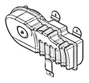
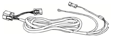
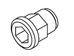
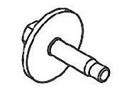
1 MY F150 CrewCab 1 Tools Required A B C D 3X E F G H 2X I 6X 3X Page 1 of 10 9L3J-19A014-AA Copyright Ford 2013 FoMoCo


. 6. Insert the subwoofer power harness terminals into the connector body.")
2 MY F150 CrewCab 2 Subwoofer Power Wire Routing All Vehicles WARNING: Battery cable stud is connected directly to the battery. Use caution to avoid allowing tools to touch chassis. Before routing the subwoofer power harness, you must first cut the plastic tie that is securing the connector body to the harness. Save the connector body for installation after the harness is routed into the cabin of the vehicle. 1. Open the cover to the Power Distribution Box (PDB) and remove the PDB battery cable nut. 2. Connect the ring terminal of the subwoofer power harness to the PDB battery cable stud and reinstall the PDB battery cable nut. 4. Make an X shaped incision the grommet at the point indicated. 5. Pass the subwoofer power harness into the cabin through the incision in the grommet. WARNING: It is critical that the PDB battery cable nut be tightened to the correct torque specification. Install the nut and tighten to 9Nm (80 lb-in). 6. Insert the subwoofer power harness terminals into the connector body. NOTICE: The black two pin connector has a block-out plug installed to insure the terminal is inserted in the correct cavity. 3. Route the subwoofer power harness from the PDB along the vehicle electrical harness and toward the rubber grommet in the metal dash panel on the passenger s side. Use supplied wire ties to secure the harnesses to the vehicle harness. Page 2 of 10 9L3J-19A014-AA Copyright Ford 2013 FoMoCo
 9. Remove the pin-type retainer from the cowl trim panel. 12. Pull upward to release the scuff plate clips and remove the RH rear door scuff plate.")

3 MY F150 CrewCab 3 Cowl Side Trim Panel Removal 7. Pull upward to release the scuff plate clips and remove the front door scuff plate. Detach the scuff plate from the weatherstrip. 8. Remove the fuse panel access door. 120 mm (5 in) 9. Remove the pin-type retainer from the cowl trim panel. 12. Pull upward to release the scuff plate clips and remove the RH rear door scuff plate. Detach the scuff plate from the weatherstrip. 13. Route the subwoofer harness along the factory electrical harness. Route under carpet and through the incision in the carpet. Pull the B pillar cover and rubber molding away far enough to allow the subwoofer body harness connector to pass. Use supplied wire ties to secure the harness to the vehicle harness. 10. Remove the cowl trim panel. Subwoofer Body Harness Routing 11. Measure 120mm (5 in) from the edge of the RH rear scuff plate and make a 50mm (2 in) incision Page 3 of 10 9L3J-19A014-AA Copyright Ford 2013 FoMoCo


4 MY F150 CrewCab Connect the subwoofer body harness (D) to the subwoofer power harness (B). Slide red connector lock to lock connectors. Refer to applicable wiring diagram for circuit information. For proper wire splicing techniques, click here. Subwoofer Body Harness Ground Connection 15. Remove the ground bolt below the glove compartment and connect the ground wire ring terminal of the subwoofer body harness to the ground bolt. Install the ground bolt and tighten to 9Nm (80 lb-in). Subwoofer Cabinet Installation 19. Set the enclosure in place and mark the three mounting holes. Make sure the enclosure is pushed firmly rearward against the hump in the floor pan. Center the two front mounting brackets in the recessed areas. Subwoofer Signal Input Connection 16. Find the harness indicated in the RH kick panel. Using a razor knife carefully cut through the sheathing of the harness indicated to find the twisted pair of wires that are white with a violet stripe and white with an orange stripe. 17. Connect the green wire of the 2-way adaptor harness (I) to the white/violet vehicle wire. Connect the brown wire of the 2-way adaptor harness (I) to the white/orange vehicle wire. 18. Connect the white 2-way adaptor harness (I) to the 2-way input connector of the subwoofer body harness (D). Page 4 of 10 9L3J-19A014-AA Copyright Ford 2013 FoMoCo


 chassis. 26. Turn the ACM on. 27. Operate the audio system in radio tuner AM/FM mode. 28.")
5 MY F150 CrewCab Using a razor knife, cut 38 mm (1.5 in) diameter hole in the carpet around each of the marks. 38 mm (1.5 in) 21. Install one of the supplied nut-inserts into each hole using the appropriate installation tool. 22. Connect the two subwoofer body harness connectors to the subwoofer connectors. Slide red connector locks to lock connectors. Install Trim Panels 24. Reverse steps to reinstall all previously removed parts. Refer to torque specification table. Install System Fuse 25. Install the supplied fuse into the power harness fuse holder. Audio Control Module (ACM) Self- Diagnostic Mode If the Audio Front Control Module (ACM), FCDIM (if equipped), FCIM, or FDIM (if equipped) are inoperative (blank or do not power on), obtain the ACM part number by referencing the label attached to the Audio Front Control Module (ACM) chassis. 26. Turn the ACM on. 27. Operate the audio system in radio tuner AM/FM mode. 28. Press and hold the eject button, and within 1 second, press the seek up button. If supported, the speaker walk around test will begin, and the display will indicate each speaker as it is tested. AHU Diagnostics refers to the Audio Front Control Module (ACM), EFP Diagnostics refers to the FCIM, and MFD Diagnostics (if supported) refers to the FCDIM (if equipped). 29. To exit the self-diagnostic mode, turn the Audio Front Control Module (ACM) off, or select "Exit Diagnostics." 23. Bolt subwoofer in place using the three supplied bolts. Tighten to 9Nm (80 lb-in). Install the supplied bolt covers (J). Page 5 of 10 9L3J-19A014-AA Copyright Ford 2013 FoMoCo
6 MY F150 CrewCab 6 Trouble Shooting Guide Symptom Possible Cause Solution Fuse not installed Install fuse into fuse in inline fuse holder. (Refer to holder instructions) No Subwoofer Output Low battery voltage Ground wire not grounded properly Balance or Fader controls not set to neutral position No low frequency information in music Subwoofer body harness not properly connected. Splicing Procedures Recharge the battery. (Refer to Vehicle Owner s Manual) Check ground wire with ohm meter to insure a positive ground. Set balance and fader controls to center settings. Test system with several samples of music. Check subwoofer body harness signal input and power input connectors to ensure all connectors are completely engaged. Refer to applicable wiring diagrams for circuit information. This procedure contains multiple splicing techniques. Review splicing procedures prior to performing any cutting/soldering/splicing. 2-Wire Solder "Center Splice" With No Wire Cutting Follow this procedure when a wire can be spliced without cutting the wire in half. 1. Strip approximately two inches of insulation from the wire to be installed in the vehicle. 2. On the vehicle wire to be spliced into, strip one inch of insulation from the wire. 3. On the vehicle wire to be spliced into, separate the strands to allow the new wire to be placed. 4. Insert the new wire between the parted strands. If more than one wire is being spliced, wrap them in opposite directions. Page 6 of 10 9L3J-19A014-AA Copyright Ford 2013 FoMoCo
7 MY F150 CrewCab 7 Use Rosin Core Mildly-Activated (RMA) Solder. Do not use Acid Core Solder. Wait for solder to cool before moving wires. 5. Wrap the new wire around one side of the split strands, then wrap it around the other side. Solder the connections 2-Wire Solder Splice/Ratcheting Crimp Tool Splice Procedure For AWG Use the following "Ratcheting Crimp Tool Splice Procedure". For splicing procedure use wire splice tool kit (164- R5903). 7. The strip length will vary depending on the butt splice and wire in harness. Longer strip lengths are required when the wire needs to be folded to mate with the butt splice. Refer to chart for strip lengths and folding techniques. Strip 114" (6.35 mm) of insulation from pigtail wire end once the wire lengths are sized so repairs can be staggered. Take care not to nick or cut wire strands. Pull wire straight from stripper. If wire is pulled at an angle, wire strands may be cut off. If more than one (1) strand is cut off during stripping, cut off the end and restrip. Slide heat shrink tubing onto one (1) of the wire ends to be crimped, must be at least 1" (25.4mm) away from the stripped end. 6. Wrap the connection with electrical tape so the tape covers the wires approximately two inches on either side of the connection. Tape the wires together as shown in the illustration. 8. Identify the appropriate crimping chamber of the Rotunda 164-R5901 Pro-Crimper (or equivalent) by matching the wire size on the dies with the wire size stamped on the butt splice. Hold the crimping tool so the identified wire sizes are facing you. Squeeze tool handles together until the ratchet releases, then allow the jaws of the tool to open fully. Page 7 of 10 9L3J-19A014-AA Copyright Ford 2013 FoMoCo
8 MY F150 CrewCab 8 9. Center one (1) end of the butt splice on the appropriate crimping chamber. If visible, be sure to place the brazed seam of the butt splice toward the indenter. Hold the butt splice in place and squeeze the tool handles together until the ratchet engages sufficiently to hold the butt splice in position (typically one (1) or two (2) clicks). DO NOT deform the butt splice. Insert stripped wire into the butt splice, making sure the insulation on wire does not enter the butt splice. 11. Overlap heat shrink tubing on both wires. The hot melt forms an adhesive seal between the wire insulation and the heat shrink tubing, which prevents air and moisture from entering the solder point. Durability of a heat shrink tubing splice is dependent on the hot melt that will appear from both ends of the tube. Evenly position heat shrink tubing over wire repair. Use a shielded heat gun to heat the entire length of the heat shrink tubing until the hot melt appears from both ends of the tubing. 10. Holding the wire in place, squeeze tool handles together until ratchet releases. Allow tool handles to open, then remove crimped butt splice. To crimp the other half of the splice, reposition the un-crimped wire barrel in the same crimping chamber, and repeat the crimping procedure. If splice cannot be turned for crimping the other half, turn the tool around. Check for acceptable crimp. Crimp should be centered on each end of the butt splice. It is acceptable for crimp to be slightly off center, but not off the end of the butt splice (A). Wire insulation does not enter butt splice. Wire is flush with or extends slightly beyond end of butt splice (B). Wire is visible through inspection hole of splices (C). Page 8 of 10 9L3J-19A014-AA Copyright Ford 2013 FoMoCo
9 MY F150 CrewCab 9 Wire Stripping Lengths and Application Techniques. For AWG wire use either the above "Ratcheting Crimp Procedure" or the following "2 Wire Solder Splice Procedure". 12. Strip I I/2" (37.2 mm) of insulation from Wire #I and 3/4" (I9.Smm) of insulation from Wire #2, taking care not to nick or cut wire strands. Pull wire straight from stripper. If wire is pulled at an angle, wire strands may be cut off during stripping. Cut off the end and restrip. 13. Use rosin core mildly activated (RMS) solder. do not use acid core solder for wire repair. Overlap tubing on both wires and wait for solder to cool before moving the wires. Durability of a heat shrink tubing splice is dependent on the hot melt that will appear from both ends of the tube. The hot melt forms an adhesive seal between the wire insulation and the heat shrink tubing, which prevents air and moisture from entering the solder point. Install heat shrink tubing at least 1" (26 mm) away from one of the stripped ends being spliced. Twist the wires together. Solder wires together. Bend Wire #1 back in a straight line for sealing. Inspect solder joint bond. Evenly position heat shrink tubing over wire repair. Use a shielded heat gun to heat the entire length of the heat shrink tubing until the hot melt appears from both ends of the tubing. Page 9 of 10 9L3J-19A014-AA Copyright Ford 2013 FoMoCo
10 MY F150 CrewCab 10 3-Wire Solder Splice Procedure 14. Strip 1 1/2" (37.2 mm) of insulation from both sides of Wire #1 and 3/4" (19 mm) of insulation from Wire #2, taking care not to nick or cut wire strands. Pull wire straight from stripper. If wire is pulled at an angle, wire strands may be cut off during stripping. Cut off the end and re-strip. 17. Evenly position heat shrink tubing over wire repair. 18. Durability of a heat shrink tubing splice is dependent on the hot melt that will appear from both ends of the tube. 15. Wait for solder to cool before moving wires. Apply heat shrink tubing to Wire #2. Twist both ends of Wire #1 around Wire #2. Solder wires together. The hot melt forms an adhesive seal between the wire insulation and the heat shrink tubing, which prevents air and moisture from entering the solder point. Use a shielded heat gun to heat the entire length of the heat shrink tubing until the hot melt appears from both ends of the tubing. 16. Bend Wire #1 back over the twisted wires for sealing. Inspect solder joint bond. Page 10 of 10 9L3J-19A014-AA Copyright Ford 2013 FoMoCo
MY F150 SuperCab 1. Tools Required. Page 1 of 12 9L3J-19A014-BA Copyright Ford 2013 FoMoCo
 2009-2014MY F150 SuperCab 1 Tools Required A B C D E F G 3X 6X 3X H I J 2X 3X 3X K L M N 3X Page 1 of 12 9L3J-19A014-BA Copyright Ford 2013 FoMoCo 2009-2014MY F150 SuperCab 2 Subwoofer Power Wire Routing
MY F150 CrewCab 1. Tools Required 10X. Page 1 of 15 DL3J-19A014-AA Copyright Ford 2013 FoMoCo
 2013-2014MY F150 CrewCab 1 Tools Required A B C D E F G 4X H I J K 3X L 3X 2X 10X 2X Page 1 of 15 DL3J-19A014-AA Copyright Ford 2013 FoMoCo 2013-2014MY F150 CrewCab 2 Vehicles with selector lever in floor
Splicing Procedures 4. 2 Insert the new wire between the parted strands. If more than one wire is being spliced, wrap them in opposite directions. Use
 Splicing Procedures 1 Splicing Procedures Refer to applicable wiring diagrams for circuit information. This procedure contains multiple splicing techniques. Review splicing procedures prior to performing
Designed for 2014 and newer 1500 Series and 2015 and newer Heavy Duty GM Silverado/Sierra Double Cab vehicles
 19303116 Designed for 2014 and newer 1500 Series and 2015 and newer Heavy Duty GM Silverado/Sierra Double Cab vehicles Subwoofer Assembly Subwoofer Body Harness 25A Fuse Wire Ties x 6 Wire Taps x 2 Adapter
SF150C09. Designed for Ford F150 Super-Crew vehicles (not compatible with trucks that have Sony Factory Premium Audio) Subwoofer Assembly
 Subwoofer Assembly") SF150C09 Designed for 2009-2014 Ford F150 Super-Crew vehicles (not compatible with trucks that have Sony Factory Premium Audio) Subwoofer Assembly Subwoofer Power Harness Subwoofer Body Harness M6 Bolts
SF150C09 Designed for 2009-2014 Ford F150 Super-Crew vehicles (not compatible with trucks that have Sony Factory Premium Audio) Subwoofer Assembly Subwoofer Power Harness Subwoofer Body Harness M6 Bolts
Designed for 2015 Ford F150 Super-Cab and Super-Crew vehicles (Compatible in vehicles with or without Sony System. M6 Bolt X 2
 SF150SC15 Designed for 2015 Ford F150 Super-Cab and Super-Crew vehicles (Compatible in vehicles with or without Sony System Subwoofer Assembly Amplifier Relocation Bracket (not used on non Sony trucks)
Designed for 2005 & newer Ford Mustang (Not compatible with Convertible)
") Designed for 2005 & newer Ford Mustang (Not compatible with Convertible) SMUS05 Subwoofer Enclosure Assembly Power Harness Body Harness Input Adapter Wire Ties x6 M6 Nut 25A Fuse Wire Taps x2 SMUS05 A.2
Designed for 2005 & newer Ford Mustang (Not compatible with Convertible) SMUS05 Subwoofer Enclosure Assembly Power Harness Body Harness Input Adapter Wire Ties x6 M6 Nut 25A Fuse Wire Taps x2 SMUS05 A.2
SSICRE14. Subwoofer Assembly. Subwoofer Body Harness. Subwoofer Power Harness. Fuse Wire Ties x 6 Wire Taps x 2 Adaptor Harness
 SSICRE14 Designed for: 2014 and newer Chevrolet Silverado & GMC Sierra Crew-Cab 1500 series with base or premium radio 2015 and newer Chevrolet Silverado & GMC Sierra Crew-Cab 2500/3500 with base or premium
PROCEDURE STEPS: WARNING:
 WI-FI ROUTER 1 DODGE NITRO, JEEP LIBERTY PROCEDURE STEPS: WARNING: Disable the airbag system before attempting any steering wheel, steering column, or instrument panel component diagnosis or service. Disconnect
SFSDC08. Designed for 2008-present Ford F250/F350 Super Crew vehicles. Adaptor Harness. Subwoofer Power Harness
 SFSDC08 Designed for 2008-present Ford F250/F350 Super Crew vehicles Subwoofer Enclosure Subwoofer Harness Adaptor Harness Wire Ties Wire Taps Fuse Factory Amplifier Relocation Bracket, Nut and Bolt Subwoofer
SWRA211. T-TAP x2 10MM BOLT FUSE WIRE TIES x6 SUBWOOFER ASSEMBLY 200 WATT AMP BRACKET ASSEMBLY POWER HARNESS OVERLAY HARNESS.
 SWRA211 Designed for 2011-2014 Jeep Wrangler two door with base audio or premium audio T-TAP x2 10MM BOLT FUSE WIRE TIES x6 SUBWOOFER ASSEMBLY 200 WATT AMP BRACKET ASSEMBLY POWER HARNESS 2012 Stillwater
PF150SC15. Designed for 2015 and newer Ford F150 Super-Cab and Super-Crew vehicles without Sony System Stillwater Designs PF150SC15-A
 PF150SC15 Designed for 2015 and newer Ford F150 Super-Cab and Super-Crew vehicles without Sony System Subwoofer Assembly Amplifier Assembly Amplifier Harness 2015 Stillwater Designs PF150SC15-A2-20160502
PFSDC12. Designed for 2012 and newer Ford F250/F350 Super Crew vehicles Stillwater Designs PFSDC12-A Subwoofer Enclosure
 PFSDC12 Designed for 2012 and newer Ford F250/F350 Super Crew vehicles Subwoofer Enclosure Amplifier/Bracket Assembly Subwoofer Power Harness Amplifier Harness Subwoofer Harness Amplifier Power Harness
SSUTAYU15. Designed for 2015 and newer Chevrolet Tahoe/Suburban and GMC Yukon/Yukon XL vehicles
 SSUTAYU15 Designed for 2015 and newer Chevrolet Tahoe/Suburban and GMC Yukon/Yukon XL vehicles Subwoofer Assembly Subwoofer Harness Subwoofer Power Harness 2018 Stillwater Designs SSUTAYU15-20180313 Wire
PSIEXT16I. Designed for 2016 and newer 1500 Series and Heavy Duty GM Silverado/Sierra Double Cab vehicles with 7 inch touchscreen radio
 PSIEXT16I Designed for 2016 and newer 1500 Series and Heavy Duty GM Silverado/Sierra Double Cab vehicles with 7 inch touchscreen radio Not compatible with Bose Audio Not compatible with 4.2 inch radio
SRAMCQ09. Designed for Dodge Ram vehicles Stillwater Designs SRAMCQ Subwoofer. Subwoofer Harness.
 SRAMCQ09 Designed for 2009-2018 Dodge Ram vehicles Subwoofer Alternate Amp Bracket Subwoofer Harness Subwoofer Amplifier Wire Ties x 6 Adapter Harness Subwoofer Power Harness Bolt (only for solid rear
Fitting Instructions
 Reverse Park Assist Suitable for: Nissan Navara Kit Part No: 5466XX NP00 Tow-Pro Wiring Kit Fitting Instructions Accessory Kit Estimated Fitting Time: 0 Minutes FI98 Page 0 of 5 General Notes Read through
PWRA215. Designed for 2015 and newer Jeep Wrangler two door with base audio. T-TAP x2 10MM BOLT FUSE WIRE TIES x6 SUBWOOFER ASSEMBLY
 PWRA215 Designed for 2015 and newer Jeep Wrangler two door with base audio T-TAP x2 10MM BOLT FUSE WIRE TIES x6 SUBWOOFER ASSEMBLY 200 WATT AMP BRACKET ASSEMBLY POWER HARNESS 2015 Stillwater Designs PWRA215
PSIEXT14. Subwoofer Assembly. Subwoofer Power Harness. Subwoofer Body Harness. 25A Fuse Wire Ties x 6 Washers x 2
 PSIEXT14 Designed for 2014 and newer Chevrolet Silverado & GMC Sierra Double-Cab 1500 series with base radio 2015 and newer Chevrolet Silverado & GMC Sierra Double-Cab 2500/3500 with base radio (Not compatible
PSICRE14. Subwoofer Assembly. Subwoofer Power Harness. Subwoofer Body Harness 25A Fuse Wire Ties x Stillwater Designs PSICRE14-A
 PSICRE14 Designed for 2014 and newer Chevrolet Silverado & GMC Sierra Crew-Cab 1500 series with base radio 2015 and newer Chevrolet Silverado & GMC Sierra Crew-Cab 2500/3500 with base radio (Not compatible
Accessory Kit Estimated Fitting Time: 120 Minutes (Prado) Estimated Fitting Time: 140 Minutes (Kluger)
 Estimated Fitting Time: 140 Minutes (Kluger)") Tow-Pro Wiring Kit - Toyota Kluger / Prado Accessory Kit Estimated Fitting Time: 0 Minutes (Prado) Estimated Fitting Time: 0 Minutes (Kluger) FI99 Page 0 of Issue: Date: 0/0/0 0 General Notes Read through
Tow-Pro Wiring Kit - Toyota Kluger / Prado Accessory Kit Estimated Fitting Time: 0 Minutes (Prado) Estimated Fitting Time: 0 Minutes (Kluger) FI99 Page 0 of Issue: Date: 0/0/0 0 General Notes Read through
Fitting Instructions
 Tow-Pro Wiring Kit Fitting Instructions Holder Colorado / Colorado 7 Accessory Kit Estimated Fitting Time: 0 Minutes FI7 Page 0 of General Notes Read through the fitting instructions before installation
PRAMCQ13. Designed for Dodge Ram vehicles with base audio Not Compatible with 2018 and newer Dodge Ram vehicles
 PRAMCQ13 Designed for 2013 2017 Dodge Ram vehicles with base audio Not Compatible with 2018 and newer Dodge Ram vehicles Subwoofer Alternate Amplifier Bracket Amplifier Subwoofer Harness Subwoofer Amplifier
SCAMA10. Designed for Chevrolet Camaro vehicles. Subwoofer Assembly. Subwoofer Bracket Wire Ties x6 Wire Taps x2 Rubber Bumper
 SCAMA10 Designed for 2010-2015 Chevrolet Camaro vehicles Subwoofer Assembly Subwoofer Harness Subwoofer Bracket Wire Ties x6 Wire Taps x2 Rubber Bumper 2012 Stillwater Designs SCAMA10-A3-20151028 M6 Nut
Fitting Instructions
 Tow-Pro Wiring Kit Fitting Instructions Suitable for: Toyota Hilux / Fortuner Accessory Kit Estimated Fitting Time: 90 Minutes FI807 Page 0 of Issue: Date: /08/08 08 General Notes Safety Notes Suitable
Accessory Kit Estimated Fitting Time: 120 Minutes
 Landcruiser LC00 Tow-Pro Wiring Kit - Landcruiser LC00 Kit Part No: TPWKIT - 005 Accessory Kit Estimated Fitting Time: 0 Minutes FI88 Page 0 of Issue: Date: 7/09/07 07 General Notes Safety Notes Parts
Configuration and Programming 1
 Configuration and Programming 1 GENERAL PROCEDURES Superseded by:sgml_id= n1132613 7. From the technician service publication site Effect:Frozen: N 2009 MIKETEST 19 020 (PTS), run OASIS using Quick Start.
PCAMA13MY. Designed for Chevrolet Camaro vehicles with MyLink. Subwoofer Assembly. Subwoofer Bracket Wire Ties x6 Rubber Bumper
 PCAMA13MY Designed for 2013-2015 Chevrolet Camaro vehicles with MyLink Subwoofer Assembly Subwoofer Harness Adapter Harness Subwoofer Bracket Wire Ties x6 Rubber Bumper 2012 Stillwater Designs PCAMA13MY-A3-20151028
1999 Dodge or Ram Truck RAM 1500 Truck 2WD V8-5.9L VIN Z LDC
 ALLDATA Repair - 1999 Dodge or Ram Truck RAM 1500 Truck 2WD V8-5.9L VIN Z... Page 1 of 10 1999 Dodge or Ram Truck RAM 1500 Truck 2WD V8-5.9L VIN Z LDC Vehicle» Instrument Panel, Gauges and Warning Indicators»
GENUINE PARTS INSTALLATION INSTRUCTIONS
 GENUINE PARTS INSTALLATION INSTRUCTIONS 1. 2. 3. 4. DESCRIPTION: Illuminated Kick Plate Kit APPLICATION: Murano PART NUMBER: 999G6 C2000, 999G6 C2100, 999G6 C2200 999Q9 AY001 - Accessory Service Connector
SCHAL08. Designed for Dodge Challenger vehicles. Subwoofer Assembly. 200W Amplifi er. Wire Harness
 SCHAL08 Designed for 2008-2014 Dodge Challenger vehicles Subwoofer Assembly 200W Amplifi er Wire Harness 2012 Stillwater Designs SCHAL08-A3-20140930 Wire Ties x6 25A Fuse #8 Sheet Metal Screws x4 Body
M GT 2005 up Mustang ENGINE START Push-Button INSTRUCTION SHEET
 Please contact the Ford Racing Techline for the most current instruction information @ (800) FORD-788!!! PLEASE READ THE FOLLOWING INSTRUCTIONS CAREFULLY PRIOR TO INSTALLATION!!! OVERVIEW: The following
Terminal Tractor Service Bulletin Subject: Forward Facing Flood Lights w/ LED Light Bar Field Rewire Modification Product: Medium Terminal Tractor
 Page 1 of 6 Units Affected: FedEx Ground Kalmar Ottawa T2 terminal tractors built between chassis serial numbers; 346358 and 346471. Possible Situation: The fuse holder is melting due to high current demand
Fitting Instructions
 Reverse Park Assist Suitable for: Isuzu MU-X Kit Part No: / 5466XX D-Max Tow-Pro Wiring Kit Fitting Instructions Suitable for: Isuzu MU-X / D-Max Accessory Kit Estimated Fitting Time: 0 Minutes FI967 Page
INSTALLATION INSTRUCTIONS
 Rear Vision System Liftgate Emblem Camera Mirror Display 2009-2012 Ford Flex (Kit part number 1008-9527) Kit Contents: Mirror Liftgate Emblem Mount with Camera Interior (shorter) Harness Chassis (longer)
RAV4 TNS310 (Traffic) Plus
 Plus") TNS310 (Traffic) Plus RHD installation instructions Model year: 005 Vehicle code: **A3***-*****W Part number TNS310 Plus: Sub wire harness No 1: 08673-64801 Sub wire harness No : 08673-64800 Part number
TNS310 (Traffic) Plus RHD installation instructions Model year: 005 Vehicle code: **A3***-*****W Part number TNS310 Plus: Sub wire harness No 1: 08673-64801 Sub wire harness No : 08673-64800 Part number
CONTENTS TOOLS REQUIRED: *Ratchet*13mm Socket*10mm Socket*Phillips Screwdriver*Pliers*Panel Removal Tool. Subwoofer Installation
 CONTENTS 1EA. SUBWOOFER ASSEMBLY P/N 77KICK40SUBASSEMBLY 1EA. 200 WATT AMP P/N RE08BTL2000R 1EA. POWER HARNESS P/N RHWRANGLERPWR 1EA. OVERLAY HARNESS P/N RHWRANGLER 2EA. T-TAP P/N RFTTAPB 1EA. FUSE 30
Contents. TCS/ Driver Mod Installation Manual
 Contents Introduction... 1 TCS Packing List... 3 Tools Needed for Installation... 4 How to Properly Solder... 5 Soldering Standard Butt Connection... 5 Soldering T Connection... 6 How to Properly Crimp...
System Date of Issue Bulletin Number Bulletin Type. Title: Elimination of AC Connectors J29a and J29b
 System Date of Issue Bulletin Number Bulletin Type Odyne System G2V2 2/4/15 Rev. 10/6/15 00020 Field Service Action Technical Service Bulletin Technical Service Advisory Title: Elimination of AC Connectors
SPEED CONTROL 4 AND 6 CYL. JEEP WRANGLER. Read entire instructions thoroughly before starting. INSTALLATION INSTRUCTIONS TOOLS REQUIRED:
 Read entire instructions thoroughly before starting. TOOLS REQUIRED: SPEED CONTROL 4 AND 6 CYL. JEEP WRANGLER INSTALLATION INSTRUCTIONS Complete socket set Phillips screwdriver Torx drivers Wire strippers/cutters
GENUINE PARTS INSTALLATION INSTRUCTIONS
 GENUINE PARTS INSTALLATION INSTRUCTIONS 1. 2. 3. 4. DESCRIPTION: Security Light Kit APPLICATION: Altima Coupe and Sedan (2011+) PART NUMBER: 999F4 AX008 - Universal Security Lighting Kit. KIT CONTENTS:
TOYOTA VENZA 2009 TRAILER WIRE HARNESS Procedure
 Part Number: PT791-0T099 Kit Contents Item # Quantity Reqd. Description 1 1 Trailer Wire Harness Module 2 1 4-Flat Harness 3 1 Battery Power Wire Harness 4 1 Mounting Bracket, 4-Flat 5 2 Screw #10-24 6
* * Inside Toyota Avalon. Tools Required IMPORTANT
 Revision 08/02/16 2013- Toyota Avalon IMPORTANT Before starting, compare items on your invoice with items received. Carefully check through packaging material. If any item is missing, please call Crutchfield
INSTALLATION INSTRUCTIONS
 Rear Vision System Tailgate Emblem Camera Mirror Display 2009-Current Ford F-150 and 2010-Current Super Duty (Kit part number 1008-9527) Kit Contents: Mirror Tailgate Emblem Mount with Camera Interior
SALEEN SPEEDLAB BOOST AND WATER TEMPERATURE GAUGE POD KIT
 = SALEEN SPEEDLAB BOOST AND WATER TEMPERATURE GAUGE POD KIT INSTALLATION MANUAL: 2005-09 Mustang 4.6L 3V P/N: 10-8002-C12000B KIT P/N: 10-2903-B11511* Saleen Performance, Inc. 1225 East Maple Rd. Troy,
EMK-XP ElectroMelt Power Connection and End Seal Kit Installation Instructions
 EMK-XP ElectroMelt Power Connection and End Seal Kit Installation Instructions Description The ElectroMelt EMK-XP Power Connection and End Seal Kit is for use with ElectroMelt EM2-XR and EM3-XR heating
GENUINE PARTS INSTALLATION INSTRUCTIONS
 GENUINE PARTS DESCRIPTION: APPLICATION: PART NUMBER: REQUIRED FOR INSTALLATION: INSTALLATION INSTRUCTIONS Interior Accent Lighting Kit. Murano 999F3 C5000 999Q9 AY001 (Accessory Service Connector) -Not
650 Series Cargo Van Lift Mounting Instructions Fullsize Ford 1992-Present
 TOMMY GATE OWNER'S / OPERATOR'S MANUAL 650 Series 650 LB Capacity 650 Series Cargo Van Lift Mounting Instructions Fullsize Ford 1992-Present Installing the Base Plate 1. Examine the interior and exterior
Installation instructions, accessories. Subwoofer
 Installation instructions, accessories Instruction No 9162298 Version 1.0 5 Part. No. Subwoofer Volvo Car Corporation Subwoofer - 9162298 - V1.0 Page 1 / 24 Equipment A0000162 A0801178 A0000161 R8802817
Installation Instructions
 Installation Instructions Jeep JK 2-Door (2011 Present) Mounting Bracket and Air Line System Kit for ARB On-Board Twin Air Compressor (CKMTA12) Made in the USA Kit Contents: 1 Flat Bracket 1 Formed Bracket
CONTENTS TOOLS REQUIRED:
 CONTENTS 1EA. FIVE CHANNEL AMPLIFIER P/N MPDSP033AA 1EA. AMPLIFIER BRACKET P/N RM11JK41 1EA. POWER HARNESS P/N RH41JKP 1EA. OVERLAY HARNESS P/N RH41JK 1EA. FUSE 30 AMP P/N RFUSE30 6EA. WIRE TIE P/N RFZIP6
GENUINE PARTS INSTALLATION INSTRUCTIONS
 GENUINE PARTS INSTALLATION INSTRUCTIONS DESCRIPTION: APPLICATION: PART NUMBER(S) REQUIRED FOR INSTALLATION: Dual Rear Seat USB Charge Port Kit Titan T99Q7 6LB0A (Excluding Single Ca T98Q7 5ZW2A (Metal
INSTALLATION INSTRUCTIONS TRAILER HITCH MAIN HARNESS KIT
 PART NUMBER: 0000-89-N30 GENUINE ACCESSORIES INSTALLATION INSTRUCTIONS TRAILER HITCH MAIN HARNESS KIT APPLICABLE MODELS: 2016 > CX-9 PACKAGE CONTENTS: INSTALLATION INSTRUCTIONS QTY 1 CABLE TIE MOUNT QTY
CONTENTS TOOLS REQUIRED: *Ratchet*13mm Socket*10mm Socket*Phillips Screwdriver*Pliers*Panel Removal Tool. Subwoofer Installation
 CONTENTS 1EA. SUBWOOFER ASSEMBLY P/N 77KICK24SUBASSEMBLY 1EA. 200 WATT AMP P/N RE08BTL200R 1EA. POWER HARNESS P/N RHWRANGLERPWR 1EA. OVERLAY HARNESS P/N RHWRANGLER 2EA. T-TAP P/N RFTTAPB 1EA. FUSE 30 AMP
Installation Instructions - ECS Tuning Vent Pod Vacuum/Boost Gauge Kit
 Installation Instructions - ECS Tuning Vent Pod Vacuum/Boost Gauge Kit This tutorial is provided as a courtesy by ECS Tuning. Part Number for (2005-2008) Proper service and repair procedures are vital
UNSIGNED HARDCOPY NOT CONTROLLED
 Subject: APPROVED BY STATUS PURPOSE AFFECTED FUNCTIONS Flat Braid Cables Manager, Hardware Engineering Maintenance Revision Establishes the requirements for the fabrication of special-purpose electrical
AUXILIARY BATTERY BOX INSTALLATION INSTRUCTIONS
 AUXILIARY BATTERY BOX INSTALLATION INSTRUCTIONS The original TOMMY GATE hydraulic lift Assembling the Auxiliary Battery Box 1. Remove the cover from the auxiliary battery box by removing the two nuts and
INSTALLATION INSTRUCTIONS
 Rear Vision System Tailgate Emblem Camera Aftermarket Display 2009-Current Ford F-150 and 2010-Current Super Duty (Kit part number 1008-6509) Kit Contents: Tailgate Emblem Mount with Camera Chassis Harness
INSTALLATION INSTRUCTIONS
 Rear Vision System Tailgate Handle Camera Mirror Display 2004-2014 Ford F-150 and 2008-2015 Ford Super Duty (Kit part numbers 9002-9521) Kit Contents: Mirror Tailgate Handle with camera and harness Interior
2005+ Mustang Trunk Lid Release and Trunk Lights Installation
 There is no warranty expressed or implied by this document, you follow these instructions at your own risk. These instructions worked for me, but your experience may vary. The final product of these instructions
TOYOTA LAND CRUISER 2003 DVD VES
 LEXUS LX470 Section I Installation Preparation Part Number: PT296 6002D 03/16 (LC) PT296 6002L 03/16 (LX) Section I Installation Preparation Kit Contents Item # Quantity Reqd. Description 1 1 FPD Assembly
Installation of Auto Meter Cobalt Boost/Vacuum Gauge:
 Installation of Auto Meter Cobalt Boost/Vacuum Gauge: Fitment: All 79-14 models. This installation was completed on a 2004 Mustang GT, and should be identical for all 1999-2004 model Mustangs. Time needed:
Rear Vision System Liftgate Emblem Camera for Aftermarket Display Ford Flex (Kit part number )
") Rear Vision System Liftgate Emblem Camera for Aftermarket Display 2009-2012 Ford Flex (Kit part number 1008-6509) Kit Contents: Liftgate Emblem Mount with Camera Chassis Harness with RCA (Note: In some
Rear Vision System Liftgate Emblem Camera for Aftermarket Display 2009-2012 Ford Flex (Kit part number 1008-6509) Kit Contents: Liftgate Emblem Mount with Camera Chassis Harness with RCA (Note: In some
TOYOTA VENZA HANDS FREE BLU LOGIC Preparation
 TOYOTA VENZA 2009- HANDS FREE BLU LOGIC Preparation Part #: PT923-00111 Conflicts: JBL Audio NOTE: Part number of this accessory may not be the same as the part number shown. Kit Contents: For kits manufactured
SCION xa 2004 SATELLITE RADIO TUNER Section I Installation Preparation
 Section I Installation Preparation Part Number: PT546 52040 Section I Installation Preparation Kit Contents Item # Quantity Reqd. Description 1 1 Satellite Tuner 2 1 Ground Cable 3 1 Tuner Cable 4 2 Tuner
29048, 29049, 29050, 29051, 29052, 29053, 29054,
 April 15, 2014 Lit. No. 29225, Rev. 11 29048, 29049, 29050, 29051, 29052, 29053, 29054, 29400 5 HARNESS KIT 3 PORT ISOLATION MODULE LIGHT SYSTEM w/2 PLUG SYSTEM HARNESSES Installation Instructions Read
GENUINE PARTS INSTALLATION INSTRUCTIONS
 GENUINE PARTS INSTALLATION INSTRUCTIONS DESCRIPTION: APPLICATION: PART NUMBER(S) REQUIRED FOR INSTALLATION: KIT CONTENTS: WiFi Sentra T99Q8 4RA0A (Wifi kit) 999Q9-AY000 (Accessory Service Connector) -
General Applicability Note: Recommended Tools. Personal & Vehicle Protection Safety Goggles Seat Covers Floor Covers Special Tools. Installation Tools
 TOYOTA HIGHLANDER/HIGHLANDER HV 2008- Preparation Part #: PT923-00111 Conflicts: JBL Audio, Factory Navigation NOTE: Part number of this accessory may not be the same as the part number shown. Kit Contents:
INSTALLATION INSTRUCTIONS
 INSTALLATION INSTRUCTIONS Accessory Application Publications No. 2004 S2000 AII 26323-31611 Issue Date DEC 2005 PARTS LIST Rear defroster switch Hardtop 3-Pin subharness (If equipped, not used) 4-Pin subharness
IT IS IMPORTANT THAT YOU OBTAIN THE CORRECT INFORMATION FOR YOUR VEHICLE, OR DAMAGE TO THE WIRING SYSTEM COULD OCCUR.
 Instructions for Universal Harness PRINT THESE INSTUCTIONS Gentex Mirror Installation Instructions Provided by www.rearviewautomirrors.com These instructions have been prepared to provide you with details
LiteDOT Installation Document
 LiteDOT Installation Document This document designed to aid in installation of LiteDOT s on Jeep TJ models, other models are similar. NOTE: Installing LiteDOT s on a Jeep where the 2 necessary mounting
INSTALLATION INSTRUCTIONS
 INSTALLATION INSTRUCTIONS Accessory Application Publications No. SYSTEM ACCORD 2-DOOR (LX/EX L4, LX V6) AII 25749 Issue Date FEB 2004 PARTS LIST Double-sided adhesive tape XM Radio Attachment Kit : P/N
CONTENTS: 1EA. SUBWOOFER HARNESS 2PIECE TOOLS REQUIRED:
 CONTENTS: 1EA. SUBWOOFER ENCLOSURE 1EA. SUBWOOFER HARNESS 2PIECE 2EA. T-TAP 1EA. FUSE 30 AMP 6EA. WIRE TIES 1EA. INSTRUCTIONS P/N 77KICK14SUBASSEMBLY P/N RHPM1 P/N RFTTAPB P/N RFUSE30 P/N RFZIP6 P/N RBI77KICK14
GENUINE PARTS INSTALLATION INSTRUCTIONS
 GENUINE PARTS INSTALLATION INSTRUCTIONS 1. 2. 3. 4. DESCRIPTION: APPLICATION: PART NUMBER: KIT CONTENTS: Security light Kit Maxima 999F4 AX009 - Universal Security Lighting Kit. Item QTY Description Service
650 Series Cargo Van Lift Mounting Instructions Ford Transit (Standard Roof) 2015-Present
 2015-Present") TOMMY GATE OWNER'S / OPERATOR'S MANUAL 650 Series 650 LB Capacity 650 Series Cargo Van Lift Mounting Instructions Ford Transit (Standard Roof) 2015-Present Installing the Base Plate 1. Examine the interior
TOMMY GATE OWNER'S / OPERATOR'S MANUAL 650 Series 650 LB Capacity 650 Series Cargo Van Lift Mounting Instructions Ford Transit (Standard Roof) 2015-Present Installing the Base Plate 1. Examine the interior
PART NUMBER: H630SSJ000. Kit Contents: A. Amplifier with Bracket (1) D. Badge (2) with push nuts (4)
 D. Badge (2) with push nuts (4)") Kit Contents: A. Amplifier with Bracket (1) D. Badge (2) with push nuts (4) E. Clip B. Harness (1) C. Cable tie (8) F. Mounting Hardware (2) G. Replacement Speaker (2) H. HVAC Duct extension (2) IMPORTANT:
Kit Contents: A. Amplifier with Bracket (1) D. Badge (2) with push nuts (4) E. Clip B. Harness (1) C. Cable tie (8) F. Mounting Hardware (2) G. Replacement Speaker (2) H. HVAC Duct extension (2) IMPORTANT:
LEXUS RC 350/RC-F ILLUMINATED DOOR SILLS Preparation
 Preparation Part Number: PT944-24150 Kit Contents Item # Quantity Reqd. Description 1 2 Inner LED Scuff 2 2 Outer Scuff 3 1 Hardware Bag Hardware Bag Contents Item # Quantity Reqd. Description 1 15 20
GENUINE PARTS INSTALLATION INSTRUCTIONS
 GENUINE PARTS INSTALLATION INSTRUCTIONS DESCRIPTION: APPLICATION: PART NUMBER(S) REQUIRED FOR INSTALLATION: KIT CONTENTS: Wireless Charging Kit Maxima 999F7 V4000 999Q9-AY001 (Accessory Service Connector)
TOYOTA VENZA 2009 TRAILER WIRE HARNESS Procedure
 Part Number: PT791-0T099 Kit Contents Item # Quantity Reqd. Description 1 1 Trailer Wire Harness Module 2 1 4-Flat Harness 3 1 Battery Power Wire Harness 4 1 Mounting Bracket, 4-Flat 5 2 Screw #10-24 6
29048, 29049, 29050, 29051, 29052, 20953, 29054,
 July 15, 2008 Lit. No. 29225, Rev. 06 29048, 29049, 29050, 29051, 29052, 20953, 29054, 29400-2 HARNESS KIT 3-PORT ISOLATION MODULE LIGHT SYSTEM w/2-plug SYSTEM HARNESSES Installation Instructions Read
Cantilever Series Mounting Instructions Fullsize Sprinter Van (US) All except WB (AA) present
 All except WB (AA) present") Fullsize Sprinter Van (US) All except 3500 144 WB (AA)- 2007-present Preparing the Gate 1. Remove the platform, mounting kit, license plate assembly, and bridge assemblies, which are banded to the main
Fullsize Sprinter Van (US) All except 3500 144 WB (AA)- 2007-present Preparing the Gate 1. Remove the platform, mounting kit, license plate assembly, and bridge assemblies, which are banded to the main
IMPORTANT. Tools Needed: (depending upon vehicle) Phillips Screwdriver. Drill & Bit Set. Wire Stripper/ Crimp Tool
 Phillips Screwdriver. Drill & Bit Set. Wire Stripper/ Crimp Tool") Revision 3/14/05 Amplifier Installation Guide IMPORTANT Before starting, compare items on your invoice with items received. Carefully check through packaging material. If any item is missing, please call:
Revision 3/14/05 Amplifier Installation Guide IMPORTANT Before starting, compare items on your invoice with items received. Carefully check through packaging material. If any item is missing, please call:
WPS-104 Heater Installation Instructions For 500EFI, 700 XP, & Crew Applications
 WPS-104 Heater Installation Instructions For 500EFI, 700 XP, & Crew Applications ORDER OF INSTALLATION FOR A COMPLETE ENCLOSURE OF A RANGERWARE WPS (Weather Protection System) IS AS FOLLOWS: 1. Heater
TOYOTA CAMRY HANDS FREE BLU LOGIC Preparation
 TOYOTA CAMRY 2008- HANDS FREE BLU LOGIC Preparation Part #: PT923-00111 Conflicts: JBL Audio, Factory Navigation NOTE: Part number of this accessory may not be the same as the part number shown. Kit Contents:
READ ME FIRST TECHNICAL SUPPORT FORD-KEY CANADIAN DEALERS BILINGUAL FRENCH/ENGLISH TECHNICAL SUPPORT (514) For convenience this document
 For convenience this document") READ ME FIRST TECHNICAL SUPPORT 1-800-FORD-KEY CANADIAN DEALERS BILINGUAL FRENCH/ENGLISH TECHNICAL SUPPORT (514)973-2846 For convenience this document uses short names when referring to a particular system
READ ME FIRST TECHNICAL SUPPORT 1-800-FORD-KEY CANADIAN DEALERS BILINGUAL FRENCH/ENGLISH TECHNICAL SUPPORT (514)973-2846 For convenience this document uses short names when referring to a particular system
GENUINE PARTS INSTALLATION INSTRUCTIONS
 GENUINE PARTS INSTALLATION INSTRUCTIONS 1. 2. 3. 4. DESCRIPTION: Accent light Kit APPLICATION: Infiniti JX (2013) PART NUMBER: 999F3 YY000 - Universal Accent Lighting Kit. KIT CONTENTS: Item QTY Description
Installation Instructions - ECS Tuning Vent Pod Vacuum/Boost Gauge Kit
 Installation Instructions - ECS Tuning Vent Pod Vacuum/Boost Gauge Kit This tutorial is provided as a courtesy by ECS Tuning. Part Number (also available as steering wheel mounted kit ES2593248) for VW
Installation instructions, accessories - Bluetooth, Mute kit XC / Volvo Car Corporation Göteborg, Sweden
 XC90 Section Group Weight(Kg/Pounds) Year Month 3 393 0.5/1.1 2006 11 XC90 2003, XC90 2004, XC90 2005, XC90 2006, XC90 2007, XC90 2008, XC90 2009, XC90 2010 Page 1 of 15 Required tools A0000162 IMG-242205
Part Number: TTU-BGB14-DRL TTU-BGP14-DRL
 11/15/16 TOYOTA TUNDRA 2014-17 Billet Grille w/led DRL Part Number: TTU-BGB14-DRL TTU-BGP14-DRL Kit Contents Item # Quantity Reqd. Description 1 2 LED DRL 2 1 Driver Box 3 1 Switch 4 1 User Card 5 2 Hardware
29048, 29049, 29050, 29051, 29052, 29053, 29054,
 May 1, 2018 Lit. No. 29206, Rev. 13 29048, 29049, 29050, 29051, 29052, 29053, 29054, 29400 7 HARNESS KIT 3 PORT ISOLATION MODULE LIGHT SYSTEM w/3 PLUG SYSTEM HARNESSES Installation Instructions Read this
ATTENTION. Custom Dynamics UTV Turn Signal Kit Installation Instructions
 Custom Dynamics UTV Kit Installation Instructions We thank you for purchasing the Custom Dynamics UTV LED Kit. Our products utilize the latest technology and high quality components to ensure you the most
HARNESS KIT 3 PORT ISOLATION MODULE LIGHT SYSTEM. Parts List and Installation Instructions CAUTION
 May 1, 2018 Lit. No. 92991, Rev. 00 HARNESS KIT 3 PORT ISOLATION MODULE LIGHT SYSTEM Parts List and Installation Instructions Read this document before installing the snowplow. See your sales outlet/website
29048, 29049, 29050, 29051, 29052, 29053, 29054,
 April 15, 2014 Lit. No. 29206, Rev. 11 29048, 29049, 29050, 29051, 29052, 29053, 29054, 29400 5 HARNESS KIT 3 PORT ISOLATION MODULE LIGHT SYSTEM w/3 PLUG SYSTEM HARNESSES Installation Instructions Read
Conflicts: Vehicles without a sunroof Vehicles with a single sunroof
 Toyota Sienna (Dual Sunroof) 2011-10.2 Overhead Video Part Number: 00016-00110 00016-00110-17 Fit Kit 00016-00120 00016-00120-17 Fit Kit Accessory Code: ED5 Conflicts: Vehicles without a sunroof Vehicles
INSTALLATION INSTRUCTIONS
 Rear Vision System Mirror Display 2004 onwards Ford F-150 and 2008 onwards Ford Super Duty (Kit part numbers 1008-9520 and 1008-9525) Kit Contents: RVS Interior (shorter) Harness RVS Chassis (longer) Harness
Installation Instructions - ECS Tuning Vent Pod Vacuum/Boost Gauge Kit
 Installation Instructions - ECS Tuning Vent Pod Vacuum/Boost Gauge Kit This tutorial is provided as a courtesy by ECS Tuning. Part Number (also available as steering wheel mounted kit ES2593248) for VW
GENUINE PARTS INSTALLATION INSTRUCTIONS
 GENUINE PARTS INSTALLATION INSTRUCTIONS 1. 2. 3. 4. DESCRIPTION: Security Light Kit APPLICATION: Altima Sedan (2013+) PART NUMBER: 999F4 AX010 - Universal Security Lighting Kit. KIT CONTENTS: Item QTY
8436, 8437, 8438, 8439, 8442, 27480, 27780, 28028, & ISOLATION MODULE ELECTRICAL SYSTEM
 September 11, 2003 Lit. No. 27808 8436, 8437, 8438, 8439, 8442, 27480, 27780, 28028, & 28400 ISOLATION MODULE ELECTRICAL SYSTEM Installation Instructions Read this document before installing the snowplow.
Depress each tab as you pull the bezel off. The bezels are tight. L.H. shown.
 2013-2014 Ford Mustang V6 & Boss 302 Lower Valance Fog Light Kit Parts List: Quantity: Tool List: Fog light & bulb with bracket 2 Flat head & Phillips screwdriver Black bezels 2 Ratchet & Socket set OR
Aux. Battery and Isolator
 Aux. Battery and Isolator ISOLATOR MOUNTING ALL YEAR VANAGONS Fig.1 1. Disconnect ground from main battery under passenger seat 2. Remove driver seat 3. Remove driver seat belt buckle from seat pedestal