Next Generation Drive Train Superconductivity for Large-Scale Wind Turbines*
|
|
|
- Elvin Powers
- 6 years ago
- Views:
Transcription
1 This is an invited ASC 2012 presentation 4LF-01 not submitted to IEEE Trans. Appl. Supercond. (2013) for possible publication. Next Generation Drive Train Superconductivity for Large-Scale Wind Turbines* Applied Superconductivity Conference, Portland, Oregon October 11th, 2012 R. Fair, W. Stautner, M. Douglass, R. Rajput-Ghoshal, M. Moscinski, P. Riley, D. Wagner, J. Kim, S. Hou, F. Lopez, K. Haran, J. Bray, T. Laskaris, J. Rochford General Electric - Global Research, Niskayuna, NY, USA R. Duckworth Oak Ridge National Laboratory, Oak Ridge, TN, USA. * This material is based on work supported by the Department of Energy under Award Number DE-EE Acknowledgements are also due to The Oak Ridge National Laboratory for their contribution to this project. 1 of 29
2 Project Objectives The primary objective of the project was to apply low temperature superconducting technology to the design of a direct-drive wind turbine generator at the 10MW power level in order to reduce the Cost of Energy (COE). The 6 month project focused on the design of the generator, an evaluation of the commercial viability of the design together with an identification of high risk components. 2 of 29 2
3 How can we get to a commercially viable product as quickly and as pragmatically as possible? Use readily available, cost-effective proven superconductor LTS Reduce risk at the pre-design stage e.g. eliminate the cryogen transfer coupling Stationary field Utilize GE Healthcare MRI cooling technology know-how Utilize conventional manufacturing materials and existing production processes Utilize GE s extensive knowledge of wind system integration 3 of 29 3

4 Project Scope 4 of 29 4
5 Generator external view 5 of 29 5

 6 of")
6 Key Generator Dimensions Total weight of generator = 93 metric tonnes (excluding bearings, shafts and ventilation system) Total weight of generator = 143 metric tonnes (including bearings, shafts and ventilation system) 6 of 29 6

 7 of 29")
7 Cross-sectional view of the generator Open circuit flux density plot (Tesla) 7 of 29 7
8 Generator final design parameters Parameter Value Rated Power 10 MW Rated Speed 10 rpm Rated torque 10 MNm Rated Voltage 3300 V line-line Rated Current 1750 A Rated Power Factor 1.0 Full Load Efficiency 95-96% Physical Air gap length 19 mm No. of poles / No. of slots 36 / 648 Armature Winding Type 3 phase, 2 layer, lap, form wound Insulation Class F (with Class B temperature rise) SC Field MMF AT/pole Armature Cooling Axial air cooled thru air gap and yoke Figure of Merit 10 MW SC Generator Conventional PM Generator Increase with SC Shear Stress 179 kpa 85 kpa 2X Torque Density (EM only) 197 Nm/kg 94 Nm/kg 2X Torque Density (Drivetrain) 92 Nm/kg 44 Nm/kg 2X Peak Fault Current 15 p.u. (L-L-L) 4 p.u. 4X Peak Fault Torque 12 p.u. (L-L) 2 p.u. 6X 8 of 29 8
9 Generator losses and efficiency Generator Load Condition 10rpm Arm winding DC Loss 363 kw Armature AC Loss 56 kw Armature Yoke Loss 5.7 kw Armature Teeth Loss 5.6 kw Armature Core Clamp Loss 2.1 kw Field AC Loss (incl. vessels) 2.6 kw Armature Slip Ring Loss 4.6 kw Friction and Windage negligible Cryocooler power (3) 22.5 kw Cooling Air Blowers (6) 39 kw Total Loss 501 kw Efficiency 95.0% 9 of 29 9


10 Armature slip ring design Current Design: No. of slip rings = 4 Slip ring OD = 3m No. of carbon brushes per slip ring = 30 Current per brush = 60A Rotational speed = 10rpm Total operational 10MW = 4.6kW Air-cooled assembly Brush wear per year < 2 10rpm 10 of 29 10

11 Generator cooling configuration - Six air blowers are mounted to the field support plate. - They are belt driven units with 5hp,3600 rpm, 460 v, 3 ph, 60 Hz motors, housing drains, motor covers, shaft seal, belts and drives. - The weight of each unit with aluminum wheel, housing and motor pedestal is approximately 251 lbs. The estimated input power for six blowers is ~39kW. 11 of 29 11


12 Magnetic vs Non-magnetic armature teeth Magnetic teeth Non-magnetic teeth Hot spots in the armature and vacuum chamber wall for magnetic teeth are slightly lower than for the nonmagnetic teeth design option Hot spot temperature of the vacuum wall is well below the thermal radiation limit of 80oC 12 of 29 12


13 Armature cooling duct design 4 blowers 6 blowers 4 blowers 5 blowers The final design for the cooling of the armature settled upon 2 rows of cooling holes with a total of 6 airblowers providing a more uniform air flow distribution and a measure of redundancy 13 of 29 13


14 SC coil optimization Optimization parameters Width of the coil Height of the coil End radius of the coil Operating current in the coil Short sample percentage for coils Current sharing temperature for the conductor A sufficient margin is required for the stable operation of the coils. Current sharing temperature depends on the maximum field in the coil, critical current at maximum field, ratio of operating current to critical current at maximum field and ratio of maximum field in the coil to critical field of the conductor 14 of 29 14
 101.60 Insulated diameter of conductor (mm) 1.05 No. of turns in coil height 97 Number of filaments 7400 Coil length straight (mm) 1879.")
15 SC coil final design parameters Parameter Value Parameter Value Type of conductor used Cu-(NbTi) Coil type Racetrack Cu:SC 1.5 Coil width (mm) Bare diameter of conductor (mm) 1.00 No. of layers in coil width 39 Coil height (mm) Insulated diameter of conductor (mm) 1.05 No. of turns in coil height 97 Number of filaments 7400 Coil length straight (mm) Filament diameter (micron) 7.5 Coil Inner Width (mm) End radius (mm) Type of conductor used Cu-(NbTi) Bare diameter of conductor (mm) 1.00 Insulated diameter of conductor (mm) 1.05 Operating current (Amp) Total ampere turns (A) Maximum field in the coil (T) 7.35 Critical current at the maximum field (Amp) Short sample percentage (%) Critical temperature (K) 6.08 Stored energy of the system (MJ) 40.6 Inductance of all the coils (H) 1059 Total conductor used for 36coils (km) 720 Total estimated weight of the coils (kg) of 29 15
16 AC Losses Loss Contribution 1. Loss during operation a. Losses due to field current boost b. Losses due to external time varying fields c. Losses due to field current change 2. Loss during ramping (i) Eddy Current loss (ii) Hysteresis loss (iii) Penetration loss Total heat loads are as follows: Total heat load for single sweep= 0.17 W Total heat load during operation= 0.64 W An Independent AC loss calculation has been performed by Dr. Robert Duckworth at the Oak Ridge National Laboratory (ORNL), based on the same assumptions provided above. Total heat load for single sweep= 0.32 W Total heat load during operation= 0.80 W The final values of the losses are different and will need to be addressed via tests. 16 of 29 16
17 Monitoring and diagnostics Monitoring and Diagnostic system March 12, 2012 Field Winding temperature Armature body temperature Cold head temperature Accelerometer on field coil assembly Strain gauges Monitoring System Accelerometer on armature assembly Bearing vibrations Bearing temperature Pressure gauge Quench protection system Quench back heaters Field Winding temperature Coil former temperature Power supply Current lead temperature Field coil voltage tap Page 1 Remote monitoring and diagnostics systems will play an extremely important role for these systems 17 of 29 17
 100 80 Tmax_W1 Tmax_W2 60 Tmax_W3 Tmax_W4 Tmax_W5 Important factor in defining quench protection method 40 20 0 0 18 of 29 0.")
18 Quench Analysis 5 Coil Model Coupling losses play a crucial role in the quench propagation process db/dt W4 W5 W3 W2 Quench initiation W1 140 Temperature profile for 5-coil model 120 Major portion of energy dissipated in the coil where quench initiated Coil Temperature (K) Tmax_W1 Tmax_W2 60 Tmax_W3 Tmax_W4 Tmax_W5 Important factor in defining quench protection method of Time (s)


19 Cryogenic closed-loop cooling concept Racetrack coil Coil former cooling tubes 19 of 29 19

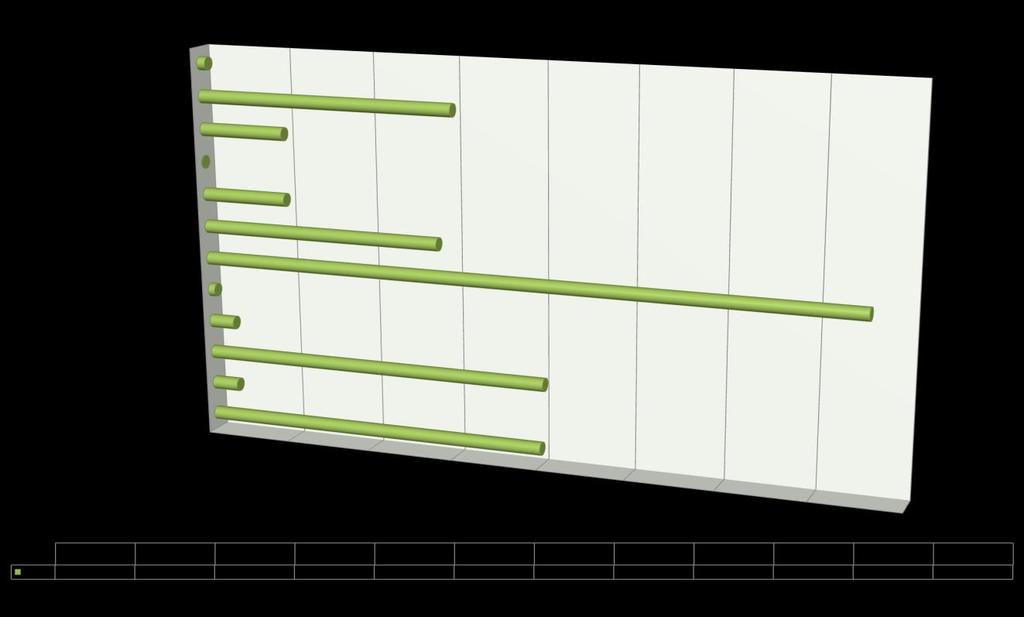
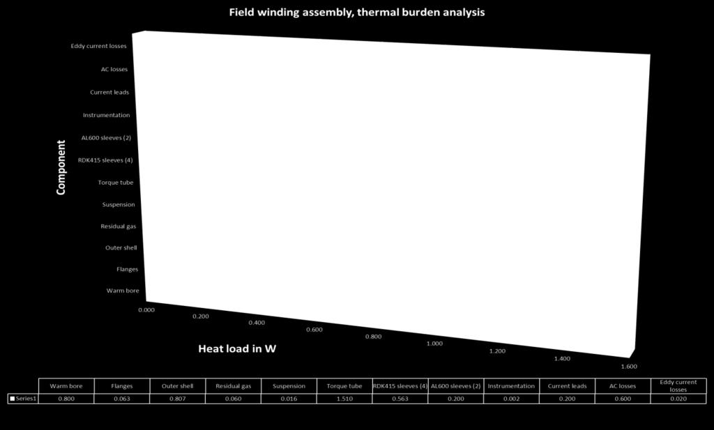
20 Heat loads 20 of 29 20


 Field Support")
 Double")

21 Generator mechanical sub-systems Armature Assembly Armature Support Field Assembly Armature Shaft & Hub Flange (to Blades) Field Support Field Shaft & Gooseneck Flange (to Tower) Double Row Tapered Roller Bearing Cylindrical Roller Bearing 21 of 29 21

 Safety Factor Nominal - 12% 37 10.3 Extreme < 50 % 41% 287 1.")

22 Supporting structure analysis Standard Gravity Wind Load (Nodding Moment) Nominal = 5.8e9 N-mm Extreme = 5.1e10 N-mm EM Load Need latest Nominal = 160 psi Deflection Load = 5.4e6 N/in Bearing design summary Loads Air Gap Closedown Spec Air Gap Actual Closedown Max Stress (MPa) Safety Factor Nominal - 12% Extreme < 50 % 41% of 29 Industry proven configuration Sized against wind extreme loads using Wind Turbine Design Tools Bearing Stiffness calculated using Bearing Design Tools 25+ years life estimation 22

 Max Rotational displacement (mm) Thermal barrier concept OVC 6061-T6 40-300 288 30 9.6 0.03 0.04 TS 1100 40-60 63 10 6.3 1.22 15.")
23 Field assembly torque tube design The torque tube has to meet several key design constraints: extreme torque load conditions with respect to buckling exceptional fatigue properties, and in particular at low temperatures light weight, ease of manufacture minimal heat burden to magnet coil former with respect to thermal conductivity minimal thermal radiation minimum of optically black cavities or so-called black holes simple and uncompromised application of MLI should be possible Material Working temperatu re (K) Tensile Strength, Yield (Mpa)* Max Stress (MPa) Max Stress SF Max Radial displacement (mm) Max Rotational displacement (mm) Thermal barrier concept OVC 6061-T TS Upper TT Lower TT TiAl6V4 TiAl6V Coil former Coils A356-T61 NbTi composite of 29 23
24 LTSC generator COE Drivetrain Capex LTSC Generator allows Increasing turbine size to 10MW with reducing drivetrain cost ($/kw) by 30% over PMDD, 38% over Geared, 28% over HTSCG PMDD cost based on 2010 Maples et al. (NREL/TP ), which assumes 2010 rare-earth material prices. Actual PMDD generator costs much higher today. Cost of Energy Baseline is 5MW-126m Proposed LTSC Gen is 10MW-160m COE Reduction 24 of 29 13% reduction from PMDD, potentially higher due to increased PMDD cost in last 2 years, further potential to reduce SC wire cost 18% reduction over geared 24

25 Component risk identification 25 of 29 25

26 Technology Readiness Level Analysis Sub-System Armature Superconducting Field Cryogenic Cooling Mechanical PHASE 1 PHASE 2 projected % lower than TRL4 10 % 28 % 0% % lower than TRL4 0% 0% 0% 43% 28 % 26 of 29 26
27 Conclusions Superconductivity is competing against well-established and well-understood technology. The political pressures already exist to reduce the cost of energy and to minimize the effect on the environment. Until we can get systems out there working in the real world, we will never get sufficient data to be able to prove once and for all that this technology can be the answer to many of our energy-related problems. 27 of 29 27
28 Team acknowledgements 28 of 29 28

29 Thank you. 29 of 29 29
Next Generation Drive Train Superconductivity for Large-Scale Wind Turbines*
 Next Generation Drive Train Superconductivity for Large-Scale Wind Turbines* Applied Superconductivity Conference, Portland, Oregon October 11th, 2012 R. Fair, W. Stautner, M. Douglass, R. Rajput-Ghoshal,
M. A. Green, and S. Yu Lawrence Berkeley National Laboratory, Berkeley CA 94720, USA
 LBNL-48445 SCMAG-749 SUPERCONDUCTING MAGNETS FOR INDUCTION LINAC PHASE-ROTATION IN A NEUTRINO FACTORY M. A. Green, and S. Yu Lawrence Berkeley National Laboratory, Berkeley CA 94720, USA ABSTRACT The neutrino
HTS Machines for Applications in All-Electric Aircraft
 University Research Engineering Technology Institute on Aeropropulsion & Power Technology Power Engineering Society General Meeting 2007 HTS Machines for Applications in All-Electric Aircraft Philippe
Review and update on MAGLEV
 EUROPEAN CRYOGENICS DAYS 2017 (Karlsruhe, Germany, September 13, 2017) Review and update on MAGLEV Hiroyuki Ohsaki The University of Tokyo, Japan Outline Review and update on MAGLEV 1. Introduction 2.
Superconducting Generators for Large Wind Turbine: Design Trade-Off and Challenges
 Superconducting Generators for Large Wind Turbine: Design Trade-Off and Challenges Philippe J. Masson, Vernon Prince Advanced Magnet Lab Palm Bay, FL CEC ICMC 2011 CEC-ICMC 2011, S Spokane, k WA June 16th,
CHAPTER 3 DESIGN OF THE LIMITED ANGLE BRUSHLESS TORQUE MOTOR
 33 CHAPTER 3 DESIGN OF THE LIMITED ANGLE BRUSHLESS TORQUE MOTOR 3.1 INTRODUCTION This chapter presents the design of frameless Limited Angle Brushless Torque motor. The armature is wound with toroidal
Solenoid Magnets for the Front End of a Neutrino Factory
 Solenoid Magnets for the Front End of a Neutrino Factory M.A. Green and S.S. Yu Lawrence Berkeley National Laboratory, Berkeley CA 94720 J.R. Miller and S. Prestemon National High Magnetic Field Laboratory,
Stray Losses in Power Transformers
 Stray Losses in Power Transformers Stray Losses in Power Transformers Pradeep Ramaswamy Design & Development Engineer Pradeep.Ramaswamy@spx.com 2 Agenda 1. Definition 2. Formation & Characteristics 3.
CHAPTER 6 DESIGN AND DEVELOPMENT OF DOUBLE WINDING INDUCTION GENERATOR
 100 CHAPTER 6 DESIGN AND DEVELOPMENT OF DOUBLE WINDING INDUCTION GENERATOR 6.1 INTRODUCTION Conventional energy resources are not sufficient to meet the increasing electrical power demand. The usages of
International Journal of Computer Engineering and Applications, Volume XII, Special Issue, March 18, ISSN
 DESIGN AND CONSTRUCTION OF LINEAR MOTOR FOR LINEAR COMPRESSOR USED IN HOUSEHOLD REFRIGERATOR Dr. Priya Nitin Gokhale, IEEE Member Professor, Dept of Electrical Engineering Jayawantrao Sawant College of
DESIGN OF DC MACHINE
 DESIGN OF DC MACHINE 1 OUTPUT EQUATION P a = power developed by armature in kw P = rating of machine in kw E = generated emf, volts; V = terminal voltage, volts p = number of poles; I a = armaure current,
CHAPTER 4 HARDWARE DEVELOPMENT OF DUAL ROTOR RADIAL FLUX PERMANENT MAGNET GENERATOR FOR STAND-ALONE WIND ENERGY SYSTEMS
 66 CHAPTER 4 HARDWARE DEVELOPMENT OF DUAL ROTOR RADIAL FLUX PERMANENT MAGNET GENERATOR FOR STAND-ALONE WIND ENERGY SYSTEMS 4.1 INTRODUCTION In this chapter, the prototype hardware development of proposed
Figure 4.1.1: Cartoon View of a DC motor
 Problem 4.1 DC Motor MASSACHUSETTS INSTITUTE OF TECHNOLOGY Department of Electrical Engineering and Computer Science 6.007 Applied Electromagnetics Spring 2011 Problem Set 4: Forces and Magnetic Fields
2014 ELECTRICAL TECHNOLOGY
 SET - 1 II B. Tech I Semester Regular Examinations, March 2014 ELECTRICAL TECHNOLOGY (Com. to ECE, EIE, BME) Time: 3 hours Max. Marks: 75 Answer any FIVE Questions All Questions carry Equal Marks ~~~~~~~~~~~~~~~~~~~~~~~~~~
Electrical Machines -II
 Objective Type Questions: 1. Basically induction machine was invented by (a) Thomas Alva Edison (b) Fleming (c) Nikola Tesla (d) Michel Faraday Electrical Machines -II 2. What will be the amplitude and
MAIN SHAFT SUPPORT FOR WIND TURBINE WITH A FIXED AND FLOATING BEARING CONFIGURATION
 Technical Paper MAIN SHAFT SUPPORT FOR WIND TURBINE WITH A FIXED AND FLOATING BEARING CONFIGURATION Tapered Double Inner Row Bearing Vs. Spherical Roller Bearing On The Fixed Position Laurentiu Ionescu,
COMPARISON OF PERFORMANCE FEATURES
 SERVODISC CATALOG A new dimension in performance If you are involved with high performance servomotor applications, there is an important motor technology which you should know about. It s the technology
Development and Performance Evaluation of High-reliability Turbine Generator
 Hitachi Review Vol. 52 (23), No. 2 89 Development and Performance Evaluation of High-reliability Turbine Generator Hiroshi Okabe Mitsuru Onoda Kenichi Hattori Takashi Watanabe, Dr. Eng. Hisashi Morooka
Extended requirements on turbogenerators
 , Siemens AG, Mülheim/Ruhr, Germany Extended requirements on turbogenerators due to changed operational regimes siemens.com Table of Content Evaluation of current operation regimes Extended requirements
Sub:EE6604/DESIGN OF ELECTRICAL MACHINES Unit V SYNCHRONOUS MACHINES. 2. What are the two type of poles used in salient pole machines?
 SRI VIDYA COLLEGE OF ENGINEERING & TECHNOLOGY DEPARTMENT OF EEEE QUESTION BANK Sub:EE6604/DESIGN OF ELECTRICAL MACHINES Unit V SYNCHRONOUS MACHINES 1. Name the two types of synchronous machines. 1. Salient
Permanent magnet machines and actuators
 Permanent magnet machines and actuators Geraint Jewell The University of Sheffield Symposium on Materials for a Sustainable Future 11/09/09 1 Key PM Properties for Electro-Mechanical Devices High remanence
1 st DeepWind 5 MW baseline design
 1 st DeepWind 5 MW baseline design 9 th Deep Sea Offshore Wind R&D Seminar 19-20/01/2012 Trondheim, Norway Uwe Schmidt Paulsen a uwpa@dtu.dk Luca Vita a Helge A. Madsen a Jesper Hattel b Ewen Ritchie c
Design Considerations for a Direct Drive Motor Retrofit on an ACC
 Design Considerations for a Direct Drive Motor Retrofit on an ACC Tom Weinandy September 23, 2014 Introduction This presentation is focused on reviewing the design concepts for retrofitting an installation
TORQUE-MOTORS. as Actuators in Intake and Exhaust System. SONCEBOZ Rue Rosselet-Challandes 5 CH-2605 Sonceboz.
 TORQUE-MOTORS as Actuators in Intake and Exhaust System SONCEBOZ Rue Rosselet-Challandes 5 CH-2605 Sonceboz Tel.: +41 / 32-488 11 11 Fax: +41 / 32-488 11 00 info@sonceboz.com www.sonceboz.com as Actuators
VALLIAMMAI ENGINEERING COLLEGE
 VALLIAMMAI ENGINEERING COLLEGE SRM Nagar, Kattankulathur 603 203. DEPARTMENT OF ELECTRICAL AND ELECTRONICS ENGINEERING Question Bank EE6401 ELECTRICAL MACHINES I UNIT I: MAGNETIC CIRCUITS AND MAGNETIC
Development of a Superconducting High-Speed Flywheel Energy Storage System
 Juni 2015 Development of a Superconducting High-Speed Flywheel Energy Storage System W. Walter 8. Braunschweiger Supraleiterseminar 2015 Outline Background SC bearing prototype Technology demonstrator
 APGENCO/APTRANSCO Assistant Engineer Electrical Previous Question Papers Q.1 The two windings of a transformer is conductively linked. inductively linked. not linked at all. electrically linked. Q.2 A
The Results of the KSTAR Superconducting Coil Test
 1 FT/3-2 The Results of the KSTAR Superconducting Coil Test Y. K. Oh, Y. Chu, S. Lee, S. J. Lee, S. Baek, J. S. Kim, K. W. Cho, H. Yonekawa, Y. Chang, K. R. Park, W. Chung, S. H. Lee, S. H. Park, I. S.
SUSPENSION 04 CLAMPS
 SUSPENSION CLAMPS 04 4 SUSPENSION CLAMPS 57 Contents General... 58 Suspension clamp trunnion type, forged,... 63 Suspension clamp trunnion type, forged, with bigger angle of deflection, for aluminium based
Synchronous Generators I. EE 340 Spring 2011
 Synchronous Generators I EE 340 Spring 2011 Construction of synchronous machines In a synchronous generator, a DC current is applied to the rotor winding producing a rotor magnetic field. The rotor is
Cutting-edge technologies backed by a century of experience
 AHNAM is the world's leading supplier of high voltage induction machines used in a wide range of application in virtually every industry including oil, gas & petrochemicals, power generation, marine, pulp
Renewable Energy Systems 13
 Renewable Energy Systems 13 Buchla, Kissell, Floyd Chapter Outline Generators 13 Buchla, Kissell, Floyd 13-1 MAGNETISM AND ELECTROMAGNETISM 13-2 DC GENERATORS 13-3 AC SYNCHRONOUS GENERATORS 13-4 AC INDUCTION
Development of Large-capacity Indirect Hydrogen-cooled Turbine Generator and Latest Technologies Applied to After Sales Service
 Development of Large-capacity Indirect Hydrogen-cooled Turbine Generator and Latest Technologies Applied to After Sales Service 39 KAZUHIKO TAKAHASHI *1 MITSURU ONODA *1 KIYOTERU TANAKA *2 SEIJIRO MURAMATSU,
Synchronous Generators I. Spring 2013
 Synchronous Generators I Spring 2013 Construction of synchronous machines In a synchronous generator, a DC current is applied to the rotor winding producing a rotor magnetic field. The rotor is then turned
SuperPower 2G HTS Wire for Demanding Electric Power Applications
 superior performance. powerful technology. SuperPower 2G HTS Wire for Demanding Electric Power Applications Traute F. Lehner Sr. Director of Marketing & Govt Affairs, SuperPower Inc. The 10 th EPRI Superconductivity
Power Losses. b. Field winding copper losses Losses due to the shunt field (i sh 2 R sh. ) or series field winding (i s 2 R s
 or series field winding (i s 2 R s") Power Losses The various losses inside a generator can be subdivided according to: 1. copper losses a. armature copper losses = i a 2 R a Where R is the resistance of the armature, interpoles and series
Power Losses The various losses inside a generator can be subdivided according to: 1. copper losses a. armature copper losses = i a 2 R a Where R is the resistance of the armature, interpoles and series
Converteam: St. Mouty, A. Mirzaïan FEMTO-ST: A. Berthon, D. Depernet, Ch. Espanet, F. Gustin
 Permanent Magnet Design Solutions for Wind Turbine applications Converteam: St. Mouty, A. Mirzaïan FEMTO-ST: A. Berthon, D. Depernet, Ch. Espanet, F. Gustin Outlines 1. Description of high power electrical
SuperPower 2G HTS Wire for Demanding Electric Power Applications
 superior performance. powerful technology. SuperPower 2G HTS Wire for Demanding Electric Power Applications Traute F. Lehner Sr. Director of Marketing & Govt Affairs, SuperPower Inc. The 10 th EPRI Superconductivity
INSTITUTE OF AERONAUTICAL ENGINEERING Dundigal, Hyderabad
 INSTITUTE OF AERONAUTICAL ENGINEERING Dundigal, Hyderabad - 500 043 MECHANICAL ENGINEERING ASSIGNMENT Name : Electrical and Electronics Engineering Code : A40203 Class : II B. Tech I Semester Branch :
Application Notes. Calculating Mechanical Power Requirements. P rot = T x W
 Application Notes Motor Calculations Calculating Mechanical Power Requirements Torque - Speed Curves Numerical Calculation Sample Calculation Thermal Calculations Motor Data Sheet Analysis Search Site
High Voltage Generators. TM21-TG Series. 2-Pole Air Cooled Turbine Generator Up to 80,000 kw (107,000 HP)
") High Voltage Generators TM21-TG Series 2-Pole Air Cooled Turbine Generator Up to 80,000 kw (107,000 HP) TMEIC has a proud and rich history of providing the latest generator technology for a broad range
High Voltage Generators TM21-TG Series 2-Pole Air Cooled Turbine Generator Up to 80,000 kw (107,000 HP) TMEIC has a proud and rich history of providing the latest generator technology for a broad range
INFN LNF DAΦNE. DAΦNE Storage Ring. Laminated Yoke Quadrupole Low carbon steel Magnetil B-C
 and Storage Ring In 1993 the Company was awarded by INFN-LNF a contract for the turn-key construction of the Transfer Lines for the e+e-φ-factory DAΦNE in Frascati - Rome. The contract included resistive
Intermediate weight at 155kg Peak continuous fields up to 3 T for 15mm pole face diameter at 8mm gap Any mounting orientation Fast cycle times
 OVERVIEW The 5405 dipole electromagnet is a fit, form and function upgrade for the 5403 electromagnet system. This upgrade provides approximately 40% more field for a given pole gap. The 5405 is shipped
Comparison of different 600 kw designs of a new permanent magnet generator for wind power applications
 Comparison of different 600 kw designs of a new permanent magnet generator for wind power applications E. Peeters, Vito, Boeretang 200, 2400 Mol, Belgium, eefje.peeters@vito.be, tel +32 14 33 59 23, fax
Possible Solutions to Overcome Drawbacks of Direct-Drive Generator for Large Wind Turbines
 Possible Solutions to Overcome Drawbacks of Direct-Drive Generator for Large Wind Turbines 1. Introduction D. Bang, H. Polinder, G. Shrestha, J.A. Ferreira Electrical Energy Conversion / DUWIND Delft University
Universal computer aided design for electrical machines
 Neonode Inc From the SelectedWorks of Dr. Rozita Teymourzadeh, CEng. 2012 Universal computer aided design for electrical machines Aravind CV Grace I Rozita Teymourzadeh Rajkumar R Raj R, et al. Available
Generators for the age of variable power generation
 6 ABB REVIEW SERVICE AND RELIABILITY SERVICE AND RELIABILITY Generators for the age of variable power generation Grid-support plants are subject to frequent starts and stops, and rapid load cycling. Improving
Galapagos San Cristobal Wind Project. VOLT/VAR Optimization Report. Prepared by the General Secretariat
 Galapagos San Cristobal Wind Project VOLT/VAR Optimization Report Prepared by the General Secretariat May 2015 Foreword The GSEP 2.4 MW Wind Park and its Hybrid control system was commissioned in October
SOLUTIONS FOR SAFE HOT COIL EVACUATION AND COIL HANDLING IN CASE OF THICK AND HIGH STRENGTH STEEL
 SOLUTIONS FOR SAFE HOT COIL EVACUATION AND COIL HANDLING IN CASE OF THICK AND HIGH STRENGTH STEEL Stefan Sieberer 1, Lukas Pichler 1a and Manfred Hackl 1 1 Primetals Technologies Austria GmbH, Turmstraße
Hydraulic Flywheel Accumulator for Mobile Energy Storage
 Hydraulic Flywheel Accumulator for Mobile Energy Storage Paul Cronk University of Minnesota October 14 th, 2015 I. Overview Outline I. Background on Mobile Energy Storage II. Hydraulic Flywheel Accumulator
LIMITED ANGLE TORQUE MOTORS
 LIMITED ANGLE TORQUE MOTORS Limited Angle Torque Motors H2W Technologies Limited Angle Torque Motors are ideal for compact, limited angular excursion (
FUNDAMENTAL SAFETY OVERVIEW VOLUME 2: DESIGN AND SAFETY CHAPTER E: THE REACTOR COOLANT SYSTEM AND RELATED SYSTEMS
 PAGE : 1 / 13 4. PRESSURISER 4.1. DESCRIPTION The pressuriser (PZR) is a pressurised vessel forming part of the reactor coolant pressure boundary (CPP) [RCPB]. It comprises a vertical cylindrical shell,
Key Stellarator Engineering Issues and Constraints
 Key Stellarator Engineering Issues and Constraints P. Heitzenroeder for the NCSX Engineering Team ARIES Meeting at PPPL - October, 2002 1 How The Engineering of a Compact Stellarator Differs from Most
Commutation Assembly and Adjustment Details Make the Difference Gary Lozowski Morgan Advanced Materials June 13, MEMSA Technical Symposium
 Commutation Assembly and Adjustment Details Make the Difference Gary Lozowski Morgan Advanced Materials June 13, 2014 @ MEMSA Technical Symposium COMMUTATION Commutation is the Reversal of Armature Current
TEMPERATURE AND STRESS IN ALCATOR C-MOD DUE TO THE DIVERTOR UPGRADE
 THERMAL ANALYSIS TO CALCULATE THE VESSEL TEMPERATURE AND STRESS IN ALCATOR C-MOD DUE TO THE DIVERTOR UPGRADE Han Zhang 1, Peter H. Titus 1, Robert Ellis 1, Soren Harrison 1,2, Rui Vieira 2 1 Princeton
PF Coil 2-6 Supply. Main technical aspects. P. Valente
 PF Coil 2-6 Supply Main technical aspects P. Valente PF Coils EI Information Meeting Cadarache, 19 February 2013 This presentation is intended for reference purposes only and is not a legally binding document
PF Coil Fabrication Overview
 PF Coil Fabrication Overview PF Coils Information Meeting Barcelona - 15 th October 2012 This presentation is intended for reference purposes only and is not a legally binding document PF Building Layout
Permanent Magnet Motors for ESP Applications Updating the Track Record of Performance. Lorne Simmons VP Sales & Marketing
 2019 Permanent Magnet Motors for ESP Applications Updating the Track Record of Performance Lorne Simmons VP Sales & Marketing Technology Development Milestones and Achievements Late 1990s Permanent Magnet
Efficiency Increment on 0.35 mm and 0.50 mm Thicknesses of Non-oriented Steel Sheets for 0.5 Hp Induction Motor
 International Journal of Materials Engineering 2012, 2(2): 1-5 DOI: 10.5923/j.ijme.20120202.01 Efficiency Increment on 0.35 mm and 0.50 mm Thicknesses of Non-oriented Steel Sheets for 0.5 Hp Induction
DHANALAKSHMI SRINIVASAN COLLEGE OF ENGINEERING AND TECHNOLOGY MAMALLAPURAM, CHENNAI
 DHANALAKSHMI SRINIVASAN COLLEGE OF ENGINEERING AND TECHNOLOGY MAMALLAPURAM, CHENNAI -603104 DEPARTMENT OF ELECTRICAL AND ELECTRONICS ENGINEERING QUESTION BANK VII SEMESTER EE6501-Power system Analysis
SIMULINK Based Model for Determination of Different Design Parameters of a Three Phase Delta Connected Squirrel Cage Induction Motor
 IOSR Journal of Electrical and Electronics Engineering (IOSR-JEEE) e-issn: 2278-1676,p-ISSN: 2320-3331, Volume 7, Issue 4 (Sep. - Oct. 2013), PP 25-32 SIMULINK Based Model for Determination of Different
EXAMPLES GEARS. page 1
 (EXAMPLES GEARS) EXAMPLES GEARS Example 1: Shilds p. 76 A 20 full depth spur pinion is to trans mit 1.25 kw at 850 rpm. The pinion has 18 teeth. Determine the Lewis bending stress if the module is 2 and
FARADAY S LAW ELECTROMAGNETIC INDUCTION
 FARADAY S LAW ELECTROMAGNETIC INDUCTION magnetic flux density, magnetic field strength, -field, magnetic induction [tesla T] magnetic flux [weber Wb or T.m 2 ] A area [m 2 ] battery back t T f angle between
ANSWER KEY. Using Electricity and Magnetism. Chapter Project Worksheet 1
 Using Electricity and Magnetism Using Electricity and Magnetism Chapter Project Worksheet 1 1 6. Students data will vary greatly depending on the appliances and devices they examine as well as on the size
9-O-3A-4 Cryogenic system for the 43 T Hybrid Magnet at LNCMI Grenoble From the needs to the commissioning
 9-O-3A-4 Cryogenic system for the 43 T Hybrid Magnet at LNCMI Grenoble From the needs to the commissioning L. Ronayette, G. Caplanne, P. Hanoux, R. Pfister, M. Pissard, P. Pugnat CNRS-LNCMI, Grenoble,
SIDDHARTH GROUP OF INSTITUTIONS :: PUTTUR
 SIDDHARTH GROUP OF INSTITUTIONS :: PUTTUR Siddharth Nagar, Narayanavanam Road 517583 QUESTION BANK (DESCRIPTIVE) Subject with Code : ET(16EE212) Year & Sem: II-B.Tech & II-Sem UNIT I DC GENERATORS Course
of coper bars of equal size, each insulated from the
 manufacture is kept secret in order to keep their rivals from gaining any detrimental information; thus the public does not obtainany of the details of the construction of these world wide utilities. 'lectrical
Update. This week A. B. Kaye, Ph.D. Associate Professor of Physics. Michael Faraday
 10/26/17 Update Last week Completed Sources of Magnetic Fields (Chapter 30) This week A. B. Kaye, Ph.D. Associate Professor of Physics (Chapter 31) Next week 30 October 3 November 2017 Chapter 32 Induction
ECE 325 Electric Energy System Components 6 Three Phase Induction Motors. Instructor: Kai Sun Fall 2016
 ECE 325 Electric Energy System Components 6 Three Phase Induction Motors Instructor: Kai Sun Fall 2016 1 Content (Materials are from Chapters 13-15) Components and basic principles Selection and application
Electrical Theory. Generator Theory. PJM State & Member Training Dept. PJM /22/2018
 Electrical Theory Generator Theory PJM State & Member Training Dept. PJM 2018 Objectives The student will be able to: Describe the process of electromagnetic induction Identify the major components of
CHAPTER 1 INTRODUCTION
 1 CHAPTER 1 INTRODUCTION 1.1 ELECTRICAL MOTOR This thesis address the performance analysis of brushless dc (BLDC) motor having new winding method in the stator for reliability requirement of electromechanical
OPTIMIZATION IN GENERATION FROM A HORIZONTAL AXIS WIND TURBINE VIA BLADE PITCH CONTROL AND STRUCTURE MORPHING
 OPTIMIZATION IN GENERATION FROM A HORIZONTAL AXIS WIND TURBINE VIA BLADE PITCH CONTROL AND STRUCTURE MORPHING PROJECT REFERENCE NO. : 37S1312 COLLEGE : SIDDAGANGA INSTITUTE OF TECHNOLOGY, TUMKUR BRANCH
Electric Drive - Magnetic Suspension Rotorcraft Technologies
 Electric Drive - Suspension Rotorcraft Technologies William Nunnally Chief Scientist SunLase, Inc. Sapulpa, OK 74066-6032 wcn.sunlase@gmail.com ABSTRACT The recent advances in electromagnetic technologies
Chapter 3.2: Electric Motors
 Part I: Objective type questions and answers Chapter 3.2: Electric Motors 1. The synchronous speed of a motor with 6 poles and operating at 50 Hz frequency is. a) 1500 b) 1000 c) 3000 d) 750 2. The efficiency
SSC-JE STAFF SELECTION COMMISSION ELECTRICAL ENGINEERING STUDY MATERIAL ELECTRICAL MACHINES
 1 SSC-JE STAFF SELECTION COMMISSION ELECTRICAL ENGINEERING STUDY MATERIAL 28-B/7, Jia Sarai, Near IIT, Hauz Khas, New Delhi-110016. Ph. 011-26514888. www.engineersinstitute.com 2 CONTENT 1. : DC MACHINE,
EFFECT OFSHIMMING ON THE ROTORDYNAMIC FORCE COEFFICIENTS OF A BUMP TYPE FOIL BEARING TRC-B&C
 TRC Project 32513/1519F3 EFFECT OFSHIMMING ON THE ROTORDYNAMIC FORCE COEFFICIENTS OF A BUMP TYPE FOIL BEARING TRC-B&C-01-2014 A Shimmed Bump Foil Bearing: Measurements of Drag Torque, Lift Off Speed, and
UNIT I D.C. MACHINES PART A. 3. What are factors on which hysteresis loss? It depends on magnetic flux density, frequency & volume of the material.
 EE6352-ELECTRICAL ENGINEERING AND INSTRUMENTATION UNIT I D.C. MACHINES PART A 1. What is prime mover? The basic source of mechanical power which drives the armature of the generator is called prime mover.
Excitation system is of Static Silicon Excitation System, including excitation transformer, thyristors, and AVR.
 Turbo - Generator Type: QF Series 1. General The generator is a two pole, cylindrical rotor type synchronous machine, directly coupled with steam turbine. It has a closed-circuit cooling system to cool
Thermal Analysis of Electric Machines Motor-CAD
 Thermal Analysis of Electric Machines Motor-CAD Create, Design, Engineer! Brief Look at MotorCAD geometry input using dedicated editors select materials, cooling options All difficult heat transfer data
EE5940: Wind Essen.als. Materials and Structural Reliability Sue Mantell Mechanical Engineering
 EE5940: Wind Essen.als Materials and Structural Reliability Sue Mantell Mechanical Engineering Focus on Rotor Blades Overview the most complex structural component of a wind turbine Quick overview of Loads
NODIA AND COMPANY. Model Test Paper - I GATE Machine Design. Copyright By Publishers
 No part of this publication may be reproduced or distributed in any form or any means, electronic, mechanical, photocopying, or otherwise without the prior permission of the author. Model Test Paper -
CHAPTER 5 ANALYSIS OF COGGING TORQUE
 95 CHAPTER 5 ANALYSIS OF COGGING TORQUE 5.1 INTRODUCTION In modern era of technology, permanent magnet AC and DC motors are widely used in many industrial applications. For such motors, it has been a challenge
Available online at ScienceDirect. Procedia CIRP 33 (2015 )
") Available online at www.sciencedirect.com ScienceDirect Procedia CIRP 33 (2015 ) 581 586 9th CIRP Conference on Intelligent Computation in Manufacturing Engineering - CIRP ICME '14 Magnetic fluid seal
Available online at www.sciencedirect.com ScienceDirect Procedia CIRP 33 (2015 ) 581 586 9th CIRP Conference on Intelligent Computation in Manufacturing Engineering - CIRP ICME '14 Magnetic fluid seal
Modeling and Optimization of a Linear Electromagnetic Piston Pump
 Fluid Power Innovation & Research Conference Minneapolis, MN October 10 12, 2016 ing and Optimization of a Linear Electromagnetic Piston Pump Paul Hogan, MS Student Mechanical Engineering, University of
Single-phase Coolant Flow and Heat Transfer
 22.06 ENGINEERING OF NUCLEAR SYSTEMS - Fall 2010 Problem Set 5 Single-phase Coolant Flow and Heat Transfer 1) Hydraulic Analysis of the Emergency Core Spray System in a BWR The emergency spray system of
CRYOGENIC MOTORS FOR HERSCHEL/PACS AND JAMES WEBB/MIRI AND NIRSPEC
 CRYOGENIC MOTORS FOR HERSCHEL/PACS AND JAMES WEBB/MIRI AND NIRSPEC I. Arend (), M. Schoele (), U. Ruppert (), Z. Szücs () () FUB (Free University of Berlin), Department of Physics, Low Temperature Laboratory,
Characteristics Analysis of Novel Outer Rotor Fan-type PMSM for Increasing Power Density
 Journal of Magnetics 23(2), 247-252 (2018) ISSN (Print) 1226-1750 ISSN (Online) 2233-6656 https://doi.org/10.4283/jmag.2018.23.2.247 Characteristics Analysis of Novel Outer Rotor Fan-type PMSM for Increasing
Chapter 6 Generator-Voltage System
 Chapter 6 Generator-Voltage System 6-1. General The generator-voltage system described in this chapter includes the leads and associated equipment between the generator terminals and the low-voltage terminals
Driving Characteristics of Cylindrical Linear Synchronous Motor. Motor. 1. Introduction. 2. Configuration of Cylindrical Linear Synchronous 1 / 5
 1 / 5 SANYO DENKI TECHNICAL REPORT No.8 November-1999 General Theses Driving Characteristics of Cylindrical Linear Synchronous Motor Kazuhiro Makiuchi Satoshi Sugita Kenichi Fujisawa Yoshitomo Murayama
High Performance Machine Design Considerations
 High Performance Machine Design Considerations High Performance Machine Design Considerations Abstract From Formula One race cars to consumer vehicles, the demand for high performing, energy efficient
2 Pole 1222MVA Turbo-Generator & 4 Pole 1690MVA Turbo-Generator
 2 Pole 1222MVA Turbo-Generator & 4 Pole 1690MVA Turbo-Generator 27. August, 2008 Generator Design Team Chong Whie Cho 2008 CIGRE SESSION 42, Paris CONTENTS Introduction 2-Pole 1222MVA Generator - Specifications
OPTIMIZATION STUDIES OF ENGINE FRICTION EUROPEAN GT CONFERENCE FRANKFURT/MAIN, OCTOBER 8TH, 2018
 OPTIMIZATION STUDIES OF ENGINE FRICTION EUROPEAN GT CONFERENCE FRANKFURT/MAIN, OCTOBER 8TH, 2018 M.Sc. Oleg Krecker, PhD candidate, BMW B.Eng. Christoph Hiltner, Master s student, Affiliation BMW AGENDA
ITER G A0 FDR R1.0
 2.1 Magnets 2.1.1 Magnet System General Description 1 2.1.1.1 System Description and Main Parameters 1 2.1.1.2 Physical and Functional Interfaces 4 2.1.1.3 Heat Loads 6 2.1.2 Magnet Structures 7 2.1.2.1
Design and manufacturing status of Trim Coils for the Wendelstein 7-X stellarator experiment
 Design and manufacturing status of Trim Coils for the Wendelstein 7-X stellarator experiment K. Riße a, Th. Rummel a, S. Freundt a, A. Dudek a, S. Renard a, V. Bykov a, M. Köppen a ; S. Langish b, G.H.
Intermediate weight at 155kg Peak continuous fields up to 3 T for 15mm pole face diameter at 8mm gap Any mounting orientation Fast cycle times
 OVERVIEW The 5405 dipole electromagnet is a fit, form and function upgrade for the 5403 electromagnet system. This upgrade provides approximately 40% more field for a given pole gap. The 5405 is shipped
POWER QUALITY IMPROVEMENT BASED UPQC FOR WIND POWER GENERATION
 International Journal of Latest Research in Science and Technology Volume 3, Issue 1: Page No.68-74,January-February 2014 http://www.mnkjournals.com/ijlrst.htm ISSN (Online):2278-5299 POWER QUALITY IMPROVEMENT
James Goss, Mircea Popescu, Dave Staton. 11 October 2012, Stuttgart, Germany
 Implications of real-world drive cycles on efficiencies and life cycle costs of two solutions for HEV traction: Synchronous PM motor vs Copper Rotor - IM James Goss, Mircea Popescu, Dave Staton 11 October
CSDA Best Practice. Hi-Cycle Concrete Cutting Equipment. Effective Date: Oct 1, 2010 Revised Date:
 CSDA Best Practice Title: Hi-Cycle Concrete Cutting Equipment Issue No: CSDA-BP-010 : Oct 1, 2010 Revised : Introduction Hi-cycle/high frequency concrete cutting equipment has become more prevalent in
BELT-DRIVEN ALTERNATORS
 CHAPTER 13 BELT-DRIVEN ALTERNATORS INTRODUCTION A generator is a machine that converts mechanical energy into electrical energy using the principle of magnetic induction. This principle is based on the
Advantages of a Magnetically Driven Gear Pump By Steven E. Owen, P.E.
 Advantages of a Magnetically Driven Gear Pump By Steven E. Owen, P.E. Introduction Before considering a magnetically driven pump for use in a fluid system, it is best to know something about the technology