WPS-104 Heater. Installation Instructions
|
|
|
- Ira West
- 6 years ago
- Views:
Transcription

1 WPS-104 Heater Installation Instructions

2 For 2007 vehicles see page 15 WPS 104 HEATER SYSTEM INSTALLATION INSTRUCTIONS If this is a complete installation of top, windshield and heater system, for ease of installation, it is recommended that the heater be installed first. 1. Remove the left and right side kick panels. This will require drilling out 2 rivets on each side panel. (Series 11only.) Note: To save several steps on the future installation of our WPS door system complete the following. Remove the 2, per side, 3/8 X 3/4 inch bolts going from behind the kick panel into the front wheel well, replace them with the 3/8 X 1 1/4 inch SS Button Head Cap Screws, provided in the kit. This is where the bottom of our door hinge bracket will attach to the fame. See page 12 for tips for 04 & 05 Vehicle Drill out 2 7/8 inch hole in plastic between air breathers Use the protector springs where these hoses go through new hole Run ¾ hose from bottom of heater core through this hole. Unhook the top radiator hose. Use the ¾ inch nipple to tie this hose to the one coming from the bottom of the heater core. Run the other ¾ hose direct from the top of heater core to the top radiator connection. At the same time drill an extra hole in one breather that will now have to be turned sideways to accommodate the heater blower assembly. See additional installation guide. This way you will not have to remove center floor board. Make sure there are no kinks in the hoses. 2. Raise the hood and remove both air filter inlets. 3. Behind the air inlets, locate the square steel channel cross frame. Most items behind the dash are mounted to this frame. Locate the two brackets that the shifting lever and the differential locking lever are attached to. (On the 6X6, there is only the shifting lever.) The brackets are just to the passenger s side (right) of the steering rod mounting bracket. The space between the shifter bracket and locking bracket is approximately 3inches; this is where the windshield defroster unit will be mounted. REF. PHOTO # 1 PHOTO 1 SERIES 11 MACHINES: Location of the opening for the defroster. REF. PHOTO # 2 TO AID LOCATION 2

3 Place masking tape over the dash area to the right of the driver s side hood hinge. Using the right side of the driver s hood hinge, measure over to the right 7 13/16 inches and place a mark on the masking tape. This will become the center line for the defroster cover. The defroster cover is 7" long; mark a center point at 3 ½ inches. If the windshield is not installed, use the front edge of the dash as a straight reference line. Take a square and mark a center line on the masking tape at the 7 13/16 inch mark. If the windshield is installed, use the back side of the windshield frame as a straight reference line. Take a square and mark a center line on the masking tape at the 7 13/16 inch mark. Place the defroster grate cover on the ledge, centering it on the 7 13/16 line. Align the cover with the front edge of the ledge; it needs to be close to the edge without overhanging. The end of the cover closest to the steering column should be just at the beginning of the radius going up from the ledge. Using the two holes in the cover, mark them on the masking tape. Remove the cover; there should be 3 3/16 inch between the center line and each of the two cover holes just marked. Draw a line connecting the centers of the two holes marked from the cover. Measure in from the center of each hole 11/16 inch and place a mark on the center line. Note: To insure the proper location for the defroster opening, complete the following: At the intersection of the two center lines, drill a 1/8 inch hole through the dash. Using a long drill bit or a straight rod or wire, insert it through the hole, making sure it is hanging straight down. Under the hood, make sure the rod is centered between the shifter bracket and the differential lock bracket. Refer to item #3 as this is a critical location. If it is not centered between the brackets, adjust as necessary. You do have about 1/4 inch on either side to work with. What we are looking for here is a major misalignment. If it is good, go to the next step. REF. PHOTO # 1, SPACE IS LIMITED. Using a 7/8 inch hole saw or spade bit, drill through the dash panel, centered on the mark just made. After both holes are drilled, remove the material between the holes, maintaining the 7/8 inch width. SERIES 10 MACHINES: Location of the opening for the defroster. REF. PHOTO # 2 TO AID LOCATION. Series 10 machines do not have the step down shelf on the dash Place masking tape over the dash area to the right of the driver s side hood hinge. Using the right side of the driver s hood hinge, measure over to the right, 7 5/8 inches and place a mark on the masking tape. This will become the center line for the defroster cover. The defroster cover is 7 inches long; mark a centering point, on the edges, at 3 ½ inches. If the windshield is not installed, use the front edge of the dash as a straight reference line. Take a square and mark a center line on the masking tape at the 7 5/8 inch mark. 3

4 Photo 2 If the windshield is installed, use the back side of the windshield frame as a straight reference line. Take a square and mark a center line on the masking tape at the 7 5/8 inch mark. Place the defroster grate cover on the ledge, centering it on the 7 5/8 inch line. Align the cover parallel with the front edge radius of the dash; it needs to be close to the edge without overhanging. Using the two holes in the cover, mark them on the masking tape. Remove the cover; there should be 3 3/16 inch between the center line and each of the two cover holes just marked. Draw a line connecting the centers of the two holes marked from the cover. Measure in from the center of each hole 11/16 inch and place a mark on the center line. Note: To insure the proper location for the defroster opening complete the following: At the intersection of the two center lines, drill a 1/8 inch hole through the dash. Using a long drill bit or a straight rod or wire, insert it through the hole, making sure it is hanging straight down. Under the hood, make sure the rod is centered between the shifter bracket and the differential lock bracket. Refer to item #3 as this is a critical location. If it is not centered between the brackets, adjust as necessary. You do have about 1/4 inch on either side to work with. What we are looking for here is a major misalignment. If it is good, go to the next step. REF. PHOTO # 1 SPACE IS LIMITED Using a 7/8" hole saw or spade bit, drill through the dash panel, centered on the mark just made. After both holes are drilled, remove the material between the holes, maintaining the 7/8 inch width. 4. After the slot has been cut out, attach the short piece of 2" air duct to the defroster and secure with a cable tie, then mount the defroster and the grate cover to the dash panel. 5. Locate the position for the kick panel outlets using the template provided. Use a 2-1/16 inch hole saw to make the openings. The outlet you are installing has a 2 inch dia. OD. Push the outlets though the panel; it will lock in place. Install screws in flange to keep the outlet from rotating. REF. PHOTO # 3 Photo 3 6. Cut the longer piece of 2" air duct into 2 equal lengths. Attach the air duct to the two side panel outlets and secure with cable ties. The heater core attaches to the square steel channel cross frame just to the right of the parking break mechanism. REF. PHOTO # 4 4

5 Photo 4 Route the driver s side air duct behind the dash panel, under the small storage box. Secure with a cable tie to the lower square tube cross frame. Route the passenger s side air duct up and over the top of the glove box. Remove the cup holder and push the air duct behind, up against the dash panel. Snap the cup holder back in place; this will secure the air duct in place. Note: Series 10 machines will route the passenger s side air duct along the upper cross frame and secure with cable ties Attach the short air duct to the defroster and secure with a cable tie; route it over the parking brake attachment bracket. 7. Remove the center floor pan. 8. Cut the heater hose provided in the kit into 2 sections, one being 4 ½ feet and the other 5 ½ feet. Under the hood, between the brake master cylinder and the left side air intake, you will see where the steering control rod, shifter linage, and a wire bundle pass between the outer floor panel and inner floor board panel. This is where the 2 heater hoses will pass. Push both hoses through into the center floor board cavity, about even with the two factory splices. 9. On the heater core, attach the two flat mounting plates. Make sure the flanges are facing away from the heater box. Rest the core on the lower cross frame and attach the three air ducts to the heater box. Put the defroster on the center outlet. Secure using cable ties provided in kit. It is easier at this point than doing it after the heater box has been attached. 10. With the two steel straps, carriage bolts and Nyloc nuts, attach the heater box to the upper square tube cross frame, with the air outlets facing the dash panel. Bring the carriage bolts up through the slots in the flanges, then through the straps. Do not tighten. 11. Position the heater box along the upper cross frame. It does not set square with the cross frame. The passenger s side will have about 1" of the box exposed forward of the tube; the driver s side, about 1-3/4 inches. REF. PHOTO # 5 5


6 PHOTO 5 THE MAIN CONCERN IS TO ASSURE NOTHING IS RUBBING OR INTERFERING WITH ANY CONTROLS OR CABLES. NOTE: On 05 models place the side mounting bracket with ears facing in toward center of Heater. 12. Remove the heater hose hold down clamp in the center floor area. Using vice grips or any suitable clamping device, close off only theheater hose, closest to the driver s side (left), on both sides of the splice connector. REF. PHOTO # 6 Photo 6 Take apart the clamped heater hose connection. Connect the hose coming from the engine to the shorter of the two hoses you installed from the heater core; tighten clamps. REF. PHOTO # 6 On the longer hose coming from the heater core, install one piece of the wire spring guard. The wire spring guard is used to support the hose when you make the 180 deg bend. Using the 3/4 inch splice connector, from the kit, install one end into the open factory heater hose coming from the radiator and the other end into the shorter hose coming from the heater core. Position the wire spring guard on the hose so it covers the radius of the bend. Tighten clamps. Position the 180 deg. Loop under the drive shaft and secure it with cable ties to keep it in place. REF. PHOTO # Remove the clamps from the heater hose. Position all of the hoses so they are not rubbing, making sure nothing is up against the front drive shaft. Replace the factory heater hose clamp. Using plastic cable ties, secure all of the hoses to the structure around the left side air intake tube. REF. PHOTO # 6 6
7 14. The two remaining wire spring guard will be placed over the heater hoses where it makes a sharp bend back to the core. 15. At the heater core, the SHORTER heater hose loops around the parking brake cable housing and behind where the driver s side air box will sit; it attaches to the BOTTOM FITTING on the core. Trim length to fit. Place the wire spring guard over the heater hose and attach to the bottom fitting, making sure you do not collapse the hose by making too sharp of a bend. Tighten the hose clamp. REF. PHOTO # Loop the LONGER hose between the throttle cable and brake master cylinder, following the same path as the lower hose. Trim length to fit. Place the wire spring guard, over the heater hose and connect to the UPPER FITTING, making sure you do not collapse the hose by making too sharp of a bend. Do not tighten clamp as this will be where you bleed air out of the coolant system. REF. PHOTO # 5 ELECTRICAL: 17. If you have installed the WPS106, FRONT ACCESSORY FUSE PANEL, your power supply and ground will be made from this panel. Install the rocker switch in one of the unused slots on the dash panel. Cut the wires to length and install spade connectors. Place the wires in the spiral protection shield. Follow the diagram as to the proper location of each Wire to the back of the switch.. Note: The Red wire coming from the heater blower motor is not used in this installation. It can be capped. 18. If the WPS106 is not installed, complete the following: It is recommended that an in-line fuse holder, with at least a 10 amp fuse, be used for this installation From the Hour Meter, unplug the Pink wire (Power), plug a piggy back connector into the Hour Meter with the Pink wire, then a jumper wire to the +12 connection on the back of the rocker switch. This will be your 12 volt power while the engine is running. If the engine is not running, there will not be power to the blower motor. The Black wire (Ground) from the blower motor will connect to the extra spade connection on the cigarette lighter Ground Line. If there is no extra connector, use any suitable ground connection. Note: Series 10 machines will have to use a suitable ground connection. Coolant system bleeding: Top off the radiator and make sure there is coolant in the overflow reservoir. Run the engine until the thermostat opens. Loosen the Top hose on the heater core; this will be your air bleed. You will lose some fluid but you will be able to remove the air from the system. 7

8 Check the coolant level in the reservoir often and add if needed. The efficiency of the heater and cooling system depends on all the air being out of the system. It is recommended that the coolant level be checked often during the first few hours of operation. If need be, bleed the system again After that, everything will be ready to go. REF. PHOTO # 7 PRICES AND SPECIFICATIONS ARE SUBJECT TO CHANGE WITH OUT PRIOR NOTICE. Photo 7 Updates For Installation Of WPS Vehicle 8

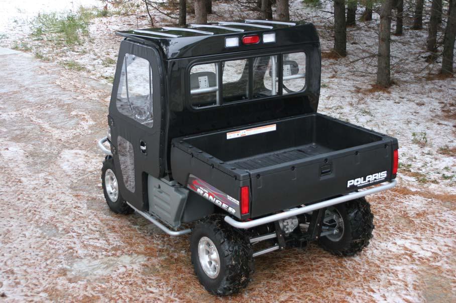
 this will give you an area to run the heater hoses.")

9 WPS-104 in 05 Vehicles When installing in the 05 Vehicle the heater mounting brackets must be installed as shown in the picture below. Remove the storage basket that is located under the hood. Remove the air intakes to give yourself some elbow room. Located between the air intakes if you reach up from the under side you will feel an opening in the steel of the plastic covered area. Cut out this area between the air intakes (2 7/8 hole saw works good) this will give you an area to run the heater hoses. Remove the upper radiator hose and use a coupler to bring the hose up to the lower core connection on the heater. Route a hose from the upper core on the heater down to the radiator. Be sure to use the hose protectors where you go through the hole between the air intakes. When you put the air breathers back in place, you will have to turn the passenger side breather sideways due to space the heater takes up. When you put the storage basket back in place you will block the air coming into the breather. Therefore it is advisable to drill a new hole in the end of the breather as shown in picture below. 9


10 The metal brackets included in this heater kit are for Relocating the relays in the 2007 models. Proud Sponsor Of PRC Forum 10
WPS-104 Heater Installation Instructions For 500EFI, 700 XP, & Crew Applications
 WPS-104 Heater Installation Instructions For 500EFI, 700 XP, & Crew Applications ORDER OF INSTALLATION FOR A COMPLETE ENCLOSURE OF A RANGERWARE WPS (Weather Protection System) IS AS FOLLOWS: 1. Heater
Rzr Heater System Part #
 Rzr Heater System Part # 2878135 NOTE: This heater unit installs below the center of the dash. If you have a radio mount kit (Polaris Part # 2876897) you may need to cut the top front corner off the mount
WOC-364 Installation Instructions Ranger XP Heater System
 WOC-364 Installation Instructions Ranger 2011-12 XP Heater System Order of installation for a Complete Enclosure Always install the Heater System first if possible NOTE: If installing the Heater System
RH INSTALL INSTRUCTIONS 2008 MODEL
 RH-800-2 INSTALL INSTRUCTIONS 2008 MODEL 1 Tips for Installing Rhinogear Products The recommended sequence for installing our Rhinogear line of products on your Rhino. This sequence will help with ease
RH INSTALL INSTRUCTIONS
 Tips for Installing Rhinogear Products The recommended sequence for installing our Rhinogear line of products on your Rhino. This sequence will help with ease of installation and help save time by eliminating
PERFECT FIT SERIES IN-DASH HEAT/ COOL/ DEFROST MUSTANG
 specializing in AIR CONDITIONING, PARTS AND SYSTEMS for your classic vehicle PERFECT FIT SERIES IN-DASH HEAT/ COOL/ DEFROST 1969-70 MUSTANG CONTROL & OPERATING INSTRUCTIONS The controls on your new Perfect
Jeep Wrangler 4.0 Liter TJ Jeep Wrangler 2.5 Liter TJ Installation instructions
 TM www.jeepair.com 1999 Jeep Wrangler 4.0 Liter TJ 1999-2001 Jeep Wrangler 2.5 Liter TJ Installation instructions Kit Information After 1994 every vehicle was designed for R134a refrigerant. The Jeep kit
Installation instructions, accessories - Fuel driven heater 912-D
 XC90 Section Group Weight(Kg/Pounds) Year Month 8 87 2002 10 XC90 2003 D5244T, XC90 2004 D5244T, XC90 2005 D5244T AW50/51 AWD, XC90 2006 D5244T, XC90 2006 D5244T AW50/51 AWD D5244T R8703687 Page 1 of 20
INSTALLATION INSTRUCTIONS
 HIGH FLOW AIRFLOW METER INSTALLATION INSTRUCTIONS PART NUMBER D763-1600A APPLICATION: 2001-06 E46 M3 Parts List: Hose clamp 64Z (7) Plastic Rivets Air Filter Temp Sensor & Harness (2) Button Head Screws
97-02 JEEP TJ BODY LIFT KIT INSTRUCTIONS
 92RC60500 97-02 JEEP TJ BODY LIFT KIT INSTRUCTIONS Congratulations on your purchase of a new Rough Country 2 /3 Body Lift. We are committed to providing you with the best product available for the best
Installation Instructions for TJ Jeep s Fiberglass Replacement Bodies and Parts
 Installation Instructions for 1997-2006 TJ Jeep s Fiberglass Replacement Bodies and Parts Getting started: We recommend that you take pictures as you dismantle your Jeep. These pictures will help you when
2013 Mustang Workshop Manual
 32. Attach the wiring harness retainers to the LH side of the oil pan and the front oil pan stud bolts and install the 2 nuts. Tighten to 8 Nm (71 lb-in). 33. Position the underbody shield and install
4. Remove (4) 10mm and (1) 7mm bolt that holds fascia at front corners, on each side
 10mm and (1) 7mm bolt that holds fascia at front corners, on each side") 2010 Camaro LS3 1. Disconnect battery ground 2. Remove front wheels 3. Remove (5) push pins and (5) #20 torx screws on inner front wheel well liners and remove liners on each side 4. Remove (4) 10mm and
2010 Camaro LS3 1. Disconnect battery ground 2. Remove front wheels 3. Remove (5) push pins and (5) #20 torx screws on inner front wheel well liners and remove liners on each side 4. Remove (4) 10mm and
Jeep Wrangler TJ. Complete Air Conditioning System. Slide Control Head. Installation instructions
 WWW.JEEPAIR.COM 1996-1998 Jeep Wrangler TJ Complete Air Conditioning System Slide Control Head Installation instructions Kit Information After 1994 every vehicle was designed for R134a refrigerant. The
Instant Chat off the main page of Or simply call our tech team at
 FRONT MOUNT INTERCOOLER 2015+ WRX 2017-07-07 Thank you for purchasing this PERRIN product for your car! Installation of this product should only be performed by persons experienced with installation of
INSTALLATION INSTRUCTIONS 97 FORD EXPEDITION
 INSTALLATION INSTRUCTIONS 97 FORD EXPEDITION 1. Read the instructions completely and carefully before you begin. Check the kit for proper contents (refer to the part s list and the picture diagrams). Before
Thank you for purchasing the Craven Speed FlexPod Complete Gauge Pod Kit
 Thank you for purchasing the Craven Speed FlexPod Complete Gauge Pod Kit Before You Start Please read instructions completely before installing. These instructions contain the information required to install
INSTALLATION INSTRUCTIONS
 2807 INSTALLATION INSTRUCTIONS SECTION - AIR SPRING SECTION 2 - AIR ACCESSORY -6 ! IMPORTANT PLEASE DON T HURT YOURSELF, YOUR KIT OR YOUR VEHICLE. TAKE A MINUTE TO READ THIS IMPORTANT INFORMATION. This
1963 GEN IV SUREFIT VINTAGE AIR CONDITIONING INSTALLATION
 by Randy Irwin 1963 GEN IV SUREFIT VINTAGE AIR CONDITIONING INSTALLATION Randy Irwin - Technical Writer Randy has been involved in the Chevy parts business for over 30 years. He is a wizard at creating,
& 76 CHEVROLET NOVA HEATER ONLY
 specializing in AIR CONDITIONING, PARTS AND SYSTEMS for your classic hi l PERFECT FIT IN-DASH HEAT/ COOL/ DEFROST 1969-74 & 76 CHEVROLET NOVA HEATER ONLY CONTROL & OPERATING INSTRUCTIONS The controls on
PERFECT FIT SERIES IN-DASH HEAT/ COOL/ DEFROST 1969 CHEVROLET CAMARO/ FIREBIRD NOTE: INSTRUCTIONS DEPICT CAMARO
 specializing in AIR CONDITIONING, PARTS AND SYSTEMS for your classic vehicle PERFECT FIT SERIES IN-DASH HEAT/ COOL/ DEFROST 1969 CHEVROLET CAMARO/ FIREBIRD NOTE: INSTRUCTIONS DEPICT CAMARO CONTROL & OPERATING
Jeep Wrangler TJ 4.0 LITER Installation instructions
 www.jeepair.com 2002-2004 Jeep Wrangler TJ 4.0 LITER Installation instructions Kit Information These directions are for 2002-2006 model Jeep Wranglers. After 1994 every vehicle was designed for R134a refrigerant.
Thank you for purchasing the Craven Speed FlexPod Complete Gauge Pod Kit For R56, R58, R59, R60 with Refresh Engines (2011+)
") Thank you for purchasing the Craven Speed FlexPod Complete Gauge Pod Kit For R56, R58, R59, R60 with Refresh Engines (2011+) Before You Start Please read instructions completely before installing. These
Thank you for purchasing the Craven Speed FlexPod Complete Gauge Pod Kit For R56, R58, R59, R60 with Refresh Engines (2011+) Before You Start Please read instructions completely before installing. These
COLD AIR INTAKE INSTALLATION INSTRUCTIONS
 COLD AIR INTAKE INSTALLATION INSTRUCTIONS # D760-0033 Fits: 2013-15 F01 B7, 750i & xdrive (N63TU engine) 2013-15 F02 B7L, 750Li & xdrive (N63TU engine) PARTS LIST Left and right carbon fiber air box lids
INSTALLATION & OWNER S MANUAL
 INSTALLATION & OWNER S MANUAL CAB INSTALLATION INSTRUCTIONS JOHN DEERE 3000 SERIES (4200/4300/4400) (4210/4310/4410) & (3120/3320/3520/3720) HARD SIDED CAB ENCLOSURE (p/n 1JD3520AS) SOFT SIDED CAB ENCLOSURE
VTCM Installation Manual Table of Contents
 VTCM Installation Manual Table of Contents 1. Introduction:... 2 2. Disclaimer:... 2 3. Software / Drivers:... 2 a. Plugging in the controller:... 2 b. Install 4.0.NET Frame work:... 3 c. Install COM port
INSTALLATION INSTRUCTIONS
 INSTALLATION INSTRUCTIONS Part# 22-2719 Complete Mounting System for Dual Viair Compressors For the most up-to-date instructions please visit www.updownair.com www.updownair.com 833-226-4863 I M P O R
INSTALLATION INSTRUCTIONS
 28 INSTALLATION INSTRUCTIONS SECTION - AIR SPRING SECTION 2 - AIR ACCESSORY 2-5 ! IMPORTANT PLEASE DON T HURT YOURSELF, YOUR KIT OR YOUR VEHICLE. TAKE A MINUTE TO READ THIS IMPORTANT INFORMATION. This
OIL COOLER KIT INSTALLATION INSTRUCTIONS D Application: , E89 Z4 sdrive 35i without stock oil cooler* PARTS LIST
 OIL COOLER KIT INSTALLATION INSTRUCTIONS D570-0891 Application: 2009-11, E89 Z4 sdrive 35i without stock oil cooler* PARTS LIST Qty Part No. Description 1 D573-0050 Oil Cooler + Frame Assy 1 D573-0044
Polaris Axys Sidekick Installation Instructions
 2016-2017 Polaris Axys Sidekick Installation Instructions 1. Remove hood and side panels. 2. Remove fasteners and slide console back. 3. Remove belt and driven clutch. 4. Remove clutch cover/ oil-tank
PRXB EXHAUST BRAKE MAXIMUM EXHAUST FLOW DESIGN
 MAXIMUM EXHAUST FLOW DESIGN PRXB EXHAUST BRAKE C44072/C44073/C44074/C44075/C44076 APPLICATION: 994-2002 DODGE RAM TRUCKS W/5.9L CUMMINS DIESEL ENGINES WITH MANUAL & AUTOMATIC TRANSMISSIONS STOCK DODGE
Part # C-10 Level 1 Air Suspension System
 350 S. St. Charles St. Jasper, In. 47546 Part # 11330199 63-72 C-10 Level 1 Air Suspension System Front Components: 1 11331099 Front CoolRide Kit for Stock Lower Arms 1 11330509 RQ Series Front Shock Kit
2015+ EcoBoost F150 & Raptor Intercooler Install
 2015+ EcoBoost F150 & 2017+ Raptor Intercooler Install Note: This entire job can be performed with the truck on the ground - No need to raise the vehicle. The most difficult part is removing the grille
Adjustable Light Kits E-Z-Go TXT All Models Installation Instructions
 Adjustable Light Kits E-Z-Go TXT All Models 1996-2013 Installation Instructions Caution: Please read through the instructions carefully. Before starting this project, remove the system s positive and negative
ROUSH Active IO Exhaust. Installation Instructions P/N: (R LITE) Fastback GT Convertible GT V8
 Fastback GT Convertible GT V8") Installation Instructions P/N: 422128 (R1318-5231LITE) Fastback GT Convertible GT V8 39555 Schoolcraft Rd, Plymouth MI, 48170 800.59.ROUSH ROUSH Active IO Exhaust Installation Instructions P/N: 422128
Installation Instructions P/N: 422128 (R1318-5231LITE) Fastback GT Convertible GT V8 39555 Schoolcraft Rd, Plymouth MI, 48170 800.59.ROUSH ROUSH Active IO Exhaust Installation Instructions P/N: 422128
3. Cover the hood with padding and fold the stock windshield frame down onto the hood.
 640 North El Dorado Street Stockton, CA 95202 Phone (209)943-0991 Fax (209)943-7923 www.wildhorses4x4.com Stainless steel windshield frame #5722 Date 10/30/07 Parts list: 1-10 ¾ long 1/4 NF threaded rod.
PERFECT FIT IN-DASH HEAT/ COOL/ DEFROST FORD FAIRLANE & CROWN VICTORIA
 PERFECT FIT IN-DASH HEAT/ COOL/ DEFROST 1955-56 FORD FAIRLANE & CROWN VICTORIA CONTROL & OPERATING INSTRUCTIONS The controls on your new Perfect Fit system, offer complete comfort capabilities in virtually
Installation Instructions
 Installation Instructions Speedcook Oven Read carefully. Keep these Instructions. INSTALLATION INSTRUCTIONS Electrical Requirements Product rating is 240/208 volts AC, 60 Hertz, 30 amps and 6.5 kilowatts.
CUMMINS 6.7L EXHAUST BRAKE PRXB EXHAUST BRAKE KIT FOR 2007½-2015 TRUCKS EQUIPPED WITH 6.7L CUMMINS ISB DIESEL ENGINES. C Kit C Kit
 CUMMINS 6.7L EXHAUST BRAKE PRXB EXHAUST BRAKE KIT FOR 2007½-2015 TRUCKS EQUIPPED WITH 6.7L CUMMINS ISB DIESEL ENGINES C44038 4 Kit C44039 5 Kit BEFORE STARTING THE INSTALLATION please read the entire installation
05-08 GT. Hellion Power Systems Mustang Kit Instructions
 Hellion Power Systems 05-08 Mustang Kit Instructions 1. Disconnect Battery 2. Drain Radiator, keep fluid for re-installation. 3. Remove air box and inlethoses. 6. Next, underneath, punch oil pan for turbo
Installation Instructions and Suggestions For Jeep YJ Fiberglass Replacement Bodies
 Installation Instructions and Suggestions For Jeep YJ Fiberglass Replacement Bodies Getting started with the removal of your existing Jeep body. Trust nothing to memory; take photos of everything at different
Installation Items: Cruise Module
 Installation Items: Rostra 250-1223, Electronic Cruise Control System (ECCS) includes the cruise module, harness, cruise cable, cruise module mounting bracket, cruise cable mounting bracket and hardware
INSTALLATION & OWNER S MANUAL
 INSTALLATION & OWNER S MANUAL CAB INSTALLATION INSTRUCTIONS JOHN DEERE 4000 SERIES (4500/4600/4700) (4510/4610/4710) (4120/4320/4520/4720) HARD SIDED CAB ENCLOSURE (p/n 1JD4120AS) SOFT SIDED CAB ENCLOSURE
FAX
 INSTALLATION INSTRUCTIONS 6090 Air Suspension Kit (pat. pending) 1999-2006 Tahoe, Suburban, Avalanche, Yukon Thank you for purchasing a quality Hellwig Product. PLEASE READ THIS INSTRUCTION SHEET COMPLETELY
OIL COOLER KIT INSTALLATION INSTRUCTIONS PART NUMBER D
 OIL COOLER KIT INSTALLATION INSTRUCTIONS PART NUMBER D570-0907 APPLICATION: 2011-12 E90 335i/xi (N55 engine) with BMW M-Technic bumper and without stock oil cooler Congratulations for being selective enough
Procharger Stage II Intercooled Supercharger System (11-14 GT)
") Procharger Stage II Intercooled Supercharger System (11-14 GT) Installation Time: Approximately one day. Installed on 2012 Mustang GT 5.0/Manual Required Tools 3/8 Socket Set (Standard and Metric) 1/2
Procharger Stage II Intercooled Supercharger System (11-14 GT) Installation Time: Approximately one day. Installed on 2012 Mustang GT 5.0/Manual Required Tools 3/8 Socket Set (Standard and Metric) 1/2
Not Included. Rear Half Harness
 Basic Light Kit 60102 Caution! Wear appropriate eye protection! Disconnect the battery or batteries. Place run/tow switch in tow position before disconnecting the batteries on models using that feature.
LGT-311L Bumper LED Light Kit EZ-Go RXV Installation Instructions
 LGT-311L Bumper LED Light Kit EZ-Go RXV Installation Instructions Caution: Please read through the instructions carefully. Before starting this project, remove the system s positive and negative connections
Revised 10/22/2014 Page 2 of?
 1.Remove side panels, hood, seat, fuel tank, and 2.Remove stock air box, remove fuel line muffler. Save exhaust springs and rubber muffler mounts for turbo bracket. Sand back surface flat for mounting.
Installation Instructions for the F2B Pedal Bracket Kit
 Installation Instructions for the F2B Pedal Bracket Kit A. General Information 1. Before you begin, familiarize yourself with this installation procedure. It is assumed that the installer is an experienced
vacuum/boost vent mounted ES best viewed in Acrobat Reader This tutorial is provided as a courtesy by ECS Tuning.
 vent mounted vacuum/boost ES2713030 This tutorial is provided as a courtesy by ECS Tuning. best viewed in Acrobat Reader Proper service and repair procedures are vital to the safe, reliable operation of
1. Disconnect the battery. This is important! This will prevent air bag deployment.
 PARTS PACKING LIST Evaporator assembly Drain tube Plastic air plug Hardware package 11040 3601 W. Clarendon Phoenix, Arizona 85019 (602) 233-0090 800-648-4475 www.ackits.com 2003-4 Jeep Wrangler EVAPORATOR
Air Conditioner for M915 A0/A1 Truck
 RD-2-4530-0 Air Conditioner for M915 A0/A1 Truck INSTALLATION INSTRUCTIONS Install refrigerant compressor per instructions provided with compressor mount kit. CAUTION: Edges of sheet metal can be sharp!
Step 6: Remove and save the MAP sensor for later use. Step 7: Remove the passenger side intercooler pipe and the EGR intake manifold.
 LBZ Twin kit Install Step 1: Disconnect both batteries. Step 2: Drain coolant and oil also remove passenger side inner fender. Step 3: Remove intake box and piping. (Remove and save the MAF sensor in the
SHELBY GT500
 2007-2009 SHELBY GT500 Removal of Factory Unit WARNING: 1. Radiator fluid must be handled properly. Please observe local ordinances with regards to handling and disposal. 2. Allow vehicle and components
BLACKBIRD INSTALLATION SUPPLEMENT
 BLACKBIRD INSTALLATION SUPPLEMENT FOR 2008-105 FORD 6.4 LITER DIESEL F-SERIES VERSION 3/10 Parts Blackbird Wiring Manual Installation Supplement 6.4 liter Diesel Owner s Manual Includes Warrantee Registration
LGT-306L / LB Club Car Precedent LED Light Bar Bumper Kit Installation Instructions
 LGT-306L / LB Club Car Precedent LED Light Bar Bumper Kit Installation Instructions Caution: Please read through the instructions carefully. Before starting this project, remove the system s positive and
Jeep Wrangler TJ 4.0 LITER Installation instructions
 www.jeepair.com 2000-2001 Jeep Wrangler TJ 4.0 LITER Installation instructions Important information about your system, and warranty DO NOT ADD ANY OIL TO ANY PART OF THE SYSTEM. DO NOT USE THE SIGHT GLASS
INSTALLATION INSTRUCTIONS AOS-R (Air Oil Separator-Return) Turbo Subaru and STi Document# Support:
 Turbo Subaru and STi Document# Support:") INSTALLATION INSTRUCTIONS AOS-R (Air Oil Separator-Return) 02-14 Turbo Subaru and 2015+ STi Document# 19-0102 Support: info@radiumauto.com These instructions are based on a vehicle with an OEM turbocharger
INSTALLATION INSTRUCTIONS AOS-R (Air Oil Separator-Return) 02-14 Turbo Subaru and 2015+ STi Document# 19-0102 Support: info@radiumauto.com These instructions are based on a vehicle with an OEM turbocharger
TABLE OF CONTENTS INTRODUCTION 3. INSTALLATION PROCEDURES Air Conditioner Location 4. A/C Ducting Installation 5
 585474 1 TABLE OF CONTENTS SECTION PAGE INTRODUCTION 3 INSTALLATION PROCEDURES Air Conditioner Location 4 Air Conditioner Mounting 4 A/C Ducting Installation 5 Power Kit Installation (Batteries). 5 Separator...
RAINGEAR 1955/ 1956 Chevrolet
 RAINGEAR 1955/ 1956 Chevrolet GETTING STARTED: SOME RECOMMENDATIONS PLEASE TRY OUR WAY FIRST! Note: This system is designed with built in adjustments to fit in your car. If, as you are installing it, you
INSTALLATION INSTRUCTIONS
 INSTALLATION INSTRUCTIONS Part# 22-7810 Add On Kit for Your ADS System Contents: Complete Install Kit for Your ARB CKMTA12V Compressor For the most up-to-date instructions please visit www.updownair.com
SCION FRS FOG LIGHTS. Part Number: SFR-313
 Part Number: SFR-313 Kit Contents Item # Quantity Reqd. Description 1 2 Light Housings 2 2 Fog Light bezels 3 1 Harness bag 4 1 User s card 5 1 Switch 6 1 Fuse jumper Hardware Bag Contents Item # Quantity
INSTALLATION INSTRUCTIONS FORD F-150 2WD & 4WD RETAINS FACTORY TOW HOOKS PART #P3063
 INSTALLATION INSTRUCTIONS FORD F-150 2WD & 4WD RETAINS FACTORY TOW HOOKS PART #P3063 PARTS LIST: 1 Grille Guard 2 10-1.5mm Nylon Lock Nuts 1 Driver/Left Frame Mounting Bracket 4 12mm Plastic Washers 1
TOYOTA CAMRY LE / SE / XLE DUAL SEAT HEATER KIT Section I Pre-Installation Check
 Section I Pre-Installation Check Kit Part Number: 250-1897 3 General Applicability Camry LE / SE / XLE 5 4 1 Recommended Sequence of Application Item # Accessory 1 Wiring 2 Elements 3 2 Kit Contents Item
Lexus ES Fine Mesh and Adaptive Cruise Control Fine Mesh Grilles Upper and Lower Replacements
 IMPORTANT: PLEASE KEEP THIS INSTRUCTION MANUAL FOR FUTURE REFERENCE! 2013-15 Lexus ES Fine Mesh and Adaptive Cruise Control Fine Mesh Grilles Upper and Lower Replacements Part #1372-0102-13 / Black Ice
Conflicts. TOYOTA Prius Foglights. Part Number: Accessory Code: LF1. Factory Fog Lights
 TOYOTA Prius 2011- Foglights Part Number: 00016-47401 Accessory Code: LF1 Conflicts Factory Fog Lights Item # Quantity Reqd. Description 1 2 Fog Lamps 2 2 Fog Lamp s bezels 3 1 Switch Assembly 4 1 Fog
INSTALLATION INSTRUCTIONS
 INSTALLATION INSTRUCTIONS Part# 22-7810 Add On Kit for Your ADS System Contents: Complete Install Kit for Your ARB CKMTA12V Compressor For the most up-to-date instructions please visit www.updownair.com
Heater/Defroster Installation Instructions
 1301 39 th Street NW, Suite 2 * Fargo, ND 58102 * Toll Free 866.764.0616 * Fax 701.446.0103 * www.gemcar.com Service Instructions Heater/Defroster Installation Instructions Models: All 2005 - Current Part
Gentex by VOXX Corporation Installation Instructions
 KIT CONTENTS: Item Qty Part Number Description 1 1: ADVGEN20A 7 Pin Auto-Dimming Mirror with Compass and Temperature 2 1 Gentex by VOXX Corporation Installation Instructions Contact VOXX Customer Service
INSTALLATION INSTRUCTIONS
 Rear Vision System Tailgate Handle Camera Mirror Display 2004-2014 Ford F-150 and 2008-2015 Ford Super Duty (Kit part numbers 9002-9521) Kit Contents: Mirror Tailgate Handle with camera and harness Interior
Installation Manual v1.0: MST Turbo Kit ( ) 5.9L Dodge. Please read all instructions before installation.
 5.9L Dodge. Please read all instructions before installation.") Installation Manual v1.0: MST Turbo Kit (2003-2007) 5.9L Dodge Please read all instructions before installation. Figure 1: MST Kit Contents Figure 2: MST Hardware Kit Please make sure all of the components
Installation Manual v1.0: MST Turbo Kit (2003-2007) 5.9L Dodge Please read all instructions before installation. Figure 1: MST Kit Contents Figure 2: MST Hardware Kit Please make sure all of the components
TOYOTA PRIUS FOG LIGHT (Halogen or LED)
") Part Number: TPR-413 / TPR-813 Kit Contents Item # Quantity Reqd. Description 1 2 Fog Lamps 2 1 Lower Grill 3 1 Switch Assembly 4 1 Fog Light Operation guide 5 1 Harness Bag Hardware Bag Contents Item
Part Number: TPR-413 / TPR-813 Kit Contents Item # Quantity Reqd. Description 1 2 Fog Lamps 2 1 Lower Grill 3 1 Switch Assembly 4 1 Fog Light Operation guide 5 1 Harness Bag Hardware Bag Contents Item
INSTALLATION INSTRUCTIONS
 Rear Vision System NAV Display 2009-Current Chevrolet Silverado, Silverado HD; GMC Sierra, Sierra HD (Kit part number 9002-9501) Kit Contents: Camera/Module/Bezel Assembly Chassis Harness NAV Harness 1
JODALE PERRY. Parts List & Mounting Instructions. Jacobsen HR9016 JDP BUILT FOR LIFE
 JODALE PERRY Parts List & Mounting Instructions Jacobsen HR9016 JDP BUILT FOR LIFE Jacobsen HR9016 Mounting Instructions Standard Parts 1 - LH Rear Mounting Bracket 1 - RH Rear Mounting Bracket 1 - Front
C40008 & C40009 EXHAUST BRAKES
 EXHAUST BRAKES C40008 & C40009 1995 2003 Ford F250 / F350 7.3 L Powerstroke Diesel with manual transmissions 1995 1998 Ford F250 / F350 7.3 L Powerstroke Diesel with automatic transmission* *Requires the
PRXB EXHAUST BRAKE HIGH PERFORMANCE
 HIGH PERFORMANCE PRXB EXHAUST BRAKE C44059, C4406, C44063, C44065 APPLICATION 994-2002 DODGE RAM AUTOMATIC TRUCKS EQUIPPED WITH 47RE TRANSMISSIONS WITH 5.9L, 24 VALVE CUMMINS DIESEL ENGINES GETTING STARTED
LGT-312L E-Z-Go TXT Light Bar Bumper Kit Installation Instructions
 LGT-312L E-Z-Go TXT 2014+ Light Bar Bumper Kit Installation Instructions Caution: Please read through the instructions carefully. Before starting this project, remove the system s positive and negative
IAG Street Series Air / Oil Separator (AOS) For WRX
 For WRX") P IAG Street Series Air / Oil Separator (AOS) For 2015-16 WRX Part# IAG-ENG-7152 Tools Required: Ratchet, torque wrench, extensions, needle nose pliers, hose cutter, snips/scissors, flat head screw driver,
P IAG Street Series Air / Oil Separator (AOS) For 2015-16 WRX Part# IAG-ENG-7152 Tools Required: Ratchet, torque wrench, extensions, needle nose pliers, hose cutter, snips/scissors, flat head screw driver,
C FORD F250 / F L POWERSTROKE DIESEL WITH AUTOMATIC TRANSMISSIONS ONLY
 EXHAUST BRAKES C40019 1999-2003 FORD F250 / F350 7.3L POWERSTROKE DIESEL WITH AUTOMATIC TRANSMISSIONS ONLY Getting Started Thank you and congratulations on your purchase of a Pacbrake exhaust retarder.
Installation Instructions Table of Contents
 Installation Instructions Table of Contents Pre- Installation of Garage Storage Lift 2 Layout the Garage Storage Lift 3 Installing the strut Channels 3 Install the Drive Assembly 5 Install the Drive Shaft
FOG LAMPS INSTALL KIT
 FOG LAMPS INSTALL KIT PT CRUISER INSTALLATION INSTRUCTIONS Read entire instructions thoroughly before starting. For proper aiming of fog lamps, follow procedures in the service manual. NOTES: Left and
INSTALLATION INSTRUCTIONS
 INSTALLATION INSTRUCTIONS Accessory Application Publications No. BII 39552 ENGINE BLOCK 2009 RDX Issue Date P/N 08T44-SJA-200 MAY 2008 PARTS LIST NOTE: NOTE: Installation of the engine block heater requires
GENUINE PARTS INSTALLATION INSTRUCTIONS
 GENUINE PARTS INSTALLATION INSTRUCTIONS 1. 2. 3. 4. DESCRIPTION: Security Light Kit APPLICATION: Altima Sedan (2013+) PART NUMBER: 999F4 AX010 - Universal Security Lighting Kit. KIT CONTENTS: Item QTY
MAZDASPEED3 Intercooler Instructions
 MAZDASPEED3 Intercooler Instructions Congratulations on your purchase of the COBB Tuning Front Mount Intercooler System for your 2007-2009 Mazdaspeed3. The following instructions should assist you through
GENUINE PARTS INSTALLATION INSTRUCTIONS
 GENUINE PARTS INSTALLATION INSTRUCTIONS 1. 2. 3. 4. DESCRIPTION: APPLICATION: PART NUMBER: KIT CONTENTS: Accent light Kit Versa Note 999F3 4Z000 - Accent Lighting Kit. 999Q9 AY000 - Accessory Service Connector
Note: Hydro-shields, filter charger kits and replacement parts are sold on-line at injenonline.com
 Part number SES1202FMGT 2005 1/2-07 Subaru Impreza STi 2006-07 Subaru Impreza WRX 2.5L, 4 cyl. Turbo 1- Six piece mandrel bent piping 1- Giant size front mount (#11028) intercooler core and tanks 23 3/4
2015+ S550 MUSTANG Battery Relocation Kit WR-BTRYRELOKIT-LH WR-BTRYRELOKIT-RH
 2015+ S550 MUSTANG Battery Relocation Kit WR-BTRYRELOKIT-LH WR-BTRYRELOKIT-RH The Watson Racing Battery Relocation Kit is NOT designed to protect you in the case of an accident, and therefore is INTENDED
ILLUSTRATED PARTS MANUAL
 ILLUSTRATED PARTS MANUAL Wildcat X LTD Model Number U2014WTW1PUSE Model Number U2014WTW1PUSJ Model Number U2014WTW1POSE - International Model Number U2014WTW1POSJ - International TM SHARE OUR PASSION.
Instant Chat off the main page of Or simply call our tech team at
 FRONT MOUNT INTERCOOLER 2008-13 STI 2014-04- 08 Thank you for purchasing this PERRIN product for your car! Installation of this product should only be performed by persons experienced with installation
Pump Gas Instructions for Polaris And 800 Models. Important Information before Installing This System:
 Pump Gas Instructions for Polaris 600 700 And 800 Models Important Information before Installing This System: Before you begin your turbo install, read through these instructions to determine if you are
Tusk UTV Horn & Signal Kit Installation Instructions
 Tusk UTV Horn & Signal Kit Installation Instructions The Tusk UTV signal kit is designed to be a simple way to provide front and rear turn signals, license plate mount with light, horn, and rearview mirrors
BLACKBIRD INSTALLATION SUPPLEMENT
 BLACKBIRD INSTALLATION SUPPLEMENT FOR 2003-7 FORD 6.0 LITER DIESEL SINGLE ALTERNATOR F-350, F-450, F-550, EXCURSION VERSION 7-07 Parts Description Blackbird Wiring Manual Installation Supplement 6.0 Liter
TSS Fit Kit Installation Instructions Timbersled Snow Bike System
 TSS Fit Kit Installation Instructions Timbersled Snow Bike System Information needed before you start: Read the entire installation instructions before starting. The instruction sheet is universal for
INSTALLATION INSTRUCTIONS
 INSTALLATION INSTRUCTIONS Part# 22-7810 Jeep JK/JKU ARB Mounting Kit 2007-2018.5 For the most up to date instructions please visit www.updownair.com www.updownair.com 833 226 4863 IMPORTANT INFORMATION
Ford F-100 Evaporator Kit (751153)
") an ISO 9001:2015 Registered Company 1968-72 Ford F-100 Evaporator Kit (751153) 18865 Goll St. San Antonio, TX 78266 Phone: 800-862-6658 Sales: sales@vintageair.com Tech Support: tech@vintageair.com www.vintageair.com
an ISO 9001:2015 Registered Company 1968-72 Ford F-100 Evaporator Kit (751153) 18865 Goll St. San Antonio, TX 78266 Phone: 800-862-6658 Sales: sales@vintageair.com Tech Support: tech@vintageair.com www.vintageair.com
INSTALLATION INSTRUCTIONS
 INSTALLATION INSTRUCTIONS Accessory Application Publications No. AII 26031 2004 ODYSSEY Issue Date AUG 2003 NOTE: You cannot install the subwoofer in a vehicle equipped with both an under seat Navigation
Part # Galaxie Level 1 Complete Air Suspension System
 350 S. St. Charles St. Jasper, In. 47546 Ph. 812.482.2932 Fax 812.634.6632 www.ridetech.com Part # 12160199 60-64 Galaxie Level 1 Complete Air Suspension System Front Components: 1 12162409 Front RQ Series
Mustang Shaker
 2005-2009 Mustang Shaker CDC #110050 ( 05/ 06) or 0711-7000-01 ( 07/ 09) Component Check List: Quantity/Description Part # CDC Installer 1 - Engine Cover Assembly 114050 1 - Aluminum Shaker Scoop 183020
GETTING STARTED: SOME RECOMMENDATIONS PLEASE TRY OUR WAY FIRST!
 RAINGEAR 1953/ 54 Chevrolet GETTING STARTED: SOME RECOMMENDATIONS PLEASE TRY OUR WAY FIRST! Note: This system is designed with built in adjustments to fit in your car. If, as you are installing it, you