2001 Chevrolet Corvette AUTOMATIC TRANSMISSIONS Hydra-Matic 4L60-E - Overhaul
|
|
|
- Matilda Bennett
- 6 years ago
- Views:
Transcription
1 AUTOMATIC TRANSMISSIONS Hydra-Matic 4L60-E - Overhaul APPLICATION CAUTION: Flush oil cooler and oil cooler lines prior to transmission installation. Oil cooling system contamination may cause premature transmission failure. For additional information, see LUBRICATION in appropriate SERVICING - A/T article AUTOMATIC TRANSMISSION APPLICATIONS Application (Body/Series Code) Engine Size Cadillac Escalade ("K") 5.7L Chevrolet Astro ("L" & "M") 4.3L Blazer ("S" & "T") 4.3L Camaro ("F") 3.8L & 5.7L Chevy Express 1500/2500 ("G") 4.3L, 5.0L & 5.7L Corvette ("Y") 5.7L Pickup ("C" & "K") 5.7L Silverado 1500 ("C" & "K") 4.3, 4.8L & 5.3L Suburban 1500 ("C" & "K") 5.3L S10 Pickup ("S" & "T") 2.2L & 4.3L Tahoe ("C" & "K") 4.8L, 5.3L & 5.7L GMC Envoy & Jimmy ("S" & "T") 4.3L Pickup ("C" & "K") 5.7L Safari ("L" & "M") 4.3L Savana 1500/2500 ("G") 4.3L, 5.0L & 5.7L Sierra 1500 ("C" & "K") 4.3, 4.8L & 5.3L Sonoma ("S" & "T") 2.2L & 4.3L
2 Yukon ("C" & "K") 4.8L, 5.3L & 5.7L Yukon XL ("C" & "K") 5.3L Isuzu Hombre 2.2L & 4.3L Oldsmobile Bravada ("T") 4.3L Pontiac Firebird ("F") 3.8L & 5.7L IDENTIFICATION Vehicle model is identified by 4th character (cars), or 5th character (trucks) of Vehicle Identification Number (VIN). VIN is stamped on metal pad on top of left end of instrument panel, near windshield. See MODEL IDENTIFICATION table. The Hydra-Matic 4L60-E transmission can be identified by a letter code contained in identification number. Identification number is stamped on transmission case above oil pan rail on right rear side, or to rear of oil pan. See Fig. 1. Identification number contains information which must be used when ordering replacement parts. Transmission RPO code is M30. MODEL IDENTIFICATION Body/Series (1) Model "C" Sierra, Silverado, Suburban, Tahoe, Yukon & Yukon XL "F" Camaro & Firebird "G" Chevy Express & Savana "K" Sierra, Silverado, Suburban, Tahoe, Yukon, Yukon XL & AWD Escalade "L" AWD Astro & Safari "M" 2WD Astro & Safari "S" 2WD Blazer, Envoy, Jimmy, Sonoma & S10 Pickup "T" 4WD Blazer, Bravada, Envoy, Jimmy, Sonoma & S10 Pickup "Y" Corvette (1) Vehicle body/series code is 4th character of VIN for cars or 5th character of VIN for trucks.
3 GEAR RATIOS 2001 Chevrolet Corvette Fig. 1: Locating Transmission Identification Number
4 TRANSMISSION GEAR RATIOS Gear Range Gear Ratio 1st 3.059:1 2nd 1.625:1 3rd 1.000:1 4th 0.696:1 "R" 2.294:1 DESCRIPTION & OPERATION The Hydra-Matic 4L60-E is a fully automatic transmission consisting of a 3-element hydraulic torque converter with a Torque Converter Clutch (TCC). The 4-speed transmission is equipped with 2 planetary gear sets, 5 multiple-disc clutches, one sprag clutch, one roller clutch and a 2-4 band. See Fig. 2. A hydraulic system, pressurized by a variable capacity vane type oil pump, provides pressure required to operate friction elements and automatic controls. The 4L60-E contains electronic solenoids that control hydraulic operations. A Powertrain Control Module (PCM) or Vehicle Control Module (VCM) receives input signals from Vehicle Speed Sensor (VSS), Throttle Position (TP) sensor and Transmission Fluid Pressure (TFP) manual valve position switch which incorporates the fluid temperature sensor. These input signals help the PCM/VCM determine when to switch 2 shift solenoids, 3-2 downshift solenoid, and/or TCC solenoid on or off. PCM/VCM can control line pressure through pressure control solenoid (force motor). Line pressure control system compensates for normal wear of transmission components during upshifts in order to maintain optimal shift quality during life of transmission. PCM/VCM uses "adaptive learning" to maintain acceptable upshift times by adjusting line pressure. PCM/VCM compares actual "acceptable" shift time to calibrated desired shift time and calculates difference. An "acceptable" shift is considered valid if no inconsistent vehicle operations (A/C compressor cycling or extreme throttle changes) occurred during upshift. Line pressure is either increased or decreased depending on duration of upshift time.

5 Fig. 2: Identifying 4L60-E Transmission Components LUBRICATION NOTE: NOTE: For additional information, see appropriate AUTOMATIC TRANSMISSION SERVICING article in TRANSAXLE/TRANSMISSIONS. The 4L60-E transmission used on Corvette is not equipped with a dipstick. TROUBLE SHOOTING NOTE: For testing and diagnostic procedures of electronic components, see HYDRA-MATIC 4L60-E ELECTRONIC CONTROLS article.
6 COMPONENT TESTS TORQUE CONVERTER Inspection A visual inspection of torque converter may reveal converter is Blue from overheating. If torque converter has been removed from vehicle, stator roller clutch can be checked by inserting a finger into splined inner race of roller clutch and attempting to rotate race in both directions. Inner race should rotate freely clockwise, but should not rotate or should be difficult to rotate counterclockwise. Torque converter must be replaced for any of the following reasons: Damage To Pump Assembly Metal Particles Present In Oil Leaks In Hub Weld Area Hub Scored Or Damaged Stator Failure Torque Converter Imbalance Engine Coolant Contamination Excessive End Play Torque Converter End Play Check 1. Inspect torque converter for hub scoring, cracks or weld area cracks before checking end play. Install End Play Checking Tool (J-35138) on torque converter. See Fig Note end play of torque converter. End play must be within specification. See TORQUE CONVERTER END PLAY SPECIFICATIONS table. Replace torque converter if end play is not within specification or damage to hub area exists. TORQUE CONVERTER END PLAY SPECIFICATIONS Converter Diameter - In. (mm) End Play - In. (mm) (245) (0-.38) (258) ( ) (298) (0-.48) (300) ( )
7 Fig. 3: Checking Torque Converter End Play TRANSMISSION DISASSEMBLY CONVERTER HOUSING Mount transmission on bench using Holding Fixture (J ). Remove torque converter. Using 50 mm Torx Plus Bit (J-41510), remove converter housing bolts, and remove converter housing. See Fig. 4.
8 Fig. 4: Removing Torque Converter 2-4 SERVO ASSEMBLY Install Servo Cover Compressor (J A) on oil pan. See Fig. 6. Compress servo cover. Remove retaining ring, servo cover and "O" ring. Remove 2-4 servo assembly. See Fig. 5.
9 Fig. 5: Removing Servo Assembly
10 Fig. 6: Compressing Servo Cover EXTENSION HOUSING Remove Vehicle Speed Sensor (VSS) retaining bolt. Remove speed sensor assembly and "O" ring. See Fig. 26. Remove extension housing and seal. Remove output shaft sleeve and "O" ring (if equipped). Remove speed sensor rotor from output shaft (if necessary). Install Gear Puller (J ) and Adapter (J-8433) on rotor. Pull rotor from output shaft. Install Output Shaft Support Fixture (J A) on output shaft. See Fig. 7.
11 Fig. 7: Installing Output Shaft Support VALVE BODY, 1-2 & 3-4 ACCUMULATORS CAUTION: Note valve body bolt length and location during removal procedure. Transmission case damage may occur if bolts are installed incorrectly. 1. Remove transmission oil pan. Remove oil filter and "O" ring. Ensure "O" ring is removed from transmission case. Remove electrical connectors from switches and solenoids, and mark for reassembly reference. See Fig. 8 Remove TCC PWM solenoid retainer clip. Remove solenoid. See Fig Remove TCC solenoid bolts. See Fig. 10. Remove valve body bolts securing wiring harness. Remove TCC solenoid and allow wiring harness to hang over side of case. See Fig. 11. Remove transmission fluid pressure manual valve position switch. See Fig. 12. Remove detent spring bolt. Remove detent spring. See Fig. 13. Remove remaining valve body bolts. Note length and location of bolts for installation reference. See Fig Note direction of manual valve link. Remove manual valve link from manual valve at valve body. See Fig. 15. Remove valve body. Note location of check balls on valve body. See Fig. 16.
12 4. Carefully remove accumulator cover retaining bolts, 1-2 accumulator cover and pin assembly. See Fig. 27. Remove 1-2 accumulator piston, seal and spring. Remove spacer plate beside 1-2 accumulator. Note check ball and filter locations. See Fig. 17. Remove spacer plates. Remove spring, 3-4 accumulator piston and pin. Fig. 8: Locating Valve Body Solenoids
13 Fig. 9: Removing TCC PWM Solenoid

14 Fig. 10: Removing TCC Bolts

15 Fig. 11: Removing TCC Solenoid & Wire Harness
16 Fig. 12: Removing Transmission Fluid Pressure Assembly
17 Fig. 13: Removing Detent Spring Assembly
18 Fig. 14: Identifying Valve Body Bolt Location
19 Fig. 15: Installing Manual Valve Link
20 Fig. 16: Locating Valve Body Check Balls (4L60-E)
21 Fig. 17: Locating Check Balls In Case (4L60-E) OIL PUMP, INPUT CLUTCH & REVERSE CLUTCH 1. Ensure TCC solenoid assembly and oil filter are removed before oil pump removal. Remove turbine shaft "O" ring. Remove oil pump retaining bolts. Using Oil Pump Remover (J A) and Adapter (J-39119), pull oil pump assembly free from case. See Fig Remove oil pump, seal and gasket. Remove reverse input clutch-to-pump thrust washer from pump. Remove band anchor pin from case. See Fig. 25 Lift out input housing, shaft assembly, reverse input clutch housing and drum assembly. See Fig. 19.
22 Fig. 18: Removing Oil Pump Assembly
23 CAUTION: Output shaft must be held in place when removing input 2001 Chevrolet Corvette Fig. 19: Removing/Installing Input Clutch Assembly 2-4 BAND, INPUT GEAR SET & REACTION GEAR SET 1. Remove 2-4 band assembly from case. See Fig. 20. Remove input sun gear. See Fig. 28.
24 carrier retainer ring. 2. Remove input carrier-to-output shaft retainer ring. See Fig. 21. Remove input carrier (planetary). Remove input carrier thrust bearing from reaction carrier shaft. See Fig Remove input internal gear and reaction carrier shaft assembly. SeeFig. 23. Remove reaction sun shell and thrust washer. See Fig. 24. Remove reaction sun gear, thrust washer, low-reverse roller clutch race and roller clutch. See Fig. 28. Fig. 20: Removing/Installing 2-4 Band Assembly

25 Fig. 21: Removing/Installing Input Carrier To Output Shaft Retainer
26 Fig. 22: Removing/Installing Input Carrier Assembly
27 Fig. 23: Removing/Installing Input Internal Gear & Reaction Carrier Shaft Assembly
28 Fig. 24: Removing Thrust Washer & Reaction Sun Shell

29 Fig. 25: Removing/Installing 2-4 Band Anchor Pin

30 Fig. 26: Exploded View Of 4L60-E Transmission External Components (1 Of 2)
31 Fig. 27: Exploded View Of 4L60-E Transmission External Components (2 Of 2)
32 Fig. 28: Exploded View Of 4L60-E Transmission Internal Components LOW-REVERSE CLUTCH
33 NOTE: Parking pawl may require removal to access low-reverse clutch. 1. Remove low-reverse support-to-case retaining snap ring. Remove output shaft support fixture. See Fig. 7. Push up on output shaft to loosen low-reverse clutch support. Remove support retainer spring from low-reverse support. Remove low-reverse support assembly and reaction carrier assembly (planetary). See Fig. 28. Remove output shaft. 2. Remove low-reverse clutch plates. Note locations of components. See Fig. 29. Remove internal reaction gear and thrust bearing. Remove internal reaction gear support-to-case thrust bearing. See Fig Remove parking lock bracket retaining bolts. Remove lock bracket. Using screw extractor, remove shaft plug. Remove parking pawl shaft, parking pawl and return spring if necessary. See Fig Using Clutch Spring Compressor (J-23327), compress low reverse clutch spring retainer. Remove spring retaining ring and low-reverse spring assembly. Remove low-reverse clutch piston by applying air pressure in case apply passage. See Fig. 31.
34 Fig. 29: Removing/Installing Low Reverse Clutch Plates
35 Fig. 30: Removing/Installing Internal Reaction Gear & Thrust Bearing
36 Fig. 31: Removing Low-Reverse Clutch Piston INNER MANUAL SHAFT LINKAGE Remove manual shaft nut. Remove manual shaft and retainer. Remove parking lock actuator assembly and inner detent lever. Remove manual shaft seal from transmission case. See Fig. 32.
37 Fig. 32: Exploded View Of Parking Pawl Components
38 3RD ACCUMULATOR RETAINER & BALL ASSEMBLY 1. Check 3rd accumulator retainer and ball assembly before removing it. DO NOT remove check valve unless it is leaking. Install servo assembly in bore. Install servo cover and retaining ring. See Fig. 6. Pour clean solvent in bore. Inspect for leaks in transmission case. Replace check valve assembly if it leaks. See Fig. 33. Remove servo assembly. 2. For check valve removal, install No. 4 screw extractor in check valve assembly. Remove check valve. Ensure bore is free of burrs. Installation tool must be made to ensure proper installation depth is obtained. Using a 3/8" O.D. rod, scribe indicator mark at 1.653" (41.98 mm) from end of rod. Install check valve until scribe mark on rod is flush with case. See Fig. 33. Ensure slot in retainer is completely open. Observe 3rd accumulator retainer and ball assembly in 2-4 band servo bore.
39 Fig. 33: Installing 3rd Accumulator Retainer & Ball Assembly
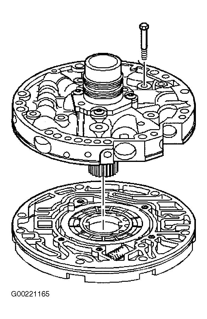
40 COMPONENT DISASSEMBLY & REASSEMBLY OIL PUMP Disassembly 1. Remove reverse input clutch drum-to-oil pump thrust washer, pump-to-case gasket and pump-to-case oil seal ring from pump assembly. See Fig. 34. Remove pump cover retaining bolts. Separate pump cover from pump body. See Fig. 35. WARNING: Pump slide spring and pressure relief spring rivet are under high pressure. To prevent possible injury, cover springs during removal. CAUTION: Keep pump vanes in installed position. If pump vanes are installed upside-down or backward, they will wear rapidly. 2. Using needle-nose pliers, compress pump slide spring. Remove from pump by pulling straight out. Remove pump vane rings, pump vanes, pump rotor and rotor guide from pump pocket. 3. Remove slide from pump pocket. Remove slide seal and seal support from pump slide. See Fig. 36. Remove pivot pin and pivot pin spring. Remove seal ring and "O" ring from pump slide. Remove seal retainer and seal from pump body. 4. Check condition of pump bushing. If bushing is in good condition, do not remove it. Push inward on converter clutch valve stop to compress spring. Remove snap ring. Remove valve stop, converter clutch apply valve and springs. 5. Using small punch, remove pressure relief spring retaining rivet. Remove relief spring and check ball. Remove oil screen and "O" ring from pump cover. Remove reverse boost valve sleeve. Remove reverse boost valve, pressure regulator valve spring and pressure regulator valve.
41
42 Fig. 34: Removing/Installing Thrust Washer & Oil Seal
43
44 Fig. 35: Removing/Installing Oil Pump Bolts & Cover Fig. 36: Exploded View Of Oil Pump Assembly Inspection 1. Inspect all valves, springs, sleeves and bushings for chips, burrs, distortion and free movement in bores. Check pressure relief check ball and spring for damage and distortion. Low line pressure will result if check ball and spring are damaged. 2. Inspect pump cover screen and "O" ring for wear and damage. Clean pump body and cover. Check all bores for obstructions. Inspect mating sides of cover and body for scoring, flatness and damage between channels. Check channels for dirt and damaged passages. Inspect stator shaft and pump body bushings for damage. 3. Inspect rotor and slide for scoring, cracks and damage. Check rotor guide and pump vane rings for excessive wear and damage. Inspect all seals for damage. 4. Measure pump rotor and slide thickness for surface wear. Rotor and slide measurements must fall into same thickness range. See OIL PUMP COMPONENT THICKNESS table. If rotor and slide measurements do not fall into same thickness range, or are outside of all ranges, oil pump must be replaced as an assembly.
45 OIL PUMP COMPONENT THICKNESS Component Thickness - In. (mm) Pump Rotor & Slide ( ) Reassembly 1. Install "O" ring and seal ring in groove on back side of pump slide. Retain seal ring using petroleum jelly. Install pivot pin and spring in pump body. Install pump slide. Notch in pump slide must align with pivot pin hole and with flat oil seal ring facing downward in pump pocket. Install slide seal and support. See Fig. 37. CAUTION: Keep pump vanes in installed position. If pump vanes are installed upside-down or backward, they will rapidly wear out. 2. Install pump vane ring into pump pocket. Coat rotor guide with petroleum jelly. Install rotor guide on rotor. Install rotor and guide into pump pocket with guide toward pump pocket. Install vanes in rotor. Install vane guide ring. Compress pump slide spring and install into pump pocket. All parts must be even with pump body surface. Install "O" ring on pump screen, and install screen in pump cover with "O" ring end out. 3. Install oil seal in pump body. Install seal retainer. Install pressure relief check ball and spring in pump cover. Install retaining rivet. Install converter clutch valve springs and converter clutch valve. Install valve stop and snap ring. Install pressure regulator valve and spring in pump cover. See Fig Coat reverse boost valve with petroleum jelly. Install reverse boost valve in boost valve sleeve with small end first. Install reverse boost valve sleeve in pump cover. 5. Install pump cover on pump body. Install retaining bolts finger tight. Align pump body and cover using Alignment Strap (J-21368). See Fig. 38. Place bolt through pump-to-case bolt hole. Tighten retaining bolts to specification. See TORQUE SPECIFICATIONS. Remove alignment strap. Position pump-to-case gasket on pump, and retain with petroleum jelly. 6. Install oil seal rings on stator hub. Place Stator Shaft Seal Installer (J ) over oil pump stator hub (stator support). See Fig. 39. Set height of installer tool to just above seal groove. Push seal ring over installer tool using Seal Pusher (J ). Install remaining seal rings. Place Stator Shaft Seal Sizer (J ) over stator hub and leave until oil pump installation. 7. Install pump-to-case oil seal on cover. Ensure seal is not twisted. Coat seal with ATF. Install pump-to-drum thrust washer. Ensure tangs on washer engage with holes in hub.
46 Fig. 37: Assembling Oil Pump Internal Components
47 Fig. 38: Installation Of Oil Pump Strap
48 Fig. 39: Installing Oil Pump Stator Hub Seal Rings REVERSE INPUT CLUTCH & FORWARD CLUTCH Disassembly 1. Remove the reverse input clutch housing and drum assembly from the input clutch assembly. Remove the stator/selective washer bearing assembly. Remove the selective thrust washer. Remove the 3rd and 4th clutch backing plate retainer ring. Remove all 3rd and 4th clutch plates. Remove the 3-4 clutch boost spring assemblies. See Fig. 28. NOTE: The 3rd and 4th clutch plate stack is different for 2.2L models. The M30 RPO 3-4 Clutch plate stack up is application specific. The stack up on a 2.2L S/T platform is 5 fiber plates, and 6 fiber plates on all other models. The M32 RPO (heavy-duty design) uses 7 fiber plates. These fiber plates are thinner thickness which can not be used in a M30 stack up. M32 fiber plates must
. Remove the forward clutch sprag assembly. See Fig. 42. 3. Remove all forward clutch plates (646, 648, 649A, 649B).")
49 Fig. 40: Removing Overrun Clutch Spring & Snap Ring 2001 Chevrolet Corvette not be used in a M30 design. 2. Remove the forward clutch backing plate retainer ring (651). Remove the forward clutch selective backing plate (650). Remove the forward clutch sprag assembly. See Fig Remove all forward clutch plates (646, 648, 649A, 649B). Remove the input sun gear bearing assembly (637). Remove the input housing to output shaft seal (636). Remove all overrun clutch plates (645A, 645B). See Fig Install the clutch spring compressor and adapter. Compress the overrun clutch spring using the clutch spring compressor and press. Remove the overrun clutch spring retainer snap ring (635). See Fig Remove the overrun clutch spring assembly (634). Remove the overrun clutch piston (632). Remove the forward clutch piston (630). Remove the forward clutch housing (628). Remove the 3rd and 4th clutch spring assembly (626). Remove the 3rd and 4th clutch apply ring (625). Remove the 3rd and 4th clutch piston (623). See Fig. 43.

50 Fig. 41: Removing Forward And Overrun Clutch Plates
51 Fig. 42: Removing Forward Clutch Sprag Assembly
52 Fig. 43: Removing 3rd, 4th, Forward And Overrun Clutch Assemblies Reassembly 1. Place input clutch housing with turbine shaft downward. Install 3-4 piston seals with lips facing away from hub. Install 3-4 piston in input housing. 2. Install 3-4 clutch apply ring. Install "O" ring seal in input clutch housing. Install forward clutch housing. Install seals on forward clutch piston with lips facing away from tangs. 3. Install forward clutch piston in forward clutch housing. Install 3-4 spring on 3-4 clutch apply ring. Install forward clutch assembly on 3-4 spring assembly. Align forward clutch piston legs with tangs of 3-4 apply ring. Install Seal Protector (J-29883) on input housing.
53 FORWARD CLUTCH BACKING PLATE SPECIFICATIONS 2001 Chevrolet Corvette 4. Install 3-4 apply ring and forward clutch assembly in input clutch housing. Hold apply ring tangs while installing. DO NOT allow forward clutch piston to separate from assembly. Ensure assembly is firmly seated. 5. Install Seal Protector (J-29883) on input housing. Install overrun clutch piston with hub facing upward. If fully seated, overrun piston should be 3/16" below top of snap ring groove in input housing hub. Install spring assembly on overrun clutch piston. Compress springs, and install snap ring. Install input housing seal. NOTE: Soak clutch plates in ATF before installation. Coat all seals and "O" rings with ATF. Coat thrust washers and bearings with petroleum jelly. 6. Install 4 overrun clutch plates, starting with steel plate. Align wide notches with case lugs. Install remaining clutch plates, alternating steel and composition plates. 7. Install bearing assembly on input clutch hub. Bearing inner race must face input housing hub. Ensure bearing is centered. Align clutch plate tabs. Install forward clutch sprag assembly in input housing. Align overrun clutch hub with clutch plates. 8. Install forward clutch apply plate in input housing. Install forward clutch waved plate. Ensure all plates are aligned with input housing tangs. Starting with steel plate, install clutch plates, alternating steel and composition plates. Install backing plate and snap ring. See Fig Using 2 feeler gauges, measure clearance between backing plate and snap ring. See Fig. 45. Ensure clearance is as specified. See FORWARD CLUTCH CLEARANCE SPECIFICATIONS table. If clearance is not as specified, install proper size backing plate with chamfered side upward. See FORWARD CLUTCH BACKING PLATE SPECIFICATIONS table. Install snap ring. FORWARD CLUTCH CLEARANCE SPECIFICATIONS Application Clearance - In. (mm) 9.650" (245 mm) ( ) Converter 258 mm Converter (1) 298 mm Converter ( ) 300 mm Converter ( ) (1) Specification is not available from manufacturer.
54 Identification Thickness - In. (mm) A ( ) B ( ) C ( ) D ( ) E ( ) Fig. 44: Installing Forward Clutch Assembly Components
55 Fig. 45: Measuring Forward Clutch Pack Clearance NOTE: Vehicles equipped with 2.2L engines use an additional thin steel plate between apply plate and fiber plate.
56 10. Install apply plate and 3-4 clutch plates. See Fig. 46. Install 3-4 clutch booster spring assemblies. See Fig. 47. Install backing plate with chamfered side upward. Install retaining snap ring. Using feeler gauge, measure clearance between backing plate and first composition plate. See Fig. 48. Clearance should be " ( mm). 11. If clearance is not as specified, select proper backing plate to obtain correct clearance. See 3-4 BACKING PLATE SPECIFICATIONS table. Air check all clutches at feed holes in turbine shaft. See Fig During overrun clutch test, air pressure will blow past forward clutch piston seals and exit out forward clutch feed hole in turbine shaft. Turbine shaft seals require sizing and should be installed before oil pump installation. Position Seal Installer (J B) on input shaft. See Fig. 50. Adjustment screw in seal installer must be adjusted to obtain correct height for each seal installation. Install 4 turbine shaft seals. 3-4 BACKING PLATE SPECIFICATIONS Identification Thickness - In. (mm) A ( ) B ( ) C ( )
57 Fig. 46: Installing 3-4 Clutch Assembly Components
58 Fig. 47: Locating 3-4 Clutch Booster Springs
59 Fig. 48: Measuring 3-4 Clutch Pack Clearance
60 Fig. 49: Air Checking Input Clutch Assembly
61 Fig. 50: Installing & Sizing Turbine Shaft Seals FORWARD CLUTCH SPRAG Disassembly 1. Remove the overrun clutch hub retaining snap ring (638). Remove the overrun clutch hub (639). Remove the forward sprag clutch inner race and input sun gear assembly (640). See Fig Remove the sprag assembly retainer rings (643). See Fig. 52.
62 5. Important The sun gear should only rotate in a counterclockwise direction. Hold the forward sprag clutch outer race with one hand and rotate the input sun gear with the other 2001 Chevrolet Corvette Inspection 1. Inspect sprag assembly for weak or damaged springs and retainers and worn rollers. Inspect overrun clutch hub for spline damage, excessive wear and open oil passages. Inspect retainer and race for spline damage, surface wear and damaged ring grooves. 2. Replace sprag assembly if damaged. Inspect forward clutch race for spline damage, excessive wear and open oil passages. Inspect input shaft and housing for spline damage, wear and open oil passages. 3. Inspect 3 sealing check balls located in rear of turbine shaft for tightness. Turbine shaft contains one open lubrication hole. Ensure orifice cup plug is installed. Inspect turbine shaft seal areas for roughness and burrs. 4. Inspect check ball located in input housing for free operation. Inspect pistons for wear, damage and porosity. Inspect spring assemblies for damage and distortion. 5. Inspect steel and composition plates for damage. Inspect snap rings for distortion and damage. Check backing plates for flatness and distortion. Inspect clutch apply rings for distortion and damaged tangs. 6. Inspect forward clutch housing check ball for proper operation (if equipped). Inspect housing for cracks and damage in seal areas. Inspect bearings for excessive wear, flatness, damage and flat rollers. Reassembly 1. Install the forward sprag assembly (642) into the forward clutch outer race (644). See Fig Install the sprag assembly retainer rings (643) into the forward clutch sprag assembly (644). See Fig Install the forward sprag clutch inner race and input sun gear assembly (640) into the forward sprag and outer race assembly. See Fig Install the overrun clutch hub (639) onto the sprag clutch inner race and input sun gear assembly (640). Install the overrun clutch hub retaining snap ring (638). See Fig. 56. NOTE: If the forward clutch sprag assembly operates backwards, you have installed the sprag backwards. Reassemble the sprag correctly. Test the forward clutch sprag assembly for proper operation. Position the forward clutch sprag assembly with the input sun gear facing up. See Fig. 57.
63 hand. Install the forward clutch sprag and input sun gear assembly into the input clutch housing. Index the overrun clutch hub into the overrun clutch plates. See Fig. 58.
64 Fig. 51: Disassembly Of Forward Clutch Sprag (1)
65
66 Fig. 52: Disassembly Of Forward Clutch Sprag (2) Fig. 53: Installing Forward Sprag Assembly
67 Fig. 54: Installing Sprag Assembly Retainer Ring
68 Fig. 55: Installing Inner Race & Input Sun Gear Assembly
69 Fig. 56: Installing Overrun Clutch Hub & Retaining Snap Ring Assembly
70 Fig. 57: Installing Forward Sprag Assembly Into Housing 2001 Chevrolet Corvette
71 Fig. 58: Installing & Checking Forward Clutch Sprag Assembly
72 LOW-REVERSE SUPPORT Disassembly & Inspection Remove inner race and snap ring. Remove roller clutch assembly. Check inner race for damage and surface finish. See Fig. 59. Inspect roller and springs for damage and distortion. Inspect support for loose cam, cracks and damaged surface finish. Replace damaged parts as necessary. Reassembly CAUTION: Note direction roller clutch is installed in support. Roller clutch must be installed in proper direction to provide lockup of inner race when rotated. 1. Install roller clutch assembly in low-reverse support. See Fig. 59. Place support in case with hub facing downward. Install inner race. Rotate inner race while pushing downward. Use care not to damage roller and springs during installation. 2. Ensure inner race is fully seated. Bottom tangs will be flush with carrier hub when fully seated. Inner race should rotate clockwise and lock counterclockwise with clutch hub downward. Insert support retainer spring into case between case lug and open notch in support.
73 1. Remove 4th apply piston and housing from 2nd apply piston assembly. Remove return spring from apply pin. Install Piston Compressor (J ) on 2nd apply piston. See 2001 Chevrolet Corvette Fig. 59: Exploded View Of Low-Reverse Clutch Assembly 2-4 SERVO ASSEMBLY Disassembly
74 Fig Compress 2nd servo apply piston assembly. Remove retainer ring. Separate 2nd apply piston, spring and retainer. Remove retainer ring, washer and spring from apply pin, and remove pin. Remove all oil seal rings. See Fig. 60.
75 Fig. 60: Exploded View Of 2-4 Servo Assembly Fig. 61: Compressing 2nd Apply Piston Inspection Inspect all pistons for porosity and damage. Check for ring groove damage and servo bore in case for any wear which may cut servo seals. Check all springs and oil seal rings for distortion and damage. Reassembly Different servo piston housings and 2nd apply pistons are used for different applications. If servo piston housing or 2nd apply piston is replaced, inside dimension of parts must be checked. Measure inside diameter of piston housing and 2nd apply piston. Dimension must be same as original. To reassemble, reverse disassembly procedure. Coat seals with petroleum jelly before assembly. VALVE BODY CAUTION: Valve springs can be tightly compressed. Use care when removing retainers and plugs. Personal injury could result.
76 Disassembly 1. Remove the manual valve (340). See Fig Remove the forward accumulator cover bolts (364) and the forward accumulator cover (363). Remove the forward accumulator spring (356), forward accumulator piston (354), and the forward accumulator pin (355). Remove the low overrun valve spring (362) and the low overrun valve (361). Remove the coiled spring pin (360) and the bore plug (359). Remove the forward abuse valve spring (358) and the forward abuse valve (357). See Fig Remove the solenoid retainer (395) and the 1-2 shift solenoid (367A). Remove the 1-2 shift valve (366) and the 1-2 shift valve spring (365). See Fig Remove the solenoid retainer (395) and the 2-3 shift solenoid (367B). Remove the 2-3 shuttle valve (369) and the 2-3 shift valve (368). See Fig Remove the coiled spring pin (360). Remove the 1-2 accumulator valve sleeve (372). Remove the 1-2 accumulator valve (371) and the 1-2 accumulator valve spring (370). See Fig Remove the solenoid retainer bolt (364A) and the solenoid retainer (378). Remove the pressure control solenoid (377). Compress the actuator feed limit valve spring (375). Remove the bore plug retainer (395) and release the spring slowly. Remove the bore plug (376). Remove the actuator feed limit valve spring (375) and the actuator feed limit valve (374). See Fig Remove the solenoid retainer (395) and the 3-2 control solenoid (394). Remove the 3-2 control valve (391) and the 3-2 control valve spring (392). See Fig Remove the bore plug retainer (395) and the bore plug (381). Remove the 3-2 downshift valve spring (390) and the 3-2 downshift valve (389). Remove the coiled spring pin (360) and the bore plug (359). Remove the reverse abuse valve spring (388) and the reverse abuse valve (387). See Fig Remove the bore plug retainer (395) and the bore plug (381). Remove the 3-4 shift valve spring (386) and the 3-4 shift valve (385). See Fig Remove the bore plug retainer (395) and the bore plug (381). Remove the regulator apply valve (380) and the regulator apply spring (397) and the isolator valve (398). See Fig Remove the bore plug retainer (395) and the bore plug (381). Remove the 3-4 relay valve (384) and the 4-3 sequence valve (383) and the 4-3 sequence valve spring (382). See Fig. 72. Inspection Inspect valves and sleeves for scoring and cracks. Ensure valves move freely in bores. Inspect
77 valve body for cracks and scored bores. Inspect machined surfaces for damage. Inspect springs for damaged coils. Replace damaged parts as necessary. Reassembly NOTE: NOTE: Lubricate all parts with Dexron(R)-lll automatic transmission fluid before installation. For Reassembly procedures, reverse the disassembly of the valve body in this section. See VALVE BODY Fig. 62: Removing/Installing Manual Valve
78 Fig. 63: Removing/Installing Forward Accumulator & Overrun Assembly
79 Fig. 64: Removing/Installing 1-2 Shift Solenoid Assembly
80 Fig. 65: Removing/Installing 2-3 Shift Solenoid Assembly
81 Fig. 66: Removing/Installing 1-2 Accumulator Assembly
82 Fig. 67: Removing/Installing Pressure Control Solenoid
83 Fig. 68: Removing/Installing 3-2 Control Solenoid Assembly
84 Fig. 69: Removing/Installing 3-2 Downshift Valve Assembly
85 Fig. 70: Removing/Installing 3-4 Shift Valve Assembly

86 Fig. 71: Removing/Installing Regulator Apply Valve Assembly
87 Fig. 72: Removing/Installing 3-4 Relay Valve & 4-3 Sequence Valve TRANSMISSION CASE Cleaning & Inspection Clean transmission case and dry with compressed air. Inspect case assembly for damage, cracks and damaged bolt hole threads. Inspect valve body surface for flatness and land damage. Check case oil passages for restrictions and blockage. Blow compressed air through all case passages. See Fig. 73. Inspect case internal clutch plate lugs for damage and wear. Inspect servo and accumulator bores for damage. Inspect all snap ring grooves for damage.
88 Fig. 73: Identifying Transmission Case Fluid Passages REACTION & INPUT GEAR SETS, LOW-REVERSE CLUTCH & SUPPORT Cleaning & Inspection 1. Clean all parts and dry with compressed air. Inspect reaction and input carriers for pinion gear damage, excessive wear and improper staking of pinion pins. Inspect carrier bearings for heat damage, flatness and roller condition. Place output shaft sleeve inside reaction carrier and input carrier. 2. Rotate sleeve and note smoothness of bearing operation. Replace carrier assembly if roughness is felt. Check pinion gear end play on reaction and input carriers. See Fig Pinion gear end play should be " ( mm). Inspect internal reaction gear and support for cracks and damaged splines. Inspect low-reverse clutch plates for wear and signs of excessive heat. 4. Inspect low-reverse clutch piston for roughness or damage in seal ring area. Inspect retainer ring and spring assembly for damage. Inspect sun and internal gears and supports for spline
89 and bushing wear and damage. Replace damaged parts as necessary. Fig. 74: Measuring Input Carrier Pinion Gear End Play MISCELLANEOUS CASE COMPONENTS Cleaning & Inspection Clean all parts and dry with compressed air. Inspect 1-2 and 3-4 accumulator parts for damage to pistons or housing. Inspect for flatness and condition of accumulator, oil passage plate and gasket. Inspect wiring harness leads and connectors for damage. Inspect speed sensor rotor teeth for damage and distortion. TRANSMISSION REASSEMBLY NOTE: To identify bushing, seal, thrust bearing and thrust washer locations and direction, refer to appropriate illustration. See Fig. 85 and Fig. 86. LOW-REVERSE CLUTCH
90 1. Place transmission in a vertical position. Install seals on low-reverse clutch piston. Apply petroleum jelly to seals. Align and install piston with notch in bottom of transmission case (695). Ensure piston is fully seated and parking pawl aligns with opening in piston wall. See Fig. 75. Install the low and reverse clutch spring assembly (694). Using the Clutch Spring Compressor (J ), compress the low and reverse clutch spring assembly (694). Using the Snap Ring Remover and Installer (J36850), install the low and reverse clutch retainer ring (693). See Fig Coat bearing assembly with petroleum jelly. Install bearing assembly on case hub with outside bearing race toward case hub. Install internal reaction gear and support. Install bearing assembly onto support with outside bearing race toward support. Install oil deflector (if equipped) and reaction carrier assembly in case. See Fig Place waved plate on work bench. Install 5 composition plates and 4 steel plates alternately, starting with composition plate. Install low-reverse support. Apply light pressure to lowreverse support. Do not flatten waved plate. Measure height of clutch pack from work bench to top of low-reverse support. See Fig Using height dimension, determine proper selective spacer plate to be used. See SPACER PLATE SELECTION table. SPACER PLATE SELECTION Measured Clutch Pack Height - In. (mm) (1) Plate Thickness - Identification In. (mm) ( None ( ) 1.85) ( "0" ( ) 1.31) ( "1" ( ) 2.34) (1) Clutch pack height is measured without spacer plate in position. 5. Place spacer plate between waved plate and first composition plate with identification facing upward. Measure overall height of clutch pack. Overall height should be " ( mm). Install low-reverse clutch pack into transmission case. Ensure clutch plates align with splines of reaction carrier. Ensure steel plates are properly indexed in transmission case. See Fig Install low-reverse support in case with hub downward. Install inner race by pushing
91 downward while rotating until it is fully engaged. Bottom tangs will be flush with hub when fully installed. Install spring retainer in case between case lug and open notch in support. Install low-reverse snap ring. See Fig. 79
92 Fig. 75: Installing Low-Reverse Clutch Piston Fig. 76: Installing Low-Reverse Clutch Spring Assembly
93 Fig. 77: Measuring Low-Reverse Clutch Pack Stack Height
94 Fig. 78: Installing Low-Reverse Clutch Steel Plates
95 1. Install retainer ring on reaction sun gear (if removed). Install sun gear into reaction carrier. Install thrust washer on low-reverse clutch race. Install reaction sun gear shell on reaction sun gear Chevrolet Corvette Fig. 79: Installing Low-Reverse Clutch Support REACTION & INPUT GEAR SETS
96 2. Install thrust washer on reaction sun gear shell. Ensure thrust washer tangs engage on gear shell. Install input internal gear and reaction carrier shaft in sun gear shell. Carrier shaft splines must engage with reaction carrier. See Fig Install thrust washer on reaction carrier shaft. Outer race must face toward reaction carrier shaft. Install output shaft in transmission. Ensure output shaft engages with all parts. 4. Install Output Shaft Support (J A). See Fig. 7. Adjust support so output shaft is positioned upward as far as possible. Install input carrier (planetary) assembly with hub end down on output shaft. Install NEW retainer ring on output shaft. Remove output shaft support. Install input sun gear, indexing gear end with input carrier pinions. REVERSE INPUT ASSEMBLY & INPUT CLUTCH 1. Install the selective thrust washer (616) on the input housing (621). Install the stator shaft/selective washer bearing assembly (615) on the input housing (621). The black race on the bearing goes toward the oil pump. Install the reverse input clutch assembly (605) on the input housing (621). Index the reverse input clutch plates with the input clutch hub. Make certain all clutch plates are fully engaged. See Fig Install reverse and input clutch assemblies in transmission case as an assembly. Align 3-4 clutch plates of input assembly with input internal gear. Assembly is fully seated when reverse input clutch housing is just below oil pump face of case. See Fig. 81.
97 Fig. 80: Installing Reverse & Input Clutches Components
98 Fig. 81: Installing Reverse & Input Clutches Into Transmission Case OIL PUMP ASSEMBLY 1. Ensure turbine shaft seals on input shaft have been sized using Seal Sizer (J A). See
99 Fig. 50. Install aligning pins in 2 opposing pump bolt holes in transmission case. Ensure thrust washer is installed on rear of oil pump. Thrust washer can be retained using petroleum jelly. 2. Remove input shaft Seal Sizer (J A). Remove Stator Shaft Seal Sizer (J ). Install oil pump into case, aligning filter and pressure regulator holes with holes in case. Install retaining bolts. Tighten bolts to specification. See TORQUE SPECIFICATIONS. Place transmission in a horizontal position. 3. Turbine shaft should rotate by hand. If turbine shaft will not rotate, loosen pump retaining bolts and attempt to rotate shaft again. If shaft now turns, reverse and input assemblies have not been indexed properly or some other assembly problem has occurred, such as thrust washer not positioned properly. 4. Check transmission end play. See TRANSMISSION END PLAY CHECK. Transmission end play should be " ( mm). Install torque converter. Ensure converter hub is aligned with oil pump. Install torque converter retaining strap to hold converter. 2-4 BAND & SERVO ASSEMBLY 1. Install 2-4 band in case. Align band anchor pin end with case pin hole. Install band anchor pin in case. See Fig. 25. Ensure band anchor pin aligns with end of 2-4 band. 2. Install 2-4 servo assembly into case, and index apply pin on band end. Check for proper engagement of apply pin on band end. Recheck 2-4 servo apply pin selection to ensure correct pin is installed. 3. Remove 4th apply piston and return spring. See Fig. 60. Remove retainer ring, washer, apply pin spring and 2nd apply pin. Install Piston Compressor (J ) on 2nd apply piston. See Fig Remove retainer ring, cushion spring and spring retainer. Install Band Apply Pin Tool (J ) and apply pin. See Fig. 82. Apply 100 INCH lbs. (11 N.m) torque. 5. White line on band apply tool should be within gauge slot if pin length is correct. If White line is not within gauge slot, inspect 2-4 band and reverse input drum for wear and damage during disassembly. 6. Servo pin length must be checked during reassembly. Servo pin is preset and must not be readjusted. Different length servo pins are available. See SERVO PIN SPECIFICATIONS table. Select proper length servo pin. Reassemble 2-4 servo. Install servo cover and "O" ring. Compress cover and install cover retaining ring. Index ends of retaining ring with slot in case. SERVO PIN SPECIFICATIONS Identification Grooves Pin Length - In. (mm)
100 OIL PUMP THRUST WASHER SPECIFICATIONS 2001 Chevrolet Corvette ( ) ( ) None ( ) Fig. 82: Measuring Servo Pin Length TRANSMISSION END PLAY CHECK 1. Install Pump Remover/End Play Fixture (J A) and End Play Adapter (J A) on end of turbine shaft. See Fig. 83. Clamp dial indicator on long bolt with indicator tip on end play fixture. Zero dial indicator. 2. Pull up on end play fixture. Measure transmission end play. Transmission end play should be " ( mm). If transmission end play is not within specification, selective thrust washer must be changed between oil pump and input housing. See Fig. 28. Install appropriate thrust washer, and recheck end play. See OIL PUMP THRUST WASHER SPECIFICATIONS table.
101 ID No. Thickness - In. (mm) ( ) ( ) ( ) ( ) ( ) ( ) ( ) ( ) Fig. 83: Measuring Transmission End Play VALVE BODY, 1-2 & 3-4 ACCUMULATORS
102 CAUTION: If spacer plate and gasket replacement is required, ensure NEW spacer plate and gasket are identical to those removed. 1. Install 3-4 accumulator piston pin in case. Install 3-4 piston seal on piston. Install 3-4 accumulator piston on pin. Legs of piston must face valve body. 2. Install 3-4 accumulator spring. Install oil screens in proper locations. See Fig. 84. See Fig. 17 for check ball and filter installation locations. Install alignment pins in transmission case to aid spacer plate and valve body installation. Install spacer plate gasket and spacer plate. Install spacer plate support. 3. Install 1-2 accumulator spring, oil seal ring and 1-2 accumulator piston. Install accumulator cover and bolts. Tighten bolts to specification. See TORQUE SPECIFICATIONS. 4. Coat check balls with petroleum jelly. Install check balls in proper locations in valve body. See Fig. 16 and Fig. 17. Install manual valve link. Ensure manual valve link is properly seated in manual valve. See Fig. 15. Improper positioning may prevent vehicle operation in "D" range. NOTE: Improper positioning of throttle valve link will result in erratic shift points or high oil pressure. 5. Install valve body and retaining bolts. Ensure correct length and location of bolts. See Fig. 14. Install detent spring. Install detent spring bolt. Install transmission fluid pressure manual valve position switch. Install TCC solenoid. Install valve body bolts that secure wiring harness. Tighten all valve body bolts to specification. See TORQUE SPECIFICATIONS. 6. Install TCC PWM solenoid. Install retainer clip. Install electrical connectors to switches and solenoids. See Fig. 8. Install oil filter and "O" ring. Install transmission oil pan.
103 1. Install speed sensor rotor retaining clip on output shaft. Install "O" ring in output shaft sleeve. Install output shaft sleeve on output shaft. DO NOT position output shaft sleeve past machined surface of output shaft. Install seal ring on extension housing. 2. Position extension housing on transmission case. Install retaining bolts. Install oil seal in extension housing. Install speed sensor assembly. Install retainer and bolt. Tighten bolt to specification. Install outside electrical connector. Install PNP switch and manual shift lever. See PARK/NEUTRAL POSITION SWITCH under REMOVAL & INSTALLATION Chevrolet Corvette Fig. 84: Locating Oil Screens EXTENSION HOUSING
104 Fig. 85: Identifying 4L60-E Oil Seal Locations
 Converter Housing Bolt (Except Corvette) 55 (75) Detent Spring-To-Valve Body Bolt 20 (27) Extension Housing Bolt 35 (48) Manual Shaft-To-Detent Lever Nut 25 (34) Oil Cooler Pipe Connector 30 (41)")
105 Fig. 86: Identifying 4L60-E Bushing, Thrust Bearing & Thrust Washer Locations TORQUE SPECIFICATIONS TORQUE SPECIFICATIONS Application Ft. Lbs. (N.m) Converter Housing Bolt (Except Corvette) 55 (75) Detent Spring-To-Valve Body Bolt 20 (27) Extension Housing Bolt 35 (48) Manual Shaft-To-Detent Lever Nut 25 (34) Oil Cooler Pipe Connector 30 (41) Oil Cooler Pipe Fitting 30 (41) Oil Pan Drain Plug Corvette 24 (32) Except Corvette 30 (40) Oil Pump Cover-To-Body Bolt 20 (27) Oil Pump-To-Case Bolt 24 (32) Park Bracket-To-Case Bolt 25 (34)
106 Torque Converter-To-Flexplate Bolt 44 (60) Transmission Case Extension Bolt (Corvette) 16 (22) INCH Lbs. (N.m) Accumulator Cover-To-Case Bolt 124 (14) Forward Accumulator Cover-To-Valve Body Bolt 124 (14) Line Pressure Plug 124 (14) Oil Pan-To-Case Bolt 124 (14) Oil Passage Cover Bolt 124 (14) PC Solenoid Bracket-To-Valve Body Bolt 124 (14) Speed Sensor Bolt 124 (14) TCC Solenoid Assembly-To-Case Bolt 124 (14) TFP Manual Valve Position Switch-To-Valve Body Bolt 124 (14) Valve Body-To-Case Bolt (1) 124 (14) (1) Tighten valve body bolts in a spiral pattern starting in center of valve body. TRANSMISSION SPECIFICATIONS TRANSMISSION SPECIFICATIONS Application Clearance In. (mm) Forward Clutch (1) W/9.650" (245 mm) Converter ( ) W/11.732" (298 mm) Converter ( ) W/11.811" (300 mm) Converter ( ) Reverse Input Clutch ( ) 3-4 Clutch ( ) End Play Reaction & Input Planetary Pinion Gear ( ) Torque Converter 9.650" (245 mm) (0-.38) " (258 mm) ( ) " (298 mm) (0-.48) " (300 mm) ( ) Transmission ( )
107 Height (Low-Reverse Clutch) ( ) (1) Forward clutch clearance specification for transmissions equipped with 258 mm torque converter is not available from manufacturer.
AUTOMATIC TRANSMISSIONS. General Motors Corp. Hydra-Matic 4L60-E Overhaul
 1997-98 AUTOMATIC TRANSMISSIONS General Motors Corp. Hydra-Matic 4L60-E Overhaul APPLICATION TRANSMISSION APPLICATIONS Application Corvette Transaxle 4L60-E IDENTIFICATION The 4L60-E transmission can be
AUTOMATIC TRANSMISSIONS Mitsubishi F3A20 Series TRANSMISSION APPLICATION TABLE
 Article Text ARTICLE BEGINNING AUTOMATIC TRANSMISSIONS Mitsubishi F3A20 Series APPLICATION TRANSMISSION APPLICATION TABLE Vehicle Application Transmission Model Colt 3-Speed (1990-94)... F3A21 Colt Vista
2005 Toyota RAV AUTOMATIC TRANSMISSIONS U240E & U241E Overhaul
 2001-05 AUTOMATIC TRANSMISSIONS U240E & U241E Overhaul APPLICATION CAUTION: Flush oil cooler and oil cooler lines prior to transaxle installation. Oil cooling system contamination may cause premature transaxle
COMPONENT LOCATOR > DISASSEMBLED VIEWS
 Page 1 of 26 Service Manual: AUTOMATIC TRANSAXLE - 4T65-E - OVERHAUL COMPONENT LOCATOR > DISASSEMBLED VIEWS Fig 1: Case and Associated Parts Disassembled View (1 of 4) 2004 Buick LeSabre 3.8L Eng Limited
2002 F-Super Duty /Excursion Workshop Manual
 Page 1 of 25 SECTION 307-01: Automatic Transaxle/Transmission 2002 F-Super Duty 250-550/Excursion Workshop Manual ASSEMBLY Procedure revision date: 05/23/2001 Transmission Special Tool(s) Remover, O-Ring
Geo Prizm ( LSi) Toyota Celica 1.8L (1994)
 Toyota Celica 1.8L (1994)") Page 1 of 140 ARTICLE BEGINNING APPLICATION TRANSMISSION APPLICATIONS Application Geo Prizm (1993-94 LSi) Toyota Celica 1.6L (1993) Celica 1.8L (1994) Celica 2.2L (1993) Corolla 1.8L MR2 Paseo Transaxle
Page 1 of 140 ARTICLE BEGINNING APPLICATION TRANSMISSION APPLICATIONS Application Geo Prizm (1993-94 LSi) Toyota Celica 1.6L (1993) Celica 1.8L (1994) Celica 2.2L (1993) Corolla 1.8L MR2 Paseo Transaxle
Related Service Documents
 #07-07-30-024: Information on 4L60-E M30 Rear Wheel Drive Automatic Transmission Valve Body Reconditioning, DTC P0741, P0756, P0894, Harsh 1-2 Shift - (Sep 27, 2007) Subject: Information on 4L60-E M30
 Page 1 of 22 SECTION 307-01: Automatic Transaxle/Transmission 4R70E/4R75E ASSEMBLY Procedure revision date: 05/29/2009 Transmission Printable View (1554 KB) Special Tool(s) Air Test Plate, Transmission
MANUAL TRANS OVERHAUL - BORG-WARNER - T56 6-SPEED MANUAL TRANSMISSIONS Borg-Warner T56 (MM6) 6-Speed
 6-Speed") IDENTIFICATION MANUAL TRANS OVERHAUL - BORG-WARNER - T56 6-SPEED 1998 MANUAL TRANSMISSIONS Borg-Warner T56 (MM6) 6-Speed Transmission has 2 identification labels, located on lower left side of case. One
IDENTIFICATION MANUAL TRANS OVERHAUL - BORG-WARNER - T56 6-SPEED 1998 MANUAL TRANSMISSIONS Borg-Warner T56 (MM6) 6-Speed Transmission has 2 identification labels, located on lower left side of case. One
ASSEMBLY. Transmission Automatic Transaxle/Transmission. Special Tool(s) Alignment Set, Fluid Pump 307-S039 (T74P X) Special Tool(s)
 Alignment Set, Fluid Pump 307-S039 (T74P X) Special Tool(s)") 307-01-1 Automatic Transaxle/Transmission 307-01-1 ASSEMBLY Transmission Special Tool(s) Adjustment Set, Transmission Band 307-S022 (T71P-77370-A) Special Tool(s) Alignment Set, Fluid Pump 307-S039 (T74P-77103-X)
307-01-1 Automatic Transaxle/Transmission 307-01-1 ASSEMBLY Transmission Special Tool(s) Adjustment Set, Transmission Band 307-S022 (T71P-77370-A) Special Tool(s) Alignment Set, Fluid Pump 307-S039 (T74P-77103-X)
ASSEMBLY. Transmission Automatic Transmission 5R44E and 5R55E. Special Tool(s)
") 307-01-1 Automatic Transmission 5R44E and 5R55E 307-01-1 ASSEMBLY Transmission Special Tool(s) Holding Fixture, Transmission 307-262 (T93T-77002-AH) Special Tool(s) Installer, Transmission Extension Housing
307-01-1 Automatic Transmission 5R44E and 5R55E 307-01-1 ASSEMBLY Transmission Special Tool(s) Holding Fixture, Transmission 307-262 (T93T-77002-AH) Special Tool(s) Installer, Transmission Extension Housing
2003 E-Series Workshop Manual
 Page 1 of 20 SECTION 307-01B: Automatic Transmission 4R70W 2003 E-Series Workshop Manual ASSEMBLY Procedure revision date: 04/27/2006 Transmission Printable View (1828 KB) Special Tool(s) Dial Indicator
ASSEMBLY PROCEDURE AUTOMATIC TRANSMISSION 5A-173. Transmission
 AUTOMATIC TRANSMISSION 5A-173 ASSEMBLY PROCEDURE Transmission Tools Required 0555-336256 Transmission Bench Cradle 0555-336258 Cross Shaft Pin Remover/Installer (Detent Lever) 0555-336262 Cross Shaft Seal
NOTE: Clean and inspect all components. Replace any components which show evidence of excessive wear or scoring.
 ASSEMBLY (AUTOMATIC 545RFE)... ASSEMBLY NOTE: Apply trans jell or petroleum jelly to all slide portions, rolling contacts surfaces, thrust surfaces etc. to prevent burnout during initial operation. Lubricate
 Page 1 of 10 Main Components and Functions Torque Converter 1 Cover (Part of 7902) 2 Converter Damper Plate 3 O-Ring (Part of 7902) 4 Turbine Assembly (Part of 7902) 5 Selective Spacer 6 Thrust Washer
ASSEMBLY PROCEDURE. Transmission
 67 ASSEMBLY PROCEDURE Transmission Tools Required 0555-336256 Transmission Bench Cradle 0555-336258 Cross Shaft Pin Remover/Installer (Detent Lever) 0555-336262 Cross Shaft Seal Installer 0555-336263 Cross
DISASSEMBLY AND ASSEMBLY
 307-01-1 Automatic Transaxle/Transmission 307-01-1 DISASSEMBLY AND ASSEMBLY Transaxle Special Tool(s) Dial Indicator Gauge With Holding Fixture 100-002 (TOOL-4201-C) Special Tool(s) Test Plate Screw Set,
NOTE: Clean and inspect all components. Replace any components which show evidence of excessive wear or scoring.
 21 - Transmission and Transfer Case/Automatic - 68RFE/Assembly ASSEMBLY Labor Operations: Click to display a list of Labor Operations associated with this procedure Special Tools: Click to display a list
Assembly. NOTE: Before beginning assembly, perform/inspect the following:
 Page 1 of 31 Home Account Contact ALLDATA Log Out Help DAN GRIMWOOD DAN GRIMWOOD00002 Select Vehicle New TSBs Technician's Reference Component Search: OK 1997 Ford Truck F 150 2WD Pickup V6-4.2L VIN 2
Transaxle. 1. Mount the transaxle to Bench Mounted Holding Fixture T57L-500-B.
 «1997 Aspire Table of Contents» «Group 07: TRANSAXLE» «Section 07-01: Transaxle, Automatic» «DISASSEMBLY» Transaxle CAUTION: To prevent dirt from entering the transaxle, it should be disassembled and kept
HIGH PERFORMANCE TRANSMISSION PARTS Instructions. Line Pressure Booster Kit. TCC Control Plunger Valve Kit. Line Pressure Modulator Plunger Valve Kit
 Performance Pack Ford 4R100 Part No. HP-4R100-01 Line Pressure Booster Kit Line-to-Lube Pressure Regulator Valve Line Pressure Booster Kit Valve Sleeve O-Rings (2) TCC Control Plunger Valve Kit Front Lube/Drainback
2000 Jeep Truck Cherokee 4WD L6-4.0L VIN S
 2000 Jeep Truck Cherokee 4WD L6-4.0L VIN S Vehicle» Transmission and Drivetrain» Automatic Transmission/Transaxle» Service and Repair» 30-40LE (AW4) 4 Speed» Overhaul (Transmission)» Disassembly DISASSEMBLY
1989 Jeep Cherokee. STEERING COLUMN' '1989 STEERING Jeep Steering Columns STEERING COLUMN STEERING Jeep Steering Columns
 STEERING COLUMN 1989 STEERING Jeep Steering Columns DESCRIPTION All models use collapsible steering columns. All columns have integral ignition switch and locking device. Optional tilt wheel is available
46RE, 46RH, 47RE, 47RH ZIP KIT
 46RE, 46RH, 47RE, 47RH ZIP KIT PART NUMBER 46-47RHE-ZIP QUICK GUIDE Parts are labeled here in order of installation. See other side of sheet for details on Zip Kit contents. installation Diagram 7 1 Separator
AUTOMATIC TRANSMISSIONS ZF 4HP 18
 AUTO TRANS OVERHAUL - ZF 4HP 18 Article Text 1991 Eagle Premier For Dan's Transmission Service 10 Jefferson Place Fort Walton Beach FL 32548 1997 Mitchell Repair Information Company, All Rights Reserved.
ABBREVIATIONS USED IN THIS
 IN10 INTRODUCTION ABBREVIATIONS USED IN THIS MANUAL ABBREVIATIONS USED IN THIS MANUAL ATF Automatic Transmission Fluid B 0 Overdrive Brake B 2 Second Brake B 3 No. 3 Brake C 0 Overdrive Direct Clutch C
Jatco 5 Speed ATRA. All Rights Reserved. Printed in U.S.A.
 1 2 3 Table Of Contents Transmission Diassembly... 4 Front Pump... 16 Reverse/High Clutch Drum... 18 Direct Clutch Drum... 22 Low Clutch Drum... 26 Planetary Gearsets... 29 Transfer Gear/Reduction Gear...
DISASSEMBLY. Transmission. All vehicles
 307-01-1 Automatic Transmission 5R44E and 5R55E 307-01-1 DISASSEMBLY Transmission Special Tool(s) Holding Fixture, Transmission 307-262 (T93T-77002-AH) Special Tool(s) Remover, Servo 307-347 (T97T-7D021-A)
TRANSMISSION PARTS Instructions
 TRANSMISSION PARTS Instructions Sure Cure Kit Part No. SC-4T65E GM 4T65-E Valve Body Parts Boost Valve Kit 84754-30K Patent No. 6,832,632 TCC Apply Valve Kit 84754-43K Patent No. 7,100,753 TCC Regulated
TRANSMISSION PARTS Instructions. Solenoid Regulator Valve Retainer Shim. Main Pressure Regulator Valve
 TRANSMISSION PARTS Instructions Sure Cure Kit Part No. SC-AODE NOTE: This kit is fully compatible with '91 '95 only. Identified by alignment pins 13mm heads. This kit will not work on '96 Later units.
1 of 25 9/12/2013 9:07 PM
 1 of 25 9/12/2013 9:07 PM 46RE Automatic Transmission DISASSEMBLY 1. Clean exterior of transmission with suitable solvent or pressure washer. 2. Place transmission in vertical position. 3. Measure the
AODE ( 96 & LATER) SC-AODE-1. Transmission Reconditioning Kit FULL COMPATIBILITY IMPORTANT VALVE BODY PARTS REASSEMBLY PARTS
 SC-AODE-1. Transmission Reconditioning Kit FULL COMPATIBILITY IMPORTANT VALVE BODY PARTS REASSEMBLY PARTS") AODE ( 96 & LATER) Transmission Reconditioning Kit FULL COMPATIBILITY SC-AODE-1 Full compatibility with 1996 and later units. Identified by alignment pins with 10mm head and.173" pin diameter. IMPORTANT
AODE ( 96 & LATER) Transmission Reconditioning Kit FULL COMPATIBILITY SC-AODE-1 Full compatibility with 1996 and later units. Identified by alignment pins with 10mm head and.173" pin diameter. IMPORTANT
Direct Clutch Assembly 1263
 SECTION 307-01: Automatic Transaxle/Transmission 2006 F-53 Motorhome Chassis TorqShift Workshop Manual DISASSEMBLY AND ASSEMBLY OF SUBASSEMBLIES Procedure revision date: 11/29/2004 Direct Clutch Assembly
DIFFERENTIALS & AXLE SHAFTS
 DIFFERENTIALS & AXLE SHAFTS 2001 Chevrolet Camaro 2000-01 DRIVE AXLES General Motors Differentials & Axle Shafts Chevrolet; Camaro Pontiac; Firebird DESCRIPTION & OPERATION Drive axle is a semi-floating,
AUTOMATIC TRANSAXLE AUTOMATIC TRANSAXLE SYSTEM... COMPONENT PARTS...
 SYSTEM....... COMPONENT PARTS.................... OIL PUMP.............................. DIRECT CLUTCH........................ FORWARD CLUTCH..................... SECOND BRAKE........................ UNDERDRIVE
DRIVE AXLE Volvo 960 DESCRIPTION & OPERATION AXLE IDENTIFICATION DRIVE AXLES Volvo Differentials & Axle Shafts
 DRIVE AXLE 1994 Volvo 960 1994 DRIVE AXLES Volvo Differentials & Axle Shafts 960 DESCRIPTION & OPERATION All 960 station wagon models use type 1041 rear axle assembly. All 960 4-door models use type 1045
SECTION 5B MANUAL TRANSMISSION TABLE OF CONTENTS
 SECTION 5B MANUAL TRANSMISSION TABLE OF CONTENTS General Description and Operation... 5B-2 Shift Lever... 5B-2 Transmission Assembly... 5B-2 Specifications... 5B-3 Diagnostic Information and Procedures...
REPAIR INSTRUCTIONS ON-VEHICLE SERVICE TRANSMISSION AUTOMATIC TRANSMISSION 5A-159. Removal and Installation Procedure
 REPAIR INSTRUCTIONS YAD5A080 AUTOMATIC TRANSMISSION 5A-159 ON-VEHICLE SERVICE TRANSMISSION Removal and Installation Procedure 1. Disconnect the negative battery cable. 2. Disconnect the connectors from
DISASSEMBLY TRANSAXLE DISASSEMBLY AND ASSEMBLY. Part 1 Of 3
 2004 Mitsubishi Truck Endeavor V6-3.8L SOHC Vehicle > Transmission and Drivetrain > Automatic Transmission/Transaxle > Service and Repair > Overhaul > F4A5A > Disassembly and Assembly DISASSEMBLY TRANSAXLE
GM 4L80-E, 4L85-E SURE CURE KIT
 GM 4L80-E, 4L85-E SURE CURE KIT PART NUMBER SC-4L80E INSTALLATION GUIDE Parts are labeled here in order of installation. See page 2 for details on Sure Cure kit contents. See Sure Cure instruction booklet
GM 4L80-E, 4L85-E SURE CURE KIT
 GM 4L80-E, 4L85-E SURE CURE KIT PART NUMBER SC-4L80E INSTRUCTION BOOKLET Parts are labeled here in order of installation. See page 2 for details on Sure Cure kit contents. See Sure Cure instruction booklet
2013 NATEF Task Area A-2 Automatic Transmission7-2013
 2013 NATEF Task Area A-2 Automatic Transmission7-2013 A. General Transmission & Transaxle Diagnosis B. Transmission & Transaxle Maintenance & Adjustment C. In-Vehicle Transmission & Transaxle Repair D.
Torqueflite Manual/Automatic Valve Body
 TCI 122400 Torqueflite Manual/Automatic Valve Body This valve body can be installed in a few hours by carefully following directions. Read all instructions first to familiarize yourself with the parts
Installation Instructions for TCI Turbo 700R TCI Turbo 700R
 Installation Instructions for TCI 378805 Turbo 700R4 1982-1984 TCI 378905 Turbo 700R4 1985-1993 KIT INTRODUCTION Read all instructions first to familiarize yourself with the parts and procedures. Work
Maintenance Information
 16575243 Edition 2 October 2013 Air Screwdrivers 1R Series Maintenance Information Save These Instructions Product Safety Information WARNING Failure to observe the following warnings, and to avoid these
This file is available for free download at
 This file is available for free download at http://www.iluvmyrx7.com This file is fully text-searchable select Edit and Find and type in what you re looking for. This file is intended more for online viewing
TH400(M40) 3L80 TH375 - TH475 3L80HD
 3L80 TH375 - TH475 3L80HD") A B C D 34 44 2008 Transtar Industries, Inc. No part of this work, including but not limited to the Part Numbers, may be reproduced or transmitted in any form or by any means, electronic or mechanical,
A B C D 34 44 2008 Transtar Industries, Inc. No part of this work, including but not limited to the Part Numbers, may be reproduced or transmitted in any form or by any means, electronic or mechanical,
Maintenance Information
 04581245 Edition 2 May 2014 Air Grinder, Die Grinder and Sander Series G2 (Angle) Maintenance Information Save These Instructions Product Safety Information WARNING Failure to observe the following warnings,
A/C COMPRESSOR SERVICING Article Text 1991 Saab 9000 For Copyright 1997 Mitchell International Friday, October 15, :22PM
 Article Text ARTICLE BEGINNING 1991 GENERAL SERVICING Compressor Service * PLEASE READ THIS FIRST * CAUTION: When discharging air conditioning system, use only approved refrigerant recovery/recycling equipment.
SECTION Automatic Transaxle/Transmission 6R80
 307-01-i Automatic Transaxle/Transmission 6R80 307-01-i SECTION 307-01 Automatic Transaxle/Transmission 6R80 CONTENTS PAGE Transmission... 307-01-2 307-01-2 Automatic Transaxle/Transmission 6R80 307-01-2
2012 NATEF Task Area A 2 Automatic Transmission
 2012 NATEF Task Area A 2 Automatic Transmission A. General Transmission & Transaxle Diagnosis B. Transmission & Transaxle Maintenance & Adjustment C. In Vehicle Transmission & Transaxle Repair D. Off Vehicle
EATON 751, 781 HYDROSATIC TRANSAXLE
 EATON 751, 781 HYDROSATIC TRANSAXLE Table Of Contents Page 1 of 1 751, 851, 771, AND 781 HYDROSTATIC TRANSAXLE TRANSAXLES 751, 851 TRANSAXLE WITH CHARGE PUMP 781 SERIES HYDROSTATIC TRANSAXLE AXLE HOUSING
DRIVE AXLE Nissan 240SX DESCRIPTION & OPERATION AXLE RATIO & IDENTIFICATION AXLE SHAFT & BEARING R & I DRIVE SHAFT R & I
 DRIVE AXLE 1990 Nissan 240SX 1990 DRIVE AXLES Rear Axle - R200 240SX, 300ZX DESCRIPTION & OPERATION The axle assembly is a hypoid type gear with integral carrier housing. The pinion bearing preload adjustment
DISASSEMBLY. Transmission. 2. Remove the 4 clutch housing bolts. Separate the clutch housing from the transmission.
 308-03A-1 DISASSEMBLY Transmission 308-03A-1 Special Tool(s) Puller, Bearing 205-D064 (D84L-1123-A) or equivalent Remover/Installer, Front Wheel Hub 204-069 (T81P-1104-C) 2. Remove the 4 clutch housing
2007 Dodge Nitro R/T
 ASSEMBLY AUTOMATIC TRANSMISSION - 42RLE NOTE: If the transmission assembly is being reconditioned (clutch/seal replacement) or replaced, it is necessary to perform the TCM QUICK LEARN Procedure using the
Chrysler 46RE, 46RH, 47RE, 47RH SURE CURE KIT
 Chrysler 46RE, 46RH, 47RE, 47RH SURE CURE KIT PART NUMBER SC-46-47RHE-OS INSTALLATION GUIDE Parts are labeled here in order of installation. See other side of sheet for details on Sure Cure kit contents.
1991 TRANSMISSION SERVICING Automatic Transmission. Mitsubishi: Eclipse, Galant, Mirage, Montero, Pickup, Precis, 3000GT
 Article Text ARTICLE BEGINNING 1991 TRANSMISSION SERVICING Automatic Transmission Mitsubishi: Eclipse, Galant, Mirage, Montero, Pickup, Precis, 3000GT IDENTIFICATION MITSUBISHI AUTOMATIC TRANSMISSION APPLICATIONS
2001 Dodge RAM 3500 PICKUP
 1 of 76 9/14/2012 7:02 PM 2001 Dodge RAM 3500 PICKUP Submodel: Engine Type: L6 Liters: 5.9 Fuel Delivery: FI Fuel: DIESEL Subarticles MANUAL- NV3500 - DISASSEMBLY MANUAL- NV3500 - DISASSEMBLY MANUAL -
2007 Dodge Nitro R/T
 1 - TURBINE 2 - IMPELLER 2007 Dodge Nitro R/T CONVERTER-TORQUE DESCRIPTION TORQUE CONVERTER Fig. 267: Cutaway View Of Torque Converter Fig. 268: Impeller 2007 Dodge Nitro R/T 3 - STATOR 4 - INPUT SHAFT
4T80E. FWD 4 Speed Primary/Secondary Pump. 2-3 Accum. Valve Body Cover Channel Plate Upper Valve Body.
 4T80E FWD 4 Speed 2 190 A 191 54 55 250 Valve Body Cover 156 Primary/Secondary Pump 155 129 151 152 157 3 Upper Valve Body 2-3 Accum. 183 53 182 Channel Plate 20 21 60 135 91 195 72 73 B 33 2nd Clutch
SECTION B Manual Transaxle/Transmission TR6060
 308-03B-i Manual Transaxle/Transmission TR6060 308-03B-i SECTION 308-03B Manual Transaxle/Transmission TR6060 CONTENTS PAGE Transmission... 308-03B-2 308-03B-2 Manual Transaxle/Transmission TR6060 308-03B-2
BRAKE SYSTEM Nissan 240SX DESCRIPTION BRAKE BLEEDING * PLEASE READ FIRST * BLEEDING PROCEDURES ADJUSTMENTS BRAKE PEDAL HEIGHT SPECS TABLE
 BRAKE SYSTEM 1990 Nissan 240SX 1990 BRAKE SYSTEMS Nissan Disc & Drum Axxess, Maxima, Pathfinder, Pickup, Pulsar NX, Sentra, Stanza, 240SX, 300ZX DESCRIPTION All brake systems are hydraulically operated
TRANSMISSION 6.7 GENERAL HOME. See Figure The transmission is a five-speed constantmesh type housed in an extension of the crankcase.
 TRANSMISSION 6.7 GENERAL See Figure 6-45. The transmission is a five-speed constantmesh type housed in an extension of the crankcase. Mainshaft Neutral Mainshaft st Gear b06x6x Countershaft 4 Out 5 Countershaft
PCS 4LHD/4LHDX PARTS AND ACCESSORIES
 PCS 4LHD/4LHDX PARTS AND ACCESSORIES Ph: 1.804.227.3023 www.powertraincontrolsolutions.com Table of Contents Section 1: 4LHD/4LHDX Parts and Accessories... 1-19 PCS GM 4-Speed Offerings... 1-2 4LHD/4LHDX
1988 Chevrolet Pickup V SUSPENSION - FRONT (4WD)' 'Front Suspension - "V" Series 1988 SUSPENSION - FRONT (4WD) Front Suspension - "V" Series
' 'Front Suspension - V Series 1988 SUSPENSION - FRONT (4WD) Front Suspension - V Series") 1988 SUSPENSION - FRONT (4WD) Front Suspension - "V" Series DESCRIPTION NOTE: Vehicle serial numbers used in this article has been abbreviated for common reference to Chevrolet and GMC models. Chevrolet
1988 SUSPENSION - FRONT (4WD) Front Suspension - "V" Series DESCRIPTION NOTE: Vehicle serial numbers used in this article has been abbreviated for common reference to Chevrolet and GMC models. Chevrolet
Maintenance Information
 80234313 Edition 1 June 2006 Air Grinder, Die Grinder, Sander and Belt Sander Series G1 (Angle) Maintenance Information Save These Instructions WARNING Always wear eye protection when operating or performing
Maintenance Information
 16573347 Edition 2 February 2014 Air Grinder Series 88H Maintenance Information Save These Instructions Product Safety Information WARNING Failure to observe the following warnings, and to avoid these
DRIVE AXLE - 4WD MODELS WITH INTEGRAL HOUSING
 DRIVE AXLE - 4WD MODELS WITH INTEGRAL HOUSING 1988 Toyota Celica DRIVE AXLES Toyota Integral Housing Celica (Rear) DESCRIPTION housing. Drive axle assembly is hypoid type with integral carrier AXLE RATIO
Maintenance Information
 16572679 Edition 2 May 2014 Air Drill QP Series Maintenance Information Save These Instructions Product Safety Information WARNING Failure to observe the following warnings, and to avoid these potentially
BRAKE SYSTEM Toyota Celica DESCRIPTION DRUM BRAKES ADJUSTMENTS BRAKE PEDAL HEIGHT ADJUSTMENTS BRAKE PEDAL FREE PLAY ADJUSTMENTS
 BRAKE SYSTEM 1988 Toyota Celica 1988-89 BRAKES Toyota Celica, Corolla, MR2, Tercel DESCRIPTION The hydraulic brake system uses a tandem master cylinder with a vacuum power assist servo. MR2 and some Celica
REMOVAL & INSTALLATION
 REMOVAL & INSTALLATION AXLE SHAFTS & BEARINGS Removal CAUTION: Failure to turn off air suspension power before raising vehicle may result in unexpected inflation or deflation of air springs. DO NOT reconnect
AUTOMATIC TRANSMISSION - 42RLE
 TJ AUTOMATIC TRANSMISSION - 42RLE 21-37 AUTOMATIC TRANSMISSION - 42RLE TABLE OF CONTENTS page AUTOMATIC TRANSMISSION - 42RLE DESCRIPTION...38 OPERATION...40 DIAGNOSIS AND TESTING DIAGNOSIS AND TESTING
REPAIR PROCEDURES MANUAL
 REPAIR PROCEDURES MANUAL PVX Series Vane Pumps A Design Series Step-by-Step Guide to Troubleshooting and Repairing PVX Series Vane Pumps Introduction Thank you for choosing Continental Hydraulics PVX Vane
Return to Instruction Sheet index TCI Torqueflite Trans-Scat Kit
 Page 1 of 11 Return to Instruction Sheet index TCI 220000 Torqueflite Trans-Scat Kit This kit can be installed in a few hours by carefully following directions. Read all instructions first to familiarize
2007 Jeep Truck Liberty 4WD V6 3.7L VIN K
 2007 Jeep Truck Liberty 4WD V6 3.7L VIN K Vehicle» Transmission and Drivetrain» Automatic Transmission/Transaxle» Service and Repair» Overhaul» Disassembly DISASSEMBLY NOTE: If the transmission is being
Technical Service Bulletin
 Page 1 of 41 MITSUBISHI MOTORS Technical Service Bulletin SUBJECT No: NOISE FROM CVT AT ALL ENGINE SPEEDS DATE: February, 2015 MODEL: See below CIRCULATE TO: I[ ]GENERAL MANAGER I [ X l PARTS MANAGER I
BRAKE SYSTEM Return To Main Table of Contents
 BRAKE SYSTEM Return To Main Table of Contents GENERAL... 2 BRAKE PEDAL... 10 MASTER CYLINDER... 13 BRAKE BOOSTER... 16 BRAKE LINE... 18 PROPORTIONING VALVE... 19 FRONT DISC BRAKE... 20 REAR DRUM BRAKE...
ABBREVIATIONS USED IN THIS MANUAL
 IN6 INTRODUCTION Abbreviations Used in This Manual ABBREVIATIONS USED IN THIS MANUAL A/T ATM Automatic Transmission ATF Automatic Transmission Fluid B 0 Overdrive Brake B 1 Second Coast Brake B 2 Second
DRIVE AXLES. Differentials & Axle Shafts - Corvette
 DESCRIPTION & OPERATION 1998-99 DRIVE AXLES Differentials & Axle Shafts - Corvette A Getrag 625 model differential is used on both the automatic and manual transmissions. Differential carrier and case
TRANSMISSION 6.7 GENERAL HOME. See Figure The transmission is a five-speed constantmesh type housed in an extension of the crankcase.
 TRANSMISSION 6.7 GENERAL See Figure 6-46. The transmission is a five-speed constantmesh type housed in an extension of the crankcase. b06x6x Neutral st Gear Mainshaft Mainshaft 4 5 4 5 Countershaft Out
Torqueflite Trans-Scat Kit
 TCI 220000 Torqueflite Trans-Scat Kit This kit can be installed in a few hours by carefully following directions. Read all instructions first to familiarize yourself with the parts and procedures. Work
Subaru EC8 / 4EAT ( )
") Subaru EC8 / 4EAT (1987-98) 4 Speed FWD / AWD 9 105 8 A Input Shaft Differential Differential Housing 10 Pinion 60 30 31 B Reverse Drum 82 95 83 High Drum Reverse Clutch 36 37 39 40 C Forward Hub 42 43
Subaru EC8 / 4EAT (1987-98) 4 Speed FWD / AWD 9 105 8 A Input Shaft Differential Differential Housing 10 Pinion 60 30 31 B Reverse Drum 82 95 83 High Drum Reverse Clutch 36 37 39 40 C Forward Hub 42 43
1.6L 4-CYL - VIN [E]
![1.6L 4-CYL - VIN [E]](/thumbs/81/84172348.jpg "1.6L 4-CYL - VIN [E]") 1.6L 4-CYL - VIN [E] 1993 Nissan Sentra 1993 NISSAN ENGINES 1.6L 4-Cylinder NX, Sentra * PLEASE READ THIS FIRST * NOTE: For engine repair procedures not covered in this article, see ENGINE OVERHAUL PROCEDURES
1.6L 4-CYL - VIN [E] 1993 Nissan Sentra 1993 NISSAN ENGINES 1.6L 4-Cylinder NX, Sentra * PLEASE READ THIS FIRST * NOTE: For engine repair procedures not covered in this article, see ENGINE OVERHAUL PROCEDURES
Maintenance Information
 80234313 Edition 2 May 2014 Air Grinder, Die Grinder, Sander and Belt Sander Series G1 (Angle) Maintenance Information Save These Instructions Product Safety Information WARNING Failure to observe the
REMOVAL & INSTALLATION
 REMOVAL & INSTALLATION Removal 1. Center steering wheel. Disconnect negative battery cable. Remove steering coupling shield (if equipped). Disconnect steering shaft at flexible coupling or pot joint. Note
DRIVE AXLE - INTEGRAL HOUSING
 DRIVE AXLE - INTEGRAL HOUSING 1993 Toyota Celica 1993 DRIVE AXLES Toyota Differentials & Axle Shafts - Integral Housing Toyota; Celica All-Trac DESCRIPTION Drive axle assembly is a hypoid type with integral
REPAIR MANUAL 5 HP - 30 ZF GETRIEBE GMBH SAARBRÜCKEN
 REPAIR MANUAL 5 HP - 30 ZF GETRIEBE GMBH SAARBRÜCKEN Impressum: Verantwortlich für den Inhalt Abteilung MKTD, ZF Getriebe GmbH, Saarbrücken Druck: HAGER PAPPRINT GmbH, Gedruckt in der BRD Published by
3.2 DRIVE TORQUE HUB. Roll, Leak and Brake Testing SECTION 3 - CHASSIS & TURNTABLE. 3-2 JLG Lift
 3.2 DRIVE TORQUE HUB Roll, Leak and Brake Testing 10 LUG PATTERN Torque-Hub units should always be roll and leak tested before disassembly and after assembly to make sure that the unit's gears, bearings
4T65E. FWD 4 Speed. E Final Drive Sun Gear Shaft Final Drive Ring Gear Output Shaft. Side Cover. 2nd Clutch Drum. Support
 4T65E FWD 4 Speed 2 102 181 185 187 183 182 182 186 141 150 300 150 A 3 184 B Side Cover Output Shaft 153 152 151 267 69 125 97 135 268 70 71 146 38 39 37 36 40 C Support Rev. Band 2nd Clutch Drum 2nd
GENERAL SPECIFICATIONS
 AUTOMATIC TRANSMISSION - DESCRIPTION AT-3 GENERAL SPECIFICATIONS AUTOMATIC TRANSMISSION -COMPONENT PARTS REMOVAL COMPONENT PARTS REMOVAL COMPONENTS AT-13 Oil Cooler Union Throttle Cable O-Ring A/T Fluid
STERNDRIVE UNIT 3 B GEAR HOUSINGS MR/ALPHA ONE/ALPHA ONE SS
 STERNDRIVE UNIT 3 B 23146 GEAR HOUSINGS MR/ALPHA ONE/ALPHA ONE SS Table of Contents Page Identification........................... 3B-1 Specifications.......................... 3B-1 Torque Specifications................
TRANSFER CASE Mitsubishi Montero APPLICATION DESCRIPTION TESTING 4WD INDICATOR CONTROL UNIT (MONTERO) DETECTION SWITCH
 DETECTION SWITCH") TRANSFER CASE 1993 Mitsubishi Montero 1991-94 TRANSFER CASES Mitsubishi Dodge; Ram-50 Mitsubishi; Pickup, Montero APPLICATION TRANSFER CASE APPLICATIONS TABLE Application (1) Transmission Model Dodge 1991-93
TRANSFER CASE 1993 Mitsubishi Montero 1991-94 TRANSFER CASES Mitsubishi Dodge; Ram-50 Mitsubishi; Pickup, Montero APPLICATION TRANSFER CASE APPLICATIONS TABLE Application (1) Transmission Model Dodge 1991-93
TCI TRANS-SCAT
 Page 1 of 9 Return to Instruction Sheet index TCI 360000 TRANS-SCAT Installation Instructions for FORD C-6 Transmissions TCI s TRANS-SCAT kit will allow you to calibrate the performance of your transmission.
5L40E/5L50E. RWD 5 Speed. RWD 5 Speed E 994. COPYRIGHT 2009 DACCO Incorporated. COPYRIGHT 2009 DACCO Incorporated 211* 878* 892* 507 Pump
 RWD 5 Speed 750 070 540 176 034 313 531 538 532 538 534 539 533 036 311 179 520 209 211* 556 046 RWD 5 Speed 565 966 338 965 975 985 879 127 126 878* 146 106 151 131 130 110 150 892* 535 A A 536 787 314
Step 3: Remove the six 8mm retaining bolts for the pressure manifold switch assembly. The manifold switch will not be re-installed.
 1 INSTRUCTIONS TCI 274500/274501 4L80E Trans Brake Valve Body Thank you for choosing TCI products. We are proud to be your manufacturer of choice. Please read this instruction sheet carefully before beginning
STEERING COLUMN - TILT
 STEERING COLUMN - TILT 1993 Toyota Celica 1993 STEERING Toyota - Steering Columns - Tilt Wheel Celica DESCRIPTION & OPERATION Tilt steering wheels incorporate an upper steering shaft, attached by a "U"
1994 Mitsubishi Eclipse GS
 APPLICATIONS CHRYSLER MOTORS MANUAL TRANS OVERHAUL - MITSUBISHI W5M & W6M SERIES MANUAL TRANSMISSIONS Mitsubishi W5M31, TRANSMISSION APPLICATIONS (CHRYSLER MOTORS) Vehicle Application Transmission Model
TCI Turbo 400 Full Manual Valve Body. Shift Pattern: Park Reverse Neutral First Second Third. NOTE: You must reuse stock manual control valve.
 TCI 221100 Turbo 400 Full Manual Valve Body Shift Pattern: Park Reverse Neutral First Second Third This Kit Contains: (1) Turbo 400 Full Manual Valve Body (1) Separator Plate & Gaskets (1) Pressure Regulator
13. CRANKCASE/CRANKSHAFT/BALANCER/PISTON/CYLINDER
 13. CRANKCASE/CRANKSHAFT/BALANCER/PISTON/CYLINDER COMPONENT LOCATION 13-2 SERVICE INFORMATION 13-3 TROUBLESHOOTING 13-4 CRANKCASE SEPARATION 13-5 CRANKSHAFT 13-7 MAIN JOURNAL BEARING 13-9 CRANKPIN BEARING