C GENERAL CHARACTERISTICS
|
|
|
- Clifton Marshall
- 6 years ago
- Views:
Transcription
1
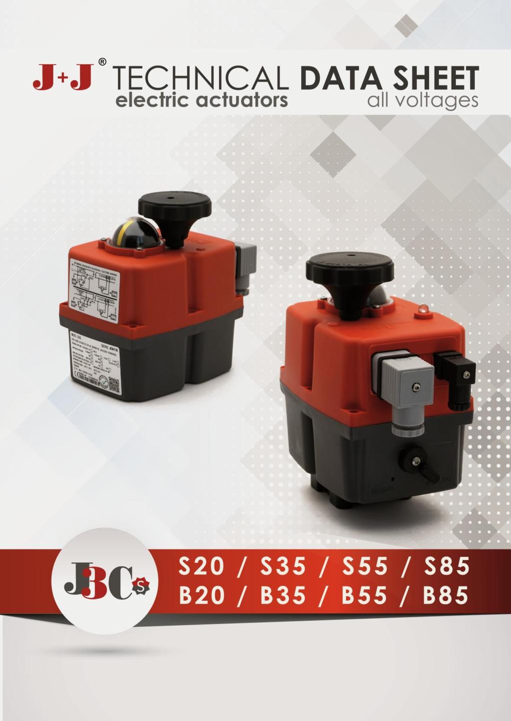
2 ELECTRIC ACTUATOR J3CS S20 & B20 C GENERAL CHARACTERISTICS Housing: Anticorrosive polyamide (lid & body) Main external shaft: Anticorrosive polyamide External screws: stainless steel Gears: Steel and polyamide Visual position indicator: Polyamide Dome: Polycarbonate Adjustable internal cams: Polyamide Electric motor: Single phase 24VDC Insulation: Class B (IEC 60034) Service: S4 DATASHEET Model S20 B20 Voltage VDC/VAC 50/60Hz -0/+5% 24 a 240 (Patent Pending) 12 V ONLY Operation time unload 10 Sec./90º 10 Sec./90º Maximum torque break 25 Nm / 221 lb/in 25 Nm / 221 lb/in Maximum operational torque 20 Nm / 177 lb/in 20 Nm / 177 lb/in Duty rating 75 % 75 % Max. Working angle 0º to 270º 0º to 270º Limit switch 4 SPST NO micro (2 motor stop and 2 confirmations) 4 SPST NO micro (2 motor stop and 2 confirmations) Automatic heater 3,5 W 3,5 W Big Plug EN FORM A EN FORM A Small Plug DIN43650/C DIN43650/C Protection IEC rating IP67 IP67 Temperature -20ºC +70ºC / -4ºF +158ºF -20ºC +70ºC / -4ºF +158ºF Weight 1,8 Kg 1,8 Kg V 0 VALVE CONNECTION ISO 5211 Plate : F03/F04/F05 DIN 3337 Female output drive : *14 mm Options: DIN 3337 Female output drive: *9 or *11 mm F05 to F07 Conversion Kit with *17mm output OPTIONS -J3CS 20/85 DPS 2017 digital positioner: 4-20mA, 0-20mA, 0-10V or 1-10V. -J3CS 20/85 BSR 2017 emergency fail safe kit system by battery -Digital potentiometer: 1K, 5K or 10K. -3 position actuator: 0º-45º-90º or 0º-90º-180º 2
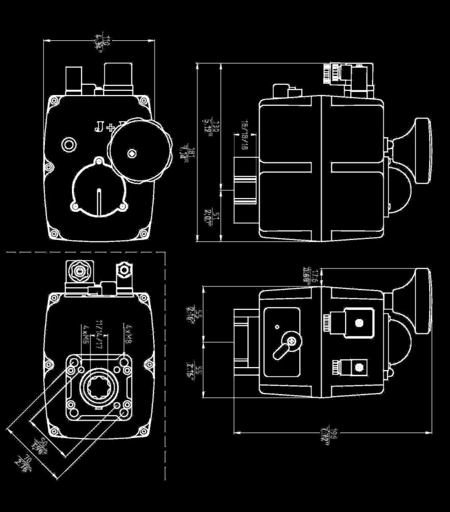
3 J3CS S20 & B20 SIZES 3
4 ELECTRIC ACTUATOR J3CS S35 & B35 C GENERAL CHARACTERISTICS Housing: Anticorrosive polyamide (lid & body) Main external shaft: stainless steel External screws: stainless steel Gears: Steel and polyamide Visual position indicator: Polyamide Dome: Polycarbonate Adjustable internal cams: Polyamide Electric motor: Single phase 24VDC Insulation: Class B (IEC 60034) Service: S4 DATASHEET Model S35 B35 Voltage VDC/VAC 50/60Hz -0/+5% 24 a 240 (Patent Pending) 12 V ONLY Operation time unload 10 Sec./90º 10 Sec./90º Maximum torque break 38 Nm / lb/in 38 Nm / lb/in Maximum operational torque 35 Nm / 309 lb/in 35 Nm / 309 lb/in Duty rating 75 % 75 % Max. Working angle 0º to 270º 0º to 270º Limit switch 4 SPST NO micro (2 motor stop and 2 confirmation) 4 SPST NO micro (2 motor stop and 2 confirmation) Automatic heater 3,5 W 3,5 W Big Plug EN FORM A EN FORM A Small Plug DIN43650/C DIN43650/C Protection IEC rating IP67 IP67 Temperature -20ºC +70ºC / -4ºF +158ºF -20ºC +70ºC / -4ºF +158ºF Weight 1,9 Kg 1,9 Kg V 0 VALVE CONNECTION ISO 5211 Plate : F03/F04/F05 DIN 3337 Female output drive : *14 mm Options: DIN 3337 Female output drive: *9 or *11 mm F05 to F07 Conversion Kit with *17mm output OPTIONS -J3CS 20/85 DPS 2017 digital positioner: 4-20mA, 0-20mA, 0-10V or 1-10V. -J3CS 20/85 BSR 2017 emergency fail safe kit system by battery -Digital potentiometer: 1K, 5K or 10K. -3 position actuator: 0º-45º-90º or 0º-90º-180º 4
5 J3CS S35 & B35 SIZES 5
6 ELECTRIC ACTUATOR J3CS S55 & B55 C GENERAL CHARACTERISTICS Housing: Anticorrosive polyamide (lid & body) Main external shaft: stainless steel External screws: stainless steel Gears: Steel and polyamide Visual position indicator: Polyamide Dome: Polycarbonate Adjustable internal cams: Polyamide Electric motor: Single phase 24VDC Insulation: Class B (IEC 60034) Service: S4 DATASHEET Model S55 B55 Voltage VDC/VAC 50/60Hz -0/+5% 24 a 240 (Patent Pending) 12 V ONLY Operation time unload 14 Sec./90º 14 Sec./90º Maximum torque break 60 Nm / 530 lb/in 60 Nm / 530 lb/in Maximum operational torque 55 Nm / 486 lb/in 55 Nm / 486 lb/in Duty rating 75 % 75 % Max. Working angle 0º to 270º 0º to 270º Limit switch 4 SPST NO micro (2 motor stop and 2 confirmations) 4 SPST NO micro (2 motor stop and 2 confirmations) Automatic heater 3,5 W 3,5 W Big Plug EN FORM A EN FORM A Small Plug DIN43650/C DIN43650/C Protection IEC rating IP67 IP67 Temperature -20ºC +70ºC / -4ºF +158ºF -20ºC +70ºC / -4ºF +158ºF Weight 2,4 Kg 2,4 Kg V VALVE CONNECTION ISO 5211 Plate : F05/F07 DIN 3337 Female output drive : *17 mm Option: DIN 3337 Female output drive: *11 or *14 mm 0 OPTIONS -J3CS 20/85 DPS 2017 digital positioner: 4-20mA, 0-20mA, 0-10V or 1-10V. -J3CS 20/85 BSR 2017 emergency fail safe kit system by battery -Digital potentiometer: 1K, 5K or 10K. -3 position actuator: 0º-45º-90º or 0º-90º-180º 6
7 J3CS S55 & B55 SIZES 7
8 ELECTRIC ACTUATOR J3CS S85& B85 C GENERAL CHARACTERISTICS Housing: Anticorrosive polyamide (lid & body) Main external shaft: stainless steel External screws: stainless steel Gears: Steel and polyamide Visual position indicator: Polyamide Dome: Polycarbonate Adjustable internal cams: Polyamide Electric motor: Single phase 24VDC Insulation: Class B (IEC 60034) Service: S4 DATASHEET Model S85 B85 Voltage VDC/VAC 50/60Hz -0/+5% 24 a 240 (Patent Pending) 12 V ONLY Operation time unload 30 Sec./90º 30 Sec./90º Maximum torque break 90 Nm / 796,3 lb/in 90 Nm / 796,3 lb/in Maximum operational torque 85 Nm / 752 lb/in 85 Nm / 752 lb/in Duty rating 75 % 75 % Max. Working angle 0º to 270º 0º to 270º Limit switch 4 SPST NO micro (2 motor stop and 2 confirmations) 4 SPST NO micro (2 motor stop and 2 confirmations) Automatic heater 3,5 W 3,5 W Big Plug EN FORM A EN FORM A Small Plug DIN43650/C DIN43650/C Protection IEC rating IP67 IP67 Temperature -20ºC +70ºC / -4ºF +158ºF -20ºC +70ºC / -4ºF +158ºF Weight 3 Kg 3 Kg V VALVE CONNECTION ISO 5211 Plate : F05/F07 DIN 3337 Female output drive : *17 mm Option: DIN 3337 Female output drive: *11 or *14 mm 0 OPTIONS -J3CS 20/85 DPS 2017 digital positioner: 4-20mA, 0-20mA, 0-10V or 1-10V. -J3CS 20/85 BSR 2017 emergency fail safe kit system by battery -Digital potentiometer: 1K, 5K or 10K. -3 position actuator: 0º-45º-90º or 0º-90º-180º 8

9 J3CS S85 & B85 SIZES 9

 11 12 13 14 15 16 17 18 19 1-Actuator Model. 2-Voltage to be connected.")
10 J3CS SERIES - MODEL S20, S35, S55, S85, B20, B35, B55 & B85 S & B models - Novelties to be pointed out: 1-VISUAL CONTROL OF OPERATION: Through the VISUAL CONTROL OF OPERATION one could see a different color LED light, fixed or blinking, from which, one could know what is the operation the actuator is making or which is the incidence the actuator is facing. 2- VOLTAGE TO BE CONNECTED VISUAL CONTROL OF OPERATION -All S20 to S85 actuators have been set-up to work from VDC/VAC (Patent pending). -All B20 to B85 actuators have been set-up to work at 12 VDC/VAC ONLY. 3-ID ACTUATOR LABEL (PATENT PENDING) Actuator Model. 2-Voltage to be connected. 3-DPS 2017 options. 4-BSR 2017 options. 5-POTENTIOMETER options. 6-Time the actuator needs to run to the indicated degrees. 7-Actuator ready to bear between 20ºC y + 70ºC. 8-Plate to fix the valve to the actuator, following ISO Female output drive size, following DIN Actuator with the CE certificate. 11-Actuator Series. 12-Working angle. 13-Duty: 75%. Example: S20 Model - Maneuver time = 10sec. Time between maneuvers = 3.3 sec. 14-Actuator with the IP67 protection. 15-Maximum torque break. 16-Bar code of the serial number. 17-Actuator serial number. 18-Quality Control Conformity. 19-QR code for manufacturing. 10
11 4-BSR 2017 J3CS 20/85 KIT For actuator models S20 to S85 and B20 to B85, there is a new BSR 2017 KIT, which drives the actuator to the OPEN (BSR NO) or to the CLOSE position (BSR NC) in case of a power supply failure, by using an internal battery system. Always depending on the previous set-up configuration. 5-DPS 2017 J3CS 20/85 KIT For actuator models S20 to S85 and B20 to B85, there is a new DPS 2017 KIT, which allow us to put the actuator in any position throughout its working angle, by using a 4-20mA or a 0-10V signal. In case one would like to use a 0-20mA or a 1-10V signal, ask the distributor. 11
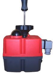
12 ACTUATOR PART LIST MODELS: S20, S35, S55, S85, B20, B35, B55 & B85 MANUAL OVERRIDE POSITION INDICATOR VISUAL CONTROL OF OPERATION VOLT FREE CONTACT PLUG POWER SUPPLY PLUG ISO MULTIFLANGE AUTOMATIC-MANUAL LEVER 12
13 TABLE OF CONSUMPTIONS J3CS 20 Consumption Unload Max. Operational Torque 20Nm Max. Torque Break 25Nm Voltage Model A W A W A W 12 VDC B20 0,75 9,06 1,80 21,60 1,95 23,36 24 VDC S20 0,45 10,77 0,90 21,49 0,97 23,39 48 VDC S20 0,21 9,93 0,42 20,38 0,46 22,07 12 VAC B20 1,04 12,51 1,85 22,18 2,28 27,32 24 VAC S20 0,59 14,20 1,12 26,77 1,28 30,62 48 VAC S20 0,34 16,37 0,69 33,16 0,75 36, VAC S20 0,14 15,73 0,27 29,52 0,30 32, VAC S20 0,10 23,76 0,15 36,43 0,16 39,07 J3CS 35 Consumption Unload Max. Operational Torque 35Nm Max. Torque Break 38Nm Voltage Model A W A W A W 12 VDC B20 0,75 9,06 2,38 28,62 2,62 31,50 24 VDC S20 0,45 10,77 1,28 30,78 1,37 32,79 48 VDC S20 0,21 9,93 0,56 26,72 0,59 28,20 12 VAC B20 1,04 12,51 2,75 33,00 3,19 38,28 24 VAC S20 0,59 14,20 1,58 37,80 1,67 40,13 48 VAC S20 0,34 16,37 0,92 44,04 0,99 47, VAC S20 0,14 15,73 0,36 39,45 0,38 41, VAC S20 0,10 23,76 0,19 45,41 0,20 47,52 J3CS 55 Consumption Unload Max. Operational Torque 55Nm Max. Torque Break 60Nm Voltage Model A W A W A W 12 VDC B20 0,70 8,45 3,04 36,43 3,42 41,05 24 VDC S20 0,42 10,19 1,55 37,17 1,63 39,02 48 VDC S20 0,20 9,72 0,61 29,25 0,67 32,31 12 VAC B20 0,94 11,30 3,43 41,18 3,78 45,41 24 VAC S20 0,58 13,89 1,87 44,88 1,98 47,52 48 VAC S20 0,33 15,73 1,10 52,80 1,21 58, VAC S20 0,14 15,73 0,40 43,80 0,43 46, VAC S20 0,09 22,70 0,20 47,52 0,21 50,16 J3CS 85 Consumption Unload Max. Operational Torque -85Nm Max. Torque Break -90Nm Voltage Model A W A W A W 12 VDC B20 0,62 7,42 2,11 25,34 2,28 27,32 24 VDC S20 0,36 8,55 1,08 25,87 1,22 29,30 48 VDC S20 0,17 8,24 0,48 22,92 0,53 25,56 12 VAC B20 0,81 9,69 2,38 28,51 2,65 31,81 24 VAC S20 0,50 11,88 1,36 32,74 1,50 36,01 48 VAC S20 0,25 11,83 0,77 37,07 0,86 41, VAC S20 0,12 12,83 0,31 33,64 0,33 36, VAC S20 0,08 20,06 0,17 40,13 0,18 42,77 13
 PIN 1 = (-) Negative + PIN 2 = (+) Positive = Close PIN 1 = (-) Negative + PIN 3 = (+) Positive = Open B = Volt free contact, plug PIN 1 / PIN 2 = Close PIN 1 / PIN 3 = Open A B 2 WIRES ON -")
 PIN 1 = Neutral + PIN 2 = Phase = Power supply plug A: VDC 2 WIRES (Grey plug) PIN1=(-) Negative + PIN 2=(+)")
14 EXTERNAL CONNECTING DIAGRAM 3 WIRES ON - OFF A B A = Power supply plug A: VAC 3 WIRES (Grey plug) PIN 1 = Neutral + PIN 2 = Phase = Close PIN 1 = Neutral + PIN 3 = Phase = Open A: VDC 3 WIRES (Grey plug) PIN 1 = (-) Negative + PIN 2 = (+) Positive = Close PIN 1 = (-) Negative + PIN 3 = (+) Positive = Open B = Volt free contact, plug PIN 1 / PIN 2 = Close PIN 1 / PIN 3 = Open A B 2 WIRES ON - OFF A = Power supply plug A: VDC 2 WIRES (Grey plug) PIN 2 = (+) Positive + PIN 3 = (-) Negative = Close PIN 2 = (-) Negative + PIN 3 = (+) Positive = Open B = Volt free contact plug PIN 1 / PIN 2 = Close PIN 1 / PIN 3 = Open POSITIONER A = Power supply plug A: VAC 2 WIRES (Grey plug) PIN 1 = Neutral + PIN 2 = Phase = Power supply plug A: VDC 2 WIRES (Grey plug) PIN1=(-) Negative + PIN 2=(+) Positive = Power supply plug A B C Instrumentation Signal NO VOLTAGE B = Instrumentation Signal B: Input signal : 4/20mA or 0/10V PIN 1 = (-) Negative + PIN 2 = (+) Positive = Input signal PIN 1 = (-) Negative + PIN 3 = (+) Positive = Output signal C = Volt free contact plug PIN 1 / PIN 2 = Closed PIN 1 / PIN 3 = Open 14
15 ACTUATOR OPERATIONAL STATUS MODELS: S20, S35, S55, S85, B20, B35, B55 & B85 The LED Light provides visual communication between the actuator and the user. The current operational status is shown by different LED colors. VISUAL CONTROL OF OPERATION ON-OFF ACTUATOR ACTUATOR OPERATIONAL STATUS Without power supply In open position In close position Opening Closing Torque limiter function on, moving from close to open Torque limiter function on, moving from open to close Actuator in MANUAL mode (Exceeded time) The actuator has stopped (no close/no open position) In middle position ACTUATOR WITH BSR 2017 ACTUATOR OPERATIONAL STATUS Without power supply In open position In close position Opening Closing Torque limiter function on, moving from close to open Torque limiter function on, moving from open to close Actuator in MANUAL mode (Exceeded time) The actuator has stopped (no close/no open position) In middle position Actuator without power, working with the BSR NO system. Max.3 min., (led off) Actuator without power, working with the BSR NC system. Max.3 min., (led off) Battery protection. Danger, the battery needs recharging. BSR blocked 15
16 ACTUATOR WITH DPS 2017 Without power supplied ACTUATOR OPERATIONAL STATUS Motor stop Opening Closing Self adjusting configuration Torque limiter function on, moving from close to open Torque limiter function on, moving from open to close Instrum. Signal overpassed. Blocked actuator. Need a re-set. Actuator in MANUAL mode (exceeded time) No Instrum. Signal pick-up. 4-20mA and 1-10V only. 16


17 DPS 2017 J3CS 20/85 ESPECIFICACIONES / SPECIFICATIONS MODELO / MODEL S20-B20 S35-B35 S55-B55 S85-B85 Precisión Accuracy Linealidad Linearity Histéresis Hysteresis Impulsos a 4/20mA Steps at 4/20mA Impulsos a 0/10V Steps at 0/10V Impulsos a 0/20mA Steps at 0/20mA Impulsos 1/10V Steps at 1/10V Impedancia señal entrada 4/20mA o 0/20mA 4/20mA or 0/20mA Input signal impedance Impedancia señal entrada 0/10V o 1/10V 0/10V or 1/10V Input signal impedance CLASE / CLASS 3 % F.S. 3 % F.S. 3 % F.S. 3 % F.S. 2 % F.S. 2 % F.S. 2 % F.S. 2 % F.S. 3 % F.S. 3 % F.S. 3 % F.S. 3 % F.S. Min.142 steps 90º Min.142 steps 90º Min.142 steps 90º Min.142 steps 90º Min.88 steps 90º Min.88 steps 90º Min.88 steps 90º Min.88 steps 90º Min.166 steps 90º Min.166 steps 90º Min.166 steps 90º Min.166 steps 90º Min.85 steps 90º Min.85 steps 90º Min.85 steps 90º Min.85 steps 90º 100 Ohm 100 Ohm 100 Ohm 100 Ohm 25 KOhm 25 KOhm 25 KOhm 25 KOhm B+C to E DIN EN Inching + Modulation PESO / WEIGHT 0,600 Kg 0,600 Kg 0,600 Kg 0,600 Kg F.S. Se refiere a todo el rango de medición F.S. Full Scale 17


18 DPS 2017 J3CS 20/85 Aplicar la configuración necesaria para cada aplicación: Posibles configuraciones: Use the configuration you need by moving the DIPs: Different possibilities of configuration: 4/20 ma NC 0/10 V NC 1/10 V NC 4/20mA NO 0/10 V NO 1/10 V NO OTRAS OPCIONES A CONFIGURAR EN FABRICA O CON INTERFACE J3CS OTHER OPTIONS TO BE SET-UP BY THE MANUFACTURER OR WITH A J3CS INTERFACE SOLO SALIDA / OUTPUT ONLY ENTRADA Y SALIDA / INPUT & OUTPUT PARO MOTOR, A FALTA DE INSTRUMENTACIÓN / MOTOR STOP, WITHOUT INSTUMENTATION 4/20 ma, 0/10 V, 0/20 ma, 1/10 V 0/20 ma 4/20 ma, 0/10 V, 0/20 ma, 1/10 V 18


 NO or NC Features (*) 5 5 5 5 15 min 21 min 48 min 58 min")

19 BSR 2017 J3CS 20/85 J3CS-20 J3CS-35 J3CS-55 J3CS-85 ESPECIFICACIONES / SPECIFICATIONS MODELO ACTUADOR / ACTUATOR MODEL S20-B20 S35-B35 S55-B55 S85-B85 Nº de Maniobras sin recargar, con batería 100% de carga Nº Working operation without recharge, with 100% battery charge Tiempo de recarga/ maniobra. Recharge time/working operation Consumo de batería/maniobra. Battery consumption/working operation Tiempo de carga completa 100% Full charge time 100% Capacidad nominal +/- 5% Nominal capacity +/- 5% Configuración NA o NC (*) NO or NC Features (*) min 21 min 48 min 58 min 2,2 W 3,0 W 6,8 W 8,3 W 28 h 28 h 28 h 28 h 1000 ma 1000 ma 1000 ma 1000 ma Jumper Jumper Jumper Jumper Consumo/una maniobra con batería Current/one working operation with battery 10,1 ma 14 ma 31,6 ma 38.6 ma Carga batería Battery charge 40 ma/h 40 ma/h 40 ma/h 40 ma/h Peso Weight 0,27 Kg 0,27 Kg 0,27 Kg 0,27 Kg 19
 NORMALMENTE CERRADA (NC) NORMALLY CLOSE (NO) NORMALMENTE ABIERTA (NO) NORMALLY OPEN (*) Configuración NA o NC / NO")


20 CONFIGURACIONES / CONFIGURATIONS A B POSICION PREFERENTE A FALLO DE CORRIENTE PREFERRED POSITION IN CASE OF POWER CUT (NC) NORMALMENTE CERRADA (NC) NORMALLY CLOSE (NO) NORMALMENTE ABIERTA (NO) NORMALLY OPEN (*) Configuración NA o NC / NO or NC Set-Up Configuración NC / NC Set-Up NC - Si deseamos que el actuador, a fallo de corriente CIERRE, es necesario insertar el jumper 1 en la posición SELDIR. NC - If, in case of a power supply failure, we need the actuator go to the CLOSE position, we need to put the jumper 1 on the SELDIR position. Configuración NA / NO Set-Up NO - Si deseamos que el actuador, a fallo de corriente ABRA, comprobar que en la posición SELDIR, no tenga el jumper 1 montado. NO - If, in case of a power supply failure, we need the actuator go to the OPEN position, be sure that the jumper 1 is not on the SELDIR position. Jumper 1 SELDIR OPCIONES CONEXIONES EXTERNAS / EXTERNAL ELECTRIC WIRING OPTIONS (3 CABLES) / (3 WIRES) (2 CABLES) / (2 WIRES) 20
21 KIT DPS 2017 J3CS 20/85 OUTSIDE BOX INSIDE BOX El DPS 2017 es un accesorio para los actuadores eléctricos J3CS que los convierte en posicionador de válvulas servo controladas. El DPS 2017 es un módulo que incorpora un microprocesador (CPU) el cual controla digitalmente la entrada y salida de señal analógica y compara ambas con la posición del actuador a fin de establecer una relación uniforme. Las entradas analógicas son enviadas a la CPU donde son procesadas en continua comparación con la posición del actuador lo cual permite obtener un muy alto grado de sensibilidad y una muy alta repetitividad de posición (ver características). El posicionador DPS 2017, en comunicación con el sistema electrónico del actuador, provee un control integral del movimiento del actuador. The DPS 2017 is a device for the J3CS electric actuator that turns the actuator into a servo controlled valve positioner. The DPS 2017 is a modulus with a microprocessor (CPU) which digitally manages the analogical input and output and compare them with the position of the actuator to establish a uniform relation. The analogical inputs are sent to the CPU where they are processed for his continuous comparison with the position of the actuator, this allows to obtain a very high sensitivity next to a very high repetitivity of the position (see characteristics). The DPS 2017 in communication with the electronic system of the actuator provides an integral management of the motion of the actuator. 21


22 KIT DPS 2017 J3CS 20/85 OUTSIDE BOX INSIDE BOX ESPECIFICACIONES / SPECIFICATIONS MODELO / MODEL S20-B20 S35-B35 S55-B55 S85-B85 Precisión Accuracy Linealidad Linearity Histéresis Hysteresis Impulsos a 4/20mA Steps at 4/20mA Impulsos a 0/10V Steps at 0/10V Impulsos a 0/20mA Steps at 0/20mA Impulsos 1/10V Steps at 1/10V Impedancia señal entrada 4/20mA o 0/20mA 4/20mA or 0/20mA Input signal impedance Impedancia señal entrada 0/10V o 1/10V 0/10V or 1/10V Input signal impedance CLASE / CLASS 3 % F.S. 3 % F.S. 3 % F.S. 3 % F.S. 2 % F.S. 2 % F.S. 2 % F.S. 2 % F.S. 3 % F.S. 3 % F.S. 3 % F.S. 3 % F.S. Min.142 steps 90º Min.142 steps 90º Min.142 steps 90º Min.142 steps 90º Min.88 steps 90º Min.88 steps 90º Min.88 steps 90º Min.88 steps 90º Min.166 steps 90º Min.166 steps 90º Min.166 steps 90º Min.166 steps 90º Min.85 steps 90º Min.85 steps 90º Min.85 steps 90º Min.85 steps 90º 100 Ohm 100 Ohm 100 Ohm 100 Ohm 25 KOhm 25 KOhm 25 KOhm 25 KOhm B+C to E DIN EN Inching + Modulation PESO / WEIGHT 0,600 Kg 0,600 Kg 0,600 Kg 0,600 Kg F.S. Se refiere a todo el rango de medición F.S. Full Scale 22

.")
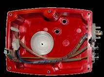
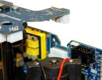
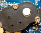
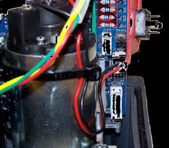
23 KIT DPS 2017 J3CS 20/85 ASSEMBLY INSTRUCTIONS V001 PIECES 1-1 Cover pin grey power DIN plug pin small black DIN plug 4-1 Rubber join for the big grey DIN plug 5-2 Rubber join for the small black DIN plug 6-1 Fixing screw for the grey DIN plug 7-1 Fixing screw for the black DIN plug 8-1 Hexagonal column 9-1 DPS 2017 positioner PCB 10-1 Plastic clamp 11-1 DIN 7985 M4X8 screw 12-2 O-ring 13-1 Cover cap 14-1 Plastic clip PLEASE READ CAREFULLY BEFORE MOUNTING. VERY IMPORTANT!!!! PLEASE FOLLOW THE INSTRUCTIONS STEP BY STEP. BEFORE CONNECTING A PLUG TO THE ACTUA- TOR, CHECK THAT THE VOLTAGE IS THE SAME AS THE ONE SPECIFIED ON THE LABEL (CARTER). PREPARING THE COVER: J3CS-20, 35 & 55 model: Insert the o-ring (12) and the cover cap (13) inside hole nº1. Press until they are fully inside (Fig.1). Insert the o-ring (12) and the Plastic clip (14) inside hole nº2. Press until they are fully inside (Fig.2). J3CS-85 model: Insert the o-ring (12) and the cover cap (13) inside hole nº2. Press until they are fully inside (Fig.1). Insert the o-ring (12) and the Plastic clip (14) inside hole nº1. Press until they are fully inside (Fig.2). TO CONVERT A STANDARD (ON-OFF) J3CS ELECTRIC ACTUATOR INTO A MODULATING FUNCTION WITH POSITIONER, PROCEED AS FOLLOWS: The unit must be disconnected from any electrical power or signal before installing. 1. Remove the screw from the cover of the hand wheel and take the cover off (Fig.3). 2. Do the same with the screw which is fixing the hand wheel. Take the hand wheel off. (Fig.4). 3. Remove the 6 screws, which are fixing the body to the cover of the actuator (Fig.5). 4. Carefully lift the cover and remove the cables connected to the actuator PCB (Fig.6). 5. Carefully remove the position indicator (Fig.7). 6. Remove the screw from the base plate (Fig.8). 7. Fix the hexagonal column (8) on the base plate (Fig.9). 8. Take the DPS 2017 cover and connect the 3 pin power supply plug to its connector base (1) on the actuator PCB (Fig.10). Connect the 5 pin confirmation plug into its connector base on the actuator PCB (2) (Fig.10). Then connect the earth connector (yellow/green) cable into its connector base (3) (Fig.10). 9. Mount the DPS2017 positioner PCB (9), matching the cleft of the shaft with the key inside the DPS 2017 gear (Fig.11). Be sure that the Power Supply cable remains as per in the picture (Fig. 12). Press the DPS2017 positioner PCB (9) along the shaft until the PCB connector (JP3) is plugged in the actuator PCB connector (JP2) (Fig.13). 10.Fix the DPS2017 positioner PCB (9) to the hexagonal column (8) with the screw (11) (Fig.14). 11.Connect the 4 pin control signal plug (DPS 2017 cover) into the corresponding connector base (4) on the DPS 2017 PCB (Fig.15). 12. Fix the (blue, black and brown) cables by a plastic clamp (10) to the hexagonal column (8) (Fig.16). Cut down the remaining piece of clamp. 13. Carefully insert the position indicator, matching its inner key with the cleft of the shaft (Fig.17). 14. In order to set the actuator up, use the DIPs shown in picture (Fig.18). Put DIP 1 in ON position, connect the grey connector to the power supply, put DIP 1 back to the prior position. Wait until the actuator make a complete maneuver. 15.Use the configuration you need by moving the DIPs: 4/20 ma NC 0/10 V NC 1/10 V NC 4/20mA NO 0/10 V NO 1/10 V NO 16. Disconnect the grey connector from the power supply. 17. Carefully mount the cover, minding the cables not to be pressed (Fig.19). 18. Fix the cover to the body by using the 6 screws (Fig.20). 19.Mount the hand wheel on the shaft and fix it by using the screw (Fig.21). 20. Put the cover on the hand wheel and fix it by using the screw (Fig. 22). 21. Mount the 3 connectors (2&3) together with its rubber joints (4&5) and fix them to the cover, by using the screws (6&7) (Fig.23). The unit is ready to work. Outer Set-Up: Only if necessary. - B plug - Connect a cable between PIN 1 and PIN Earth (Fig. 24). - A plug - Connect it to the power supply. - B plug, disconnect the cable between PIN 1 and PIN Earth. The actuator will make a complete maneuver. Connect B connector to the actuator. The actuator is ready to work. 23


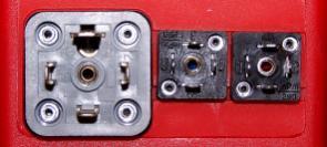
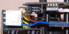
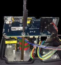
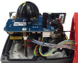
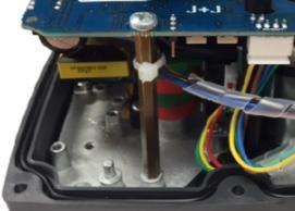
24 Hole nº1 Hole nº2 PREPARING THE COVER Fig.3 Fig. 4 Fig.5 Fig.1 Fig.2 Fig.6 Fig.7 Fig.8 Fig Fig.10 Fig.11 Fig.12 3 cleft key Fig.13 Fig.14 4 Fig.15 Fig.16 JP3 JP2 Fig.17 Fig.18 Fig.19 Fig.20 Fig.21 Fig.22 Fig.23 PIN 1 Fig.24 A B C 24
. C- Conector señales confirmación (libres de tensión).")
25 DPS 2017 J3CS 20/85 Autoajuste externo DPS 2017/ DPS 2017 External Self-adjustment A B C A- Conector alimentación corriente (Voltaje). B- Conector alimentación instrumentación (4/20mA,0/10V,0/20mA o 1/10V). C- Conector señales confirmación (libres de tensión). 1-En el conector B, hacer un cruce entre el PIN1 (PIN izquierda) y el PIN TIERRA (PIN inferior). 2-En el conector A, conectar el voltaje al actuador de la siguiente manera. VAC: PIN1 (neutro) y PIN2 (fase). VDC: PIN1 (negativo) y PIN2 (positivo). *IMPORTANTE: ANTES DE CONECTAR EL CONECTOR A AL ACTUADOR, REVISAR QUE EL VOLTAJE COINCIDA CON EL DE LA ETIQUETA PEGADA AL ACTUADOR (PARTE COLOR GRIS). 3-En el conector B, deshacer el cruce entre el PIN1 (PIN izquierda) y el PIN TIERRA (PIN inferior). El actuador realizara una maniobra completa y se quedara en la posición de cerrado. El actuador ya está listo para conectar la señal de instrumentación en el conector B. A- Power supply plug. B- Input / Output signal (4/20mA,0/10V,0/20mA o 1/10V) plug. C- Volt free contact plug. 1-B plug - connect a cable between PIN 1 (on the left side) and PIN Earth (on the bottom). 2-A plug - connect: VAC: PIN1 (neutral) and PIN2 (phase). VDC: PIN1 (negative) and PIN2 (positive). *VERY IMPORTANT: BEFORE CONNECTING A PLUG TO THE ACTUATOR, CHECK THAT THE VOLTAGE IS THE SAME AS THE ONE SPECIFIED ON THE LABEL (CARTER). 3-B plug - disconnect the cable between PIN 1 (on the left side) and PIN Earth (on the bottom). The actuator will make a complete maneuver and stay in the close position. The actuator is ready to connect the (4/20mA,0/10V,0/20mA o 1/10V) signal to the B plug. 25
26 KIT BSR 2017 J3CS 20/85 OUTSIDE BOX INSIDE BOX El sistema de seguridad BSR 2017 es un automatismo que, incorporado a los actuadores J3CS permite, en caso de interrupción de la alimentación eléctrica, situar la válvula en posición preferente predeterminada NC o NA. En el interior del actuador se encuentra situada la tarjeta del circuito BSR 2017 más el bloque de baterías que, se encuentra en carga continua, lo que permite accionar el actuador, en caso necesario, cuando la unidad detecta un fallo de suministro eléctrico. Hay que tener en cuenta que no se trata de un actuador simple efecto, pero que en caso de que la válvula se encuentre en posición no preferente, el sistema BSR 2017, mediante las baterías, accionará la válvula hasta situarla en la posición predeterminada como preferente, actuando como un actuador simple efecto. The BSR 2017 safety block system is an automatism that, when coupled to the J3CS multi voltage electric actuators, lets the valve situate in a preferable position NC or NO, when there is a power supply failure. Inside of the housing there are a BSR 2017 print circuit board and a battery pack, which is kept in continuous charge. In case of the valve is not in the preferable position and there is a power supply cut, the BSR 2017 system returns the valve back to the preferable position by means of the batteries tension, operating as a single acting actuator. 26


27 KIT BSR 2017 J3CS 20/85 OUTSIDE BOX INSIDE BOX ESPECIFICACIONES / SPECIFICATIONS MODELO ACTUADOR / ACTUATOR MODEL S20-B20 S35-B35 S55-B55 S85-B85 Nº de Maniobras sin recargar, con batería 100% de carga Nº Working operation without recharge, with 100% battery charge Tiempo de recarga/ maniobra. Recharge time/working operation Consumo de batería/maniobra. Battery consumption/working operation Tiempo de carga completa 100% Full charge time 100% Capacidad nominal +/- 5% Nominal capacity +/- 5% Configuración NA o NC (*) NO or NC Features (*) min 21 min 48 min 58 min 2,2 W 3,0 W 6,8 W 8,3 W 28 h 28 h 28 h 28 h 1000 ma 1000 ma 1000 ma 1000 ma Jumper Jumper Jumper Jumper Consumo/una maniobra con batería Current/one working operation with battery 10,1 ma 14 ma 31,6 ma 38.6 ma Carga batería Battery charge 40 ma/h 40 ma/h 40 ma/h 40 ma/h Peso Weight 0,27 Kg 0,27 Kg 0,27 Kg 0,27 Kg 27


. 4. Carefully remove the cover, in order to install the kit. (Fig.4). 5. Remove the screw indicated in (Fig.5). 6. Place the battery pack (C) on the indicated position (Fig.")
 from the KIT and connect it to the actuator PCB, by using the connectors marked with a circle. See (Fig.8). 9. Fix the BSR PCB to the base plate by using the screw (B). See (Fig.9).")
 jumper OFF. 12. Carefully replace the cover and be sure that the joint is correctly lodged in its place. See (Fig.12).")
28 J3CS 20/85 KIT BSR 2017 ASSEMBLY INSTRUCTIONS VERY IMPORTANT: PLEASE, FOLLOW THESE INSTRUCTIONS STEP BY STEP.IF THE CONNECTOR OF THE BATTERY PACK IS PLUGED TO THE BSR PCB, BEFORE ARRIVING TO POINT 9, THE PCB COULD BE DAMAGED. KIT COMPONENT A B DOCUMENT TO FILL IN A 1 BSR PCB B 1 BSR PCB Fixing screw C 1 Battery C D D 1 Plastic washer E 1 Battery Fixing screw ASSEMBLY INSTRUCTIONS INNER BOX F 1 Washer E F BSR PCB set-up: Please see the attached label: Option 1: If BSR 2015, is on the label, remove the jumper and follow point 1. Optionn 2: If BSR 2017 is on the label, check the jumper is connected and follow point 1. remove jumper connected jumper 1. Remove the cover of the hand wheel. 2. Remove the hand wheel screws and take the hand wheel off. (Fig. 1 & 2). 3. Remove the 6 screws between the cover and the body of the actuator.(fig.3). 4. Carefully remove the cover, in order to install the kit. (Fig.4). 5. Remove the screw indicated in (Fig.5). 6. Place the battery pack (C) on the indicated position (Fig.6). 7. Take the screw kit (E), put the plastic washer (D), put the washer (F) along the screw and introduce it in the battery (Fig.7). Fix the battery to the base plate. 8. Take the BSR PCB (A) from the KIT and connect it to the actuator PCB, by using the connectors marked with a circle. See (Fig.8). 9. Fix the BSR PCB to the base plate by using the screw (B). See (Fig.9). 10. Plug the battery pack connector to the BSR PCB base connector, located on the top of this PC(Fig.10). 11. BSR Configuration (Fig.11 jumper SELDIR): NC (normally close) jumper ON. NO (normally open) jumper OFF. 12. Carefully replace the cover and be sure that the joint is correctly lodged in its place. See (Fig.12). Be sure that any cable is not trapped between the cover and the body. 13. Fix the 6 screws, between the cover and the body. See (Fig.13). 14. Reassemble the hand wheel and fix it with the screws. See (Fig.14). 15. Put the hand wheel cover back and fix it with the screw. See (Fig.15). 16. Fill in the blanks of the document inside the BSR KIT and send it back to the supplier, via fax or mail. Now, the actuator is ready to work. We strongly recommend to put the power on, send the actuator to an intermediate position and check that, after putting the power off, the actuator goes to the pervious set-up position (NC or NO). 28


29 Fig.1 Fig.2 Fig.3 Fig.4 Fig.5 Fig.6 Fig.7 Fig.8 Fig.9 Fig.10 Fig.11 Jumper SELDIR Fig.12 Fig.13 Fig.15 Fig.14 29
ELECTRIC ACTUATOR J3CS S20 & B20 DATASHEET
 4400xxB ELECTRIC ACTUATOR J3CS S20 & B20 C GENERAL CHARACTERISTICS Housing: Anticorrosive polyamide (lid & body) Main external shaft: Anticorrosive polyamide External screws: stainless steel Gears: Steel
ELECTRIC ACTUATOR S20 - S35 - S55 - S85
 ELECTRIC ACTUATOR S20 - S35 - S55 - S85 ELECTRIC ACTUATOR J3C S20 C GENERAL CHARACTERISTICS Housing: Anticorrosive polyamide (lid & body) Main external shaft: Anticorrosive polyamide External screws: stainless
ECP3, ECP5, ECP8 Series Actuators
 INSTALLATION, OPERATION AND MAINTENANCE INSTRUCTIONS ECP3, ECP5, ECP8 Series Actuators TO PREVENT POTENTIAL INJURY OR DAMAGE TO PROPERTY, READ THIS MANUAL CAREFULLY AND COMPLETELY. Page 1 of 24 IMPORTANT
Available with actuator function: POWER OPEN - POWER CLOSE FAILSAFE MODULATING FAILSAFE MODULATING. Overview. 11 or 14mm drive output (Option)
") Feature rich J+J multi-voltage smart electric actuator with LED status light and function conversion kits. J3C-S85 Overview The J3C-S85 multi-voltage electric valve actuator from the electric actuator
Feature rich J+J multi-voltage smart electric actuator with LED status light and function conversion kits. J3C-S85 Overview The J3C-S85 multi-voltage electric valve actuator from the electric actuator
Electric Actuator J3C ELECTRIC ACTUATOR. Actuators
 Specialist in Ball Valves J3C ELECTRIC ACTUATOR Technical data Housing: Body and cover: anticorrosive polyamide Main external shaft: stainless steel Fastening: stainless steel Gears: steel and polyamide
Electric Actuated Ball Valves 2-way Stainless Steel, Full Port 1/4 to 2 inch NPT
 Electric Actuated Ball Valves 2-way Stainless Steel, Full Port 1/4 to 2 inch NPT SERIES Features Full Port 16 Stainless Steel ball valve LED light gives continuous status indication IP67 weatherproof polyamide
Electric Actuated Ball Valves 2-way Stainless Steel, Full Port 1/4 to 2 inch NPT
 Electric Actuated Ball Valves 2-way Stainless Steel, Full Port 1/4 to 2 inch NPT SERIES Features Full Port 16 Stainless Steel ball valve LED light gives continuous status indication IP67 weatherproof polyamide
Electric Actuated Ball Valves 3-Piece Stainless Steel, Full Port 1/4 to 3 inch NPT
 Electric Actuated Ball Valves 3-Piece Stainless Steel, Full Port 1/4 to 3 inch NPT SERIES Features Direct mount Full Port 316 Stainless Steel ball valve 3-piece swing out body designed for easy maintenance
Electric Actuated Ball Valves 150 lb Flanged Stainless Steel, Full Port 1/2 to 4 inch Pipe Sizes
 Electric Actuated Ball Valves 150 lb Flanged Stainless Steel, Full Port 1/2 to 4 inch Pipe Sizes SERIES Features Direct mount Full Port 16 Stainless Steel ball valve 2-piece ANSI Class 150 flanged body
SENSORES DE PAR DINÁMICO SERIE 2100
 SENSORES DE PAR DINÁMICO SERIE 2100 Rango de medida desde 2,5 hasta 500 Nm bidireccional Repetitividad
E J3-Series. Electric quarterturn / partturn actuators. ASC Armaturen GmbH - D Popelau
 E J-Series Electric quarterturn / partturn actuators ASC Armaturen GmbH - D 97 Popelau phone.: +49/884/68-0 Fax: +49/884/68- e-mail: info@ascarmaturen.de www.ascarmaturen.de ISO-Interface Optical function
Clase de precisión División mínima Carga límite Nominal capacity Ln. Breaking load > 350 % Ln
 MODELO 740D 15... 60t DIGITAL Célula de carga digital de compresión de columna pivotante autocentrante divisiones OIML R60 clase C Construcción en acero inoxidable Herméticamente soldada, protección IP
J3C-L Nm Smart Electric Valve Actuator Failsafe Function Type: J3C Model: L140-BSR
 Failsafe Function Type: JC Model: L140-BSR Feature rich J+J multi-voltage smart electric actuator with LED status light and function conversion kits. Overview The JC-L140 low voltage electric valve actuator
J3C-H Nm Smart Electric Valve Actuator
 JC-H140 170Nm Smart Electric Valve Actuator Type: JC Model: H140 Feature rich J+J multi-voltage smart electric actuator with LED status light and function conversion kits. Overview The JC-H140 high voltage
J3C-H20 25Nm Smart Electric Valve Actuator
 JC-H20 25Nm Smart Electric Valve Actuator Type: JC Model: H20 Available with actuator function: POWER OPEN - POWER CLOSE FAILSAFE MODULATING FAILSAFE MODULATING Feature rich J+J multi-voltage smart electric
Model 20 DPS.2005 Doc: J2-20DPS2005/01 Nov 2006
 Model 20 DPS.2005 Doc: J2-20DPS2005/01 J2-20 IP65 Modulating Electric Actuator Main Features: The maintenance free J2 electric actuator is very user friendly. It offers more standard features than any
Electric Actuated 3-Way Ball Valves T-Port, Stainless Steel, Full Port 1/4 to 2 inch NPT
 Electric Actuated 3-Way Ball Valves T-Port, Stainless Steel, Full Port 1/4 to 2 inch NPT SERIES Features Full Port 316SS diverter valve Polyamide IP67 weatherproof enclosure with UV protection Multi-voltage
Electric Actuated Butterfly Valves Ductile Iron Wafer Body ANSI/ASME 150 lb 2 to 6 inch Pipe
 Electric Actuated Butterfly Valves Ductile Iron Wafer Body ANSI/ASME 150 lb 2 to 6 inch Pipe SERIES Features Wafer butterfly valve with ISO5211 direct mount actuator Unique wave line seat reduces torque
MECÁNICA PRISMA, S.L. Actuadores Neumáticos Rotativos -INOX AISI-316- Rotary Pneumatic Actuators -AISI-316 S.S.-
 MECÁNICA PRISMA, S.L. Actuadores Neumáticos Rotativos -INOX AISI-6- Rotary Pneumatic Actuators -AISI-6 S.S.- ACTUADORES NEUMATICOS DE ACERO INOXIDABLE -INDICE- PNEUMATIC ACTUATORS IN STAINLESS STEEL -INDEX-
Clavijas y tomas industriales Industrial plugs & sockets
 CAJAS Y TOMAS DE CORRIENTES INDUSTRIALES INDUSTRIAL ENCLOSURES AND INDUSTRIAL PLUGS/SOCKETS Clavijas y tomas industriales Industrial plugs & sockets PROTECCIÓN IP44/67 / IP44/67 PROTECTION 68 Las clavijas
Datasheet LEDFLOODSTRIP PLUS. 14/03/18 Grupo MCI
 Datasheet LEDFLOODSTRIP PLUS 14/03/18 Grupo MCI 230V / 24V 24V and 230V (monocolor 110 ) types 5 beam angles: 15, 34, 47, 42x25 and 110 4 Light colors: 2700K, 3000K, 4000K and 6000K, RGB and RGBW types
ELECTRIC ACTUATOR MOD. VB015 MAINTENANCE AND INSTALLATION INSTRUCTIONS OF VALBIA ELECTRIC ACTUATORS
 ELECTRIC ACTUATOR MOD. VB015 MAINTENANCE AND INSTALLATION INSTRUCTIONS OF VALBIA ELECTRIC ACTUATORS TABLE OF CONTENTS 1.0 - WARNINGS 2.0 - GENERAL DATA 2.1 - Technical characteristics 2.2 - Data on electrical
HQ008-HQ0120 Electric Actuator
 SKU: AP9002 HQ008-120 Electric Actuator Electric Actuator Elektrischer Antrieb actuador eléctrico Series HQ008-HQ120 Electric Actuator Description The HQ series HQ008 HQ120 are rotary quarter turn electric
Electric Actuated 3-Way Ball Valves L-Port, PVC Body, Teflon/EPDM Seals 1/2 to 2 inch Pipe
 Electric Actuated 3-Way Ball Valves L-Port, PVC Body, Teflon/EPDM Seals 1/2 to 2 inch Pipe SERIES Features Industrial grade PVC ball valve with PTFE/EPDM seals IP67 weatherproof polyamide enclosure with
DRIESCHER Y WITTJOHANN, S.A. MEDIUM VOLTAGE SOLUTIONS
 DRIESCHER Y WITTJOHANN, S.A. MEDIUM VOLTAGE SOLUTIONS TECHNICAL SPECIFICATION LOAD BREAK DISCONNECTOR SWITCHES WITHOUT FUSE HOLDER UIT FUSE HOLDER SECTION CONTENTS PAGE 1 General Features 3 2 Standards
Electric FIP Type TKD ABS 3 Way Ball Valve
 Electric actuator fitted via EasyFit-F kit Sizes: DN15-50 D20-6 1/2-2 Main JCS Smart electric actuator features: LED light for continual visual actuator status feedback. Fully weatherproof smart industrial
Technical Instructions Flowrite 599 Series SKD6xU Electronic Valve Actuators 24 Vac Proportional Control Description Features Application
 Document No. 155-180P25 Flowrite 599 Series SKD6xU Electronic Valve Actuators 24 Vac Proportional Control Description The Flowrite 599 Series SKD6xU Electronic Valve Actuators require a 24 Vac supply and
SLIM GROUND LINER 198 GRUPO MCI
 Continuous light for paths and squares Homogenous light without visible dots Linear rigid body Protection class IP67 Dimmable Small dimensions Easy serial connection BIN control Luz continua para calles
Power Inverters, DC/DC Converters & Supplies Inversores, Reductores & Fuentes de Alimentación
 Giving Shape to your Accessories Power Inverters, DC/DC Converters & Supplies Inversores, Reductores & Fuentes de Alimentación www.komunicapower.com 2 2 Switching Power Supply Fuente de Alimentación AV-825-BCM
AP9002. HQ004 and HQ006 Electric Actuator
 HQ004 and HQ006 Electric Actuator Output torques of 40 and 60Nm respectively Reversible motor with low current consumption IP67 weatherproof Two M20 cable entries Manual override Anti-condensation heater
Flowrite EA 599 Series SKB/C/D 62UA Series Electronic Valve Actuator 24 Vac Proportional Control Advanced Features
 Flowrite EA 599 Series SKB/C/D 62UA Series Electronic Valve Actuator 24 Vac Proportional Control Advanced Features Technical Instructions Document No. 155-717 EA-599-18 SKB/C SKD Description The Flowrite
Flowrite EA 599 Series SKB/C/D 62UA Series Electronic Valve Actuator 24 Vac Proportional Control Advanced Features
 Flowrite EA 599 Series SKB/C/D 62UA Series Electronic Valve Actuator 24 Vac Proportional Control Advanced Features Technical Instructions Document No. 55-77 EA-599-8 April 3, 24 EA228R EA379R SKB/C SKD
Series HQ008- HQ120 Electric Actuator
 SKU: AP9016 HQ008-120 Electric Actuator Electric Actuator Elektrischer Antrieb actuador eléctrico actionneur électrique Series HQ008- HQ120 Electric Actuator Description The HQ series HQ008 HQ120 are rotary
Electric Actuators Maximum in-lbs
 Maximum 14040 in-lbs NEMA 4, 4X, 7 ER- Series Features ISO / DIN valve interface Mounting in any position Thermal overload protection (AC & DC except 12 VDC) Friction brake (standard for AC motors except
Electric Actuators Maximum in-lbs
 Maximum 14040 in-lbs NEMA 4, 4X, 7 ER- Series Features ISO / DIN valve interface Mounting in any position Thermal overload protection (AC & DC except 12 VDC) Friction brake (standard for AC motors except
Field IT Actuators & Positioners Rotary Actuators - Rated Torque 100 Nm (80 ft-lbs) PME 120-AI/AN. Rotary Actuators Rated Torque 100 NM (80 ft-lbs)
 PME 120-AI/AN. Rotary Actuators Rated Torque 100 NM (80 ft-lbs)") Data Sheet Field IT Actuators & Positioners Rotary Actuators - Rated Torque 100 Nm (80 ft-lbs) PME 120-AI/AN Electric actuator for continuous duty modulating or pulse input control. Stall proof without
Data Sheet Field IT Actuators & Positioners Rotary Actuators - Rated Torque 100 Nm (80 ft-lbs) PME 120-AI/AN Electric actuator for continuous duty modulating or pulse input control. Stall proof without
Flowrite EA 599 Series SKB/C/D 62UA Series Electronic Valve Actuator 24 Vac Proportional Control Advanced Features
 Flowrite EA 599 Series SKB/C/D 62UA Series Electronic Valve Actuator 24 Vac Proportional Control Advanced Features Technical Instructions Document No. 155-717 EA-599-18 SKB/C SKD Description The Flowrite
Datasheet HANDRAIL DOT. 05/03/18 Grupo MCI
 Datasheet HANDRAIL DOT 05/03/18 Grupo MCI Dot designed to be integrated in new or retrofitted handrails Suitable for outdoor: IP66, IK10, and anti-vandalism Flat and curved types 3 beam angles: 60º, 120º
SAX Electronic Valve Actuator
 SAX Electronic Valve Actuator Non-spring Return, 24 Vac, Proportional Control Technical Instructions Document No. 155-506 Description The SAX Non-spring Return (NSR), Electronic Valve Actuator requires
Electric Actuated Ball Valves 150# Flanged Stainless Steel, Full Port 1/2 to 4 inch Pipe
 1/2 to 4 inch Pipe Features Direct mount ISO5211 Full Port stainless steel ball valve 2-piece ANSI Class 150 flanged body 275 PSI working pressure at 100 F (38 C) Highly visual dome style valve position
VA-640GSX024P. Overview. Applications. Features & Benefits. Datasheet. Large Globe Valve Actuators
 VA-640GSX024P Datasheet Large Globe Actuators Overview The VA-640GSX024P Electronic valve actuators receive a 0 to 10 VDC or 4 to 20 ma control signal to proportionally control the valve. Applications
Model J Doc: J3/3740/01 Jan 2008
 Model J3-3740 Doc: J3/3740/01 Jan 2008 Full bore double union ball valve with PTFE seats and EPDM seals (Viton/ FPM option), fitted via stainless steel mounting kit with J3 electric actuator. Supplied
SMART VALVE POSITIONER 4 to 20 ma + HART Digital Communication. smar
 SMART VALVE POSITIONER to ma + HART Digital Communication smar DESCRIPTION The FY microprocessor based positioner provides fast and accurate positioning of diaphragm or cylinder actuators. The FY produces
Flowrite EA 599 Series SKD Electronic Valve Actuator 24 Vac Proportional Control
 Flowrite EA 599 Series SKD Electronic Valve Actuator 24 Vac Proportional Control Document No. 55-8P25 EA 599-4 EA379R Description The Flowrite EA 599 Series SKD Electronic Valve Actuator requires a 24
Moniteur INSTALLATION & OPERATING INSTRUCTIONS. SERIES 40 Positioners. Installation and Operating Instructions Series 40 Positioners.
 INSTALLATION & OPERATING INSTRUCTIONS SERIES 40 Positioners Form IO2-0406 Description of Device Moniteur's Series 40 pneumatic (3-15psi) and electropneumatic (4-20mA) positioners are advanced control devices
EE4118. Economy 3 Way Electric Actuated Stainless Steel Ball Valve
 Economy 3 Way Electric Actuated Stainless Steel Ball Valve L or T Port Configuration Screwed BSPT Reduced Bore Powerful Electric Actuators RPTFE Seats 180 C and up to 69 Bar ¼ - 4" IP Protected 30% Safety
PROPORTIONAL VALVE TESTER. PVT-02 with 12 Pin Connectors
 PROPORTIONAL VALVE TESTER PVT-02 with 12 Pin Connectors Paw-Taw-John Services, Inc. 18125 N. Ramsey Rd. Rathdrum, ID 83858 Phone: 208-687-1478 Fax: 208-687-4148 Email: info@pawtaw.com DESCRIPTION The Proportional
FOR YOUNG RIDERS PARA JÓVENES PILOTOS
 23 FOR YOUNG RIDERS KIDS, are the electric motorcycle series for young riders. For very fas off-road learning and advancement nothing compares to these mini-endurocross bikes. PARA JÓVENES PILOTOS La serie
Manual. Handleiding. Manuel. Anleitung. Manual. VE.Bus BMS. ES Appendix
 Manual EN Handleiding NL Manuel FR Anleitung DE Manual ES Appendix VE.Bus BMS 1. General Description Protects each individual cell of a Victron lithium iron phosphate (LiFePO₄) battery Each individual
CONTROLS. Bray Pneumatic Actuators & Accessories. Technical Manual. A Division of BRAY INTERNATIONAL, Inc.
 CONTROLS A Division of BRAY INTERNATIONAL, Inc. Bray Pneumatic Actuators & Accessories Technical Manual TM-056 Pneumatic Actuator - 08//00 Bray Pneumatic Actuators & Accessories Technical Manual - Table
KM26z 20N; 50N; 100N, 200N, 500N, 1kN, 2kN, 5kN
 KM26z 20N; 50N; 100N, 200N, 500N, 1kN, 2kN, Description The load cell KM26z is a membrane-type force sensor with small dimensions. It is suitable for measuring compressive and tensile forces. For force
DRIESCHER Y WITTJOHANN, S.A. MEDIUM VOLTAGE SOLUTIONS
 DRIESCHER Y WITTJOHANN, S.A. MEDIUM VOLTAGE SOLUTIONS TECHNICAL SPECIFICATION HIGH VOLTAGE CURRENT LIMITING FUSES SECTION CONTENTS PAGE 1 General Features 3 2 Standards 3 3 Service Conditions 4 4 Characteristics
Electric Actuated Ball Valves 3-piece Stainless Steel, Full Port 1/4 to 3 NPT
 1/4 to 3 NPT Features Direct mount ISO5211 Full Port stainless steel ball valve 3-piece swing out body designed for easy maintenance 1000 PSI working pressure at 100 F (38 C) Highly visual dome style valve
UNE ISO RNL
 SERIE RNL UNE 166.002 ISO 14001 RNL 1063 Agrupadas según eje Grouped according to the shaft form RNL 1450 R.P.M..M. Altura () Head Altura () Head Caudal (Q) Capacity RNL 2900 R.P.M..M. Caudal (Q) Capacity
BASES INDUSTRIALES NH - ST PARA FUSIBLES NH INDUSTRIAL FUSE BASES ST FOR NH FUSE LINKS NH 690V ST
 BASES INDUSTRIALES NH - ST PARA FUSIBLES NH INDUSTRIAL FUSE BASES ST FOR NH FUSE LINKS NH 690V ST DF, S.A C/. Silici, 67-69 08940 CORNELLA DEL LLOBREGAT BARCELONA (SPAIN) www.df-sa.es Telf.: +34-93 377
EA5506. Electrically Actuated Carbon Steel PN16 Ball Valve. Description
 Electrically Actuated Carbon Steel PN16 Ball Valve Direct Mount No Brackets Needed Carbon Steel Body WCB Full Bore DN15-DN100 / 1/2-4" Powerful Electric Actuator Many Optional Extras Offered Seats Description
Compact Electric Actuated Ball Valves PVC Body, Teflon/EPDM Seals 1/2 to 1 inch Pipe
 Compact Electric Actuated Ball Valves PVC Body, Teflon/EPDM Seals 1/2 to 1 inch Pipe SERIES Features Industrial quality miniature actuator Industrial grade True Union ball valve Visual valve position indicator
2-Way & 3-Way Non Spring Return Characterized Ball Valves
 VCB30 Series Revision Date June 6, 2014 2-Way & 3-Way Non Spring Return Characterized Ball Valves General The VCB30 Series electric rotary-motion actuatordriven characterized ball valves are designed specifically
Pilot Operated Proportional DC Valve Series D*1FW / D*1FT
 Characteristics The D*1FW / D*1FT pilot-operated proportional DC valves are available in NG10 (CETOP5), NG16 (CETOP7) and NG25 (CETOP8). These valves (D*1FW) are controlled electrically with the external
SMART VALVE POSITIONER 4 to 20 ma + HART Digital Communication. smar B87
 SMART VALVE POSITIONER to ma + HART Digital Communication B87 DESCRIPTION The FY microprocessor based positioner provides fast and accurate positioning of diaphragm or cylinder actuators. The FY produces
desired air flows are obtained, the knurled ring can be locked into position. In most instances,
 ADJUSTABLE DE ABERTURA AJUSTABLE En In algunas aplicaciones, the el ingeniero be por el the volumen air. salida para some applications, engineer ha must ablevariar to vary volumel of aire outlet Brauer
Electric Flanged PN16 Cast Iron Ball Valve
 Electric actuator direct mounted Type: E4813BS Electric actuator fitted via kit Main J3 Smart electric actuator features: LED light for continual visual actuator status feedback. Fully weatherproof smart
Positioner for Pneumatic Actuators
 SKU: AP9003 VOLT Digital Electro Pneumatic Positioner Electro Pneumatic Positioner for Rotary Actuators Electro Stellungsregler für Schwenkantriebe Electro neumático Posicionador para Rotary Actuators
Mounting and operating instructions EB 5801 EN. Electric Actuators Type 5801 (Rotary Actuator) Type 5802 (Linear Actuator)
 Type 5802 (Linear Actuator)") Electric Actuators Type 5801 (Rotary Actuator) Type 5802 (Linear Actuator) Linear Actuator with Type 3260 Control Valve Rotary actuator with lever system Linear actuator with Type 3321 (V2001) Control
Electric Actuators Type 5801 (Rotary Actuator) Type 5802 (Linear Actuator) Linear Actuator with Type 3260 Control Valve Rotary actuator with lever system Linear actuator with Type 3321 (V2001) Control
CLUTCH-BRAKES SERIES 5.8 FRENO-EMBRAGUES SERIE 5.8
 CLUTCH-BRAKES SERIES 5.8 FRENO-EMBRAGUES SERIE 5.8 This series corresponds to the latest of the pneumatic clutch-brakes developed by GOIZPER. One of its main characteristics is that it obtains the maximum
Remote Process Actuation Control System AirLINE - Siemens ET 200S
 Remote Process Actuation Control System AirLINE - Siemens ET 200S Type 8644 can be combined with... Fully compatible with Siemens ET 200S Combination of Fieldbus, pilot valves and I/O modules High flexibility
ELECTRIC ACTUATORS 400 N
 ELECTRIC CTUTORS 400 N SE4 PPLICTION Electric actuator SE4 is suitable to drive valve body series in HVC systems. Two action types are available: - floating (3-point) - modulating Vdc and m. ctuator is
Series ZSE30/ISE30. High Precision, 2-color Display Digital Pressure Switch. With One-touch fittings are newly introduced. PSE
 High Precision, 2-color Display Digital Pressure Switch Series SE30/ISE30 SE ISE PSE I SE3 PS I SE 1 2 SP ISA2 IS SM PF2 IF Data With One-touch fittings are newly introduced. Straight type Elbow type 16-2-1
TERRA SERIES WINCH READ AND UNDERSTAND THIS MANUAL BEFORE INSTALLATION AND OPERATION OF YOUR SUPERWINCH.
 INSTALLATION GUIDE TERRA SERIES WINCH READ AND UNDERSTAND THIS MANUAL BEFORE INSTALLATION AND OPERATION OF YOUR SUPERWINCH. 1 DANGER WARNING CAUTION Read Owner's Manual Always Use Handsaver Keep clear
Installation and Operating Instructions Electro-Pneumatic Rotary Positioner SP-21. Description of Device. Part Number System
 Description of Device VALMAC Posi-Zest SP-2100 Series is the advanced control device for a rotary control valve that provides unparalleled stability in difficult environments. Easy Maintenance Precise
* E8MS-N1 is only 1-channel pressure sensor controller. E80-C2 can be used. For more details, please refer to E80 catalogue.
 Authorised Distributors:- ASH & ALAIN INDIA PVT LTD S-, F.I.E.E., Okhla Industrial Area, Phase-ii, New Delhi-(India) Tel : -7977 Fax : -7977 E-mail : sales@ashalain.com Sensor Four-Input-Channel Sensor
Valve Body Material:Ductile iron QT Caliber:DN50...DN250 Standard of flange connection in accordance with ISO7005-2
 Datasheet No.: TPF-B-0 TPF-Series Flow Limiter Valve Body Material:Ductile iron QT450-0 Caliber:DN50...DN250 Standard of flange connection in accordance with ISO7005-2 Characteristics Valve Stroke: Max
20 to 150 mm 2-Way Automatic Flow Balancing Control Ball Valves
 VFB30 Series Issue Date February 1, 2016 20 to 150 mm 2-Way Automatic Flow Balancing Control Ball Valves Low Torque Facilitates the use of smaller, less expensive directmount rotary-motion actuators Extends
12 Series Linear Actuators. Operation & Maintenance Manual, Analog Positioner Installation
 12 Series Linear Actuators Operation & Maintenance Manual, Analog Positioner Installation 6810 POWERLINE DR.-FLORENCE, KY. 41042 - TELEPHONE 859-727-7890, TOLL FREE 1-800-662-9424 FAX. 859-727-4070, E-MAIL:
Datasheet. DOWNITO 70 Square. 22/08/18 Grupo MCI
 Datasheet DOWNITO 70 Square 22/08/18 Grupo MCI DOWNITO 70 Square UGR
OIL FIELD ELECTRIC ACTUATOR INSTRUCTION MANUAL SPECIAL APPLICATIONS ACTUATORS Q 6.0.1
 OIL FIELD ELECTRIC ACTUATOR INSTRUCTION MANUAL SPECIAL APPLICATIONS ACTUATORS Q 6.0.1 This instruction manual contains important information regarding the installation, operation, and troubleshooting of
ECON ELECTRIC ACTUATOR Fig ELA60 Ex
 ECON ELECTRIC ACTUATOR Fig. 7907, type ELA60 Fig. 7907 ELA60 IP67 (optionally IP68) Fig. 7907 ELA60 Ex EX ǁ 2G Ex d IIB T4 Gb Small & Compact quarter turn actuator Mechanical position indicator High output
COLORES DISPONIBLES / AVAILABLE COLOURS CARACTERÍSTICAS TÉCNICAS / TECHNICAL FEATURES. Z14 Nature Self Service Counter Top Ref.
 Nature Nature es la opción más recomendada para negocios con un consumo de zumo alto. La capacidad de su cesta y de sus depósitos para cortezas le proporciona una gran autonomía, un factor clave para buffets,
BACnet MS/TP Networking Flow Balancing Control Valves
 VFB30 Series Revision Date May 8, 2013 BACnet MS/TP Networking Flow Balancing Control Valves Establishes a flow coefficient (Cv) similar to globe valves, eliminating the need for pipe size correction tables
BALL VALVE - 10 SERIES Electric actuator - El-O-Matic
 DN B C D BALL VALVE - 10 SERIES Electric actuator - El-O-Matic E L DIMENSIONS: (mm) DN Ø L B C EL D E Kg 10 3/8" 36 33 73 55 298 95 7,8 15 1/2" 36 33 73 55 298 95 7,8 20 3/4" 39 36 76 55 301 95 8,3 25
Vacuum pumps/generators Small
 picompact10 Ejector with COAX patented technology. Reduced air-consumption with 30-50% compared to other ejector technologies. Easy to optimize vacuum performance with a varied selection of micro multi-stage
HPR Micro Pack. Typische Anwendungen sind Rollstuhl Aufzüge Bremsen Spannsystem Patientenheber. Hydraproducts haben eine nachgewiesene reputation.
 HPR Micro Reversible Powerpacks HPR 11 H HPR Micro Pack The HPR Reversible Hydraulic Power Pack offers the flexibility to operate double acting hydraulic functions within a very compact space and without
CLARK SOLUTIONS 8E Series Electric Actuated NEMA 4X Ball Valves 1/4 to 4 Brass & Stainless Steel, 2-way & 3-way configurations
 CLARK SOLUTIONS 8E Series Electric Actuated NEMA 4X Ball Valves 1/4 to 4 Brass & Stainless Steel, 2-way & 3-way configurations www.clarksol.com MODEL SERIES 8E064/68 64: Direct mount 2-way brass full port
AUTOMATIC DOORS FOR LIFTS
 ENG Installation manual. Automatic folding car door. Model: Electronic Driven ECC 230 V. MAN-MMEC00000ENGTC-07.2015 INDEX TECHNICAL DRAWING... 3 PACKAGING CONTENT... 4 OPERATOR ASSEMBLY INTO THE CABIN
HPU H S C N S01
 HPU Micro Pack The HPU Uni-directional Hydraulic Power Pack offers the flexibility to operate single acting hydraulic functions within a very compact space. With W to 8W DC Motors and. to.7kw AC Motors
Plastic tube variable area flowmeter for liquids and gases
 Plastic tube variable area flowmeter for liquids and gases Low cost, excellent readability and light weight Simple installation (flanged, threaded or socket ends for solvent or fusion welding connections)
Commercial Actuator Selection Chart Non-Spring Return
 Commercial Actuator Selection Chart Non-Spring Return Control Signal Position Feedback Torque Aux. Switches Actuator Model 4 VAC Power Input On/Off Tri-State Floating 0 to 0 VDC 0 to 0 ma* 4 to 0 ma 0
Actuators & Positioners Pneumatic Actuators Series UP1/2/3/4/5/6
 Data Sheet Actuators & Positioners Pneumatic Actuators Series UP1/2/3/4/5/6 Wide Range of Torque Ratings - Six actuator sizes available in ratings from 122 to 6372 Newton meters (90 to 4700 foot-pounds)
SKU:AB4109. Heavy Duty Ball Valve with Pneumatic actuator
 SKU:AB4109 VOLT Heavy Duty Ball Valve with Pneumatic Actuator VOLT Heavy Duty Kugelhahn mit pneumatischem Antrieb VOLT Válvula de bola de servicio pesado con actuador neumático VOLT Heavy Duty Ball Valve
Solid State Electronic Pressure Switch with Integral LED Display Model PSD-10
 Solid State Electronic Pressure Switch with Integral LED Display Model PSD-10 Electronic Pressure Measurement WIKA Datasheet PSD-10 Applications Hydraulics and pneumatics Filter monitoring Pump control
PNEUMATIC ACTUATORS. Linear acting
 PNEUMATIC ACTUATORS We supply pneumatic double-acting or single-acting with spring return. The actuators are mainly quarterturn actuators for butterflyvalves and ball valves or multiturn for gate valves
IMPORTANT INSTRUCTIONS INSTALLATION AND STARTUP MODEL GDCP-A CONTROL PANEL
 IMPORTANT INSTRUCTIONS INSTALLATION AND STARTUP MODEL GDCP-A CONTROL PANEL WARNING USE OF HOUSING FOR FIELD WIRING WILL VOID THE FACTORY WARRANTY. Transmitter is considered water resistant only when the
Model Pressure range ON/OFF output Linear output
 Authorised Distributors:- ASH & ALAIN INDIA PV LD S-1, F.I.E.E., Okhla Industrial Area, Phase-ii, New Delhi-112(India) el : 11-43797575 Fax : 11-43797574 E-mail : sales@ashalain.com Digital Sensor Sensor
LMX120-SR. Proportional Control, Non-Spring Return, Direct Coupled,100 to 240 VAC, for 2 to 10 VDC and 4 to 20 ma
 LMX0-SR Proportional Control, Non-Spring Return, Direct Coupled,00 to 0 VAC, for to 0 VDC and to 0 ma Torque min. 5 in-lb for control of damper surfaces up to sq ft. Application For proportional modulation
Código : Motoc"DISCUS"-4DH3R22ME-TSK /134A
 Código : 915173 Motoc"DISCUS"-4DH3R22ME-TSK200--404/134A 4DH3R22ME-TSK200 HFC, R-404A, 50 Hz, 3 - Phase, 200 V Evap( C)/Cond ( C) / / RG( C)/Líq( C) / / Capacidad (Watts): Potencia (Watts): Corriente (Amps):
COMPANY STANDARD SPECIAL POWER UNIT APPLICATIONS
 COMPANY STANDARD SPECIAL POWER UNIT APPLICATIONS www.sternhidraulica.com Características técnicas Technical characteristics Los actuadores rotativos generan un par de torsión a través de una rueda dentada
Cómo decidir la potencia por rack y las características de los gabinetes en proyectos de Centros de Cómputo modernos
 Cómo decidir la potencia por rack y las características de los gabinetes en proyectos de Centros de Cómputo modernos Víctor Daniel Bañuelos Lugo Technical Manager Latin America Chatsworth Products CDCDP
Electro-Pneumatic Linear Positioner Installation and Operation Instructions B GB
 Installation and Operation Instructions 99.66.02-B GB Description of Device (4-~20mA) is the advanced control device for a linear control valve that provides unparalleled stability in difficult environments
Remote Process Actuation Control System AirLINE - Rockwell 1734 Point I/O System
 Remote Process Actuation Control System AirLINE - Rockwell 1734 Type 8644 can be combined with... Fully compatible with Rockwell 1734 Point I/O System Combination of Fieldbus, pilot valves and I/O modules
Pilot-Operated Proportional DC Valve Series D*1FH
 Characteristics The pilot-operated proportional DC valves series of the D*1FH series are high-performance valves with electronic spool position feedback. These valves are available in sizes NG10 to NG2