Features: ECUtalk enables the user to:
|
|
|
- Joanna Hudson
- 6 years ago
- Views:
Transcription
1

2 Features: ECUtalk enables the user to: Retrieve information from the ECU: - General - Error status - Configuration Change the ECU s configuration Check System components Carry out EOL tests Generate Load Sensing data plates Generate EOL test and Error Reports
3 Disclaimer The information contained in this document is intended for the exclusive use of trained persons within the commercial vehicle industry, and must not be passed on to any third party. All recommendations regarding products and their servicing or usage are with reference to Knorr-Bremse products and should not be considered applicable to products from other manufacturers. This information does not purport to be all-inclusive and no responsibility is assumed as a result of its use. We cannot accept any liability nor offer any guarantee regarding data accuracy, completeness or timeliness. The information does not represent any guarantee or ensured characteristics of the Products or Systems described. No liability can be accepted based on the information, its use, recommendations or advice provided. In no event may we be held liable for any damage or loss except in the case of wilful intent or gross negligence on our part, or if any mandatory legal provisions apply. Any legal disputes arising from the use of this information shall be subject to German law. Note: If service work is carried out on a vehicle as a result of information taken from this document, it is the responsibility of the workshop to ensure the vehicle is fully tested and in full functional order before the vehicle is returned into service. Knorr-Bremse accepts no liability for problems caused as a result of appropriate tests not being carried out. This disclaimer is an English translation of a German text, which should be referred to for all legal purposes.
4 Contents Chapter 1 Introduction General Description...6 Chapter 2 Installation Instructions of ECUtalk System Requirements: First Installation and Updating of ECUtalk : Program Start...15 Chapter 3 Starting Diagnostic Session Before Starting Starting of the Program Operating Modes and Access Levels Information at Start Up Communication Interfaces...20 Chapter 4 Information & Configuration Initialisation Screen Structures Loading a Parameter File Parameter Compatibilities Saving Parameters Retrieving Data from the ECU Storing the Configuration in the ECU Configuration and Information Screens...31 Chapter 5 Overview of ADL Downloading an ADL File Expected Input Configuration Expected Output Configuration ECUtalk and ADL...56 Chapter 6 System Check Pages Pressure Component Check Wheel and Air-Gap Speeds Auxiliary Function Tests Power Supply and Warning Lamp Check Auxiliary Input Check
5 Test steps for Advanced LAC RSP Installation Check Axle Modulator Valve Test (4S/3M configurations only)...80 Chapter 7 End of Line (EOL) Test The EOL Test Window...82 Chapter 8 Diagnostic Error Codes Dynamic Current Recorded Common Types of Error Diagnostic Trouble Code Window Chapter 9 Print Preview Chapter 10 Miscellaneous Functions Operating Conditions Preferences Chapter 11 Trailer EBS Flash Tool Introduction Update Package License Keys Customer license Engineer license Developer license Using Flash Starting Flash Access levels Compatibility Error handling Interruption in communications Corrupt Drive Software Corrupt EEPROM Dataset Chapter 12 Appendix A --- TEBS Parameter vs. ECU Software Version Table B --- Abbreviations C --- Fault Code Table D --- Auxiliary tools E --- Supported System Configurations F --- How to change the Emark Country Code Default Value on the LSF Plate
6 Chapter 1 Introduction 1.1 General Description The ECUtalk version 3.3 is a program that is able to configure trailers installed with the TEBS braking system and hence control the functional behaviour of that system. The program can interrogate the system s fault storage, carry out system checks and enable automatic end-of-line testing. ECUtalk supports TEBS systems from ECU software version 501 to 530. Only persons who have received the appropriate level of training may use this program, see note below. During configuration of the braking system the personal identification number (PIN) associated with the authorised user is stored within the ECU and may be accessed for future reference. The Brake System Designer (BSD) program designs the brake system, carries out performance calculations and finally stores the results in a configuration file. ECUtalk interprets the configuration file and configures the trailer braking system. In addition, non brake related functions such as Auxiliary outputs or Auxiliary inputs may also be manually configured. ECUtalk provides a high quality reporting system for fault records, generation of Load Sensing data plates, end of line test results and general operating conditions. Note: As a result of improper use, or the configuration of inappropriate parameters, the characteristics of the braking system may not be compatible with the vehicle on which the system is installed. Such action could prejudice the safe operation of the vehicle by not complying with legally prescribed requirements concerning braking and other functions. 6
7 Chapter 2 Installation Instructions of ECUtalk 2.1 System Requirements: Windows NT 4.0, Service Pack 4, Windows 98, Second Edition, Windows 2000, Windows XP 100 Mbytes free Hard Drive space available. For Windows 2000, Windows XP : Pentium II with 400 MHz or better, 128 MB RAM. For Windows 98, Windows NT 4.0: Pentium II with 133 MHz or better 64 MB RAM (minimum). Note: Web-Browser: The operating systems Windows98 and Windows NT are no longer supported by Microsoft. It is not guaranteed therefore that ECUtalk will work perfectly on those machines. Microsoft Internet Explorer Version or higher Display resolution should be 800x600 or higher, with 256 colours or more. Note: It is strongly recommended to use standard font type (96dpi). The use of "small fonts", "big fonts" and "very big" fonts is not allowed (selectable under Desktop Properties)! 2.2 First Installation and Updating of ECUtalk : Attention: Attention: If your PC is running Windows NT, Windows 2000 or Windows XP you need administrator rights! To avoid possible loss of data, all applications should be closed before installation is started! For installation of ECUtalk put the CD-ROM into the CD drive. The installation will start automatically if your PC is configured accordingly. If the installation does not start automatically, please choose the function "Run" via the Windows "Start" button. Enter "E:\Installer_1.40\setup.exe" in the "Open" field (if the CD-ROM disk drive is mapped to drive letter E. Otherwise use the letter the drive is mapped to. After pressing the "Ok" button the installation will start. Please follow the instructions as described below. 7
8 The language for the installation itself has to be selected in the following user window. The language associated with the diagnostic program (packages that are going to be installed) needs to be selected (see InstallShield Wizard Language ' window). The InstallShield Wizard will then load and guide you through the installation process. The loading speed depends on the speed of the computer and the connected drives and devices. 8

9 The following windows give general information and disclaimers for the installation of ECUtalk which are not referenced here. The functional part of the installation starts with the InstallShield Wizard main menu. InstallShield Wizard Main menu: The number of buttons in the window depends on the packages included in the installation and on the packages already installed on the computer. Selecting the Install ECUtalk PC Diagnostics or Install Add-On button leads to the licence agreement window. To continue, the licence agreement must be accepted otherwise installation will be terminated. 9

10 If the Install ECUtalk PC Diagnostics button was selected, the user can choose between "Automatic" installation and "Custom Setup" as shown below. Selecting the "Automatic" or Custom Setup button leads to the next window where the user can change the destination path of ECUtalk. In this part the InstallShield Wizard offers a default destination path. 10

11 The installer program then searches for installable language packages and will show these and the languages of already installed packages in the next window. After selection of the language, the software will check the version of the Main application and the version of the ECU-package. If a newer version of the program is to be installed the files associated with the existing installation will be uninstalled and unregistered if necessary, the files of the new version will then be installed automatically. If a new ECU-package is to be installed, the files will be installed automatically without the uninstallation process. Messages will appear like those given below as examples: Now all relevant files are copied to your PC. 11
12 When selecting the "Next" button, the user is asked to reboot the computer. It is necessary to restart the system before ECUtalk is started so that the modifications of the installation can be passed to the system. After selecting the "Finish" button, the next window will appear. This window informs the user that the installation is finished and, in case of selection of the restart option, the system is shut down immediately. The CD-ROM should then be removed from the CD drive. 12


13 As an alternative to the Automatic installation, the program offers a customised way that allows the user to select packages to be installed individually. The selection of Automatic or Custom setup must be made in the InstallShield Wizard Way to go window described above. If, in the InstallShield Wizard Way to go window, the "Custom setup" button is selected, the following window opens and the user is asked to enter the path of the main application or ECU-package to be installed. The default path, which is shown in the input line, points to the "Data" directory on the CD-ROM or to the directory structure, where the data of the ECU-relevant program parts are located. If other packages must be installed, this folder can be chosen with the browser window, as shown below. When the installation path is confirmed by selecting the Next button a managing window opens. This window shows the user which versions of the main application and the ECU-packages are already installed on the computer and which versions are available on the CD-ROM or at the previously selected installation path. In the left list area, the installed versions are displayed and the checkbox(es) filled. If one or more of the ECU-packages must be uninstalled, the corresponding checkbox must be clicked. The check mark changes to an "X". The Main application ECUtalk cannot be uninstalled in this window, but only with the uninstall function. This can be selected with the Uninstall button in the InstallShield Wizard main menu. The right list area shows the ECU-packages which can be installed from CD-ROM or directory structure. They can be selected by clicking on the check box. If the same ECU-package is shown in the left list area (already installed on the computer) then the check mark changes to an "X". This results in the uninstallation of the marked package(s) before the new packages are installed. 13


14 When selecting the "Next" button, the selected packages will be displayed in the window as shown in the following view. If the package selection must be modified again, the "Back" button opens the managing window once more. 14
15 When selecting the "Next" button from the Summary window, the InstallShield Wizard - Language window is displayed. After selection of the language, the ECU-packages with the supported languages are displayed as a summary. Then the data is copied to the computer. This will take some time, dependent on the number of files per package and on the number of packages. During this time some messages appear on the screen equivalent to those described in the Automatic installation way. The rest of the installation process is similar to the Automatic way. 2.3 Program Start Before ECUtalk is started, the communication interface UDIF must be connected to the Electronic Control Unit (ECU) and to the "COM1"- or "COM2"-serial interface connector at the PC (9-pin connector). The ECU (e.g. Trailer EBS module) has to be supplied with power. The software version of UDIF should be checked and updated if necessary. For this operation refer to the description for "UDIF_download". Start the program with the desktop icon or with the entry "ECUtalk Diagnostics TEBS" in the programs menu (START -> PROGRAMS -> KNORR). Choose "New Session..." in the "File" menu and select the required session in the session manager user-window. Note: After the program has been installed, the user must specify all relevant paths, i.e. where to save and get the following files and reports: Read Brake calculation files Save configuration files LSF plate files EOL protocol report files Faults archive This can be done via the menu item Trailer diagnostics and the sub item Preferences. Click on the button Modify to open the small browser window where you can link to the desired folder. If this is not done the location where files are saved is dependent on the current valid folder location and may therefore vary. Beginning with version 3.3, the path settings are preserved in case of updating the program with a newer version. 15


16 Chapter 3 Starting Diagnostic Session 3.1 Before Starting If a TEBS module is connected ECUtalk will automatically recognise the software level installed in the ECU. When running ECUtalk in Demo Mode it is necessary to select the specific software level associated with the ECU in which Demo Mode should operate. This selection must be made prior to opening a session of ECUtalk. The background of this function is that different functionalities are available depending on the software level of the TEBS. If a dataset, which later will be used for the configuration of the electronics, is to be generated using Demo Mode the software level of the TEBS to be configured must be defined. With the help of a small additional program, the software level of the TEBS electronics used by the diagnostics program in the Demo Mode can easily be set, so that only the parameters which are in fact supported by that control unit can be set. 3.2 Starting of the Program ECUtalk can be started either by using the Start menu or clicking on the icon from the desktop. ECUtalk is a framework system which can use many applications. Use the File->New Session menu item to select the TEBS v3.3 proxy from the list. The program will start with a double-click on the Trailer-EBS. If no UDIF (Universal Diagnostic Interface) is connected, the ECUtalk software automatically changes to run in Demo Mode. 16

17 3.3 Operating Modes and Access Levels ECUtalk operates in different modes depending on the diagnostic user interface and licence key authorisation. Demo Mode The user can manually select Demo Mode from the Options menu provided the program is not already running a diagnostic session. If ECUtalk detects that no UDIF is connected to the PC, it will automatically run in Demo Mode after loading the TEBS application. PIN ECUtalk utilises a user locked licensing mechanism. Each user registered by Knorr-Bremse will receive a registry file which must be entered into the system (detailed instructions are sent along with a PIN) in order to make the ECUtalk application fully functional. If the program cannot find the licence key it will run in No PIN or Program Overview Mode. In these cases the program automatically runs in Demo Mode with restricted functionality, when a system configuration is not possible. 17
18 Access Levels ECUtalk TEBS version 3.3 defines three Access Levels: Full, EOL and Extended Service. In the Extended Service and EOL Access Levels there are restrictions that allow setting of certain parameters only: Function *) Only allowed to add functionality not remove Extended Service access allows to change: EOL access allows to change: Pressure compensation Yes Yes LAC - 1 Yes*) No LAC - 2 Yes*) No RTR Yes*) No ABS Active Yes*) No RSP Active Yes*) No ISS Yes*) No ON Yes*) No TOC Yes*) No C3 Yes*) No Pad wear monitoring Yes*) No Traction help Yes*) No Disable lift axle control Yes*) No Advanced Lift Axle Control Yes*) No Lift axle is active at standstill Yes*) No RSP Parameter No No ADL No No Vehicle Identification Number No Yes Plate data No Yes Braking parameters No No Dynamic wheel diameter No No Number of pole wheel teeth No No Write a complete data set (cfg Yes Yes file) to ECU Save a cfg file in Demo Mode No No Load a cfg file in Demo Mode No No In the EOL Access Level, it is not permitted to change or set single parameter settings. However, loading and saving of a CFG file is permitted, provided the ECU is connected, as well as the above listed exceptions. The following chapters describe the functionality of the application using the Full Access Level rights. There are no further differences in program functionality, except that it is not allowed to load or save a CFG configuration file in Demo Mode. 18

.")
19 3.4 Information at Start Up When ECUtalk is first opened an information screen appears warning the user about improper use of the program and possible consequences that may arise from its improper use. By selecting the Yes I have read and understood the implications of using this program button the application will continue in the selected mode without any restriction (if there is no PIN entered the program will only run in Program Overview Mode). By selecting the Proceed with Program Overview button, the program will continue but will only allow the user to preview the program functionality. The next screen provides safety instructions to the user that must be followed before proceeding with the diagnostic session: 19

20 3.5 Communication Interfaces ECUtalk is able to communicate with TEBS via either of two diagnostic interfaces: UDIF interface with K-line UDIF interface with 24V CAN Note: Samtec K-line interface is no longer supported! Before commencing a diagnostic session, ECUtalk must know which of the above interfaces is to be used. This is realised via the following screen: Select the appropriate interface by clicking in one of the checkboxes. The selected interface will remain valid unless a communication error occurs. After a communication error the session must be restarted and, during the initialisation process, the window above will be displayed again. There is a possibility to switch directly to Demo Mode by clicking on the Demo mode button to the right of the window. 20

21 Chapter 4 Information & Configuration 4.1 Initialisation The Information & Configuration screens are automatically displayed when a new diagnostic session is started. After starting the new session, ECUtalk retrieves all of the configuration parameters from the ECU. The same screens can also be accessed via the Configuration button of the toolbar. When connected to TEBS, the information screens will display the parameters associated with that ECU. In Demo Mode and Program Overview Mode, the information screen will display an example of the parameters associated with a typical TEBS configuration. 4.2 Screen Structures Each window is split into two screens. The Information screen displays the current configuration and a configuration screen enables the user to change the system configuration or parameter settings. 21


22 Information Screens There are three display areas: On the left - the current parameters or system / trailer information On the right and associated pictures - graphs or schematics In the lower section - a number of action buttons. Configuration Screens These can be accessed via the Change Configuration button in the lower section of the screen and they enable access to the area where changes of the configuration are possible. 22


23 4.3 Loading a Parameter File Selecting the Read from file button opens the dialogue box to load files, which may contain some or all of the configuration parameters associated with the TEBS to be programmed as follows: The file type that is displayed in the window will depend on the specification of ECU connected. If the ECU has a software version below 520, only files with extension *.s19 can be used. If the ECU has a software version 520 or above, only files with extension *.cfg can be used. In addition to the usual folder and file selection fields, an Interpret button is available. Selection of this button enables the file contents to be viewed before loading it into ECUtalk. In the caption bar of the configuration file preview window, the file s ECU software number can be viewed. The parameters in the preview window are individually defined to assist in identification of the parameter set. After loading the contents of a configuration file, the following information window will appear: If the configuration file is not complete or it contains corrupted parameter values, only the non-corrupted parameters will be loaded. When the parameters have been loaded successfully, ECUtalk verifies the compatibility of the configuration and warns the user in case of an error. If any of the parameters is not compatible, it is not possible to write the parameters to the ECU or to save the file on the PC. To correct the failures, go to the corresponding windows and change the parameter values manually. The example above demonstrates a situation where not all of the configuration parameters were updated (i.e. 89 were modified and a further 6 unchanged). In addition one parameter was invalid: the message box contains the failure information with the parameter value that must be modified. 23
24 4.4 Parameter Compatibilities ECUtalk verifies that the parameters are within an acceptable range and checks for compatibility. ECUtalk will automatically change some parameters depending on changes made in other areas. The TEBS system has Main parameters and Sub parameters. If one of the Main parameters is changed, the corresponding Sub parameters will automatically be modified to predefined default values. Example for automatic parameter changes: LAC is configured to AUX1 and Number of controlled axles by LAC is 1. The user changes the total number of axles to 1; therefore a lift axle is not possible. The ECUtalk application will automatically set the AUX1 pin to OFF as well as setting the Number of controlled axles by LAC to 0. ECUtalk also carries out two types of verification/validation: Static validation: The values of the parameters must be compatible with each other. This check can be made without a connected ECU. Dynamic validation: In this case the values of the parameters cannot be verified without an ECU being connected. Checks will not be carried out during parameter modification but only before downloading into the ECU. Note that downloading data in Demo Mode (based on Demo ECU configuration) does not validate the data! 24
25 Validation Methods Automatic Parameter Changes Nr. Updated Parameters Description 1 AUX4 function set to ON (ECU SW. >= 520) AUX4 pin is used for diagnostics with K-line communication 2 AUX5 function set to OFF AUX5 pin is used for diagnostics with K-line communication (ECU SW. >= 530) 3 AUX1 function set to OFF (ECU SW. 520) AUX2 function set to OFF (ECU SW. 520) 4 AUX1 AUX5 function if it is set to LAC1 or LAC2 If the antilock configuration is 4S/3M (ECU SW. 520), the AUX1 and AUX2 pins are used to connect the axle modulator. Determine if LAC1 and/or LAC2 are configurable depending on ECU SW version, antilock configuration, axle number and diagnostic line. 5 Number of axles controlled by LAC1 If the LAC1 function is not configured, the number of axles controlled by LAC1 must be 0. If the LAC1 function is configured the number of axles controlled by LAC1 must not be 0. 6 Number of axles controlled by LAC2 If the LAC2 function is not configured, the number of axles controlled by LAC2 must be 0. If the LAC2 function is configured the number of axles controlled by LAC2 must not be 0. 25
26 Nr. Updated Parameters 7 % Air spring pressure (and indirectly the % bogie load ) where the lift axle controlled by LAC1 is lowered 8 % Air spring pressure (and indirectly the % bogie load) where the lift axle controlled by LAC2 is lowered Description If the LAC1 function is not configured, the % air spring pressure where the lift axle controlled by LAC1 is lowered, must be 0. If the LAC1 function is configured, the % air spring pressure where the lift axle controlled by LAC1 is lowered must not be 0. If the LAC2 function is not configured, the % air spring pressure where the lift axle controlled by LAC2 is lowered must be 0. If the LAC2 function is configured, the % air spring pressure where the lift axle controlled by LAC2 is lowered must be not 0. 9 LAC1 hysteresis If LAC1 is not configured, the hysteresis must be LAC2 hysteresis If LAC2 is not configured, the hysteresis must be Input C function Using K-line diagnostics must be set to OFF (ECU SW. >= 520). Using CAN diagnostics if the AUX5 function is configured the Input C must be set to OFF (ECU SW. >= 530) 12 Input A or B where Traction Help is configured 13 Input A or B where Disable control is configured If none of the AUX pins are configured to LAC1, this function cannot be configured as auxiliary input If none of the AUX pins are configured to LAC1, this function cannot be configured as auxiliary input 14 Enable LAC in standstill If none of the AUX pins are configured to LAC, this parameter is set to YES (ECU SW. >= 503) 15 ISS Inverted If none of the AUX pins are configured to ISS, this parameter is set to NO. 16 AUX1 AUX5 fault indication If an AUX pin is set to OFF, the corresponding fault indication bit must be set to NO 17 RTR/ISS speed limit (ECU SW. < 520) or RTR speed limit and ISS speed limit (ECU SW. >= 520) If the functions are configured, and the parameters are incorrect, they are set to their default values. 18 RTR pulse time If the function is configured, and the parameter is incorrect, it is set to its default value. 19 Pressure limit This parameter cannot be 0 only applicable to a 4S/3M full trailer configuration. 20 Activate wear warning The pad wear warning limit can be 0% or 5%. If it is greater than 5%, it is set to 5%. Static Validity Checks (verification without ECU) Nr. Description 1 A semi-trailer having one axle can only be configured to 2S/2M. 2 For ECU SW. 520 checks if the axle controls match a predefined pattern set 3 Verify the number of axles controlled by EBS (max 3) 4 Verify the number of axles controlled by Axle modulator (max 2) 5 One auxiliary function can be set to only one AUX pin (except the ON and OFF functions ) 6 The LAC2 function can be configured only if the LAC1 function was already configured. 7 The total number of lift axles must be less than the number of axles in the rear group. 8 The AUX function RSP can be configured only if the RSP active parameter is set to Text displayed The number of Sensors is not compatible with the number of axles. The antilock configuration or the number of axles must be changed! Invalid axle control assignment. Change the Axles controlled by EBS Module or the Axles controlled by Axle Modulator parameter! There are too many axles controlled by the EBS Module. The EBS Module can control a maximum of 3 axles! There are too many axles controlled by the axle modulator. The axle modulator can control a maximum of 2 axles! The auxiliary functions configured to the AUX pins must be different! Function LAC1 should be assigned before assigning function LAC2! The number of lift axles must be less than the total number of axles! AUX pins can be configured to the function RSP Active only if the RSP function is enabled! 26
27 Nr. Description Text displayed YES. (for ECU SW. >=520 there is an equivalent dynamic check) 9 Check if the RSP Active parameter can be set to YES (if the ECU supports the function) (for ECU SW. >=520 there is an equivalent dynamic check) 10 The Traction Help and the Disable Control function can only be set to one Auxiliary input at a time. 11 If the Magic Eye is configured, the Input C function must be OFF. 12 Verify if the auxiliary inputs required by the ADL program are set to ADL - digital input. 13 Verify if the auxiliary outputs required by the ADL program are set to ADL. 14 If there is no ADL program loaded, none of the AUX pins should be configured to ADL. 15 If there is no ADL program loaded, none of the Auxiliary inputs could be configured to ADL - digital input. 16 If there is no ADL program loaded, the Enable ADL to LAC/RTR interface must be configured to NO. 17 If there is no ADL program loaded, the Magic Eye could not be configured to Display ADL Active status. 18 Compares the unladen and laden air spring pressures. 19 Check the range ( ) of the Brake compensation parameter. 20 Check that the laden pressure curve is not below the unladen pressure curve. 21 Verify the configured brake actuator pressure values. The relation is: Onset Y < Maximum delivery pressure unladen < Maximum delivery pressure laden The RSP Active function is not supported by the ECU or by the ABS configuration! The Traction Help and the Disable Control functions can be configured to only one auxiliary input! The Magic Eye and the Input C must not be used in the same time! The ADL defines the auxiliary input(s) which must be configured: The ADL defines the auxiliary output(s) which must be configured: There are AUX pins configured to ADL, but no ADL program is loaded! There are Auxiliary inputs configured to ADL, but no ADL program is loaded! The ADL to LAC/RTR control is enabled, but no ADL program is loaded! The ADL to Magic Eye interface is enabled, but no ADL program is loaded! The value of Unladen air spring pressure parameter shouldn't be greater than the value of "Laden air spring pressure"! If the Midrange compensation parameter is positive, its maximum value must be <0.3 bar! The brake actuator pressure at 1.6 bar coupling head pressure for the laden case must be greater than the LSF onset point Y co-ordinate. Change the Midrange compensation or the maximum delivery pressure values! The brake actuator pressure at 1.6 bar coupling head pressure for the laden case should be greater than the brake actuator pressure at 1.6 bar coupling head pressure for the unladen case. Change the Midrange compensation or the maximum delivery pressure values! The Maximum delivery pressure unladen must not be greater than the Maximum delivery pressure laden, and must be greater than the LSF onset point Y co-ordinate value! 22 If there is a significant difference between the Maximum delivery pressure unladen and Maximum delivery pressure laden values, a relatively small difference between the Unladen air spring pressure and the Laden air spring pressure is an error. 23 Check the range of the ratio between the wheel diameter and pole wheelteeth number. ( ) 24 Compares the unladen bogie load and the laden bogie load. The unladen should not be greater than the laden. 25 An input can be set to Advanced LAC function only when lift axles configured. The laden and unladen air spring pressures (ASP) are very similar. Check trailer data and correct the ASP values or the maximum brake actuator pressures! The ratio of the dynamic tyre diameter and the pole wheelteeth number is out of range! Either: Decrease the tyre diameter or increase the teeth number Or: Increase the tyre diameter or decrease the teeth number! The "Unladen bogie load" should not be greater than the "Laden bogie load"! There is no AUX pin with LAC function assigned, the Advanced LAC configuration of the auxiliary input is changed to Disabled". 27
28 Nr. Description 26 If the load sensing is realised by an internal load sensor, the inputs cannot be configured to External LSF sensor. 27 If the load sensing is realised by an external load sensor, one of the inputs should be configured to External LSF sensor. 28 In case of external load sensing, the signal voltage in the unladen case must not be greater than in the laden case, and both values must be within the operating output range of the sensor. Text displayed The external load sensing function is not enabled; the External LSF sensor configuration of the auxiliary input is changed to "Disabled"! In case of external load sensing, one of the inputs must be configured to "External LSF sensor"! When the internal load sensing is used, none of the inputs may be configured to "External LSF sensor" The value of U Min in unladen case parameter must not be greater than the value of U Max in laden case parameter! The value of U min in unladen case parameter must not be less than the value of "Low error detection threshold of external load sensor" parameter! The value of U max in laden case parameter must not be greater than the value of High error detection threshold of external load sensor parameter! Dynamic Validity Checks (verification with ECU connected) Nr. Description Text displayed 1 Check if the RSP Active parameter can be The RSP Active function is not supported by the ECU or by set to YES (if the ECU supports the the selected ABS-configuration! function) 2 The AUX function RSP Active can be AUX pins can be configured to the function RSP Active only configured only if the RSP active parameter if the RSP function is enabled! is set to YES. (for ECU SW. >=520 there is an automatic check) 3 The loaded ADL is not compatible with the ADL or the ADL software version is not supported! connected ECU. 4 Check if the current antilock configuration is The current main antilock configuration is not supported! allowed The current antilock sub-configuration is not supported! 28


29 4.5 Saving Parameters By clicking on the Save to file button the conventional window file save dialogue will appear. If the connected ECU has a software version of 520 or above or ECUtalk is in Demo Mode the stored file type will have a file extension *.cfg, in other cases the file extension will be *.s Retrieving Data from the ECU Using the Read from ECU button will update the ECUtalk memory with the parameters configured in the connected ECU. 4.7 Storing the Configuration in the ECU The configuration within the ECUtalk memory can be downloaded into the ECU by using the Write to ECU button. The first time a configuration is downloaded into the ECU in any one session, ECUtalk warns that the user s personal identification number (PIN) will be written into the ECU. Once a file has been written to the ECU the next time a file is written the PIN is automatically recorded into the ECU without the warning being displayed. ECUtalk needs time to transmit and store all parameters, especially if an ADL will also be loaded. When the parameters are successfully written to the ECU, ECUtalk will ask the user to switch the ignition off. The ECU must be restarted in order to make the new parameter set effective. Due to the fact that in Demo Mode there is no ECU to reset, a different message is displayed. Demo Mode ECU connected 29


30 The communications between the ECUtalk and the ECU will be interrupted if the ignition is turned off. Note: In ECUtalk, every communication break is treated in the same way; all the open windows will be closed and the ECUtalk memory cleared. When the ECUtalk notifies that communications have been broken due to the ignition being switched off and the following message is displayed: If communications are resumed, ECUtalk will re-start the new session. If the conditions are still not correct however, e.g. the ignition is not on; ECUtalk will be unable to establish communications. In this case the following message appears: Selecting OK means that ECUtalk will try to restart communications. Selecting Demo mode switches into Demo Mode. In the event that no UDIF is connected to the PC while the user tries to build up communication, the program switches immediately into Demo Mode. The program indicates this in the status bar of the main screen. 30
 will not appear in the screen.")
31 4.8 Configuration and Information Screens The appearance of the respective information and configuration screens will vary depending on the level of software within the TEBS ECU. If a specific ECU does not support a given function, and therefore cannot be configured, the corresponding parameter(s) will not appear in the screen. Information The Information screen is divided into different sections, which contain the following information: Top left: Information about the TEBS ECU, which cannot be changed with ECUtalk. Left middle: Vehicle data, which can be changed with ECUtalk. Bottom left: Kilometre counter readings integrated into the electronics, of which two can be reset. Right: Schematic layout of the configured trailer and braking system (the actual installation may differ in some areas compared to the schematic). Note: When the ECU is new and therefore not yet configured, the ECU is configured parameter is No. After the first configuration it will change to Yes. The semi-trailer installation diagrams also apply to centre axle trailers. In the lower right area of the screen it is possible to access information on the current fault status of the system. Only if an error is present the View faults button text will become red, otherwise it is black. The screen also contains two buttons for resetting of the two kilometre counters: Reset Trip Counter resets the trip counter to zero, the display will automatically be updated after selection. The Set Next Service button allows the Next service parameter to be set via the following window: 31

 for ECU software 520 and above Axles controlled by Axle modulator (max 2) for ECU software 520 and above Number of axles (rear group).")
32 The Next service parameter is an absolute value, which will be compared to the Kilometre counter. With a click on Change configuration the following window will open: Explanation of the parameters: Parameter name Description or comments Antilock configuration The possible variants are 2S/2M, 2S/2M SL, 4S/2M and 4S/3M for semi or centreaxle trailers and 4S/3M for full trailers. The 2S/2M SL configuration is the recommended one for dollies. Axles controlled by EBS (max. 3) for ECU software 520 and above Axles controlled by Axle modulator (max 2) for ECU software 520 and above Number of axles (rear group). For ECU software 512 and below Vehicle ID (VIN) Vehicle manufacturer BSD filename Spring brake actuators are installed TEBS rotated 180º The check boxes indicate the axles which are controlled by the EBS Module. The numbering sequence is from the front to the rear. The check boxes indicate the axles which are controlled by the axle modulator. The numbering sequence is from the front to the rear. Number of axles in the bogie. In the case of full trailers the number of axles applies to the rear bogie only. Alpha-numeric combination identifying the vehicle. ECU software 520 or later uses 17 ASCII characters, while ECU software below 520 only 5 ASCII characters and a numeric value from 0 to Name of the trailer manufacturer. The maximum number of ASCII characters in case of ECU software 520 and later is 20, in pre 520 software the maximum is 8. Brake calculation reference number from the BSD file. ECU software 520 or later uses 17 ASCII characters, while ECU software below 520 only 5 ASCII characters and a numeric value from 0 to Indicates whether the trailer is equipped with Spring brake actuators. This information is transmitted to the towing vehicle via the ISO11992 CAN communications. The parameter indicates that TEBS module has been rotated 180º i.e. cable entries towards the rear of the trailer. 32

33 In case of ECU software version 520 or above, the total number of axles is the sum of the number of axles controlled by the EBS Module and the axle modulator. In case of ECU software 512 or below only the axles in the rear axle group can be configured. TEBS rotated 180 If the ECU shall be mounted 180, for ECU 521 onwards the PC Diagnostics provides a Plate and sets a concerning flag in the ECU. 2 1 If TEBS rotated 180 is checked in the tickbox of the configuration screen (1), the result is shown in the concerning Information screen (2), the flag is set and the plate can is provided for printing. 33


34 Braking The Braking screen contains parameters relevant to the braking performance of the vehicle. In the case of full trailers installed with 4S/3M configuration the differential slip and the pressure limit values can be set. If the selected vehicle type is a semi-trailer, also with a 4S/3M configuration, the differential slip and the pressure limit parameters are not applicable and therefore not shown on the screen. The number of pole wheel teeth and the dynamic diameter of tyre are also shown. Changes can be made via the Change configuration dialog box, however it is not recommended to change these parameters via the diagnostic program unless the changes have been validated by the generation of a new brake calculation. Failure to follow this recommendation could mean that the trailer braking performance no longer conforms to specific legal requirements. The right hand part of the screen shows the diagram of the load sensing function. Explanation of the parameters: Parameter name Coupling head pressure of the onset point Brake actuator pressure of the onset point Brake actuator pressure unladen at 6.5 bar p m. Brake actuator pressure laden at 6.5 bar p m. Pressure compensation at 1.6 bar p m. Load measurement sensor external to TEBS = No Unladen air spring pressure Laden air spring pressure Load measurement sensor external to TEBS = Yes Minimum voltage of external load sensor ( U min in unladen case ) Maximum voltage of external load sensor (U max in laden case) Low error detection threshold of external load sensor Description or comments Defines the pressure at the coupling head at which braking will commence. Defines the pressure in the brake actuators at which the brakes start to develop a braking force (the wheel can no longer be rotated by hand) Defines the pressure in the brake actuators for the unladen trailer at a coupling head pressure of 6.5 bar Defines the pressure in the brake actuators for the laden trailer at a coupling head pressure of 6.5 bar Modifies the brake actuator delivery pressure characteristics at 1.6 bar coupling head pressure for the laden and unladen vehicle. The compensation may be positive (increase braking performance) or negative (decrease braking performance) In case of No the TEBS doesn t use the external load measurement sensor. In this case the TEBS derives load information based on the air spring pressure. Defines the air spring pressure for the unladen vehicle. In the case of a full trailer this pressure relates to the rear axle group only. Defines the air spring pressure for the laden vehicle. In the case of a full trailer this pressure relates to the rear axle group only. In case of Yes the TEBS will use the external load measurement sensor. In this case the operating parameters of the external load sensor must be defined. Defines the output voltage of the external load sensor which corresponds to the unladen condition. Defines the output voltage of the external load sensor which corresponds to the laden condition. When the voltage output is below the low error detection value an error will be recorded. The detection threshold may be selected from the pull down menu by 34
35 Parameter name High error detection threshold of external load sensor Description or comments selecting Knorr-Bremse sensor, default or another sensor. When the voltage output is above the high error detection value an error will be recorded. The detection threshold may be selected from the pull down menu by selecting Knorr-Bremse sensor, default or another sensor. Unladen bogie load Laden bogie load Number of pole wheel teeth Dynamic diameter of tyre Rear axle pressure limit Front to rear differential wheel slip Defines the bogie load based on the number of axles in the bogie and the unladen air spring pressure (see brake calculation) which directly relates to the unladen axle/bogie load. In the case of a full trailer the unladen bogie load only applies to the rear axle group. Defines the bogie load based on the number of axles in the bogie and the laden air spring pressure (see brake calculation) which directly relates to the laden axle/bogie load. In the case of a full trailer the laden bogie load only applies to the rear axle group. Defines the number of teeth on the pole wheel installed in the "directly controlled" wheels. Using the correct value is important for the RSP function (see above) and to ensure accuracy of the odometer. Defines the diameter of the tyre in "mm" fitted to the "directly controlled" wheels. Using the correct value is important for the RSP function (see above) and to ensure accuracy of the odometer. Defines the brake pressure limit for the rear axle group of a full trailer equipped with a 4S/3M configuration. The actual value (when required) is obtained from the brake calculation for the trailer. A pressure limit value will only be displayed when the function is active. This function only applies to full trailers equipped with a 4S/3M system configuration. The function enables the braking forces to be adjusted between front and rear axles to change the wear rate of the brake linings or pads. Adjustment is possible in the range +2% to -2% in 0.1% intervals. An increase in braking on the front axle requires a positive adjustment. Note: The minimum voltage of external load sensor (U min in unladen case), which defines the output voltage of the external load sensor corresponding to the unladen condition is set constantly to 1V and cannot be changed using the diagnostic program. 35


36 Auxiliary Outputs Non-braking related functions are configured in the Auxiliary outputs screen. The maximum number of Auxiliary outputs is generally 4 these are labelled AUX1 to AUX4. However, for ECU 530, there is a maximum of only 2 outputs and these are labelled AUX4 and 5. In case of ECU software below 520 the ISS speed and the RTR speed parameters are common. The screen shows two different values for commonality but the Change configuration dialogue box defines only one RTR/ISS speed threshold. The right side of the screen shows a section of the terminal strip of the modulator. If the mouse pointer is moved over the connector pins without any click, information about function and cable colour is shown. Function availability: Function First ECU software version AUX1 All AUX2 All AUX3 510 AUX4 520 AUX5 530 In case of TEBS ES2041 with software version 530 or above, the ECU will have only one connector. In this case ECUtalk shows only one active connector and the other is greyed out to be not applicable. 36


37 Note: In the case of 4S/3M configurations, AUX1 & 2 are automatically set to Used by Axle Modulator. When "K" Line diagnostics is used, AUX4 must be configured to "ON" to deliver the 24 V supply for diagnostics. The maximum current consumption is 1.5 amps. The contents of the left hand part of screen will depend on the Auxiliary function configuration. If there is no function configured, the Auxiliary function parameter area is empty. If LAC is configured but neither RTR nor ISS is, only the LAC page is shown or, if either RTR or ISS is configured but LAC is not, only the ISS-RTR parameters page is shown. Explanation of the parameters: Parameter name Description or comments Auxiliary function 1 Predefined Auxiliary functions. The possibilities are the followings: OFF, ISS, RTR, LAC1, LAC2, ABS, RSP, TOC, ON, ADL A,ADL B, ADL C, ADL D and C3 Enable fault indication for AUX1 When a fault is detected in the auxiliary output, a fault warning is transmitted to function the tractor via pin 5 of the ISO7638 connector only if the box has a tick mark. This warning will only be displayed when the vehicle is stationary and the braking system is first powered. A fault in an auxiliary function is indicated by a flashing warning signal. If the auxiliary function is configured to "OFF", the fault indication must not be enabled. If the RSP function is enabled and the trailer is equipped with LAC or RTR, then it is essential that the Enable Fault Indication function is enabled. Auxiliary function 2 Same as in auxiliary function 1 Enable fault indication for AUX2 Same as in Enable fault indication for AUX1 function Auxiliary function 3 Same as in auxiliary function 1 Introduced in ECU software version 510. Enable fault indication for AUX3 function Auxiliary function 4 Enable fault indication for AUX4 function Same as in Enable fault indication for AUX1 Introduced in ECU software version 510. Same as in auxiliary function 1, but the C3 speed signal function cannot be configured Introduced in ECU software version 520. Same as in Enable fault indication for AUX1 Introduced in ECU software version
38 Parameter name Auxiliary function 5 Enable fault indication for AUX5 function ISS signal Inverted ISS speed threshold ISS negative hysteresis RTR speed threshold RTR valve actuation time LAC is active at standstill Number of lift axle(s) controlled by LAC1 Lower lift axle(s) controlled by LAC1 at this axle load % Hysteresis to raise lift axle(s) controlled by LAC1 Number of lift axle(s) controlled by LAC2 Lower lift axle(s) controlled by LAC2 at this axle load % Hysteresis to raise lift axle(s) controlled by LAC2 Description or comments Predefined auxiliary functions. The configuration possibilities are: OFF, ISS, RTR, LAC1, LAC2, ABS, TOC, ON Introduced in ECU software version 530. Same as in Enable fault indication for AUX1 Introduced in ECU software version 530. The output is switched from 24V to 0V when the ISS speed threshold has been reached The speed at which the ISS is configured defines the speed at which the voltage switch occurs. Either 0V to 24V or 24V to 0V. To prevent multiple switching at the ISS speed threshold, a speed hysteresis is automatically enabled (10%). However, it is possible to increase this value dependent on the configured speed threshold and application. Defines the speed at which a signal is transmitted to the raise/lower valve to return the trailer suspension to its normal drive height. This speed may be configured between 4 and 62 km/h, however, the default speed is 16 km/h which is the accepted speed threshold for this function. It is possible to configure the duration of the speed threshold signal to the raise/lower valve. The limits are between 5 and 35sec, however, the default value of 5sec is more than adequate to ensure that the RTR function is realised. When this function is enabled the lift axle control is activated or de-activated (depending on the load condition of the trailer) when the trailer is stationary. Defines the number of lift axles that are controlled by the auxiliary output configured to LAC1. When this value is 100%, the lift axle will be lowered when the air spring pressure in the non lifted axles reaches the programmed laden pressure. When a value of <100% is defined the axle will be lowered at a lower air spring pressure i.e. lower axle load. If the lift axle(s) is installed on the front axle(s), the hysteresis may be set to 0% as the natural load transfer within the bogie as a result of lifting or lowering the axle(s) prevents lift axle instability. However, when the lift axle(s) is installed at the rear of the bogie a minimum hysteresis of 4% must be programmed otherwise the lift axle will become unstable due to the negative influence of the load transfer. Failure to observe these guidelines could result in unstable lift axle control. As for LAC1 above As for LAC1 above As for LAC1 above 38

39 Possible configurations: Auxiliary Descriptions functions OFF No auxiliary function enabled unless a 4S/3M configuration is installed, in which case both AUX1 & 2 must also be configured to "OFF as the associated pins are automatically utilised for the axle modulator. ISS Defines a speed at which the output switches from 0V to 24V. When "ISS Inverted" is selected, the output is switched from 24V to 0V. RTR The "Reset to Ride" signal is generated at a pre-defined speed (usually 16km/h) which, when connected to a raise/lower valve with integrated solenoid, will automatically reset the suspension to the "drive" position. LAC1 Provides full automatic control of one or two lift axles when connected to a single lift axle control valve. When two lift axles are controlled they will operate in parallel. LAC2 Provides full automatic control of one or two lift axles when connected to a single lift axle control valve. When two lift axles are controlled they will operate in parallel. When used in conjunction with LAC1 the lift axle control is in series. ABS A 24V output is generated when the trailer ABS becomes active. This may be connected to a trailer mounted endurance brake (Retarder) to provide ABS control of the endurance brake. RSP When the RSP stability control signal becomes active a 24V output is generated, which will continue as long as the RSP function is operational. However, if RSP active is configured to AUX1 or AUX2 the current limit is 1.5A max, if it is configured to AUX3 the current limit is 2.5A max. TOC A 48ms 24V pulse is generated every kilometre travelled. ADL A-D ADL outputs. Functions vary from one ADL software program to another. C3 This auxiliary function produces a PWM signal which is proportional to trailer speed in km/h. This signal may be used to provide speed information to other electronic systems installed on the trailer. ON Provides a 24V continuous output. When configured to AUX1 or AUX2 the current limit is 1.5A max, if it is configured to AUX3 the current limit is 2.5A max. For TEBS utilising software 512 or lower, the ISS and RTR cannot be configured independently. For systems having software 520 or higher, the ISS and RTR speed settings may be independently defined. Auxiliary Input An independent input can be configured in the Auxiliary input page. Only input functions supported by the associated ECU will be displayed. If the ECU has software below version 510, the page is not shown as no auxiliary inputs are available. Function availability: Function First ECU software version Input A 510 Input B 510 Input C 520 Functionality of ECU


40 In this screen it is possible to select a number of functions, such as Traction Help, disable lift axle control and brake lining (pad) wear limit. In the Change configuration screen, it is possible to select the required functions; however, there is no parameter setting associated with these functions. Should K Line diagnostics be used, a Trailer Information Module (TIM) is connected or a Magic Eye configured, Input C cannot be configured to fulfil any of the input functions. Should a Magic Eye be configured and Input C also defined, the program will disregard the Magic Eye and a warning message will be displayed to advise the user that both options are configured. If K Line diagnostics are being used, Input C cannot be configured. When 24V CAN communication is used and K Line diagnostics is also required to support TIM, the configuration of Input C will cancel the K Line diagnostic output but no warning message will be displayed. Explanation of available information: Parameter name Description or comments Number of Brake Pad The ECU will automatically detect the pad replacement and increase the replacements counter. This is realised only after the vehicle has been driven. Last Brake Pad change at The automatic detection of pad replacement also stores the kilometre [km] count at the time when the change was made. Note: Brake pad replacements can only be recognised and counted when lining wear sensing (BVS) has been activated as an auxiliary input. It is possible to manually increment the counter by breaking the connection between spider and ECU and then reconnecting. To prevent unnecessary counter increments the counter will not increment until after the vehicle is driven. The following picture shows the functions selectable for each input: At any one time it is possible to configure an Auxiliary Input to one of the eight options defined in the configuration window. When pad wear is selected there is also the possibility to define whether a warning signal should be transmitted to the towing vehicle via the ISO7638 connector when the pads require changing. 40
41 Possible configurations: Auxiliary Descriptions functions Disabled No function is configured Pad wear When pad wear sensors are installed the wear limit when the pads require changing is a fixed value. When this limit is reached this is recorded by the TEBS and when configured a warning signal is transmitted to the towing vehicle to provide driver warning. This warning is only available when the vehicle is stationary and the ignition is first switched on. Traction Help When the front axle of a trailer bogie is a lift axle, a "Traction Help" signal transmitted from the towing vehicle results in the trailer lift axle being raised. This action will increase the load on the drive axle of the towing vehicle thereby increasing its tractive capability. This function is automatically disabled when a speed of 30 km/h has been exceeded. The signal transmitted by the towing vehicle may switch either a 24V or ground connection. Disable lift axle control ADL - Digital input ADL Analogue input (0 5V) ADL Analogue input (0 24V) External LSF sensor Advanced LAC The lift axle control function is disabled when a signal is transmitted from a switch from either the towing vehicle or the trailer. This signal may switch either a 24V or ground connection. Auxiliary inputs used by the ADL program. Auxiliary inputs used by the ADL program. For input configurations that utilise a 5 V Sensor the voltage supply is only available from TEBS. Auxiliary inputs used by the ADL program. For input configurations that utilise a 24 V Sensor types, the voltage supply may be obtained direct from the battery or an auxiliary output of TEBS. If the TEBS module uses external load sensing device e.g. in the case of mechanical suspension, then an external sensor must be configured to one of the auxiliary inputs. Used with a tri-state switch combining the Traction Help and the disable lift axle control function. 41

42 Other Functions In the Other functions window, the warning lamp sequence and Magic Eye related parameters can be configured. Configuration of ADL and KDP functions is also accessed in this screen. The Magic Eye option was first introduced in the ECU software version


43 It is not possible to configure Input C and Magic Eye at the same time. In this case the ECU will disregard the Magic Eye configuration. A warning message will be displayed if both options are configured. The configured warning lamp sequence is displayed graphically, while a Magic Eye picture is displayed when it is configured, otherwise a symbol is displayed. For further details on ADL please refer to the chapter Overview of ADL. 43
44 Explanation of the parameters: Parameter name Description or comments Warning Lamp (WL) operation Off after 2 sec: When the trailer is stationary and the system is first powered, the warning lamp will illuminate for a period of 2 sec and then go off, when no faults are present. Off after 7 km/h: When the trailer is stationary and the system is first powered, the warning lamp will illuminate for a period of 2 sec, then go off for 1 sec and then come on again. When no faults are present the warning lamp will go out when the vehicle speed is between 7 and 15km/h and no fault is present. Enable Service interval exceeded warning via ISO7638 Pin 5 Magic Eye warning for braking system faults. Magic Eye warning for non braking system faults. Magic Eye warning when pad wear limit is exceeded Magic Eye warning when service interval is exceeded Magic Eye warning when programmed ADL function s event occurs. Enable Knorr Bremse off board data logging protocol via K Line Enable KDP/ADL interface When this function is enabled a signal is transmitted to the towing vehicle to provide a warning when the "service interval" has been exceeded. The warning is only transmitted when the vehicle is stationary and the TEBS is first powered. The Magic Eye will provide a warning when a fault within the TEBS braking system has been detected. The Magic Eye will provide a warning when a fault within the configured Auxiliary systems controlled by TEBS has been detected. The Magic Eye will provide a warning when the Brake Pad wear limit has been exceeded. The Magic Eye will provide a warning when the programmed service interval has been exceeded. The Magic Eye monitors the function programmed by ADL If this check box is highlighted the Knorr-Bremse off board data logging protocol (KDP) is enabled. The connection between the KDP and ADL can be set by this parameter. Enable ADL LAC/RTR control Selection of the check box enables the ADL to change the functional behaviour of the LAC and RTR. 44

45 RSP The RSP function within TEBS reacts to the potential of trailer roll-over by automatically applying the brakes of the trailer to reduce the speed of the combination, and hence lateral acceleration, thereby enhancing vehicle stability. The following window is used to select the RSP configuration and the associated parameters: Explanation of the parameters: Parameter name Description or comments RSP function enabled When "tick box" is highlighted, the RSP function is activated. RSP step 2 intervention only Selecting this option will disable all step 1 interventions and limit the RSP function to step 2 interventions only. Effective Wheelbase Semi-trailers: this is the distance from the kingpin to the centre of bogie. Full trailer: this is the distance from the centre of the front axle group to the centre of the rear axle group. This parameter is defined by selecting either a wheel base or < 5.5 m or > 5.5 m Track This is the distance from the centre of a tyre on one side of an axle to the centre of the tyre on the opposite side of the same axle. This parameter is defined by selecting either single or double tyres Assignment of lateral deviation Assigns the left or right offset of the TEBS module from the longitudinal centre line of the trailer. Offset value Defines the actual the left or right offset of the TEBS module from the longitudinal centre line of the trailer. The RSP function is supported from TEBS software version 510. The function needs hardware components which are not available in all versions of the TEBS modules, therefore the possibility to configure the function is verified with a validation check when the TEBS is connected with the diagnostics. 45


46 Configuration of the RSP parameters is carried out as follows: Enable the RSP function and then define any offset of the module along with the orientation if applicable. Select the Next button to proceed to define the trailer type and, where applicable, its physical parameters: When a semi-trailer is selected it is then possible to configure the additional parameters related to wheelbase, track and limiting RSP interventions to Step 2. 46
47 Selecting a centre axle trailer or a full trailer, the parameters are set automatically to their default values: RSP step 2 intervention only is set to disabled and the Effective wheelbase is set to greater than 5.5 metres. Configuring the step 2 intervention only, or a short wheelbase, is very specifically for semi trailers. 47

48 Plates This section includes the additional data which is required for the Load Sensing (LSF) plate that is attached to the trailer. In the Plates it is possible to access the LSF and trailer information plate creation mode. In this mode it is also possible to view, print and save the load sensing plate and ECU rotated plate. Printer configuration can also be realised from these windows. Note: Certain parameters in this window are not stored in the ECU! Therefore, the next time that ECUtalk is connected to the same ECU; these parameters must be set manually if a new LSF plate is to be printed which contains all non stored information. ECUtalk uses *.cfg file format to store parameters of ECU software 520 and above. The *.cfg file is able to store additional parameters such as that required for the Plate data, which, when saved, can be accessed at a later date. ECUtalk also uses *.s19 file format to save parameters of ECU software up to 520. The *.s19 file is not flexible enough to store additional parameters - only those which are stored in the ECU. Therefore such parameters cannot be saved for future use and must be entered manually or the plate configuration saved separately for future reference. The LSF plate is common for 2M and 3M system configurations and trailer types (semi / centre axle trailers and full trailers). The LSF parameters stored within TEBS only apply to the axles that are connected directly to the TEBS Modulator. In the case of 4S/3M full trailer installations the LSF information area of the plate contains empty spaces for the axles which are controlled by the Axle Modulator. The Input Window for the additional functions can be accessed by selecting Change configuration. 48
 no LSF data is available for the front axle.")

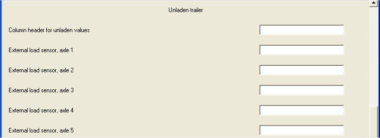
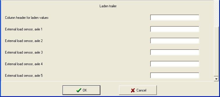
49 The configuration window shown above contains the design as seen for semi- and centre-axle trailers. But if a full trailer is to be configured additional input fields are available. As the 4S/3M full trailer configuration utilises slip control based on the wheel slip of the rear axle(s) no LSF data is available for the front axle. Therefore by default the relevant boxes in the LSF plate will be empty. Should it be required to include information relevant to the front axle(s) this can be entered manually and stored in the *.cfg file for future reference. Explanation of the parameter: Parameter name Description or comments Brake actuator size, axle 1-5 Size/Type of service brake actuator or spring brake actuator installed on each axle e.g. 24 or 24/30 5 characters are available for this information Lever length, axle 1-5 Slack adjuster lever length installed on each axle - this information is only required for S Cam brakes with an external lever. E Mark country code E Mark for the country in which the trailer was approved. E Mark approval number The approval number is obtained from the trailer approval report Laden load of the front axle group 4S/3M full trailer configuration only Unladen load of the front axle group 4S/3M full trailer configuration only Laden air spring pressure at front axle group Unladen air spring pressure at front axle group This only applies to full trailers installed with a 4S/3M configuration and defines the combined laden axle load of the axles controlled by the independent axle modulator. This only applies to full trailers installed with a 4S/3M configuration and defines the combined unladen axle load of the axles controlled by the independent axle modulator. Defines the laden air spring pressure for the front axle group. Defines the unladen air spring pressure for the front axle group. When the trailer is configured to external load sensing, the columns for unladen and laden suspension pressure are replaced by the external load sensor s voltage values corresponding to the unladen and laden trailer. The values can be overwritten freely using two sets of six edit fields corresponding to the unladen and laden case. The first field is for entering the column header, and the next five for entering the values for up to five axles. 49
50 50

51 TEBS rotated 180 If the module is mounted 180 rotated and the concerning Checkmark was set in the configuration screen the Button create rotated ECU Sticker is available in the in the plate information screen and the plate can be printed. 51
52 Changing the Logo Picture In the upper left corner of the LSF plate, the EOL test report and the Fault report there is a picture showing, by default, the Knorr-Bremse logo. There is the possibility to customise this picture, replacing it with the trailer manufacturer s own logo. The picture information is stored in three files in Windows metafile format, with extension wmf. To find the files, go to the installation folder of ECUtalk - usually C:\Program Files\Knorr-Bremse\ECUtalk\ by default using Windows Explorer. Select the ECUApp\EcuProxy\Bin folder, to locate the files lsflogo.wmf, eollogo.wmf and faultlogo.wmf, which are the logo picture files for the LSF plate, EOL test report and Fault report respectively. Before changing the files it is recommended to save a backup copy. Simply overwrite these files with the files containing the company logo, preserving the original file names. The recommended picture sizes are 140x70 pixels for LSF plate logo, and 72x64 pixels for the EOL test and Fault reports. Important! The file names must remain lsflogo, eollogo and faultlogo, and the file format also must be Windows Metafile (file extension wmf)! The Language of the Plates and Reports Every label on the plate is displayed in two languages: English and the selected language of the program. If the selected language is English, the cells on the plate containing data labels will be displayed only in English. 52
53 Chapter 5 Overview of ADL The Auxiliary Design Language (ADL) feature of TEBS allows new auxiliary functions to be realised to control non braking functions of the trailer. ADL programs are developed by Knorr-Bremse and can be written to the TEBS via the ECUtalk along with any associated configuration requirements of the ADL. The ADL programs are executed by an internal interpreter/virtual machine that ensures only carefully controlled inputs and outputs can be used by an ADL program, thereby ensuring that the core braking and safety functions of the TEBS are not compromised. An ADL program may use auxiliary inputs and outputs or interface to other internal auxiliary functions of the TEBS. When a program is downloaded to the TEBS, a message box will be shown defining the required configuration (see below for further explanation). Therefore it is essential that the TEBS is configured correctly; failures will result in the incorrect function of the ADL program, and may also cause unnecessary failures to be logged and the yellow warning signal to flash! 53
 and press the Open button.")
54 5.1 Downloading an ADL File To download an ADL file, select the Load ADL button from the Other functions screen of the Information & Configuration window, select the ADL file (ADL files have a.ads extension) and press the Open button. The ADL program is now loaded into the diagnostic program (note: at this moment it has not been written to the TEBS), a message box will be displayed giving the following information: ADL Program Number: Expected Input Configuration: Expected Output Configuration: Description: Unique number of the ADL file. Auxiliary input Auxiliary output Brief description of the ADL program. Within an ADL there are two kinds of files differing in ADL program number and in size. Version 1 files can be written to ECUs having software versions 520 or 521, while the version 2 ADL files can be written to ECUs having software version 521. Make a note of the expected input and output configuration and click the OK button. Using the configuration menu, set up the auxiliary inputs and outputs to match the expected ADL configuration. Once complete, the configuration and ADL program can be written to the TEBS using the Write to ECU button. Note: ECUtalk does not allow a configuration utilising an ADL if the required auxiliary inputs and outputs are not correctly configured (see the Validation method in Chapter 3) 5.2 Expected Input Configuration An ADL program can use any of the auxiliary electrical inputs (Input A, B or C) of the TEBS. The ADL program may also require built in features such as 'Lift Axle Control. These will be indicated in the message box when an ADL program is loaded. The configuration of the input can be set through the Auxiliary Input tab of the Information & Configuration window. The table below summarises the possible input configurations that an ADL program may request. Input A Input B Input C (up to 520) Input C (521) Configuration Off Yes Yes Yes Yes Pad wear Yes Yes Yes Yes Traction Help Yes Yes No Yes Disable lift axle control Yes Yes No Yes ADL Digital input Yes Yes Yes Yes ADL Analogue input (0 to 5V) Yes Yes No Yes * ADL Analogue input (0 to Yes Yes No Yes 24V) * External LSF sensor * Yes Yes No No Advanced LAC * Yes Yes No Yes *) not available in ECU SW versions below 521 It is important to note that failure to set the correct input configuration for ADL will result in an ADL Input Configuration Error being stored in the failure memory, and the yellow warning lamp will flash when the vehicle is stationary. 54
 and Magic Eye). The expected output configuration will be indicated in the message box when the ADL program is loaded.")
55 5.3 Expected Output Configuration An ADL program can use any of the auxiliary outputs (AUX1, AUX2, AUX3, AUX4 and AUX5), it may also use one of the existing functions of TEBS (Lift Axle Control, Reset to Ride (LAC/RTR) and Magic Eye). The expected output configuration will be indicated in the message box when the ADL program is loaded. If the ADL program uses an auxiliary output directly, then a message box will display a request to configure (or connect) the ADL outputs (ADL-OPA, ADL-OPB, ADL-OPC or ADL-OPD) to an auxiliary output. The ADL program is not concerned about which auxiliary output pin the function is connected to. Therefore, the trailer builder should select the most appropriate output. The configuration of the auxiliary outputs can be set through the Auxiliary Output tab of the Information and Configuration window. If an ADL program uses an existing LAC/RTR function, a message box will display a request to configure (or connect) the LAC/RTR control, this can be set through the Other functions tab of the Information and Configuration window. If the ADL program uses the Magic Eye function, a message box will display a request to configure (or connect) the Magic Eye, this can be set through the Other Functions tab of the Information and Configuration window. 55

56 5.4 ECUtalk and ADL During the initialisation of ECUtalk, the program reads the ADL code from the ECU. When the configuration is stored in a file, the ADL will also be stored. Therefore the next time the file is loaded, the ADL program will also be loaded and finally stored into the ECU. Once the ADL is written to the ECU, the additional description will not be available from the ECU as this is only stored in the *.ads ADL files and not in the ECU. Identification of ADL For future identification the following ADL information is available: Explanation of the lines: Instruction set version ADL target ADL program Is ADL program loaded The ADL interpreter version number in the ECU software The target ECU type, 1 is TEBS before software version 521, and 7 for 521. Other figures are associated with other electronic systems. Identifies the functionality of the ADL software. Indicates that a valid ADL file is loaded into the ECUtalk memory. The ADL was either read from an ECU or loaded from a file. Clearing the ADL Program An ADL control function can be removed from the ECU with the use of Clear ADL. The change will take effect when the new configuration is written to the ECU. If the ADL is cleared but not the associated auxiliary input or output parameters, ECUtalk will display a warning before attempting to store the parameter set into a file or ECU. 56

57 The system check will be opened by a click on the icon shown in the following figure. Chapter 6 System Check Pages To carry out system checks, ECUtalk will over-ride the operation of the TEBS to enable checks of the configured functions to be carried out. However, there are certain limitations that must be observed as follows: 2S/2M and 4S/2M System Configurations: 2S/2M A braking demand must not be present and all wheels with wheel speed sensors must be stationary prior to any check being carried out. 4S/2M A braking demand must not be present and at least one of the axles equipped with wheel speed sensors must be stationary prior to any check being carried out. 4S/3M Configurations: 4S/3M A braking demand may be present and any axle installed with wheel speed sensors may be rotating prior to any check being carried out. Note: Failure to observe these conditions will result in the specific check not being carried out and/or a fault being recorded. Certain options within ECUtalk automatically suspend control from the TEBS when specific tests are carried out, allowing direct or indirect switching of the functions/devices. When checks are made of auxiliary functions, initially the function is controlled by the ECU but can be switched to manual direct or indirect control. When moving between windows of the system check, the system control state is always returned to control from the ECU, therefore any previously energised valves are turned off, any output signal is cleared and simulated speeds or pressures are returned to zero. The following table defines the tests that may be carried out during System Check: Test Pressure component check Wheel speed sensor checks Auxiliary output checks Axle modulator test Auxiliary inputs check RSP installation test Power supply and WL test Configuration Always present irrespective of the system configuration Always present irrespective of the system configuration Always present when a specific auxiliary function is configured Only available when 4S/3M ABS is configured Tests can only be carried out for Pad Wear, Traction Help, Disable lift axle control and Advanced LAC irrespective of whether other sensor inputs are configured Always present when RSP is configured Always present irrespective of the system configuration 57
58 6.1 Pressure Component Check In the Pressure component check window of the System Check section, it is possible to simulate the operation of the load sensing function and apply specified pressures to the left and right brakes. However when any pressure component check is being carried out the following conditions apply: 2S/2M: A braking demand must not be present and all wheels with wheel speed sensors must be stationary prior to any check being carried out. 4S/2M: A braking demand must not be present and at least one of the axles equipped with wheel speed sensors must be stationary prior to any check being carried out. 4S/3M: A braking demand may be present and any axle installed with wheel speed sensors may be rotating prior to any check being carried out. When a pneumatic driver demand is present during this check the pressure generated at the brakes will be based on the highest of the two possible demands i.e. pneumatic or ECUtalk. Note: Failure to observe these conditions will result in the specific check not being carried out and/or a fault being generated. System Response to Actual Driver Demand In this window it is possible to read the actual pressures recorded within the respective elements of the braking system i.e. supply pressure, air spring pressure etc. Therefore when an actual braking demand is present the TEBS will generate a pressure at the brake actuators that is dependent on the actual air spring pressure (load condition) and pneumatic or CAN braking demand. However the pressure generated at the brake actuators will also depend on the braking demand status when the system was first powered as follows: System power up with braking demand present: Brake Demand Software Pneumatic Only Pneumatic + CAN CAN only Level Back up LSF Based on Actual Load Back up LSF Based on Actual Load LSF Based on Actual Load Pre X X X With Brake Assist and above P Demand >5bar for more than 2secs P Demand <5bar with Brake Assist P Demand >5bar for more than 2secs P Demand <5bar with Brake Assist X With Brake Assist System power up without braking demand present: Brake Demand Software Pneumatic Only Pneumatic + CAN CAN only Level Back up LSF Based on Actual Load Back up LSF Based on Actual Load LSF Based on Actual Load Pre X Without Brake Assist X Without Brake Assist X Without Brake Assist and above X Without Brake Assist X Without Brake Assist X Without Brake Assist Note: The above characteristics are for information only and are generated independent of ECUtalk and only apply when no wheel speeds are present. 58

59 Simulation of the Load Sensing Function In this test mode it is possible to simulate a given load condition and the driver demand pressure after which the brake actuator pressure is generated in accordance with the programmed load sensing characteristics. (The varaibles are configured in the Braking window) To proceed, the "LSF Simulation" in the upper left corner of the screen must be selected. The following will be displayed: User-controls, including the inputs to simulate air spring pressure (within the configured pressure range) or the corresponding load percentage, driver demand-pressure and a Brake button to apply the brakes. Current pressure status including system pressure, left and right brake actuator pressures, air spring pressure and/or load percentage and braking demand pressure. The diagram shows the configured LSF characteristics relative to braking demand for unladen and laden conditions. On the right of the diagram the configured unladen and laden air spring pressures or voltage values of the external load sensor are also displayed. To produce a given braking demand, enter the required air spring pressure or load percentage and demand pressure. The air spring pressure value is used in case of TEBS software versions below 521. For the version 521 the air spring pressure is replaced by the load percentage independent of whether internal or external load sensing is used. To apply the brakes, select the Brake button. The diagram will show the pressure characteristics for the simulated load condition. In case of external load sensing the minimum and maximum air spring pressure values on the diagram are replaced by the minimum and maximum voltage values of the load sensor set for the unladen and laden trailer respectively. The actual air spring pressure value is displayed if the internal load sensing is used, while in case of external load sensing, the actual voltage of the load sensor can be seen. A blue square will appear which defines the expected brake actuator pressure for the simulated test condition. The TEBS Module will now generate a pressure at the left and right brake actuators; a yellow circle represents these pressures. A comparison can be made between the expected and actual brake actuator pressures. The actual recorded pressures can be read from the on screen table. To release the brakes select the Release button. 59


60 Manual Brake Control In this mode it is possible to generate a specific pressure at the left and right brake actuators irrespective of the load condition. However the conditions defined above should be noted. This function-mode can be chosen in the sub item Pressure component check. Select "Manual brake control" and the user-controls will change to "Left Pressure" and "Right Pressure" input fields and the configured load sensing characteristics will be removed from the diagram. Having set the desired delivery pressure values for the left and right sides in the input fields, select the "Brake" button. Two squares will appear on the diagram (blue for left and yellow for right) representing the desired pressure values. The TEBS Module will now generate the corresponding pressures at the left and right brake actuators; the blue and yellow circles represent these pressures. The actual recorded pressures can be read from the on screen table. To release the brakes select the Release button. If this test is performed while an actual driver braking demand is present the behaviour characteristics are different to those defined above. During a pneumatic system check an actual control line braking demand must not be present otherwise it will not be possible to produce the required brake actuator pressure via ECUtalk. If the ECU is rotated 180 degree - the pressure values shall be displayed correctly at the sides (i.e. pressure at left side of the vehicel is under 'Left pressure' label, while pressure at right side under 'Right pressure') 60


61 6.2 Wheel and Air-Gap Speeds In the Wheel Speed Sensor checks window, the integrity of the wheel speed sensor installation can be checked by measurement of actual wheel speed and determination of the air gap speed i.e. the speed at which the ECU sees an acceptable wheel speed sensor output from each wheel installed with a wheel speed sensor. Note: The air-gap speed is the lowest wheel speed the TEBS can measure during this test. The number of sensors which are available for checking is dependent on the system configuration as follows: All system configurations: Sensors SL and SR are displayed 4S/2M and 4S/3M configurations: Sensors SAL and SAR displayed Note: The actual location of the wheel speed sensors on the trailer may differ from those shown in the diagram. The diagram illustrates the selected system configuration; see Information window. To obtain the air gap speeds, the following message will appear on the screen outlining the test procedure. 61

62 When required, the Reset air gap speed button clears the previously recorded air gap speeds. When an air gap speed exceeds 8 km/h, a warning message appears on the screen and the sensor to pole wheel gap should be adjusted and the test repeated: ECUtalk also shows a traffic light system to provide a visual indication of the air gap status: Green: The air gap speed is below 4 km/h Yellow: Between 4-8 km/h Red: Above 8 km/h. The test should be carried out separately on each wheel. At the start of this check, the wheel should be stationary. Then it should be carefully rotated and its speed slowly increased. Note: If the wheel is accelerated rapidly, an incorrect air gap speed will be recorded which will be above the maximum limit - irrespective of the actual air gap. Check the corresponding field where the actual wheel speed and calculated air gap speed will be displayed. For software version 520 and above, after the wheel has been accelerated and an air gap speed recorded, the wheel must be allowed to decelerate naturally to a stop. The air gap speed is then reassessed and the lowest value displayed, based on the measurements during the acceleration and deceleration phases. Note: In Demo Mode the values are random values and only represent the continuous monitoring functionality of ECUtalk. 62

63 TEBS rotated 180 If the ECU is rotated 180 degree - The SR and the SAR sensed wheels rotates with the ECU i.e. SR and SAR display the left wheel speeds - The SL and the SAL sensed wheels rotates with the ECU i.e. SL and SAL display the right wheel speeds 63

64 6.3 Auxiliary Function Tests Selecting the "Auxiliary function tests" tab of the System check screen, the operation of certain auxiliary output functions can be checked. Each check verifies the output from the TEBS, the cabling and the actual function of the component connected to the output. It is only possible to check the following auxiliary functions: ISS Integrated Speed Switch RTR Reset to Ride LAC1 Lift Axle Control 1 LAC2 Lift Axle Control 2 C3 C3 speed signal Note: Only a configured auxiliary function can be checked. The auxiliary functions are listed in the upper left corner. Those functions that are configured and may be checked are defined in bold text. Any functions that are not configured and therefore cannot be selected are in grey text. The function to be tested must first be selected by clicking on the button to the left of the function name. Then select the method by which the function is to be checked from following options: Control by ECU: This is not a method of checking the function but is only a default selection indicating that the function is currently controlled by TEBS. Speed Simulation: By utilising a speed simulation it can be checked if the function responds correctly to the speed input. If the external load sensor is configured then this option cannot be operated for LAC. Direct Switch: The operation of the auxiliary function is realised by selecting the Direct Switch button. 64
65 Testing with the "Direct Switch" Using the "Direct switch" method is the same for all outputs. An "On/Off" button appears on the screen, by which it is possible to directly activate / deactivate the selected auxiliary function. When the On/Off button is selected, the operational status is displayed on the screen and the selected auxiliary function will be seen to operate as follows: Lift Axle Control: ON: Lifting axle(s) will raise OFF: Lifting axle(s) will lower Reset to Ride: ON: Operating lever will pop out. OFF: Signal is terminated but no reaction is observed. Note: The above functions will only operate when adequate air pressure is available. In the case of Reset to Ride the operating lever must first be pushed in. 65


66 Testing ISS with Speed Simulation When the "ISS" and "Speed simulation" have been selected, a slider-control appears, automatically displaying the configured speed threshold for the ISS. Move the slider to simulate a speed above the configured threshold - displayed by a blue line in the slider. Once the simulated threshold speed has been exceeded, the ISS switch will become active. ISS can be configured to switch OFF at 90%, 80%, 60% or 20% of the configured threshold speed, (see Auxiliary outputs window). The ISS will switch off when the slider has been moved below the configured percentage of the speed threshold. Testing "Reset to Ride" with Speed Simulation When the "Reset to Ride" and "Speed simulation" have been selected, a slider-control appears, automatically displaying the speed threshold for RTR. First push in the operating lever on the raise/lower valve, and then move the slider to simulate a speed above the configured threshold (displayed by a blue line in the slider). Once the simulated threshold speed has been exceeded, the RTR switch will become active and the operating lever will pop out. To repeat the test, move the slider back to zero and repeat the above procedure. 66

67 Testing Lift Axle Control with Speed- and Load- Simulation Select "Speed Simulation" and either "Lift Axle Control 1" or "Lift Axle Control 2" after which two slider-controls appear, one for simulated vehicle-speed, and one for simulated air spring pressure. On the second slider the unladen and laden configured air spring pressures are displayed (the blue line represents the range between the two extreme values). These values will have been defined during configuration of the load sensing braking functions. Move the air spring slider to a value that results in the axles controlled by LAC1 or LAC2 lifting. The actual air spring pressure at which the axle(s) rise will be dependent upon the configuration values (see Auxiliary outputs window). Lifting of the axle(s) will take some time, due to the changes in the air spring pressure to reflect the change in axle load. Move the air spring slider to simulate an increase in air spring pressure. When the maximum configured air spring pressure value is reached (displayed to the right of the sliders), the lifted axle(s) will begin to lower. Notes: When LAC1 and LAC2 are both configured, they cannot be tested separately with speed simulation, i.e. they can only be tested as one functional unit. If the load sensing is configured to external load sensor, the speed simulation is not available, this function can only be checked by a direct switch. If lift axle control is active at standstill, the slider for vehicle-speed is ineffective If lift axle control is NOT active at standstill, the slider for vehicle speed must be set above the RTR speed limit to simulate the vehicle being driven. The lift axle control will be effective after an RTR signal has been generated. This applies even if RTR is not configured and in this case there is a default speed threshold. Effect of ADL on Lift Axle Control and RTR When an ADL function is configured, and speed simulation is being used to check the operation, an unexpected lift axle or RTR control may be experienced if the checkbox "Enable ADL-LAC/RTR Control" in the Other functions window has been set. In this case check that the ADL configuration is correct. 67
 that is speed dependent. TEBS can provide this Signal which may be used by other electronic systems e.g. electronic levelling control.")
68 Testing "C3" with Speed Simulation The C3 signal can only be tested when the option has been configured to an AUX output. The C3 signal is a standard square wave pulse width modulated signal (PWM) that is speed dependent. TEBS can provide this Signal which may be used by other electronic systems e.g. electronic levelling control. The test procedure defined below will produce the PWM signal at a selected speed and the operator must verify that the system receiving the signal reacts accordingly. It is not possible for the TEBS to verify the function of the additional control system. 1 2 To simulate the PWM test speed, open the system check page for Auxiliary function test and select C3 speed signal. (1) To simulate the speed, select Speed simulation in the field below and drag the slider in the Vehicle speed [km/h] area until the required speed for the simulation is reached. (2) 68
 I/O status The screen also shows a picture of the 7-pin ISO7638 connector where the pin numbers, associated functions and cable colours are defined.")
69 6.4 Power Supply and Warning Lamp Check In the Power supply and WL check window the following checks can be carried out: Voltage levels to the ECU and Modulators Warning lamp operation Magic Eye operation (when configured) I/O status The screen also shows a picture of the 7-pin ISO7638 connector where the pin numbers, associated functions and cable colours are defined. ISO7638 Supply Check In the Power Supply window, the actual voltages available from pin1 (modulator supply) and pin 2 (ECU supply) are displayed. The ability to check the Magic Eye depends on whether the diagnostics session is using the K Line option in which case the picture of the Magic Eye and selection button will not appear. It is only possible to check the function of the Magic Eye when diagnostics via 24V CAN is used. Warning Lamp Check A check of the warning signal is carried out by selecting the Switch warning light ON or Switch warning light OFF button and checking the actual operation of the warning signal in the towing vehicle. Note: Failure of the warning signal to operate may not be as a result of a fault on the trailer but due to a fault on the towing vehicle. Note: The symbol of the warning signal on the screen being switched ON or OFF does not represent the actual warning lamp operation but only an indication of assumed status. 69
70 Magic Eye Check It is only possible to check the function of the Magic Eye when it has been configured and connected to the associated ECU connections. If the Magic Eye is not configured, the picture will not appear on the screen. A check of the operation of the Magic Eye is carried out by selecting the Switch Magic Eye ON or Switch Magic Eye OFF button and checking the actual operation of the Magic Eye mounted on the trailer. Note: The symbol of the Magic Eye on the screen being switched ON or OFF does not represent the actual Magic Eye operation but only an indication of assumed status. Stop Lamp Supply Check The check of the availability of the stop lamp supply must be carried out independent of ECUtalk, the test procedure is defined on the screen and repeated below: 1. Disconnect the ISO7638 supply and connect the ISO1185 (24N). 2. Fully apply the foot brake control of the towing vehicle, turn on the ignition. 3. Air will then be heard exhausting from the Modulators. 4. Release brakes, re-connect the ISO7638 and proceed with diagnostic system check. Note: It is only necessary to carry out this check when the stop lamp supply is connected to the ECU. With ECU SW 521 the stoplight test can be carried out during the EOL test. Input and Output Status Check The white table shows the response of the I/O status check. This table contains the status of the inputs and outputs and the recorded voltage values for inputs. The data displayed depends on the ECU software version number, the configuration of the inputs and the supply voltage of the ECU. This may mean that the displayed input voltage differs from the actual voltage. 70

71 6.5 Auxiliary Input Check In the A/D input check window of the System Check section, the cabling and configuration of a configured auxiliary input may be checked. The screen displays the maximum capability of 3 inputs even in the case when the Input C is not supported by the ECU software level. Note: Only when a specific Auxiliary Input is configured will the associated picture appear. Functional checks are only possible with the following Auxiliary Inputs : Pad wear Traction Help Disable lift axle control Advanced lift axle control When Pad wear is configured, the picture displayed informs about the wear status: Wear not tested Wear OK Wear not OK It is not possible to carry out validation checks on any other auxiliary input. In the test page window the input to be checked can be selected, as well as the operating buttons including an option to introduce a time delay. The Auxiliary Input check is carried out as follows: 1. Select the input function to be checked. 2. Use the Apply for open switch to start the test. There will be a time delay dependent on the value defined as Delay until state check [s] time to allow the switch to operate. After the time delay has elapsed, ECUtalk retrieves the switch status information from the TEBS and displays the result on the screen. 71

72 3. Use the Apply for closed switch to revert the test condition back to its original state. After the time delay has elapsed, ECUtalk retrieves the switch status information from the TEBS and displays the result on the screen. 4. To repeat the test use the Clear test result button to clear the existing results and repeat the tests as necessary using the above procedure. Test steps for Advanced LAC ECUtalk provides all necessary functionality to check the Advanced LAC, if this has been configured to an Input. Advanced LAC provides both Traction Help and Disable LAC functions from a single switch, where the actuation time of the switch defines which function is selected. Therefore both functions need to be checked: 1) Check the integrity of the switch, wiring and connection to the input of TEBS. 2) Check the function Disable LAC when the switch is activated for more than 5 seconds. 3) Check the Traction Help function when the switch is activated for less than 5 seconds. 72
, the following message should be displayed.")
73 Test of switch Perform the button test using the System check function of ECUtalk. Result of Input test: If the button condition closed is identified for the expected input (shown as A in the example above), the following message should be displayed. Input A closed: OK If the condition is identified in the Input B field, the cabling is mis-matched! Check X2 connector Pins 5 and 6 are correctly wired. If the button condition closed is not identified a message will be displayed. Input A closed: Not OK 73
. Wait until the lift axle(s) are raised.")
74 Test Disable Lift axle Control (LAC) Simulate the load with ECUtalk, changing the value for the air bellow pressure for unladen case (< 33%). Wait until the lift axle(s) are raised. Activate the switch for more than 5 seconds to enable Disable LAC : 74
75 Testing of the function Disable LAC on input A (or B) is now complete. 75
 just to exclude that the axle is lifted by normal lift axle control. Activate the switch for less than 5 seconds to enable TCH.")
76 Test Traction help (TCH) Simulate the load with ECUtalk by changing the air bellow pressure to a value corresponding the laden case (>64%) just to exclude that the axle is lifted by normal lift axle control. Activate the switch for less than 5 seconds to enable TCH. 76
77 Testing of the function TCH on Input A (or B) is now complete. 77

78 Test if TCH is deactivated while driving Simulate for a short time a speed of 40 km/h, this will end the function TCH. Now, after the system has realized the laden situation, the lift axle will lower again. Note: If the programmed RTR speed is met by the simulation, the RTR Valve is actuated for a short time. This should also be checked if possible. After the test has been performed, the load simulation will be stopped by leaving the function system check and end the program ECUtalk. Results will be written to a test report. Advanced LAC is enabled when the signal changes from closed to open as shown above. (i.e. with the button in the open position again.) 78

79 6.6 RSP Installation Check In the RSP Installation check window of System Check section, the installation of the TEBS Module is checked. If the RSP is not configured, the test page is not available. Note: Before starting the test, ensure the trailer is standing on a flat horizontal surface. For the RSP function to operate efficiently the parameters programmed into the ECU must be correct for the trailer on which the system is installed! ECUtalk is able to verify the installed roll angle it is not able to verify the so-called tilt angle (see the above picture upper left side). The roll angle of the EBS must be installed within the limits +/-5. The on screen display will show the actual installed roll angle. When entering the RSP Installation test window, the installation check is carried out automatically. The measured offset is used to calibrate the Lateral Acceleration Sensor within the ECU. Should the measured angle exceed the above limits, the calibration of the Sensor will not take place and it will be necessary to check the actual TEBS installation on the trailer otherwise the RSP function will not operate efficiently. 79

80 6.7 Axle Modulator Valve Test (4S/3M configurations only) In the Axle Modulator Test window of system check section, the installation and function of the axle modulator valve may be checked. This check is only applicable to 4S/3M configurations that utilise a remote axle modulator valve. It is not available for 2S/2M or 4S/2M configurations. The upper left area of the screen (see above) contains two buttons for directly energising the solenoids within the axle modulator valve to reproduce Hold and Exhaust states. The third Pressure Rise state is produced when both of the Hold or Exhaust solenoids are de-energised to allow pressure to be increased in the brake actuators. The screen also displays the status of: Coupling head pressure pneumatic braking demand. Left wheel speed from Sensor SAL. Right wheel speed from Sensor SAR. 80

81 To ensure that damage to the solenoids does not occur from excessive solenoid energising, ECUtalk will only permit a solenoid to be energised for a maximum of one minute. The buttons, once selected, remain selected to represent the operating state of the valve. To de-energise a solenoid and thereby end a state, the same button must be selected again. The checks that may be carried out are as follows: Hold command: Selecting the Hold button will result in the pressure that was in the brake actuators at the point of energisation to remain unchanged provided that the braking demand does not reduce to a value below that which is held in the brake actuators otherwise the brake activator pressure will follow the demand pressure: With no braking demand the Hold solenoid is then energised: The wheels associated with sensors SAL and SAR can be rotated. Apply a braking demand and the wheels SAL and SAR are still able to be rotated. Exhaust command: Exhaust solenoid energising with or without braking demand: Any brake actuator pressure is exhausted irrespective of change in braking demand in this case the wheels associated with wheel speed sensors SAL and SAR can be rotated. Pressure Rise state: When both Hold and Exhaust solenoids are de-energised the pressure in the brake actuators will rise to a value equivalent to the demand pressure. Brake demand present: The wheels associated with wheel speed sensors SAL and SAR cannot be rotated. Brake demand not present: The wheels associated with wheel speed sensors SAL and SAR can be rotated. 81


82 Chapter 7 End of Line (EOL) Test Before starting the EOL test it is recommended that any faults are corrected and erased from the TEBS memory. This will ensure that only faults detected during the EOL test are recorded in the test report which is produced after the EOL has finished. To start the EOL test procedure, select the EOL icon from the toolbar. 7.1 The EOL Test Window The EOL window has 4 different areas: Tests to be carried out and associated results Control and navigation buttons Fault status Main result window showing the status of the current test Test Sequence The test sequence window shows the order in which the EOL tests are carried out; the actual tests carried out will depend on system configuration. The result of each test is displayed adjacent to its description for the current session: Explanation of the symbols: - The test was successful - The test has failed - The test was interrupted. - The current test window 82
83 The test sequence reflects the system and may be changed via the Trailer diagnostics Preferences EOL test parameters menu items. The EOL test window must be closed after a modification and re-opened again for the changes to be effective. Otherwise the current status will remain active. Once the test sequence has been defined, the EOL test runs automatically without user intervention. Control and Navigation Buttons The function of the respective navigation buttons is as follows: Start : When entering the End EOL test window, only the Start button is available for selection, clicking on this button will start the test. Stop : During any test the only button that can be selected is the Stop button and, when selected, the current test will stop. To continue with the test the Continue button must be selected. Continue : When the current test is stopped it is possible to carry on with the check by selecting the Continue button. Retry : Should a particular test fail and it is necessary to repeat a test, selection of the Retry button will restart the current test. This function allows a detected fault to be rectified and the check repeated. Previous : Scrolls back to tests already carried out. Next : Scrolls forward to tests not yet carried out. Continue run : When a check has been made that is out of sequence, selection of the Continue run button will continue the test sequence from the point when the sequence was interrupted. Restart : When selected, the EOL test will be carried out from the beginning. Create Report : On completion of the EOL test a report of the test results can be viewed by selecting the Create report button. Fault Status When a system fault is detected by the ECU, the presence of the fault is shown on the screen in the bottom left corner: Details of the actual fault are not displayed; however these may be accessed via the main Fault window selected from the main toolbar. System fault status is obtained from the TEBS ECU prior to the commencement of the EOL tests. Should an ECU fault be present during the EOL test, the above window will not display the fault condition, however the EOL test being carried out when the error was detected will result in a fail. 83
84 Main Test and Results Screens For each test carried out, the screen will provide a description of the test and, where appropriate, an illustration to assist the user. The actual screen displayed will depend on the system configuration and the position within the EOL test sequence. The following table defines all of the tests that may be carried out during the EOL test: Test step System pressure test Warning lamp test RTR test ISS test LAC1 test LAC2 test RSP active output test ABS active output test TOC output test C3 test LSF test Ext. LSF test SL Sensor test SAL Sensor test SAR Sensor test SR Sensor test Stop lamp test Disable lift axle control test Traction Help test ALAC test External load sensor test RSP installation test Axle modulator Valve test ADL Output A test ADL Output B test ADL Output C test ADL Output D test ADL - Analogue Input (0-5V) test ADL - Analogue Input (0-24V) test ADL digital input test Configuration Test carried out irrespective of system configuration Test carried out irrespective of system configuration Test carried out when configured to auxiliary output Test carried out when configured to auxiliary output Test carried out when configured to auxiliary output Test carried out when configured to auxiliary output Test carried out when configured to auxiliary output Test carried out when configured to auxiliary output Test carried out when configured to auxiliary output Test carried out when configured to auxiliary output Test carried out irrespective of system configuration, when internal load sensing is used Test carried out irrespective of system configuration, when external load sensing is used Test carried out irrespective of system configuration 4S/2M See comments below 4S/2M See comments below Test carried out irrespective of system configuration Tested when selected from the Preferences - EOL window Test carried out when configured to a Sensor input Test carried out when configured to a Sensor input Test carried out when configured to a Sensor input Test carried out when configured to a Sensor input, and external load sensing is used Test carried out when RSP is configured Test carried out when 4S/3M system is configured Test carried out when configured to Auxiliary output Test carried out when configured to Auxiliary output Test carried out when configured to Auxiliary output Test carried out when configured to Auxiliary output Test carried out when ADL is configured to Auxiliary input Test carried out when ADL is configured to Auxiliary input Test carried out when ADL is configured to Auxiliary input Note: For a 4S/3M configuration, the SAL/SAR tests should be carried out in the Axle Modulator Valve test. 84

85 System Pressure Test Before commencing the actual EOL configuration tests, a check of the available reservoir pressure is made. In all cases this value must be at least 7.5bar to ensure that all tests can be carried out without a failure being recorded due to low reservoir pressure. If the reservoir pressure is below the minimum value, the test will be recorded as failed. It is recommended that the load sensing pressure check be carried out immediately after the warning lamp check to ensure maximum reservoir pressure is available. However, a second check of the available reservoir pressure is made prior to the load sensing check being carried out irrespective of its position within the test sequence. Warning Lamp Test During this test ECUtalk instructs the TEBS ECU to transmit a signal to illuminate the warning lamp in the driver s cab. This check verifies that the signal transmitted to the towing vehicle is illuminating the warning lamp. The warning lamp test is carried out in two steps: Step 1: ECUtalk asks the TEBS ECU to transmit a signal to illuminate the warning lamp in the cab of the towing vehicle via pin 5 of ISO7638. The user is asked to confirm that the warning lamp is illuminated: Step 2: ECUtalk asks the TEBS ECU to switch off the signal to the warning lamp in the cab of the towing vehicle. The operator is asked to confirm that the warning lamp has been switched off: The result of the test is dependent upon the operator making the correct confirmation of the warning lamp operation. Note: A failure of the warning lamp check may be due to a fault with the towing vehicle and not the trailer 85

86 Integrated Speed Switch Test (ISS) ECUtalk asks the TEBS ECU to switch the configured auxiliary output voltage from 0V to 24V (24V to 0V in the case of ISS Inverted ) to simulate the operation of the ISS speed switch. The functionality of the device associated with this switch is user definable and therefore dependent upon the specification of the trailer. The ISS test is carried out in two steps: Step 1: ECUtalk asks the TEBS ECU to transmit the ISS signal from the configured auxiliary output. The operator is asked to confirm the status of ISS function. Step 2: ECUtalk asks the TEBS ECU to switch off the ISS signal from the configured auxiliary output. The operator is asked to confirm the status of ISS function. The result of the test is dependent upon the operator making the correct confirmation of the ISS operation. Note: The screen showing the ISS signal is only a symbol and does not reflect the actual operation or status of the ISS function. Reset to Ride (RTR) Test ECUtalk asks the TEBS ECU to switch the configured auxiliary output voltage from 0V to 24V to simulate the operation of the RTR switch. This check verifies that the signal transmitted to RTR valve fulfils the suspension reset function. Note: The screen showing the RTR valve is only a symbol and does not reflect the actual operation or status of the valve. 86


87 The RTR test is carried out as follows: Step 1: A request is made for the operator to push in the control lever on the RTR valve and to confirm that the operation has been carried out. Clicking the Cancel button will result in failing the test. Step 2: Note: ECUtalk asks the TEBS ECU to transmit the RTR signal from the configured auxiliary output. The operator is asked to confirm the status of RTR function by observing the reaction of the RTR control lever, which should pop out. The displayed time delay value is the configured RTR valve actuation time system parameter. 87
88 The result of the test is dependent upon the operator making the correct confirmation of the RTR operation. Confirmation may be made at any time once verification has been made, irrespective of the programmed delay time. Rollover Stability Program (RSP) Active Output Switch Test ECUtalk asks the TEBS ECU to switch the configured auxiliary output voltage from 0V to 24V to simulate that when RSP becomes active the RSP Active switch signal is available. This check verifies that the signal transmitted to the device controlled by the RSP Active signal is functioning correctly. The RSP Active test is carried out as follows: Step 1: ECUtalk asks the TEBS ECU to transmit the RSP Active signal from the configured auxiliary output. The operator is asked to confirm the status of RSP Active function. Step 2: ECUtalk asks the TEBS ECU to switch off the RSP Active signal from the configured auxiliary output. The operator is asked to confirm the status of RSP Active function. The result of the test is dependent upon the operator making the correct confirmation of the RSP Active operation. ABS Auxiliary Output Test ECUtalk asks the TEBS ECU to switch the configured auxiliary output voltage from 0V to 24V to simulate that the ABS is active so the ABS Active switch signal is available. This check verifies that the signal transmitted to the device controlled by the ABS Active signal is functioning correctly. The ABS Active test is carried out as follows: Step 1: ECUtalk asks the TEBS ECU to transmit the ABS Active signal from the configured auxiliary output. The operator is requested to confirm the status of ABS Active function. Step 2: ECUtalk asks the TEBS ECU to switch off the ABS Active signal from the configured auxiliary output. The operator is asked to confirm the status of ABS Active function. 88
 voltage from 0V to 24V to simulate the operation of the LAC switch.")
89 The result of the test is dependent upon the operator making the correct confirmation of the ABS Active operation. Lift Axle Control Test ECUtalk asks the TEBS ECU to switch the configured auxiliary output(s) voltage from 0V to 24V to simulate the operation of the LAC switch. This check verifies that the signal transmitted to LAC control valve fulfils the lift-axle control function. Note: Where a lift axle control valve is connected to more than one lift axle, all lifting axles connected to the valve will lift and lower when the corresponding signal is transmitted. Where two different valves control lift axles, LAC1 and LAC2 lift axle control must be checked independently. The screen showing the trailer is only a symbol and does not reflect the actual operation or status of the lift axle control. The LAC test is carried out as follows: Step 1: ECUtalk asks the TEBS ECU to transmit the LAC control signal from the configured auxiliary output. The operator is asked to confirm that the lift axle(s) has lifted. Step 2: ECUtalk asks the TEBS ECU to terminate the LAC control signal from the configured auxiliary output. The operator is asked to confirm that the lift axle(s) has lowered. The result of the test is dependent upon the operator making the correct confirmation of the lift axle control. 89


90 Kilometre Counter Test (TOC) To check that the trailer occurrence counter (24V pulse for every kilometre travelled) is functioning, it is necessary to have it connected to a device that is able to output incremental changes. The check is carried out as follows: Step 1: Before commencing this check, the operator should note the current reading on the kilometre counter. ECUtalk will ask if the operator is ready for the counter to be incremented. Selecting Cancel will result in a test failure. Step 2: After confirmation by the operator to proceed, the ECU transmits a request to TEBS to send a single pulse from the configured Auxiliary Output. The operator will be asked to confirm if the counter has incremented. The result of the test is dependent upon the operator making the correct confirmation that the counter has actually incremented. No confirmation will result in a test failure. C3 test The EOL test does not verify the C3 function but asks the operator to confirm that a check was carried out during the system checks and, if so, to confirm whether the result was positive. When the operator confirms a positive response to the on-screen request, it is assumed that the test has been successfully carried out: Wheel Speed Sensor and Modulator Correlation Tests 90

91 All system configurations will have checks carried out on sensors SL and SR. In the case of 4S/2M and 4S/3M configurations, additional checks are carried out relative to sensors SAL and SAL. Full test During the test, checks are carried out that verify the correlation of the wheel installed with a wheel speed sensor and the pressure modulator that controls the pressure to the associated brake. A failure would be recorded when the expected correlation is not realised. The wheel speed sensor test is carried out as follows: Step 1: The operator must first accelerate the wheel associated with a single wheel speed sensor. Step 2: Step 3: Note: Once a wheel speed is registered the message asking for the wheel to be rotated will disappear. ECUtalk then asks the TEBS ECU to generate a brake pressure from the modulator corresponding to the wheel speed sensor signal being received. If the correlation is correct, the braked wheel will decelerate and lock and the wheel speed signal is no longer generated. Should the wheel not decelerate the correlation between Sensor and modulator is incorrect. When the wheel is rotated a secondary check of the Sensor air gap speed is carried out speed at which an acceptable sensor signal is generated. After the automatic brake application and the wheel is stationary, ECUtalk transmits a signal to the TEBS to release the brake. After the pressure in the brake has been exhausted, the operator will again be requested to rotate the wheel. This verifies that the brakes have been released. If the message requesting that the wheel be rotated remains on the screen for 60 seconds, a time out occurs and test failure is recorded Apart from the requests for the operator to rotate the wheel, the test is automatic and requires no further input or confirmation of function from the operator. When it is requested to rotate a specific wheel ensure that all other wheels equipped with wheel speed sensors are stationary otherwise an incorrect result may be recorded 91

92 TEBS rotated 180 If the ECU is rotated 180 degree - The SR and the SAR sensed wheels rotates with the ECU i.e. SR and SAR display the left wheel speeds - The SL and the SAL sensed wheels rotates with the ECU i.e. SL and SAL display the right wheel speeds 92

93 Simplified test In the simplified test, the sequence is the same except that step 3 above is not carried out therefore a check is not made to ensure that the braking system is able to exhaust the pressure from the brake actuator and release the brake. From the menu the Trailer Diagnostic > Preferences > EOL Parameter > User test EOL file name, the option of the full test or the simplified test can be selected. Load Sensing Function Test (LSF Test and Ext. LSF Test) During this test ECUtalk asks the TEBS ECU to generate pressures in the left and right brake actuators. The actual pressures generated are those associated with the configured pressure values programmed into the TEBS and are representative of the laden and unladen trailer. Prior to commencing this test, a check is made to ensure that adequate reservoir pressure is available so that the test may be conducted without a fault being recorded due to low reservoir pressure. Once the load sensing pressure check window has been accessed, the respective tests are carried out automatically with the TEBS ECU providing information of the actual pressures generated. No interaction from the operator is necessary. In case of internal load sensing, a simulated air spring pressure value will be sent to the ECU, while in case of external load sensing, a simulated load percentage is used to set the different load conditions. Checks are carried out at the following points: Air spring pressure Brake demand Comment 1 Equivalent to a laden trailer 2 Equivalent to a laden trailer 3 Equivalent to a unladen trailer 4 Any load condition Programmed coupling head pressure to generate the inshot pressure 6.5 bar Generates the programmed brake actuator delivery pressure which has been defined from the Brake Calculation 1.6 bar Generates the calculated brake actuator delivery pressure at the point of maximum mid range compensation. 6.5 bar Generates the programmed brake delivery pressure which has been defined from the Brake Calculation Generates the programmed brake delivery inshot pressure which has been defined from the Brake Calculation 93


94 Note: The supply pressure is continuously monitored and displayed in the screen during the LSF test (Actual supply pressure). To assist the operator, a graph defining the programmed coupling head and brake delivery pressure characteristics is available with points 1 4 representing each pressure check carried out. Axle Modulator Valve and Wheel Speed Sensor Correlation Test This test is only applicable to 4S/3M configurations for the purpose of checking the functionality of the remote ABS modulator and the location of the Wheel Speed Sensors associated with the axle(s) controlled by this Modulator. 94

95 Verification of the installation of the ABS modulator and wheel speed sensor correlation is carried out as follows: Step 1: Initially the trailer must not be braked by the service brake and, if fitted, the spring brakes must be released. Should any service braking demand be present the message to release the brake will remain for a period of 60 seconds after which a test failure will be recorded. When no braking demand is present the release brakes message will automatically disappear. Step 2: ECUtalk will now ask the TEBS ECU to energise the Hold solenoid within the ABS modulator and a message will appear asking the operator to apply the service brake. When a minimum pressure has been recorded at the TEBS ECU the message will disappear. The service brake must remain applied after the message has disappeared. If a service braking demand pressure is not recorded within a period of 60 seconds a test failure will be recorded. Step 3: A message asking the operator to rotate the wheel equipped with wheel speed sensor SAL appears, to verify that the hold solenoid is preventing the brake from being applied and the wheel speed sensor correlation is correct. The message will disappear when the wheel speed sensor output has been verified. If no wheel speed is generated within a period of 60 seconds, a test failure will be recorded. During this check only the designated wheel should be rotated, rotation of the opposite wheel (SAR) will result in a test failure. 95


96 Step 4: Step 5: Once the wheel speed sensor output has been verified, the ABS modulator changes state to allow brake pressure to be generated in the brake actuator and produce a braking force thereby causing the rotating wheel to decelerate and stop. If the wheel does not stop rotating within a period of 60 seconds a test failure will be recorded. Having verified the modulator and wheel speed sensor SAL correlation, the ABS modulator changes state from pressure rise to exhaust. After a period to allow the generated pressure to exhaust, a message will appear asking the operator to rotate the wheel equipped with wheel speed sensor SAR. Rotating any other wheel installed with a wheel speed sensor or not rotating the wheel with wheel speed sensor SAR within a period of 60 seconds will result in a test failure. Step 6: On completion of the correlation check the operator is asked to release the service brake. With the exception of Step 6 above, the test will run automatically without the need for the operator to confirm that tests have been successfully completed. Disable Lift Axle Control Test The EOL test does not verify the Disable Lift Axle function but asks the operator to confirm that a check was carried out during the system checks and, if so, to confirm whether the result was positive. When the operator confirms a positive response to the on-screen request, it is assumed that the test has been successfully carried out: 96
97 Traction Help Test The EOL test does not verify the Traction Help function but asks the operator to confirm that a check was carried out during the system checks and, if so, to confirm whether the result was positive. When the operator confirms a positive response to the on-screen request, it is assumed that the test has been successfully carried out: Advanced Lift Axle Control Test The EOL test does not verify the ALAC function but asks the operator to confirm that a check was carried out during the system checks and, if so, to confirm whether the result was positive. When the operator confirms a positive response to the on-screen request, it is assumed that the test has been successfully carried out: External Load Sensor Test The EOL test does not verify the External Load Senso r but asks the operator to confirm that a check was carried out during the system checks and, if so, to confirm whether the result was positive. When the operator confirms a positive response to the on-screen request, it is assumed that the test has been successfully carried out: RSP Installation Test To ensure correct operation of the RSP function, it is essential that the TEBS ECU is installed as close to horizontal as possible. ECUtalk retrieves the installation angle information from the TEBS ECU so that ECUtalk can compare this with predefined limits (+/-5 degrees). Should the installation angle exceed this value, a test failure will be recorded. This test is automatic and does not require any operator input. Note: Any angular offset within the defined limit will result in automatic calibration within the TEBS ECU. Therefore before carrying out this check it is essential that the trailer is situated in an area that is flat and horizontal otherwise calibration of the TEBS ECU will be affected with a corresponding influence on whether a pass or fail is recorded. 97


98 Stop Lamp Supply Test If the ECU has a software version below 521 then the EOL test is not able to verify that the TEBS ECU is receiving electrical power from the stop lamp circuit but asks the operator to confirm that a check was carried out during the system checks and, if so, to confirm whether the result was positive. When the operator confirms a positive response to the on screen request it is assumed that the test has been successfully carried out: In case of ECU 521 during the stop light supply test the system verifies if the TEBS ECU is receiving electrical power from the stop lamp circuit. The check is carried out as follows: Step 1: The software asks the operator to actuate the stoplight (usually by applying the brake in the tractor) and it waits for the confirmation during this time. Step 2: After the confirmation, the TEBS ECU asks the operator to deactivate the stoplight. The result of the test is dependent upon the operator making the correct confirmation that the counter has actually incremented. No confirmation will result in a test failure. The displayed status is 1 in case of success and 0 in case of failure. 98
 is transmitted to the ADL control device(s) and fulfils the defined function. The same test procedure is used for all ADL outputs.")
99 ADL Output Tests ECUtalk asks the TEBS ECU to switch the configured auxiliary output(s) voltage from 0V to 24V to simulate the operation of the installed ADL program. This check verifies that the signal(s) is transmitted to the ADL control device(s) and fulfils the defined function. The same test procedure is used for all ADL outputs. Verification of ADL function is carried out as follows: Step 1: ECUtalk asks the TEBS ECU to transmit the ADL on signal and asks the operator to verify the reaction of the control device. Step 2: ECUtalk asks the TEBS ECU to transmit the ADL off signal and asks the operator to verify the reaction of the control device. When the operator confirms a positive response to the on-screen requests it is assumed that the test has been successfully carried out. 99


100 ADL - Analogue Input (0-5V) Test The EOL test does not verify the External Load Sensor but asks the operator to confirm that a check was carried out during the system checks and, if so, to confirm whether the result was positive. When the operator confirms a positive response to the on-screen request, it is assumed that the test has been successfully carried out: ADL - Analogue Input (0-24V) Test The EOL test does not verify the External Load Sensor but asks the operator to confirm that a check was carried out during the system checks and, if so, to confirm whether the result was positive. When the operator confirms a positive response to the on-screen request, it is assumed that the test has been successfully carried out: 100

101 ADL - Digital Test The EOL test does not verify the external load sensor but asks the operator to confirm that a check was carried out during the system checks and, if so, to confirm whether the result was positive. When the operator confirms a positive response to the on-screen request, it is assumed that the test has been successfully carried out: 101
102 Chapter 8 Diagnostic Error Codes Diagnostic error codes may have different meanings dependent upon whether the fault is current or stored. The following sections will overview the different types of error: 8.1 Dynamic Errors associated with dynamic conditions relate to problems that may arise due to the prevailing road conditions or the condition of the trailer with respect to maintenance that can have an impact on signals particularly wheel speed signals - received by the TEBS that are considered implausible. 8.2 Current When an error is present, that error may have an impact on the system performance. When such a condition exists, the respective warning signals are used to indicate the severity of the problem. Depending on the fault, the system may have minimal reduction in performance, limited deterioration or total shut down. A current fault cannot be cleared, as the ECU must be able to validate that the fault is no longer present before allowing clearance. Possible reactions to errors are: Error is cleared during driving. This is usually the result of a transient condition that no longer exists. Error will remain until ignition is switched off and on. This does not necessarily mean that the error no longer exists only that the conditions that generated the error no longer exist therefore some remedial action may still be necessary. Error remains current even after ignition is switched off and on: This means that a reduction in system performance could occur as the fault condition was still detected after the ignition was turned on therefore remedial work is required. 8.3 Recorded A recorded or stored fault is one that cannot be detected when the system is first powered and the trailer is stationary. Such errors - usually related to dynamic wheel speed signal errors are stored within a specific memory area of the TEBS and are then recalled when the system is powered. Before such an error can be cleared, the ECU must check that the problem is no longer present. If any remedial work is undertaken the vehicle must then be driven at a speed >20km/h. If, after driving, the fault is no longer present, it will then be possible to clear the fault from memory. 8.4 Common Types of Error The following sections define a number of common errors and how they are recorded by the TEBS: Transient Error Actual: Recorded: Only recorded while the cause of the error exists No Note: An example of this condition is low battery voltage. After a low voltage event (engine cranking) and the voltage returns to normal, the warning lamp will go off and the system will function as normal without the error being recorded. 102
103 Stored Error Actual: Recorded: When an error of this type is recorded it can only be cleared after switching the ignition off and on. This is only true when the error is no longer present, when the trailer is stationary, and when the status has been verified by the TEBS. Yes Note: Most electrical errors are handled in this way, e.g. open circuit Restored Error Actual: Recorded: When an error of this type is recorded it can only be cleared after switching the ignition off and on followed by a check that the TEBS indicates that the fault is no longer present. Final verification may mean that the vehicle must be driven or the brake applied etc. Yes Note: Most dynamic errors are handled in this way and usually concern the integrity of the wheel speed sensor signals. The warning lamp will remain illuminated as long as the TEBS has not validated that the error is no longer present. Dynamic Wheel Speed Sensor Error When the TEBS ECU is produced, a Dynamic Wheel Speed Sensor error is set to active. This assumed fault condition will remain active until ALL wheels installed with wheel speed sensors have simultaneously exceeded a predefined wheel speed, after which the condition will no longer be active and can be cleared if required. Prior to this validation process being completed, the warning signal will remain on. If another error is recorded before all wheel speed sensor outputs have been validated, two errors will appear in the list of errors. In the first EOL test, the pre-set Dynamic Sensor error will not be recorded as a current fault condition and will not appear on the EOL test report. 103
, for the display of stored faults that are no longer active, and function selection buttons.")

104 8.5 Diagnostic Trouble Code Window The Diagnostic Trouble Code window can be accessed by selecting the Fault button in the toolbar. The fault window has three main sections for the display of current faults (shown in RED text), for the display of stored faults that are no longer active, and function selection buttons. The layout of the error lists is dependent upon the software level in the TEBS ECU that is being checked (The above picture illustrates the layout for software 521). The content of the error code recorded for an ECU incorporating software 520, or above, is as follows: Error code Distance recorded when the error was first detected Distance recorded when the error was last detected Brief error description Number of occurrences between first and last detection distances. The content of the error code record for an ECU incorporating software below 520 is as follows: Error code Path Type Brief error description Distance recorded when the error was first detected. 104
105 By selecting a button at the bottom of the screen the following can be accessed: View detailed description: More detailed information concerning the selected error. Create fault report: Enables a report to be produced for the current diagnostic session. Clear error memory: Errors that are stored in the list of memorised errors may be cleared. Refresh error list: Requests that the TEBS updates the current error status. It is also possible to clear the error memory by selecting the Clear fault memory Icon in the main toolbar, see below: 105


106 The Print Preview window manages the creation and printing of the following: Chapter 9 Print Preview Load Sensing (LSF) Plate: The corresponding Print Preview can be accessed via the Information & Configuration window in the section Plates. The screen is primarily divided into two sections, one of which contains the plate to be printed and the other being the print setting options in addition to three function buttons. If in the case of a test print, the plate is not positioned in the centre, an adjustment to the margins can be made via the selection field in the upper left range. There is also, the possibility, defined Orientation, to select between portrait or landscape format, depending on how the print medium is fed into the printer. Below this there is a selection field where print preview can be scaled up or down, and a printer selection field. In the right section three buttons are available. The first button Print will start the print. The second button Save will open the standard menu for saving files. The currently displayed plate can now be saved as a *.bpt-file on the hard disc. The last button Close will close the print preview and return to the diagnostic program. ECU rotated sticker: A Print Preview of the sticker can be accessed via the button Create rotated ECU sticker which is located in the Information & Configuration window in the section Plates. The button is only available when the TEBS rotated 180º parameter is set to Yes. The screen and functionality is identical to that described above for the LSF Plate except the button for saving the plate is not active. 106


107 EOL test report: After successfully completing the EOL test, a report can be generated via the button Create Report. When the button Create Report has been confirmed, the following input window will appear: The opportunity is offered to manually add additional information to the test report. When the desired inputs have been added, this window will be closed following a click on OK after which a print preview of the report is generated. The report can now be printed and/or saved by selecting appropriate button. Error report: To create an error report it is necessary to first access the Fault window by selecting the following tab: This accesses the Fault window which displays current and stored (memorized) faults. Form this screen a detailed error report can be produced by selecting the button Create Fault Report. The error report contains all necessary information on a single page for the purpose of diagnostic identification for the trailer. As described above for the EOL test report, the fault report can be printed and/or saved for future reference. Should it be necessary to open a previously saved LSF plate or Fault Report this can be realised from the main menu item System which contains various selection options as follows: 107


108 Chapter 10 Miscellaneous Functions 10.1 Operating Conditions The Operating conditions window contains information counters relating to how the trailer has been operated/driven while on the road as well as the current axle and bogie loads. To access this window first select the Trailer diagnostics tab from the menu bar and then select Operating conditions from the pull down menu: The information to be displayed is retrieved from the TEBS ECU by ECUtalk as follows: Explanation of the available information: Parameter name Axle load [kg] Bogie load [kg] Applications below 1.5 bar Applications bar Applications above 3 bar Stop lamp powered applications ISO7638 powered applications RSP test pulses RSP step 1 interventions RSP step 2 interventions Description or comments The load on the axle determined from the actual air spring pressure The load on the bogie determined from the current axle load and number of axles in the bogie. Defines the number of brake applications of less than 1.5bar Defines the number of brake applications between 1.5 and 3.0bar Defines the number brake applications greater than 3.0bar Defines the number of brake application made with only the stop lamp supply connected ISO7638 failed or not connected Defines the number of times the system has been powered when the ISO7638 connector is connected Number of test pulses to assess the potential of trailer roll-over Number of RSP interventions when a roll over was predicted Number of RSP interventions following a test pulse. Note: While the Operating conditions window is open the information displayed will not be refreshed even if the actual status of the information changes within the TEBS ECU. 108


109 10.2 Preferences The Preferences window allows the user to define folders where ECUtalk related information files may be stored; additionally there is the option to define specific EOL test parameters. To access this window, first select the Trailer diagnostics tab from the menu bar and then select Preferences from the pull down menu: On selection, a window will open which contains two further selection options Directories and EOL Parameters : The index Directories offers the opportunity to establish standard folders where the following files may be saved: Read Brake calculation files: A specific folder can be created where brake calculations or other configuration files may be stored. Save configuration files: A specific folder can be created where configuration files produced within ECUtalk may be stored. This could be a folder where actual vehicle files are stored which would include the VIN and other trailer specific information. Save LSF plate: A specific folder can be created where LSF plate files produced within ECUtalk may be stored. Files will be saved automatically or manually depending on the defined settings Save EOL report: A specific folder can be created where the EOL test report files produced within ECUtalk may be stored. Files will be saved automatically or manually depending on the defined settings Save Fault report: A specific folder can be created where the EOL test report files produced within ECUtalk may be stored. 109


110 To define the location of a folder the following procedure should be followed: 1. Select one of the listed functions: 2. Click on the button Modify : 3. A standard Windows folder directory will be displayed where a folder may be created in the required directory location for the saving of associated files: 4. When the selection of the folder has been confirmed with OK, the original ECUtalk Window re-appears with the location of the new directory. 5. The same procedure should be used to create directories for the other folder options. 110

111 The second directory option EOL Parameters may be used to predefine the sequence of the EOL test as follows: Test Type: ECUtalk 3.2 offers the possibility to selection a specific test sequence for the EOL test which is the most logical for the users test procedure. Select the button to the right of the panel that displays the EOL Filename, ECUtalk opens a selection window which displays the different test sequence options - 11 different variants are available. (Should a sequence be required that is not a defined option specific requirements should be requested via a Knorr- Bremse representative). In the window Select EOL File a description of the respective test sequences and options is listed. Click on the most appropriate option and then select the Select EOL Test button to confirm the requirement. A description of the selected option now appears in the EOL Test description panel. If the selected EOL test procedure is to be saved to a separate folder this can be realised by selecting the Change Directory button, and defining the appropriate folder. Also within the EOL Parameters window in the Test Type section there is the possibility to automatically include an integrity check of the brake light supply during the EOL test. To realise this option the small box to the left of the text Carry out the brake light supply test should be selected. Confirmation of the selection is made by the appearance of a tick in the box. The centre part of the EOL Parameters window contains a list of ten parameters relevant to the test procedure as follows: o Minimum speed [km/h]: Only speeds equal to or higher than the set speed will be utilised by ECUtalk, a speed below this threshold will be ignored. The speed value is adjustable in steps of 0.1 km/h. o Brake demand [bar]: Defines the brake actuator pressure that will be used during wheel speed sensor checks. This is adjustable in steps of 0.1 bar. o Braking duration [s]: Defines the duration of the braking demand. This is adjustable in steps of 1s. o Minimum supply pressure [bar]: At the beginning of the EOL test, the actual supply pressure will be compared with this value. If the actual value is smaller than the minimum a failure of the EOL test will be recorded. This is adjustable in steps of 0.1 bar. o Measure delay [s]: During the LSF test when the brakes are automatically applied there is a delay before the actual delivery pressures are recorded. This allows the pressure in the brakes to stabilise before 111
112 measurement takes place. This is adjustable in steps of 1s. It should be noted that a Fail could be recorded if this delay time is too small as the delivery pressures would be recorded before the pressure stabilisation had occurred this is most likely to occur when the 6.5bar LSF test is carried out. o Pressure tolerance [bar]: A fixed non adjustable pressure measurement tolerance of +/- 0.2bar is applied during the LSF test. o Installation angle lower limit [ ]: Defines the lower TEBS module lateral installation angle when RSP is configured. This is adjustable between -5 and 0. o Installation angle upper limit [ ]: Defines the upper TEBS module lateral installation angle when RSP is configured. This is adjustable between +5 and 0. o Minimum air gap speed [km/h]: Defines minimum speed that must be produced when any wheel speed sensor air gap check is carried out. This is adjustable between 0 and 5 km/h. o Maximum air gap speed [km/h]: Defines the maximum permitted wheel speed sensor air speed above which a red warning is displayed on the screen. This is adjustable between 5 and 10 km/h. The lower part of the EOL Parameters window offers the possibility to define a common Test location and a Tester name. In addition there is the option to automatically save the EOL test report into the defined folder; this may include the LSF diagram if the option Save LSF chart with test results is confirmed. Note: In order to make modifications to the EOL test settings, e.g. Test sequence, the EOL test screen must first be closed. Make the changes in the trailer diagnostics menu first and then open the EOL test screen. If the EOL test screen is already open when the changes are made, they will not affect the current EOL test sequence but will only take affect after the EOL test is closed and re-opened. 112
113 Chapter 11 Trailer EBS Flash Tool 11.1 Introduction The function of this tool is to download drive software and/or a dataset into the TEBS ECU. It is necessary to firstly install ECUtalk, Trailer EBS Proxy, Trailer EBS Flash Proxy and an appropriate Update Package for the ECU. The Update Package contains the drive software and/or dataset to be written to the ECU. The Trailer EBS Flash Proxy analyzes the Update Packages, communicates with the ECU in Boot Mode to obtain platform and drive software information and then writes the drive software/dataset. The Trailer EBS Proxy is only able to download the dataset part of the Update Package. ECUtalk provides the framework and gateway for these proxies. When the ECU Software needs to be updated, this can be realized within ECUtalk by starting the Trailer EBS Proxy and selecting the Flash sub menu item of the Trailer diagnostic menu. However it should be noted that to use this facility a license key is required. In the next chapter the installation and usage of this tool, along with handling of the possible errors will be explained Update Package An Update Package contains drive software and/or an EEPROM dataset. During the installation these data files are installed to the computer. These data files can be written to the ECU by the Flash tool. Only one Update Package can be installed at a time. There are three different Update Packages relating to: 1. Drive software, 2. EEPROM dataset 3. Drive software and EEPROM dataset 11.3 License Keys There are three license keys with difference access levels: Customer level Engineer level Developer level One of these licenses must be registered otherwise the Flash process is not allowed. Customer license The Flash process can be started by activating the Flash menu from the Trailer EBS Proxy. The Flash process is automatic and based on the installed Update Package. If the Update Package is not compatible with the ECU the software update process will not proceed. 113


114 Engineer license The user can select the drive software file or EEPROM dataset file manually. If the selected file is not compatible with the ECU, the software update process will not proceed. Developer license The user can select the drive software file or EEPROM dataset file manually. Even if the selected file is not compatible with the ECU the download process is allowed Using Flash This chapter explains how the Flash tool is used. Starting Flash The Flash process can be started by selecting Flash from the Trailer Diagnostics drop down menu within the Trailer EBS Proxy of ECUtalk. Before the Flash process is started, the program checks to see if a valid license key is available. If no license key is registered on the computer, the process will not start and the following error message is displayed: Access levels The operation of the tool is dependent on the registered access level as follows: Customer Access: After the Flash process is started, the Flash tool switches the TEBS ECU to Boot Mode and requests platform and drive software information. The Update Package installed on the computer, which is currently running ECUtalk, is then analyzed. If no Update Package is installed, or the installed Update Package is not correct (for example a file is damaged), the following error message is displayed: 114
115 In this case the user is asked to reset the TEBS ECU. This will result in it returning to the normal TEBS Mode : If the Update Package is correct, the compatibility between the ECU and the Update Package is checked. If they are not compatible one of the following error messages will be displayed: Compatibility Error: The drive software within the tool is either the same or a lower level than the drive software within the TEBS ECU!" "Compatibility Error: The drive software is not compatible with the dataset stored in the TEBS ECU!" Compatibility Error: The drive software is not compatible with the TEBS ECU!" Compatibility Error: The dataset file identifier is not same as the dataset identifier stored in the TEBS ECU!" "Compatibility Error: The drive software and dataset within the TEBS ECU are either the same or are more recent than those stored within the computer currently running ECUtalk. Compatibility Error: The dataset within the TEBS ECU is not compatible with that stored within the computer currently running ECUtalk. "Compatibility Error: Invalid update package. In this case the user is asked to reset the TEBS ECU. This will result in it returning to the normal TEBS Mode : If there are no compatibility problems, the next step will depend on the type of the Update Package as follows: 1. Drive Software, 2. EEPROM dataset, 3. Both Drive software and EEPROM dataset. 115
116 The following flow diagram illustrates the above cases: TEBS4 Proxy Flash menu Analyze the Update Package (UP) and check compatibility with the data within the TEBS ECU. UP: Drive + Dataset Reset ECU UP: Dataset Reset ECU UP: Drive Drive Software Download Save Customer Configuration Save Customer Configuration Reset ECU EEPROM Dataset Download EEPROM Dataset Download Drive Software Download Reset ECU Reset ECU Restore Customer Configuration Restore Customer Configuration Reset ECU Reset ECU 116
117 Update Package Drive + Dataset: The user is asked to reset the ECU: When the ECU is restarted, it will automatically run in normal TEBS Mode and the customer configuration is saved in a *.cfg file. Now the dataset is read from the Update Package and written to the TEBS ECU. When this process is complete, the TEBS ECU automatically returns to Boot Mode to read the Drive software from the Update Package and write it to the TEBS ECU. When this process is complete the TEBS ECU must be reset: When the TEBS ECU is restarted, the previously loaded customer configuration is restored. On completion, the result status of the update is displayed. The updates are applied by resetting the TEBS ECU: If the customer configuration could not be saved at the start of the process (for example: the dataset in the TEBS ECU was corrupt) then the following message is displayed: 117
118 Update Package Dataset: The user is asked to reset the ECU: When the ECU is restarted, it will automatically run in normal TEBS Mode and the customer configuration is saved in a *.cfg file. Now the dataset is read from the Update Package and written to the TEBS ECU. When this process is complete, the TEBS ECU must be reset: When the TEBS ECU is restarted, the previously loaded customer configuration is restored. On completion the result status of the update is displayed. The updates are applied by resetting the TEBS ECU: If the customer configuration could not be saved at the start of the process (for example: the dataset in the TEBS ECU was corrupt) then the following message is displayed: 118


119 Update Package Drive software: The Drive software has been written to the TEBS ECU. When this process is finished the result is displayed and the TEBS ECU must be reset: Engineer Access: When selected, the Flash proxy will not follow the automatic update procedure. After the Flash Proxy is started the Flash menu item must be manually selected from the main menu and the following window will be opened: Flash menu Flash window There are two kinds of Flash modes: Drive software EEPROM dataset One of the above modes must be selected followed by the Load File button and then a drive software or dataset *.s19 file associated with the selected Flash mode. Finally, by selecting the Open button, the Flash tool will analyze the selected file and check whether it is a correct *.s19 file for the associated Flash mode. The result of this check is shown in the Flash window: File path\name.s19 loaded successfully! In the next step the address ranges in the s19 file are checked: The address ranges are valid! In the next step the compatibility between the ECU and the s19 file is checked: The file is compatible with the TEBS ECU! When all checks are positive the Download button becomes enabled and the download process can be started. Developer Access: This is same as the Engineer mode except for the following: The Download button is enabled even if the selected file is not compatible with the TEBS ECU. Therefore in this mode incompatible files can be written to the TEBS ECU. 119
120 Compatibility This section defines the process which is carried out to ensure compatibility between content of the Update Package and the TEBS ECU software. The compatibility depends on the type of the Update Package. Drive.s19 the drive software file of the Update Package. Dataset.s19 the EEPROM dataset file of the Update Package. Drive Update Package 1. The platform identification number in the Drive.s19 file and the platform identification number obtained from the ECU must be same. 2. The whole drive software version number in the Drive.s19 file must be greater than the whole drive software version number of the current TEBS ECU drive software. Drive and Dataset Update Package 1. The platform identification number in the Drive.s19 and the platform identifier obtained from the TEBS ECU must be same. 2. The EEPROM identification number in the Drive.s19 and the EEPROM identification number in the Dataset.s19 must be same. 3. The whole drive software version number in the Drive.s19 file must be greater than the whole drive software version number of the current TEBS ECU drive software or the EEPROM identification number in the Dataset.s19 file must be greater than the EEPROM identification number obtained from the TEBS ECU. Dataset Update Package 1. The EEPROM identification number in the Dataset.s19 and the EEPROM identification number obtained from the TEBS ECU must be same. 120


121 11.5 Error handling Interruption in communications If a commutation error occurs, the current session will be terminated and should be restarted. The Flash process can then be restarted by following the process Starting Flash as described above. If this error occurs during a Drive software downloading process, the Drive software in the TEBS ECU is corrupted. For more information see the Corrupt Drive Software section of this document. If this error occurs during the EEPROM dataset downloading process, the EEPROM in the ECU becomes corrupt. For more information see the Corrupt EEPROM Dataset section of this document. Corrupt Drive Software When such an error occurs, this is rectified by having an Update Package which contains Drive software and an EEPROM dataset. Should the Flash tool recognize that the drive software in the TEBS ECU is corrupt and the Update Package contains drive software and an EEPROM dataset, the user is then asked to confirm the download to the TEBS ECU: If the response is Yes the drive software is downloaded and afterwards the user is asked to reset the ECU: When the ECU is restarted, it will automatically run in TEBS Mode and the dataset will then be read from the Update Package and written to the TEBS ECU. When this process is complete, the following message will appear and the TEBS ECU must then be reset: 121
122 The following flow diagram illustrates the above process: Load TEBS4 Flash Proxy Flash menu Analyze the Update Package and the ECU (Boot mode). Drive Software Download Corrupt Drive Software Reset ECU EEPROM Dataset Download Reset ECU Corrupt EEPROM Dataset If the dataset is incorrect i.e. the fault storage of the TEBS ECU contains a Checksum error, the customer configuration will not be saved and cannot be restored. This condition is displayed by the following message: 122
123 Chapter 12 Appendix A --- TEBS Parameter vs. ECU Software Version Table The table below identifies all of the parameters used by the different TEBS software versions. ECUtalk in the Information and Configuration screens will always display all of the parameters. However, those not supported by a specific level of TEBS software are marked N/A (not applicable) No. Parameter name 501/ Information System 1 Antilock configuration 2 Axles controlled by EBS (rear group) 3 Axles controlled by axle modulator Vehicle 4 Vehicle identification number (text part) 5 Vehicle identification number (number part) 6 Trailer manufacturer 7 BSD filename (text part) 8 BSD filename (number part) 9 Brake calculation file extension 10 Spring Brake installed 11 TEBS rotated 180 LSF pressures Braking 12 Coupling Head pressure of the "onset" point 13 Brake pressure of the "onset" point 14 Brake actuator pressure - trailer unladen 15 Brake actuator pressure - trailer laden 16 Pressure compensation at 1.6bar coupling head pressure 17 Pressure compensation is positive Load sensing 18 Load measurement sensor external to TEBS 19 Unladen air spring pressure 20 Laden air spring pressure 21 Minimum voltage of external load sensor (Umin in unladen case) 22 Maximum voltage of external load sensor (Umax in laden case) 23 Low error detection threshold of external load sensor 24 High error detection threshold of external load sensor 25 Pressure limit for the rear axle group- group 4S/3M full trailers only 26 Front to rear differential wheel slip Wheel data 27 Number of pole wheel teeth 28 Dynamic tyre size Load data 29 Unladen bogie load 30 Laden bogie load Auxiliary outputs 31 Auxiliary function 1 32 Enable fault indication for AUX1 33 Auxiliary function 2 34 Enable fault indication for AUX2 35 Auxiliary function 3 36 Enable fault indication for AUX3 37 Auxiliary function 4 38 Enable fault indication for AUX4 39 Auxiliary function 5 123
124 No. Parameter name 501/ Enable fault indication for AUX5 41 ISS signal inverted 42 ISS speed threshold 43 ISS negative hysteresis 44 RTR speed threshold (up to 520 common with ISS) 45 RTR valve actuation time 46 LAC Active at standstill 47 Number of lift axles controlled by LAC1 48 Lower lift axle(s) controlled by LAC1 at this % of maximum air spring pressure 49 Lower axle(s) at percentage of laden axle load (%) 50 Lower axle(s) at percentage of laden bogie load (%) 51 Hysteresis to lift the axle of LAC1 52 Raise axle(s) at percentage of laden bogie load(%) 53 Number of lift axles controlled by LAC2 54 Lower lift axle(s) controlled by LAC2 at this % of maximum air spring pressure 55 Lower axle(s) at percentage of laden axle load (%) 56 Lower axle(s) at percentage of laden bogie load (%) 57 Hysteresis to lift the axle of LAC2 58 Raise axle(s) at percentage of laden bogie load(%) Auxiliary inputs 59 Input A (analogue or digital input 1) configuration 60 Input B (analogue or digital input 2) configuration 61 Input C (digital input 1) configuration 62 Analogue brake pad wear warning limit 63 Analogue brake pad wear Sensor type Other functions Off board data logging protocol via K-line 64 Enable Knorr-Bremse off board data logging protocol via K-line 65 Enable KDP/ADL interface WL 66 Warning lamp sequence 67 Activate WL in case of Service interval exceeded Magic Eye 68 Magic Eye warning for braking system fault 69 Magic Eye warning for non braking system fault 70 Magic Eye warning when pad wear limit is exceeded 71 Magic Eye warning when service interval is exceeded 72 Magic Eye warning when programmed ADL function s event happens ADL 73 Enable ADL LAC/RTR control RSP 74 RSP function active 75 RSP "Test Pulse" is excluded from VDC message 76 RSP step 2 intervention only 77 Effective wheelbase 78 Track 79 Assignment of lateral deviation 80 Offset value 81 Customer trailer type 82 Brake actuator size, axle Lever length, axle E Mark country code 85 E Mark approval number Plates 86 Number of axles in the front group 4S/3M full trailer configuration only 87 Laden load of the front axle group 4S/3M full trailer configuration only 88 Unladen load of the front axle group 4S/3M full trailer configuration 124
125 No. Parameter name 501/ only 89 First axle controlled by the ABS modulator 4S/3M semi-trailers only 90 Second axle controlled by the ABS modulator 4S/3M semi-trailers only 91 Column header for unladen values only external load sensing 92 External load sensor, axle 1-5 only external load sensing 93 Column header for laden values only external load sensing 94 External load sensor, axle 1-5 only external load sensing 95 Name of input function implemented by ADL program 96 LSF lever Greyed out cells means the parameter is not supported by the ECU software 125
126 B --- Abbreviations ABS ADL A/D LSF AUX BSD CAN dyn. Dec ECU EOL VIN ISS LAC PIN RTR SAL SAR SL SR TEBS RSP TIM UDIF WL Anti Lock System Application Design Language Analogue or Digital Input Load Sensing Function Auxiliary Function Brake System Designer Control Area Network Dynamic (wheel diameter) Decimal number Electronic Control Unit End of Line (Test) Vehicle Identification Number Integrated Speed Switch Lift Axle Control Personal Identification Number Reset to Ride Additional wheel speed sensor - left Additional wheel speed sensor - right Primary wheel speed sensor - left Primary wheel speed sensor - right Trailer Electronic Braking System Roll-over Stability Program Trailer Information Module Universal Diagnostic Interface Warning Lamp 126
127 C --- Fault Code Table Code Description 1 Internal module fault 2 Module configuration error 3 Internal module fault 4 Installation Fault 5 Incorrect LSF parameter(s) 6 System configuration Error 7 Unspecified module fault 8 Unspecified module fault 9 Unspecified Module Fault 10 Low Voltage Supply 11 High Voltage Supply 12 Module does not function - No Supply Voltage 13 Internal module fault 14 Fault in Sensor Supply Voltage 15 High Voltage Drop failure 16 Intermittent Voltage Supply failure 17 Unspecified module fault 18 Unspecified module fault 19 Unspecified module fault 20 Unspecified module fault 21 Unspecified module fault 22 Incompatible Tractor - Trailer Combination 23 Incompatible lift axle Configuration 24 Axle modulator (4S/3M) - Short to Ground 25 Loss of Signal from wheel speed sensor SAL during ABS Control 26 Loss of Signal from wheel speed sensor SAR during ABS Control 27 Loss of Signal from wheel speed sensor SL during ABS Control 28 Loss of Signal from wheel speed sensor SR during ABS Control 29 Intermittent Signal from wheel speed sensor SAL 30 Intermittent Signal from wheel speed sensor SAR 31 Intermittent Signal from wheel speed sensor SL 32 Intermittent Signal from wheel speed sensor SR 33 Low Output from wheel speed sensor SAL 34 Low Output from wheel speed sensor SAR 35 Low Output from wheel speed sensor SL 36 Low Output from wheel speed sensor SR 37 Inconsistent Signal from wheel speed sensor SAL 38 Inconsistent Signal from wheel speed sensor SAR 39 Inconsistent Signal from wheel speed sensor SL 40 Inconsistent Signal from wheel speed sensor SR 41 Unspecified Module Fault 42 Unspecified Module Fault 43 Unspecified Module Fault 44 Unspecified Module Fault 45 Inconsistent Signal from wheel speed sensor SAL 46 Inconsistent Signal from wheel speed sensor SAR 47 Inconsistent Signal from wheel speed sensor SL 48 Inconsistent Signal from wheel speed sensor SR 49 Wheel SAL - Tyre Size / pole wheelout of range 50 Wheel SAR - Tyre Size / pole wheelout of Range 51 Wheel SL - Tyre Size / pole wheelout of Range 52 Wheel SR - Tyre Size / pole wheelout of Range Code Description 53 Unspecified module fault 54 Unspecified module fault 55 Unspecified module fault 56 Unspecified module fault 57 Air Spring Pressure Sensor Out of Range 58 Internal Module Fault 59 Plausibility Error between Electric and Pneumatic Brake Demand 60 Pressure Transducer Plausibility Error 61 Supply Pressure is below 4,5 bar 62 AUX Ground Connection Open Circuit 63 AUX Ground Short to Battery 64 Unspecified module fault 65 Control Line Pressure Transducer Error 66 Control Line Pressure Transducer Overpressure 67 Supply Pressure Transducer Error 68 Supply Pressure Transducer Error 69 Left Brake Delivery Pressure Transducer Error 70 Left Brake Delivery Pressure Transducer Overpressure 71 Right Brake Delivery Pressure Transducer Error 72 Right Brake Delivery Pressure Transducer Overpressure 73 Internal module fault 74 Internal module fault 75 Internal module fault 76 Internal module fault 77 Internal module fault 78 Internal module fault 79 Axle modulator (4S/3M) - Short to Ground 80 Axle modulator (4S/3M) - Short to Ground 81 Internal module fault 82 Internal module fault 83 Internal module fault 84 Internal module fault 85 Internal module fault 86 Internal module fault 87 Axle modulator (4S/3M) - Open Circuit 88 Axle modulator (4S/3M) - Open Circuit 89 Internal module fault 90 Internal module fault 91 Internal module fault 92 Internal module fault 93 Internal module fault 94 Internal module fault 95 Axle modulator - Short between 24V Supply Connections 96 Axle modulator - Short between 24V Supply Connections 97 Internal module fault 98 Internal module fault 99 Incorrect TEBS Module Installation 100 RSP step3 too frequently active 101 Lateral Acceleration Sensor Error 102 Internal module fault 103 Incorrect TEBS Module Installation 104 Internal module fault 105 Brake Wear Limit or Pad Wear Sensor Fault 106 Brake Wear Limit or Pad Wear Sensor Fault 127
128 Code Description 107 AUX 1 Open Circuit or Short Circuit to Battery 108 AUX 1 Short Circuit to Ground 109 AUX 2 Open Circuit or Short Circuit to Battery 110 AUX 2 Short Circuit to Ground 111 AUX 3 Open Circuit or Short Circuit to Battery 112 AUX 3 Short Circuit to Ground 113 Leakage from Left Brake Delivery 114 Leakage from Right Brake Delivery 115 Excessive leakage from Left Brake Delivery 116 Excessive leakage from Right Brake Delivery 117 ABS Cycling Time Out 118 EBS Control Time Out 119 Unspecified module fault 120 Unspecified module fault 121 Supply Pressure is below 4.5bar 122 High Voltage Supply 123 Low Voltage Supply 124 Electronics Ground Open Circuit 125 No Parameters Configured 126 Control Line (Yellow) Not Connected 127 Dynamic Wheel Speed Error 128 Air Spring Pressure Out of Range 129 Service Interval Exceeded 130 Pin 1 of X1 Connector Short to Ground 131 Unspecified module fault 132 Unspecified module fault 133 Unspecified module fault 134 Unspecified module fault 135 Unspecified module fault 136 Unspecified module fault 137 wheel speed sensor SAL Short to Ground 138 wheel speed sensor SAR Short to Ground 139 wheel speed sensor SL Short to Ground 140 wheel speed sensor SR Short to Ground 141 wheel speed sensor SAL Open Circuit or Short Circuit to Battery Code Description 142 wheel speed sensor SAR Open Circuit or Short Circuit to Battery 143 wheel speed sensor SL Open Circuit or Short Circuit to Battery 144 wheel speed sensor SR Open Circuit or Short Circuit to Battery 145 Internal module fault 146 Internal module fault 147 Wheel Speed Plausibility Failure 148 Internal Module Fault 149 Wheel Speed Plausibility Failure 150 AUX 4 - Open Circuit or Short Circuit to Battery 151 AUX 4 - Short to Ground 152 Plausibility Failure 153 External load sensor: signal out of range 154 RSP-ADL interface active during rollover 155 Undefined code 156 Undefined code 157 Unspecified module fault 158 Unspecified module fault 159 Unspecified module fault 160 Unspecified module fault 161 AUX 1 Short Circuit to Battery 162 AUX 2 Short Circuit to Battery 163 AUX 3 Short Circuit to Battery 164 Unspecified module fault 165 ADL script info state 166 ADL script warning state 167 ADL Configuration Failure 168 ADL Program Function failure 169 Internal module fault 170 Internal module fault 171 AUX 5 Open Circuit or Short Circuit to Battery 172 AUX 5 Short Circuit to Ground 173 Undefined code D --- Auxiliary tools Within the ECUtalk diagnostic program there are five additional sub-programs as follows: UDIF Download Configuration File Converter Demo Mode Configuration Diagnose Serial Port Datalogger The first three can be selected via the Start menu in the following way: Start > Programs > Knorr > 128


129 UDIF Download When starting a session of ECUtalk, the software version of the UDIF interface is checked. If the UDIF is programmed with a lower software level than that required to run the diagnostic program with the connected TEBS, ECUtalk will automatically detect the incompatibility and proceed in Demo Mode. The following message will then appear: Until the UDIF is re-programmed with a compatible level of software, ECUtalk will not establish communications with the TEBS. The UDIF software can be upgraded from the Start menu by selecting UDIF software upgrade. When selected, the following dialogue box will appear: ECUtalk first detects whether the UDIF is connected to the PC. To detect the presence of the UDIF it is not necessary for the UDIF to be powered. However to enable ECUtalk to determine the software level of the UDIF, it must be powered. (It is not necessary to connect the UDIF to a TEBS only to ensure that it is powered). The ECUtalk software package includes the most recent UDIF software which is automatically detected. Terminology: Button UDIF version Detect UDIF File Download Save log Clear log Description Software level currently programmed into the UDIF. ECUtalk detects when a UDIF is connected and defines the associated port number. Note: If a USB to serial cable is used the COM port number may be higher than the number of ports existing on the PC. Defines the software file stored within ECUtalk to re-program the UDIF. Carries out the UDIF software upgrade. Stores the log information from a central list to a file. Clears the list. If the UDIF is programmed with a higher software level than that stored within ECUtalk the following warning is displayed: 129


130 During software download, ECUtalk displays the download status: When a software upgrade has been successfully completed, a message displays this status. To check the actual software level installed within the UDIF, select the UDIF version button. 130


131 ECUtalk TEBS Configuration File Converter TEBS supports two different formats to enable configuration to take place: TEBS installed with pre 520 software utilises a *.s19 format. TEBS installed with 520 or higher software utilises a *.cfg format. It is possible to utilise a sub program within ECUtalk that will convert existing *.s19 format files to *.cfg format. Any number of *.s19 files may be converted at one time. The file converter may be accessed from the Start menu after which the following window will appear: By using the Load s19 button the stored *.s19 files can be accessed and will be displayed in the window to enable conversion to take place. The TEBS ECU software level can be selected in the Options dialogue window. File conversions are only possible in an upward direction; therefore a file from a TEBS with 512 software cannot be converted to program an ECU that is installed with 501 software. Where a configuration file associated with a lower level TEBS ECU is used to program a higher level TEBS ECU, any parameters in this ECU that have no defined value or status will be programmed with the default parameters associated with the product when assembled. Any converted file may be stored and identified by using the original file number or the vehicle identification number. In both cases the file will have a *.cfg extension. 131

132 Terminology: Button Load S19 Convert Options Exit Description Opens a dialogue box where the stored s19 files can be selected. It is also possible to select files from different folders for simultaneous conversion. To convert the selected files click the Convert button. During conversion the first column provides an indication of the conversion status while additional information may be displayed in the Comment column. Opens the Options dialogue box, where the target TEBS ECU software level can be selected along with the directory and name of the stored files. Closes the window. Diagnostic Serial Port The Diagnostic serial port small application helps to explore the availability of communication ports (RS232). The most common reason for communication problems with the TEBS ECU is the Windows device driver configuration. Some third party software installs drivers for serial COM ports which are not compatible with the ECUtalk. The program lists all of the installed COM ports with the result of UDIF auto detection: If UDIF is connected but not powered, a N/A label will appear in the UDIF version column: When UDIF is powered, the program is able read the UDIF version: If the port is busy, i.e. ECUtalk cannot open it because it is being used by another application; the program detects this status which is displayed in the Busy column: It is always recommended to explore the ports without enabling the Check UDIF function. Note: If a third party software is installed which uses the infrared port as a serial driver, ECUtalk may have problems in the automatic UDIF detection which can result in a software hang-up. 132


133 Demo Mode - Settings It is possible to align the functionality of Demo Mode to that of a specific TEBS software and also define the method by which ECUtalk will communicate with the TEBS. This option can be accessed via the Start > Programs > Knorr and then selecting Demo Software Setting : The following window appears: This window contains two sections from which selections can be made: First, it is possible to select the TEBS software level in which Demo Mode should run. Second, define the method by which ECUtalk will communicate with the TEBS: K-line or 24V CAN. If later a sidewise diagnostic socket, TIM or Magic Eye should be mounted in the vehicle, the selection must be set to K Line. If the diagnostic connection via 24V CAN will be used, the selection must be made accordingly. It should be noted that when K Line diagnostics is selected in the Demo Mode, Input C is not available (see configuration of the auxiliary input functions for more information). Datalogger The Datalogger provides a means of recording the communications between ECUtalk and the TEBS control unit which effectively is able to record the reaction of TEBS to commends made by ECUtalk. This program is normally only used when difficulties occur in interpreting problems that may be experienced and are unable to be resolved by normal means. When the Datalogger is active, the information recorded can be saved to a file and forwarded to Knorr-Bremse for a more detailed analysis. Activation and use of the Datalogger is realised as follows: From the main menu select Tools and then Datalogger : 133

134 The following window opens: Should it be necessary to utilise the Datalogger during a diagnostic session it must first be activated. This is realised by either selecting the icon Start Logging see arrow above, or by selecting Start from the Logging menu see below. Once the Datalogger has been activated it is now necessary to return to the diagnostic program and go over the steps that lead to a communications or other error. During this time the Datalogger is acquiring information which can now be viewed in the Datalogger window see below: When no further progress can be made in the communication connection etc. the program will eventually display an error message at this point the Datalogger window must be re-accessed and the logging process stopped. To stop the process first select Logging from the menu bar and then select Stop Alternatively select the icon Stop Logging from the Datalogging window. 134

135 Verification that Datalogging has stopped can be seen at the bottom of the Datalogging screen: Before forwarding the datalog file it must first be saved to a folder on the PC by selecting the menu item Data and Save as. The normal Windows dialogue box is opened and the file can be saved to a designated folder. It can then be forwarded to your local Knorr-Bremse account manager for analysis. 135
 2-axle centre-axle trailer or semi-trailer (2S/2M)")
136 E --- Supported System Configurations 1-axle centre-axle trailer or semi-trailer (2S/2M) 2-axle centre-axle trailer or semi-trailer (2S/2M) 136
")
")
137 3-axle centre-axle trailer or semi-trailer (2S/2M) 2-axle centre-axle trailer or semi-trailer (4S/2M) 137
")
")
138 3-axle centre-axle trailer or semi-trailer (4S/2M) 2-axle centre-axle trailer or semi-trailer (4S/3M) 138
")

139 3-axle centre-axle trailer or semi-trailer (4S/3M) 4-axle centre-axle trailer or semi-trailer (4S/3M) 139


140 5-axle centre-axle trailer or semi-trailer (4S/3M) 2-axle full trailer (4S/3M) 140
")

141 3-axle full trailer (4S/3M) 4-axle full trailer (4S/3M) A 141
")
142 4-axle full trailer (4S/3M) B 5-axle full trailer (4S/3M) 142

143 F --- How to change the Emark Country Code Default Value on the LSF Plate After installation of ECUtalk, the default Emark country code for the LSF plate is German. This can be changed by modifying the appropriate *.ini file and using the procedure defined below. It should be noted that once the *.ini file has been changed, the selected Emark will then become the default whenever a LSF plate is created. 1) Locating the Correct File The file can be located as follows: 1. Open the Windows Explorer and look for the folder: file://c:\program Files\Knorr-Bremse\ECUTalk\ECUApp\ECUProxy\ini This is the normal location used when the program is installed but may vary depending on the Windows version and folder used. 2. Locate the file(s) associated with the ECU application software of the TEBS e.g. for ECU type 520, CFG520_LogCust.ini. 143


144 2) Changing and Saving the E Mark Default 1. Double click on the file to be opened, the file will be displayed in Notepad or, if the text open with appears, select Notepad. 2. In the main menu select Edit and then Find in the sub menu. 3. Enter E Mark country code and then select Find next. 4. This will take you to the area of the file where the E Mark default is defined. 5. In the line above E Mark country code there is the term Value=1. 6. Change the Value to that associated with the country required from the list above e.g. to 11 for United Kingdom [Value=11] 7. The file must now be saved, see screenshot below, otherwise the change will not be active. 8. Select File and then Exit. 144
145 Index A Abbreviations 123 ADL 52 ADL Programme 55 ADL Programme loaded 55 ADL Programme Number 53 ADL Target 55 Clearing ADL 55 Configuration of the Inputs 53 Configuration of the Outputs 54 Description 53 Downloading an ADL File 53 Expected Input Configuration 53 Expected Output Configuration 53 Identification 55 ADL Output Test 96, 97, 98 Air Gap Speed 60 Allowable Air Gap Speed 109 Appendix 120 Applications 105 Automatic Saving 109 AUX Tests 62 Auxiliary Function 24V 39 ABS 39 ADL A-B 39 LAC1 39 LAC2 39 RSP 39 RTR 39 TOC 39 Auxiliary Function ISS 39 OFF 39 Auxiliary Input 39 ADL Digital Input 41 Disable Lift Axle Control 41 Pad Wear 41 Traction Help 41 Auxiliary Input Check 69 Auxiliary Tools 125 Axle Load 105 Axle Modulator Valve Test 91 B Bogie Load 105 Braking Time 108 Button Apply for closed Switch 70 Apply for open Switch 69 Brake 59 Change 107 Change Configuration 23 Clear Error Memory 102 Clear Test Result 70 Close 103 Continue 81 Continue Run 81 Create EBS Plate 103 Create Fault Report 102, 104 Create Report 81, 104 Detailed Description 102 EOL Filename 108 Exhaust 78, 79 Hold 78 Next 81 Next Service 32 On/Off 63 Open Configuration 33 Previous 81 Print 103 Read from File 24 Reda from ECU 30 Reset Trip Counter 32 Restart 81 Retry 81 Save 103 Save to File 30 Start 81 Stop 81 C Check Pressure Components 57 Communication Fault Broken Communication Line 31 Configuration Programming TEBS 30 Configuration File Converter 128 Configuration Screen 23 Control Pressure 108 Correlation Test 88 Full Test 88 Simplified Test 89 Current 99 D Datalogger 130 Dataset Extension
146 Laoding a Parameter File 24 Demo Mode 18 Demo Mode Setting 130 Diagnose Serial Port 129 Diagnostic Error Codes 99 Diagnostic Trouble Code Window 101 Direct Switch 63 Directories 106 Disable Lift Axle Control Test 93 Dynamic 99 Dynamic Wheel Speed Sensor Error 100 E EBS Function active 62 EBS Information Plate 103 EOL Test 80 EOL Test Report 104 Error Report 104 Examiner 109 Exhaust 78 F Fault Code Table 124 Fault Situation 80 Fault Status 81 File save EOL Report 104 Load Sensing Plate 103 File Save Fault Report 104 H Hold 78 I Information & Configuration 22 Information Screen 32 Information and Configuration 103 Information Screen 23 ISO ISS Check 64 ISS Test 84 K Kilometre Counter Test 87 L LAC Test 87 Lift Axle Control Test 65, 86 Load Sensing Plate 103 Location 109 LSF Check 58 LSF Switch Test 86 LSF Test 90 M Max. Air Gap Speed 109 Max. RSP Installation Angle 109 Measurement Delay 108 Min. RSP Installation Angle 109 Minimum Speed 108 Minimum Supply Pressure 108 Miscellaneous Functions 105 O Operating Conditions 105 Other Functions 42 ADL controls LAC/RTR 44 Magic Eye Parameter 44 Pad Wear Limit is exceeded 44 WL Operation 44 P Parameter Automatic Parameter Change 25, 26 Compatibility 25 Index - Braking 34 Index - Information 33 Index - Output 37 Retrieving Data from ECU 30 Save 30 PIN 18 Plate Input Window 48 Plates 48 Power Supply and WL Check 67 Presetting EOL Test 108 Pressure Rise 79 Pressure Tolerance 109 Print Preview 103 Programme Version Assignment of TEBS Parameter 120 for Demo Mode 17 Influence on the Error Screen 101 Pushbutton Change Configuration 48 R Recorded 99 Roll Angle 77 RSP Active Output Switch Test 85 RSP Installationstest 94 RSP Interventions
147 RSP Test Pulse 105 RtR Test 64, 85 RTR Test 84 S Save File Configuration File 30 Log File of the Datalogger 132 Screen Structure 22 Select EOL File 108 Sensor Test 89 Sensor Test Sequence 108 Speed Simulation 64 Standard Folder 106 Stop Lamp 105 Stop Lamp Supply Test 95 Stored Error 100 System check Axle Modulator Valve Test 78 System Check 56 Air Gap Speed 60 Aux Tests 62 Auxiliary Input Check 69 Check Method 56 Direct Control of the Cylinder Pressures 59 Direct Switch 63 Effect of ADL 65 Effect on LAC/RTR 65 ISO 7638 Supply Check 67 Magic Eye Check 67 Power Supply and WL Check 67 Pressure Component Check 57 Speed Simulation 64, 65 Test Step 82 Warning Lamp Check 67 Wheel and Air Gap Speed 60 System Configurations 133 System Pressure Test 83 Systemtest Simulation of the LFS Function 58 T Test Method Static Validation 25 Test Sequences 108 Tilt Angle 77 Traction Help 69 Traction Help Test 94 Transient Error 99 U UDIF 17 UDIF Software Upgrade 126 V Validation Method 26 Dynamic Validation 25, 29 Static Validation 27 W Warning Lamp Operation 67 Warning Lamp Test 83 Wheel Speed Sensor Check


148 148 Y EN-001
1. Semi- and centre-axle trailers To enable the automatic load sensing function to operate, it is necessary to define certain parameters as follows:
 Commercial Vehicle Systems Product DATA Function Load Sensing Function (pneumatic suspension) PD-4-F00 The Load Sensing Function (LSF) of the TEBS Brake Module is used to replace the function of a load
DATA PD-214-F101. TEBS G2 Doc. No. Y (EN - Rev. 001) July Product. Lift Axle Control. Function. Operation
 July Product. Lift Axle Control. Function. Operation") Commercial Vehicle Systems Product DATA Function Many trailers have one or more axles having the capability of being lifted so that they carry none of the trailer load. The function is present in the TEBS
Commercial Vehicle Systems Product DATA Function Many trailers have one or more axles having the capability of being lifted so that they carry none of the trailer load. The function is present in the TEBS
EPAS Desktop Pro Software User Manual
 Software User Manual Issue 1.10 Contents 1 Introduction 4 1.1 What is EPAS Desktop Pro? 4 1.2 About This Manual 4 1.3 Typographical Conventions 5 1.4 Getting Technical Support 5 2 Getting Started 6 2.1
Issue 2.0 December EPAS Midi User Manual EPAS35
 Issue 2.0 December 2017 EPAS Midi EPAS35 CONTENTS 1 Introduction 4 1.1 What is EPAS Desktop Pro? 4 1.2 About This Manual 4 1.3 Typographical Conventions 5 1.4 Getting Technical Support 5 2 Getting Started
DATA PD ES1305. Product. Trailer ABS (KB4TA) Function
 Function") V Commercial Vehicle Systems Product DATA PD-203-300 Function The Knorr-Bremse KB4TA module is an integrated ABS electronic control unit and dual modulator valve for air braked trailers with mechanical
V Commercial Vehicle Systems Product DATA PD-203-300 Function The Knorr-Bremse KB4TA module is an integrated ABS electronic control unit and dual modulator valve for air braked trailers with mechanical
DATA PD-214-F104. TEBS G2 Doc. No. Y (EN - Rev. 001) May Product. icargo. Function. Operation
 May Product. icargo. Function. Operation") Commercial Vehicle Systems Product DATA Function On semi-trailers and centre-axle trailers, the axle/bogie will act as a pivot point that, depending on the positioning of the cargo carried by the trailer,
Commercial Vehicle Systems Product DATA Function On semi-trailers and centre-axle trailers, the axle/bogie will act as a pivot point that, depending on the positioning of the cargo carried by the trailer,
DATA. icargo) Product. Application. Purpose. Function. Knorr-Bremse s intelligent axle loading system, icargo, is designed to work on:
 Product. Application. Purpose. Function. Knorr-Bremse s intelligent axle loading system, icargo, is designed to work on:") Commercial Vehicle Systems Product DATA Doc. No. Y09 (EN - Rev. 00) January 0 Application Knorr-Bremse s intelligent axle loading system,, is designed to work on: Semi-trailers with two to five axles Centre-axle
Commercial Vehicle Systems Product DATA Doc. No. Y09 (EN - Rev. 00) January 0 Application Knorr-Bremse s intelligent axle loading system,, is designed to work on: Semi-trailers with two to five axles Centre-axle
. For 4S/3M applications an Integrated Speed Switch (ISS)
") Commercial Vehicle Systems Product DATA PD-203-430 Function The Knorr-Bremse KB4TA module is an integrated ABS electronic control unit and dual modulator valve for air braked trailers (semi-trailers, centre-axle
Commercial Vehicle Systems Product DATA PD-203-430 Function The Knorr-Bremse KB4TA module is an integrated ABS electronic control unit and dual modulator valve for air braked trailers (semi-trailers, centre-axle
REV F2.0. User's Manual. Hydraulic ABS (HABS) Hydraulic Power Brake (HPB) Page 1 of 28
 Hydraulic Power Brake (HPB) Page 1 of 28") REV F2.0 User's Manual Hydraulic ABS (HABS) Hydraulic Power Brake (HPB) Page 1 of 28 Table of Contents INTRODUCTION...4 Starting TOOLBOX Software... 5 MAIN MENU...6 System Setup... 6 Language... 7 Select
REV F2.0 User's Manual Hydraulic ABS (HABS) Hydraulic Power Brake (HPB) Page 1 of 28 Table of Contents INTRODUCTION...4 Starting TOOLBOX Software... 5 MAIN MENU...6 System Setup... 6 Language... 7 Select
User Manual. Compact Tester II st Edition
 User Manual Compact Tester II 446 300 430 0 1st Edition This publication is not subject to any update service. You will find the new version in INFORM under www.wabco-auto.com Copyright WABCO 2006 Vehicle
Advanced User Manual
 Advanced User Manual Banks SpeedBrake For use with Palm Tungsten E2 2004-2005 Chevy/GMC 6.6L (LLY) Turbo-Diesel Pickup THIS MANUAL IS FOR USE WITH KITS 55419 & 55421 Gale Banks Engineering 546 Duggan Avenue
OPEL-SCANNERCAN. ABSTRACT User Manual for installing and using the opelscannercan (USB Version) hardware and software diagnostic tool.
 hardware and software diagnostic tool.") ABSTRACT User Manual for installing and using the opelscannercan (USB Version) hardware and software diagnostic tool. OPEL-SCANNERCAN Vauxhall Trader www.vauxhalltrader.co.uk User Manual Page 0 of 32 Contents
ABSTRACT User Manual for installing and using the opelscannercan (USB Version) hardware and software diagnostic tool. OPEL-SCANNERCAN Vauxhall Trader www.vauxhalltrader.co.uk User Manual Page 0 of 32 Contents
CurveMaker HD v1.0 2Ki Programmable Ignition programming software
 Contents CurveMaker HD v1.0 2Ki Programmable Ignition programming software Dynatek 164 S. Valencia St. Glendora, CA 91741 phone (626)963-1669 fax (626)963-7399 page 1) Installation 1 2) Overview 1 3) Programming
CLA-VAL e-drive-34. User Manual. Motorised Pilots. CLA-VAL Europe LIN072UE - 04/16
 User Manual CLA-VAL Europe www.cla-val.ch cla-val@cla-val.ch 1 - LIN072UE - 04/16 Table of Contents 1 Introduction... 3 1.1 Precautions Before Starting... 3 1.2 Troubleshooting... 3 1.3 General Disclaimer...
Lift axle control on axle 1. Lift axle control on axle 3
 Commercial Vehicle Systems Product DATA Function On vehicle combinations using semi-trailers it is often difficult to meet the turning corridor required by European Community (EC) legislation. When certain
INDEX 1 Introduction 2- Software installation 3 Open the program 4 General - F2 5 Configuration - F3 6 - Calibration - F5 7 Model - F6 8 - Map - F7
 SET UP MANUAL INDEX 1 Introduction 1.1 Features of the Software 2- Software installation 3 Open the program 3.1 Language 3.2 Connection 4 General - F2 4.1 The sub-folder Error visualization 5 Configuration
JUMO DSM software. PC software for management, configuration, and maintenance of digital sensors. Operating Manual T90Z001K000
 JUMO DSM software PC software for management, configuration, and maintenance of digital sensors Operating Manual 20359900T90Z001K000 V1.00/EN/00661398 Contents 1 Introduction...................................................
N G 3 S p r i n g B r a k e s
 C o m m e r c i a l V e h i c l e S y s t e m s P r o d u c t M a n u a l N G 3 S p r i n g B r a k e s R ationalised Units for S-Cam Applications P r o d u c t M a n u a l Disclaimer The information contained
PowerJet Sequential Injection INDEX. 1 Introduction 1.1 Features of the Software. 2- Software installation
 INDEX 1 Introduction 1.1 Features of the Software 2- Software installation 3 Open the program 3.1 Language 3.2 Connection 4 Folder General - F2. 4.1 The sub-folder Error visualization 5 Folder Configuration
Network Installation. July 2008 CONTENTS
 Network Installation CONTENTS General Software Hard Lock System Requirements Installation on Server Installation on Each Work Station Directory Structure July 2008 Require PowerCad-5 Ver 5.0.72.0 PowerCad-5
INDEX. 1.Safety Precautions and Warnings...3
 INDEX 1.Safety Precautions and Warnings...3 2. General Information...5 2.1 On-Board Diagnostics (OBD) II... 5 2.2 Diagnostic Trouble Codes (DTCs)... 6 2.3 Location of the Data Link Connector (DLC)...7
IVTM Installation Manual
 Integrated Vehicle Tire Pressure Monitoring IVTM Installation Manual 2nd edition Copyright WABCO 2006 Vehicle Control Systems An American Standard Company The right of amendment is reserved Version 002/06.06(us)
SmarTire TPMS Maintenance Hand Tool. Revision User Manual
 SmarTire TPMS Maintenance Hand Tool Revision 1.04 User Manual Page 2 Table of Contents FCC Compliance Label... 4 User Interface Illustration... 4 Introduction... 5 Testing Tire Sensors... 5 Main Menu...
CurveMaker DFS v2.0 Dyna FS Ignition Programming Software
 CurveMaker DFS v2.0 Dyna FS Ignition Programming Software Contents Dynatek 164 S. Valencia St. Glendora, CA 91741 phone (626)963-1669 fax (626)963-7399 page 1) Installation 1 2) Overview 1 3) Introduction
INSTALLATION USER MANUAL
 INSTALLATION & USER MANUAL DYNAMIC LOAD MANAGEMENT -PREMIUM- This document is copyrighted, 2016 by Circontrol, S.A. All rights are reserved. Circontrol, S.A. reserves the right to make improvements to
Instruction of connection and programming of the VECTOR controller
 Instruction of connection and programming of the VECTOR controller 1. Connection of wiring 1.1.VECTOR Connection diagram Fig. 1 VECTOR Diagram of connection to the vehicle wiring. 1.2.Connection of wiring
SmarTire TPMS Maintenance Hand Tool. Revision User Manual
 SmarTire TPMS Maintenance Hand Tool Revision 1.03 User Manual Page 2 Table of Contents FCC Compliance Label...4 User Interface Illustration...4 Introduction...5 Testing Tire Sensors...5 Main Menu...6 Main
Function ECU, Wireless
 Commercial Vehicle Systems Product DATA PD-551-000 Function ECU, Wireless The is a Gateway Receiver system to alert the driver if any monitored tyre runs under its normal pressure or above its normal temperature.
Function ECU, Wireless
 Commercial Vehicle Systems Product DATA PD-551-000 Function ECU, Wireless The is a Gateway Receiver system to alert the driver if any monitored tyre runs under its normal pressure or above its normal temperature.
BRAKE TESTER DECELEROMETER
 OC3010_GBM_21009 BRAKE TESTER DECELEROMETER OWNER S MANUAL Version 8.++ ORBIT CONTROLS AG Zürcherstrasse 137 CH-8952 Schlieren/ZH Tel: + 41 44 730 2753 Fax: + 41 44 730 2783 info@orbitcontrols.ch www.orbitcontrols.ch
Vehicle makes models and variants known or believed to be using this vehicle system, required diagnostic lead and degree of known compatibility.
 HELLA CRUISE CONTROL - System Overview This is a tiny ECU which is surprisingly versatile and turns up in lots of different places. Sometimes it co exists with an engine management specific interface ECU
EZECU - EzFi Starter ECU Standalone 3D Programmable Fuel Injection Computer for BOSCH Compliant EFI Systems
 EZECU - EzFi Starter ECU Standalone 3D Programmable Fuel Injection Computer for BOSCH Compliant EFI Systems User s Manual January, 2012 Version 2.00 Copyright Copyright IC Leader Technology Corporation,
TachoDrive key + TachoDrive Express software
 TachoDrive key + TachoDrive Express software Instruction manual November 2007 v 1.01 MATT 2007 All rights reserved Table of contents 0. Introduction...4 1. TachoDrive device...5 1.1 General description...5
Online Capacity Tester MK70 User and PC-Software Manual
 Online Capacity Tester MK70 User and PC-Software Manual User manual Online-Battery-Tester - 2 User manual Online-Battery-Tester - 3 Introduction: With this processor controlled capacity tester you can
Conext Configuration Tool
 AC1 AC2 Event Equalize kw A Inverting Charging Conext Configuration Tool Version 1.00 Owner s Guide! www.sesolar.com Copyright and Contact Copyright 2012, 2014 Schneider Electric. All Rights Reserved.
Operator's Guide ELECTRONIC BRAKE SYSTEMS DIAG+
 Operator's Guide ELECTRONIC BRAKE SYSTEMS DIAG+ www.haldex.com Content Contents Introduction Minimum System Specification Page 2 Installation Options Page 3 ECU Connnections Page 4 Secondary Displays Page
CEMA position on draft braking regulation, 4 June 2008 ENTR/F1/ /rev16
 CEMA PT16 N05Rev CEMA position on draft braking regulation, 4 June 2008 ENTR/F1/5030-99/rev16 CEMA is the European association representing the agricultural machinery industry. It represents the industry
Trailer brake and chassis control
 COMMERCIAL VEHICLE SYSTEMS BRAKE AND CHASSIS CONTROL Trailer brake and chassis control TRAILER COMPETENCE 2 THE MUNICH-BASED KNORR-BREMSE GROUP IS THE WORLD S LEADING MANUFACTURER OF BRAKING SYSTEMS FOR
Conext Configuration Tool AI
 AC1 AC2 Event Equalize kw A Inverting Charging Conext Configuration Tool AI Version 1.01 Owner s Guide 975-0721-01-01 Revision C 06-2016! http://solar.schneider-electric.com Conext Configuration Tool
Technical Information
 Technical Service 2/14 ENU WE02 9 WE02 - Re-programming Instrument Cluster (Workshop Campaign) Important Note: CRITICAL WARNING - THIS CAMPAIGN INCLUDES STEPS WHERE SEVERAL CONTROL UNITS IN THE VEHICLE
Holden VZ 3.6L ECU & Powertrain Interface Module Linking Instructions
 Holden VZ 3.6L 2004-2006 ECU & Powertrain Interface Module Linking Instructions Contents Page In Brief PIM Replacement, ECM Replacement 2 VZ 3.6L System Overview 3 PIM Functions 4 PIM Location 4 ECM Functions
Overview of operation modes
 Overview of operation modes There are three main operation modes available. Any of the modes can be selected at any time. The three main modes are: manual, automatic and mappable modes 1 to 4. The MapDCCD
Trailer EBS E Trailer EBS E with TCE
 . Date Copyright WABCO Signature Information Document Compiled Trailer EBS E 2008-05-20 Barlsen 2008-05-20 Stender Stender Checked Expert ECN No. Revision Date of first issue Product Group Product Identification
Operation manual. ABS 911 GT3 Cup Gen.II MTH Version _V1_2018/02
 Operation manual ABS MTH355200 Version _V1_2018/02 Contact Manthey-Racing GmbH Technical Support Rudolf-Diesel-Str. 11-13 53520 Meuspath Germany Phone: +49 (0) 2691 9338 807 E-Mail: techsupport@manthey-racing.de
User Guide For Daytona 675 Motorcycles
 User Guide For Daytona 675 Motorcycles Any Race Kit parts referred to in this publication should only be used by experienced motorcycle race teams, and operated, on a closed-circuit, by riders with motorcycle
Introduction. E-Trac Xchange is versatile and easy to use, so make the most of your E-Trac with this great new feature. Enjoy!
 User Guide Introduction 2 A significant feature of E-Trac is the inclusion of a USB connection facility, allowing you to connect your E-Trac to a Personal Computer (PC) to download and upload detector
Cannondale Diagnostic Tool Manual
 Cannondale Diagnostic Tool Manual For vehicles (ATV & Motorcycles) equipped with the MC1000 Engine Management System Software CD P/N 971-5001983 Data Cable P/N 971-5001984 POTENTIAL HAZARD Running the
2004, 2008 Autosoft, Inc. All rights reserved.
 Copyright 2004, 2008 Autosoft, Inc. All rights reserved. The information in this document is subject to change without notice. No part of this document may be reproduced, stored in a retrieval system,
Huf Group. Your Preferred Partner for Tire Pressure Monitoring Systems. IntelliSens App
 IntelliSens App For Android & ios devices Revision 2.0 17.10.2016 Overview Function flow... 3 HC1000... 4 First Steps... 5 How to Read a Sensor... 7 How to Program a Sensor... 10 Program a Single Universal
V 2.0. Version 9 PC. Setup Guide. Revised:
 V 2.0 Version 9 PC Setup Guide Revised: 06-12-00 Digital 328 v2 and Cakewalk Version 9 PC Contents 1 Introduction 2 2 Configuring Cakewalk 4 3 328 Instrument Definition 6 4 328 Automation Setup 8 5 Automation
SUZUKI DIAGNOSIS SYSTEM OPERATION MANUAL
 SUZUKI DIAGNOSIS SYSTEM OPERATION MANUAL Specifications and functions of Suzuki Diagnosis System (1) The system diagnoses troubles by communicating with the onboard computer by means of the specially designed
LAMBDA SENSOR CONTROLLER
 LAMBDA SENSOR CONTROLLER INSTALLATION & PROGRAMMING MANUAL version : V1.77 -V1.79 Manufacturer: AC Spółka Akcyjna. 15-182 Białystok, ul. 27 Lipca 64, Poland tel. +48 85 7438148, fax +48 85 653 8649 www.ac.com.pl,
MODEL 520 REMOTE START ENGINE MANAGEMENT SYSTEM
 MODEL 520 REMOTE START ENGINE MANAGEMENT SYSTEM DSE 520 ISSUE 4 4/4/02 MR 1 TABLE OF CONTENTS Section Page INTRODUCTION... 4 CLARIFICATION OF NOTATION USED WITHIN THIS PUBLICATION.... 4 1. OPERATION...
EBS and More. What can you do with advanced braking systems? Chair : Mario Colosimo. Robert Smedley, Knorr Bremse Ian Thomson, BPW Transpec
 EBS and More What can you do with advanced braking systems? Chair : Mario Colosimo Panel : Neil Chilton, Warnambool Cheese and Butter Robert Smedley, Knorr Bremse Ian Thomson, BPW Transpec Trailer Electronic
Hi-Z USB Wireless. Introduction/Welcome
 Hi-Z USB Wireless Introduction/Welcome Thank you for selecting the Hi-Z Antennas USB Wireless system. The Hi-Z USB Wireless system provides control functions from a personal computer to operate a Hi-Z
Dynojet Research, Inc. All Rights Reserved. Optical RPM Sensor Installation Guide.
 1993-2001 Dynojet Research, Inc. All Rights Reserved.. This manual is copyrighted by Dynojet Research, Inc., hereafter referred to as Dynojet, and all rights are reserved. This manual, as well as the software
SD Bendix TABS 6 Advanced Single-Channel Trailer ABS Module 1. INTRODUCTION
 SD-13-47671 Bendix TABS 6 Advanced Single-Channel Trailer ABS Module ECU Cover (Sealed) Through-holes for Frame (Chassis) Mounting ECU Part Number Label (See Page 34) 18-Pin Connector 3/8" NPT Load Port
MetaXpress PowerCore System Installation and User Guide
 MetaXpress PowerCore System Installation and User Guide Version 1 Part Number: 0112-0183 A December 2008 This document is provided to customers who have purchased MDS Analytical Technologies (US) Inc.
1. Introduction Benefits How it works Tachograph Compatiblity Requirements For End Users
 1. Introduction......................................................................... 2 1.1 Benefits........................................................................ 2 1.2 How it works.....................................................................
Integrated Plant Control and Q on Demand 24/7 SUNNY TRIPOWER
 24/7 SUNNY TRIPOWER 1 Function Availability Reactive power is necessary for the stability of the utility grid. With the functions "Integrated Plant Control" and "Q on Demand 24/7", SMA Sunny Tripower inverters
Getting Started HONDA
 Getting Started HONDA Product Introduction Congratulations on the purchase of your new AccessPORT handheld programmer. This quick start guide explains how to install the AP on your vehicle. Refer to the
ITCEMS950 Idle Timer Controller - Engine Monitor Shutdown Isuzu NPR 6.0L Gasoline Engine
 Introduction An ISO 9001:2008 Registered Company ITCEMS950 Idle Timer Controller - Engine Monitor Shutdown 2014-2016 Isuzu NPR 6.0L Gasoline Engine Contact InterMotive for additional vehicle applications
D. Operation and Maintenance Data. In addition to items specified in Division 1 Section "Operation and Maintenance Data," include the following:
 SECTION 16211 - ELECTRICITY METERING PART 1 - GENERAL 1.1 RELATED DOCUMENTS A. Drawings and general provisions of the Contract, including General and Supplementary Conditions and Division 1 Specification
FieldMaster Logs. Administration and Best Practice Guide. Version 3.0 Revision A November 2017 TRANSFORMING THE WAY THE WORLD WORKS
 FieldMaster Logs Administration and Best Practice Guide Version 3.0 Revision A November 2017 TRANSFORMING THE WAY THE WORLD WORKS Legal Notices Trimble Inc. 10368 Westmoor Drive Westminster CO 80021 USA
Table of Contents 1. INTRODUCTION GENERAL INFORMATION-ABOUT OBDII/EOBD PRODUCT DESCRIPTIONS OPERATIONS...11
 Table of Contents 1. INTRODUCTION...1 2. GENERAL INFORMATION-ABOUT OBDII/EOBD...1 2.1 ON-BOARD DIAGNOSTICS (OBD) II...1 2.2 DIAGNOSTIC TROUBLE CODES (DTCS)...2 2.3 LOCATION OF THE DATA LINK CONNECTOR (DLC)...3
Preparing and programming of ESGI 2 LPG supply system manual
 Preparing and programming of ESGI 2 LPG supply system manual Part II Instruction of preparing and programming the ESGI system 1 Technical data of the central unit Vs Power supply voltage 0...16V V i_an
Electronic Park Brake, Service & Reset Tool. User Guide
 30662000 Electronic Park Brake, Service & Reset Tool User Guide Produced by the Manufacturer All rights reserved. This publication may not be reproduced, in full or in part, without the express written
General Purpose Ignition System GS6. User Manual. Document No PS-0009
 General Purpose Ignition System GS6 User Manual Document No. 1521-PS-0009 Gill Instruments Ltd Saltmarsh Park, 67 Gosport Street, Lymington, Hampshire, SO41 9EG, UK Tel: +44 1590 613500 Fax: +44 1590 613555
Automatic Genset Controller, AGC-4 Display readings Push-button functions Alarm handling Log list
 OPERATOR'S MANUAL Automatic Genset Controller, AGC-4 Display readings Push-button functions handling Log list DEIF A/S Frisenborgvej 33 DK-7800 Skive Tel.: +45 9614 9614 Fax: +45 9614 9615 info@deif.com
Blinkcode for Goods Vehicles and Buses ABS/ASR C -Generation. Issue date: January Copyright WABCO WABCO Fahrzeugbremsen
 Blinkcode for Goods Vehicles and Buses ABS/ASR C -Generation Issue date: January 1996 Copyright WABCO 1996 WABCO Fahrzeugbremsen Ein Unternehmensbereich der WABCO Standard GmbH The right of amendment is
OPERATION AND MAINTENANCE
 Table of Contents GENERAL INFORMATION INTRODUCTION... 1 Operating Specifications... 1 FEATURES... 1 SAFETY PRECAUTIONS... 2 SET-UP... 2 OPERATION AND MAINTENANCE TESTING AN IGNITION MODULE OR IGNITION
RDS. For Windows TORSION SPRING CALCULATOR For ROLLING DOORS Version 4 REFERENCE MANUAL
 RDS For Windows TORSION SPRING CALCULATOR For ROLLING DOORS Version 4 REFERENCE MANUAL TABLE OF CONTENTS TABLE OF CONTENTS INTRODUCTION CREATING THE WORKING COPY INSTALLATION GETTING STARTED i iii iv v
DFS-1000 Wiring Diagrams and PC Software Installation.
 DFS-1000 Wiring Diagrams and PC Software Installation. For Technical Support Please contact your dealer or email seellc@mchsi.com 1 Important Information - When using a conventional style ignition coil
PV Master OPERATION MANUAL
 PV Master OPERATION MANUAL GoodWe Technical Services Center December, 2017 Ver. 1.00 BRIEF INTRODUCTION PV Master is an external application for GoodWe inverters to monitor or configure inverters or to
GENERAL MOTORS SERVICE PARTS OPERATION 6200 Grand Pointe Drive, Grand Blanc, MI 48439
 LS IGNITION CONTROLLER 19355418 Ignition Control for Carbureted LS Series Engines (24x Crankshaft Index/1x Camshaft Index, 58x Crankshaft Index/4x Camshaft Index) Parts Included Quantity Ignition Controller
Ton-Tel Multi-Deck Weighbridge
 Weighbridge Rugged construction, Accurate weights Weightel digital load cells from 6 tonnes to 30 tonnes capacity OIML Approved Plug-And-Weigh Proven reliability Weightel digital load cells for maximum
Subaru L Turbo
 Subaru 02-05 2.0L Turbo Getting Started Product Introduction Congratulations on the purchase of the new AccessPORT handheld programmer. The AccessPORT can: Reprogram the factory engine control unit (ECU)
Welcome to ABB machinery drives training. This training module will introduce you to the ACS850-04, the ABB machinery drive module.
 Welcome to ABB machinery drives training. This training module will introduce you to the ACS850-04, the ABB machinery drive module. 1 Upon the completion of this module, you will be able to describe the
ADAM TM Advanced Digital Audio Matrix
 ADAM TM Advanced Digital Audio Matrix USER MANUAL CSedit Intercom Configuration Software for ADAM and ADAM CS Intercom Systems 9350-7077-300 Rev C, 8/00 CONTENTS Introduction iii If You Are in a Hurry!
Important instructions
 Operation manual Please read this manual, before starting the unit. It contains important notes on commissioning and handling. Keep these instructions for future reference. Be careful even if you pass
Operating Instructions. for the WABCO Diagnostic Controller with Program Card ABS/ASR (ATC) D
 D") Operating Instructions for the WABCO Diagnostic Controller with Program Card ABS/ASR (ATC) D 446 300 732 0 Operating Instructions for WABCO Diagnostic Controller 446 300 320 0 with Program Card ABS/ASR
Operating Instructions for the WABCO Diagnostic Controller with Program Card ABS/ASR (ATC) D 446 300 732 0 Operating Instructions for WABCO Diagnostic Controller 446 300 320 0 with Program Card ABS/ASR
Evaluation Certificate
 SC0414-14 Certificate for a part of a measuring system for LOTW Forecourt controller, FuelNet Manager Issued to CODAB AB Höjdrodergatan 24, SE-212 39 Malmö, Sweden In respect of (part of instrument) Forecourt
ELD DRIVER GUIDE June 21, 2018
 ELD DRIVER GUIDE June 21, 2018 Contents Getting Started with PrePass ELD...4 Enroll in the PrePass ELD Program... 4 For a Carrier Enroll in the ELD Service... 4 For a Driver Get Driver Login Information...
INSTALLATION INFORMATION
 INSTALLATION INFORMATION BMS ZE6000i-PCBT.xxxx / ver. 2 Programmable battery management system for Lithium Ion battery cells, for up to 32 round or prismatic cells, 10 to 400Ah NOTE: This installation
BMS24. Thanks for your purchasing the BMS24 for your vehicle.
 BMS24 for 2S-24S LiPo & LiFe Low power consumption High accuracy 2.8 TFT LCD display Programmable Thanks for your purchasing the BMS24 for your vehicle. Read the ENTIRE instruction manual to become familiar
BMS16. Thanks for your purchasing the BMS16 for your vehicle.
 BMS16 BMS for 2S-16S LiPo & LiFe Low power consumption High accuracy 2.8 TFT LCD display Programmable Thanks for your purchasing the BMS16 for your vehicle. Read the ENTIRE instruction manual to become
NAVMAN WIRELESS OFF ROAD TRACKER
 NAVMAN WIRELESS OFF ROAD TRACKER USER GUIDE TABLE OF CONTENTS Solution Introduction...3 Tab layout...3 Life cycle of a RUC licence...4 Overview...5 Licences...6 Recorder Readings...8 Reports... 10 Claims...
Uponor MagiCAD Plugin. Juha Nakola
 Uponor MagiCAD Plugin Juha Nakola 2 (19) Contents CHAPTER 1. GENERAL... 3 ABOUT THIS DOCUMENT... 3 INSTALLING THE SOFTWARE... 3 Installation... 3 IMPORTANT HINTS... 3 Starting... 3 Adding circuits... 3
Operating Instructions Operating Instructions. HEKA testing lane UNIVERS "TX" 4cm above floor
 1 Operating Instructions Operating Instructions Brakes, suspension and toe Manufacturer: HEKA AUTO TEST GMBH Ensisheimer Str. 4 79110 Freiburg / Germany Tel.: +49-761-81080 E-Mail: info@heka-online. For
Newcastle Weighing Services Pty Ltd
 Newcastle Weighing Services Pty Ltd Revision Sheet Revision 1 Marcus Graham Split Weighing in ClearWeigh This document describes the use of the split weighing facility in the ClearWeigh Touch Terminal
Electronic Function & Safety Assessment Test Report
 Electronic Function & Safety Assessment Test Report Mobilität Approval Report No: EB 124.4E TÜV NORD Mobilität GmbH & Co. KG IFM Institute for Vehicle Technology and Mobility Adlerstraße 7 45307 Essen
Instruction of connection and programming of the OSCAR-N controller
 Instruction of connection and programming of the OSCAR-N controller Table of content Paragraph Description Page 1 Installation of OSCAR-N sequential gas injection system 2 1.1 OSCAR-N sequential gas injection
User s Manual XOB15091 OBD II / EOBD CODE READER. All Rights Reserved. Warranty and Service
 5. Warranty and Service 5.1 Limited One Year Warranty The manufacturer/supplier warranty provided to customers for this product will be free from all defects in materials and workmanship for a period of
QUICK START GUIDE 199R10546
 QUICK START GUIDE 199R10546 1.0 Overview This contains detailed information on how to use Holley EFI software and perform tuning that is included within the software itself. Once you load the software,
Operator s Manual. Fairbanks FH Series by Fairbanks Scales, Inc. All rights reserved. . Revision 1 06/2017
 Operator s Manual Fairbanks FH Series 2017 by Fairbanks Scales, Inc. All rights reserved 51393. Revision 1 06/2017 Amendment Record Fairbanks FH Series Operator s Manual Operator s Manual Document 51393
Active Controlled Cooling System
 Active Controlled Cooling System April 2011 3267 Progress Dr Orlando, FL 32826 www.apecor.com Preliminary www.apecor.com Table of Contents General Information... 3 Safety... 3 Introduction... 3 What s
SELECT DIAGNOSTIC GUIDE. INST028 Doc 3.02
 SELECT DIAGNOSTIC GUIDE INST028 Doc 3.02 CONTENTS General Information...2 Select Call-Outs...3 Wire Diagram and Legend...4 Diagnostics...6 Excessive Voltage Drop Diagnostics...6 Static Diagnostics...7
SHIFT SELECTOR OPERATION AND CODE MANUAL
 SHIFT SELECTOR OPERATION AND MANUAL How to use the shift selector to read oil level and diagnostic codes on 3000/4000 Series Allison transmissions P.O. Box 894, Speed Code 462-470-PF3 Indianapolis, Indiana
USER GUIDE incardoc ios
 USER GUIDE incardoc ios OVERVIEW Use Smartphone for Quick View of the Car and Engine Main Parameters: Read real-time parameters: speed, rotation, timings, economy Read diagnostic trouble codes Clean trouble
Caterpillar Electronic Engines Application User s Guide
 Caterpillar Electronic Engines Application User s Guide Pro-Link iq IDSC Holdings LLC retains all ownership rights to the Pro-Link iq and its documentation. The Pro-Link iq source code is a confidential