Operating Instructions. Globoidal cam gear
|
|
|
- Sheena Melton
- 6 years ago
- Views:
Transcription

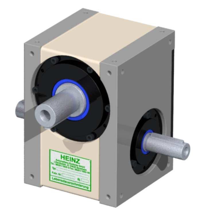
1 Operating Instructions Globoidal cam gear Type : Serial No. :
2 TABLE OF CONTENTS 1. General 1.1 Validity 1.2 Safety instructions 1.3 Shipment 1.4 Transport Regulations 1.5 Weights of gear types 2. Instructions for application of the gears 2.1 Installation position 2.2 Mounting of the gear 2.3 Gear operation 3. Start up 3.1 Gear function 3.2 Oil level 3.3 Interruption operation 3.4 Important instructions 4. Maintenance Instructions 4.1 General remark 4.2 Drive 4.3 Motor brake 4.4 Gear 5. Inspection instructions 5.1 Inspection cycle Hour-Service 6. Spare part installation 6.1 Remark 6.2 Globoidal mechanism Replacing cam followers (globoidal cam stays built in) Replacing turret (globoidal cam stays built in) Replacing globoidal cam (turret stays built in) Replacing mechanism completely 6.3 Tapered roller bearings 6.4 Spare and wearing parts 6.5 Spare part drawing 7. Final remark BWV_H(T)SG_E 2 / 20
3 1. General 1.1 Scope of this Manual This Operating Manual applies to a H(T)SG Globoidal Cam Indexing Gear Unit Anyone at the user's premises who sets up, puts into service, operates, maintains or repairs this Indexer must read the Operating Manual and observe its instructions. Keep this Operating Manual for reference at a safe and easily accessible location. Make sure that you are familiar with the safety instructions first. In this manual, the Cylindrical Cam Indexing Gear Unit is referred to as Indexer. Each Indexer is designed and built according to the state-of-the-art and complies with generally accepted safety rules. The Indexers are designed exclusively for indexed movements of a payload that does not endanger people, equipment or the environment while moving. These Indexers must only be used within the scope of this Operating Manual or according to the specifications agreed to in the sales documents. Any other use or any use exceeding these specifications, such as higher rotational speeds and/or higher loads or other mounting positions, do not comply with the Indexers' intended use. The manufacturer cannot be held liable for any damage resulting from such a use. This risk is born solely by the user. Intended use includes reading the operating and maintenance instructions and complying with the servicing and maintenance requirements. Only qualified professionals who understand the functionality of the Indexers are permitted to carry out maintenance work. BWV_H(T)SG_E 3 / 20
4 1.2 Safety Notes Before putting the Indexer into service, read the operating and maintenance instructions carefully. The Indexer complies with generally accepted safety rules. When installing the Indexer into a machine or plant, machine or plant attachments such as levers, toothed gear wheels with chains or similar can cause severe injuries to or death of the user or bystanders. Indexers must not be put into service, if the machine or plant in its entirety does not comply with the machine directive 2006/42/EC. Output shaft or flange with high torque! Do not reach into the operating range of the output shaft and its attachments! Crushing hazard by attachments mounted on the output shaft. Do not reach into the operating range of the output shaft and its attachments! For such a case, the user must implement all necessary protective measures on site. To protect operators from injuries that can be caused by the Indexer, install protective grating, covers or light curtains suitably. Always adhere to the relevant regulations for prevention of accidents as well as generally accepted health and safety regulations. Improper modifications and the use of replacement parts and additional equipment not recommended by the manufacturer can result in injuries to personnel or damage to property. Before starting any maintenance work, make sure that the Indexer is locked out and cannot be started. Any work on the Indexer requires specific technical knowledge. Preferably have HEINZ technicians or specifically trained professionals carry out this work. You cannot turn Indexers manually into one of their end positions. If position indexing is required, carry out this action by moving the input shaft only. BWV_H(T)SG_E 4 / 20
5 The Indexers are designed exclusively for indexing a payload that cannot endanger persons, equipment or the environment while moving. The Indexers must only be used within the scope of this Operating Manual and according to the specifications agreed to within the sales documents. Any other use or any use exceeding these specifications does not comply with the Indexers' intended use and voids any warranty by the manufacturer. When the Indexer is completed with an electric motor, this motor must be protected against overload. Before putting the Indexer into service, always replace the plug at the oil inlet with a vent plug. 1.3 Shipping Each Indexer is checked thoroughly and packaged properly before shipment. After unpacking the Indexer upon receipt at its destination, please inspect the Indexer for any damage sustained during transport. Should you note discrepancies, please report these to the carrier immediately. 1.4 Transport Instructions To move the Indexers, only use handling equipment approved to carry their weight. For weight specifications, refer to section 1.5. We have provided mounting holes for lifting screws. Attach suspension ropes or chains only to these lifting screws. To determine the weight of Indexers, refer to section 1.5 and the respective Indexer-type tables. BWV_H(T)SG_E 5 / 20
6 1.5 Indexer Weights Basic series Gear type Housing Weight [kg] modified series Gear type Housing Weight [kg] H(T)SG 63 GG 20 HSG 54 GG 8,5 H(T)SG 80 GG 28 HSG 80 E GG 28 H(T)SG 110 GG 57 HSG 80 M GG 27 H(T)SG 140 GG 116 H(T)SG 82 GG 27,5 H(T)SG 180 GG 200 HSG 100 GG 55,5 H(T)SG 200 GG 345 H(T)SG 108 GG 52 H(T)SG 254 GG 400 H(T)SG 108 M GG 52 HSG 125 GG 95 HTSG 140 M GG 95 HTSG 152 GG 132 H(T)SG 160 GG 145 H(T)SG 171 GG 190 H(T)SG 178 GG 190 H(T)SG 220 GG 350 HSG 250 GG 665 BWV_H(T)SG_E 6 / 20
7 2. Information on the Use of the Indexers 2.1 Mounting Position The universal design of these Indexers allows for virtually any mounting position on a machine or plant. When ordering an Indexer, please state mounting position, location of mounting holes and, if necessary, location of oil holes. The specified mounting position is crucial for proper lubrication of the Indexer components. Do not change this position in the machine or plant. 2.2 Indexer Installation The output shaft or flange and the input shaft are subjected to variable torques as a result of the Indexer's working principle. Therefore: - Always install the Indexers on a stable machined base. - Always secure the mounting bolts and fix the assembly additionally with dowel pins, if possible. - Always connect the Indexer to the driven payload directly, backlash-free and torsionally rigid. This also applies to the Indexer input shaft. 2.3 Indexer Operation When operating the Indexer, always observe the following instructions: Elasticity and play in the driven masses can result in vibration excitation and must be avoided. Any overload protection should be mounted to the output flange, if possible. BWV_H(T)SG_E 7 / 20
8 3. Putting into Service 3.1 How the Indexer Works The Indexer is a compact, robust unit that uses exactly calculated cams to transform a constant input speed into a predefined optimum output movement that is smooth and intermittent. The cam rollers running in the cam followers are precision guided along the cam by the hardened and polished cam track. This cam track has various leads and is divided into a dwell angle range and an indexing angle range. When rotating the cam, the cam track and the cam rollers generate a predefined smooth movement of the output shaft. As the cam is usually shaped symmetrically, rotations to the left and to the right are equally possible. The dwell angle range has a lead of zero. This causes a precisely defined self-locking positioning of the output shaft through the cam rollers without an additional locking device. When using a brake motor, the exact positioning of the output shaft is determined by the position of the cam rollers in the dwell angle range and not by the motor braking accuracy. The full dwell angle range is available for braking (refer to 3.3). 3.2 Oil Level Before putting the Indexer into service, always check the oil level. The oil level is sufficient if oil is visible in the sight glass. The following table lists the average filling quantity. Basic series Gear type An insufficient oil level adversely affects the functioning and service life of the Indexers. Oil qty. [ L ] modified series Gear type Oil qty. [ L ] Gear type Oil qty. [ L ] H(T)SG 63 0,40 HSG 54 0,20 HTSG 140 M 3,50 H(T)SG 8O 0,75 HSG 80 E 0,75 HTSG 152 2,30 H(T)SG 110 1,80 HSG 80 M 0,60 H(T)SG 160 6,80 H(T)SG 140 3,30 H(T)SG 82 0,75 H(T)SG 171 5,5 H(T)SG 180 7,50 HSG 100 1,50 H(T)SG 178 7,10 H(T)SG ,5 H(T)SG 108 1,60 H(T)SG ,5 H(T)SG ,0 H(T)SG 108 M 1,50 HSG ,0 HSG 125 3,80 H(T)SG 133 4,00 BWV_H(T)SG_E 8 / 20
9 3.3 Intermittent Service If the dwell angle range of the cam is not sufficient for a production-related standstill, you can extend the hold time using a brake motor. Braking is triggered by a limit switch activated by a cam connected to the input shaft. When putting the Indexer into service and during operation, make sure that after a braking action, the keyway of the input shaft always points to the casing side 6 and to the rotary axis of the output flange. In case of double indexing, this position can also be shifted by 180. The cam rollers must be in the middle of the dwell angle range of the respective cam. For Indexers with an additional index hand, this index hand must be within the middle range of the marking label after braking. 3.4 Important Information For input drives with two rotational speeds, normal operation is always at the higher speed (fast traverse speed). Only use the lower speed (creep speed) for setting up equipment or following an Emergency Stop to return to the dwell angle range.. Do not activate creep speed for automatic operation while in the movement phase. For controls that only enable switching to fast traverse speed via creep speed, this switch must take place within the dwell angle range, i.e. only within the marking label range or when the output shaft is at standstill. If these warnings are disregarded, any damage caused will not be covered by the warranty of the manufacturer. BWV_H(T)SG_E 9 / 20
10 4. Maintenance Instructions 4.1 General Information In case of queries or when ordering replacements parts, please indicate Indexer type and serial number. 4.2 Input Drive For maintenance work on Indexer brake motor or other input drives, refer to the manufacturer's maintenance instructions provided. 4.3 Engine Brake Due to wear and tear of the motor brake, we recommend that you check the stopping action in the dwell angle range regularly as described in 3.3. Adjust or replace the brake as necessary. BWV_H(T)SG_E 10 / 20
11 4.4 Lubrication of Indexer Oil Lubrication In Standard the gear unit is delivered with the synthetic lubricating oil Klübersynth GHE It is lubricated for life, i.e. no oil changes are necessary at all. The oil level should be checked at regular intervals. Sufficient oil is present if when the gear unit is stationary the oil can be seen in the sightglass The lubrication of the cam rollers and the came is thus guaranteed For rotating speed < 150 rpm For rotating speed > 150 rpm Klübersynth GHE Klübersynth GHE Mobil Glygoyle HE 460 (ISO V6 460) Mobil Glygoyle 22 (ISO V6 150) Shell Omala S4 WE 460 Shell Omala S4 WE 150 Warning: Never mix different oil sorts! Only top up with the lubricant described above! If used for the food industry, the gear unit is delivered with NSF H1 registered, conform to FDA 21 CFR oil "Klübersynth UH " It is lubricated for life, i.e. no oil changes are necessary at all. The oil level should be checked at regular intervals. Sufficient oil is present if when the gear unit is stationary the oil can be seen in the sightglass The lubrication of the cam rollers and the came is thus guaranteed For rotating speed < 150 rpm For rotating speed > 150 rpm Klübersynth UH Klübersynth UH Warning: Never mix different oil sorts! Only top up with the lubricant described above! Grease Lubrication It is lubricated for life, i.e. no grease are necessary at all. The grease level should be checked at regular intervals. Normal Grease Lubrication NSF H1 registered, conform to FDA 21 CFR Castrol Olit 00 Cassida RLS 00 Microlube GB 00 Klübersynth UH Warning: Never mix different oil sorts! Only top up with the lubricant described above! BWV_H(T)SG_E 11 / 20
12 5. Information on Preventative Maintenance 5.1 Preventative Maintenance Schedule To ensure mechanical reliability, we recommend the following checks at regular intervals but at least every 8000 hours of operation: 1. Check oil level and top-up as necessary 2. Check casing and bearing covers for overheating, discolouring and unusual noises. 3. Check Indexer for overheating, unusual noises, functional reliability and play. 4. Check functional reliability of all seals Do the following, if the condition of the items described does not correspond to their original state any longer: 1. Top-up lubricant (refer to sections 3.2 and 4.4) 2. Replace roller bearing at input and output shaft (refer to section 6.2) 3. Replace cam rollers (refer to section 6.2) 4. Replace seals (refer to section 6.2) After approximately 30,000 hours of operation, we recommend that you replace all roller bearings and cam rollers. At the same time, also replace all seals to avoid any damage to the Indexer caused by a possible loss of lubricant. BWV_H(T)SG_E 12 / 20
13 6. Replacement Parts Assembly Before starting any disassembly works, carefully read the entire text. Always clean and check all components for perfect condition before installing them. For disassembly and reassembly of component parts, refer to the replacement parts list. When using solvents, make sure that they do not get into contact with O-rings or sealing rings of the shafts. In case of queries or when ordering replacement parts, please have type number and serial number ready for faster processing. Any repair work requires specific technical knowledge. Preferably have technicians of HEINZ AUTOMATIONS-SYSTEME GmbH carry out this work. 6.1 Tapered Roller Bearings / Deep Groove Ball Bearings When installing tapered roller bearings and deep groove ball bearings, make sure to adjust the bearings free from backlash. You can correct a bearing clearance, which is too large or too small, by adapting the bearing cover or the eccentric cover. Then check the unit for smooth running by turning the input shaft. Readjust, if necessary. BWV_H(T)SG_E 13 / 20
14 6.2 Globoidal mechanism The mechanism is a unit consisting of globoidal cam, cam followers and turret. Due to a possible wear of the cam followers or the globoidal cam, it may be necessary to replace the following parts: Cam followers Turret Globoidal cam Complete mechanism Replacing cam followers (globoidal cam stays built in) Drain oil Move input shaft into dwell angle area Unscrew end cap of output shaft Lift output shaft out of globoidal housing Unscrew stud bolts off turret (are glued in) and remove cam followers Check shaft bore of cam followers in the turret if they are damaged and possibly widened In case of defective bores: see In case of perfect condition of bores, push in new cam followers into turret In case of cam followers without key way, bore with core hole drill a centralisation in every cam followers shaft. The depth of centralisation depends on the centralisation point of the stud bolts according to DIN914 (German Industrial Standard) Secure cam followers with stud bolts (glue thread in) Check globoidal cam and replace by a new one if necessary (see chapter 6.2.3) Put output shaft with turret back into housing (observe the position of the shaft key groove of the output shaft) Apply appropriate permanently elastic sealing material upon cleaned sealing surface and install end cap Move input shaft and check regular movement of mechanism Fill in oil Replacing turret ( globoidal cam stays built in) In the case of a defective cam followers shaft bore remove (smaller) tapered roller bearing Remove stud bolts off turret and disassemble turret off output shaft Screw tight new turret with installed cam followers again and put in new studs Heat tapered roller bearing slightly (max. 80 C) and push over output shaft Replace defective bearings with new ones! Put output shaft with turret back into housing (observe position of shaft key groove of output shaft) Proceed with assembly as describe in chapter BWV_H(T)SG_E 14 / 20
15 6.2.3 Replacing globoidal cam (turret stays built in) Drain oil Move input shaft into dwell angle area Screw off housing cover Release safety catch of securing steel sheets and unscrew lock nut Unscrew both eccentric covers Push inner ring of tapered roller bearing (maximum 3 mm less than width of lock nut) off input shaft by using lock nuts Pull off tapered roller bearing by using an extractor Remove lock nut and securing steel sheets Drive input shaft out of globoidal cam without using too much power on the cam followers Take old globoidal cam out of housing Put new globoidal cam with dwell angle area between two cam followers (Observe position of shaft key groove of output shaft) Drive input shaft into cam without using too much power on the cam followers Screw new securing steel sheets and new lock nuts on input shaft Heat tapered roller bearing (max. 80 C) and push over input shaft Replace defective bearings with new ones! Screw off eccentric cover. While doing so, make sure no preloading is produced between cam follower and cam, possibly move cam by using the lock nut or turn eccentric cover Check preloading of tapered roller bearing in dwell angle area, possibly by adjusting the eccentric cover Adjust mechanism without backlash by turning eccentric cover and/or by moving the cam The height tolerance of the input shaft pivot may not exceed maximum 0,02 mm on the total length of the pivot. An even contact reflection of the cam follower and globoidal cam is absolutely required - check with inking past! Screw lock nuts tightly and secure Screw eccentric cover tightly Turn input shaft with hand and check its even running, possibly repeat adjustment Cover all openings Put pins into eccentric cover (possibly earmark pin holes on same pc-diameter with same depth of bores, remove chips) Screw off eccentric cover, seal, bring into line above pin bore, tighten slightly, push pins and screw tightly Install new oil seals seal housing cover and screw tightly Fill in oil Replacing mechanism completely Please refer to chapter to for the instructions for disassembling and installation of the turret. BWV_H(T)SG_E 15 / 20
16 6.3 Tapered roller bearing When installing new tapered roller bearings, it has to be observed that the bearings are adjusted free of play. If the backlash is to high or too low, this can be corrected by adjusting the housing cover or eccentric cover. Afterwards check the correct running of the mechanism by turning the input shaft, readjust if necessary. 6.4 Spare and wearing parts 1. Mechanism 1.1 Globoidal cam 1.2 Turret 1.3 Cam followers 2. Bearing set 2.1 Tapered roller bearing output Tapered roller bearing output Tapered roller bearing output 3. Sealing set 3.1 Oil seal output 3.2 Oil seal input 3.3 O-Ring output 3.4 O-Ring input 4. Input shaft 5. Output shaft BWV_H(T)SG_E 16 / 20
17 6.5 Spare part drawing (HSG / HTSG) HSG BWV_H(T)SG_E 17 / 20
18 HTSG BWV_H(T)SG_E 18 / 20
19 7. Final remark All repair work requires a certain amount of experience and should therefore be carried out by HEINZ fitters. Address of HEINZ: HEINZ AUTOMATIONS-SYSTEME GmbH HEINZ GmbH Lilienthalstr. 21 Kochhorstweg 33 D Bensheim D Elsterwerda Tel.: 0049 (0)6251 / Fax: 0049 (0)6251 / mail@heinz-automation.de BWV_H(T)SG_E 19 / 20


20 Lilienthalstrasse 21 - D Bensheim Telefon +49(0)6251/ Fax +49(0)6251/ BWV_H(T)SG_E 20 / 20
Operating Instructions. Parallel shaft cam gear
 Operating Instructions Parallel shaft cam gear Type : Serial No. : C O N T E N T S 1. General 1.1 Validity 1.2 Safety instructions 1.3 Shipment 1.4 Transport Regulations 1.5 Weights of gear types 2. Instructions
Instructions for Use Plain Trolley ULK Geared Trolley UHK
 Instructions for Use Plain Trolley Geared Trolley Item no. Load-carrying capacity (payload) Weight Trolley widths *special trolley widths* Device dimensions mm H / W / D Minimum curve radius mm -005 0,5
Assembly and Maintenance Manual Type ASNU
 Assembly and Maintenance Manual Type ASNU Hatschekstr.36 69126 Heidelberg Germany Tel +49(0)6221 30470 Fax +49(0)6221 304731 info@stieber.de www.stieber.de Date of issue: 30.05.2018 GB Revision: 0 U:\EngUsers\!ProduktDoku\1AAA_Einbauerklaerung_Wartungsanleitung_Konformitaetserklaerung\1AAA_Wartungsanleitungen\Orginal_Worddatei\_ASNU.docx
Operating and Maintenance Manual. for. HADEF overhead crane. as jointed crane TA
 5.52.714.00.1.0 Edition 03.2004 GB Operating and Maintenance Manual for HADEF overhead crane as jointed crane TA Subject to changes. 1 HADEF Table of Contents 1 General Page 3 2 Product description Page
Assembly and Maintenance Manual Type RSBW
 Assembly and Maintenance Manual Type RSBW Hatschekstr. 36 69126 Heidelberg Germany Tel +49(0)6221 30470 Tel +49(0)6221 304731 info@stieber.de www.stieber.de Stieber Clutch Date of issue: 16/03/2017 GB
Assembly and Maintenance Manual Type AS
 Assembly and Maintenance Manual Type AS Hatschekstr.36 69126 Heidelberg Germany Tel +49(0)6221 30470 Fax +49(0)6221 304731 info@stieber.de www.stieber.de Date of issue: 30.05.2018 GB Revision: 0 U:\EngUsers\!ProduktDoku\1AAA_Einbauerklaerung_Wartungsanleitung_Konformitaetserklaerung\1AAA_Wartungsanleitungen\Orginal_Worddatei\_AS.docx
Translation of the Original operating instructions Lifting device Z 70 /...
 Translation of the Original operating instructions Lifting device Z 70 /... Content 1. Lifting device / Correct use according to regulations 2. Basic principles 3. General information 4. Special remarks
Drehen. Rotating. Rotating
 Drehen Drehen is an established process used in automated production lines. To be exact, it involves incremental rotating and positioning in manufacturing installations. Typical applications include feeding
HP High-Performance Gear Units with <2' Adjustable Backlash
 Page HP High-Performance Gear Units with
Tension Meter. Edition FT 03.E. FT Series. Instruction Manual. Valid as of: Please keep the manual for future reference!
 Tension Meter FT Series S C H M I D T c o n t r o l i n s t r u m e n t s Edition FT 03.E Model FT Instruction Manual Valid as of: 01.09.2011 Please keep the manual for future reference! Contents 1 Warranty
OPERATING INSTRUCTIONS (Translation) Hoisting crane
 Hoisting crane") 1. User Groups Duties Operator Operation, visual inspection Specialist personnel OPERATING INSTRUCTIONS (Translation) Hoisting crane Type 4781.0,25 Assembly, disassembly, repair, maintenance Tests GB Qualifications
1. User Groups Duties Operator Operation, visual inspection Specialist personnel OPERATING INSTRUCTIONS (Translation) Hoisting crane Type 4781.0,25 Assembly, disassembly, repair, maintenance Tests GB Qualifications
Product Information Overspeed governor GB 260
 Product Information GB 260 Copyright as per DIN ISO 16016. Manufactured under licence of C. Haushahn GmbH & Co. I Subject to modification. Published by SLC Sautter Lift Components GmbH & Co. KG Borsigstrasse
Lifting device for standard removable versions
 Operating manual Lifting device for standard removable versions Type 1889 haacon hilft heben haacon hebetechnik gmbh Josef-Haamann-Str. 6 D-97896 Freudenberg/Main Tel: +49 (0) 93 75/84-0 Fax: +49 (0) 93
Drive Unit e-drive1. Installation instructions 04/2014. English translation of the original German installation instructions
 Drive Unit e-drive1 Installation instructions 04/2014 English translation of the original German installation instructions Contents Foreword... 3 Availability... 3 Structural features in the text... 3
Electropneumatic Converters i/p Converters Type 6111 Mounting and Operating Instructions EB 6111 EN
 Electropneumatic Converters i/p Converters Type 6111 Fig. 1 Type 6111 in standard version Fig. Type 6111 mounted on a supply air manifold Fig. 3 Type 6111 in field enclosure Mounting and Operating Instructions
Single-Position Detent Clutch DC Series. (i) MTY (81) MEX (55) QRO (442)
 MTY (81) MEX (55) QRO (442)") Single-Position Detent Clutch DC Series (i) FORM NO. L-2017-A-001 In accordance with Nexen s established policy of constant product improvement, the specifications contained in this manual are subject
Single-Position Detent Clutch DC Series (i) FORM NO. L-2017-A-001 In accordance with Nexen s established policy of constant product improvement, the specifications contained in this manual are subject
Turbocharger / VTR..0, VTR..1 Original assembly instructions English
 Assembly Instructions Turbocharger / VTR..0, VTR..1 Original assembly instructions English This document is valid for the VTR..0/..1 series: VTR160, VTR200, VTR250, VTR320, VTR400 VTR161, VTR201, VTR251,
1000-LB. MOTORCYCLE LIFT TABLE OWNER S MANUAL
 1000-LB. MOTORCYCLE LIFT TABLE OWNER S MANUAL WARNING: Read carefully and understand all ASSEMBLY AND OPERATION INSTRUCTIONS before operating. Failure to follow the safety rules and other basic safety
OPERATING INSTRUCTIONS INDEPENDENT WHEEL SUSPENSION RL 75 E/EC FRONT AXLE/TAG AXLE RL 75 A
 INDEPENDENT WHEEL SUSPENSION RL 75 E/EC FRONT AXLE/TAG AXLE RL 75 A 587.97.90 en Preface This documentation has been developed for specialized staff trained by ZF Friedrichshafen AG for repair and maintenance
A408 GB. Pneumatic oil and diesel pumps 1:1
 03 594 A408 GB Pneumatic oil and diesel pumps 1:1 G Operating instructions for Pneumatic oil and diesel pump 1:1 Contents 1. General details 2 1.1 Intended use 2 1.2 Design and functional description 2
Operating Instructions for Roll-Up Door Operators / MDF
 Operating Instructions for Roll-Up Door Operators / MDF GB Roll-Up Door Operator / MDF / Rev. 0.0 1 1. Contents 3. General safety instructions 1. Contents 2 2. Key to symbols 2 3. General safety instructions
VBK 2596/12E/RSF. Thickness and Width Gauge for Strip and Profile. Operating- & Service Instructions. (with lateral guide rollers)
") Thickness and Width Gauge for Strip and Profile (with lateral guide rollers) VBK 2596/12E/RSF Operating- & Service Instructions erstellt am 5.2.1998 freigegeben am Bemerkungen Rev.01 Seiten:16 Name: Rietdorf
Thickness and Width Gauge for Strip and Profile (with lateral guide rollers) VBK 2596/12E/RSF Operating- & Service Instructions erstellt am 5.2.1998 freigegeben am Bemerkungen Rev.01 Seiten:16 Name: Rietdorf
Roller chain idler sprocket units Idler pulley units
 Roller chain idler sprocket units Idler pulley units Roller chain idler sprocket units, idler pulley units Page Product overview Roller chain idler sprocket units, idler pulley units... 334 Design and
RIGHT ANGLE DRIVES TG Series
 RIGHT ANGLE DRIVES TG Series Right Angle Fixed Index Drives TG Series The rotary index table transforms a constant input drive motion into an intermittent output drive motion. The intermittent drive motion
Operating Instructions
 Operating Instructions Table of contents Table of contents... 1 1. Declaration... 1 2. Warranty and liability... 2 3. Gear description... 2 4. Gear types... 2 5. Safety... 3 5.1 General safety information...
Maintenance Instructions
 General Note These instructions contain information common to more than one model of Bevel Gear Drive. To simplify reading, similar models have been grouped as follows: GROUP 1 Models 11, 0, 1,, (illustrated),,
BA EN.=A. Ä.=A.ä. Operating Instructions. Gearbox. Type 12. / 52.
 BA 12.0028 EN.=A. Ä.=A.ä Operating Instructions Gearbox Type 12. / 52. Product key Gearboxes 1 2... Product group Product family Gearbox size Design Geared motors 1 2... Product group Product family Gearbox
Operating manual Separator
 Operating manual Separator Sheet no. AS/4.1.141.1.1 issue 20.08.2014 Contents Section Title Page 0 Introduction... 1 1 Intended use......1 2 Marking of the fitting... 1 3 Safety instructions... 2 4 Transport
Operating Instructions
 BA 12.0028 450 298 EN Operating Instructions K12.0549 Typ Gearboxes 12.jjj 52.jjj Product key Gearboxes ➀ ➁ ➂ ➃ Product group Product family Gearbox size Design ➀ ➁ ➂ ➃ 12. 602. 20. 11 Geared motors ➀
2000-LB. ENGINE STAND
 2000-LB. ENGINE STAND WARNING: Read carefully and understand all ASSEMBLY AND OPERATION INSTRUCTIONS before operating. Failure to follow the safety rules and other basic safety precautions may result in
Operating Instructions for Elevator Buffers type LP
 Operating Instructions for Elevator Buffers type LP 1 Scope of application The Elevator Buffer type LP is an energy dissipation type buffer according to EN 81-1/2, EN 81-20, EN 81-50 5.5 and therefore
Mounting and Operating Instructions EB 8135/8136 EN. Series V2001 Valves Type 3535 Three-way Valve for Heat Transfer Oil
 Series V2001 Valves Type 3535 Three-way Valve for Heat Transfer Oil Type 3535 Three-way Valve with bellows seal and rod-type yoke (partial view) Mounting and Operating Instructions EB 8135/8136 EN Edition
EU DECLARATION CONFORMANCE
 LOGIFLEX ELF / ELFS EU DECLARATION CONFORMANCE Manufacturer: Logitrans A/S Hillerupvej 35 DK-6760 Ribe Denmark It is hereby declared that: Machine: Productgroup: Logiflex Type: ELF/ELFS Year of manufacture/
The EFL 2000/1 & 2 User Guide Test Sieve Shaker. Contents
 The EFL 2000/1 & 2 User Guide Test Sieve Shaker ISSUE 04-02 Contents Description Page 1 Setting Up: 2-8 Unpacking 2 Assembly 3 Clamping Assembly 4 Electrical Connections 5 Sieve Stacking 6 8 Operating
[1] [2] [1-1] [1-2] [1-7] [1-6] [1-3] [1-4] [1-5] [2-1] [2-2] [2-3] [2-7] [2-6] [2-4] [2-5]
![[1] [2] [1-1] [1-2] [1-7] [1-6] [1-3] [1-4] [1-5] [2-1] [2-2] [2-3] [2-7] [2-6] [2-4] [2-5]](/thumbs/76/73505937.jpg "[1] [2] [1-1] [1-2] [1-7] [1-6] [1-3] [1-4] [1-5] [2-1] [2-2] [2-3] [2-7] [2-6] [2-4] [2-5]") SATA dry jet 2 Betriebsanleitung Упътване за работа 使用说明书 Návod k použití Betjeningsvejledning Kasutusjuhend Operating Instructions Instrucciones de servicio Käyttöohje Mode d'emploi Οδηγίες λειτουργίας
SATA dry jet 2 Betriebsanleitung Упътване за работа 使用说明书 Návod k použití Betjeningsvejledning Kasutusjuhend Operating Instructions Instrucciones de servicio Käyttöohje Mode d'emploi Οδηγίες λειτουργίας
BR 31a Rack-and-pinion Actuator,
 Operating, assembly and maintenance instructions BR 31a Rack-and-pinion Actuator, SRP and DAP 1. General These instructions are intended to support the user in the assembly, maintenance, and repair of
3000-Lb. Vehicle Positioning Jacks. Owner s Manual
 3000-Lb. Vehicle Positioning Jacks Owner s Manual WARNING: Read carefully and understand all ASSEMBLY AND OPERATION INSTRUCTIONS before operating. Failure to follow the safety rules and other basic safety
English. Instruction and operation manual S 212. Dew point sensor
 English Instruction and operation manual S 212 Dew point sensor Dear Customer, thank you for choosing our product. The operating instructions must be read in full and carefully observed before starting
O P E R A T I N G M A N U A L
 O P E R A T I N G M A N U A L - Original - A 5615-2 / Rolltrailer 60 100t Page 1 / 18 Product Seacom Rolltrailer RT 60 100t Serial no. A 5615-2 / 1-35 Customer Grimaldi - Italy Supplier Transport Systems
Instruction manual and installation guide Traction sheave brake TSB TSB
 Instruction manual and installation guide Traction sheave brake TSB 2000-1 TSB 2000-2 Content Traction sheave brake Page 1. Safety 2 1.1 Explanation of symbols 2 1.2. General safety instructions 3 2. Product
DODGE USAF 200/300 Direct Mount Pillow Block Bearings
 DODGE USAF 200/300 Direct Mount Pillow Block Bearings These instructions must be read thoroughly before installation or operation. This instruction manual was accurate at the time of printing. Please see
EC MACHINE DIRECTIVE COMPLIANCE DECLARATION
 EC MACHINE DIRECTIVE COMPLIANCE DECLARATION (DIRECTIVE 89/392 EEC, APPENDIX II, PART B) Manufacturer: FAAC S.p.A. Address: Via Benini, 1 40069 - Zola Predosa BOLOGNA - ITALY Hereby declares that: the 770
Mounting and Operating Instructions EB 8039 EN. Type 3351 Pneumatic On/off Valve. Type 3351 Pneumatic On/off Valve. Type 3351 Pneumatic On/off Valve
 Type 3351 Pneumatic On/off Valve Type 3351 Pneumatic On/off Valve Type 3351 Pneumatic On/off Valve Version with handwheel Mounting and Operating Instructions EB 8039 EN Edition May 2016 Definition of signal
Axial Piston Fixed Pump A17FNO Series 10
 Axial Piston Fixed Pump A17FNO Series 10 RE 91510 Issue: 06.2012 Replaces: 03.2010 Size 125 Nominal pressure 250 bar Maximum pressure 300 bar For commercial vehicles Open circuit Features Fixed pump with
Servo-conventional milling machine
 Universal Milling Machine Servo-conventional milling machine Control developed and built in Germany Positioning control for traveling pre-selected paths on all axes Constant cutting speed, whereby the
OVERLOAD CLUTCHES FOR INDEX DRIVES
 The Driving Force in Automation OVERLOAD CLUTCHES FOR INDEX DRIVES WARNING WARNING This is a controlled document. It is your responsibility to deliver this information to the end user of the CAMCO indexer.
Adjustable Speaker Mount GRAVIS 8
 Adjustable Speaker Mount GRAVIS 8 User's Manual Translation of the original instructions Important Information, Please Read Before Use! KLING & FREITAG GmbH Junkersstraße 14 D-30179 Hannover TEL +49 (0)
Adjustable Speaker Mount GRAVIS 12
 Adjustable Speaker Mount GRAVIS 12 User's Manual Translation of the original instructions Version 3.3 Released: 19.01.2017 Important Information, Please Read Before Use! KLING & FREITAG GmbH Junkersstraße
Hot Pressing Device PQ-58
 Habasit AG Postfach, CH-4153 Reinach-Basel Phone ++41 61 715 15 15 Fax ++41 61 715 15 55 Operating Instructions 36007 Author: Gul/Ni/Nyk Page 1 of 20 Replaces: Edition 03/0102 Hot Pressing Device The is
Assembly and maintenance manual Type FSO, FSO-GR, FS, HPI
 Type FSO, FSO-GR, FS, HPI Hatschekstr.36 69126 Heidelberg Deutschland Tel +49(0)6221 30470 Fax +49(0)6221 304731 info@stieber.de www.stieber.de Date of issue: 23.08.2018 GB Revision: 0 U:\EngUsers\!ProduktDoku\1AAA_Einbauerklaerung_Wartungsanleitung_Konformitaetserklaerung\1AAA_Wartungsanleitungen\Orginal_Worddatei\M1124E_0_FSO_FSO-GR_FS_HPI.docx
Service - Safety Manual
 Service - Safety Manual Mounting and maintenance instructions Linear Units LT50 series Code Unit Serial number Date by Linear Units LT50 series Table of contents 1 Safety 3 1.1 Significance of the manual
The chronograph calibres CHRO PC 17 jewels CHRO C12 PC 17 jewels CHRO C12 PC AMPM GMT 17 jewels CHRO PC CAL 17 jewels
 Technical guide The chronograph calibres 860 27 CHRO PC 17 jewels 861 27 CHRO C12 PC 17 jewels 910 27 CHRO C12 PC AMPM GMT 17 jewels 930 27 CHRO PC CAL 17 jewels o 27.00 mm / Power-reserve Jewel number
Operating Instruction
 Operating Instruction Drive element LEWA - ecosmart type LCA with manual stroke adjustment, motor mounted vertically Table of contents 1 General information / safety 1.1 Important preliminary information
Operating Instructions ROCO Butterfly Valve with SKG Slider-crank Mechanism, with Electric Multi-turn Actuator
 Operating Instructions ROCO Butterfly Valve with SKG Slider-crank Mechanism, with Electric Multi-turn Actuator 1 Product and Performance Description 2 Design Features of ROCO Butterfly Valve 3 Installation
1000-LB. ENGINE STAND
 1000-LB. ENGINE STAND WARNING: Read carefully and understand all ASSEMBLY AND OPERATION INSTRUCTIONS before operating. Failure to follow the safety rules and other basic safety precautions may result in
Mounting and Operating Instructions EB 3913 EN. Electropneumatic Converters i/p Converter Type
 Electropneumatic Converters i/p Converter Type 3913-0001 Fig. 1 Type 3913-0001 Electropneumatic Converter with pressure gauge and bracket Mounting and Operating Instructions EB 3913 EN Edition August 2011
Bellows Page 415. Overview Universal Joints. Single Universal Joints. Speeds* max. min
 Overview Universal Joints Single Universal Joints Type UKM GF KE WEL RW AR WE WEN WER Material Plastic Plastic Stainless STAINLESS Bearings Bores mm 2-10 8-16 0-40 6-30 6-45, hardened 6-30, hardened 6-40
Installation and Operating Instructions for EAS -NC clutch Type 45_. _. _ Sizes 02 and 03
 Table of contents: Please read and observe this Operating Instruction carefully! A possible malfunction or failure of the clutch and any damage may be caused by not observing it. Page 1: - Table of contents
D58 Series Brake Instructions
 D58 Series Brake Instructions 4740 W. Electric Avenue Milwaukee, WI 53219 414/672-7830 FAX 414/672-5354 www. dingsbrakes.com Safety information 2 Safety information 2.1 Persons responsible for the safety
Technical Description Edition 2007 Mounting, maintenance and repair of propshafts with flanged universal joints
 Technical Description Edition 2007 Mounting, maintenance and repair of propshafts with flanged universal joints 1. Recommendations Assembly, disassembly, maintenance and repair of propshafts should be
Rotary feed-through DDF-S/-KS
 Translation of the Original Operating Manual Rotary feed-through DDF-S/-KS Assembly and Operating Manual Superior Clamping and Gripping Imprint Imprint Copyright: This manual remains the copyrighted property
Hand Pallet Truck NC. Operation Manual
 Hand Pallet Truck -------NC Operation Manual Operation Manual 1 Application Range This product is suitable for using in rated load of up to 5500lbs. This PL5500HD is the perfect jack for handling palletized
Type 3761 Pneumatic or Electropneumatic Positioner for Rotary Actuators. Fig. 1 Type 3761 Positioner. Mounting and Operating Instructions EB 8386 EN
 Type 3761 Pneumatic or Electropneumatic Positioner for Rotary Actuators Fig. 1 Type 3761 Positioner Mounting and Operating Instructions EB 8386 EN Edition July 2007 Contents Contents Page 1 Design and
Instruction Manual. Sewage lifting station compli 300
 Instruction Manual Sewage lifting station compli 300 Safety instructions Areas of application Electrical connection Installation Servicing Technical data Appendix JUNG PUMPEN GmbH Industriestr. 4-6 33803
Support T10552 T10595 T40386
 T10552 T10595 T40386 en-gb 7 T10552 T10595... 1 General Information Product name: Product type: Product number: Weight: Max. load capacity: Static test coefficient: 3.0 Intended Use: Load holding device
Installation and Operational Instructions for EAS - HTL housed overload clutch Sizes 01 3 Type 490._24.0
 Please read these Operational Instructions carefully and follow them accordingly! Ignoring these Instructions may lead to malfunctions or to clutch failure, resulting in damage to other parts. Contents:
ZERO-POINT CLAMPING SYSTEM
 simple. gripping. future. ZERO-POINT CLAMPING SYSTEM 22 Quick Point Grid Plates 3 Quick Point Plates 34 Quick Point Round Plates 39 Quick Point Adaptor Plates 4 Quick Point Clamping Studs 43 Quick Point
3-Pt. Quick Hitch. Owner s Manual
 3-Pt. Quick Hitch Owner s Manual WARNING: Read carefully and understand all ASSEMBLY AND OPERATION INSTRUCTIONS before operating. Failure to follow the safety rules and other basic safety precautions may
LUBRICATION, INSTALLATION, OPERATION & MAINTENANCE INSTRUCTIONS FOR STAINLESS STEEL CONE DRIVE SPEED REDUCERS
 LUBRICATION, INSTALLATION, OPERATION & MAINTENANCE INSTRUCTIONS FOR STAINLESS STEEL CONE DRIVE SPEED REDUCERS Cone Drive double-enveloping worm gear speed reducers are used throughout industry to provide
Mod: KLD6-12/35XLAS-N
 12/2011 Mod: KLD6-12/35XLAS-N Production code: 1914070 INSTRUCTION MANUAL LOGIC LINE PLUS HOOD Reseller Stamp for Warranty Dear customer, Above all, thank you for choosing our product and we would like
HST -LS Interlocking device (Translation of Original Manual)
") Installation and Operating Manual for Components HST -LS Interlocking device (Translation of Original Manual) HST-LS Ident.-No.: 10268 HST-LS Ident.-No.: 10269 HST-LS, pictured Ident-Nr. 10269 The image
Installation and Operating Manual for Components HST -LS Interlocking device (Translation of Original Manual) HST-LS Ident.-No.: 10268 HST-LS Ident.-No.: 10269 HST-LS, pictured Ident-Nr. 10269 The image
Storage, operating and maintenance instructions for AZ plug valves and Standard valves
 ARMATUREN Plug - Valves metallic with PTFE Sleeve 2-7 way Storage, operating and maintenance instructions for AZ plug valves and Standard valves Plug - Valves FEP/PFA - lined, 2-3 way Butterfly - Valves
MEYER-Rotating Fork Positioners are attachments used to transport loads and replace
 This MEYER-Attachment complies in every aspect to the EC-Safety Guidelines. The Certificate of Conformation / Declaration by the Manufacturer has been delivered with the attachment. The CE-Symbol can be
Compensation unit AGE-XY 50-80
 Translation of the origninal manual Compensation unit AGE-XY 50-80 Assembly and operating manual Superior Clamping and Gripping Imprint Imprint Copyright: This manual remains the copyrighted property of
Operating Instructions. TM Girder Clamps
 Operating Instructions TM Girder Clamps Original operating instructions in keeping with the EC Machinery Directive TM-BC-10 TM-BC-20 TM-BC-30 TM-BC-50 TM girder clamps meet requirements as per EU Machinery
FLENDER ZAPEX couplings. Type ZWT. Operating instructions BA 3505 EN 10/2011. FLENDER couplings
 FLENDER ZAPEX couplings Type ZWT Operating instructions FLENDER couplings FLENDER ZAPEX couplings Type ZWT Operating instructions Translation of the original operating instructions Technical data Notes
LINEAR MOTION CONTROL
 LINEAR MOTION CONTROL PRODUCTS User Manual Precision Roller Pinion System RPS 16 RPS20, RPS25, RPS32, RPS40 Premium and Standard Models DANGER Read this manual carefully before installation and operation.
Tension Meter. PT Series. Instruction Manual PT-100-L. Valid as of: Please keep the manual for future reference!
 Tension Meter S C H M I D T PT Series c o n t r o l i n s t r u m e n t s Edition PT 01.0.E Model PT-100 PT-100-L Instruction Manual Valid as of: 15.04.2011 Please keep the manual for future reference!
Operating Instructions for Paddle Flowswitch Model: PPS-...
 Operating Instructions for Paddle Flowswitch Model: PPS-... 1. Note Please read and take note of these operating instructions before unpacking and commissioning. The instruments may only be used, maintained
Bevel gearboxes. Catalogue
 Bevel gearboxes Catalogue INDEX Bevel gearbox description... page 2 Manufacturing features... page 2 Materials and components... page 4 Bevel gearbox selection... page 5 Thermal power limit... page 7
Amerigear SF Spindle
 Amerigear SF Spindle Installation and Maintenance Manual Form No. 381-SH, 4/01 Spindle Installation and Maintenance Manual TABLE OF CONTENTS SECTION TITLE PAGE 1 Introduction...: 3 2 General Information...:
Operating manual. Custom made gearboxes
 Operating manual Custom made gearboxes DSS-Nr. 100389549 DSS-Rev. 001 Datum 16.01.2018 Contents Contents 1 General information 3 1.1 Using the operating manual 3 1.2 Warnings in this operating manual 4
FLENDER COUPLINGS SIPEX. Operating Instructions 3800en Edition 10/2017 SNN, SGG, SGG-A, SHH, SKK, SII, SGS, SHH-W
 FLENDER COUPLINGS SIPEX Operating Instructions 3800en Edition 10/2017 SNN, SGG, SGG-A, SHH, SKK, SII, SGS, SHH-W 26.09.2017 09:25 V2.01 Introduction 1 Safety instructions 2 FLENDER COUPLINGS SIPEX 3800en
Crossed Roller Ways. Description of each series and Table of dimensions. Anti-Creep Cage Crossed Roller Way
 Crossed Roller Ways Description of each series and Table of dimensions Crossed Roller Way Page - to -7 Anti-Creep Cage Crossed Roller Way Page - to - Crossed Roller Way Unit Page - to - In the table of
Instruction and Installation Manual
 Instruction and Installation Manual ROSTA Tensioner Devices Tensioners Accessories -G -W -R Sprocket wheel N Chain rider P Oil resistant Up to + 120 C Reinforced Sprocket wheel set Chain rider set -I -F
SMB. Assembly and operating instructions Sprinkler measuring orifice SMB/SMB-OE. Sprinkler measuring orifice
 Assembly and operating instructions /-OE Fon: +49 2065 9609-0 Fax: +49 2065 9609-22 Internet: www.kt-web.de e-mail: info@kt-web.de 2 1. General...3 1.1 Exclusion of liability...3 2. Safety...4 2.1 General
INSTALLATION OPERATING SERVICE AND SAFETY INSTRUCTIONS
 MODEL GE 970 Boom Mounted Compactor / Driver GENPAC INSTALLATION OPERATING SERVICE AND SAFETY INSTRUCTIONS PARTS LIST 1.0 INTRODUCTION The Genpac GE-970 is a boom-mounted hydraulic vibrating plate compactor
Conveyor chain catalogue
 Conveyor chain catalogue www.renold.com Table of Contents Section - Conveyor Products and Dimensions Conveyor chain introduction....................................................................5-7 BS
Operating Instructions Thread Rolling Heads F 001, F 01, K 01-1
 Head in fixed application (for F and K types): The front part of the head is turned by using the handle (25) with the ball (23) (if used on automatics, closing is accomplished by using closing roller over
Timing-Belt Reverse Unit 8 80 R25 Notes on Use and Installation
 Timing-Belt Reverse Unit 8 80 R25 Notes on Use and Installation Content General General hazard warning 2 Appropriate use 3 Content Application 3 Technical Data/Scope of Supply 3 Application Options 4 Fitting
RADEX -N Composite Operating/Assembly instructions
 1 of 14 RADEX -N is a torsionally stiff flexible steel lamina coupling. It is able to compensate for shaft misalignment, for example caused by thermal expansion, etc. note ISO 101. Drawn: 0.05.15 Kb/Wig
BoWex FLE-PA. BoWex FLE-PAC. KTR-N Sheet: Edition: EN 1 of BoWex FLE-PA / FLE-PAC Operating/Assembly instructions
 1 of 17 is a torsionally rigid flange coupling. It is able to compensate for shaft misalignment, for example caused by manufacturing inaccuracies, thermal expansion, etc. BoWex FLE-PA BoWex FLE-PAC Drawn:
SA Series Robot Instruction Manual
 SA Series Robot Instruction Manual Product Series: Full range of SA series Publication Status: Standard Revision: A-0001 ADTECH (SHENZHEN) TECHNOLOGY CO., LTD. Copyright. All Rights Reserved. Without prior
Ball splines can be configured for an endless number of automated operations. Demystifying Ball Spline Specs
 Ball splines can be configured for an endless number of automated operations. Demystifying Ball Spline Specs Place a recirculating-ball bushing on a shaft and what do you get? Frictionless movement of
LOCKED SERIES. Machine Failures. General Information. set up. maintenance. reconditioning. repair 30.4%
 General Information LOCKED SERIES 2 Lowering machinery process costs is key in today s world. According to a recent study approximately a third of all machine stoppages result in unexpected damage and
Instruction Manual. Maximum Operating Pressure 700 bar
 Remote Hydraulic Cutter Model HC-120R Maximum Operating Pressure 700 bar ABSOLUTE EQUIPMENT PTY LTD 2/186 Granite Street, GEEBUNG QLD 4034 Australia sales@absoluteequipment.com.au Phone: +61 7 3865 4006
Variable Vane Pump, Direct Controlled PV7...A Series 1X / 2X
 Variable Vane Pump, Direct Controlled PV7...A Series 1X / X RE 1 Issue: 1.13 Replaces: 8.8 Sizes 1 to Maximum pressure 1 bar Displacement volume 1 to cm 3 Features Very short control times Low noise Mounting
Installation / Owners Manual
 DEALER/INSTALLER: (1) Provide this Manual to end user END USER: Part Number: 94621 94622* *Packaged for Individual sale. (1) Read and follow this Manual for Reese Installation. (2) Save this Manual for
Operating Instructions Garlock Butterfly Valves DN : mm / 2-24
 Operating Instructions Garlock Butterfly Valves DN : 50-600 mm / 2-24 PN : 10 / 16 Type: GAR-SEAL SAFETY-SEAL STERILE-SEAL MOBILE-SEAL Conformity declaration... 14 0 Introduction... 15 1 Proper use...
DRIVE AXLE Volvo 960 DESCRIPTION & OPERATION AXLE IDENTIFICATION DRIVE AXLES Volvo Differentials & Axle Shafts
 DRIVE AXLE 1994 Volvo 960 1994 DRIVE AXLES Volvo Differentials & Axle Shafts 960 DESCRIPTION & OPERATION All 960 station wagon models use type 1041 rear axle assembly. All 960 4-door models use type 1045