VARIABLE VALVE TIMING INTELLIGENT SYSTEM. gmail.com
|
|
|
- Lucy Wilkerson
- 6 years ago
- Views:
Transcription


1 VARIABLE VALVE TIMING INTELLIGENT SYSTEM gmail.com
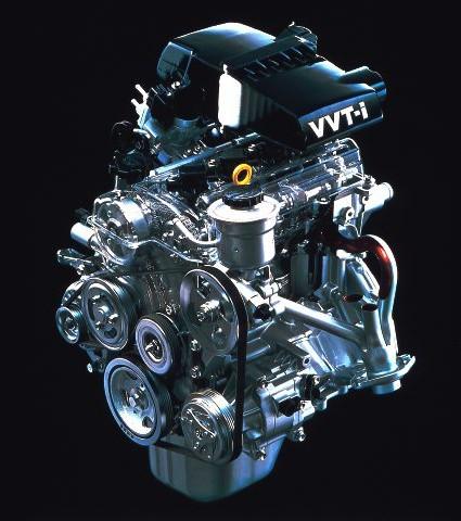
2 WHAT IS VVT? Variable Valve Timing (VVT),is a generic term for an automobile piston engine technology VVT allows the lift or duration or timing (some or all) of the intake or exhaust valves (or both) to be changed while the engine is in operation Two stroke engines use a power valve system to get similar results to VVT.
3 HISTORY The earliest variable valve timing systems came into existence in the nineteenth century on steam engines. Stephenson valve gear, as used on early steam locomotives supported variable cutoff, that is, changes to the time at which the admission of steam to the cylinders is cut off during the power stroke. Early approaches to variable cutoff coupled variations in admission cutoff with variations in exhaust cutoff. Admission and exhaust cutoff were decoupled with the development of the Corliss valve. These were widely used in constant speed variable load stationary engines, with admission cutoff, and therefore torque, mechanically controlled by a centrifugal governor. As poppet valves came into use, simplified valve gear using a camshaft came into use. With such engines, variable cutoff could be achieved with variable profile cams that were shifted along the camshaft by the governor. The earliest Variable valve timing systems on internal combustion engines were on the Lycoming R-7755 hyper engine, which had cam profiles that were selectable by the pilot. This allowed the pilot to choose full take off and pursuit power or economical cruising speed, depending on what was needed.
4 WHAT IS VVT-i The VVT-i system is designed to control the intake camshaft with in a range of 50 (of Crankshaft Angle ) to provide valve timing i.e. optimally suited to the engine condition.this improves the torque in all the speed ranges as well as fuel economy,and reducing exhaust emissions. This system controls the intake camshaft valve timing so as to obtain balance between the engine output, fuel consumption & emission control performance. The actual intake side valve timing is feed back by means of the camshaft position sensor for constant control to the target valve timing.
5 CONSTRUCTION The Variable Valve Timing (VVT) system includes ECM OCV VVT controller The ECM sends a target duty-cycle control signal to the OCV. This control signal regulates the oil pressure supplied to the VVT controller. Camshaft timing control is performed according to engine operating conditions such as the intake air volume, throttle valve position and engine coolant temperature. The ECM controls the OCV, based on the signals transmitted by several sensors. The VVT controller regulates the intake camshaft angle using oil pressure through the OCV. As a result, the relative positions of the camshaft and crankshaft are optimized, the engine torque and fuel economy improve, and the exhaust emissions decrease under overall driving conditions. The ECM detects the actual intake valve timing using signals from the camshaft and crankshaft position sensors, and performs feedback control. This is how the target intake valve timing is verified by the ECM.

6 The ECM optimizes the valve timing using the VVT system to control the intake camshaft. The VVT system includes the ECM, the OCV and the VVT controller. The ECM sends a target duty-cycle control signal to the OCV. This control signal regulates the oil pressure supplied to the VVT controller. The VVT controller can advance or retard the intake camshaft.
7

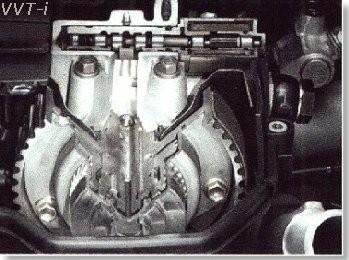
8 1.VVT-i Controller It consist of the housing driven from the timing chain & the vane coupled with the intake camshaft. The oil pressure sent from the advance or retard side path at the intake camshaft causes rotation in the VVT-i controller vane circumferential direction to vary the intake valve timing continuously. When the engine is stopped the intake camshaft will be in the most retard state to ensure start ability. When hydraulic pressure is not applied to the VVT-i controller immediately after the engine has been started, the lock pin locks the movement of the VVT-i controller to prevent a knocking noise.
9 2.Camshaft Timing Oil Control valve The camshaft timing oil control valve controls the spool valve position in accordance with the duty-cycle control from the ECM.This allows the hydraulic pressure to be applied to the VVT-i controller advance or retard side

10 OPERATION The camshaft timing oil control valve selects the path according to the advance, retard or hold signal from the ECM.The VVT-i controller rotates the intake camshaft in the timing advance or retard position or holds it according to the position where the oil pressure is applied.
11
12 In proportion to the engine speed, intake air volume throttle position and water temperature, the ECM calculates optimal valve timing under each driving condition & controls the camshaft timing oil control valve. In addition ECM uses signal from the camshaft position sensor & the crankshaft position sensor to detect the actual valve timing, thus performing feedback control to achieve the target valve timing
13
14
15 ADVANTAGES of vvt-i Improved torque & output Battery & fuel economy Reduced nitrogen oxide & hydrocarbon emissions
16 Applications of VVT-i Toyota VVT - Toyota 4A-GE 20-Valve engine introduced VVT in the 1992 Corolla GT-versions. VVT-i - Continuously varies the timing of the intake camshaft, or both the intake and exhaust camshafts (depending on application). VVTL-i - Continuously varies the timing of the intake valves. Varies duration, timing and lift of the intake and exhaust valves by switching between two different sets of cam lobes
17
VARIABLE VALVE TIMING SYSTEM > CAMRY 2.4L 4-CYL., CAMRY SOLARA 2.4L 4-CYL., CELICA, COROLLA, ECHO, HIGHLANDER 2.4L 4-CYL., MATRIX, MR2, PRIUS & RAV4
 Service Manual: ENGINE CONTROLS - THEORY & OPERATION VARIABLE VALVE TIMING SYSTEM 2003 Toyota Corolla 1.8L Eng LE NOTE: Variable Valve Timing (VVT) system may also be referred to as Variable Valve Timing
HINT: If DTC P0011 or P0012 is present, check the VVT (Variable Valve Timing) system. CIRCUIT DESCRIPTION. DTC Detection Conditions
 system. CIRCUIT DESCRIPTION. DTC Detection Conditions") 2005 Scion xb L4-1.5L (1NZ-FE) 10.20 Page 1 Computers and Control Systems: Diagnostic Trouble Code Tests and Associated Procedures P0012 DTC P0012 CAMSHAFT POSITION "A" -TIMING OVER-RETARDED (BANK 1) HINT:
2005 Scion xb L4-1.5L (1NZ-FE) 10.20 Page 1 Computers and Control Systems: Diagnostic Trouble Code Tests and Associated Procedures P0012 DTC P0012 CAMSHAFT POSITION "A" -TIMING OVER-RETARDED (BANK 1) HINT:
1GR-FE ENGINE CONTROL SYSTEM SFI SYSTEM
 72 1GR-FE EINE CONTROL SYSTEM SFI SYSTEM DTC DTC P0010 P0020 Camshaft Position "A" Actuator Circuit (Bank 1) Camshaft Position "A" Actuator Circuit (Bank 2) HINT: This DTC relates to the Oil Control Valve
Camshaft Position "A" Actuator Circuit (Bank 1)
") 72 2TR-FE EINE CONTROL SYSTEM SFI SYSTEM DTC P0010 Camshaft Position "A" Actuator Circuit (Bank 1) HINT: This DTC relates to the Oil Control Valve (OCV). DCRIPTION The Variable Valve Timing (VVT) system
72 2TR-FE EINE CONTROL SYSTEM SFI SYSTEM DTC P0010 Camshaft Position "A" Actuator Circuit (Bank 1) HINT: This DTC relates to the Oil Control Valve (OCV). DCRIPTION The Variable Valve Timing (VVT) system
DTC P0010 CAMSHAFT POSITION A ACTUATOR CIRCUIT (BANK 1)
") DIAGNOSTICS DTC P0010 CAMSHAFT POSITION A ACTUATOR CIRCUIT (BANK 1) 0543 05AIH08 CIRCUIT DESCRIPTION The Variable Valve Timing (VVT) system includes the ECM, the Oil Control Valve (OCV) and the VVT controller.
DIAGNOSTICS DTC P0010 CAMSHAFT POSITION A ACTUATOR CIRCUIT (BANK 1) 0543 05AIH08 CIRCUIT DESCRIPTION The Variable Valve Timing (VVT) system includes the ECM, the Oil Control Valve (OCV) and the VVT controller.
 Page 1 of 7 DTC P0016 CRANKSHAFT POSITION-CAMSHAFT POSITION CORRELATION (BANK 1 SENSOR A) COMPONENT LOCATION 2008 Kia Sorento 3.3L Eng LX Fig 1: Identifying Crankshaft Position-Camshaft Position Correlation
ENGINE 1ZZ-FE ENGINE DESCRIPTION EG-1 ENGINE - 1ZZ-FE ENGINE
 EG-1 ENGINE - 1ZZ-FE ENGINE ENGINE 1ZZ-FE ENGINE DESCRIPTION The VVT-i (Variable Valve Timing-intelligent) system, the DIS (Direct Ignition System), and a plastic intake manifold have been used on the
ELECTRONIC ENGINE CONTROLS
 2005 Jaguar S-Type (X200) V8-4.2L Vehicle > Powertrain Management > Computers and Control Systems > Description and Operation > Components ELECTRONIC ENGINE CONTROLS Electronic Engine Controls Vehicles
INTERNAL COMBUSTION ENGINE (SKMM 4413)
") INTERNAL COMBUSTION ENGINE (SKMM 4413) Dr. Mohd Farid bin Muhamad Said Room : Block P21, Level 1, Automotive Development Centre (ADC) Tel : 07-5535449 Email: mfarid@fkm.utm.my HISTORY OF ICE History of
INTERNAL COMBUSTION ENGINE (SKMM 4413) Dr. Mohd Farid bin Muhamad Said Room : Block P21, Level 1, Automotive Development Centre (ADC) Tel : 07-5535449 Email: mfarid@fkm.utm.my HISTORY OF ICE History of
SERVICE MANUAL. Common Rail System for HINO J08C/J05C Type Engine Operation. For DENSO Authorized ECD Service Dealer Only
 For DENSO Authorized ECD Service Dealer Only Diesel Injection Pump No. E-03-03 SERVICE MANUAL Common Rail System for HINO J08C/J05C Type Engine Operation June, 2003-1 00400024 GENERAL The ECD-U2 was designed
Ignition System Fundamentals
 Ignition System Fundamentals Chapter 37 Objectives Describe the functions of ignition system parts Explain the operation of points, electronic, and computer ignition systems Give an overview of the different
Introduction. Internal Combustion Engines
 Introduction Internal Combustion Engines Internal Combustion Engines A heat engine that converts chemical energy in a fuel into mechanical energy. Chemical energy first converted into thermal energy (Combustion)
Sensors & Controls. Everything you wanted to know about gas engine ignition technology but were too afraid to ask.
 Everything you wanted to know about gas engine ignition technology but were too afraid to ask. Contents 1. Introducing Electronic Ignition 2. Inductive Ignition 3. Capacitor Discharge Ignition 4. CDI vs
2 OPERATION 2.1 DDEC BENEFITS FEATURES DDEC SYSTEM--HOW IT WORKS DDEC RELATED PUBLICATIONS...
 2 OPERATION Section Page 2.1 DDEC BENEFITS... 2-3 2.2 FEATURES... 2-4 2.3 DDEC SYSTEM--HOW IT WORKS... 2-5 2.4 DDEC RELATED PUBLICATIONS... 2-23 (Rev. 2/03) All information subject to change without notice.
3406E Truck Engine 5EK01821-UP(SEBP ) - Document Structure. Media Number -RENR Publication Date -01/02/2008 Date Updated -07/02/2008
 - Document Structure. Media Number -RENR Publication Date -01/02/2008 Date Updated -07/02/2008") Page 1 of 11 Shutdown SIS Previous Screen Product: TRUCK ENGINE Model: 3406E TRUCK ENGINE 5EK Configuration: 3406E Truck Engine 5EK01821-UP Systems Operation 3406E Truck Engine Media Number -RENR1273-07
Page 1 of 11 Shutdown SIS Previous Screen Product: TRUCK ENGINE Model: 3406E TRUCK ENGINE 5EK Configuration: 3406E Truck Engine 5EK01821-UP Systems Operation 3406E Truck Engine Media Number -RENR1273-07
FUNDAMENTAL OF AUTOMOBILE SYSTEMS
 Prof. Kunalsinh Mechanical Engineering Dept. FUNDAMENTAL OF AUTOMOBILE SYSTEMS Prof. Kunalsinh kathia [MECHANICAL DEPT.] UNIT-2 [ENGINES] PART-1 Prof. Kunalsinh kathia [MECHANICAL DEPT.] Internal combustion
NEW FEATURES 1GR-FE ENGINE. 1. General FJ CRUISER NEW FEATURES
 FJ CRUISER NEW FEATURES 5 NEW FEATURES 1GR-FE ENGINE 1. General The 1GR-FE engine is a 4.0-liter, 24-valve DOHC V6 engine. In this engine, a Dual Variable Valve Timing-intelligent (Dual VVT-i) system,
DTC P050A Cold Start Idle Air Control System Performance. DTC P050B Cold Start Ignition Timing Performance
 260 1GR-FE EINE CONTROL SYSTEM SFI SYSTEM DTC P050A Cold Start Idle Air Control System Performance DTC P050B Cold Start Ignition Timing Performance DCRIPTION The Electronic Throttle Control System (ETCS)
Zoom and Print Options
 Vehicle» Engine, Cooling and Exhaust» Engine» Timing Components» Timing Chain» Service and Repair» Procedures» Timing Chain and Sprockets Replacement Timing Chain and Sprockets Replacement Tools Required
ENGINE AND EMISSION CONTROL
 17-1 GROUP 17 ENGINE AND EMISSION CONTROL CONTENTS ENGINE CONTROL 17-2 GENERAL INFORMATION 17-2 AUTO-CRUISE CONTROL SYSTEM 17-3 GENERAL INFORMATION 17-3 CONSTRUCTION AND OPERATION 17-5 17-7 GENERAL INFORMATION
Ignition control. The ignition system tasks. How is the ignition coil charge time and the ignition setting regulated?
 1 Ignition control The ignition system tasks To transform the system voltage (approximately 14 V) to a sufficiently high ignition voltage. In electronic systems this is normally above 30 kv (30 000 V).
Variable Valve Timing
 Service. Self-study programme 246 Variable Valve Timing with fluted variator Design and Function The demands on combustion engines continue to grow. On one hand, customers want more power and torque, while
CYCLICALLY OPERATING VALVES FOR MACHINES OR ENGINES (valves in general F16K)
") F01L CYCLICALLY OPERATING VALVES FOR MACHINES OR ENGINES (valves in general F16K) Valve-gear or valve arrangements, e.g. lift-valve gear; Lift-valve, i.e. cut-off apparatus with closure members having
F01L CYCLICALLY OPERATING VALVES FOR MACHINES OR ENGINES (valves in general F16K) Valve-gear or valve arrangements, e.g. lift-valve gear; Lift-valve, i.e. cut-off apparatus with closure members having
ENGINE MECHANICAL <134>
 11A-1 GROUP 11A ENGINE MECHANICAL CONTENTS GENERAL INFORMATION........ 11A-2.................. 11A-3 11A-2 The newly developed 1.1L 134910 engine features 3-cylinder, 12-valve, and double overhead
Data Unit Value Coolant temperature 0.436V (130 ) ~4.896V (-40 )
 ~4.896V (-40 )") 149000 153 1. ENGINE DATA LIST Data Unit Value Coolant temperature 0.436V (130 ) ~4.896V (40 ) Intake air temperature 40~130 (varies according to ambient air temperature or engine mode) Idle speed rpm
149000 153 1. ENGINE DATA LIST Data Unit Value Coolant temperature 0.436V (130 ) ~4.896V (40 ) Intake air temperature 40~130 (varies according to ambient air temperature or engine mode) Idle speed rpm
MIL "ON" DTC P0012 and/or P0022
 T-SB-0019-10 January 0, 010 Service Category Engine/Hybrid System Section Engine Control Market USA Applicability YEAR(S) MODEL(S) ADDITIONAL INFORMATION 010 Sequoia, Tundra Engine(s): 1UR, 3UR Introduction
2. Air Line AIR LINE FUEL INJECTION (FUEL SYSTEM) A: GENERAL B: MANIFOLD ABSOLUTE PRESSURE SENSOR FU(H4DOTC)-3
 A: GENERAL B: MANIFOLD ABSOLUTE PRESSURE SENSOR FU(H4DOTC)-3") W1860BE.book Page 3 Tuesday, January 28, 2003 11:01 PM 2. Air Line A: GENERAL The air filtered by the air cleaner enters the throttle body where it is regulated in the volume by the throttle valve and
W1860BE.book Page 3 Tuesday, January 28, 2003 11:01 PM 2. Air Line A: GENERAL The air filtered by the air cleaner enters the throttle body where it is regulated in the volume by the throttle valve and
DTC P0300 Random / Multiple Cylinder Misfire Detected. DTC P0301 Cylinder 1 Misfire Detected. DTC P0302 Cylinder 2 Misfire Detected
 1GR-FE EINE CONTROL SYSTEM SFI SYSTEM 169 DTC P0300 Random / Multiple Cylinder Misfire Detected DTC P0301 Cylinder 1 Misfire Detected DTC P0302 Cylinder 2 Misfire Detected DTC P0303 Cylinder 3 Misfire
DOWNLOAD OR READ : TOYOTA AE FE ENGINE PARTS PDF EBOOK EPUB MOBI
 DOWNLOAD OR READ : TOYOTA AE FE ENGINE PARTS PDF EBOOK EPUB MOBI Page 1 Page 2 toyota ae fe engine parts toyota ae fe engine pdf toyota ae fe engine parts Title: Toyota Ae Fe Engine Author: O'Reilly Media
P0016. P0016 Crankshaft Position-Camshaft Position Correlation(Bank I Sensor A) Component Location
 Component Location") 3/10/2018 P0016 (ALL Diagnostic Trouble Codes ( DTC )) - ALLDATA 2006 Kia Truck Sorento 2WD V6-3.5L Vehicle > ALL Diagnostic Trouble Codes ( DTC ) > Testing and Inspection > P Code Charts P0016 P0016 Crankshaft
3/10/2018 P0016 (ALL Diagnostic Trouble Codes ( DTC )) - ALLDATA 2006 Kia Truck Sorento 2WD V6-3.5L Vehicle > ALL Diagnostic Trouble Codes ( DTC ) > Testing and Inspection > P Code Charts P0016 P0016 Crankshaft
PRODUCT INFORMATION DF250SS DF200SS DF150SS DF115SS
 PRODUCT INFORMATION DF250SS DF200SS DF150SS DF115SS In A Word: EXCITEMENT Suzuki is bringing a new level of excitement to the water with its SS-Series 4-stroke outboards. 115, 150, 200 and 250 horsepower
E - THEORY/OPERATION - TURBO
 E - THEORY/OPERATION - TURBO 1995 Volvo 850 1995 ENGINE PERFORMANCE Volvo - Theory & Operation 850 - Turbo INTRODUCTION This article covers basic description and operation of engine performance-related
5. Control System CONTROL SYSTEM FUEL INJECTION (FUEL SYSTEM) A: GENERAL FU(H4DOTC)-29
 A: GENERAL FU(H4DOTC)-29") W1860BE.book Page 29 Tuesday, January 28, 2003 11:01 PM 5. Control System A: GENERAL The ECM receives signals from various sensors, switches, and other control modules. Using these signals, it determines
W1860BE.book Page 29 Tuesday, January 28, 2003 11:01 PM 5. Control System A: GENERAL The ECM receives signals from various sensors, switches, and other control modules. Using these signals, it determines
ENGINE CONTROL SYSTEM. 1. General ENGINE 1G-FE ENGINE 53. The engine control system for the 1G-FE engine has following system.
 ENGINE 1G-FE ENGINE 53 ENGINE CONTROL SYSTEM 1. General The engine control system for the 1G-FE engine has following system. System EFI Electronic Fuel Injection ESA Electronic Spark Advance VVT-i Variable
DTC Table (Extended Code)
") In4 DTC Table (Extended Code) DTC Document Title See Page P0010 OCV for VVT Monitor Co13 P0011 P0012 Valve Timing i Monitor Co6 P0016 P0018 VVT System Monitor Co8 P0020 OCV for VVT Monitor Co13 P0021 P0022
In4 DTC Table (Extended Code) DTC Document Title See Page P0010 OCV for VVT Monitor Co13 P0011 P0012 Valve Timing i Monitor Co6 P0016 P0018 VVT System Monitor Co8 P0020 OCV for VVT Monitor Co13 P0021 P0022
TOYOTA TUNDRA NEW FEATURES. The main components of the 2UZ-FE engine control system are as follows:
 60 TOYOTA TUNDRA NEW FEATURES Main Components of Engine Control System ) General The main components of the 2UZ-FE engine control system are as follows: 05 Toyota Tundra 04 4Runner Component Outline Quantity
Fig.11 Powertrain Control Module (PCM)
") 2003 Dodge or Ram Truck Caravan V6-3.3L VIN R Vehicle > Powertrain Management > Relays and Modules - Powertrain Management > Relays and Modules - Computers and Control Systems > Engine Control Module >
2003 Dodge or Ram Truck Caravan V6-3.3L VIN R Vehicle > Powertrain Management > Relays and Modules - Powertrain Management > Relays and Modules - Computers and Control Systems > Engine Control Module >
ENGINE REMOVAL Install: Exhaust pipe 1 5. Tighten: Nuts (exhaust pipe) 2. Exhaust pipe nut 20 Nm (2.0 m kgf, 14 ft lbf) 6.
 2. Exhaust pipe nut 20 Nm (2.0 m kgf, 14 ft lbf) 6.") ENGINE REMOVAL 4. Install: Gasket New Exhaust pipe 1 5. Tighten: Nuts (exhaust pipe) 2 Exhaust pipe nut 20 Nm (2.0 m kgf, 14 ft lbf) 6. Install: Clamp Slide the clamp onto the end of the muffler and insert
ENGINE REMOVAL 4. Install: Gasket New Exhaust pipe 1 5. Tighten: Nuts (exhaust pipe) 2 Exhaust pipe nut 20 Nm (2.0 m kgf, 14 ft lbf) 6. Install: Clamp Slide the clamp onto the end of the muffler and insert
DTC P050A Cold Start Idle Air Control System Performance. DTC P050B Cold Start Ignition Timing Performance
 278 2UZ-FE EINE CONTROL SYSTEM SFI SYSTEM DTC P050A Cold Start Idle Air Control System Performance DTC P050B Cold Start Ignition Timing Performance DCRIPTION The Electronic Throttle Control System (ETCS)
The TL Series is available with either a 3.2-liter V-6 or a 2.5-liter, inline fivecylinder,
 OVERVIEW The TL Series is available with either a 3.2-liter V-6 or a 2.5-liter, inline fivecylinder, engine. The 3.2TL engine, like all other Acura engines, is made of aluminum alloy and is equipped with
DTC P0300 Random / Multiple Cylinder Misfire Detected
 162 DTC P0300 Random / Multiple Cylinder Misfire Detected DTC P0301 Cylinder 1 Misfire Detected DTC P0302 Cylinder 2 Misfire Detected DTC P0303 Cylinder 3 Misfire Detected DTC P0304 Cylinder 4 Misfire
5. Control System CONTROL SYSTEM FUEL INJECTION (FUEL SYSTEM) A: GENERAL. FU(STi)-27
 A: GENERAL. FU(STi)-27") W1860BE.book Page 27 Tuesday, January 28, 2003 11:01 PM 5. Control System A: GENERAL The ECM receives signals from various sensors, switches, and other control modules. Using these signals, it determines
W1860BE.book Page 27 Tuesday, January 28, 2003 11:01 PM 5. Control System A: GENERAL The ECM receives signals from various sensors, switches, and other control modules. Using these signals, it determines
MULTIPORT FUEL SYSTEM (MFI) <2.4L ENGINE>
 <2.4L ENGINE>") 13B-1 GROUP 13B MULTIPORT FUEL SYSTEM (MFI) CONTENTS GENERAL DESCRIPTION 13B-2 CONTROL UNIT 13B-5 SENSOR 13B-7 ACTUATOR 13B-24 FUEL INJECTION CONTROL 13B-31 IGNITION TIMING AND CONTROL FOR
13B-1 GROUP 13B MULTIPORT FUEL SYSTEM (MFI) CONTENTS GENERAL DESCRIPTION 13B-2 CONTROL UNIT 13B-5 SENSOR 13B-7 ACTUATOR 13B-24 FUEL INJECTION CONTROL 13B-31 IGNITION TIMING AND CONTROL FOR
REDESIGNED MODULES FOR THE SECTOR AUTOMOBILE UNDER MODULAR EMPLOYABLE SKILLS (MES)
") REDESIGNED MODULES FOR THE SECTOR OF AUTOMOBILE UNDER MODULAR EMPLOYABLE SKILLS (MES) Redesigned in - 2014 By Government of India Directorate General of Employment & Training Ministry of Labour & Employment
REDESIGNED MODULES FOR THE SECTOR OF AUTOMOBILE UNDER MODULAR EMPLOYABLE SKILLS (MES) Redesigned in - 2014 By Government of India Directorate General of Employment & Training Ministry of Labour & Employment
2012 Chevy Truck Equinox FWD L4-2.4L Vehicle > Locations > Components
 2012 Chevy Truck Equinox FWD L4-2.4L Vehicle > Locations > Components 2012 Chevy Truck Equinox FWD L4-2.4L Vehicle > Powertrain Management > Fuel Delivery and Air Induction > Description and Operation
16.01 Theory Module INPUTS
 16.01 Theory Module INPUTS Crankshaft position sensor Camshaft position sensor Knock sensor (some engine types) Barometric pressure sensor Intake air temperature sensor Engine coolant temperature sensor
EMISSION CONTROL (AUX. EMISSION CONTROL DEVICES) H6DO
 H6DO") EMISSION CONTROL (AUX. EMISSION CONTROL DEVICES) H6DO SYSTEM OVERVIEW 1. System Overview There are three emission control systems, which are as follows: Crankcase emission control system Exhaust emission
EMISSION CONTROL (AUX. EMISSION CONTROL DEVICES) H6DO SYSTEM OVERVIEW 1. System Overview There are three emission control systems, which are as follows: Crankcase emission control system Exhaust emission
Oregon Fuel Injection
 2001 2006 Dodge Mercedes - Freightliner Sprinter Diagnostics In order to do proper diagnostics you will need a scan tool and some special tools available from Mopar Special Tools http://mopar.snapon.com.
Unit Plan SAFE Automotive (Survival Automotives For Everyone) Unit: Fundamental Operation of Vehicles
 Unit: Fundamental Operation of Vehicles") Unit Plan SAFE Automotive (Survival Automotives For Everyone) Fundamental Operation of Vehicles Unit: Fundamental Operation of Vehicles Year:2012 Duration: 1 Week 1. List any special needs of students
Unit Plan SAFE Automotive (Survival Automotives For Everyone) Fundamental Operation of Vehicles Unit: Fundamental Operation of Vehicles Year:2012 Duration: 1 Week 1. List any special needs of students
A. Aluminum alloy Aluminum that has other metals mixed with it.
 ENGINE REPAIR UNIT 1: ENGINE DESIGN LESSON 1: PRINCIPLES OF ENGINE DESIGN I. Terms and definitions A. Aluminum alloy Aluminum that has other metals mixed with it. B. Bearing A device that allows movement
Exhaust System - 2.2L Diesel
 Page 1 of 9 Published: Mar 8, 2007 Exhaust System - 2.2L Diesel COMPONENT LOCATION - WITH DIESEL PARTICULATE FILTER Item Part Number Description 1 Exhaust manifold (ref only) 2 Pressure differential sensor
Fundamentals of Small Gas Engines
 Fundamentals of Small Gas Engines Objectives: Describe the four-stroke cycle engine operation and explain the purpose of each stroke Explain the concept of valve timing Describe two-stroke engine operation
Engine Brake, Design and Function. This information covers the design and function of the Volvo Engine Brake (VEB) on the Volvo D11F engine.
 on the Volvo D11F engine.") Volvo Trucks North America Greensboro, NC USA Service Bulletin Trucks ate Group No. Page 11.2006 253 53 1(7) Engine Brake esign and Function 11F Engine Brake, esign and Function W2005865 This information
Volvo Trucks North America Greensboro, NC USA Service Bulletin Trucks ate Group No. Page 11.2006 253 53 1(7) Engine Brake esign and Function 11F Engine Brake, esign and Function W2005865 This information
EMISSION CONTROL (AUX. EMISSION CONTROL DEVICES) H4DOTC
 H4DOTC") EMISSION CONTROL (AUX. EMISSION CONTROL DEVICES) H4DOTC SYSTEM OVERVIEW 1. System Overview There are three emission control systems, which are as follows: Crankcase emission control system Exhaust emission
EMISSION CONTROL (AUX. EMISSION CONTROL DEVICES) H4DOTC SYSTEM OVERVIEW 1. System Overview There are three emission control systems, which are as follows: Crankcase emission control system Exhaust emission
M-6007-A50NA Engine Specifications and Owner's Manual
 M-6007-A50NA Engine Specifications and Owner's Manual Fordracingparts.com Techline 1-800-367-3788 Page 1 of 11 IS-1850-0377 Please visit www.fordracingparts.com for the most current instruction information.!!!
EMISSION CONTROL (AUX. EMISSION CONTROL DEVICES) H4SO
 H4SO") EMISSION CONTROL (AUX. EMISSION CONTROL DEVICES) H4SO SYSTEM OVERVIEW 1. System Overview There are three emission control systems, which are as follows: Crankcase emission control system Exhaust emission
EMISSION CONTROL (AUX. EMISSION CONTROL DEVICES) H4SO SYSTEM OVERVIEW 1. System Overview There are three emission control systems, which are as follows: Crankcase emission control system Exhaust emission
ENGINE MECHANICAL <2.0L ENIGNE>
 11A-1 GROUP 11A ENGINE MECHANICAL CONTENTS GENERAL DESCRIPTION......... 11A-2.................. 11A-3 11A-2 This model is equipped with a newly developed 4B11 engine. It is a 4-cylinder,
3GR-FSE ENGINE CONTROL SYSTEM
 ENGINE EG 13 Engine Control System Description This engine controls the following systems in a highly accurate manner: Sequential Fuel Injection (SFI), Electronic Spark Advance (ESA), Electronic Throttle
FLEXIBILITY WITHOUT COMPROMISE ELECTRIC CAM PHASING ANDREW MLINARIC 9/6/2018
 FLEXIBILITY WITHOUT COMPROMISE ELECTRIC CAM PHASING ANDREW MLINARIC 1 Hydraulic Variable Cam Phasing Systems Challenges: Large volume of oil required High oil pressure requirements Parasitic losses Low
Technical Service BULLETIN
 Technical Service BULLETIN May 19, 2003 Title: Models: 00 02 Celica GTS EG010-03 ENGINE Introduction In some cases, owners of 2000 2002 model year Celica GTS vehicles equipped with the 2ZZ GE engine may
FUEL SYSTEM FUEL INJECTION SYSTEM. Electronic Control of Fuel System
 07 5 FUEL INJECTION SYSTEM Electronic Control of Fuel System IMV valve Low and high pressure pump Fuel temperature sensor High pressure pump Water separator Water detection sensor Fuel filter System composition
(3) (4) (6) (5) (10) (9) (8) (7)
 (4) (6) (5) (10) (9) (8) (7)") 3. Fuel System A: GENERAL The fuel pressurized by the fuel tank inside pump is delivered to each fuel injector by way of the fuel pipe and fuel filter. Fuel injection pressure is regulated to an optimum
3. Fuel System A: GENERAL The fuel pressurized by the fuel tank inside pump is delivered to each fuel injector by way of the fuel pipe and fuel filter. Fuel injection pressure is regulated to an optimum
Fuel Metering System Component Description
 1999 Chevrolet/Geo Tahoe - 4WD Fuel Metering System Component Description Purpose The function of the fuel metering system is to deliver the correct amount of fuel to the engine under all operating conditions.
Classification: Reference: Date: VE30DE CAM TIMING
 Classification: Reference: Date: EM93-002 NTB93-126 September 2, 1993 VE30DE CAM TIMING APPLIED VEHICLE(S): All equipped with VE30DE Engine SERVICE INFORMATION When servicing VE30DE engine cylinder heads,
Bi-Fuel Conversion for High Speed Diesel Engins
 Bi-Fuel Conversion for High Speed Diesel Engins Introduction The bi-fuel system modifies standard heavy-duty diesel engines to operate on diesel and gas simultaneously. The gas is used as main fuel and
Systems Operation, Testing and Adjusting
 Systems Operation, Testing and Adjusting 3176C and 3196 Engines for Caterpillar Built Machines S/N: 4SS00001-UP (Excavators 345B) S/N: 7ZR01004 (ENGINE) Use the bookmarks for navigation inside of the manual
Kubota Engine Training: WG1605, spark ignited
 Kubota Engine Training: WG1605, spark ignited WG1605 Engine Training: System Overviews Mechanical Components Electronic Components and Sensors Operation Service Tool Fuel System Overview: Fuel System Overview:
Lotus Service Notes Section EMD
 ENGINE MANAGEMENT SECTION EMD Lotus Techcentre Sub-Section Page Diagnostic Trouble Code List EMD.1 3 Component Function EMD.2 8 Component Location EMD.3 10 Diagnostic Guide EMD.4 11 CAN Bus Diagnostics;
ProECU Subaru BRZ Toyota GT86 Scion FR-S
 ProECU Subaru BRZ Toyota GT86 Scion FR-S DTC List 2012-onward Model Year v1.0 Engine DTC List P000A Camshaft Position "A" - Timing Slow Response Bank 1 P000B Camshaft Position "B" - Timing Slow Response
GMC's Truck Built V-6 Engine!
 [GMC Main] [6066 GMC Club] [What's New] [] [Support] [Memorabilia] [GMC Gallery] [GMC ID] [VIN Numbers] [Contact] [ Discussion Group] [Lighting & Electrical] [V6 Performance] GMC's Truck Built V-6 Engine!
Engine mechanics. Crankcase ventilation outlet
 Engine mechanics Crankcase ventilation outlet The gases are drawn out of the crankcase by the vacuum in the intake manifold. The oil is separated from the gases in the labyrinth and in the cyclone oil
Module 13: Mechanical Fuel Injection Diagnosis and Repair
 Terms and Definitions Parts of Injection Nozzles Types of Nozzle Valves Operation of an Injection Nozzle Fuel Flow Through the Unit Injector Optional Features on Fuel Injection Pumps Main Parts of a Distributor-Type
MARINE.HONDA.COM.AU. BF150 (150hp Outboard)
") MARINE.HONDA.COM.AU BF150 (150hp Outboard) The BF150 sets the standard in innovation with its advanced inline fourcylinder technology, placing this engine in a league of its own. INTRODUCTION MAXIMUM POWER
MARINE.HONDA.COM.AU BF150 (150hp Outboard) The BF150 sets the standard in innovation with its advanced inline fourcylinder technology, placing this engine in a league of its own. INTRODUCTION MAXIMUM POWER
Camshaft Timing For Toyota 4e Fe Engine
 We have made it easy for you to find a PDF Ebooks without any digging. And by having access to our ebooks online or by storing it on your computer, you have convenient answers with camshaft timing for
PERFORMER-PLUS Camshaft/Lifters/Lube Kit CATALOG #2157 MODEL: c.i.d. Pontiac V8, 1965 & later
 PERFORMER-PLUS Camshaft/Lifters/Lube Kit CATALOG #2157 MODEL: 350-455 c.i.d. Pontiac V8, 1965 & later CAMSHAFT: Edelbrock Performer-Plus camshafts are ground specifically for use with the corresponding
1GR-FE ENGINE MECHANICAL: TIMING CHAIN: INSTALLATION (2007 4Runner) Model Year: 2007 Model: 4Runner Doc ID: RM WS002X
 Model Year: 2007 Model: 4Runner Doc ID: RM WS002X") Last Modified: 4-26-2007 Service Category: Engine/Hybrid System 1.6 A Section: Engine Mechanical Model Year: 2007 Model: 4Runner Doc ID: RM0000029WS002X Title: 1GR-FE ENGINE MECHANICAL: TIMING CHAIN: INSTALLATION
Last Modified: 4-26-2007 Service Category: Engine/Hybrid System 1.6 A Section: Engine Mechanical Model Year: 2007 Model: 4Runner Doc ID: RM0000029WS002X Title: 1GR-FE ENGINE MECHANICAL: TIMING CHAIN: INSTALLATION
3GR-FSE FUEL. Fuel Pump (High Pressure) Cold Start Fuel Injector *
 Cold Start Fuel Injector *") ENGINE EG 75 General This engine uses the D-4 (Direct injection 4-stroke gasoline engine) system. A (low pressure) fuel pump located inside the fuel tank pumps fuel to the high-pressure fuel pump located
ENGINE EG 75 General This engine uses the D-4 (Direct injection 4-stroke gasoline engine) system. A (low pressure) fuel pump located inside the fuel tank pumps fuel to the high-pressure fuel pump located
PERFORMER RPM Camshaft/Lifters/Lube Kit CATALOG #7102 MODEL: c.i.d. Chevrolet V8, 1957 & later
 PERFORMER RPM Camshaft/Lifters/Lube Kit CATALOG #7102 MODEL: 262-400 c.i.d. Chevrolet V8, 1957 & later CAMSHAFT: Edelbrock Performer RPM camshafts are ground specifically for use with the corresponding
SUPERCHARGER AND TURBOCHARGER
 SUPERCHARGER AND TURBOCHARGER 1 Turbocharger and supercharger 2 To increase the output of any engine more fuel can be burned and make bigger explosion in every cycle. i. One way to add power is to build
2012 Honda Crosstour EX ENGINE Cylinder Head - (4-CYL)
") Fig. 4: Identifying Cylinder Head Components Location (3 Of 3) ENGINE COMPRESSION INSPECTION NOTE: After this inspection, you must reset the PCM. Otherwise, the PCM will continue to stop the fuel injectors
Fig. 4: Identifying Cylinder Head Components Location (3 Of 3) ENGINE COMPRESSION INSPECTION NOTE: After this inspection, you must reset the PCM. Otherwise, the PCM will continue to stop the fuel injectors
ENGINE & WORKING PRINCIPLES
 ENGINE & WORKING PRINCIPLES A heat engine is a machine, which converts heat energy into mechanical energy. The combustion of fuel such as coal, petrol, diesel generates heat. This heat is supplied to a
Exhaust After-Treatment System. This information covers design and function of the Exhaust After-Treatment System (EATS) on the Volvo D16F engine.
 on the Volvo D16F engine.") Volvo Trucks North America Greensboro, NC USA DService Bulletin Trucks Date Group No. Page 1.2007 258 44 1(6) Exhaust After-Treatment System Design and Function D16F Exhaust After-Treatment System W2005772
Volvo Trucks North America Greensboro, NC USA DService Bulletin Trucks Date Group No. Page 1.2007 258 44 1(6) Exhaust After-Treatment System Design and Function D16F Exhaust After-Treatment System W2005772
DIAGNOSTIC TROUBLE CODE CHART (SAE Controlled)
") 1MZFE ENGINE EG2404 (SAE Controlled) HINT: Parameters listed in the chart may not be exactly the same as your reading due to the type of instrument or other factors. DTC No. Detection Item Diagnostic Trouble
1MZFE ENGINE EG2404 (SAE Controlled) HINT: Parameters listed in the chart may not be exactly the same as your reading due to the type of instrument or other factors. DTC No. Detection Item Diagnostic Trouble
COMPREHENSIVE COMPONENTS MONITORING
 Automobili Lamborghini s.p.a. OBDII MY 09 Section 16 Page 1 COMPREHENSIVE COMPONENTS MONITORING Automobili Lamborghini s.p.a. OBDII MY 09 Section 16 Page 2 Description Automobili Lamborghini s.p.a. OBDII
ELECTRONIC CONTROL SYSTEM. 1. General CH-16 CHASSIS - U340E AUTOMATIC TRANSAXLE
 CH-16 ELECTRONIC CONTROL SYSTEM 1. General The electronic control system of the U340E automatic transaxle consists of the controls listed below. System Clutch Pressure Control (See page CH-20) Line Pressure
Lotus Service Notes Section EMR
 ENGINE MANAGEMENT SECTION EMR Lotus Techcentre Sub-Section Page Diagnostic Trouble Code List EMR.1 3 Component Function EMR.2 7 Component Location EMR.3 9 Diagnostic Guide EMR.4 11 CAN Bus Diagnostics;
CENTAC Inlet and Bypass Valve Positioners
 CENTAC Inlet and Bypass Valve Positioners INGERSOLL-RAND AIR COMPRESSORS INLET AND BYPASS VALVE POSITIONERS Copyright Notice Copyright 1992, 1999 Ingersoll-Rand Company THIS CONTENTS OF THIS MANUAL ARE
DTC P0300 Random / Multiple Cylinder Misfire Detected. DTC P0301 Cylinder 1 Misfire Detected. DTC P0302 Cylinder 2 Misfire Detected
 1GR-FE EINE CONTROL SYSTEM SFI SYSTEM 171 DTC P0300 Random / Multiple Cylinder Misfire Detected DTC P0301 Cylinder 1 Misfire Detected DTC P030 Cylinder Misfire Detected DTC P0303 Cylinder 3 Misfire Detected
Internal Combustion Engines
 Introduction Lecture 1 1 Outline In this lecture we will learn about: Definition of internal combustion Development of the internal combustion engine Different engine classifications We will also draw
MULTIPORT FUEL SYSTEM (MFI)
") 13A-1 GROUP 13A CONTENTS GENERAL INFORMATION...13A-2 CONTROL UNIT...13A-7 SENSOR...13A-9 ACTUATOR...13A-26 FUEL INJECTION CONTROL...13A-31 IGNITION TIMING AND CONTROL FOR CURRENT CARRYING TIME...13A-36
13A-1 GROUP 13A CONTENTS GENERAL INFORMATION...13A-2 CONTROL UNIT...13A-7 SENSOR...13A-9 ACTUATOR...13A-26 FUEL INJECTION CONTROL...13A-31 IGNITION TIMING AND CONTROL FOR CURRENT CARRYING TIME...13A-36
 Page 1 of 12 Section 2.3 N2 Electronic Unit Injector The N2 Electronic Unit Injector (EUI) is a lightweight, compact unit that injects diesel fuel directly into the combustion chamber. See Figure "N2 Electronic
IGNITION SYSTEM COMPONENTS AND OPERATION
 69 IGNITION SYSTEM COMPONENTS AND OPERATION Figure 69-1 A point-type distributor from a hot rod being tested on a distributor machine. WARNING: The spark from an ignition coil is strong enough to cause
DIAGNOSTIC TROUBLE CODE CHART
 DIAGNOSTIC TROUBLE CODE CHART 05 35 HINT: As for the vehicle for MEXICO, refer to Repair Manual 2003 COROLLA MATRIX (Pub. No. RM940U). Parameters listed in the chart may not be exactly the same as your
I.C ENGINES. CLASSIFICATION I.C Engines are classified according to:
 I.C ENGINES An internal combustion engine is most popularly known as I.C. engine, is a heat engine which converts the heat energy released by the combustion of the fuel taking place inside the engine cylinder
ENGINE GENERAL ENGINE GENERAL GENERAL OVERVIEW AND OPERATION PROCESS 1. STRUCTURE...
 GENERAL 1. STRUCTURE... 3 OVERVIEW AND OPERATION PROCESS 1. ENGINE CONTROLS COMPONENTS... 2. INTAKE SYSTEM COMPONENTS... 3. EXHAUST SYSTEM COMPONENTS... 4. LUBRICATION SYSTEM COMPONENTS... 5. COOLING SYSTEM
1ZZ-FE ENGINE CONTROL SYSTEM SFI SYSTEM. DTC P0300 Random / Multiple Cylinder Misfire Detected ECM
 164 DTC P0300 Random / Multiple Cylinder Misfire Detected DTC P0301 Cylinder 1 Misfire Detected DTC P0302 Cylinder 2 Misfire Detected DTC P0303 Cylinder 3 Misfire Detected DTC P0304 Cylinder 4 Misfire
3. Engine Control System Diagram
 ENGINE - 2UZ-FE ENGINE 59 3. Engine Control System Diagram Ignition Switch Fuel Pump Relay Fuel Pump Resister Circuit Opening Fuel Relay Filter Intake Temp. Mass Air Flow Meter Throttle Position Fuel Pump
a. Turn the crankshaft pulley, and align its groove with the timing mark "0" of the timing chain cover.
 Adjustments ADJUSTMENT HINT: Inspect and adjust the valve clearance when the engine is cold. 1. REMOVE CYLINDER HEAD COVER 2. SET NO. 1 CYLINDER TO TDC/COMPRESSION a. Turn the crankshaft pulley, and align
DTC P0351 Ignition Coil "A" Primary / Secondary Circuit. DTC P0352 Ignition Coil "B" Primary / Secondary Circuit
 186 TR-FE ENGINE CONTROL SYSTEM SFI SYSTEM DTC P0351 Ignition Coil "A" Primary / Secondary Circuit DTC P035 Ignition Coil "B" Primary / Secondary Circuit DTC P0353 Ignition Coil "C" Primary / Secondary
1012-Electrical Diagrams
 Term Absolute Pressure 1012-Electrical Diagrams Definition Total or true pressure. Gauge pressure plus atmospheric pressure. Absolute that includes the atmospheric pressure in its reading. This sensor