Multi Engine Airplane Guide
|
|
|
- Loren Clark
- 6 years ago
- Views:
Transcription

1 Multi Engine Airplane Guide Tecnam P2006T
2 TABLE OF CONTENTS Introduction to Multi Engine Aircraft... 1 V Speeds... 2 Performance and Limitations... 4 Engine Ceilings... 4 Single Engine Climb Performance... 5 Multi Engine Aerodynamics... 6 Induced Flow... 6 Turning Tendencies... 6 Engine Failures... 9 What Happens When an Engine Fails... 9 Critical Engine P Factor Accelerated Slipstream Torque VMC VMC For Certification FAR Recognizing and Recovering From VMC VMC vs. Stall Speed Factors Affecting VMC Power Density Altitude C.G. Location Gear Position Propeller Windmilling vs. Feathered Propeller Flaps Down Weight Bank Angle Amount of Horizontal Component of Lift Angle of Attack on the Rudder Rudder Effectiveness Direction of Relative Wind Slipping vs. Coordinated Amount of Fuselage Lift Produced Bank Angle Examples i
3 0 of Bank Bank Toward Operating Engine Bank Towards Operating Engine Bank Towards Inoperative Engine Summary of Bank Angle Relating to VMC Speed and Drag Critical Engine Failure In Ground Effect Chart Of Factors Affecting VMC Tecnam P2006T Systems Key Numbers Airframe Fuselage Empennage Flight Controls Engine Power Plant Lubrication Engine Features Power Plant Electrical Gearbox Pedestal Overhead Panel Internal Lights External Lights Fuel System Landing Gear Brakes Ventilation Cabin Heat Safety Belts Doors Baggage Compartment Placards Electrical ii
4 INTRODUCTION TO MULTI ENGINE AIRCRAFT The ERAU Multi Engine Aircraft Guide provides supplemental information to assist you in learning the many factors when dealing with flying a multi engine ( light twin ) airplane. The term light twin, although not formally defined in the Federal Aviation Regulations, is defined as a small multi engine airplane with a maximum certificated takeoff weight of 6,000 pounds or less. The basic differences between operating multi engine airplanes and single engine airplanes are that multi engine airplanes are: Generally capable of flying at faster airspeeds and higher altitudes, Typically larger in size and have more complex systems, and More demanding and that pilots have additional knowledge and understanding of the conditions associated with operating with one engine inoperative. While there are a few differences between taxiing single engine and multi engine airplanes, the most noticeable difference is typically the increase in wingspan. With an increase in wingspan, there is an even greater need for vigilance when taxiing in close quarters. In addition, the multi engine airplane may not be as nimble or responsive to steering inputs as the smaller single engine airplane. One advantage of a multi engine airplane over a single engine airplane is the differential power capability. Turning the airplane during taxi with the assistance from differential power minimizes the need for brakes during turns and while maintaining the same turning radius. Differential power, however, does NOT need to be used during every turn, or as the primary way to turn the airplane. It is also important to remember to keep engine power to a minimum and not ride the brakes. Unless otherwise directed by the AFM/POH, all ground operations should be conducted with the cowl flaps fully open to ensure adequate engine cooling. When operating a multi engine airplane with one engine inoperative, the penalties for loss of an engine are twofold: performance and control. The most obvious problem related to airplane performance is the loss of power (50%). This loss reduces climb performance by 80 90%, sometimes even more. The second problem affects aircraft control caused by the remaining thrust, which is now asymmetrical. Attention to both of these factors is crucial in maintaining safe, one engine inoperative flight. For pilots, flying a multi engine airplane is an exhilarating yet challenging experience. To take full advantage of the airplanes capabilities, performance, and safety, the pilot must be well trained, knowledgeable, and proficient. 1
5 V SPEEDS Multi Engine airplanes use the same V speeds as single engine airplanes. However, multi engine airplanes have additional V speeds and airspeed indicator markings relating to one engine inoperative flight. Unless otherwise noted, V speeds given in the AFM/POH/IM apply to sea level pressure, and standard day conditions at the airplane s maximum certificated takeoff weight. Performance speeds will vary with aircraft weight, configuration, and atmospheric conditions. VR Rotation speed. The speed at which back pressure is applied to rotate the airplane to a takeoff attitude. VLOF Lift off speed. The speed at which the airplane leaves the surface. Some manufacturers reference takeoff performance data to VR, others to VLOF. VX Best angle of climb speed. The speed at which the airplane will gain the greatest altitude for a given distance of forward travel. VXSE Best angle of climb speed with one engine inoperative. VY Best rate of climb speed. The speed at which the airplane will gain the most altitude for a given unit of time. VYSE Best rate of climb speed with one engine inoperative. Marked with a blue radial line on most airspeed indicators. VSSE Safe, intentional one engine inoperative speed. Originally known as safe singleengine speed, it is the minimum speed to intentionally render the critical engine inoperative. Required by 14 CFR Part 23, Airworthiness Standards, to be established and published in the AFM/POH. VMC Minimum control speed with the critical engine inoperative. The minimum speed at which directional control can be maintained under a very specific set of circumstances outlined in 14 CFR Part 23, Airworthiness Standards. Marked with a red radial line on most airspeed indicators. VMC only addresses directional control. There is no requirement that the airplane be capable of climbing at this airspeed. 2

6 Tecnam P2006T Vmc= 62 KIAS Red Line Vyse= 84 KIAS Blue Line If an engine failure occurs below VMC while the airplane is on the ground, the takeoff must be rejected. Directional control can only be maintained by promptly closing both throttles and using rudder and brakes as required. If an engine fails below VMC while airborne, directional control is not possible with the remaining engine producing takeoff power. So for safety reasons, the airplane should never be airborne during takeoff before the airspeed reaches AND exceeds VMC. After liftoff, gain altitude as rapidly as possible. Once leaving the ground, altitude gain is more important than achieving excess of airspeed. Altitude also gives the pilot time to think and react if an engine failure occurs. VY should be established and maintained until reaching a safe single engine maneuvering altitude. Considering terrain and obstructions, this is typically achieved at a minimum of AGL. There will be more information on all the factors involved in single engine operation of the airplane and the factors affecting VMC speed later in this guide. 3

7 PERFORMANCE AND LIMITATIONS Accelerate stop distance is the runway length required to accelerate to a specified speed (either VR or VLOF, as specified by the manufacturer), experience an engine failure, and bring the airplane to a complete stop. Tecnam does not publish accelerate-stop charts. Accelerate go distance is the horizontal distance required to continue the takeoff and climb to 50 AGL., assuming an engine failure occurs at VR or VLOF, as specified by the manufacturer (see diagram below). Tecnam does not publish accelerate-go charts. The FARs do not specifically require that the runway length be equal to or greater than the accelerate stop distance. Most AFM/POH publish accelerate stop distances only as an advisory. It becomes a limitation only when published in the limitations section of the AFM/POH. Using runway lengths of at least the accelerate stop distance is a good operating and safety practice. ENGINE CEILINGS All Engine Service Ceiling the highest altitude at which the airplane can maintain a steady rate of climb of 100 fpm with both engines operating at full power. All Engine Absolute Ceiling the altitude where climb is no longer possible with both engines operating at full power. Single Engine Service Ceiling the highest altitude at which the airplane can maintain a steady rate of climb of 50 fpm with one engine operating at full power and one engine s propeller feathered. Single Engine Absolute Ceiling the altitude where climb is no longer possible with one engine operating at full power and one engine s propeller feathered. If the airplane is flying above the single engine service ceiling and one engine fails in flight, the airplane will drift down from its current altitude to the single engine service ceiling. Above the single engine absolute ceiling, VYSE yields the minimum rate of sink. For example if an airplane s single engine absolute ceiling is 5,000 ft. and while cruising at 9,000 ft. an engine fails, the airplane will drift down (descend) to 5,000 ft. 4
8 SINGLE ENGINE CLIMB PERFORMANCE FAR provides the single engine climb performance requirements to airplane manufacturers for FAA certification of multi engine aircraft. For aircraft with a maximum weight of 6,000 lbs., or less and a VSO of 61 knots or less: The single engine rate of climb at 5,000 MSL must simply be determined with the 1. Critical engine inoperative and its propeller in the minimum drag position 2. Remaining engine(s) at no more than maximum continuous power 3. Landing gear retracted 4. Wing flaps retracted 5. Climb speed not less than 1.2VS1 The rate of climb could be a negative number meaning a descent There is no requirement for a single engine positive rate of climb at 5,000 ft., or any other altitude. For Aircraft with a maximum weight of 6,000 lbs. or less, and/or VSO more than 61 knots: If certified before February 4, 1991: the single engine rate of climb in feet per minute at 5,000 MSL must be equal to at least.027 VSO 2 (VSO Squared) If certified after February 4, 1991: maintain a steady climb gradient of at least 1.5 percent at a pressure altitude of 5,000 ft. with the 1. Critical engine inoperative and its propeller in the minimum drag position 2. Remaining engine(s) at no more than maximum continuous power 3. Landing gear retracted 4. Wing flaps retracted 5. Climb speed not less than 1.2 VS1 NOTE Do not confuse the date of type certification with the airplane s model year. Rate of climb is the altitude gain per unit of time. Climb gradient is the actual measure of altitude gained per 100 ft. of horizontal travel, expressed as a percentage. An altitude gain of 1.5 ft. per 100 ft. of horizontal travel (or 15 ft. per 1,000, or 150 ft. per 10,000) is a climb gradient of 1.5 percent. Climb gradient may also be expressed as a function of altitude gain per nautical mile, or as a ratio of the horizontal distance to the vertical distance (e.g., 50:1). Unlike rate of climb, the climb gradient is affected by wind. A climb gradient is improved with a headwind component and reduced with a tailwind component. 5

 also affect multi engine airplanes.")
9 MULTI ENGINE AERODYNAMICS INDUCED FLOW Looking at the airplane without the engines and the fuselage, the amount of lift created by the wings would look like this: Jeppesen Multi Engine Manual The propellers of the wing mounted engines create an accelerated flow or accelerated slipstream of air over the wings called induced flow. The amount of lift created by a multi engine airplane looks like this: Jeppesen Multi Engine Manual Induced flow does occur in single engine airplanes, but it is not as much of a factor because of the location of the engine in relation to the wings. TURNING TENDENCIES The turning tendencies that affect single engine airplanes (i.e. torque and P factor) also affect multi engine airplanes. Since the multi engine airplane has at least two engines, these effects are increased. Twin engine airplanes where the propellers for each engine rotate in the same direction are called conventional twins. To combat the torque and P factor tendencies, twin engine airplanes with counter rotating propellers, or propellers that rotate in opposite directions, and engines have been developed. The effects of torque and p factor with counter rotating propellers will cancel each other out, resulting in less rudder needed to oppose these forces. 6

10 Thrust Thr ust Thrust Thrust Coast Flight Training Multi-Engine Guide A Conventional Twin Result of Torque = Roll to the Left Resulting Torque Resulting Torque Propeller Rotation Propeller Rotation Result of P Factor = Yaw to the left Resulting Turn 7


11 Thrust Thrust Coast Flight Training Multi-Engine Guide A Counter Rotating Twin Result of Torque = NONE = Both Engines Cancel Each Other Out. Resulting Torque Resulting Torque Propeller Rotation Propeller Rotation Result of P Factor = NONE = Both Engines Cancel Each Other Out. No Turn Thrust Thrust 8


 over the wing from the operating engine and lack of induced flow (accelerated slipstream) over")
12 Thrust Coast Flight Training Multi-Engine Guide ENGINE FAILURES WHAT HAPPENS WHEN AN ENGINE FAILS Two motions happen when an engine fails: YAW and ROLL. 1. YAW Asymmetrical thrust will cause a yawing moment around the C.G. towards the inoperative engine. YAW 2. ROLL The yawing moment from above will cause the wing with the operating engine to move faster through the air as the airplane yaws. This causes a faster velocity of air over the wing with the operative engine meaning more lift on that wing and results in a roll towards the inoperative engine. 3. ROLL Induced flow (accelerated slipstream) over the wing from the operating engine and lack of induced flow (accelerated slipstream) over the inoperative engine causes asymmetrical lift on the wings, resulting in a rolling moment around the C.G. towards the inoperative engine. ROLL 9
13 CRITICAL ENGINE The critical engine is the engine that, if it were to fail, would most adversely affect the performance or handling characteristics of the airplane. On conventional twins (with propellers rotating to the right) the critical engine is the left engine. On a twin engine airplane with counter rotating propellers there is not a critical engine since the yawing and rolling effects of losing one engine will be identical no matter which engine fails. There are three factors that determine is an engine is critical. 1. P Factor 2. Accelerated Slipstream 3. Torque P FACTOR P factor is where the descending propeller blade creates more thrust than the ascending blade. This causes asymmetrical thrust on each side of the propeller. To figure out the effect on the airplane, the formula THRUST x Arm = Moment can be used. This means that the longer the arm from the C.G. to the thrust, the larger the yawing moment will be. Small Arm = Small Yaw Large Arm = Large Yaw Conventional Twin Because the descending propeller blade on the right wing engine has a longer arm (A2) than the descending propeller blade on the left wing engine (A1), the airplane will have a greater yawing moment to the left if the left engine fails than if the right engine fails. Since the effect of the yaw is greater if the left engine fails, the left engine is the critical engine. 10
14 On a counter rotating twin engine airplane, arms (A1, A2) to the descending propeller blades are the same length, resulting in the same amount of yaw regardless of which engine fails. Counter rotating Twin = Arms are the Same Length ACCELERATED SLIPSTREAM The propellers will accelerate air over the wings. More lift is produced where the propellers accelerate the air over the wing. Just as P factor causes asymmetrical thrust forward, it also produces the same effect in the asymmetrical airflow behind the propeller. Conventional Twin 11


15 When one engine fails, the accelerated slipstream causes a roll towards the inoperative engine. To figure out the effect on the airplane the formula LIFT x Arm = Moment can be used. Just like P factor, the arm to the right engine is longer than the arm to the left engine. This means that if the left engine fails, the roll moment will be greater to the left than if the right engine fails. Therefore the left engine is the critical engine. Small Arm = Small Roll Large Arm = Large Roll 12
16 TORQUE As the engine and propeller rotate in one direction, they, in turn, try to rotate the airplane in the other direction. This is due to Newton s third law which states, For every action there is an equal and opposite reaction. This force also acts when an engine fails because there is still a second operating engine. Conventional Twin The result of the torque is roll, but it will also combine with the other factors previously mentioned as well. If the left engine fails, the yawing moment from the right engine (thrust) and the total torque will both work together to yaw and roll the airplane to the left. If the right engine fails, the yawing moment from the left engine (thrust) and the total torque (opposite direction) will still result, although to a lesser degree (compared to failure of the left engine), in a yaw and roll of the airplane to the right. This means that the yaw will be worse if the left engine fails which means that the left engine is the critical engine. 13
17 Counter Rotating Twin In the counter rotating twin, the torque will oppose the yawing and rolling moment caused by an inoperative engine. The resulting yaw will be the same no matter which engine fails. Therefore, there is no critical engine. One other factor that could affect the critical engine is Spiraling Slipstream. NOTE The effect of Spiraling Slipstream is usually so minimal that some will even ignore its effects altogether. The high speed rotation of an airplane propeller gives a corkscrew or spiraling rotation to the slipstream. At high propeller speeds and low forward speed (as in takeoffs and approaches to power on stalls), this spiraling rotation is very compact and exerts a strong sideward force on the airplane s vertical tail surface. 14

18 When this spiraling slipstream strikes the vertical fin on the left, it causes a left turning moment, or yaw, about the airplane s vertical axis. The more compact the spiral, the more prominent the force. As the forward speed increases, however, the spiral elongates and becomes less of a force on the vertical fin. Here is what spiral slipstream would look like on a conventional twin with both engines operating. As the propeller turns right, the air is also moved to the right. If the left engine fails the spiral slipstream will not hit the tail at all, resulting in no additional yawing force. If the right engine fails the spiral slipstream will hit the left side of the tail causing a yaw to the left in the opposite direction of the yaw to the right caused by the failed engine. This yaw from the spiral slipstream will help oppose the yaw from the failed engine. This makes the left engine critical. 15
19 VMC When a multi engine airplane loses an engine it experiences a yaw and roll. To counteract this, the rudder can be used to stop the yaw and the resulting roll. As airspeed is decreased, the rudder becomes less effective. Therefore, more rudder deflection will be required to maintain directional control. Eventually, an airspeed will be reached where full rudder deflection will be required to maintain directional control. At this point, any further decrease in airspeed will lead to loss of directional control. It is this airspeed at which the airplane reaches VMC. VMC can be defined as: 1. Minimum control speed with the critical engine inoperative. 2. The minimum speed at which directional control can be maintained under a very specific set of circumstances as outlined in 14 CFR Part 23. VMC is the speed at which it is still possible to maintain directional control with an engine inoperative. NOTE VMC only addresses directional control. 16
20 VM C FOR CERTIFICATION FAR Every multi engine airplane must go through a certification process which includes calculating a VMC speed. VMC is NOT a fixed airspeed under all conditions. VMC is a fixed airspeed only for the very specific set of circumstances under which it was determined during aircraft certification by FAR Minimum control speed VMC is the calibrated airspeed at which, when the critical engine is suddenly made inoperative it is possible to: 1. Maintain control of the airplane with that engine still inoperative, 2. Maintain straight flight at the same speed with an angle of bank of not more than 5 degrees. The method used to simulate critical engine failure must represent the most critical mode of powerplant failure expected in service with respect to controllability. VMC must not exceed 1.2 VS1 at maximum takeoff weight. VMC must be determined with: 1. Most unfavorable weight (not necessarily maximum gross weight) 2. Most unfavorable center of gravity position( aft C.G.) 3. The airplane airborne and the ground effect negligible 4. Maximum available takeoff power initially on each engine 5. The airplane trimmed for takeoff 6. Flaps in the takeoff position 7. Landing gear retracted 8. All propeller controls in the recommended takeoff position. When recovering from VMC: 1. The rudder pedal force required to maintain control must not exceed 150 pounds. 2. It must not be necessary to reduce power of the operative engine(s). 3. The airplane must not assume any dangerous attitude. 4. It must be possible to prevent a heading change of more than 20 degrees. NOTE VMC deals only with directional control not performance. FAR also requires the calculation of a minimum speed to intentionally render the critical engine inoperative and to be designated as the safe, intentional, one engineinoperative speed, or VSSE. Remember, published VMC and actual VMC are two different speeds. There are many factors that can affect VMC speed and they will be covered in the following pages. 17

21 RECOGNIZING AND RECOVERING FROM VM C To recognize VMC is occurring or about to occur there are four warning signs. 1. Loss of directional control the rudder pedal is depressed to its fullest travel and the airplane is still turning towards the inoperative engine. 2. Stall warning horn a single engine stall could be just as dangerous as running out of rudder authority and could even result in a spin. 3. Buffeting before the stall same reason as the stall warning horn. 4. A rapid decay of control effectiveness any loss of control effectiveness could result in loss if control of the airplane. To recover from VMC, two actions must occur (simultaneously): 1. Reduce power on the operating engine this will reduce the asymmetrical thrust causing the VMC in the first place. Reducing the power all the way to idle may help stop the VMC, but the loss of power and resulting loss of airspeed could lead to a stall. 2. Pitch down Lowering the nose of the airplane will increase the forward airspeed making the rudder more effective in regaining and maintaining directional control. VMC vs. STALL SPEED As density altitude increases, VMC speed decreases due to the fact that as density altitude increases engine power will decrease. The decrease in engine power results in less asymmetrical thrust, meaning the yawing from a failed engine will be less at a high density altitude than a lower density altitude. Stall speed is an indicated airspeed and will remain constant as altitude increases or decreases. 18
22 Coast Flight Training Multi-Engine Guide FACTORS AFFECTING VMC Published VMC will almost always be different than actual VMC. There are a lot of factors that can affect this speed, but there are a few important things to remember: VMC becoming a lower airspeed is good because the airplane can go slower before losing directional control. Things that causes VMC to decrease: a. Anything that will move the C.G. forward will make the rudder more effective. o b. Large arm to rudder = Larger rudder moment = Rudder more effective. c. Anything that will allow less rudder to be used, making more rudder available to the pilot. VMC becoming a higher airspeed is bad because the airplane will lose directional control at a higher airspeed. Things that make VMC increase: a. Anything that will move the C.G. aft will make the rudder less effective. b. Small arm to rudder = Smaller rudder moment = Rudder less effective. c. Anything that will cause more rudder to be used, making less rudder available to the pilot. Performance of the airplane is not related to VMC speed. Performance can be viewed as single engine climb performance or relating to the amount of drag on the airplane. POWER The more power (thrust) on the operating engine, the more rudder is needed to stop the resulting yaw. Using more rudder leaves less available to the pilot = VMC speed increases as power on the operating engine is increased. Performance increases as power is increased. 19
23 DENSITY ALTITUDE As density altitude increases, temperature increases, pressure decreases, and/or humidity increases the output of the engine or thrust created by the engine decreases. The less thrust that is created, the less rudder input needed to oppose the yaw. Using less rudder leaves more rudder available to the pilot. Therefore, VMC decreases. So, as density altitude increases, temperature increases, pressure decreases, and/or humidity increases VMC decreases. Performance decreases as density altitude increases, temperature increases, humidity increases, and/or pressure decreases. With air being less dense, not only does the engine become less efficient, but the propeller and wings also have decreased performance due to having less air molecules available to make thrust and lift. 20
24 C.G. LOCATION The C.G. location changes the length of the arm to the rudder: the longer the arm, the more effective the rudder; the more effective the rudder, the lower VMC. As the C.G. moves forward, VMC decreases; as the C.G. moves aft, VMC increases. Forward C.G. = Aft C.G. = Longer Arm Shorter Arm Performance increases as the C.G. is moved aft. As the C.G moves forward, more tail down force is needed to keep the airplane level. The more tail down force needed, the more total lift is required. When more lift is created (airplane flying at a higher angle of attack), more drag is also created. The increase in drag causes the overall speed to decrease. Total Lift Required = Weight + Tail Down Force 21
25 Effects of Forward C.G. Rotation More difficult More weight toward front harder to pull nose up. Stall Speed Higher Forward C.G. causes higher AOA for level flight more induced drag. Cruise Slower Forward C.G. causes higher AOA for level flight more induced drag. Spin and Stall Recovery Good Forward C.G. helps make stall recovery easier. Flare More difficult More weight toward front harder to pitch nose up. Endurance Unchanged Time aloft remains the same regardless of where the C.G. is located. Range Worse Forward C.G. causes a higher AOA for level flight more induced drag slower airspeed. Aft C.G. effects are just the opposite of the Forward C.G. effects. GEAR POSITION As the landing gear operates to retract or extend, the C.G. location moves in the direction of travel of the nose gear. Nose wheel goes aft = C.G. moves Aft The change in C.G. affects VMC speed just as stated before. In the extended (down) position, the landing gear can also act like the keel of a boat, giving the airplane a stabilizing effect. This stabilizing effect helps prevent a turn, thereby lowering VMC. NOTE In the sample above the Piper Seminole POH/IM it is stated: fuel burn off and gear movement do not significantly affect C.G. location (page 6 15). Tecnam may affect C.G. differently. The landing gear extended (down) always decreases performance due to parasite drag. 22

26 PROPELLER WINDMILLING VS. FEATHERED PROPELLER A windmilling propeller creates more drag than a feathered propeller. This extra drag adds to the yawing from a failed engine to make the total effect worse. This situation will require more rudder deflection to maintain directional control, which means that less rudder is available to the pilot, thereby increasing VMC. Once the propeller is feathered the drag is reduced, thereby reducing VMC. Propeller Blade Angle vs. Parasite Drag Jeppesen Multi Engine Manual A windmilling propeller decreases performance due to the parasite drag created by the propeller blades. 23
27 FLAPS DOWN When the flaps are down the wings create more lift than if the flaps were up. However, when lift is created, drag is also created (as lift increase, drag increases). The side with the operating engine is creating even more lift because of the accelerated air flowing over the wing. When the flaps are extended, the drag caused by the accelerated flow opposes the yaw caused by the inoperative engine allowing the pilot to use less rudder to maintain heading. Having more rudder available to the pilot lowers VMC. It should be noted more lift on the right wing will cause a roll to the left. If ailerons are used to counteract the rolling of the airplane, the drag from the adverse aileron yaw will actually increase the yaw towards the inoperative engine. Flaps Down Left Aileron DOWN Drag on Left Wing More lift on right wing = more drag Because the flaps create more drag and the control surfaces will be deflected a greater amount, overall performance will decrease. 24
28 WEIGHT The weight of the airplane determines the amount of total lift required by the airplane to maintain level flight. As the airplane is banked, the lift is separated into horizontal and vertical components of lift. The horizontal component of lift (the force that causes the airplane to turn) will help oppose the yaw due to an inoperative engine. The more weight, the more horizontal lift is available to oppose the turn from the inoperative engine. This means that horizontal lift can be used along with rudder to stop the turn. When more horizontal lift is available, less rudder is needed, which means more rudder is available to the pilot and VMC decreases. So, as weight increases, VMC speed decreases. As weight decreases, VMC increases lbs lbs lbs lbs. 25
29 With a 5 Angle of Bank: 2989 lbs lbs lbs lbs lbs. 261 lbs. 436 lbs lbs. The larger horizontal component of lift on the heavier airplane will make the resulting yaw smaller. This also reduces the amount of rudder needed to maintain the airplane s heading. A higher weight always lowers performance because it decreases the amount of excess thrust available. This is especially true during one engine inoperative operations. Fuel consumption will also lower the weight of an aircraft during flight, increasing VMC and airplane performance. The amount it affects weight depends on the rate at which the fuel is consumed. 26

30 BANK ANGLE Bank angle can affect VMC and performance both positively and negatively. Just like the weight example, when an engine fails, the horizontal component of lift can be used to stop the yaw, but that is not the only affect of bank angle. Bank angle is related to VMC and performance in a few ways: AMOUNT OF HORIZONTAL COMPONENT OF LIFT This chart shows bank angle and the amount of lift in both the horizontal and vertical directions. Notice that at a 5 bank, a loss of 14 lbs. of vertical lift equals to a turning force of 314 lbs. Bank Angle Total Lift Vertical Lift Horizontal Lift Vertical Component of Lift = Cos(Bank Angle) x Weight Horizontal Component of Lift = Sin(Bank Angle) x Weight ANGLE OF ATTACK ON THE RUDDER RUDDER EFFECTIVENESS The angle of attack on the rudder determines how much force the rudder can create. It is dependent on the angle of the relative wind to the chord line of the rudder. The larger the angle of attack, the larger the force produced by the rudder. When the airplane is banked, rudder forces will act both in the vertical and horizontal directions. Red = Chord Line of Rudder Blue = Direction of the Relative Wind on Rudder Green = Resulting Rudder Force 27
31 DIRECTION OF RELATIVE WIND SLIPPING VS. COORDINATED Anytime the relative wind is not parallel to the longitudinal axis of the airplane more drag is created. Wings level or banked 2 3 Bank Wings banked more than 3 toward inoperative engine (Zero Sideslip) toward operating engine More Drag Least Drag More Drag AMOUNT OF FUSELAGE LIFT PRODUCED Just like the wings, the fuselage produces lift. However, the fuselage is just not as efficient at making lift as the wings. Fuselage lift is more noticeable when the relative wind is not flowing directly parallel to the longitudinal axis of the airplane. 28
32 BANK ANGLE EXAMPLES By putting all these factors together, it is possible to see the overall effects of bank angle and how these factors affect both VMC and performance. To compare the effects of VMC and performance it is necessary to use a few different examples. In the following examples, the airplane is maintaining a constant heading after experiencing a failed left engine. 0 OF BANK In this example, only the rudder is used to stop the yawing moment from the inoperative engine and the wings are kept level. The relative wind, coming from the left of the nose, will cause the airplane to be in a slip. This causes the angle of attack on the rudder to be small and, therefore, makes it less effective. It also creates fuselage lift in the direction opposite of the yaw from the inoperative engine. Since the angle of attack on the rudder is small, the amount of rudder required to maintain a constant heading is quite large. This makes VMC a moderately high airspeed. The slipping condition of the airplane will result in a moderate amount of drag which lowers overall performance. 29
33 2 3 BANK TOWARD OPERATING ENGINE In this example, both rudder and a small amount of bank are used to maintain a constant heading. This bank angle results in a Zero Sideslip condition. A Zero Sideslip condition exists when the relative wind is directly parallel to the longitudinal axis of the airplane. This condition results in the minimum amount drag possible when an engine is failed. VMC speed will be lower in this case (compared to 0 bank) for two reasons: 1. The angle of attack on the rudder is larger making it more effective. 2. The amount of rudder needed and used is less than in the 0 of bank scenario since it is more effective. Also, the horizontal component of lift is now helping to oppose the yaw from the inoperative engine (meaning less rudder will be required). The result is more rudder is available to the pilot which will lower VMC. Performance will increase due to the smaller amount of drag. 30

34 8 BANK TOWARDS OPERATING ENGINE In this example, a greater amount of bank toward the operating engine is used along with a lesser amount of rudder. The direction of the relative wind will create a large angle of attack on the rudder. This makes it more effective resulting is less rudder input needed by the pilot. Also, the greater amount of horizontal lift means that less rudder will be needed to maintain heading. This results in a lower VMC. The performance of the airplane will decrease because the angle of the relative wind will result in a slipping condition that produces a large amount of drag on the airplane. 31
35 5 BANK TOWARDS INOPERATIVE ENGINE In this example, the airplane is banked towards the inoperative engine. Banking towards the inoperative engine will cause the horizontal lift from the wings to add to the yaw from the inoperative engine. The relative wind will create a fuselage lift that opposes the yaw. The angle of the relative wind with the rudder will create a small angle of attack making the rudder less effective. To maintain heading the pilot will have to use a very large amount of rudder. This increases VMC significantly. The performance of the airplane will decrease because the angle of the relative wind will result in a slipping condition and cause a large amount of drag on the airplane. SUMMARY OF BANK ANGLE RELATING TO VMC SPEED AND DRAG Bank Angle VMC Speed Drag 5 bank towards inoperative engine High Moderate 0 bank Moderate Moderate 2 3 bank toward operating engine (Zero Sideslip) Low Minimum 8 bank towards operating engine Lower High 32


36 CRITICAL ENGINE FAILURE If the critical engine fails the resulting yaw and roll would be worse than if the non critical engine had failed. The greater yaw and roll will require more rudder and control surface input to maintain directional control. The result is less rudder is available to the pilot which causes VMC to increase. Performance will decrease because the greater control inputs and control surface deflection will cause a greater amount of drag to be created. IN GROUND EFFECT Ground effect is due to the interference of the ground surface with the airflow patterns around the aircraft in flight. As the wing encounters ground effect and is maintained at a constant amount of lift, there is a reduction in the upwash, downwash, and wingtip vortices. The reduction in induced flow due to ground effect causes a significant reduction in induced drag, but causes no direct effect on parasite drag. As a result of the reduction in induced drag on the wings and propellers, the thrust required at low speeds will be reduced. 33
37 The reduction in thrust required means that the airplane will have extra thrust. The extra thrust on a good engine will cause a greater amount of yaw. In Ground Effect Out of Ground Effect This is similar to the VMC effect of power (i.e. the more yawing occurring in ground effect, requires more rudder to maintain heading). This condition increases VMC. Performance will increase in ground effect because of the reduction of induced drag. 34
38 Coast Flight Training Multi-Engine Guide CHART OF FACTORS AFFECTING VM C Effect on VMC Performance Power Increase Up more yaw. Up more power. Temp Increase Down less dense, less power, less yaw. Down less dense, less power. Pressure Decrease Down less dense, less power, less yaw. Down less dense, less power. Density Altitude Increase Down less dense, less power, less yaw. Down less dense, less power. Up sideslip plane less AOA on rudder Bank Angle because of sideslip airflow less rudder 0 bank no turn effectiveness more rudder needed. Down more drag slipping. Zero Sideslip Middle Use horizontal lift to stop turn 2 3 bank no turn not slipping more rudder effectiveness. Up less drag zero slip. Down plane turning toward good engine Bank Angle + rudder used to stop turn = slip toward 5 bank no turn good engine high AOA on rudder. Down more drag slipping. Windmilling Propeller Up more drag, more yaw. Down more drag. Feathered Propeller Down less drag, less yaw. Up less drag. Up less tail down force Aft C.G. required less induced drag Up less distance between rudder and C.G. Down smaller arm on less rudder effectiveness. controls, less control effectiveness. Heavier Weight Down more lift needed in level flight Down more weight, more more horizontal lift available during turn power required. helps prevent turn. Down more airflow over flap causes greater drag, causing Down more induced drag from good increased yaw, causing Flaps Down engine side prevents yaw towards dead increased roll, requiring more engine. aileron to stop roll, creating more adverse yaw = more induced drag.??? depends on location of C.G. to gear & Gear Down direction of travel moves C.G. Down more parasite drag. (VMC Down Keel Effect). Critical Engine Up P factor, Accelerated Slipstream, Down larger control inputs Fails Torque make yaw worse. more drag. In Ground Effect Up less drag more thrust available more yaw. Up less drag. VMC down (slower) = good = more rudder available, or rudder more effective. VMC up (faster)= bad = less rudder available, or rudder less effective. 35
39 TECNAM P2006T SYSTEMS 36
40 V Speeds KEY NUMBERS VSO 53 KIAS VMC 62 KIAS VS 66 KIAS VX 72 KIAS VXSE 83KIAS VSSE 70 KIAS VYSE 84 KIAS VY 84 KIAS VFE 122 KIAS VLO 122 KIAS VLE 122 KIAS VNO 135 KIAS VNE 171KIAS VA 122 KIAS (2700 lbs.) Maximum Ramp Weight 2712 lbs. Maximum Takeoff Weight 2712 lbs. Maximum Landing Weight 2712 lbs. Maximum Baggage Weight 175 lbs. Total Fuel Capacity 110 gallons Total Useable Fuel 108 gallons AIRFRAME 2. AIRFRAME: The basic airframe is constructed of an aluminum alloy WING: Each wing consists of a central light alloy torque box which carries all the wing bending, shear and torque loads; an aluminum leading edge is attached to the front spar while flap and aileron are hinged to the rear spar. The torque box houses an integrated fuel tank and supports the engine mount. Flap and aileron, respectively located inboard and outboard of wing and made up of light alloy, are constructed with a central spar to which front and rear ribs are jointed. Wrapped-around aluminum stressed skin panels cover all the structures. Steel alloy attachments connect left and right wing to each other. Following figure shows the left wing fitted with the engine nacelle, fuel tank and composite winglet. Steel alloy attachments link left and right wing to each other. 37
41 2.2. FUSELAGE The fuselage is constituted by a light-alloy semi-monocoque structure wrapped around by stressed skin panels. Radome and stern fairing are of composite material. Cabin and baggage compartment floor is a warping of beams and keelsons supporting the seats guides and other components. Two spar frames support on the top the wings attachments and on the bottom the sponson beans sustaining the main landing gear. The forward frame, to which radome is connected, supports a steel trestle to which the nose landing gear is connected. The front and rear seats access occur by means of two doors located in the opposite sides of the fuselage; a ditching emergency exit is available on the top of the cabin. In tail cone, two spar frames support the horizontal and vertical empennages attachments. 38

42 2.3. EMPENNAGE The vertical tail is entirely metallic: vertical fin is made up of a twin spar with aluminum alloy stressed skin. Rudder, providing directional control of the airplane, is made up of aluminum alloy. The rudder is connected to the vertical tail at two hinge points. A trim tab system increases directional stability of the airplane. 39
43 The horizontal empennage is an all-moving type (stabilator); its structure consists of a twin spar to which front and rear ribs are jointed and it is covered by stressed aluminum alloy skin. The trim tab completes the assy FLIGHT CONTROLS The main flight control system controls the airplane in three axes. All primary controls (ailerons, rudder and stabilator) are manually operated by a conventional control column and rudder pedals, pulleys, cables, bellcranks and rods. The secondary flight controls consist of a two-axis trim system and a flaps system. Complete dual controls are provided for pilot and co-pilot. Longitudinal control acts through a system of push-pull rods connected to the control column and moving the stabilator whose anti-tab winglet works also as trim tab. Autopilot pitch servo (if installed) is connected to the push-pull rods system through driving cables. Longitudinal trim is performed by a small tab positioned on the stabilator and manually operated via a control wheel positioned between the two crew seats. As optional, it is available an electrically operated longitudinal trim which it is also controlled by the autopilot system, when installed. Trim position is monitored by an indicator on the instrument panel. A trim disconnect toggle switch is provided. Ailerons control is of mixed type with push-rods and cables; a cable control circuit is confined within the cabin and it is connected to a pair of push-pull rod systems positioned in each main wing which control ailerons differentially. The U-shaped control wheels, hinged on the top of the control column, control the ailerons. Control wheel motion is transferred to the ailerons through a cable loop, up to the interconnecting rod linking the two push-pull rod systems which finally transmit the motion to the ailerons. ` 40
44 When either aileron control wheel is rotated, the crossover cable rotates the other control wheel. The left aileron has a trim tab adjustable on ground: its deflection allows for lateral trimming of the airplane. Both flaps are extended via a single electric actuator controlled by a switch on the instrument panel. Flaps act in continuous mode; the analogue indicator displays three markings related to 0, takeoff (T/O) and landing (FULL) positions. An aural warning is generated whenever the flaps are lowered to the FULL position and the landing gear is not down-locked. Rudder is operated through a cable system. A rudder trim tab allows aircraft directional trimming, especially in case of OEI operation: it is electrically operated via a switch located on the central console placed between crew seats. Its position is monitored by an indicator on the instrument panel. A trim disconnect toggle switch is provided. 41
 driving constant speed propellers with pitch feathering devices.")
 and an overflow bottle (4). The expansion tank is closed by a pressure cap (3) fitted with pressure relief valve and return valve.")
45 ENGINE The Tecnam 2006T is equipped with two four-cylinder four-stroke Rotax 912S engines of 98hp (73 Kw) each. These are partially liquid cooled and have an integrated reduction gear box (1:2,428) driving constant speed propellers with pitch feathering devices. Power Plant - Cooling System Cooling system is designed for liquid cooling of the cylinder heads and ram-air cooling of the cylinder. The liquid system is a closed circuit with an expansion tank (1) and an overflow bottle (4). The expansion tank is closed by a pressure cap (3) fitted with pressure relief valve and return valve. At temperature rise and expansion of the coolant, the pressure relief valve opens and the coolant will flow via a hose at atmospheric pressure to the transparent overflow bottle (4). Once cooled down, the coolant will be sucked back into the cooling circuit. 42
 on the basis of oil temperature: this allows the engine starting in cold conditions.")
46 The engine is provided with a dry sump forced lubrication system with an oil pump with integrated pressure regulator. A thermostatic valve regulates the oil flow to the heat exchanger (oil radiator) on the basis of oil temperature: this allows the engine starting in cold conditions. The oil tank is installed behind the firewall protected from heat sources. Some holes on the bracket structure allow for air ventilation. The reservoir is fitted with a dipstick; a hose, immediately located beneath the filler cap, allows for oil relief discharged in a safe zone in the cowling, far from exhausts and other heat sources. Following powerplant instruments are provided: LH and RH RPM Indicator LH and RH Manifold Pressure Indicator LH and RH Oil Pressure Indicator LH and RH Oil Temperature Indicator LH and RH Cylinder Head Temperature Indicator Power Plant - Lubrication System The main oil pump (3) sucks the motor oil from the oil tank via oil radiator (5) and forces it through the oil filter to the points of lubrication. The surplus of oil emerging from the points of lubrication accumulates on the bottom of crankcase and is forced back to the oil tank (4) by the piston blow-by gases. The oil pumps are driven by the camshaft. 43

47 Power Plant - Lubrication System Continued WARNING Verify Ignitions OFF before turning propeller Preflight Check Propeller should never be turned in reverse the normal direction of engine rotation as it will cause damage to engine seals. 1.Turn the propeller slowly by hand in direction of engine rotation several times to pump oil from the engine into the oil tank. 2. It is essential to build up compression in the combustion chamber. Maintain the pressure for a few seconds to let the gas flow via the piston rings into the crankcase. The speed of rotation is not important but the pressure and the amount of gas which is transferred into the crankcase. 3. This process is finished when air is returning to the oil tank and can be noticed by a gurgle from the open oil tank. 4. Check oil level and add oil if necessary
48 3.1. ENGINE FEATURES Manufacturer Bombardier-Rotax GmbH Model 912 S3 Certification basis FAR 33, Amendment 15 Type Certificate EASA TCDS no. E.121 dated 1st April 2008 Engine type 4 cylinders horizontally opposed with 1352 c.c. of overall displacement, liquid cooled cylinder heads, ram-air cooled cylinders, two carburetors, integrated reduction gear box with shock absorber. Not direct drive. Maximum power (at declared rpm) 73.5 kw 5800 rpm 5 min. maximum 69.0 kw 5500 rpm (continuous) 3.2. PROPELLER FEATURES Manufacturer MT Propeller Type certificate LBA /086 (MTV-21 series) Model MTV-21-A-C-F/CF Blades/hub 2 wood/composite blades, aluminum hub Diameter 1780 mm (no reduction allowed) Type Variable pitch hydraulically controlled 3.3. PROPELLER GOVERNOR FEATURES Manufacturer MT Propeller Model P Type Hydraulic Ground stop pins prevent feather on shutdown Spring drives prop toward feather (low RPM) Oil pressure drives prop toward flat pitch (high RPM) 45

49 POWERPLANT ELECTRICAL POWERPLANT- GEARBOX 46
50 It is possible to adjust the throttle, propeller and carburetor heat levers friction by appropriately tightening the friction knob located on the central console. A similar device is provided for engine choke controls. Carburetor heat control knobs are located between throttle and propellers levers; when the knobs are fully pulled backwards, carburetors receive maximum hot air. During normal operations, the knobs are fully forward set (carburetor heating set to OFF). The console houses also the parking brake and windshield defrost control knobs. 47
51 48

52 INTERNAL LIGHTS Internal lights system is composed by following equipment: Cabin light, providing lighting for crew and passengers compartment; Instruments lights, which in turn are composed by three sub-systems each one fitted with dimming device: 1. Switches built-in lights 2. Avionics lights 3. Cockpit lights 4. Emergency light The cabin light is a ceiling light, fitted with control switches, located on the overhead panel in correspondence of the crew seats. About the instrument lights (controlled by a switch on the RH instrument panel), the switches built-in lights concern the instrument panels switches lighting, the avionics lights concern the avionic equipment lighting and the cockpit lights concern two lights located on the over-head panel illuminating LH and RH instrument panels (see Figure below). All above mentioned lights are supplied by the battery bus apart from the Emergency light which is directly connected to the battery. It is a five-leds light located in the over-head panel (see Figure below) controlled by a switch installed on the LH breakers rack. 49
53 EXTERNAL LIGHTS External lights system consists of the following equipment (see Figure below): NAV Lights: they provide, by means of three position lights, the aircraft flight direction identification. Strobe Lights: they provide aircraft identification to prevent collision. They are located, like the above mentioned NAV lights, on the winglets and on the top of the vertical fin. Taxi Light: supports taxi maneuvering on the ground at night. It is installed on the left wing leading edge. Landing Light: provides ground reference information during final approach, touchdown, ground roll and take off and illuminates any major obstructions in the airplane approach glide path or on runway at night. It is installed on the left wing leading edge. All mentioned lights, whose circuits are protected by dedicated breakers, are activated by the related switches on the right instrument panel: See next page. 50

54 Intentionally left blank 51
55 FUEL SYSTEM Fuel system consists of two integrated tanks inside the wing torque boxes and fitted with inspection doors. Each fuel tank has a capacity of 100 litres and is equipped with a vent valve (its outlet is located on the lower wing skin) and a sump fitted with a drain valve for water/moisture drainage purposes. An electric fuel pump feeds the pertinent engine in case of engine-driven pump failure. The fuel Gascolator (a sediment-filter bowl) is located beneath the engine nacelle, between the fuel tank and the electrical pump, in correspondence of the fuel system lowest point. It is fitted with a drain valve which allows for the overall fuel line drainage. Fuel quantity indicators and fuel pressure indicators for each engine are located on the RH instrument panel. In normal conditions, to supply fuel to engines, each engine pump sucks fuel from the related tank; crossfeed is allowed by fuel valves located on the front spar and controlled by Bowden cables from the fuel selectors located on the cabin overhead panel. Left fuel selector manages the left engine feeding, allowing fuel supply from the left fuel tank or from the right one (crossfeed). Right fuel selector manages the right engine feeding, allowing fuel supply from the right fuel tank or from the left one (crossfeed). Each selector can be set in OFF position by pulling and simultaneously rotating the lever: this avoids an unintentional operation. 52

56 Fuel is drawn from its respective tank via a supply line, through the fuel selector valve. From there is passes through a mesh filter, followed by a fine fuel filter to the electric fuel pump and ultimately to the mechanical fuel pump. From there the mechanical fuel pump sends the fuel via the manifold via the two carburetors. Any fuel not used for combustion gets sent to the return line and back to the selected tank. The return line serves to prevent the likelihood of vapor lock. Fuel types include 100LL, Mogas, or any mixture of these fuels in any ratios. The top of the fuel cells are not painted to assist with lightning dissipation. 53
57 An electric fuel pump feeds the pertinent engine in case of engine-driven pump failure. The fuel Gascolator (a sediment-filter bowl) is located beneath the engine nacelle, between the fuel tank and the electrical pump, in correspondence of the fuel system lowest point. It is fitted with a drain valve which allows for the overall fuel line drainage. Fuel tanks are not painted to assist with lightning dissipation. Fuel grades may be mixed in any ratio. LANDING GEAR The landing gear retraction system is of electro-hydraulic type, powered by a reversible pump which is electrically controlled by the LG control knob located on the LH instrument panel and by the legs position micro switches: these ones allow for detecting landing gear downlocked and up positions and for alerting the pilot by aural means should the approach and landing configuration be incorrect, in terms of flaps/throttle levers/landing gear position, in order to avoid an unintentional gear-up landing. The system operates in two modes: normal and emergency. Normal operation provides gear extension and retraction by means of hydraulic jacks. Gear extension is helped by gravity also. Emergency operation only provides landing gear extension by means of a hydraulic accumulator which discharges pressurized oil in the above mentioned jacks (actuators). Hydraulic oil, contained in an integrated reservoir located inside the Hydraulic Power Pack, is pressurized by a reversible electric pump: as the LG control knob is placed in either the UP or DOWN position, the pump directs the fluid through the related pressure line toward each hydraulic jack. 54
58 In order to prevent an inadvertent LG retraction, the control knob must be pulled before being pushed upward for UP command. The emergency hydraulic accumulator is used for the landing gear extension: normal extension line and emergency extension line converge in correspondence of the shuttle valves (two valves: the first one for NLG and the second one for MLG emergency operation). The emergency accumulator nitrogen pressure indicator is located on the tail cone, left side; on ground, a red push-button located beneath the pressure indicator allows the electrical pump for charging the accumulator should the nitrogen pressure be below the lower limit indicated on the placard. Emergency extension is controlled by two distributors located on the cabin floor, under a removable cover in correspondence of the pilot seat. The LG indication system is electrical and it is composed by the following main components: UP/DN limit micro-switches Leg position lights, 3 green Transition light, 1 red Pump light, 1 amber Push to test (6 couples, 2 for each leg) (turned ON when the pertinent leg is extended and locked and located on the LH instrument panel) (turned ON during transition phases) (GEAR PUMP ON caution amber light turned ON when the pump is electrically supplied) landing gear red and green light check 55
59 The three green lights illuminate only when the respective gear is down-locked ; the red light indicates the gear is in transit up or down and the amber caution light GEAR PUMP ON indicates that the pump is electrically supplied. The red transition light extinguishes only when all the three gear legs are downlocked or they are up while the amber caution light extinguishes only when the electrical pump is off. The Up/Down limit switches control the LG lights lighting and pump operation on the basis of LG configuration set by the pilot through the LG control knob. A push to test button is used to check that the landing gear position lights are operating. A warning horn alerts the pilot when the LG control knob is in UP position and at least one of the two throttle levers and/or flaps are respectively set to idle and to LAND position. During emergency extension, LG position lights work as per normal extension mode: for this reason the LG control knob must be set on DOWN position before starting the emergency procedure. 56
60 BRAKES The A/C is provided with an independent hydraulically actuated brake system for each main wheel. A master cylinder is attached to each pilot/co-pilot s rudder pedal: see schematic below. Hydraulic pressure, applied via the master cylinders, enters the brake via lines connected to an inlet fitting on the wheel brake caliper. A parking brake valve, mounted in correspondence of the cabin floor and operated by a knob on the cockpit central pedestal, intercepts the hydraulic lines, once the system is pressurized, to hold the brake assemblies linings tightened round the main wheels brake discs. Brakes can be operated from both pilot s and co-pilot s pedals: a single vented oil reservoir feeds the pilot side master cylinders which are connected, via hoses, with the co-pilot s side ones. On the ground, when a pedal is pushed to steer the airplane, do not operate the opposite toe brake until the pedals are back aligned again. This prevents pedals mechanism from being damaged. 57

61 VENTILATION If required, pilot allows for ram-air entering the cabin via the two outlet ports respectively located on the left and right side of the instruments panel. Other two ram-air ventilation outlets are located on the cabin head, in the passengers zone. 58

62 CABIN HEAT The cabin heating system utilizes hot air coming from engines heat exchangers: (See above) Cold ram-air is warmed by engine exhaust gases and then it is routed to the heating system hoses. The cabin heat control knobs are positioned on the lower side of the LH instrument panel; when knobs are fully pulled, cabin receives maximum hot air. Left knob controls the warm air from LH engine heat exchanger, right knob controls the warm air from RH engine heat exchanger. Crew heating system outlet ports are located on the cabin floor, near the pedestal; for passengers zone it is provided an outlet port on the cabin head. Windshield defrost is operated via a knob positioned on the pedestal: when knob is pulled the hot air flow for crew heating is deviated to the windshield. 59

63 SAFETY BELTS In correspondence of the seats, three fitting points safety belts are provided; belt adjustment is via the sliding buckle located on the belt metal hook. Seats are built with light alloy tube structure and synthetic material cushioning. It is possible to perform following seat adjustments: Horizontal pulling the lower front lever and sliding the seat Vertical operating the lever located on the outward seat side Seat back inclination unlocking it via the lateral knob These adjustments ensure the crew and passengers comfort. DOORS The cabin main door is located forward, on the left side of the fuselage while the emergency exit (passenger door) is located aft, on the right side of the fuselage. On the top of the cabin it is located the ditching emergency exit: see figure below. 60
64 Being the main door located in correspondence of the propeller disc, its operation is limited to the engine shut-down condition. In fact, in order to prevent crew injuries, an electro-mechanical device locks the door latch when left engine runs. A pressure switch senses engine oil pressure and allows for electrical supply to a solenoid which engages the door lock mechanism. This prevents the latch opening when left engine runs but, if needed, the device can be also manually by-passed operating either from the door inside panel or from outside. Instructions are reported on the placards near the by-pass lever, located in correspondence of the latch: to unlock it is necessary to push and hold the red tab down, after that the door can be opened operating the handle. After engine shut-down, the pressure drop can have a certain delay, preventing the door from being opened by normal means: do not force the handle but operate the override system above mentioned. In any case, the electric lock becomes disengaged after a complete loss of the electric power. Two switches engage respectively when the door and the latch are closed. Should one or both switches be released, the MAIN DOOR OPEN warning light is turned ON. The emergency exit is fitted with the same safety device: in this case the pressure switch allowing for solenoid operation is activated from right engine oil pressure line; should be the door open or closed and unlocked, the REAR DOOR OPEN warning light is turned ON. Any voluntary operation of the manual by-pass solenoid lock causes related door warning light is turned on. The ditching emergency exit is manually operated turning the handle and pushing outward the door. The yellow fluorescent painted handle, which can be operated also from outside, is fitted with a safety wire assuring removal effortlessness. When the door is open, it stays connected to the fuselage by means of two cables which allow for door opening forward. BAGGAGE COMPARTMENT The baggage compartment is located behind the passengers seats. The baggage must be uniformly distributed on the floor and the weight cannot overcome 80kg. Make sure that the baggage is secured before the flight. 61

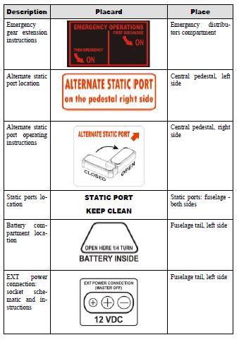
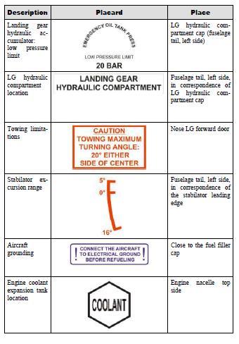
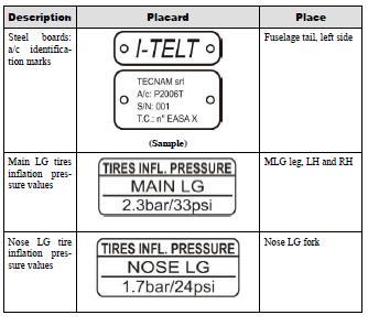
65 PLACARDS 62
66 63
67 64
68 65
69 ELECTRICAL Primary electrical power is provided by two engine-driven alternators which, during normal operations, operate in parallel. Each alternator is rated at Vdc, 40 Amp, and it is fitted with an integrated regulator, which acts to maintain a constant output voltage, and with an automatic overvoltage device protecting the circuits and the electric components from an excessive voltage caused by generator failures. The power rating of each alternator is such that if one alternator fails the other one can still supply the airplane equipment to maintain flight safety. Secondary DC power is provided by a battery (Ship battery) (lead type, Gill Teledyne G35/12V, 38-Amp/hr in 20h run time) and an external DC power source can be connected to the aircraft DC distribution system. Additionally, there is a smaller start battery (Spark 500) which is connected only to the starters via the starter relay. Both batteries are found in the empennage of the aircraft and are placarded on the outside of the aircraft. Starter battery voltage should be check prior to starting the engines by depressing the black button on the voltage indicator located between the pilot and co-pilot seats. (Minimum voltage should be 12 v to start). On the instruments panel, right side, it is installed a voltmeter/ammeter. The ammeter section can indicate the current supplied by either left or right generator switching a dedicated selector. There are five different busses: Battery bus LH Generator bus RH Generator bus LH Avionics bus RH Avionics bus The distribution system operates as a single bus with power being supplied by the battery and both alternators but it is possible to separate the left busses from the right busses when required by means of the Cross Bus switches. All electrical loads are divided among the five busses on the basis of their importance and required power: Equipment with duplicate functions are connected to separate busses. The Battery bus, which supplies the most important loads, is energized from three sources: The battery and both alternators. This allows the bus to remain active also in case of two independent faults in the supply paths.
 via the master switch.")
70 With both engines operating the LH and RH alternators provide power to the battery bus via the LH and RH Cross Bus Switches. Additionally, power is provided to the LH and RH avionics busses via the LH and RH avionics switches. The battery bus supplies power to the Ship Battery (main battery) via the master switch. The Ship Battery will provide power to the Starter Battery via a relay once the Ship Battery has been charged and has reached its proper 12v. The Emergency Battery Switch located on LH circuit breaker pedestal, when used, creates a connection between the Ship Battery and Starter Battery in the event of a single battery failure. The Emergency Battery Switch can be used to start or restart a depleted starter battery, however, once the engines are started, the Emergency Battery Switch must to turned to the off position. Refer to the figure below for details. 66
XIV.C. Flight Principles Engine Inoperative
 XIV.C. Flight Principles Engine Inoperative References: FAA-H-8083-3; POH/AFM Objectives The student should develop knowledge of the elements related to single engine operation. Key Elements Elements Schedule
DUCHESS BE-76 AND COMMERCIAL MULTI ADD-ON ORAL REVIEW FOR CHECKRIDE
 DUCHESS BE-76 AND COMMERCIAL MULTI ADD-ON ORAL REVIEW FOR CHECKRIDE The Critical Engine The critical engine is the engine whose failure would most adversely affect the airplane s performance or handling
Henley Aviation BE-76 Beechcraft Duchess
 The Problem of Asymmetric Thrust When a Multi-engine aircraft with engines not mounted on the longitudinal axis loses an engine, there will be unbalanced forces and turning moments about the center of
Multi-Engine Training Packet
 Multi-Engine Training Packet This multi-engine training course is designed for the Commercial Multi-Engine Rating, MEI and ATP. This packet, in conjunction with the BE-76 Pilot s Operating Handbook contains
Vso 61. Vs1 63. Vr 70. Vx 76. Vxse 78. Vy 89. Vyse. 89 (blue line) Vmc. 61 (radial redline) Vsse 76. Va 134) Vno 163
 Vmc. 61 (radial redline) Vsse 76. Va 134) Vno 163") PA34-200T Piper Seneca II Normal procedures V-speeds Knots Vso 6 Vs 63 Vr 70 Vx 76 Vxse 78 Vy 89 Vyse Vmc 89 (blue line) 6 (radial redline) Vsse 76 Va 2-36(@4507lbs 34) Vno 63 Vfe 38 (0*)/2(25*)/07(40*)
PA34-200T Piper Seneca II Normal procedures V-speeds Knots Vso 6 Vs 63 Vr 70 Vx 76 Vxse 78 Vy 89 Vyse Vmc 89 (blue line) 6 (radial redline) Vsse 76 Va 2-36(@4507lbs 34) Vno 63 Vfe 38 (0*)/2(25*)/07(40*)
Elmendorf Aero Club Aircraft Test
 DO NOT WRITE ON THIS TEST JAN 2014 Elmendorf Aero Club Aircraft Test SENECA II For the following questions, you will need to refer to the Pilots Information Manual for the PA-34-200T. USE ANSWER SHEET
PA34-220T Piper Seneca III
 PREFLIGHT PA34-220T Piper Seneca III Weight and Balance Documents -Airworthiness Certificate -Registration -Airplane Flight Manual -Weight & Balance Hobbs/Time Landing Gear Avionics and Fan(s) Cowl Fuel
INDEX. Preflight Inspection Pages 2-4. Start Up.. Page 5. Take Off. Page 6. Approach to Landing. Pages 7-8. Emergency Procedures..
 INDEX Preflight Inspection Pages 2-4 Start Up.. Page 5 Take Off. Page 6 Approach to Landing. Pages 7-8 Emergency Procedures.. Page 9 Engine Failure Pages 10-13 Propeller Governor Failure Page 14 Fire.
RFC Dallas, Inc. AIRCRAFT QUESTIONNAIRE (9/25/2016) "A Safe Pilot Knows His Equipment"
 A Safe Pilot Knows His Equipment") RFC Dallas, Inc. AIRCRAFT QUESTIONNAIRE (9/25/2016) "A Safe Pilot Knows His Equipment" NAME: Date: Aircraft: Cessna 182Q Registration Number: N631S Serial Number: The purpose of this questionnaire is to
RFC Dallas, Inc. AIRCRAFT QUESTIONNAIRE (9/25/2016) "A Safe Pilot Knows His Equipment" NAME: Date: Aircraft: Cessna 182Q Registration Number: N631S Serial Number: The purpose of this questionnaire is to
FLASHCARDS AIRCRAFT. Courtesy of the Air Safety Institute, a Division of the AOPA Foundation, and made possible by AOPA Services Corporation.
 AIRCRAFT FLASHCARDS Courtesy of the Air Safety Institute, a Division of the AOPA Foundation, and made possible by AOPA Services Corporation. Knowing your aircraft well is essential to safe flying. These
Prop effects (Why we need right thrust) Torque reaction Spiraling Slipstream Asymmetric Loading of the Propeller (P-Factor) Gyroscopic Precession
 Torque reaction Spiraling Slipstream Asymmetric Loading of the Propeller (P-Factor) Gyroscopic Precession") Prop effects (Why we need right thrust) Torque reaction Spiraling Slipstream Asymmetric Loading of the Propeller (P-Factor) Gyroscopic Precession Propeller torque effect Influence of engine torque on aircraft
Prop effects (Why we need right thrust) Torque reaction Spiraling Slipstream Asymmetric Loading of the Propeller (P-Factor) Gyroscopic Precession Propeller torque effect Influence of engine torque on aircraft
Normal T/O Procedure. * * * Engine Failure on T/O * * *
 Normal T/O Procedure After adding full power: Engine Instruments green Airspeed alive 1,000 AGL Accelerate to enroute climb 113 KIAS Set climb power Vr 78, but it will come off the ground before Stay in
Cessna 172P PPL Checklist Page 1
 Cessna 172P PPL Checklist 06-08-2017 Page 1 Cessna 172P PPL Checklist 06-08-2017 Page 2 Checklist Items Informational Items Critical Memory Items PREFLIGHT COCKPIT CHECK (DO-LIST) Pitot Cover -- REMOVE
RFC Dallas, Inc. AIRCRAFT QUESTIONNAIRE (6/3/2018) "A Safe Pilot Knows His Equipment"
 A Safe Pilot Knows His Equipment") RFC Dallas, Inc. AIRCRAFT QUESTIONNAIRE (6/3/2018) "A Safe Pilot Knows His Equipment" NAME: Date: Aircraft: Bonanza Registration Number: Serial Number: The purpose of this questionnaire is to aid the pilot
RFC Dallas, Inc. AIRCRAFT QUESTIONNAIRE (6/3/2018) "A Safe Pilot Knows His Equipment" NAME: Date: Aircraft: Bonanza Registration Number: Serial Number: The purpose of this questionnaire is to aid the pilot
AIRCRAFT FAMILIARIZATION. Some questions may not apply to the aircraft you are flying.
 541-895-5935 Name Date AIRCRAFT FAMILIARIZATION Note: If this information is not provided in the aircraft s flight manual give it your best guess. Some questions may not apply to the aircraft you are flying.
TECNAM P92 EAGLET N615TA TECNAM P92 EAGLET CHECKLIST [FLIGHT PLAN DESIGNATION IS ECHO ]
![TECNAM P92 EAGLET N615TA TECNAM P92 EAGLET CHECKLIST [FLIGHT PLAN DESIGNATION IS ECHO ]](/thumbs/86/93080937.jpg "TECNAM P92 EAGLET N615TA TECNAM P92 EAGLET CHECKLIST [FLIGHT PLAN DESIGNATION IS ECHO ]") TECNAM P92 EAGLET CHECKLIST [FLIGHT PLAN DESIGNATION IS ECHO ] EMERGENCY CONTACT The following are First Landings' emergency contact telephone numbers. We ask that you call the numbers in the order listed.
TECNAM P92 EAGLET CHECKLIST [FLIGHT PLAN DESIGNATION IS ECHO ] EMERGENCY CONTACT The following are First Landings' emergency contact telephone numbers. We ask that you call the numbers in the order listed.
TECNAM P2004 BRAVO N128LS
 TECNAM P2004 BRAVO N128LS GENERAL INFORMATION NORMAL PROCEDURES TIME SENSITIVE EMERGENCY TECNAM P2004 BRAVO CHECKLIST [FLIGHT PLAN DESIGNATION IS BRAV ] EMERGENCY CONTACT The following are First Landings'
Preflight Inspection Cabin EMPENNAGE RIGHT WING Trailing Edge RIGHT WING NOSE
 Preflight Inspection Cabin 1. Control Wheel Lock REMOVED 2. Ignition Switch OFF 3. Avionics Power Switch OFF 4. Master Switch ON 5. Fuel Quantity Indicators CHECK QUANTITY 6. Master Switch OFF 7. Fuel
INDEX: Normal Procedures Emergency Procedures Pre Flight Inspection NORMAL PROCEDURES BEFORE STARTING ENGINE
 INDEX: Normal Procedures Emergency Procedures Pre Flight Inspection NORMAL PROCEDURES BEFORE STARTING ENGINE 1. Preflight Inspection -- COMPLETE 2. Seats, Belts, Shoulder Harnesses -- ADJUST and LOCK 3.
Flight Procedures Aero AT-3 R100
 Flight Procedures Page: 1 1. FOREWORD... 3 2. FLIGHT PREPARATION... 3 3. PRE-FLIGHT CHECK... 3 3.1. External inspection:... 4 3.2. In the cockpit... 4 3.3. Left wing... 5 3.4. Engine nacelle, canopy and
AIR TRACTOR, INC. OLNEY, TEXAS
 TABLE OF CONTENTS LOG OF REVISIONS... 2 DESCRIPTION... 4 SECTION 1 LIMITATIONS... 5 SECTION 2 NORMAL PROCEDURES... 8 SECTION 3 EMERGENCY PROCEDURES... 8 SECTION 4 MANUFACTURER'S SECTION - PERFORMANCE...
GACE Flying Club Aircraft Review Test 2018 N5312S & N5928E. Name: GACE #: Score: Checked by: CFI #:
 GACE Flying Club Aircraft Review Test 2018 N5312S & N5928E Name: GACE #: Score: Checked by: CFI #: Date: (The majority of these questions are for N5312S. All N5928E questions will be marked 28E) 1. What
N1523J CHECKLIST PA Nebraska Flight Center Eppley Airfield 3737 Orville Plaza Omaha, NE Tel. (402)
") CHECKLIST N1523J 1967 Cherokee 140 PA-28-140 F Nebraska Flight Center Eppley Airfield 3737 Orville Plaza Omaha, NE 68110 Tel. (402) 342-4314 www.nebflight.com Piper Cherokee 140 N1523J 1967 GENERAL INFORMATION
CHECKLIST N1523J 1967 Cherokee 140 PA-28-140 F Nebraska Flight Center Eppley Airfield 3737 Orville Plaza Omaha, NE 68110 Tel. (402) 342-4314 www.nebflight.com Piper Cherokee 140 N1523J 1967 GENERAL INFORMATION
Van s Aircraft RV-7A. Pilot s Operating Handbook N585RV
 Van s Aircraft RV-7A Pilot s Operating Handbook N585RV PERFORMANCE SPECIFICATIONS SPAN:..25 0 LENGTH...20 4 HEIGHT:.. 7 10 SPEED: Maximum at Sea Level...180 knots Cruise, 75% Power at 8,000 Ft...170 knots
Owners Manual. Table of Contents 3.1. INTRODUCTION AIRSPEEDS FOR EMERGENCY OPERATION OPERATIONAL CHECKLISTS 3
 EMERGENCY PROCEDURES Table of Contents 3.1. INTRODUCTION 2 3.2. AIRSPEEDS FOR EMERGENCY OPERATION 2 3.3. OPERATIONAL CHECKLISTS 3 3.3.1. ENGINE FAILURES 3. ENGINE FAILURE DURING TAKEOFF RUN 3. ENGINE FAILURE
Gyroplane questions from Rotorcraft Commercial Bank (From Rotorcraft questions that obviously are either gyroplane or not helicopter)
") Page-1 Gyroplane questions from Rotorcraft Commercial Bank (From Rotorcraft questions that obviously are either gyroplane or not helicopter) "X" in front of the answer indicates the likely correct answer.
Page-1 Gyroplane questions from Rotorcraft Commercial Bank (From Rotorcraft questions that obviously are either gyroplane or not helicopter) "X" in front of the answer indicates the likely correct answer.
CHAPTER 11 FLIGHT CONTROLS
 CHAPTER 11 FLIGHT CONTROLS CONTENTS INTRODUCTION -------------------------------------------------------------------------------------------- 3 GENERAL ---------------------------------------------------------------------------------------------------------------------------
Interior Pre Flight Documents: Check Control Wheel Lock: Remove Flight Controls: Check Instruments: Check for Damage Switches: Verify All Off Master
 Interior Pre Flight Documents: Check Control Wheel Lock: Remove Flight Controls: Check Instruments: Check for Damage Switches: Verify All Off Master Switch ALT/BAT: On Fuel Gauge: Check Quantity Flaps:
Performance means how fast will it go? How fast will it climb? How quickly it will take-off and land? How far it will go?
 Performance Concepts Speaker: Randall L. Brookhiser Performance means how fast will it go? How fast will it climb? How quickly it will take-off and land? How far it will go? Let s start with the phase
FLIGHT CONTROLS SYSTEM
 FLIGHT CONTROLS SYSTEM DESCRIPTION Primary flight control of the aircraft is provided by aileron, elevator and rudder control surfaces. The elevator and rudder control surfaces are mechanically operated.
CESSNA 182 CHECKLIST. LEFT WING Trailing Edge 1. Aileron CHECK freedom of movement and security
 CESSNA 182 CHECKLIST PRE-FLIGHT INSPECTION CABIN 1. Pilot s Operating Handbook AVAILABLE IN THE AIRPLANE (A.R.R.O.W.E) 2. Landing Gear Lever DOWN 3. Control Wheel Lock REMOVE 4. Ignition Switch OFF 5.
3. What is the total fuel capacity with normal tanks? Usable? 4. What is the total fuel capacity with long range tanks? Usable?
 Pilot Name: Last, first, mi. Date: (mo/dy/yr) Instructor: Pass/Fail: Instructors Initials: 1. What is the engine Manufacturer: Model: Type: 2. What is the horsepower rating? 3. What is the total fuel capacity
Elmendorf Aero Club Aircraft Test
 DO NOT WRITE ON THIS TEST FEB 2013 Elmendorf Aero Club Aircraft Test Cessna - 182 For the following questions, you will need to refer to the Pilots Information Manual for the C-182R. The bonus questions
Chapter 3: Aircraft Construction
 Chapter 3: Aircraft Construction p. 1-3 1. Aircraft Design, Certification, and Airworthiness 1.1. Replace the letters A, B, C, and D by the appropriate name of aircraft component A: B: C: D: E: 1.2. What
DO NOT WRITE ON THIS TEST FEB 2013 Elmendorf Aero Club Aircraft Test. Cessna - 182
 DO NOT WRITE ON THIS TEST FEB 2013 Elmendorf Aero Club Aircraft Test Cessna - 182 For the following questions, you will need to refer to the Pilots Information Manual for the C-182R. The bonus questions
Elmendorf Aero Club Aircraft Test
 DO NOT WRITE ON THIS TEST FEB 2013 Elmendorf Aero Club Aircraft Test Cessna 172RG For the following questions, you will need to refer to the Pilots Information Manual for the C-172RG and the Auxiliary
PA-28R 201 Piper Arrow
 Beale Aero Club Aircraft Written Test PA-28R 201 Piper Arrow (Required passing score: 80%) 1. If an engine power loss occurs immediately after take off, the pilot s reaction should be to: a. maintain safe
CESSNA 182 TRAINING MANUAL. Trim Control Connections
 Trim Control Connections by D. Bruckert & O. Roud 2006 Page 36 Flaps The flaps are constructed basically the same as the ailerons with the exception of the balance weights and the addition of a formed
Cessna 172 Skyhawk. Aircraft Checklist Models: R & S
 Cessna 172 Skyhawk Aircraft Checklist Models: R & S This is an abbreviated checklist. Most explanatory items, notes cautions and warnings have been omitted for brevity. Procedures in red/bold text in this
Initial / Recurrent Ground Take-Home Self-Test: The Beechcraft 58 Baron Systems, Components and Procedures
 Initial / Recurrent Ground Take-Home Self-Test: The Beechcraft 58 Baron Systems, Components and Procedures Flight Express, Inc. This take-home self-test partially satisfies the recurrent ground training
EGLIN AERO CLUB C-172 OPEN BOOK EXAMINATION Apr Total usable fuel capacity for the aircraft with long range tanks is:
 (The following questions are taken from the C-172N POH) 1. Total usable fuel capacity for the aircraft with long range tanks is: a. 54 gallons b. 50 gallons c. 62 gallons d. 40 gallons 2. Total fuel capacity
PAC 750XL PAC 750XL PAC-750XL
 PAC 750XL The PAC 750XL combines a short take off and landing performance with a large load carrying capability. The PAC 750XL is a distinctive type. Its design philosophy is reflected in the aircraft's
CARENADO COPYRIGHTS. Normal & Emergency Checklist
 NORMAL PROCEDURES CHECKLIST PREFLIGHT CHECK Control wheel -- RELEASE BELTS Avionics -- OFF Master Switch -- ON Fuel quantity gauges -- CHECK Master switch -- OFF Ignition -- OFF Exterior -- CHECK FOR DAMAGE
Introduction. Fuselage/Cockpit
 Introduction The Moravan Zlin 242L is a fully aerobatic 2 seat aircraft designed to perform all advanced flight maneuvers within an envelope of -3.5 to +6 Gs. Many military and civilian flight-training
DEPARTMENT OF TRANSPORTATION FEDERAL AVIATION ADMINISTRATION. TYPE CERTIFICATE DATA SHEET No. A50NM
 DEPARTMENT OF TRANSPORTATION FEDERAL AVIATION ADMINISTRATION A50NM Dassault Aviation Falcon 2000 December 19, 1995 TYPE CERTIFICATE DATA SHEET No. A50NM This data sheet which is part of Type Certificate
This Flight Planning Guide is published for the purpose of providing specific information for evaluating the performance of the Cessna Corvalis TT.
 May 2010 TABLE OF CONTENTS This Flight Planning Guide is published for the purpose of providing specific information for evaluating the performance of the Cessna Corvalis TT. This guide is developed from
DASSAULT AVIATION Proprietary Data
 F900EX EASY 02-27-00 CODDE 1 PAGE 1 / 2 TABLE OF CONTENTS 02-27 02-27-00 TABLE OF CONTENTS 02-27-05 GENERAL Introduction Flight control sources Primary and secondary flight controls 02-27-10 DESCRIPTION
Jump to Table of Contents
 Jump to Table of Contents PIPER AIRCRAFT CORPORATION PA-28R-201, CHEROKEE ARROW III SECTION 3 EMERGENCY PROCEDURES 3.3 EMERGENCY PROCEDURES CHECK LIST ENGINE FIRE DURING
Flightlab Ground School 13. A Selective Summary of Certification Requirements FAR Parts 23 & 25
 Flightlab Ground School 13. A Selective Summary of Certification Requirements FAR Parts 23 & 25 Copyright Flight Emergency & Advanced Maneuvers Training, Inc. dba Flightlab, 2009. All rights reserved.
Aircraft Checklist Commander 114
 Aircraft Checklist Commander 114 This is an abbreviated checklist. Most explanatory items, notes cautions and warnings have been omitted for brevity. Procedures in red/bold text in this checklist should
DA40 Diamond Star Systems Introduction AVIATION
 DA40 Diamond Star Systems Introduction AVIATION DA40 Systems Introduction What we ll look at... Airframe Flight Controls Landing Gear and Hydraulics Engine and Associated Systems Electric and Navigation
CHECKLIST 1969 CESSNA 172-K. NOTE: Verify all information with airplane's POH
 CHECKLIST 1969 CESSNA 172-K NOTE: Verify all information with airplane's POH PRE-FLIGHT INSPECTION 1 CABIN 1 A.R.R.O.W. CHECK Airworthiness Cert. In Clear View Registration In Clear View Radio License
Aircraft Checklist Cessna 182T
 Aircraft Checklist Cessna 182T This is an abbreviated checklist. Most explanatory items, notes cautions and warnings have been omitted for brevity. Procedures in red/bold in this checklist should be committed
CESSNA 172S NAV III VFR CHECKOUT POH EXAMINATION (Based on N1129K, serial no. 172S revised 10/05/06)
") INTRODUCTION, POH CESSNA 172S NAV III VFR CHECKOUT POH EXAMINATION (Based on N1129K, serial no. 172S10315 - revised 10/05/06) 1. Rate of climb at sea level: 2. Service ceiling: 3. Takeoff performance,
INTRODUCTION, POH CESSNA 172S NAV III VFR CHECKOUT POH EXAMINATION (Based on N1129K, serial no. 172S10315 - revised 10/05/06) 1. Rate of climb at sea level: 2. Service ceiling: 3. Takeoff performance,
Systems PA28R-201 ARROW. Engine. Make : Avco Lycoming. Model: IO-360 C1C6. Type:
 1 Systems PA28R-201 ARROW Engine Make : Avco Lycoming Model: Type: IO-360 C1C6 4 cylinders Horizontally opposed Normally aspirated(no turbo charge) Air cooled (Engine oil and fuel helps cooling) Direct
FLIGHT TEST PROGRAM YOUR AIRPLANE HERE FLIGHT TEST PROGRAM YOUR AIRPLANE HERE
 Flight #: 1 FIRST TEST FLIGHT Validate Engine Reliability Explore Flight Control Characteristics Do not use flaps Do not change throttle settings, mixture, or fuel tanks Remain above the airport Climb
XIV.D. Maneuvering with One Engine Inoperative
 References: FAA-H-8083-3; POH/AFM Objectives The student should develop knowledge of the elements related to single engine operation. Key Elements Elements Schedule Equipment IP s Actions SP s Actions
JODEL D.112 INFORMATION MANUAL C-FVOF
 JODEL D.112 INFORMATION MANUAL C-FVOF Table of Contents I General Description...4 Dimensions:...4 Powertrain:...4 Landing gear:...4 Control travel:...4 II Limitations...5 Speed limits:...5 Airpeed indicator
INCORPORA:1EO. PO Box Shannon Lane Priest River, FAA APPROVED
 INCORPORA:1EO FAA APPROVED Document A-1 0023.., Page 1 of. 9 Rev, (see rev. page) SUPPLEMENTAL AIRPLANE FLIGHT MANUAL FOR CESSNA 180J & 180K SERIES FLOATPLANES Modified with Kenmore Air Harbor STC # SA649NW
Best Glide 75 kias (Max Gross)
") CESSNA 172XP CHECKLIST PREFLIGHT (Interior) 1. ACFT DOCS / INSPECTIONS--------CHECK 2. TACH TIME-----------------------------RECORD 3. CONTROL LOCK---------------------REMOVE 4. ELEVATOR / RUDDER TRIM------------
CESSNA 172XP CHECKLIST PREFLIGHT (Interior) 1. ACFT DOCS / INSPECTIONS--------CHECK 2. TACH TIME-----------------------------RECORD 3. CONTROL LOCK---------------------REMOVE 4. ELEVATOR / RUDDER TRIM------------
The Straight Word. Cessna 337 Super Skymaster 337G & T337G Series, and corresponding Reims Aviation models
 The Straight Word Cessna 337 Super Skymaster 337G & T337G Series, and corresponding Reims Aviation models I. FLIGHT PROCEDURES: COCKPIT PREPARATION Heading Bug OBS Indicator Altimeters Trims Parking Brake
Beech 95 Pilot Information Manual
 Beech 95 Pilot Information Manual For the exclusive use of students in the Selkirk College Professional Aviation Program Copyright 2005 revised 2010 Beech 95 POH Effective September 1, 2005 Appendix 14-1
COLUMBIA 350 EMERGENCY PROCEDURES
 COLUMBIA 350 EMERGENCY PROCEDURES TABLE OF CONTENTS EMERGENCY PROCEDURES LANDING AND TAKEOFF Engine Failure During Takeoff...1 Engine Failure Immediately After Takeoff...1 Engine Failure During Climb to
a. Lycoming IO-520J 250 HP c. Lycoming O-540-J3C5D 235 HP b. Continental O450T 330 HP d. Lycoming O-360A 180 HP
 Three points each question Page 1 of 6 References: Pilot's Operating Handbook for the 1979 Cessna R182 Model; Flying Magazine Article "Cessna 182 Safety Report;" RAFA SOP; and Refueling Instructions found
NORMAL PROCEDURRES CHECKLIST PA T SENECA II PREFLIGHT CHECK INSIDE CABIN OUTSIDE CABIN
 NORMAL PROCEDURRES CHECKLIST PA-34-200T SENECA II PREFLIGHT CHECK INSIDE CABIN Avionics Master Switch -- OFF Landing Gear Control. -- DOWN Mixture Controls -- IDLE/CUTOFF Ignition Switches -- OFF Master
The Straight Word. Cessna 337 Skymaster 337C Series. The front engine should always be started first as the battery-to-starter cable is shorter.
 The Straight Word Cessna 337 Skymaster 337C Series I. FLIGHT PROCEDURES: COCKPIT PREPARATION Heading Bug OBS Indicator Altimeters Trims Parking Brake Set QFU Set Course Set QNH Set for Takeoff Apply ENGINE
Aeroplanes DAR ltd. Brief Flight Manual DAR Solo BRIEF FLIGHT MANUAL. DAR-Solo series. Sofia Page 1 of 25
 BRIEF FLIGHT MANUAL DAR-Solo series Sofia 2015 Page 1 of 25 TABLE OF CONTENTS Introduction 3 Limitations and Safety Information 4 General View of DAR-Solo series 6 Ignition 7 Engine warm up 8 Taxiing 9
CHAPTER 2 THE TUTOR. Introduction
 CHAPTER 2 THE TUTOR Introduction 1. AEFs. The Royal Air Force has 12 units throughout the country known as Air Experience flights (AEFs). Their role is to provide air experience flying for cadets and they
AIRSPEEDS. Cessna 172R Emergency Checklist
 AIRSPEEDS AIRSPEEDS FOR EMERGENCY OPERATION Cessna 172R Emergency Checklist INTRODUCTION This document provides checklist and amplified procedures for coping with emergencies that may occur. Emergencies
North American F-86F Sabre USER MANUAL. Virtavia F-86F Sabre DTG Steam Edition Manual Version 1
 North American F-86F Sabre USER MANUAL 0 Introduction The F-86 Sabre was a natural replacement for the F-80 Shooting Star. First introduced in 1949 for the United States Air Force, the F-86 featured excellent
AIRCRAFT GENERAL KNOWLEDGE (1) AIRFRAME/SYSTEMS/POWERPLANT
 AIRFRAME/SYSTEMS/POWERPLANT") 1 In flight, a cantilever wing of an airplane containing fuel undergoes vertical loads which produce a bending moment: A highest at the wing root B equal to the zero -fuel weight multiplied by the span
1 In flight, a cantilever wing of an airplane containing fuel undergoes vertical loads which produce a bending moment: A highest at the wing root B equal to the zero -fuel weight multiplied by the span
Lecture 5 : Static Lateral Stability and Control. or how not to move like a crab. G. Leng, Flight Dynamics, Stability & Control
 Lecture 5 : Static Lateral Stability and Control or how not to move like a crab 1.0 Lateral static stability Lateral static stability refers to the ability of the aircraft to generate a yawing moment to
MULTI ENGINE FLIGHT TRAINING MANUAL PA FTM
 www.theaviatornetwork.com Multi FTM PAGE 1 2011 01-17-2011 MULTI ENGINE FLIGHT TRAINING MANUAL PA-23-160 GRYDER NETWORKS, LLC Dan Gryder, CFII, MEI, ATP, AGI DC-3 DC-9 CE-500 B-757 B-767 B-777 The Herpa
Weight & Balance. Let s Wait & Balance. Chapter Sixteen. Page P1. Excessive Weight and Structural Damage. Center of Gravity
 Page P1 Chapter Sixteen Weight & Balance Let s Wait & Balance Excessive Weight and Structural Damage 1. [P2/1/1] Airplanes are designed to be flown up to a specific maximum weight. A. landing B. gross
Constant Speed Propeller Control
 Constant Speed Propeller Control Overview: An aircraft engine is designed to operate over a relatively small range of revolutions per minute (RPM). This is because propellers are limited by rotational
Test Flying should only be performed by a pilot who is licensed, rated and experienced on the aircraft type.
 Test Flying Procedure: Test Flying should only be performed by a pilot who is licensed, rated and experienced on the aircraft type. In particular, the test pilot should have recently demonstrated an ability
I. DISPATCH PLANNING & AIRCRAFT EXTERIOR CHECK
 SCHODACK AVIATION Page 1 of 10 I. DISPATCH PLANNING & AIRCRAFT EXTERIOR CHECK 1. Flight Planning 1. Aircraft requirements & preparation: Required aircraft documents: Airworthiness Certificate Registration
Embraer Systems Summary [Landing Gear & Brakes]
![Embraer Systems Summary [Landing Gear & Brakes]](/thumbs/87/96901154.jpg "Embraer Systems Summary [Landing Gear & Brakes]") GENERAL DESCRIPTION The airplane has two main landing gears and a single nose gear. Each main gear is a conventional two-wheeled landing gear. The nose gear is a conventional steerable two-wheeled unit.
GENERAL DESCRIPTION The airplane has two main landing gears and a single nose gear. Each main gear is a conventional two-wheeled landing gear. The nose gear is a conventional steerable two-wheeled unit.
S A F E T Y NORMAL PROCEDURES NORMAL PROCEDURES BEFORE STARTING ENGINE PASSENGER SAFETY BRIEFING STARTING ENGINE
 PRE-FLIGHT PRE-FLIGHT BEFORE STARTING ENGINE PASSENGER SAFETY BRIEFING 1. Preflight Inspection COMPLETE 2. Passenger Safety Briefing COMPLETE 3. Seats, Belts, Shoulder Harnesses ADJUST AND LOCK 4. Fuel
European Aviation Safety Agency
 Page 1/8 European Aviation Safety Agency EASA TYPE CERTIFICATE DATA SHEET Cirrus Design SF50 Type Certificate Holder: Cirrus Design Corporation 4515 Taylor Circle Duluth, Minnesota 55811 United States
Airplane Flying Handbook FAA-H A
 Review and Recommendations for Improvement of Airplane Flying Handbook FAA-H-8083-3A Bridging the gap between experimental flight-test and regular flight operations Harry Horlings Experimental Flight Test
N123AX Piper Saratoga II HP (PA-32R-301) Checklist (v23 - Revision 3 April 2011) AIRSPEEDS FOR SAFE OPERATIONS. Best Rate of Climb (gear up, flaps up)
 Checklist (v23 - Revision 3 April 2011) AIRSPEEDS FOR SAFE OPERATIONS. Best Rate of Climb (gear up, flaps up)") N123AX Piper Saratoga II HP (PA-32R-301) Checklist (v23 - Revision 3 April 2011) AIRSPEEDS FOR SAFE OPERATIS Best Rate of Climb (gear down, flaps up) Best Rate of Climb (gear up, flaps up) Turbulent Air
N123AX Piper Saratoga II HP (PA-32R-301) Checklist (v23 - Revision 3 April 2011) AIRSPEEDS FOR SAFE OPERATIS Best Rate of Climb (gear down, flaps up) Best Rate of Climb (gear up, flaps up) Turbulent Air
PREFLIGHT CHECK COCKPIT RIGHT WING. NORMAL PROCEDURRES CHECKLIST PA-28RT 201 Arrow IV
 NORMAL PROCEDURRES CHECKLIST PA-28RT 201 Arrow IV PREFLIGHT CHECK COCKPIT Control Wheel -- Release Restraints Avionics -- OFF Parking Brake -- SET All Switches -- OFF Mixture -- IDLE CUT-OFF Master Switch
CIVIL AVIATION AUTHORITY SAFETY REGULATION GROUP MICROLIGHT TYPE APPROVAL DATA SHEET (TADS) NO: BM65 ISSUE: 6. Flight Design CT2K
 NO: BM65 ISSUE: 6. Flight Design CT2K") TYPE: Flight Design CT2K (1) MANUFACTURER: P&M Aviation Ltd, Unit B, Crawford St, Rochdale. (UK type approval holder for Flight Design GMBH) (2) UK IMPORTER: P&M Aviation Ltd. (3) CERTIFICATION: BCAR section
TYPE: Flight Design CT2K (1) MANUFACTURER: P&M Aviation Ltd, Unit B, Crawford St, Rochdale. (UK type approval holder for Flight Design GMBH) (2) UK IMPORTER: P&M Aviation Ltd. (3) CERTIFICATION: BCAR section
System Normal Secondary Direct. All 3 PFC work in parallel. available. Pitch Normal Secondary Direct. Pitch maneuver command.
 Flight s System Normal Secondary Direct Primary Flight Computers (PFC) Three Primary Flight Computers use control wheel and pedal inputs from the pilot to electronically the primary flight control surfaces
The engines are designed to use 100/130 octane fuel. If not available use next higher grade. - 1
 PNEUMATIC SYSTEM The aircraft has a dual pneumatic system. In case of failure of either pneumatic pump, the system will automatically select the operative source. (Inoperative source will be indicated
T-51 Mustang - 3/4 Scale Kit
 T-51 Mustang - 3/4 Scale Kit Description Titan Aircraft is pleased to offer the T-51D Mustang. This P-51D replica incorporates material and systems not commonly found in comparably priced aircraft. This,
The Straight Word. Cessna 208 Caravan 208 Caravan I & 208B Grand Caravan Series
 The Straight Word Cessna 208 Caravan 208 Caravan I & 208B Grand Caravan Series I. FLIGHT PROCEDURES: COCKPIT PREPARATION Fuel Tank Selectors Ignition Switch Heading Bug HSI Course Indicator Altimeters
Van s Aircraft RV-4. Pilot s Operating Handbook
 Van s Aircraft RV-4 Pilot s Operating Handbook PERFORMANCE SPECIFICATIONS SPAN:.. 23 0 LENGTH:. 19 9 HEIGHT:. 6 8 SPEED: Maximum at Sea Level.. Cruise, 75% Power at 8,000 Ft.. 173 Knots 165 Knots RANGE
TYPE-CERTIFICATE DATA SHEET
 TYPE-CERTIFICATE DATA SHEET NO. EASA.A.610 for Type Certificate Holder Game Composites Ltd. Ground Floor Flat 56 Queen s Gate, London, SW7 5JW, United Kingdom For models: TE.CERT.00048-001 European Aviation
M20J-201 Checklist BEFORE STARTING ENGINE
 M20J-201 Checklist BEFORE STARTING ENGINE Preflight... COMPLETE Baggage door... LATCHED/LOCKED Door... LATCHED/LOCKED Seatbelts... FASTENED Passenger brief....... [seatbelts/exits/smoking/talking/traffic]
Piper Archer II (PA )
") 1. Oil... 6-8 qts, Cap Secure CABIN 1. POH & Documents.. Check Available 2. Magneto Switch...... OFF 3. Pitot/Static Drains... Push to Drain 4. Avionics/Electrical Switches... OFF 5. Master Switch. ON
1. Oil... 6-8 qts, Cap Secure CABIN 1. POH & Documents.. Check Available 2. Magneto Switch...... OFF 3. Pitot/Static Drains... Push to Drain 4. Avionics/Electrical Switches... OFF 5. Master Switch. ON
Liberty Aerospace, Inc. Section 1 SECTION 1 GENERAL TABLE OF CONTENTS
 Liberty Aerospace, Inc. Section 1 SECTION 1 TABLE OF CONTENTS Introduction... 1-3 Airplane Three Views... 1-4 Descriptive Data... 1-5 Engine... 1-5 Propeller... 1-5 Fuel... 1-5 Oil... 1-5 Maximum Certificated
Design Considerations for Stability: Civil Aircraft
 Design Considerations for Stability: Civil Aircraft From the discussion on aircraft behavior in a small disturbance, it is clear that both aircraft geometry and mass distribution are important in the design
Boeing B-47 Stratojet USER MANUAL. Virtavia B-47E Stratojet DTG Steam Edition Manual Version 2
 Boeing B-47 Stratojet USER MANUAL 0 Introduction The Boeing B-47 was the first swept-wing multi-engine bomber in service with the USAF. It was truly a quantum leap in aviation history, and is the forerunner
DASSAULT AVIATION Proprietary Data
 F2000EX EASY 02-27-00 CODDE 1 PAGE 1 / 2 TABLE OF CONTENTS 02-27 02-27-00 TABLE OF CONTENTS 02-27-05 GENERAL Introduction Flight control sources Primary and secondary flight controls 02-27-10 DESCRIPTION
Hawker Beechcraft Corporation on March 26, 2007
 DEPARTMENT OF TRANSPORTATION FEDERAL AVIATION ADMINISTRATION A00010WI Revision 8 Hawker Beechcraft 390 March 26, 2007 TYPE CERTIFICATE DATA SHEET NO. A00010WI This data sheet, which is part of Type Certificate
CIVIL AVIATION AUTHORITY SAFETY REGULATION GROUP MICROLIGHT TYPE APPROVAL DATA SHEET (TADS) NO: BM 55 ISSUE: 6
 NO: BM 55 ISSUE: 6") TYPE: Shadow Series D & DD (1) MANUFACTURER CFM Aircraft Ltd (ceased trading) BMAA is responsible for continued airworthiness (2) UK IMPORTER None (3) CERTIFICATION BCAR Section S (First example Issue
TYPE: Shadow Series D & DD (1) MANUFACTURER CFM Aircraft Ltd (ceased trading) BMAA is responsible for continued airworthiness (2) UK IMPORTER None (3) CERTIFICATION BCAR Section S (First example Issue
Tie down IAS-TAS Table 14
 PA28-161- 1 Piper PA28-161 Archer II Cockpit Interior Exterior Check Exterior Check [cont.] Before Start Engine Start After Start ENG Flooded Start Start with External Pwr Run-Up Before Takeoff Short Field
Shadow Series D & DD
 Shadow Series D & DD 1 MANUFACTURER CFM Aircraft Ltd (ceased trading) BMAA is responsible for continued airworthiness 2 UK IMPORTER None 3 CERTIFICATION BCAR Section S (First example Issue 1 dated April