One Year Limited Warranty. FCC Part 15 Class B Registration Warning
|
|
|
- Elijah Nash
- 6 years ago
- Views:
Transcription
1
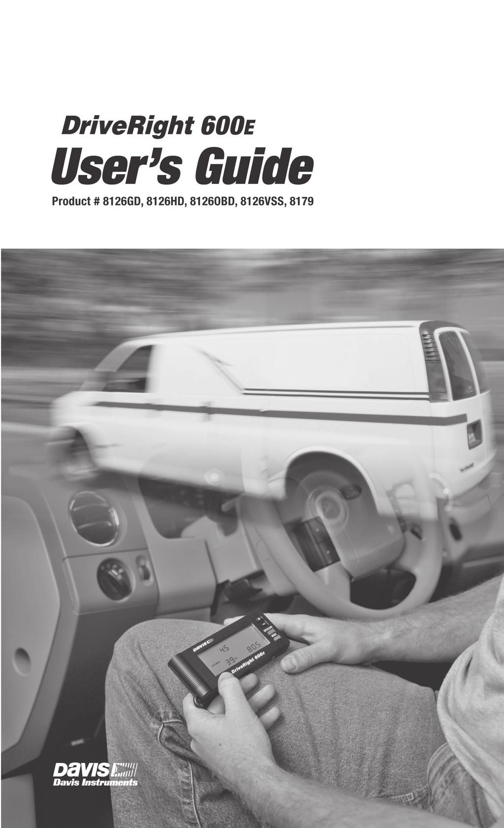
2 One Year Limited Warranty We warrant our products to be free of defects in material and workmanship for one year from date of original purchase. We make every effort to carefully manufacture our products to the highest standards of quality. Occasionally, however, parts may be missing, defective, or damaged. If you have a defective part, please call for authorization before returning the item for repair or replacement. Upon receiving authorization, return the product to us, shipping charges prepaid. Include proof of purchase and a written explanation of the problem. During the warranty period, we will, at our option, either repair or replace the product free of charge. This warranty does not cover damage due to improper installation or use, negligence, accident, unauthorized service, or the incidental or consequential damages beyond the Davis products themselves. Implied warranties are limited in duration to the life of this limited warranty. Some states do not allow limitations on how long an implied warranty lasts, or the exclusion or limitation of incidental and consequential damages, so the above limitations may not apply to you. This warranty gives you specific legal rights. You may have other rights, which vary from state to state. FCC Part 15 Class B Registration Warning This equipment has been tested and found to comply with the limits for a Class B digital device, pursuant to Part 15 of the FCC Rules. These limits are designed to provide reasonable protection against harmful interference in a residential installation. This equipment generates, uses, and can radiate radio frequency energy and, if not installed and used in accordance with the instructions, may cause harmful interference to radio communications. However, there is no guarantee that interference will not occur in a particular installation. If this equipment does cause harmful interference to radio or television reception, which can be determined by turning the equipment on and off, the user is encouraged to try to correct the interference by one or more of the following measures: Reorient or relocate the receiving antenna. Increase the separation between the equipment and receiver. Connect the equipment into an outlet on a circuit different from that to which the receiver is connected. Consult the dealer or an experienced radio/tv technician for help. Changes or modifications not expressly approved in writing by Davis Instruments may void the user's authority to operate this equipment. Davis Instruments Corp All rights reserved. DriveRight 600E User s Guide Rev. B, 5/31/07 Document Part Number: Product Numbers: 8126GD, 8126HD, 8126VSS, 8126OBD, 8179 The information in this manual is subject to change without notice. This product complies with the essential protection requirements of the EC EMC Directive 89/336/EC and 95/54/EC e Mark. DriveRight is a registered trademark of Davis Instruments Corp Diablo Avenue, Hayward, CA U.S.A Fax: info@davisnet.com
3 Table of Contents Introduction to the DriveRight 600E A Note About the Concept of Trips... 1 DriveRight Fleet Management Software... 1 Using the DriveRight 600E... 2 Using the Four Buttons... 2 DriveRight 600E Screens... 2 Data Screens... 3 Settings Screens... 3 Calibrating the DriveRight 600E... 4 Calibrating the DriveRight 600E using FMS... 5 Calibrating Using the Speedometer... 5 Calibrating Using Distance Readings... 7 Data Screens... 8 Current Readings Screen... 9 Driver ID Code Entry & Digital Input Status Screen Trip Start/End Log Screen...11 Trip Speed and Distance Log Screen Trip Acceleration/Deceleration Log Screen GPS Latitude and Longitude Position Screens Limits Screen Settings Screens Security Code Screen Clear Log Screen Alarm On/Off Screen Calibration Screen Time Entry Date Entry Year Entry Miscellaneous Information Accident Log Tamper Log Battery Operation Battery Life Display Lamp Restarting the DriveRight 600E Troubleshooting Guide Technical Specifications Contacting Davis Technical Support i
4 ii
5 Introduction to the DriveRight 600E The DriveRight 600E, in conjunction with DriveRight Fleet Management Software (FMS), provides advanced vehicle safety and monitoring capabilities as well as comprehensive fleet management capabilities. This manual explains how to use the DriveRight 600E to view information and change DriveRight 600E settings. A Note About the Concept of Trips Much of the data stored and displayed by the DriveRight 600E is stored by trip. A trip is the time that has elapsed from when the vehicle first moves to the time the DriveRight 600E device logs a trip stop time or a driver logs out. For example, the maximum speed and the time spent driving over the set speed limit can be viewed for each trip. Stored in the DriveRight 600E is a trip stop time, which represents the amount of time for which the vehicle must be stopped before the DriveRight 600E ends the current trip. The default trip stop time is 10 minutes (this setting may be altered using FMS). Whenever the vehicle is not in motion for an amount of time equal to the trip stop time, the DriveRight 600E saves the current trip data to memory and begins a new trip (this new trip remains empty until the vehicle begins moving again). The DriveRight 600E also saves the current trip data whenever a driver logs out (see Driver ID Code Entry & Digital Input Status Screen on page 10). DriveRight Fleet Management Software DriveRight Fleet Management Software (FMS) enables a user to keep track of detailed vehicle information, and provides access to some additional features in the DriveRight 600E device. The following is a list of the DriveRight 600E features which are accessed by using FMS only. View information contained in the accident log View tamper information Set login alarm Set trip stop time Download up to 100 authorized driver ID codes Set and revise limit settings View trip type information Although you may specify the type of trip using the DriveRight 600E display device, you must have FMS to view trip type information. Configure GPS Requires optional DriveRight 600E GPS/Wireless Interface Module (# 8127) and GPS Module (# 8128). 1
6 Using the DriveRight 600E Using the DriveRight 600E This section briefly describes the DriveRight 600E display, the use of the four buttons (PLUS, MINUS, MODE, SET/CLEAR) and the sequence of Data Screens and Settings Screens. Descriptions of the information and options available from each screen are explained separately in Data Screens starting on page 8 and Settings Screens starting on page 15. Note: Never attempt to change the DriveRight 600E display while driving. Safe driving requires extreme attentiveness. Changing the DriveRight 600E display while driving may result in dangerous distraction. Only use the device when you are not operating your vehicle. Always warn drivers about the DriveRight 600E s alarms. If an alarm sounds, a driver who has not been warned may be startled or get distracted trying to trace the source of the noise. In either case, it may create a safety concern, so warn drivers in advance. Using the Four Buttons The DriveRight 600E has four buttons: PLUS, MINUS, SET/CLEAR, and MODE. The general use of each button is explained briefly below: PLUS (+) and MINUS (-) Use PLUS and MINUS to toggle options On or Off, or to scroll through the ten digits possible (0-9) when entering a number (usually for entering or setting the Driver ID code, or changing the date and time). Also, use PLUS and MINUS to page forward or backward (respectively) through the stored trips or logs. SET/CLEAR When entering codes, the flashing digit/segment indicates what will change if PLUS or MINUS is pressed. Pressing and releasing SET/CLEAR causes the next digit/segment to flash. From the Driver ID Code Screen, press and hold SET/CLEAR (for at least 2 seconds) to log out. The Driver ID code is reset to In the Current Readings Screen, press and hold SET/CLEAR for 2 seconds to toggle between the two available units of measure (mph and km). In the Date Entry and Time Entry Screens, press SET/CLEAR until the entry flashes and use PLUS and MINUS to scroll through the options. MODE Press and release MODE to move to the next data or information screen. Press and hold MODE to switch between the Data Screens and the Settings Screens. When the DriveRight 600E is in sleep mode, press MODE to wake it up. DriveRight 600E Screens The DriveRight 600E contains several screens for viewing and navigating the stored data (Data Screens) and screens for changing and updating the DriveRight 600E settings (Setting Screens). 2
7 DriveRight 600E Screens Data Screens The Data Screens display most of the information stored in the DriveRight 600E device. To cycle through the Data Screens (in the order shown below), press and release MODE several times. The GPS Latitude and Longitude Screens are not displayed if the DriveRight 600E device is not connected to a vehicle with a corresponding GPS module or if the device has not been configured to log GPS data via FMS. Settings Screens DriveRight 600E Data Screens Press and hold MODE in any of the Data Screens to view the Settings Screens. After a few seconds, the Security Code Screen displays. To cycle through the settings screens (in the order shown on the following page), press and release MODE. 3
8 Calibrating the DriveRight 600E Note: To exit the Settings Screens and view the Data Screens, press and hold MODE until the Current Readings Screen displays. CODE CLEAR LOG Security Code (First Screen) Clear Log YEAR ALARM Year Entry Alarm On/Off DAY.MO SPEED km/h Km Date Entry Calibration AM Time Entry DriveRight 600E Settings Screens Calibrating the DriveRight 600E Once the DriveRight 600E is installed in a vehicle, calibrate the device so that it reports the correct speed, distance, deceleration, and acceleration. All General Duty and Heavy Duty (# 8126GD and # 8126HD) versions of DriveRight 600E should be calibrated using the speedometer (see Calibrating Using the Speedometer on page 5), or by using the distance reading (see Calibrating Using Distance Readings on page 7). The VSS (vehicle speed sensor) version (# 8126VSS) of the DriveRight 600E should be calibrated if the vehicle s VSS pulses per mile is different 4
9 Calibrating the DriveRight 600E from the DriveRight 600E s default of 4000 pulses per mile, or if the vehicle s pulses per mile are not known. VSS versions should be calibrated using the speedometer (see Calibrating Using the Speedometer on page 5), or by using the distance reading (see Calibrating Using Distance Readings on page 7) or, if the vehicle s pulses per mile reading is known, can be calibrated using FMS. DriveRight 600E OBD (# 8126OBD) requires no calibration because it is installed in the vehicle s On-Board Diagnostic (OBD) port. Select the OBD installation method when you add a DriveRight 600E OBD to DriveRight FMS. Note: Enter the security code before calibrating the DriveRight 600E. See Security Code Screen on page 16 for more information. Calibrating the DriveRight 600E using FMS Use FMS to accurately calibrate the DriveRight 600E VSS device, provided you know the pulses per mile used by your vehicle s VSS (vehicle speed sensor). Contact your dealer s service department for the pulses per mile used by your vehicle s VSS. Instructions on calibrating the DriveRight 600E using FMS can be found in the FMS Online Help. Calibrating Using the Speedometer To calibrate using the DriveRight 600E s speedometer, drive steadily at 40 km/h (25 mph) and press SET/CLEAR on the DriveRight 600E. The DriveRight 600E bases its calibration on the speed of the vehicle at the moment of calibration which it assumes to be 40 km/h (25 mph). Because of the nature of this calibration procedure, Davis Instruments strongly recommends that it be performed by two people: one to drive the vehicle and one to operate the DriveRight 600E. Note: If the security code is protected, enter the code number. The Calibration Screens can not be accessed until the security code is entered. 1. Press and hold MODE to access the Settings Screens. 2. Enter the security code in the Security Code Screen. 3. Press and release MODE until the Calibration Screen displays. The calibration speed (40 or 25) is located at the bottom right of the display. The uncalibrated speed reading is located at the top of the display, along with the unit of measure (km/h or mph). Until the DriveRight 600E is calibrated, this speed reading will be inaccurate. The distance, which appears in the lower left of the display, is not necessary for this calibration procedure. 5
10 Calibrating the DriveRight 600E Speed Reading SPEED DISTANCE MILES Km MPH km/h Distance Reading Calibration Speed Calibration Screen 4. Drive the vehicle until it reaches 40 km/h (25 mph) and keep the vehicle steady at that speed. 5. Press and hold SET/CLEAR once the vehicle is moving steadily at the calibration speed. The word CAL appears in the top right of the display. This indicates that the DriveRight 600E is in the process of calibrating. Unit Calibrating SPEED DISTANCE km/h Km Unit Calibrating 6. Continue to hold SET/CLEAR until the DriveRight 600E beeps and the word DONE appears on the display. The DriveRight 600E has finished calibrating. The speed reading at the top of the display also changes so that it reads closer to the vehicle s speedometer reading. Unit Finished Calibrating SPEED DISTANCE km/h Km Unit Finished Calibrating 7. Once the calibration is complete, drive the vehicle and compare the vehicle s speedometer to the DriveRight 600E s speed display. 6
11 Calibrating the DriveRight 600E Be aware that the DriveRight 600E responds to changes in speed faster than most vehicles speedometers. To accurately compare, drive steadily at one speed for a short time. 8. Fine tune the calibration by pressing PLUS or MINUS. Each time PLUS or MINUS is pressed, the DriveRight 600E speed reading adjusts up or down. Depending on the speed of the vehicle and the calibration, a change in the speed reading in the Calibration Screen may or may not display each time a button is pressed. Note: Pressing and holding PLUS or MINUS increases the rate at which the DriveRight 600E adjusts the speed reading. 9. Continue to press PLUS or MINUS until the DriveRight 600E s speed reading agrees with the vehicle s speedometer at a variety of speeds. 10. When you are finished calibrating, press and hold MODE until the Current Readings Screen displays. All calibration information is automatically saved. Note: Do not press and hold SET/CLEAR in an effort to save the fine-tuned calibration. The DriveRight 600E resets the calibration number if SET/CLEAR is pressed. Calibrating Using Distance Readings To calibrate using the vehicle s distance reading instead of its speed readings, compare a distance reading taken from the vehicle s odometer to the DriveRight 600E distance reading and adjust the DriveRight 600E to match the vehicle s odometer. Note: Davis Instruments recommends that you drive a minimum of 32km (20 miles) when calibrating the DriveRight 600E using its distance reading. The vehicle s speedometer and odometer may not be perfectly linked. If the two readings differ and the DriveRight 600E has been calibrated using the vehicle s odometer, a discrepancy between the DriveRight 600E s speed readings and the vehicle s speedometer may exist. 1. Obtain a rough calibration, using the speedometer as described in Calibrating Using the Speedometer on page Reset the vehicle s trip meter to zero or note the odometer reading. 3. Start a new trip on the DriveRight 600E (i.e., the distance traveled is 0) and make sure the Current Readings Screen is being displayed. To forcibly start a new trip, log out (see page 11 for details). 4. Drive the vehicle for at least 32 km (20 miles). The calibration becomes more accurate the further the vehicle is driven. 7
12 Data Screens 5. When finished driving, compare the vehicle s distance reading to the distance reading on the DriveRight 600E. 6. Increase or decrease the distance measured by the DriveRight 600E until it agrees with the vehicle s odometer reading. This is accomplished from the Calibration Screen. 7. Press and hold MODE to access the Settings Screens. 8. Press and release MODE until the Calibration Screen displays. The distance traveled appears at the lower left of the display. Note that until the DriveRight 600E is calibrated, this distance reading is inaccurate. The speed reading and calibration speed, which appear on the display as well, are not necessary for this calibration process. Speed Reading SPEED DISTANCE MPH km/h MILES Km Distance Reading Calibration Speed Calibration Screen 9. Press PLUS or MINUS until the distance reading matches the distance on the vehicle. Note: Pressing and holding PLUS or MINUS increases the rate at which the DriveRight 600E adjusts the distance reading. 10. When finished calibrating, press and hold MODE until the Current Readings Screen displays. All calibration information is automatically saved. Note: Do not press and hold SET/CLEAR in an effort to save the fine-tuned calibration. The DriveRight 600E completely resets the calibration number if SET/CLEAR is pressed. Data Screens The following section explains all the information and options available in the Data Screens. In addition to the options listed in the individual sections below, the following two options are available in every screen: Move to the next Data Screen Press and release MODE. View the Settings Screens Press and hold MODE. 8
13 Current Readings Screen Data Screens The Current Readings Screen display is constantly updating (when the vehicle is moving) speed, distance (for the current trip), and acceleration/deceleration readings (acceleration is positive, deceleration is negative). The current date (or time) is also displayed on this screen. Current Speed CURRENT SPEED km/h Date (or Time) DAY.MO DISTANCE ACCEL Km G Distance Traveled on Current Trip Current Acceleration (or Deceleration) Current Readings Screen The following options are available in the Current Readings Screen: Toggle Between Date and Time Display To display either the date or the time, press and release SET/CLEAR. Change Units of Measure Displayed To change the units of measure in which the data is displayed from metric to U.S. units (or vice versa), press and hold SET/CLEAR for approximately 2 seconds. This does not change the date or time display format. Specify Trip Type There are four types of trips stored by the DriveRight 600E: Business, Personal, Commute, and Other. The trip type is stored along with the rest of the trip information and is automatically saved when information is downloaded using FMS. To change the type of trip, press and hold MINUS. The Trip Type Screen displays and scrolls through the four options. Do not release MINUS. The DriveRight 600E scrolls through the letters representing the various trip types: b = Business, P = Personal, C = Commute, O = Other. Release MINUS when the desired trip type displays. The trip type can be changed anytime during the trip. Trip type information is saved when the trip ends. MILES Trip Type Screen 9
14 Data Screens Note: Although trip type can be specified using the DriveRight 600E display device, FMS must be used to view the trip type for each trip. Turn Display Lamp On/Off To turn the DriveRight 600E s display lamp on or off, press PLUS. View the Current Readings Screen, or the GPS Screen to turn the display lamp on and off. Note: The lamp does not turn off if the vehicle is in motion. The lamp automatically turns off once the log out time has elapsed. Driver ID Code Entry & Digital Input Status Screen Enter the Driver ID Code in the Driver ID Code Entry Screen to display the status of the two digital inputs, and view an activity indicator for the reed switch (GD and HD models) or VSS input (VSS model). Activity Indicator Driver ID CODE Digital Input 1 Digital Input 2 Driver ID Code Entry Screen Driver ID Code When using the DriveRight 600E to monitor multiple drivers, assign each driver a unique 4-digit ID code. Before driving the vehicle, the driver must enter his or her ID code. Manual entry of the Driver ID can be disabled using FMS if the SmartCard On-Board Reader (#8105) is being used to log drivers in and out of the vehicle. The DriveRight 600E stores the Driver ID Code with the rest of the trip information. Data downloaded to FMS is segregated by Driver ID Code, enabling detailed tracking of multiple drivers. If the Driver ID Code is set for a single user, Location IDs can be identified using FMS (see FMS Online Help for more information). Also, use FMS to turn on an alarm which will alert the driver when a Driver ID (or Location ID) has not been entered. 10
15 Data Screens Note: Driver ID code 0000 (four zeros) is used to view information for the vehicle (all drivers) and should not be assigned to any driver. In addition to marking data as belonging to a particular driver, the Driver ID code may be used on the device to filter the information being viewed. To view information for one specific driver, enter that Driver s ID code in this screen. The DriveRight 600E display filters out any data not assigned to that code. To view all information, regardless of Driver ID Code, enter The following options are available in the Driver ID Code Entry Screen: Enter a Driver ID Code When the Driver ID Code Entry Screen is first displayed, the first digit to the left flashes, indicating that it is the active digit. Press and release PLUS or MINUS to cycle forward or backward through the available entries for the active digit (0 to 9). To change the digit which is active, press and release SET/CLEAR. The digits are cycled through each time SET/CLEAR is pressed. Only the Driver ID codes that have been programmed into the DriveRight 600E are accepted. A NO displays on the screen if a wrong ID code is entered. A code of 0000 is still accepted. Log Out Press and hold SET/CLEAR for 2 seconds, until the code resets to As soon as a driver logs out, the current trip is ended and data for that trip is stored in the DriveRight 600E s memory. Do not log out when the vehicle is in motion. Two Digital Inputs Two digital inputs are available on the DriveRight 600E that track the operation of lights or other electrically powered accessories on the vehicle. A typical application would be to monitor the headlights and the brakes. The screen displays 1 if the input is high, and 0 if the input is low. The status of the inputs is stored in the trip log. Activity Indicator Primarily useful for troubleshooting the installation, the small dot between the two activity indicators displays whenever the reed switch used with the General Duty (# 8126GD) and Heavy Duty (# 8126HD) models is closed, or whenever the VSS input used with the VSS (# 8126VSS) model is high. The reed switch closes once each time the vehicle s drive shaft rotates. Trip Start/End Log Screen The Trip Start/End Log Screen shows the start and end time for each trip currently stored in the DriveRight 600E s memory. To view trip times for a specific driver, enter that driver s ID code in the Driver ID 11
16 Data Screens Code Entry Screen. To view all trip times for the vehicle, enter ID code Note: If the end time for a trip is dashed, it means that the current trip is being viewed, which has not yet ended (unless it was restarted in the middle of a trip).. Trip Start Time Date START LOG END PM PM TOTAL DAY.MO Hr. Trip End Time Trip Duration Trip Start/End Log Screen The following option is available in the Trip Start/End Log Screen: Page Through Stored Trip Information Press MINUS to page backward through stored trip information. Press PLUS to page forward through stored trip information. Hold the button to increase the paging speed. The DriveRight 600E stops paging in the selected direction once it reaches the first or last trip. Trip Speed and Distance Log Screen The Trip Speed and Distance Log Screen shows the maximum speed, distance traveled, and amount of time spent driving over the set speed limit for each trip currently stored in the DriveRight 600E s memory. To view trip speed and distance information for a specific driver, enter that driver s ID code in the Driver ID Code Entry Screen. To view all trip speed and distance information for the vehicle, enter Driver ID Code
17 Data Screens Maximum Speed During Trip Date SPEED LOG DISTANCE MAXIMUM Km km/h TIME OVER SPEED DAY.MO Sec. Distance Traveled During Trip Amount of Time Spent Driving Over Set Speed Limit During Trip Trip Speed and Distance Log Screen The following option is available in the Trip Speed and Distance Log Screen: Page Through Stored Trip Information Press MINUS to page backward or press PLUS to page forward through stored trip information. Hold either button down to increase the paging speed. The DriveRight 600E stops paging in the selected direction once it reaches the first or last trip. Trip Acceleration/Deceleration Log Screen The Trip Acceleration/Deceleration Log Screen shows the number of times the set acceleration and deceleration limits were exceeded during each trip currently stored in the DriveRight 600E s memory. Each time the limit is exceeded, one count is recorded, regardless of the amount of time the limit was exceeded. To view trip acceleration/deceleration information for a specific driver, enter that driver s ID code in the Driver ID Code Entry Screen. To view all trip acceleration/deceleration information for the vehicle, enter ID code Date DAY.MO LOG DECEL COUNT ACCEL COUNT Number of Times Deceleration Limit Exceeded During Trip Number of Times Acceleration Limit Exceeded During Trip Trip Acceleration/Deceleration Log Screen 13
18 Data Screens The following options are available in the Trip Acceleration/Deceleration Log Screen: Page Through Stored Trip Information Press MINUS to page backward through stored trip information. Press PLUS to page forward through stored trip information. Hold the button to increase the paging speed. The DriveRight 600E stops paging in the selected direction once it reaches the first or last trip. GPS Latitude and Longitude Position Screens The GPS Position Screens alternate between Latitude and Longitude to show the vehicle s current position, speed, and direction. Note: The GPS Screens are not displayed if the DriveRight 600E is not connected to a vehicle with a corresponding GPS module or if the device has not been configured to log GPS data via FMS. Whole Degrees Latitude Decimal Degrees Latitude Current Direction GPS Latitude Latitude Screen Whole Degrees Longitude Decimal Degrees Longitude Current Speed Longitude Screen Longitude 14
19 Settings Screens A NO on the Latitude and Longitude Screens indicates the GPS module is not able to track your current position. The last known position is displayed. NO Not Tracking Not Tracking Indicator Note: The GPS may take up to several minutes to start tracking a new trip, depending on the overhead obstructions near the vehicle. Limits Screen The Limits Screen displays the set speed, acceleration, and deceleration limits for the DriveRight 600E. None of the limits can be changed from this screen. The limits can only be changed using FMS. Acceleration and deceleration are measured in factors of G (the gravitational constant which represents the acceleration of an object when falling to earth in a vacuum). 1G is roughly equal to an acceleration of 35 km/h (22 mph) per second. Speed Limit SPEED DECEL km/h ACCEL G G Deceleration Limit Acceleration Limit Settings Screens Limits Screen The following section explains all the information and options available in the various Settings Screens. In addition to the options listed in the individual sections below, the following two options are available in every screen: 15
20 Settings Screens Move to the next Settings Screen Press and release MODE. View the Data Screens Press and hold MODE. Security Code Screen If you are concerned about unauthorized changing of DriveRight 600E settings, enter a security code set either in the DriveRight 600E itself or in DriveRight FMS. After entering the security code, the DriveRight 600E does not allow access to the rest of the Settings Screens until the correct 4- digit security code is entered. Five attempts are allowed to enter the correct security code before returning to the Current Readings Screen and activating the tamper indicator (pressing MODE to move to the next Settings Screen is considered an attempt ). The time and date of the unsuccessful tamper attempt are stored and may be viewed using FMS. Note: Use security code 0000 (four zeros) to keep the settings and calibration from being password-protected, since the DriveRight 600E defaults to that code when first displaying the Security Code Screen. CODE Security Code Screen The following options are available from the Security Code Screen: Enter the Security Code The flashing digit in the code is the active digit. Press and release PLUS or MINUS to cycle forward or backward through the available entries for the active digit (0 to 9). To change the active digit, press and release SET/CLEAR. Each time SET/CLEAR is pressed, the next digit becomes active. Once the correct security code has been entered, press MODE to move to the next Setting Screen. Note: If the entered code is correct, the Clear Log Screen displays. If the entered code is not correct, the word NO displays. The correct code may be attempted five times before the DriveRight 600E returns to the Current Readings Screen and activates the tamper indicator, if the tamper indicator is enabled. See the FMS Online Help for more information. 16
21 Settings Screens Set or Change the Security Code Use PLUS and MINUS to enter the current correct code, if entering the security code for the first time, make sure 0000 is entered. Press and hold SET/ CLEAR until CHG (change) displays. CODE Change Security Code Use PLUS and MINUS to enter the new desired security code and make a note of the new security code. When finished, press MODE to save the new code and move to the Clear Log Screen. Clear Log Screen The Clear Log Screen may be used to perform a total clear function which erases all data for every trip in your log at once. Note: All the stored trips for every driver are cleared using this screen. CLEAR LOG Clear Log Screen Note: Accident and tamper log data cannot be cleared using this screen. The following option is available in the Clear Log Screen: Clear all Log Data Press and hold SET/CLEAR. The word CLR (clear) appears in the display to indicate that the DriveRight 600E is preparing to clear all log data. To protect against accidental clearing of data, press and hold SET/CLEAR for 3 seconds to clear the data. 17
22 Settings Screens CLEAR LOG Preparing to Clear Log Data Continue to hold SET/CLEAR until the DriveRight 600E beeps and CLR disappears from the display. This indicates that the DriveRight is in the process of clearing data. The DriveRight beeps and DONE appears in the display when the DriveRight finishes clearing data. CLEAR LOG Alarm On/Off Screen DriveRight Finished Clearing Data The Alarm On/Off Screen toggles the DriveRight 600E s audible alarm on and off. When the alarm is on, the DriveRight 600E beeps when any of the set limits are exceeded, warning the driver of the violation. Turning the alarm off disables the beeping, though the DriveRight 600E continues to record violations of the set limits. ALARM Alarm On/Off Screen The following option is available in the Alarm On/Off Screen: Toggle the Alarm Setting Press and release SET/CLEAR to toggle the alarm setting from On to Off (or vice versa). Each time SET/ CLEAR is pressed, the display changes between ON and OFF. Calibration Screen The Calibration Screen calibrates the DriveRight 600E for the desired vehicle. See Calibrating the DriveRight 600E on page 4 for details. 18
23 Settings Screens Time Entry The Time Entry Screen enables you to set the time and to select the format (12-hour or 24-hour) in which you want time displayed. AM Time Entry Screen The following options are available in the Time Entry Screen: Set the Time Press PLUS and MINUS to toggle through the digits for each segment on the time display. Press SET/CLEAR to move through each segment on the time display. Press SET/CLEAR until the time format flashes. Press PLUS or MINUS to toggle through the three available options: AM, PM, or 24HR. If the time entered is in the 12-hour format, remember to select either AM or PM. Change the Time Display Format Press and release SET/CLEAR until the AM, PM, or 24HR segment is flashing. Press PLUS to cycle through the three possible options. When the desired option appears in the display, stop. The segment displayed when MODE is pressed to exit this screen sets the format that is displayed. Note: The DriveRight 600E does not automatically convert the time from 12-hour to 24- hour or vice versa. Enter the time in the new format manually. Date Entry The Date Entry Screen allows you to set the date and to select the format (Day.Month or Month:Day) in which the date is displayed. DAY.MO Date Entry Screen The following options are available in the Date Entry Screen: 19
24 Miscellaneous Information Set the Date Press PLUS and MINUS to toggle through the numbers for each segment. Press SET/CLEAR to move through each digit. Change the Time Display Format Press and release SET/CLEAR until the MO:DAY (Month:Day) or DAY.MO (Day.Month) segment is flashing. Press PLUS to toggle between the two segments. When the desired format appears in the display, stop. The segment displayed when MODE is pressed to exit this screen is the format in which the date is displayed. Year Entry The Year Entry Screen allows you to enter the correct year, which lets the DriveRight 600E automatically adjust for leap years. YEAR Year Entry Screen The following option is available in the Year Entry Screen: Set the Year Press PLUS and MINUS to toggle through the numbers for each segment. Press SET/CLEAR to move through each digit. Miscellaneous Information Accident Log The DriveRight 600E has enough memory for 10 accident logs, which show the vehicle s speed for the 20 seconds before and after a sudden deceleration. Data is written to the accident log any time the vehicle exceeds the DriveRight 600E s set deceleration limit. Also, the last 20 seconds of trip information for each of the last 20 trips is saved in the accident log. The information in the accident log may be downloaded, viewed, printed, and stored using FMS. Tamper Log The following actions are logged as tamper attempts: The DriveRight 600E is unplugged (loses power). Five incorrect entries in a row in the Security Code Screen. DriveRight 600E is plugged back into the vehicle (a tamper is logged but not displayed on the device). 20
25 Miscellaneous Information DriveRight 600E is manually rebooted. When a tamper is logged, TAMPER displays on all screens if the tamper light has been enabled using FMS. The time at which the tamper attempt occurred and the cause of the tamper are also stored in the tamper log. The last 10 tamper events can be downloaded, viewed and printed, using FMS. To clear the flashing TAMPER segment, enter the correct security code (see Security Code Screen on page 16). The tamper indicator is also cleared after data is downloaded. CURRENT SPEED km/h DAY.MO DISTANCE TAMPER Km Tamper Indicator Flashing ACCEL G Tamper Indicator (Current Readings Screen) Note: All data in the DriveRight 600E is stored in non-volatile memory which means no data is lost even if power is removed. Battery Operation The DriveRight 600E is designed to be taken out of your vehicle so the data may be reviewed anywhere. When the DriveRight 600E is disconnected from the vehicle (its primary power source), it automatically switches to battery power. BAT displays in the lower left corner of all screens to indicate that it is currently running on battery power. CURRENT SPEED MPH km/h DAY.MO DISTANCE ACCEL BAT Km Battery Indicator G Battery Power Indicator Note: If the LCD display fades when running on battery power, the battery power is low. Replace the battery as soon as possible. 21
26 Miscellaneous Information To install a new battery, insert the battery as shown below. Installing the Battery A low battery can be replaced without losing the time or date settings, if it is replaced within 20 seconds of the old battery being taken out. If the old battery has a complete loss of power before it is replaced, make sure to check the time and date settings once power has been restored. When operating under battery power, the DriveRight 600E undergoes a few changes in operation to conserve battery power: If it has been 5 minutes since a button was pressed, the DriveRight 600E enters sleep mode. In sleep mode, all but the most essential functions (that is, time and date) are shut down. The display goes blank and no data is recorded when the DriveRight 600E is asleep. To wake up the device, press MODE or reconnect the device to a vehicle so it receives power from the vehicle s battery. Note: The DriveRight 600E never goes into sleep mode when connected to the vehicle (i.e., receiving power from your vehicle s battery). The display lamp is disabled. The GPS Latitude and Longitude Position Screens are not displayed. The Latitude and Longitude Screens do not display when scrolling through the DriveRight 600E Data Screens. 22
27 Troubleshooting Guide Battery Life When removed from a vehicle, the DriveRight 600E taps into its own battery for power (instead of relying on the vehicle s battery). A DriveRight 600E can operate for 260 hours or up to 4 months in sleep mode on battery power alone. The life of the battery depends on the download schedule. For example, if the DriveRight 600E is taken out of the vehicle 5 days a week, 8 hours a day, the battery can last up to 16 months. In that situation, because not all out-of-vehicle time will be spent in sleep mode and because of the occasional delay in returning the DriveRight 600E to the vehicle, Davis Instruments recommends replacing the battery every year. If at any time the LCD display begins dimming, the battery is low and due for replacement. If storing a DriveRight 600E outside of the vehicle for more than a week, Davis Instruments recommends removing the battery. When the battery is replaced, data and settings are not lost but date and time should be reset. Display Lamp To read the DriveRight 600E at night, use the display lamp. To toggle the display lamp on and off, press PLUS when viewing the Current Readings Screen. The display lamp does not work when the DriveRight 600E is operating on battery power. Note: The display lamp automatically shuts itself off once the logout time has elapsed. Restarting the DriveRight 600E If the DriveRight 600E is locked up, remove and re-insert the battery. If done within 20 seconds, the time and date settings will not be lost. Any time the DriveRight 600E is restarted by removing and reinserting the battery, a tamper is logged. Troubleshooting Guide While the DriveRight 600E is designed to provide years of trouble-free operation, occasional problems may arise. If you are having a problem with your DriveRight 600E, please check the following guide before calling the factory. You will be able to solve many of the problems yourself. If, after checking this guide, you are still unable to solve the problem, please contact Davis Instruments Technical Support. See Contacting Davis Technical Support on page 29 for more information. You may also check the support section of our website 23
28 Troubleshooting Guide ( or send an to tech support Note: Please do not return your DriveRight 600E for repair without prior authorization. Many of the troubleshooting suggestions below relate to the positioning of the magnet and reed-switch speed sensor used only by the DriveRight 600E General Duty (# 8126GD) and DriveRight 600E Heavy Duty (# 8126HD) models. I can't turn the LCD lamps on or off. Make sure the Current Readings Screen displays when PLUS is pressed. When operating on battery power, the LCD segments are faint. Battery power is low. Replace the battery (see Battery Operation on page 22). BAT displays when the DriveRight 600E is plugged into the vehicle. The DriveRight 600E is not getting primary power from the vehicle s battery. Check the fuse in the power line in the vehicle. The alarm s buzzer is faint or not audible when the DriveRight 600E is operating on battery power. The alarm is not used when the DriveRight 600E is not connected to a vehicle. My DriveRight 600E and my speedometer do not agree. In the Calibration Screen, use the PLUS and MINUS keys to fine-tune the calibration. See Calibrating the DriveRight 600E on page 4 for information. My speed is intermittently reading zero while driving (for # 8126HD and # 8126GD installation types). Make sure the speed sensor is within mm (3/8" - 5/8") of the magnet. If it is, make sure the installed speed sensor protrudes at least 20 mm (3/4") from the bracket. My speed reads zero while driving. There could be a number of things wrong. Make sure the DriveRight 600E is plugged in. Make sure the DriveRight 600E is calibrated. For # 8126HD and # 8126GD installation types, make sure the speed sensor is within mm (3/8" - 5/8") of the magnet. Make sure the DriveRight 600E is not running on battery power (see Battery Operation on page 22). If it is check the fuse in the power line. If all of this fails to solve the problem, consult the troubleshooting section of your Installation Guide. 24
29 Troubleshooting Guide The speed reading on the DriveRight 600E agrees with my vehicle s speedometer, but the distance reading on the DriveRight 600E and my odometer differ (or vice versa). For best accuracy, calibrate using the vehicle s odometer (see Calibrating Using Distance Readings on page 7). Use the PLUS and MINUS buttons to readjust the distance reading to match the vehicle s trip meter reading periodically, to maintain accuracy. The DriveRight 600E seems to be recording erroneous readings at low speeds. Excessive mechanical vibrations at low speeds can cause erroneous readings in GD (General Duty) and HD (Heavy Duty) models. Have the installation checked if this problem keeps occurring. The DriveRight 600E indicates erroneous decelerations at low speeds (VSS Vehicle Speed Sensor models only). On some vehicles, the wrong dip switch settings can cause the DriveRight 600E s speed reading to abruptly drop to zero at around 10 to 13 mph, which generates an erroneous deceleration log. Check the VSS cable dip switch settings if this problem occurs.the tamper light won't go off. Enter your security code (see Tamper Log on page 21). The display is black or all the segments appear to be on. The display was left in direct sunlight. The display will return when it cools down. Even though the display is black, the DriveRight 600E continues to record data. I ve forgotten my security code. Read the vehicle s code settings using FMS (see FMS online Help for details). Otherwise, ship the DriveRight 600E back to us with a check for $25.00 and a note explaining the situation. Davis Instruments returns the DriveRight 600E to you with the code set to
30 Technical Specifications Technical Specifications Check our website for updated specifications: General Sensor Type OBDII input, VSS input or rugged reed switch sensor with magnet for mounting on vehicle driveshaft (rear wheel drive) or CV joint (front wheel drive). Lamp: Illuminated display Primary Power to 18 VDC (12 VDC nominal) Secondary Power volt CR123A lithium battery (included) allows DriveRight 600E to be removed from vehicle. Battery operating time hours when it is disconnected from vehicle. Battery life is up to four months in sleep mode. Digital Inputs digital inputs. Input 1: green wire; Input 2: yellow wire Input Impedance: >1 Megaohm High input range: VDC minimum, system voltage maximum Low input range: min to 1.0 VDC max Input 1 Sampling: Start and stop of trip, GPS record, Accident Log Input 2 Sampling: Start and stop of trip, GPS record Input power requirements: VDC nominal Fuses (3): AG, 0.25A, Slo-Blo (1 1/4 x 1/4, 6.4 x 31.8 mm) Fuses (Power & Digital Input) AG (1 1/4 x 1/4, 6.4 mm x 31.8 mm), 0.25A, Slo-Blo Operating Temperature F to 185 F (-20 C to 85 C) Size: x 2.25 x 0.86 (132 mm x 57 mm x 22 mm) LCD display size: x 1.30 (81 mm x 33 mm) Display Mounting Options Visor clip for mounting on visor or door pockets. Double-sided tape for mounting on dashboard and other surfaces. Velcro with pressure-sensitive adhesive for mounting on dashboard and other surfaces. Mounting bracket with right angle adapter for special mounting needs. Security Owner-specified 4-digit password protects settings and data. Tamper indicator message appears if DriveRight 600E is disconnected. Tamper indicator appears if incorrect security password is entered 5 times. Tamper log stores time and date of last 10 tamper alerts. Time and date of each connect and disconnect are recorded. 26
31 Technical Specifications Speed Display: Current speed in mph or km/h. Records maximum speed for each trip. Records total time in which speed exceeded set limit for each trip. Accuracy: ±1% Acceleration and Deceleration Displays: In G s (an acceleration of 22 mph/sec. or 35 km/h/sec.). Records number of times acceleration exceeded specified limit for each trip. Records number of times deceleration exceeded specified limit for each trip. Accuracy: ±5% Alarms Audible alarm (optional): For exceeding speed, acceleration, and deceleration limits Visible alarm message: For exceeding speed, acceleration, and deceleration limits Code entry reminder alarm: Requires FMS to set Distance Displays: Total distance traveled during current trip in miles or kilometers. Records: Overall distance. Specifies miles as: Business, personal, commute, or other. Accuracy: ±1% Time & Date Displays: Current date in Month:Day or Day:Month format. Displays current time in 12- or 24-hour format. Records start and end time for each trip. Records total time for each trip. Accuracy: ±2 seconds/day Accident Logs Records Vehicle speed in last 20 seconds before and after deceleration limit exceeded. Stores 10 separate accident logs. Stores last 20 seconds of each of the last 20 trips. 27
32 Contacting Davis Technical Support If you have questions, or encounter problems installing or operating your DriveRight 600E, please contact Davis Technical Support. Most questions can be answered while you're on the phone. Sorry, Davis Instruments is unable to accept collect calls. Note: Please do not return items to the factory for repair without prior authorization. (510) Monday through Friday, 7:00 a.m. to 5:30 p.m. Pacific Time. (510) Fax to Technical Support. to Technical Support. to Davis Instruments. Product documentation is available on the DriveRight Support section of our website. Watch for FAQs and other updates. 28
DriveRight VSS Installation Guide
 DriveRight VSS Installation Guide Product # 8155VSS, 8155VF, 8160VSS, 8160VF Product Number: 8155VSS, 8155VF, 8160VSS, 8160VF Davis Instruments Part Number: 7395-062 DriveRight VSS Installation Guide Rev.
General-Duty & Heavy-Duty Installation Manual
 General-Duty & Heavy-Duty Installation Manual E Product # 8126GD, 8126HD CONTENTS Introduction........................................................ 1 Components.....................................................
CLASSIC II Portable Braking System
 39495 CLASSIC II Portable Braking System Inventor and Leader in Portable Technology! INSTRUCTIONS NEED HELP? CALL - 1-800-470-2287 (MONDAY - FRIDAY 8AM - 5PM CST) WARNING Read all instructions before installing
General-Duty & Heavy-Duty Installation Manual
 Distributed by MicroDAQ.com, Ltd. www.microdaq.com (603) 746-5524 General-Duty & Heavy-Duty Installation Manual Product # 8156GD, 8156HD &217(176 Introduction........................................................
MODEL MCL /8 SPEEDOMETER/TACHOMETER for 2004 up
 MODEL MCL-3204 3-3/8 SPEEDOMETER/TACHOMETER for 2004 up IMPORTANT NOTE! This gauge has an odometer preset option that is only available one time in the first 100 miles (160km) of operation. See Odometer
MODEL MCL-3212 SPEEDOMETER/TACHOMETER for 2012 up Dyna and Softail with 4 gauge
 MODEL MCL-3212 SPEEDOMETER/TACHOMETER for 2012 up Dyna and Softail with 4 gauge IMPORTANT NOTE! This gauge has an odometer preset option that is only available one time in the first 100 miles (160km) of
General Information. Installation Tips. Connections
 INSTALLATION INSTRUCTIONS ELITE DIGITAL SPEEDOMETER 2650-1951-77 Models 6789-CB, 6789-PH, 6789-SC, 6789-UL QUESTIONS: If after completely reading these instructions you have questions regarding the operation
SAFETY PRECAUTIONS SAFETY FIRST!... 1 ABOUT THE CODE READER CONTROLS AND INDICATORS... 3 DISPLAY FUNCTIONS... 4
 Table of Contents SAFETY PRECAUTIONS SAFETY FIRST!... 1 ABOUT THE CODE READER CONTROLS AND INDICATORS... 3 DISPLAY FUNCTIONS... 4 USING THE CODE READER CODE RETRIEVAL PROCEDURE... 7 VIEWING ABS DTCs...
Monnit Wireless Range Extender Product Use Guide
 Monnit Wireless Range Extender Product Use Guide Information to Users This equipment has been tested and found to comply with the limits for a Class B digital devices, pursuant to Part 15 of the FCC Rules.
SFA275 USER MANUAL PLEASE READ THIS USER MANUAL COMPLETELY BEFORE OPERATING THIS UNIT AND RETAIN THIS BOOKLET FOR FUTURE REFERENCE
 Parking Alert Sensor SFA275 USER MANUAL PLEASE READ THIS USER MANUAL COMPLETELY BEFORE OPERATING THIS UNIT AND RETAIN THIS BOOKLET FOR FUTURE REFERENCE COMPLIANCE WITH FCC REGULATIONS This device complies
Components. Options Accessory Harness USB Charger. Quick Connector. Hook & Loop / Cable-ties. RFID Antenna. Module. Main Harness.
 SRX SERIES Table of Contents - Components - Planning The Install - Mounting - Switched Power - Attach Accessory Harness - Plug In Module - Back-Up Battery - Remote Encoding - 2-Way RFID Remote User Instructions
User Guide. Digital Shipping Scale S150
 User Guide Digital Shipping Scale S150 2012 Sanford, L.P. All rights reserved. Revised 3/12. No part of this document or the software may be reproduced or transmitted in any form or by any means or translated
OPERATING INSTRUCTIONS
 RS2-G3 ONE BUTTON 2-WAY REMOTE START SYSTEM OPERATING INSTRUCTIONS CONGRATULATIONS on your choice of a Cool Start Remote Engine Starter and Keyless Entry with DP Technology by Crimestopper Security Products
CONTROL BOX. Wiring the control box into the vehicle. +12V
 CONTROL BOX Once the display panel is in place, mount the control box within the connecting cable's distance (approximately 3 feet) and secure to the underside of the dashboard. This case does not have
INSTRUCTIONS FOR OUTDOOR WALL LANTERN, MODEL LPT-1107
 INSTRUCTIONS FOR OUTDOOR WALL LANTERN, MODEL LPT-1107 Page 1 Thank you for purchasing this Langport Lighting outdoor wall lantern. This product has been manufactured with the highest standards of safety
MODEL MVX-2011 TANK MOUNT SPEEDOMETER/TACHOMETER
 MODEL MVX-2011 TANK MOUNT SPEEDOMETER/TACHOMETER Wiring Diagram The MVX-2011 gauges will work on 2011-up Softail models with 5 gauges or 2012-up Dyna models with 5 gauges. It is a direct plug in on these
How To Use Your. Model #s: / / / / (US) / / / / (EU)
 / / / / (EU)") How To Use Your TM Model #s: 36-0050 / 36-0051 / 36-0052 / 36-0053 / 36-0055 (US) 36-0060 / 36-0061 / 36-0062 / 36-0063 / 36-0065 (EU) Lit# 98-1257 / 07-08 English Buttons & Display Guide Directional Arrows
How To Use Your TM Model #s: 36-0050 / 36-0051 / 36-0052 / 36-0053 / 36-0055 (US) 36-0060 / 36-0061 / 36-0062 / 36-0063 / 36-0065 (EU) Lit# 98-1257 / 07-08 English Buttons & Display Guide Directional Arrows
(The following instructions are an excerpt from the Record CG3 User Guide) 4.5 Setting up the CG3 OBDII Interface
 4.5 Setting up the CG3 OBDII Interface") (The following instructions are an excerpt from the Record CG3 User Guide) 4.5 Setting up the CG3 OBDII Interface As of Software Version 1.18, the CG3 provides a superior alternative to measuring distance
(The following instructions are an excerpt from the Record CG3 User Guide) 4.5 Setting up the CG3 OBDII Interface As of Software Version 1.18, the CG3 provides a superior alternative to measuring distance
The GearMaster II. Making Shifting a Breeze
 The GearMaster II Making Shifting a Breeze Congratulations on your purchase of the GearMaster, the world s first and only Gear Availability and Synchronization Indicator! You will find that the GearMaster
Select II Portable Braking System
 39523 Select II Portable Braking System Inventor and Leader in Portable Technology! INSTRUCTIONS NEED HELP? CALL - 1-800-470-2287 (MONDAY - FRIDAY 8AM - 5PM CST) WARNING Read all instructions before installing
NEXUS. Introduction SENSOR MODULE &
 2650-1056 INSTALLA AT TION INSTRUCTIONS NEXUS SENSOR MODULE & REMOTE ASSEMBLY IMPORTANT WEAR SAFETY GLASSES 60 80 40 100 FUEL 20 PSI 0 AUTO METER PRODUCTS INC. c 2004-6463 0 10 20 10 20 BOOST VAC In.Hg
i n s t r u c t i o n m a n u a l
 i n s t r u c t i o n m a n u a l 8006 Six-Station AC Timer Residential/Light Commercial Independent Program Irrigation Controllers Installation, Programming and Operating Instructions Features Operates
SPC Series. Digital Scale. Operation Manual
 SPC Series Digital Scale Operation Manual Revision 1.0 August 17, 2000 ! WARNING Use only the AC adapter which comes with the scale. Other adapters may cause damage. Internal service to this product should
Wireless Key Tracker. Locate Lost Keys instantly
 Wireless Key Tracker Locate Lost Keys instantly Table of contents Battery Precautions and FCC Information................................. 2-3 Location of Controls.......................................................
Conserve Insight Energy Use Monitor. User Guide
 Conserve Insight Energy Use Monitor User Guide Find out how much energy your devices really use including watts, the cost of operation, and the amount of carbon dioxide (CO 2 ) produced in generating the
Smart Sensor Pro+ User Guide
 Smart Sensor Pro+ User Guide Important Information FCC Notice This device complies with part 15 of the FCC Rules. Operation is subject to the following two conditions: 1. This device may not cause harmful
Owner's Manual. mycharge name and logo are registered trademarks of RFA Brands RFA Brands. All Rights Reserved. Patent Pending.
 REGISTER Your Product At: www.mycharge.com Your valuable input regarding this product will help us create the products you will want in the future. PLEASE TAKE A MOMENT NOW mycharge name and logo are registered
Power. Reprogram. GM Truck 4.3L, 5.0L, 5.7L, 7.4L
 Performance PROGRAMMER GM Truck 4.3L, 5.0L, 5.7L, 7.4L 4 Reprogram JET Performance Products 17491 Apex Circle, Huntington Beach, CA 92647 (714) 848-5515 Fax: (714) 847-6290 Power 2012 JET Performance Products
Power. Reprogram. JET Performance Products Apex Circle, Huntington Beach, CA (714) Fax: (714)
 Fax: (714)") Performance PROGRAMMER GM Truck 4.8L, 5.3L, 6.0L & 8.1L WARNING:Failure to read and follow instructions may result in damage to your vehicle. Please read and follow the instructions before attempting to
Performance PROGRAMMER GM Truck 4.8L, 5.3L, 6.0L & 8.1L WARNING:Failure to read and follow instructions may result in damage to your vehicle. Please read and follow the instructions before attempting to
INSTALLATION INSTRUCTIONS 5" SINGLE CHANNEL ULTIMATE TACH
 Instr. No. 2650-887D INSTALLATION INSTRUCTIONS 5" SINGLE CHANNEL ULTIMATE TACH IMPORTANT WEAR SAFETY GLASSES 5 4 6 COPYRIGHT PATENT PENDING 3 7 8 PLAYBACK 9 2 0 1 AUTO METER PRODUCTS, INC. SYCAMORE, IL
Owner's Manual. For latest instructions please go to
 mycharge name and logo are registered trademarks of RFA Brands. 2012-2013 RFA Brands. All Rights Reserved. Patent Pending. Made in China. IB-MYC0600 Owner's Manual For latest instructions please go to
Full Function Display User s Manual
 Full Function Display User s Manual SmarTire Systems Inc. reserves the right to change the contents of this manual at any time and without notice. The information contained in this manual is proprietary
Trigger. Battery Cap. Radar Icon. Power Button
 Trigger Battery Cap Radar Icon Power Button Congratulations on the purchase of your Bushnell Speedster III. The Speedster III is a precision speed radar instrument. These instructions will help you achieve
MODEL MCL-2002 TANK MOUNT SPEEDOMETER/TACHOMETER
 MODEL MCL-2002 TANK MOUNT SPEEDOMETER/TACHOMETER *To avoid damage to motorcycle, please see Speedometer, Tachometer, and Status and Warning Indicators sections for details on locating VSS, Tachometer,
A U T O M A T I C T R A N S M I S S I O N M U L T I - C H A N N E L T W O - W A Y L C D R E M O T E S T A R T E R AS-2510 TW.
 A U T O M A T I C T R A N S M I S S I O N M U L T I - C H A N N E L T W O - W A Y L C D R E M O T E S T A R T E R S Y S T E M AS-2510 TW User Guide Transmitter Part Number and Module Serial Number...2
CAUTION-ELECTRICALLY OPERATED PRODUCT
 CAUTION-ELECTRICALLY OPERATED PRODUCT NOT RECOMMENDED FOR CHILDREN UNDER 14 YEARS OF AGE. AS WITH ALL ELECTRIC PRODUCTS, PRECAUTIONS SHOULD BE OBSERVED DURING HANDLING AND USE TO PREVENT ELECTRIC SHOCK.
Instruction Manual. SmarTire LF Initiator Tool. PN: Revision 1.2. Copyright 2006 SmarTire Systems Inc.
 SmarTire LF Initiator Tool PN: 710.0026 Revision 1.2 Instruction Manual Copyright 2006 SmarTire Systems Inc. Duplication of this document in whole or in part for any purposes other than those for which
Compact Scales. Software Revision V1.25 & above
 Compact Scales Software Revision V1.25 & above 2016 1 Easy Reference: Model name of the scale: Serial number of the unit: Software revision number (Displayed when power is first turned on): Date of Purchase:
Use and Care Guide.
 Model # Part # 53301111 L-40-802-SV-N-BZ 53301112 L-40-802-SV-N-W Use and Care Guide LED OUTDOOR RE LIGHT Questions, problems, missing parts? Call ETi SSL Customer Service 8:30 a.m. 5 p.m., EST, Monday
REMOVAL OF FACTORY GAUGE ULTRA FLHT & FLHX (STREET GLIDE
 MCL-36K-SPD Thank you for purchasing the Dakota Digital MCL-36K-SPD gauge for your Harley Davidson Touring bike. This kit is designed to be a direct, plug in replacement for all touring models from 2004
Owner's Manual. For latest instructions please go to
 mycharge name and logo are registered trademarks of RFA Brands. 2012-2013 RFA Brands. All Rights Reserved. Patent Pending. Made in China. IB-RFAM0232 Owner's Manual For latest instructions please go to
Owner's Manual. For latest instructions please go to
 mycharge name and logo are registered trademarks of RFA Brands. 2012-2013 RFA Brands. All Rights Reserved. Patent Pending. Made in China. IB-RFAM0237 Owner's Manual For latest instructions please go to
INSTALLATION GUIDE Chevrolet Digital Dash Panel Part Number: DP6002 Year Series:
 Made in America Lifetime Guarantee Thank you for purchasing this instrument panel from Intellitronix. We value our customers! INSTALLATION GUIDE Chevrolet Digital Dash Panel Part Number: DP6002 Year Series:
Owners Manual for TPMS plus GPS
 To ensure correct operation and service please read these instructions before installing and operating the TPMS feature of the TPMS/GPS unit. Owners Manual for TPMS plus GPS TABLE OF CONTENTS TIRE PRESSURE
Use and Care Guide. Item #
 Item # 531161 530161 Use and Care Guide LED EDGE LIT FLT Panel Troffers Questions, problems, missing parts? Call ETi SSL Customer Service 9 a.m. 5 p.m., EST, Monday - Friday 1-855-ETI-SSLI (1-855-38-775)
INSTALLATION GUIDE Chevrolet Impala/Caprice Digital Dash Panel Part Number: DP1208 Year Series: 1968
 Made in America Lifetime Guarantee Thank you for purchasing this instrument from Intellitronix. We value our customers! INSTALLATION GUIDE Chevrolet Impala/Caprice Digital Dash Panel Part Number: DP1208
2002 Dodge Intrepid ES ACCESSORIES & EQUIPMENT Anti-Theft Systems - Concorde, Intrepid & 300M
 DESCRIPTION SENTRY KEY IMMOBILIZER SYSTEM 2002-03 ACCESSORIES & EQUIPMENT Anti-Theft Systems - Concorde, Intrepid & 300M CAUTION: Large metallic objects, or items such as magnetic pass-keys, may cause
P OWER CUBE PLEASE READ BEFORE OPERATING THIS EQUIPMENT. Powerful Universal Portable Charger T M
 P OWER CUBE T M Powerful Universal Portable Charger PLEASE READ BEFORE OPERATING THIS EQUIPMENT HALO POWER CUBE Thank you for choosing HALO. The Power Cube is the best of both worlds. It combines the on-the-go
USE AND CARE GUIDE 7000 LUMEN TWIN HEAD LED WORKLIGHT WITH TRIPOD
 Item #00 863 390 Model #K4007 USE AND CARE GUIDE 7000 LUMEN TWIN HEAD LED WORKLIGHT WITH TRIPOD Questions, problems, missing parts? efore returning to the store, call Husky Customer Service 8 a.m. - 7
SpeedPuck Manual. Firmware Version v1.4
 SpeedPuck Manual Firmware Version v1.4 Contents INTRODUCTION 1 FEATURES 1 BASICS 2 BATTERIES 2 BATTERY INSTALLATION 2 BATTERY INDICATOR 2 BATTERY TYPES 2 SIGNAL ACQUISITION 3 INSTALLATION GUIDE 3 GPS DATA
Remote Vehicle Control System CA-150. Owner's Manual. Vehicle Security System With Remote Keyless Entry
 Remote Vehicle Control System CA-150 Owner's Manual Vehicle Security System With Remote Keyless Entry IMPORTANT NOTE: The operation of the Security and Convenience System as described in this manual is
USE AND CARE GUIDE 4 FT. LED WRAP LIGHT
 Model # 54676341 Part # WR-4-45-940-MV-D-EM USE AD CARE GUIDE 4 FT. WRAP LIGHT Questions, problems, missing parts? Call ETi SSL Customer Service 9 a.m. 5 p.m., EST, Monday - Friday 1-855-ETI-SSLI (1-855-384-7754)
Reference Guide and Step-by-Step Installation Manual
 Reference Guide and Step-by-Step Installation Manual Some adjustable features listed on the following pages are NOT applicable for all applications. The year, make, and model of the vehicle will determine
AS-RFK2315. User Guide. Two-Way FM LED Remote System. Available functionalities depend on vehicle. Consult your dealer for more information.
 Two-Way FM LED Remote System AS-RFK2315 User Guide Available functionalities depend on vehicle. Consult your dealer for more information. Designed & engineered in Canada INDUSTRY CANADA USER NOTICE: Operation
GPS-50-2 GPS Speed and Bus Interface Module
 GPS Speed and Bus Interface Module IMPORTANT NOTE! When used to operate a cruise control, see the special mounting requirements on the bottom of page 6. setup/status switch Connection for GPS speed signal
Please read and understand all precautions prior to use.
 INPUT: 120V AC 60Hz 8W. OUTPUT: 13V DC 440mA. OWNER S MANUAL Please read and understand all precautions prior to use. Thank you for choosing a premium New Bright product. L897121239/JN113-16 CONTENTS Component
SECTION 1 2 OPERATION OF INSTRUMENTS AND CONTROLS 03_SEQUOIA_U (L/O 0301) Keys and Doors
 Keys and Doors") OPERATION OF INSTRUMENTS AND CONTROLS Keys and Doors SECTION 1 2 Keys....................................................... 10 Engine immobiliser system................................... 12 Side doors..................................................
OPERATION OF INSTRUMENTS AND CONTROLS Keys and Doors SECTION 1 2 Keys....................................................... 10 Engine immobiliser system................................... 12 Side doors..................................................
To ensure correct operation and service please read these instructions before installing and operating the TPMS P451 TPMS Manual TABLE OF CONTENTS
 To ensure correct operation and service please read these instructions before installing and operating the TPMS P451 TPMS Manual TABLE OF CONTENTS TIRE PRESSURE MONITORING SYSTEMS, TPMS... 2 NOTICE...
NORMAL/DIAL BRIGHTNESS: Press the down or up button to adjust dial brightness. Press the center button to save and advance to PEAK PLAYBACK.
 Flow Chart Programming Instructions for : VOLTMETER 2 1/16 Program Main Menu (Press one button at a time) START HERE Main Menu ONE NORMAL/DIAL BRIGHTNESS: Press the down or up button to adjust dial brightness.
Series II ODYR/SLX-01-1-C PERFORMANCE SPEEDOMETER
 Series II ODYR/SLX-01-1-C PERFORMANCE SPEEDOMETER MOUNTING: The gauge requires a round hole 3-3/8 in diameter. It should be inserted into the opening from the front and the U-clamp will be installed from
INSTALLATION GUIDE Chevrolet Digital Dash Panel Part Number: DP6002 YEAR SERIES:
 Intelligent Electronics INSTALLATION GUIDE Chevrolet Digital Dash Panel Part Number: DP6002 YEAR SERIES: 1964-1966 * Disconnect the battery before attempting any electrical work on your vehicle. * KIT
ION-01-6 PERFORMANCE SPEEDOMETER/TACHOMETER COMBO
 ION-01-6 PERFORMANCE SPEEDOMETER/TACHOMETER COMBO MOUNTING: It should be inserted into the opening from the front and the L-clamps will be installed from the back. Tighten the nuts on the L-clamps so that
Cab Control Operators Manual
 Cab Control Operators Manual Cab Control 2400 Cab Control 3400 Cab Control 3600 Ft. Atkinson, Wisconsin USA Panningen, The Netherlands www.digi-star.com D3820-US Rev B June 21, 2013 Table Of Contents Cab
INSTALLATION GUIDE Table of Contents
 CT-3100 Automatic transmission remote engine starter systems. What s included..2 INSTALLATION GUIDE Table of Contents Door lock toggle mode..... 4 Notice...2 Installation points to remember. 2 Features..2
INSTALLATION GUIDE Chevrolet Digital Dash Panel Part Number: DP6003 Year Series:
 INSTALLATION GUIDE Chevrolet Digital Dash Panel Part Number: DP6003 Year Series: 1967-1972 * Disconnect the battery before attempting any electrical work on your vehicle. * KIT COMPONENTS One (1) Digital
Thermometer models / 00831A
 Instruction Manual Thermometer models 00822 / 00831A CONTENTS Unpacking Instructions... 2 Package Contents... 2 Product Registration... 2 Features & Benefits... 3 Setup... 4 Install or Replace Batteries...
INSTALLATION GUIDE Chevrolet Digital Dash Panel Part Number: DP6004 Year Series:
 INSTALLATION GUIDE Chevrolet Digital Dash Panel Part Number: DP6004 Year Series: 1973-1987 * Disconnect the battery before attempting any electrical work on your vehicle. * KIT COMPONENTS Three (3) Digital
IMPORTANT SAFETY INFORMATION:
 Owner s Manual Model WRCPF-KIT IMPORTANT SAFETY INFORMATION: Always read this manual first before attempting to install or use this device. For your safety, always comply with all warnings and safety instructions
MOTION-ACTIVATED WALL LANTERN
 SIZE: 8.5in X 11in Portfolio is a registered trademark of LF, LLC. All rights reserved. ITEM #0358718 MOTION-ACTIVATED WALL LANTERN MODEL #VEL-5069-MD-PIR Français p. 9 Español p. 17 ATTACH YOUR RECEIPT
Table of Contents. Product Registration 18 FAQ 19 Troubleshooting 20 Customer Support / Warranty 21
 Table of Contents Product Overview 01 / 02 Introduction / Warnings 03 / 04 Battery Operation / Battery Maintenance 05 / 07 Battery Installation 05 Charging the Battery 06 Master Code Programming 08 Remote
Use and Care Guide. Part # SC SV-OS-BZ SC SV-OS-W Model #
 Part # SC-20-840-SV-OS-BZ SC-20-840-SV-OS-W Model # 51402241 51402242 Use and Care Guide LED SECURITY LIGHT Dusk to Dawn Questions, problems, missing parts? Call ETiSSL Customer Service 8 a.m. - 5 p.m.,
OWNER S MANUAL Please read and understand all precautions prior to use.
 INPUT: 120V AC 60Hz 250mA. OUTPUT: 14.4V DC 500mA. OWNER S MANUAL Please read and understand all precautions prior to use. Thank you for choosing a premium New Bright product. USA & Canada 30-Day Limited
IMPORTANT SAFETY INFORMATION:
 Owner s Manual Model WRCPF-KIT IMPORTANT SAFETY INFORMATION: Always read this manual first before attempting to install or use this device. For your safety, always comply with all warnings and safety instructions
Power. Reprogram. Ford Gasoline E-Z TUNE Programmer
 Ford Gasoline E-Z TUNE Programmer 4 Reprogram JET Performance Products 17491 Apex Circle, Huntington Beach, CA 92647 (714) 848-5515 Fax: (714) 847-6290 Power 2010 JET Performance Products JET P/N 16-300
ca 5550SST Owner s Guide
 PROFESSIONAL SERIES ca 5550SST Owner s Guide Deluxe Vehicle Remote Start System with 900Mhz 2 Way Confirming LCD Remote Control IMPORTANT NOTE: The operation of the Security and Convenience System as described
Driver s Display. ALFA-Elite & ALFA-Pro. Owners Manual. Rev 1.2, July (Preliminary) (September 21, 2012) Small Systems Specialists
 (September 21, 2012) Small Systems Specialists") Driver s Display ALFA-Elite & ALFA-Pro Owners Manual Rev 1.2, July 2010 (Preliminary) (September 21, 2012) Small Systems Specialists P.O. Box 310 Windsor, NJ 08561 Phone 609-301-0541 Email ALFA@Rally.cc
Driver s Display ALFA-Elite & ALFA-Pro Owners Manual Rev 1.2, July 2010 (Preliminary) (September 21, 2012) Small Systems Specialists P.O. Box 310 Windsor, NJ 08561 Phone 609-301-0541 Email ALFA@Rally.cc
CA 170 Owner's Manual
 Remote Vehicle Control System CA 170 Owner's Manual Vehicle Security System with Two Way Confirming LCD Remote Control IMPORTANT NOTE: The operation of the Security and Convenience System as described
PowerControl VI: Getting Started May 4th
 PowerControl VI: Getting Started May 4th 2009 1 Sleep Mode for 10 seconds to activate Sleep Mode. The PowerControl VI will not enter Sleep Mode while it is receiving data from any of the sensors. The PC
Owner s Manual and Assembly Instructions
 RollPlay 6V Mini Quad Owner s Manual and Assembly Instructions Model #: ACQUAD-P, ACQUAD-CAM, ACQUAD Read and understand the entire manual before assembly and operation. The vehicle must be assembled by
Wireless Thermometer model 00380
 Instruction Manual Wireless Thermometer model 00380 CONTENTS Unpacking Instructions... 2 Package Contents... 2 Product Registration... 2 Features & Benefits... 3 Setup... 4 Install or Replace Batteries...
BAK1500 INSTALLATION/OWNER'S MANUAL Compact Amplified Subwoofer
 BAK1500 INSTALLATION/OWNER'S MANUAL Compact Amplified Subwoofer PREPARATION Getting Started Thank you for purchasing the Dual BAK1500 compact amplified subwoofer. Although Dual has attempted to ensure
Wireless Temperature/Humidity Station
 Wireless Temperature/Humidity Station Installation Manual For Vantage Pro2 and Vantage Pro2 Plus The Wireless Temperature/Humidity Station, referred to as the Temp/Hum Station in this manual, is for use
Use and Care Guide. Part # UC SV-D Model # UC SV-d UC SV-d
 Part # UC-12-5-930-SV-D Model # 53502111 UC-18-9-930-SV-d 53503111 UC-24-12-930-SV-d 53504111 Use and Care Guide BEM DJUSTBLE LED UNDER CBINET LIGHT WITH MGN MOUNT INSTLLTION OPTION Questions, problems,
Part Number DP6003 Chevy Truck Digital Dash YEARS 67-72
 Part Number DP6003 Chevy Truck Digital Dash YEARS 67-72 KIT COMPONENTS: One (1) Digital Circuit Board One (1) Smoked Acrylic See-Through Lens *Peel off protective covering from both sides of lens attached
WARRANTY AND DISCLAIMER
 MEGA 100/200 WARRANTY AND DISCLAIMER DIGITAL DELAY INC. WARRANTS THE PRODUCTS IT MANUFACTURES AGAINST DEFECTS IN MATERIALS AND WORKMANSHIP FOR A PERIOD LIMITED TO 1 YEAR FROM THE DATE OF SHIPMENT, PROVIDED
AeraMax Pro AM IV. Please read these instructions before use. Do not discard: keep for future reference.
 AeraMax Pro AM IV Please read these instructions before use. Do not discard: keep for future reference. ENGLISH AeraMax PRO Air Quality Control System: AM IV SAFETY INSTRUCTIONS/WARNING Thank you for purchasing
Thermometer models 02023, 02028, 02029
 Instruction Manual Thermometer models 02023, 02028, 02029 CONTENTS Unpacking Instructions... 2 Package Contents... 2 Product Registration... 2 Features & Benefits... 3 Setup... 4 Set the Time, Date & Units...
Owner smanual Banks OttoMind Programmer
 with Installation Instructions Owner smanual Banks OttoMind Programmer w/economind Features 01-07 GM 8.1L Workhorse Class-A Motor Home 99-07 4.8L, 5.3L, 6.0L, 8.1L Trucks THIS MANUAL IS FOR USE WITH P/N
MCL-3014 gauge kit. Optional Readings: Boost Pressure with MBM-09, Front or Rear Air Suspension Pressure with MBM-19
 MCL-3014 gauge kit Thank you for purchasing the Dakota Digital MCL gauge kit for your Harley Davidson Touring bike. This kit is designed to be a direct plug in replacement for all touring models from 2014
Memory Foam Massaging Bath Pillow with Wireless Remote Control
 Memory Foam Massaging Bath Pillow with Wireless Remote Control Instruction For Use and Warranty Information Model AB225 Memory Foam Massaging Bath Pillow with Wireless Remote Control Memory Foam Pillow
CA 650 Owner's Manual
 Remote Vehicle Control System CA 650 Owner's Manual Vehicle Security and Remote Start System with Two Way Confirming LCD Remote Control IMPORTANT NOTE: The operation of the Security and Convenience System
Wiring Installation Instructions for : Pressure. Wiring Installation Instructions for : Temperature. 2 1/16 Spek Pro Professional Racing Gauge
 Wiring Installation Instructions for : Pressure DIAGRAM 1 Pressure Sensor 1/8 NPT 3 AMP Wiring Installation Instructions for : Temperature GAUGE 12-Pin Wiring Harness & Plug Firewall Grommet DIAGRAM 2
USE AND CARE GUIDE 2500 LUMEN LED PORTABLE WORKLIGHT
 Item #00 863 384 Model #K40068 USE ND CRE GUIDE 2500 LUMEN LED PORTBLE WORKLIGHT Questions, problems, missing parts? Before returning to the store, call Husky Customer Service 8 a.m. - 7 p.m., EST, Monday
SR-i500. FM 2-Way Security System INSTALLATION MANUAL AND USER S GUIDE
 SR-i500 FM 2-Way Security System INSTALLATION MANUAL AND USER S GUIDE Standard Features ½ mile 2-Way FM Transceiver Remote sensor control LCD Water proof / impact Battery safeguard with sleep resistant
VMS 330 American Coach v1.x. User Manual
 VMS 330 American Coach v1.x User Manual Getting Started The VMS 330 Keyboard The VMS 330 is controlled by a small keyboard. The large knob can be turned left or right, and it can also be pressed. Think
INSTALLATION GUIDE Six Gauge Universal Digital Dash Panel Part Number: DP10002
 Made in America Lifetime Guarantee Thank you for purchasing this digital dash panel from Intellitronix. We value our customers! INSTALLATION GUIDE Six Gauge Universal Digital Dash Panel Part Number: DP10002
Installation Instructions for VTU
 Installation Instructions for VTU 1 Introduction This installation manual covers the installation of the Vehicle Tracking Unit (VTU). This manual is for the professional and novice installer and should
翔鑫科技股份有限公司. Oro Technology Co., LTD. 無線胎壓監測器 Tire Pressure Monitoring System 型號 : W410
 翔鑫科技股份有限公司 Oro Technology Co., LTD 無線胎壓監測器 Tire Pressure Monitoring System 型號 : W410 ORO TPMS User Manual To ensure correct operations and services please read these instructions before installing and
Thermometer models 02023/02028/02053/02054
 Instruction Manual Thermometer models 02023/02028/02053/02054 CONTENTS Unpacking Instructions... 2 Package Contents... 2 Product Registration... 2 Features & Benefits... 3 Setup... 4 Set the Time & Units...
PCS GEAR SELECT MODULE USER GUIDE v4.0
 PCS GEAR SELECT MODULE USER GUIDE v4.0 Ph: 1.804.227.3023 www.powertraincontrolsolutions.com Powertrain Control Solutions 1 Introduction 1.1 Included Components 1 - GSM Cable Motor Enclosur 1 - GSM Driver