Pure-Flo Advantage Piston Actuator (APA) Maintenance Manual
|
|
|
- Buck Burke
- 6 years ago
- Views:
Transcription
1 PFMM-APA-08 Rev 1 Pure-Flo Advantage Piston Actuator (APA) Maintenance Manual This manual provides installation and maintenance instructions for ADVANTAGE PISTON ACTUATOR (APA) operated diaphragm valves. If additional information is required, please contact: ITT Industrial Process 33 Centerville Road, P.O. Box 6164 Lancaster, PA USA Or call: (800) (717) Fax: (717) Website: pureflo.custserv@itt.com CONTENTS: 0.0 General 1.0 APA Installation 2.0 APA Operation & Adjustment 3.0 APA Maintenance 4.0 APA Accessories 5.0 Switch Pack Switch Pack Switch Pack Switch Pack VSPS FIGURES: 1. Actuator Drawing and PTFE Diaphragm Detail 2. Accessories 3. Valve Diaphragm Identification 4. Switch Pack 2.0 4A. Switch Pack 2.5 4B. Switch Pack 3.0 4C. Switch Pack VSP TABLES: 1. Fastener Torques 2. Nominal Actuator Travel and Weights 3. Actuator Internal Data WARNING Valves and related products are designed and manufactured using good workmanship and materials, and they meet all applicable industry standards. These valves are manufactured with various materials, and they should be used only in services recommended by a company engineer. Misapplication of the product may result in injuries or property damage. A selection of valve and valve components of the proper material and consistent with the particular performance requirement is important for proper application. Examples of misapplication or misuse of any products include use in an application in which the pressure/temperature rating is exceeded or failure to maintain valve or related product as recommended and use of products to handle caustic and/or hazardous substances when not designed for that purpose. If valve exhibits any indication of leakage, do not operate. Isolate valve and either repair or replace. Edition 5/08
2 0.0 GENERAL This manual provides installation and maintenance instructions for manually operated Pure-Flo diaphragm valves. The latest version of this manual can be found on the website listed on the cover. If additional information is required, or if your valves have pneumatic, electric, or any type of power actuation, contact: 0.1 Safety ITT Pure-Flo 33 Centerville Rd. Lancaster, PA (717) Attention: Sales Department The safety precautions in these operating instructions are specially marked with the standard symbol for danger when non-observance could result in personal injury, loss of life or property damage. Non-observance of these safety precautions can endanger the valve and its functions Qualifications and training of personnel The personnel responsible for operation, maintenance, inspection and assembly must be appropriately qualified. The operating company must precisely define the responsibilities, competence and supervision of the personnel. If the personnel lack the necessary knowledge, they are to be trained and instructed. If required this can be carried out by the manufacturer/supplier of the valve by order of the operating company. Furthermore, the operating company is to ensure that the contents of the operating instructions have been fully understood by the personnel Dangers through non-observance of the safety precautions The non-observance of the safety precautions can result in the endangering of lives as well as the environment and the valve. The non-observance of the safety precautions can lead to the loss of all claims for damages. Non-observance can result in the following: - failure of important functions of the valve/plant - endangering of lives by electrical, mechanical and chemical influences - endangering the environment through leakage of dangerous materials - personal injury or property damage Safety awareness at work Attention must be paid to the safety precautions in these operating instructions, the current national regulations concerning the prevention of accidents as 2 well as any labor, company and safety-regulations of the operating company Safety precautions for the operating company/individual operator - If hot or cold components of the valves are a source of danger, these components must be secured against contact by operating company. - Contact guard for moving parts may not be removed when valve is in operation. - Do not hang items off the valves. Any accessories must be firmly or permanently attached. - Do not use the product as a step or hand hold. - Do not paint over identification tag, warnings, notices or other identification marks associated with the product. - PTFE diaphragms emit toxic fumes due to thermal decomposition at temperatures of 380ºC or greater Safety precautions for maintenance, inspection and assembly Work on externally actuated valves should only be carried out when the valve is removed from service. Valves that have been exposed to harmful media such as caustic chemicals must be decontaminated. On completion of work, all safety and protective equipment must immediately be fitted again or reactivated. Before the re-operation, attention should be paid to the points in section Unauthorized reconstruction and manufacture of spare parts Reconstruction or modification of the valve is only admissible after consultation with the manufacturer. Genuine spare parts and accessories authorized by the manufacturer serve to maintain safety. The use of diaphragms other than genuine ITT diaphragms violates Diaphragm valve industry standard MS SP88. Valve pressure, temperature and overall performance can not be guaranteed. Use of nongenuine ITT diaphragms or parts can annul all liability for the consequences. Manufacturer s parts are not to be used in conjunction with products not supplied by the manufacturer. The use of manufacturer s parts with products not supplied by the manufacturer can annul all liability for the consequences Inadmissible modes of operation The operational reliability of the valve supplied is only guaranteed when used as designated, as laid down in section 1.0. The operating limits given on the identification tag and in the data sheet may not be exceeded under any circumstances. 0.2 Transport and storage The universally recognized technical standards and the regulations regarding
3 prevention of accidents must be observed at all times when handling Transport The goods have to be carefully handled in order to prevent damage. The end flange caps supplied are to be fitted to the valve as applicable Unpacking Unpack the shipment, check to make sure that all contents are present and undamaged Storage If the valve is not to be installed immediately following delivery, it must be properly stored. Storage should be in a dry room at a temperature as constant as possible. Storage over a longer period may necessitate individual moisture proof packing. This is dependent on the local conditions Return shipment If the return shipment is required, contact manufacturer at the address listed on page 1 for specific instructions. 1.0 INSTALLATION The operator of valves used for aggressive or toxic media such as caustic chemicals must ensure that these are well flushed and cleaned before being handed to the maintenance personnel. This is particularly important when returning to the product manufacturer. MSDS are required for authorization to return valves to the manufacturer. WELD END VALVES Weld end valves for schedule 10 and heavier pipe require actuator removal prior to welding in line. The actuator may remain on valves with schedule 5 and lighter ends, providing that automatic welding equipment is employed. The valve must be in the open position and properly purged with an inert gas. Manual welding requires topworks removal for all tubing gages and pipe schedules. 1.1 Pure-Flo diaphragm valves may be installed in any orientation. For horizontal piping systems to be drained through the valve, consult the Engineering Catalog for the appropriate drain angle. Note: Pure-Flo valves have either raised hash marks (castings) or small machined dots (wrought & forgings) on the valve body to indicate the correct drain angle. Locate these marks at the 12 o clock position to achieve the optimum drain angle. Note: According to good practice, horizontal pipework should be sloped toward the drain point to ensure optimum draining. 1.2 Prior to pressurization (with the valve slightly open) tighten the bonnet fasteners in accordance with Table 1. It is recommended that bonnet fasteners be retightened at ambient conditions after the system has cycled through operating pressure and temperature. If leakage occurs at the body/diaphragm seating area, immediately depressurize system and tighten bonnet bolts as noted above. If leakage continues, diaphragm replacement is required. Follow applicable steps in section Maximum valve operating pressure is 150 psig (10.3 bar). This pressure is applicable up to 100 F (38 C). VALVES AT MAXIMUM PRESSURE CANNOT BE USED AT MAXIMUM TEMPERATURES. The actuator size/configuration may limit the actual operating pressure, consult Engineering Catalog for actuator sizing. Consult factory or Engineering Catalog for vacuum operation. 1.4 Air line connections should be made with care as damage may occur to the plastic actuator cylinder. Connection size is 1/8 NPT. 1.5 The plastic actuator cylinder ( , DN 15-50) can have the air inlet positioned in any quadrant For 0.50 through 2.00 (DN 15-50), the actuator must be removed from the valve body and the steps outlined in section 3.10 are to be followed. 2.0 OPERATION & ADJUSTMENT APA IS NOT AUTOCLAVABLE 2.1 The Advantage Piston Actuator is a nonsealed design and does not provide secondary containment of process fluids in the event of a diaphragm failure. Each bonnet is equipped with a weep hole to allow fluid seepage indicating a diaphragm failure. Replace diaphragm immediately. Failure to follow these instructions could result in serious personal injury or death, and property damage. 2.2 The Advantage Piston Actuator is only available as a reverse acting (fail closed) pneumatic piston actuator. The actuator model number is located on the identification tag. The model number is a six digit number defining the actuator as follows: APXXXY AP = Advantage Piston Actuator XXX = Nominal Size. Y = 6 60 PSI Spring Package Y = 9 90 PSI Spring Package 2.3 Maximum permitted air supply pressure is 90 psig (6.2 bar, 620 kpa). 3

4 ACTUATOR PRESSURE RATING The Advantage Piston Actuator has a pressure rating of 90 psig (6.2 bar, 620 kpa). However, the actuator will withstand pressures in excess of the rated pressure without risk of bursting. Maintaining operating pressure at or below 90 psig (6.2 bar, 620 kpa) will ensure optimum life of the operating components. However, operation at pressures up to 95 psig (6.5 bar, 650 kpa), for limited periods of time, will not noticeably affect the life of these components. 2.4 For operation and adjustment of actuator accessories, see Section Actuator travel is shown in Table MAINTENANCE ALL MAINTENANCE PROCEDURES MUST BE PERFORMED BY QUALIFIED PERSONNEL. MAINTENANCE DONE BY PERSONNEL NOT QUALIFIED TO PERFORM IT COULD RESULT IN PERSONAL INJURY, DEATH OR PROPERTY DAMAGE. Remove all line pressure. 3.1 Periodic inspection Periodically inspect condition of external valve parts. Replace all parts showing excessive wear or corrosion. When the process fluid is hazardous or corrosive, extra precautions should be taken. The user should employ appropriate safety devices and should be prepared to control a leak of the process fluid. Fluid seeping from the weep hole indicates a diaphragm failure. Replace diaphragm immediately. For diaphragm replacement, see Section 3.7. Failure to follow these instructions could result in serious personal injury or death, and property damage. 3.2 Bonnet leaking Air pressure from the bonnet weep hole may indicate o-ring failure. Follow applicable replacement instructions in Section Cover leaking Air pressure from the cover vent hole may indicate o-ring or u-cup seal failure. Follow applicable replacement instructions in Section 3.9. lubricated in the spindle o-ring areas, cover o-ring area, cylinder o-ring areas, bushing o-ring areas, spring contact surfaces and piston to cylinder contact area whenever the actuator is disassembled. Remove residual grease prior to re-lubrication. Special lubricants may be required for oxygen or other unique services. Contact ITT Industries for evaluation of non-standard lubricants. 3.6 Advantage Piston Actuator to valve body mounting instructions Regulate air pressure in the actuator to move the diaphragm upward until the backing cushion or elastomer diaphragm rests against the bonnet. Do not apply excessive air pressure that results in inversion of the diaphragm. No lubricants are permissible on the diaphragm seal face or body interior/seal area. Place actuator assembly on body and tighten bonnet fasteners in accordance with Table Valve diaphragm replacement Load the actuator with sufficient air to slightly open valve. This will ease the spring tension holding the valve diaphragm to the body weir Remove the bonnet bolts. Lift actuator assembly from valve body. Release air and disconnect air line. Note air inlet position Unscrew diaphragm from compressor by turning counterclockwise. Inspect valve compressor pin for excessive wear. Replace pin and/or compressor if excessive wear or axial pin movement. See Figure 1. Refer to section For PTFE assemblies only: Install the new elastomer backing cushion over the tube nut Invert the PTFE diaphragm by pressing the center of the diaphragm face with your thumbs while holding the edge of the diaphragm with your fingers. 3.4 Diaphragm-flange leakage If valve diaphragm flange area leaks, depressurize system and open valve slightly, using a local bleed type regulator. Tighten bonnet bolts as described in Section 1.2. If leakage continues, valve diaphragm replacement is required. 3.5 Lubrication Standard lubricant is Chevron FM ALC EP (FDA compliant) for all Pure-Flo valves. Actuators should be 4


5 Engage the threads of the diaphragm into the tube nut by rotating clockwise Continue rotating the PTFE diaphragm clockwise into the compressor while securing the backing cushion from rotating Replace actuator assembly on body, and tighten bonnet bolts in accordance with Table 1. Ensure air inlet position is correct. Note: To change from an elastomer diaphragm to PTFE, the compressor must be changed, and a tube nut must be installed. To change from a PTFE diaphragm to elastomer, the compressor must be changed and no tube nut is required. 3.8 Spring replacement If present, the switch package must be removed Remove actuator from the valve body. Load the actuator with sufficient air to slightly open valve to simplify disassembly, then release air Rotate the diaphragm until hard stop or heavy resistance is achieved and additional force does not significantly rotate the diaphragm into the compressor Secure actuator firmly in a vise or other suitable type of holding fixture. Soft jaws should be used Remove cover by turning counterclockwise to unthread it from the cylinder and lift out spring(s) Replace spring(s) using the following procedure: Per section 3.5, lubricate indicating spindle/o-ring area, spring contact surfaces and piston/cylinder area. Drop in new spring(s). Turn the cover clockwise to compress the spring(s) until the cover bottoms out on the cylinder. Do not overtighten cover For PTFE assemblies only reinvert diaphragm Replace actuator assembly on body, and tighten bonnet bolts in accordance with Table Apply sufficient air pressure to actuator to fully open the valve. Confirm that valve strokes freely. 3.9 Spindle o-ring and u-cup seal replacement Back off (no more than 1/2 turn) until the bolt holes in diaphragm and the bonnet flange align Remove actuator from valve body and dismantle actuator following the instructions noted in section through Remove indicating spindle by turning counterclockwise to unthread it. Note: Verify that the valve s spindle and compressor cannot rotate by keeping the compressor engaged in bonnet fingers. Do not overtighten diaphragm Connect air line to actuator and load chamber with sufficient air to move the diaphragm upward until the backing cushion or elastomer diaphragm rests against the bonnet. Do not apply excessive air pressure that results in inversion of the diaphragm Remove the bearing washer and piston Remove the u-cup seal from piston Replace u-cup seal using the following procedure: In order to facilitate installation, Apply Chevron Poly FM2 (FDA compliant) to the piston s face, retaining shoulder and groove. Insert the u-cup seal in one side of the piston groove. Then slowly push it over the piston head. After the u-cup seal has completely snapped into the groove, check to be sure that it has been properly positioned. See the figure
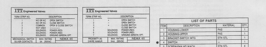
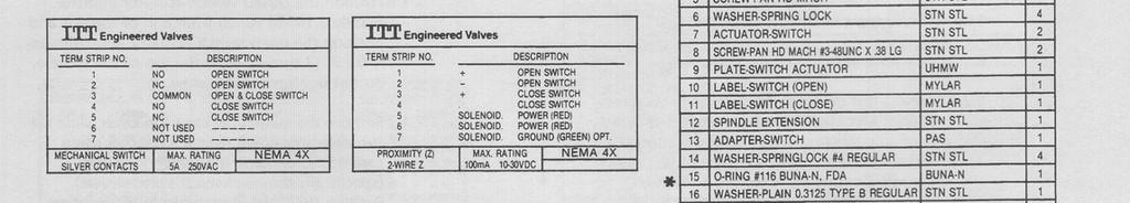
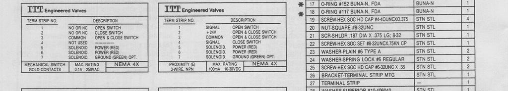
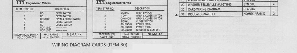
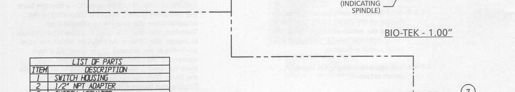
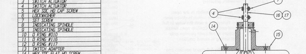
6 below for orientation of u-cup seal in piston groove. There should be axial play between the static lip and retaining shoulder. Maximum allowable torque on this joint is 200 in-lbs for 0.5", 0.75" and 1.0" and 240 in-lbs for 1.5" and 2.0" Reassemble the remainder of the assembly by following the instructions in section ACCESSORIES 4.1 Operation of Adjustable Opening Stop (AOS) Replace indicating spindle/cover o-ring. Lubricate o-rings prior to installation per Section Withdraw valve diaphragm, compressor and spindle assembly from the bonnet Replace valve spindle/piston o-ring and valve spindle/bushing o-ring. Lubricate o-rings prior to installation per Section Reassemble by reversing the instructions in section through Confirm the compressor long fingers are not dragging on bonnet and the stem moves freely. Note: When assembling indicating spindle to valve spindle use Loctite 7649 Primer N followed by Blue Loctite #242. Do not overtighten indicating spindle. Maximum allowable torque on this joint for all assembly sizes is 32 in-lbs (3.6 N-m). Then follow the steps outlined in section through Positioning air inlet and cylinder o-ring replacement (0.50 through 2.00, DN 15-50) Remove actuator from valve body and dismantle actuator following the instructions noted in sections through Remove bushing by turning it counterclockwise to unthread it Lift cylinder from bonnet Replace bushing o-rings. On 1.50 (DN 40) and 2.00 (DN 50), replace cylinder/flanged nut o-ring. Lubricate o-rings prior to installation per Section Orient air inlet on cylinder to the desired position and locate it on bonnet. Make sure that the cylinder is flush with the bonnet Turn the bushing on bonnet clockwise until snug. Note: The.5" size requires a washer under the bushing head. Do not overtighten bushing Remove switch package if present Using air pressure and bleed type regulator, open valve to desired position Rotate AOS spindle counterclockwise until resistance is felt Opening stop is now set. 4.2 Travel (closing) stop and manual over-ride are not available. 5.0 SWITCH PACK 2.0 The switch package is not autoclavable; maximum temperature is 150 F, 65.5 C. Switches and Positioners cannot be used together. Retrofit - The switch package as received from the factory is pre-set, only minimal adjustment is required to adapt to the actuator. 5.1 Field mounting (Bio-Tek through 2.00, DN 8-50) Remove the four (4) stainless steel screws on the actuator top cover. Place the valve in the open position Remove the plastic plug from the indicating spindle Thread the switch indicating spindle into the valve indicating spindle. Use Blue Loctite # Mount the adapter, insure that both o-rings are on the adapter and lubricated with Dow 111. The correct torque is 5.0 in-lbs (.56 N-m) Slide the switch sub assembly down over the adapter, position the conduit entrances in the location most desirable, (45 increments), press down and tighten the set screw located on the side of the lower housing to lock the unit in place. The set screw torque should not exceed 5.0 in-lbs (.56 N-m) Holding the lower housing stationary, unscrew the top switch package cover and wire to the terminal strip (Reference factory wiring decal). Verify the switches operate correctly by cycling the valve, see 5.2 for switch adjusting procedure. Screw the switch
7 package cover on; insure the o-ring remains in the groove. 5.2 Setting switches (Switches are identified with decal) Remove top switch package cover Place valve in full open position Connect test device to terminal strip on connections identified for SW (open) switch. The switch type, inductive proximity versus dry contact mechanical, determines the type of test device required. Contact switches use a traditional voltmeter with resistance capability to verify continuity; inductive proximity switches cannot use this method. Proximity switches require an inductive proximity tester, such as Pepperl+Fuch s model #1-1305, which supplies the proper load and supply voltage to the switch. Inductive proximity switches must be energized with the correct load and supply voltage to sense the target. Do not short the inductive proximity switch by directly connecting a power supply, irreparable and immediate damage can occur to the switch Loosen the two (2) screws on the open switch slightly Use the adjusting screw accessible from the top to move the switch up or down the bracket to the optimum position. (Two turns past the trigger location is recommended.) Tighten the two (2) screws on the switch Place the valve in the full closed position Repeat the above steps for the SW (closed) switch Replace the top switch package cover. 6.0 SWITCH PACK 2.5 The switch package is not autoclavable; maximum temperature is 150 F, 65.5 C. Switches and Positioners cannot be used together. Retrofit - The switch package as received from the factory is pre-set, only minimal adjustment is required to adapt to the actuator. The Switch Pack 2.5 only functions with Bio-Tek through 1" size. 6.1 Field mounting (Bio-Tek through 1.00, DN 8-25) Remove the four (4) stainless steel screws on the actuator top cover. Place the valve in the open position Remove the plastic plug from the indicating spindle Mount the adapter, insure that both o-rings are on the adapter and lubricated with Dow 111. The correct torque is 5.0 in-lbs (.56 N-m) Place the washer on the adapter. Thread the switch indicating spindle (item 12) into the actuator spindle. Use Blue Loctite # Slide the switch sub assembly down over the adapter, position the conduit entrances in the location most desirable, (45 increments), press down and tighten the set screw located on the side of the lower housing to lock the unit in place. The set screw torque should not exceed 5.0 in-lbs (.56 N-m) Attach target assembly (item 9) to switch indicating spindle (item 12) using shoulder screw with Belleville washers in place. Use Blue Loctite #242. Run field wires and conduit to terminal strip. (Reference factory wiring tag.) Verify the switches operate correctly by cycling the valve, see 6.2 for switch adjusting procedure. Screw the switch package cover on; insure the o-ring remains in the groove. 6.2 Setting switches (Switches are identified with decal) Remove top switch package cover Place valve in full open position Connect test device to terminal strip on connections identified for open switch. The switch type, inductive proximity versus dry contact mechanical, determines the type of test device required. Contact switches use a traditional volt meter with resistance capability to verify continuity; inductive proximity switches cannot use this method. Proximity switches require an inductive proximity tester, such as Pepperl+Fuch s model #1-1350, which supplies the proper load and supply voltage to the switch. Inductive proximity switches must be energized with the correct load and supply voltage to sense the target. Do not short the inductive proximity switch by directly connecting a power supply, irreparable and immediate damage can occur to the switch Use the switch actuator (item 7) accessible from the top to set the optimum position. (Two turns past the trigger location is recommended.) Place the valve in the full closed position Repeat the above steps for the SW (Closed) switch Replace the top switch package cover. 7
8 7.0 SWITCH PACK 3.0 & VSP The switch package is not autoclavable; maximum temperature is 140 F, 60.0 C. Switches and Positioners cannot be used together. Retrofit - The switch package as received from the factory on valve assemblies is pre-set, only minimal adjustment is required to adapt to the actuator. 7.1 Field mounting (Bio-Tek through 2.00, DN 8-50) Remove the four (4) stainless steel screws on the actuator top cover. Place the valve in the open position Remove the plastic plug from the indicating spindle Insure all o-rings are on the adapter and lubricated with Dow 111. Slip the switch indicating spindle, #10-24 UNC threads first, through the adapter until the threads are exposed. Apply Blue Loctite #242 to the threads, thread the switch spindle into the actuator spindle until it shoulders Attach the adapter to the upper cover. The correct torque is 5.0 in-lbs (.56 N-m) Thread the appropriate switch actuator(s) on the spindle Position the closed switch actuator approximately 0.14 (4 turns) from end of threads and position the open switch actuator approximately 0.25 (7 turns) below the top of the spindle, do not tighten the set screw Connect test device to terminal strip for open switch. The switch type, inductive proximity versus dry contact mechanical, determines the type of test device required. Contact switches use a traditional volt meter with resistance capability to verify continuity; inductive proximity switches cannot use this method. Proximity switches require an inductive proximity tester, such as Pepperl+Fuch s model #1-1350, which supplies the proper load and supply voltage to the switch. Inductive proximity switches must be energized with the correct load and supply voltage to sense the target. Do not short the inductive proximity switch by directly connecting a power supply, irreparable and immediate damage can occur to the switch Verify the circuit board is firmly seated (SP3.0 style) For mechanical switches only, press on the top of the circuit board to move it toward the switch actuator (SP3.0 style). Thread the switch actuator two (2) turns past the initial switch indication Lock in place with the set screw on switch actuator Place the valve in the full closed position and connect the appropriate test device to the terminal strip for valve CLOSED switch. Repeat section for the valve CLOSED switch. Note on SP 3.0 units, the closed switch actuator must never hit the adapter in the closed position with body attached Remove the switch package top cover; slide the sub assembly down over the adapter using care not to damage the switch internals (specifically the mechanical switch levers). Position the conduit entrance in the location most desirable, press down and tighten the set screw located on the side of the lower housing to lock the unit in place. Note that the plastic adapter has two molded counterbores. Locating the set screw in one of these holes provides maximum resistance to conduit rotation. The set screw torque should not exceed 5.0 in-lbs. (.56 N-m) Run field wires and conduit to the terminal strip. Verify the switches operate correctly by cycling the valve. See 7.2 for switch adjusting procedure. Screw the switch package top cover on. 7.2 Setting switches Verify the switch package locking set screw is tight Remove top switch package cover Place valve in full open position. 8
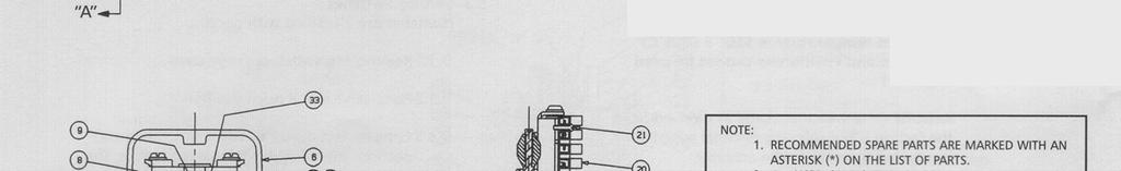
9 ADVANTAGE PISTON ACTUATOR FIGURE 1 LIST OF PARTS ITEM DESCRIPTION MATERIAL QTY 1 STANDARD ITT BODY STN. STL. 1 2 STANDARD ITT ELASTOMER EPDM, BUNA-N 1 DIAPHRAGMS 3 BONNET STN. STL. 1 4 COMPRESSOR ZINC 1 5 WASHER, PLAIN STN. STL. 4 6 NUT, HEX STN. STL. 4 7 SCREW, HEX HD CAP STN. STL. 4 8 SPINDLE, VALVE STN. STL. 1 9 PLUG PLASTIC 1 10 SCREW, MACHINE RD HEAD STN. STL PIN, COMPRESSOR STN. STL O-RING BUNA-N 2 13 BUSHING BRASS 1 14 O-RING BUNA-N 1 15 SEAL, PISTON BUNA-N 1 16 PISTON ZINC 1 17 SPRING, OUTER STEEL 1 18 SPRING, INNER STEEL 1 19 O-RING BUNA-N 2 20 CYLINDER GLASS REINFORCED POLYESTER (PBT) 1 21 COVER, CYLINDER GLASS REINFORCED POLYESTER (PBT) 1 22 SPINDLE, INDICATING STN. STL WASHER STN. STL RING, RETAINING STN. STL COMPRESSOR ZINC 1 26 BACKING CUSHION EPDM 1 27 STANDARD ITT PTFE, GRADE TM OR PLASTIC DIAPHRAGMS R TUBE NUT BRASS 1 PLASTIC DIAPHRAGM DETAIL DIMENSIONAL DATA Valve Size A B C D Inch DN Inch cm Inch cm Inch cm Inch cm * Buttweld is 3.50 / 8.89 cm, Tri-Clamp is 2.53 / 6.43 cm 9


10 ADVANTAGE PISTON ACTUATOR FIGURE 2 ADJUSTABLE OPENING STOP (AOS) COVER, CYLINDER O-RING AOS SPINDLE VALVE SPINDLE SPRING PLUNGER (Actuator shown in valve s closed position.) FIGURE 3 VALVE DIAPHRAGM IDENTIFICATION ELASTOMER THESE DIAPHRAGMS ARE ONE-PIECE, MADE OF RUBBER, WITH MOLDED IN STUD. (SEE TABS) R2, TM (PTFE) THESE DIAPHRAGMS ARE TWO-PIECE, WHITE PLASTIC WITH A BLACK EPDM BACKING CUSHION. 10


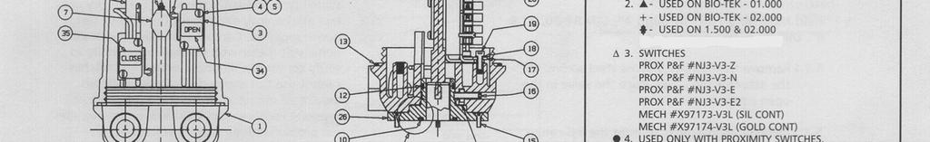
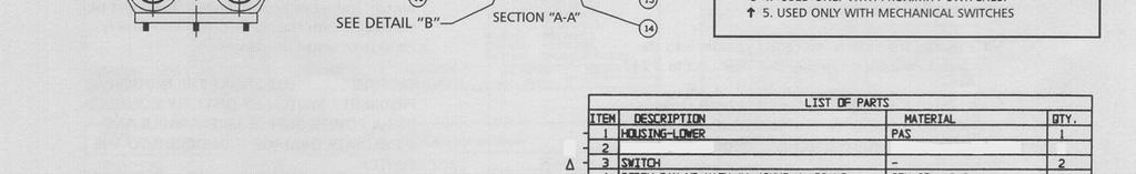

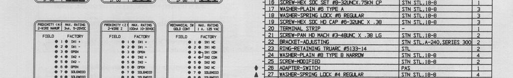
11 SWITCH PACK 2, SP2.0 FIGURE 4 11


12 SWITCH PACK 2.5, SP2.5 FIGURE 4A 12


13 SWITCH PACK 3, SP3.0 FIGURE 4B 13
14 TABLE 1 FASTENER TORQUES BODY TO BONNET Valve Size PTFE Elastomer Diaphragm Diaphragm Inch DN in-lbs (N-m) in-lbs (N-m) 0.50" ( ) ( ) 0.75" ( ) ( ) 1.00" ( ) ( ) 1.25" & 1.50" 32 & (23-25) ( ) 2.00" (25-31) (11-20) Notes: 1. Make multiple criss-cross passes to build up torque to final table values. Make additional criss-cross passes using table values to evenly tighten each bolt to within 5% of stated torque. 2. Values given are for lubricated fasteners. 3. Minimum values given will provide longer diaphragm cycle life for valves in non-autoclave and low thermal cycle conditions. 4. Maximum values given will be required for autoclave conditions and for high thermal cycle conditions. 5. Torques should be applied at near ambient conditions ( < 100 F). TABLE 2 NOMINAL ACTUATOR TRAVEL Valve Inch Size DN Valve Inch Stroke mm ADVANTAGE PISTON ACTUATOR WEIGHTS Weights are less body and diaphragm Valve Size 60 PSI 90 PSI Spring Package Spring Package Inch DN lbs kg lbs kg 0.50" " TABLE 3 APPROXIMATE MAXIMUM CHAMBER VOLUME Valve Size Piston Chamber Inch DN in 3 cm " " " " "
15 NOTES 15

16 Indianapolis Chicago San Juan ITT Pure-Flo OFFICE LOCATIONS For more information, please contact: Pure-Flo Headquarters 33 Centerville Road, P.O. Box 6164 Lancaster, PA USA Or call: (800) (717) Fax (717) Website: Pure-Flo 110-B West Cochran Street Simi Valley, CA Phone Phone (805) Fax (805) Pure-Flo Richards Street Kirkham, Lancashire PR4 2HU, England Phone Fax ITT Corporation Industrial Process 16
Installation and Operation Manual
 Industrial Process Installation and Operation Manual Advantage Actuator 2.0 Table of Contents Table of Contents Introduction and Safety...2 Safety message levels...2 User health and safety...2 Transportation
Installation and Operation Manual
 Indianapolis Chicago San Juan www.hollandapt.com 800-800-8464 Industrial Process Installation and Operation Manual Value Switch Package (VSP) Table of Contents Table of Contents Introduction and Safety...2
Installation and Operation Manual
 Indianapolis Chicago San Juan www.hollandapt.com 800-800-8464 Industrial Process Installation and Operation Manual Switch Package 2 (SP2) Table of Contents Table of Contents Introduction and Safety...2
Installation and Operation Manual
 Industrial Process Installation and Operation Manual Switch Package 3 (SP3) Indianapolis Chicago San Juan www.hollandapt.com 800-800-8464 Table of Contents Table of Contents Introduction and Safety...2
Installation and Operation Manual. Value Switch Package (VSP and VSP+)
") Installation and Operation Manual Value Switch Package (VSP and VSP+) Table of Contents Table of Contents Introduction and Safety... 2 Safety message levels... 2 User health and safety... 2 Transportation
Installation and Operation Manual Value Switch Package (VSP and VSP+) Table of Contents Table of Contents Introduction and Safety... 2 Safety message levels... 2 User health and safety... 2 Transportation
Installation, Operation, and Maintenance Manual
 Industrial Process Installation, Operation, and Maintenance Manual Cam-Tite Ball Valve Table of Contents Table of Contents Introduction and Safety...2 Safety message levels...2 User health and safety...2
Pure-Flo. Topworks.
 Pure-Flo Topworks Table of Contents Introduction..............3 Manual Topworks 963 PAS Bonnet........4-5 970 Stainless Steel Bonnet..6 913 Stainless Steel Bonnet..7 903 Cast Iron Bonnet......8 Bio-Tek
Installation, Operation, and Maintenance Manual
 Industrial Process Installation, Operation, and Maintenance Manual Series PBV Plastic Lined Ball Valve Table of Contents Table of Contents Introduction and Safety...2 Safety message levels...2 User health
Installation, Operation, and Maintenance Manual
 Industrial Process Installation, Operation, and Maintenance Manual Series PBFV Plastic Lined Butterfly Valve - Lug and Wafer Style Table of Contents Table of Contents Introduction and Safety...2 Safety
Manually Operated Diaphragm Valves
 Manually Operated Diaphragm Valves Page 1 of 7 OPERATING PRESSURE AND TEMPERATURE Non-shock pressure at temperature range Non-shock pressure at max. temperature ½ -2 (DN15-DN50) 230 psig from 0ºF to 100ºF
Pure-Flo. Automation & Control.
 Pure-Flo Automation & Control Table of Contents Introduction..............3 Value Switch Package......4-5 Switch Package SP2.......6-7 Switch Package SP3.......8-9 Pneumatic Positioner.......10 Manual
Pure-Flo. Bio-Pure.
 Pure-Flo Bio-Pure www.ittpureflo.com The Bio-Pure is the compact solution for the most demanding Biopharm applications. vailable in fractional sizes and a wide selection of body materials and end connections
DIA-FLO & PURE-FLO Diaphragm Valves Instruction Manual With Dia-Flo Actuator
 DFAMM-01 DIA-FLO & PURE-FLO Diaphragm Valves Instruction Manual With Dia-Flo Actuator This manual provides installation and maintenance instructions for DIA-FLO ACTUATOR operated DIA-FLO/PURE-FLO diaphragm
Model DFR 070/156/220 Rotary Actuator
 Figure 1 DFR 156 TABLE OF CONTENTS General 2 Actuator Assembly 18 Scope 2 Bushing / Yoke Assembly 18 Principles of Operation 2 Spring Barrel Assembly 18 Safety Caution 2 Diaphragm Plate Assembly 20 Specifications
Pure-Flo Advantage 2.1 Actuator
 Pure-Flo Advantage 2.1 Actuator Advantage 2.1 Actuator / Design The Next Evolution in Actuation Performance The Advantage 2.1 actuator is the latest evolution in performance of the time-tested Advantage
Mounting and Operating Instructions EB 8039 EN. Type 3351 Pneumatic On/off Valve. Type 3351 Pneumatic On/off Valve. Type 3351 Pneumatic On/off Valve
 Type 3351 Pneumatic On/off Valve Type 3351 Pneumatic On/off Valve Type 3351 Pneumatic On/off Valve Version with handwheel Mounting and Operating Instructions EB 8039 EN Edition May 2016 Definition of signal
Mounting and Operating Instructions EB EN. Type 3372 Electropneumatic Actuator. Actuator area: 120 and 350 cm² With Type 3725 Positioner
 Type 3372 Electropneumatic Actuator Actuator area: 120 and 350 cm² With Type 3725 Positioner Translation of original instructions Type 3372 with 120 cm² actuator area Type 3372 with 350 cm² actuator area
Mounting and Operating Instructions EB EN. Type 3271 and Type 3277 Pneumatic Actuators. Actuator areas: 175v2, 350v2, and 750v2 cm²
 Type 3271 and Type 3277 Pneumatic Actuators Actuator areas: 175v2, 350v2, and 750v2 cm² Translation of original instructions Type 3271 (left) and Type 3277 (right) Pneumatic Actuators Mounting and Operating
DA Series Diaphragm Valve
 DA Series Diaphragm Valve Service Instructions Pneumatically Actuated Valve Toggle Valve Valve Valve Valves are shown with tube butt weld ends. These instructions also apply to DA series valves with any
Mounting and Operating Instructions
 Mounting and Operating Instructions EB 8310-6 EN Translation of original instructions Type 3271 Type 3277 Type 3271 and Type 3277 Pneumatic Actuators Actuator area: 240, 350, and 700 cm² Edition March
Mounting and Operating Instructions EB EN. Type 3271 Pneumatic Actuator. Actuator area: 1000 cm². Translation of original instructions
 Type 3271 Pneumatic Actuator Actuator area: 1000 cm² Translation of original instructions Type 3271 Pneumatic Actuator Mounting and Operating Instructions Edition April 2018 Note on these mounting and
Fisher 657 Diaphragm Actuator Sizes and 87
 Instruction Manual 657 Actuator (30-70 and 87) Fisher 657 Diaphragm Actuator Sizes 30 70 and 87 Contents Introduction... 1 Scope of Manual... 1 Description... 2 Specifications... 2 Installation... 3 Mounting
Mounting and Operating Instructions EB 8048 EN. Type and Type Pneumatic Control Valves Type 3249 Aseptic Angle Valve
 Type 3249-1 and Type 3249-7 Pneumatic Control Valves Type 3249 Aseptic Angle Valve Ball body version Special version with packing Type 3249-7 Control Valve with Type 3277 Actuator and integrated positioner
INSTRUCTION AND MAINTENANCE MANUAL FR95 PRESSURE REGULATOR
 Enidine / Conoflow 105 Commerce Way Westminster, SC 29693 Tel: (864) 647-9521 Fax: (864) 647-7993 WARNING Conoflow s products are designed and manufactured using materials and workmanship required to meet
Model 3051 Sensor Module Replacement
 Model 3051 Sensor Module Replacement 00809-0400-4001 English Rev. BA SAFETY MESSAGES Procedures and instructions in this manual may require special precautions to ensure the safety of the personnel performing
Pressure relief valve
 Pressure relief valve Operating manual Series DHV 712 Version BA-2015.10.20 EN Print-No. 300 510 TR MA DE Rev001 ASV Stübbe GmbH & Co. KG Hollwieser Straße 5 32602 Vlotho Germany Phone: +49 (0) 5733-799-0
DR Series Radial Diaphragm Valves
 DR Series Radial Valves Service Instructions Valves with Plastic Actuators (1/2 through 1 inch) Valves with Aluminum Actuators (1/2 through 2 inch) Manual model Pneumatic model Manual model Pneumatic model
33 CENTERVILLE ROAD LANCASTER, PA
 33 CENTERVILLE ROAD LANCASTER, PA 17603-2064 TEL: (717) 509-2200 FAX: (717) 509-2336 INSTALLATION, OPERATION AND MAINTENANCE INSTRUCTIONS MODEL T2005 & T2006 SKOTCH TRIFECTA OIL VALVE SYSTEMS WARNING Valves
CONTENTS. VIKING PUMP, INC. A Unit of IDEX Corporation Cedar Falls, IA USA SECTION TSM 710.1
 TECHNICAL SERVICE MANUAL industrial heavy duty motor speed pumps SERIES 4076 AND 4176 SIZES hle, ate and ale SECTION TSM 710.1 PAGE 1 of 8 ISSUE B CONTENTS Introduction....................... 1 Safety
Mounting and Operating Instructions EB 8053 EN. Series 250 Type and Type Pneumatic Control Valves
 Series 250 Type 3252 1 and Type 3252 7 Pneumatic Control Valves Type 3252 High-pressure valve with Type 3277 Pneumatic Actuator and Type 3767 Electropneumatic Positioner Mounting and Operating Instructions
Maintenance Information
 04581245 Edition 2 May 2014 Air Grinder, Die Grinder and Sander Series G2 (Angle) Maintenance Information Save These Instructions Product Safety Information WARNING Failure to observe the following warnings,
INSTRUCTION AND MAINTENANCE MANUAL GFH45 PRESSURE REGULATOR
 Enidine / Conoflow 105 Commerce Way Westminster, SC 29693 Tel: (864) 647-9521 Fax: (864) 647-7993 WARNING Conoflow s products are designed and manufactured using materials and workmanship required to meet
MK-6600 Series, MK-6800 Series, and MK-6911
 MK-6600 Series, MK-6800 Series, and MK-6911 Pneumatic Valve Actuators General Instructions Application These valve actuators, with a 50 sq. in. (323 cm 2 ) effective diaphragm area, are used for proportional
Baumann Sanitary Diaphragm Angle and Inline Control Valve
 Instruction Manual 84000 Valve Baumann 84000 Sanitary Diaphragm Angle and Inline Control Valve Contents Introduction... 1 Scope of Manual... 1 Safety Precautions... 2 Maintenance... 2 Flow Direction...
DELTA O-RING CARTRIDGE SEAL ASSEMBLY AND INSTALLATION INSTRUCTIONS INTRODUCTION:
 DELTA O-RING CARTRIDGE SEAL ASSEMBLY AND INSTALLATION INSTRUCTIONS INTRODUCTION: These instructions are provided to familiarize the user with the seal and its use. The instructions must be read carefully
DP Series Diaphragm Valve Installation and Maintenance Instructions
 DP Series Diaphragm Valve Installation and Maintenance Instructions Contents Installation Actuation Actuator Orientation Welding Testing Maintenance Kit Contents Tool Requirements Exploded View Replacing
Pressure Relief Valve Maintenance Manual
 Technical Manual 1098T Pressure Relief Valve Maintenance Manual Farris Engineering Division of Curtiss-Wright Flow Control Corporation TABLE OF CONTENTS - Manual Revision 0 Introduction & Safety Tips...
Type 3571 Pneumatic Actuator. Actuator areas: 27 in² 54 in² 116 in². Original instructions. Mounting and Operating Instructions EB 8820 EN
 Type 3571 Pneumatic Actuator Actuator areas: 27 in² 54 in² 116 in² Original instructions Mounting and Operating Instructions Edition April 2016 Note on these mounting and operating instructions These mounting
CONTROL VALVES. Installation, Maintenance & Operating Instructions. Read these instructions carefully before installation or servicing.
 KOSO HAMMEL DAHL CONTROL VALVES KOSO HAMMEL DAHL 253 Pleasant Street West Bridgewater, MA 02379 tel: 774.517.5300 fax: 774.517.5230 www.hammeldahl.com Installation, Maintenance & Operating Instructions
Operating & Maintenance Manual For Steam Conditioning Valve
 For Steam Conditioning Valve 1 Table of Contents 1.0 Introduction 3 2.0 Product description 3 3.0 Safety Instruction 4 4.0 Installation and Commissioning 5 5.0 Valve Disassembly 6 6.0 Maintenance 6 7.0
HIGH PRESSURE CONTROL VALVE PISTON BALANCED
 PISTON BALANCED All Rights Reserved. All contents of this publication including illustrations are believed to be reliable. And while efforts have been made to ensure their accuracy, they are not to be
Installation, Operation and Maintenance Guide II NIBCO High Performance Butterfly Valves Series 6822 and 7822
 Installation, Operation and Maintenance Guide II NIBCO High Performance Butterfly Valves Series 6822 and 7822 Statements: NIBCO High Performance Butterfly Valves, Series 6822 and 7822, have been designed
Model DFR 026 Rotary Actuator
 Figure DFR 026 and 57 Control Valve TABLE OF CONTENTS General 2 Actuator Assembly 4 Scope 2 Bushing Installation 4 Principles of Operation 2 Mounting Yoke / Hub Assembly 4 Safety Caution 2 Spring / Adjuster
Globe Control Valve Series 1a
 Maintenance Globe Control Valve Series 1a are subject to alteration without notice. The text and illustrations do not necessarily display the scope of supply or any ordering of spare parts. Drawings and
DL/DS Series Diaphragm Valve
 DL/DS Series Diaphragm Valve Service Instructions DL Series (Lever Handle) Valve DS Series (Round Handle) Valve Valves are shown with tube butt weld ends. These instructions also apply to DL or DS series
Sub Section Title Page No.
 Sub Section Title Page No. 1 Introduction 3 2 Routine Maintenance 3 3 Disassembly 4 3.1 Disassembly of Double Crank Design 4 3.2 Disassembly of Scotch Yoke Design 5 3.3 Disassembly of Actuator Cylinder
Standard Valves Series Globe Valves Series Angle Valves Series Way-Valves
 Installation, Operation, Maintenance Instructions Standard Valves Series 035 000 Globe Valves Series 031 000 Angle Valves Series 033 000 3-Way-Valves 1 GENERAL INFORMATION These instructions are designed
USER INSTRUCTIONS. Kämmer SmallFlow / / SP Low and Micro Flow Valves. Installation Operation Maintenance
 User Instructions SmallFlow - KMENIM5000-02 02/15 USER INSTRUCTIONS Kämmer SmallFlow - 385000 / 385300 / 385000 SP Low and Micro Flow Valves FCD KMENIM5000-02 02/15 Installation Operation Maintenance Experience
ONYX VALVE CO MODEL DAO-PFC Installation & Maintenance
 ONYX VALVE CO MODEL DAO-PFC Installation & Maintenance OPERATION: (4-2010) The Onyx DAO-PFC pinch valve is an open frame valve without housing enclosure and fails closed on loss of air. The actuator drives
CVS Type 667 Diaphragm Actuator Sizes 30-70
 Instruction Manual CVS Type 667 Diaphragm Actuator Sizes 30-70 All CVS Controls actuators are to be installed and maintained in accordance with instructions supplied by CVS Controls. This manual includes
ONYX VALVE CO MODEL DAO-PFO Installation & Maintenance
 ONYX VALVE CO MODEL DAO-PFO Installation & Maintenance OPERATION: (4-2010) The Onyx DAO-PFO pinch valve is an open frame valve without housing enclosure and fails open on loss of air. The actuator drives
KOSO HAMMEL DAHL CONTROL VALVES
 KOSO HAMMEL DAHL CONTROL VALVES KOSO HAMMEL DAHL 253 Pleasant Street West Bridgewater, MA 02379 tel: 774.517.5300 fax: 774.517.5230 www.hammeldahl.com Installation, Maintenance & Operating Instructions
KLINGER Piston Valves KVN DN PN 16 I/III with valve ring KX-GT Modul
 Page 1 Assembly Instructions and Handling Regulations for KLINGER Piston Valves KVN DN 65 150 PN 16 I/III with valve ring KX-GT Modul DN 125-150 1 Body 2 Bonnet 3 Hand wheel 4 Piston 5 Lantern bush 8 Threaded
CV Control Valves Installation and Operation Manual
 CV1500 - Control Valves Installation and Operation Manual 652-EN Overview Warning: This bulletin should be used by experienced personnel as a guide to the installation of the Armstrong CV1500 Control Valve.
Maintenance Information
 80234313 Edition 1 June 2006 Air Grinder, Die Grinder, Sander and Belt Sander Series G1 (Angle) Maintenance Information Save These Instructions WARNING Always wear eye protection when operating or performing
Model DF233 Control Valve
 Figure 1 DF233 Control Valve TABLE OF CONTENTS Introduction 2 Body and Packing Reassembly 7 Specifications 3 Fail Closed Actuator Reassembly 8 Valve Sizes 3 Fail Open Actuator Reassembly 9 Unpacking 4
MODEL 5540 CONTENTS. Installation, Operation and Maintenance Instructions 1.0 GENERAL
 Installation, Operation and Maintenance Instructions MODEL 5540 Sep 20 CONTENTS.0 GENERAL. Model Number---------------------------------------------------------------------------------------------------------------
Maintenance Information
 80234313 Edition 2 May 2014 Air Grinder, Die Grinder, Sander and Belt Sander Series G1 (Angle) Maintenance Information Save These Instructions Product Safety Information WARNING Failure to observe the
Fisher 3024C Diaphragm Actuator
 Instruction Manual 3024C Actuator Fisher 3024C Diaphragm Actuator Contents Introduction... 1 Scope of Manual... 1 Description... 2 Specifications... 3 Installation... 5 Mounting the Actuator on the Valve...
LOW PRESSURE BALANCED VALVE DIAPHRAGM BALANCED
 DIAPHRAGM BALANCED All Rights Reserved. All contents of this publication including illustrations are believed to be reliable. And while efforts have been made to ensure their accuracy, they are not to
Fisher 1061 Pneumatic Piston Rotary Actuator with Style H & J Mounting Adaptations
 Instruction Manual 1061 H & J Actuator Fisher 1061 Pneumatic Piston Rotary Actuator with Style H & J Mounting Adaptations Contents Introduction... 1 Scope of Manual... 1 Description... 2 Specifications...
Fisher 1051 and 1052 Style H and J Sizes 40, 60 and 70 Rotary Actuators
 Instruction Manual 1051 and 1052 H & J Actuators Fisher 1051 and 1052 Style H and J Sizes 40, 60 and 70 Rotary Actuators Contents Introduction... 1 Scope of Manual... 1 Description... 2 Specifications...
Model DF269 Control Valve
 Figure 1 DF269 Control Valve TABLE OF CONTENTS Introduction 2 Fail Open Actuator Disassembly 6 General 2 Body and Packing Reassembly 7 Scope 2 Fail Closed Actuator Resassembly 8 Specifications 3 Fail Open
ONYX VALVE CO MODEL DAO-ADA Installation & Maintenance
 ONYX VALVE CO MODEL DAO-ADA Installation & Maintenance OPERATION: (4-2010) The Onyx DAO-ADA pinch valve is an open frame valve without housing enclosure and fails last position on loss of air. This actuator
J Flow Controls Model Numbering
 4665 Interstate Dr Cincinnati, OH 45246 Phone 513-731-2900 Fax 513-731-6939 3500 Series Valve Instruction and Maintenance Manual Caution: Prior to performing any repairs or maintenance on the valve assembly,
Fisher 2052 Diaphragm Rotary Actuator
 Instruction Manual 2052 Actuator Fisher 2052 Diaphragm Rotary Actuator Contents Introduction... 1 Scope of Manual... 1 Description... 1 Specifications... 4 Installation... 4 Actuator Mounting and Changing
Air Operated Double Diaphragm Pump. M-Pump ½ Metallic Non Metallic Pump INSTALLATION, OPERATION & MAINTENANCE MANUAL
 Air Operated Double Diaphragm Pump M-Pump ½ Metallic Non Metallic Pump INSTALLATION, OPERATION & MAINTENANCE MANUAL 0.5 I.O.M rev 05. 12/2015 INDEX Title Section Introduction.1 Safety.2 Warranty, General
Nor East. Instructions Safety Messages. Inspection. Parts. DeZURIK Service. Type 05 Pneumatic Actuator Used With Globe Valves
 Instructions Safety Messages These instructions are intended for personnel who are responsible for installation, operation and maintenance of your DeZURIK Actuator. All safety messages in the instructions
Keystone Series GR resilient seated butterfly valves GRW/GRL Installation and operation manual
 Before installation these instructions must be fully read and understood Important Before valves are installed or used the following actions are recommended. 1. Valves/parts have to be inspected and thoroughly
DeZURIK DR 125 ROTARY DIAPHRAGM ACTUATOR
 DR 125 ROTARY DIAPHRAGM ACTUATOR Instruction D10507 January 2017 Instructions These instructions provide information about. They are for use by personnel who are responsible for installation, operation
In combination with an actuator, e.g. a SAMSON Type 3271 or Type 3277 Pneumatic Actuator
 Type 3510 Micro-flow Valve In combination with an actuator, e.g. a SAMSON Type 3271 or Type 3277 Pneumatic Actuator DIN version Translation of original instructions Type 3510-1 (left) and Type 3510-7 (right)
TECHNICAL SERVICE MANUAL
 Electronic copies of the most current TSM issue can be found on the Viking Pump website at www.vikingpump.com TECHNICAL SERVICE MANUAL industrial heavy duty motor speed pumps SERIES 4076 AND 4176 SIZES
Model DFRP Rotary Actuator
 Figure 1 6 Inch 590 with DFRP-112 TABLE OF CONTENTS General 2 Actuator Assembly 17 Scope 2 Bushing / Yoke Assembly 17 Principles of Operation 2 Cylinder Assembly 18 Safety Caution 2 Piston Assembly 19
Baumann Sanitary Diaphragm Angle & In-Line Control Valve Instructions
 Instruction Manual D103370X012 84000 Control Valve Baumann 84000 Sanitary Diaphragm Angle & In-Line Control Valve Instructions CONTENTS Introduction...1 Scope...1 Safety P recautions...1 Maintenance...2
Calibration and Switching Module. User s Manual. A Swagelok Pre-Engineered. Subsystem. Pre-engineered subsystems available in weeks, not months.
 Calibration and Switching Module User s Manual A Swagelok Pre-Engineered Subsystem Pre-engineered subsystems available in weeks, not months. Field-tested design ensures optimum system performance. Contents
Tri-Clover Manual and Air Actuated Fractional Valves
 FVSM-99 Tri-Clover Manual and Air Actuated Fractional Valves Series 650 655 660 CONTENTS Thank you for purchasing an Alfa Laval Product! This manual contains disassembly and assembly instructions, maintenance
Full View Flow Indicator
 Full View Flow Indicator Threaded and Flanged Process Connection Installation / Operation / Maintenance Manual P.O. Box 1116 Twinsburg, OH 44087 Phone: 330/405-3040 Fax: 330/405-3070 E-mail: view@ljstar.com
Fisher RSS Lined Globe Valve
 Instruction Manual D0990 RSS Valve July 07 Fisher RSS Lined Globe Valve Contents Introduction... Scope of Manual... Description... Educational Services... Specifications... Installation... Maintenance...
Flow Line Controls. Installation & Operations Manual SERIES 20/21 Pneumatic Actuators
 Flow Line Controls Installation & Operations Manual SERIES 20/21 Pneumatic Actuators Flow Line Controls, Inc. P.O. Box 677 Schriever, LA 70395 Phone: 985-414-6003 Toll Free 1-800-815-9226 Fax 985-414-6072
Mounting and Operating Instructions EB 8097 EN. Pneumatic Control Valves Type and Type
 Pneumatic Control Valves Type 3347-1 and Type 3347-7 Hollow-mold cast body with welding ends Full-mold cast body with threaded connections Fig. 1 Type 3347-7 Control Valve with Type 3277 Actuator and integral
Dome-Loaded Pressure Reducing BD-Series
 Dome-Loaded Pressure Reducing BD-Series *Parts will differ for high pressure valves. Load Piston - Piston - U-cup U-cup Piston 1. Carefully place the u-cup over the neck of the piston. Load Cylinder -
Standard Bore Flanged Ball Valves Series 7150, 730S & , 4 & 6 (DN 80, 100 & 150) Class 150 & 300
 Class 150 & 300") Standard Bore Flanged Ball Valves Series 7150, 730S & 7300 3, 4 & 6 (DN 80, 100 & 150) Class 150 & 300 Installation, Maintenance and Operating Instructions IMO-299 EN 9/2017 2 IMO-299 EN TABLE OF CONTENTS
Standard Bore Flanged Ball Valves Series 7150, 730S & 7300 3, 4 & 6 (DN 80, 100 & 150) Class 150 & 300 Installation, Maintenance and Operating Instructions IMO-299 EN 9/2017 2 IMO-299 EN TABLE OF CONTENTS
KHR Series Regulators
 KHR Series Regulators Maintenance Instructions Kit Contents retainer Poppet Poppet spring Poppet damper Outer body seal Inner body seal Upper piston seal seal backup ring Main piston seal vent seal Self-vent
Keystone Butterfly valves ParaSeal Installation and maintenance instructions
 Before installation these instructions must be fully read and understood Please read these instructions carefully Hazard potentials: disregarding of instructions improper use of product insufficiently
INSTALLATION/OPERATION/MAINTENANCE INSTRUCTIONS FOR ARCHON MODELS WD2010L, WD2010, WD2010H WASHDOWN STATIONS. ARCHON Industries, Inc.
 ARCHON Industries, Inc. Washdown Stations Models WD2010L, WD2010, WD2010H Installation / Operation / Maintenance Instructions 1 This manual has been prepared as an aid and guide for personnel involved
Operating Manual High Viscosity Dispense Valve Item #
 Operating Manual High Viscosity Dispense Valve Item # 984594 CLOSE OPEN Item # 984594 Label # 8901197 Warnings INJECTION HAZARD Spray from the valve, hose leaks, or ruptured components can inject fluid
Apollo Standard Port, Full Port & One Piece Flanged Ball Valves Installation, Operation, & Maintenance Guide
 I854000.F M16005 Apollo Standard Port, Full Port & One Piece Flanged Ball Valves Introduction This manual presents guidelines for the Installation, Operation and Maintenance of manual and automated Apollo
INSTRUCTION AND MAINTENANCE MANUAL GC31 COMMANDAIRE POSITIONER
 Enidine / Conoflow 15 Commerce Way Westminster, SC 29693 Tel: (864) 647-9521 Fax: (864) 647-7993 WARNING Conoflow products are designed and manufactured using materials and workmanship required to meet
INSTALLATION - MAINTENANCE MANUAL Severe Service Series M4 Ball Valve
 INSTALLATION - MAINTENANCE MANUAL Severe Service Series M4 Ball Valve Date: May 2016/ Page 2 of 12 Table of Contents 1. Safety Information - Definition of Terms..........................2 2. Bill of Materials....................................
Maintenance Information
 16573370 Edition 2 February 2014 Air Grinder 99V Series Maintenance Information Save These Instructions Product Safety Information WARNING Failure to observe the following warnings, and to avoid these
DeZURIK 2 20" BOS BUTTERFLY VALVES
 2 20" BOS BUTTERFLY VALVES Instruction D10459 October 2013 2-20 BOS Butterfly Valves Instructions These instructions provide information about BOS Butterfly Valves. They are for use by personnel who are
Split Body Valves with Bellows Seal Series Globe Valves Series Angle Valves Series Way-Valves
 Installation, Operation, Maintenance Instructions Split Body Valves with Bellows Seal Series 025 300 Globe Valves Series 027 300 Angle Valves Series 028 300 3-Way-Valves 1 GENERAL INFORMATION These instructions
Anderson Greenwood Series 400 Piston Pilot POPRV Installation and Maintenance Instructions
 Before installation these instructions must be fully read and understood As capacity relief of the system is satisfied, system pressure will begin to decrease. When it does, the pilot will actuate and
Bray/ VAAS Slurry Series Knife Gate Valve 760/762/765/766/767/768 Series Operation and Maintenance Manual
 Bray/ VAAS Knife Gate Valve 760/762/765/766/767/768 Series Table of Contents Definition of Terms 1 Safety Instructions 1 Introduction 2 Unpacking 2 Storage 2 Installation 3 Commissioning 3 Cylinder-Operated
Fisher 667NS2 Diaphragm Actuator Size 45, 70, and 80
 Instruction Manual 667NS Actuator Fisher 667NS Diaphragm Actuator Size 5, 70, and 80 Contents Introduction... 1 Scope of Manual... 1 Description... Specifications... 3 Educational Services... 3 Maximum
John Crane Type 5620 and 5620PR Dual O-Ring Cartridge Seal Assembly and Installation Instructions
 I-5620/5620PR-A John Crane Type 5620 and 5620PR Dual O-Ring Cartridge Seal Assembly and Installation Instructions Foreword These instructions are provided to familiarize the user with the seal and its
Type 657 Diaphragm Actuator Sizes and 87
 Instruction Manual Form 1900 January 2000 Type 657-70 & 87 Type 657 Diaphragm Actuator Sizes 30-70 and 87 Contents Introduction............................... 1 Scope of Manual.............................
105 Commerce Way Westminster, SC Tel: (864) Fax: (864)
 Fax: (864)") ITT Conoflow 105 Commerce Way Westminster, SC 29693 Tel: (864) 647-9521 Fax: (864) 647-9574 WARNING Conoflow s products are designed and manufactured using materials and workmanship required to meet all
ITT Conoflow 105 Commerce Way Westminster, SC 29693 Tel: (864) 647-9521 Fax: (864) 647-9574 WARNING Conoflow s products are designed and manufactured using materials and workmanship required to meet all
Type 3271 and Type 3277 Pneumatic Actuators. Actuator areas: 175 and 750 cm². Type 3271 Type Mounting and Operating Instructions EB EN
 Type 3271 and Type 3277 Pneumatic Actuators Actuator areas: 175 and 750 cm² Type 3271 Type 3277 Type 3271 and Type 3277 Pneumatic Actuators Mounting and Operating Instructions EB 8310-5 EN Edition October