KC102 Series Engine Control System
|
|
|
- Ross Bradford
- 6 years ago
- Views:
Transcription
1 KC102 Series Engine Control System Chapter 0 Operation of KC102 / KC102E Engine Control System. Description of H102 series control head keypad Error code on control head Chapter 1 Description of H102/ H102A Control Head Chapter 2 Description of A102 Actuator unit Error code for actuator Chapter 3 Single line cabling & Wire Termination Chapter 4 Power Up & Initial Checks. Actuator & Control heads error code Chapter 5 Installing the 43C Push Pull Cable Chapter 6 Throttle Module & Clutch Module Stroke Adjustment Chapter 7 Reset to Factory Default Chapter 8 A102 Actuator Function List 1
2 KC102 Series Engine Control System Chapter 0 Operation of KC102 / KC102E Engine Control System 2
3 Operating the KC102 / KC102E Control System 1) Upon power up, Station 1 buzzer will sound Station select light will be flashing Station Lock light is steady. 2) Control handle MUST be place in Neutral position Press Station Select to acknowledge and silence the buzzer CAUTION! The Control system is now operational. Operate with care by trained personnel only. 3) Station 1 is now in command. As Station Lock is still lighted, control is locked at station 1. To transfer station, press Station Lock. (This will unlock the lock function) Station Lock light will be deactivated and station transfer is now possible. 4) Go to the station that you want control Control handle MUST be place in Neutral position. Press the Station Select button. With a beep sound the station control is now transfer to the new station. Operator can choose to Station Lock the control system. 3
4 Control Head H102 / H102A Keypad Description of the keypad operation 1) Station Select This button is for selecting the control station to be in command. Power up default: Station 1 Station Lock MUST be deactivated & control handles MUST be place in neutral before station control can be transfer 2) Station Lock This feature will lock the station in command and will not allow Transfer of control to any other station Power up default: Station 1 Press to deactivated, no light, and press again to activate, lighted. 3) Port Override This feature will allow the port handle control of throttle WITHOUT activating the gear box. Control handle MUST be place in neutral. Press the button and the light is on. Move the port handle into the clutch detent, gear box should not activate. Moving the lever further will start to increase the engine rpm. Move control lever back to neutral and press button, light off. 4) Stbd Override This feature will allow the starboard handle control of throttle WITHOUT activating the gear box. Control handle MUST be place in neutral. Press the button and the light is on. Move the port handle into the clutch detent, gear box, should not activate. Moving the lever further will start to increase the engine rpm. Move control lever back to neutral and press button, light off. 5) Sync Mode This allows control of a twin engine with one control handle. Power up default: Starboard Handle 6) Dim This allows the dimming of the LED lights on the keypad. Power up default: Full brightness Press, press, press, press, press to get the required brightness. 4
5 A102 Actuator error code display On A102 Actuator Error cause Buzzer Buzzer Pulse On Display Communication 1 ERR 1 Memory 2 ERR 2 Sensor 3 ERR 3 Temperature 4 ERR 4 Clutch Motor 5 ERR 5 Throttle Motor 6 ERR 6 On H102/H102A Control Head *A1=PORT *A2=STBD Error cause Buzzer Buzzer Pulse On Display Communication 1 A1ER1 / A2ER1 Memory 2 A1ER2 / A2ER2 Sensor 3 A1ER3 / A2ER3 Temperature 4 A1ER4 / A2ER4 Clutch Motor 5 A1ER5 / A2ER5 Throttle Motor 6 A1ER6 / A2ER6 5
6 H102/H102A Control Head error code display On A102 Actuator *H1=Station 1 *H2=Station 2 *H3=Station 3 *H4=Station 4 Error cause Buzzer Buzzer Pulse On Display Communication 1 H1ER1 / H2ER1 / H3ER1 / H4ER1 Memory 2 H1ER2 / H2ER2 / H3ER2 / H4ER2 Sensor 3 H1ER3 / H2ER3 / H3ER3 / H4ER3 Temperature 4 H1ER4 / H2ER4 / H3ER4 / H4ER4 On H102/H102A Control Head *H1=Station 1 *H2=Station 2 *H3=Station 3 *H4=Station 4 Error cause Buzzer Buzzer Pulse On Display Communication 1 H1ER1 / H2ER1 / H3ER1 / H4ER1 Memory 2 H1ER2 / H2ER2 / H3ER2 / H4ER2 Sensor 3 H1ER3 / H2ER3 / H3ER3 / H4ER3 Temperature 4 H1ER4 / H2ER4 / H3ER4 / H4ER4 6
7 KC102 Series Engine Control System Chapter 1 H102 / H102A CONTROL HEAD 7
8 1. H102 / H102A Control Head 1.1 SW2, to the correct position 0 Station 1 1 Station 2 2 Station 3 3 Station F_Switch, S5, Setting Switch ON OFF Default 1 H102 H102A ON 2 Dual Lever Single Lever ON 3 External Buzzer External Buzzer ON 4 Internal Memory External Memory OFF 5 Calibration & Test Enable Calibration & Test Disable OFF 1.3 For the last control station, Set SW3 to ON 8


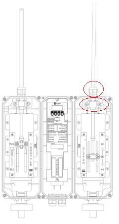
9 H102 Series Control Head H102 Forward Console H102A AFT Console 9
10 Control Head H102 / H102A Keypad 1) Station Select This button is for setting the control station to be in command. Power up default: Station 1 Station Lock MUST be deactivated & control handles MUST be place In neutral before station control can be transfer 2) Station Lock This feature will lock the station in command and will not allow transfer of control to any other station. Power up default: Station 1 Press to deactivated, no light, and press again to activate, lighted. 3) Port Override This feature will allow the port handle control of throttle WITHOUT activating the gear box. Control handle MUST be place in neutral. Press the button and the light is on. Move the pot handle into the clutch detent, gear box should not activate. Moving the leer further will start to increase the engine rpm. Move control lever back to neutral and press button, light off. This feature is usefully for operating PTO off the engine 4) Stbd Override This feature will allow the starboard handle control of throttle WITHOUT Activating the gear box. Control handle MUST be place in neutral. Press the button and the light is on. Move the port handle into the clutch detent, gear box should not activate. Moving the lever further will start to increase the engine rpm. Move control lever back to neutral and press button, light off. 5)Sync Mode This allows control of a twin engine with one control handle. Power up default: Starboard Handle. 6)Dim This allows the dimming of the LED lights on the keypad. Power up default: Full brightness Press, press, press, press, press to get the required brightness. 10
11 H102 Series Control Head Main board on Control Head 11
12 H102 Series Control Head H102 Series Dimension Mounting Hole Dimension 12
13 KC102 Series Engine Control System Chapter 2 A102 ACTUATOR UNIT 13

14 A102 ACTUATOR UNIT 14
15 2.A102 Actuator Unit 2.1 The A102 actuator is made up of three module, They are Throttle module, ECU module & Clutch module. 2.2 The throttle module contain the drive mechanism for the operation of the 43C push pull cable, the limit sensor and the feedback sensor 2.3 The clutch similar to the throttle module also contains the drive mechanism for the operation of the 43C push pull cable, the limit sensor and feedback sensor. 2.4 The ECU contains the software and the electronics for the control of the throttle & clutch module. All input and output wires connections are terminated here.!! CAUTION DO NOT INSTALL THE 43C PUSH PULL CABLE 2.5 Setting the dip switches. Switch ON OFF Default 1 STBD PORT OFF 2 Throttle Reverse Throttle Normal OFF 3 Clutch Reverse Clutch Normal OFF 4 SYNC STBD SYNC PORT OFF 5 Internal Memory External Memory OFF 6 Calibration & Test Enable Calibration & Test Disable OFF 15
16 A 102 Actuator error code display ON FND Error cause Buzzer Treatment ERR 1 Communication 1 ERR 2 Memory 2 ERR 3 Sensor 3 Check CAN BUS connector wiring Check motor broken Check Dip switch & Function set up Check Calibration data Check sensor connector wiring Check sensor broken ERR 4 Temperature 4 Check temperature of main board ERR 5 Motor ERR Check motor connector wiring Check motor broken A102 Actuator error display On A102 Actuator Error cause Buzzer Buzzer Pulse On Display Communication 1 ERR 1 Memory 2 ERR 2 Sensor 3 ERR 3 Temperature 4 ERR 4 Clutch Motor 5 ERR 5 Throttle Motor 6 ERR 6 On H102/ H102A Control Head *A1=PORT *A2=STBD Error cause Buzzer Buzzer Pulse On Display Communication 1 A1ER1 / A2ER1 Memory 2 A1ER2 / A2ER2 Sensor 3 A1ER3 / A2ER3 Temperature 4 A1ER4 / A2ER4 Clutch Motor 5 A1ER5 / A2ER5 Throttle Motor 6 A1ER6 / A2ER6 16
17 A 102 Actuator unit ECU Module 17

18 A 102 Actuator unit ACTUATOR PARTS 18
19 A 102 Actuator unit Emergency override operation 1.Pull down semi-circular handle fully. 2.Control by turning knob. 3.Push back semi-circular handle into slot fully(2 clicks) 4.Reset power supply. 19
20 Mount on the panel A102 ACTUATOR Dimension Mounting Holes Dimension 20
21 KC102 Series Engine Control System Chapter 3 SINGLE LINE CABLING & WIRE TERMINATION 21
22 Engine Room Wheel House Cabling 22
23 Set SW3 switch to ON position for last station Control Head Example) If station 2 is last Control Head, set SW3 switch to ON position. Install terminal link at terminal R ON position for last station Actuator Example) If PORT Actuator is last Actuator install a terminal link at terminal R ON position. Wire Termination 23
24 Cabling & Wire Termination Main board on Control Head 24
25 Cabling & Wire Termination ECU Module 25
26 KC102 Series Engine Control System Chapter 4 POWER UP SYSTEM & INITIAL CHECKS 26
27 4.Power up system and Initial checks 1.1 Upon Power up, Station 1 control head will a) Beep b) Station Select light flashing c) Station Lock light steady 1.2 Press Station select button on Station 1 a) Beeping stop b) Station Select light steady c) Station Lock light steady 1.3 Check that the actuator unit is displaying the correct Port / Stbd unit 1.4 Control system is now ready for final adjustment. 1.5 If error occurs refer to manual chapter 4 for trouble shooting. 27
28 A102 Actuator Error Code On Display Error cause Buzzer Treatment ERR 1 Communication 1 ERR 2 Memory 2 ERR 3 Sensor 3 Check CAN BUS connector wiring Check motor broken Check Dip switch & Function set up Check Calibration data Check sensor connector wiring Check sensor broken ERR 4 Temperature 4 Check temperature of main board ERR 5 Motor ERR Check motor connector wiring Check motor broken A102 Actuator error code display on A102 Actuator Error cause Buzzer Buzzer Pulse On Display Communication 1 ERR 1 Memory 2 ERR 2 Sensor 3 ERR 3 Temperature 4 ERR 4 Clutch Motor 5 ERR 5 Throttle Motor 6 ERR 6 A102 Actuator error code display on H102/H102A Control Head *A1=PORT *A2=STBD Error cause Buzzer Buzzer Pulse On Display Communication 1 A1ER1 / A2ER1 Memory 2 A1ER2 / A2ER2 Sensor 3 A1ER3 / A2ER3 Temperature 4 A1ER4 / A2ER4 Clutch Motor 5 A1ER5 / A2ER5 Throttle Motor 6 A1ER6 / A2ER6 28
29 On Display H102/H102A Control Head Error Code Error cause Buzzer Treatment Err 1 Communication 1 Err 2 Memory 2 Err 3 Sensor 3 Check CAN BUS connector wiring Check motor broken Check Dip switch & Function set up Check Calibration data Check sensor connector wiring Check sensor broken Err 4 Temperature 4 Check temperature of main board Error code display on A102 Actuator *H1=Station 1 *H2=Station 2 *H3=Station 3 *H4=Station 4 Error cause Buzzer Buzzer Pulse On Display Communication 1 H1ER1 / H2ER1 / H3ER1 / H4ER1 Memory 2 H1ER2 / H2ER2 / H3ER2 / H4ER2 Sensor 3 H1ER3 / H2ER3 / H3ER3 / H4ER3 Temperature 4 H1ER4 / H2ER4 / H3ER4 / H4ER4 Error code display on H102/ H102A Control Head *H1=Station 1 *H2=Station 2 *H3=Station 3 *H4=Station 4 Error cause Buzzer Buzzer Pulse On Display Communication 1 H1ER1 / H2ER1 / H3ER1 / H4ER1 Memory 2 H1ER2 / H2ER2 / H3ER2 / H4ER2 Sensor 3 H1ER3 / H2ER3 / H3ER3 / H4ER3 Temperature 4 H1ER4 / H2ER4 / H3ER4 / H4ER4 29
30 KC102 Series Engine Control System Chapter 5 Installing the 43C Push Pull Cable 30
31 5.Installing the 43C Push pull cable 5.1 Power off supply to the system. 5.2 Install the 43C push pull cable on the throttle module & clutch module of the Port actuator unit. 5.3 Power up the system and check the 43C cable to the port engine Governor lever is the correct direction. 5.4 If the direction is reverse, then switch off power. Set DIP switch 2 to ON on Port actuator unit 5.5 Switch on power and check if direction is correct. 5.6 Connect the 43C cable to the Port engine governor and gear box. Use the 43C connection kit provided. 5.7 Install the 43C push pull cable on the throttle & clutch module of the Starboard actuator unit. 5.8 Power up the system and check the 43C cable to the starboard engine governor lever is the correct direction. 5.9 If the direction is reverse, then switch off power. Set DIP switch 2 to ON on Stbd actuator unit Connect the 43C cable to the Stbd engine governor and gear box. Use the 43C connection kit provided Connect the 43C cable to the Stbd engine governor and gear box. Use the 43C connection kit provided 31
32 32
33 KC102 Series Engine Control System Chapter 6 Throttle Module Clutch Module Stroke Adjustment 33
34 6.Throttle module & Clutch module stroke adjustment 6.1 On the A102 actuator unit, Set DIP switch 6 to ON 6.2 Power up system. Press Select on station1 to stop the buzzer. 6.3 Press S1 until test Press S4, display shows TH-UP (Throttle distance data, mm) 6.4 Press S4, Display shows data for throttle position. Use the manual override control and move throttle to max. Record reading as 4-xx 6.5 Press S4, save to Throttle up distance 6.6 Display shows data for throttle position TH-DN. Use the manual override control and move throttle to min. Record reading as 3-xx 6.7 Press S4, save to Throttle down distance 6.8 Display shows data for clutch position CL-UP Use the manual override control and move clutch to fully up. Record reading as 2-xx 6.9 Press S4, save to Clutch up distance 6.10 Display shows data for clutch position CL-DN Use the manual override control and move clutch to fully down. Record reading as 1-xx 6.11 Press S4, save to Clutch down distance 6.12 Press S2 until END, press S4(Actuator may move) 34
35 KC102 Series Engine Control System Chapter 7 RESET TO FACTORY DEFAULT 35
36 7.Reset to Factory Default 7.1 DIP switch 6 On 7.2 Press S1 until Funct 7.3 Press S4 to enter 7.4 Press S2 until A-SET 7.5 Press and hold S4 for 02s with beep sound and release. 7.6 Display shows END 7.7 The software is now reset to factory default. 36
37 KC102 Series Engine Control System Chapter 8 A102 Actuator Function List Clutch forward distance Factory default F01 F ~ ~ 37 Clutch Forward distance set(mm) Minimum: 20mm Maximum: 37mm Make sure Clutch Reverse/Normal selection key ON or OFF on Dip switch 3 Clutch reverse distance Clutch Reverse distance set(mm) Minimum: 20mm Maximum: 37mm Make sure Clutch Reverse/Normal selection key ON or OFF on Dip switch 3 Throttle maximum limit range F03 F ~ ~ 30 Throttle maximum limit range set(mm) Minimum: 50mm Maximum: 75mm Make sure Throttle Reverse/Normal selection key ON or OFF on Dip switch 2 Throttle start point Throttle start point set(mm) Minimum: 00mm Maximum: 30mm Make sure Throttle Reverse/Normal selection key ON or OFF on Dip switch 2 Neutral delay time F ~ 50 Neutral delay time set Minimum: 10(1.0 sec) Maximum: 50(5.0 sec) 37
38 Throttle delay time F ~ 30 Throttle delay time set Minimum: 10(1.0 sec) Maximum: 30(3.0 sec) Crash stop F ~ 15 Clutch delay can occur set a fixed time control Minimum: 00(0 sec) Maximum: 15(15 sec) Crash stop to travel time F ~ 20 On clutch delay ready, delay terminated time by movement Minimum: 03(0.3 sec) Maximum: 20(2.0 sec) Main board temperature F ~ 70 Actuator main board s temperature set Minimum: 40(40 degree) Maximum: 70(70 degree) Single / Dual mode 0 Single Mode F Dual Mode Make sure station STBD/PORT selection key ON or OFF on Dip switch 1 Make sure SYNC. STBD/ PORT selection key ON or OFF on Dip switch 4 38
39 WARRANTEE CERTIFICATION This product is passed KINGS MARINE CO., LTD s strict quality test. If there is defect of manufacturing or abnormal detection within warrantee period, please contact our Agent or Distributor with this Warrantee Certification. WARRANTEE CLAUSE 1. The Warrantee period, we can guarantee, is one(1) year from your purchasing date 2. Warrantee Exception Clause - Warrantee period is expired. - Any kinds of Mal-function or defection caused by Modification or Repair without KINGS MARINE s permission. - Any kinds of Mal-function, Defection, or External damage, caused by operator - Any kinds of Mal-function, Defection, caused by using spare part from Non-Authorized Distributor or Agent. - Any kinds of Mal-function, Defection, caused by not following Warnings or Cautions mentioned on this manual. - Any kinds of Mal-function, Defection caused by Force Majeur, like Fire, Flood. - Without presentation of this Warrantee Certification. 3. Other - Any kinds of Warrantee Certification without authorized Signature is out of validity Manufacturer KINGS MARINE CO., LTD Room 202, Manufacture Unit A, Jeon-Nam Techno Park, Hoduri 114, Haeryong meon, Suncheon City, Jeon-Nam Province, KOREA Tel: Fax: kingsmarine@daum.net MADE INin KOREA Product Model AUTHORIZED SIGNATURE KC102 Series Engine Control System A102 / H102 / H102A 39
Section 55 Chapter 6
 Section 55 Chapter 6 REMOTE HYDRAULICS CONTROLLER Calibration and Fault Codes 6-12880NH TABLE OF CONTENTS REMOTE HYDRAULICS CONTROLLER CALIBRATION... 55-5 Requirements For Calibration... 55-5 Aux Set Main
Operations Manual. Put the Pleasure Back into Boating! MANOP6000SEM01 Revision A
 Operations Manual Put the Pleasure Back into Boating! MANOPSEM1 Revision A Notice to Boat Manufacturer, Installer, and Consumer Throughout this manual, warnings are used to alert the installer/operator
GLENDINNING ONTROL QUICK REFERENCE GUIDE. (see Operations Manual for more detailed information)
") GLENDINNING EL E C T NGINE C R O N I C ONTROL QUICK REFERENCE GUIDE (see Operations Manual for more detailed information) EEC QUICK REFERENCE GUIDE - TABLE OF CONTENTS SYSTEM STARTUP CRUISE MODE WARM UP
GLENDINNING EL E C T NGINE C R O N I C ONTROL QUICK REFERENCE GUIDE (see Operations Manual for more detailed information) EEC QUICK REFERENCE GUIDE - TABLE OF CONTENTS SYSTEM STARTUP CRUISE MODE WARM UP
KE-4 Installation/Operation Instruction Manual FT033
 KE-4 Installation/Operation Instruction Manual FT033 Electronic Control System Electronic Control System Thumb Tab Guide Trolling Module Handheld Control Engine Synchronization Trolling Module Handheld
Table of Contents Operations Overview CONTROL HEAD OPERATIONS AND KEYPAD OPERATIONS AT-A-GLANCE...pg 1 System Startup EXPLAINS THE PROCESS OF
 Complete Controls Operators Guide v0. Table of Contents Operations Overview CONTROL HEAD OPERATIONS AND KEYPAD OPERATIONS AT-A-GLANCE........................................pg System Startup EXPLAINS THE
MANUFACTURING COMPANY LIMITED TH Street Surrey, B.C. Canada V3W 0A6 Telephone: (604) Fax: (604)
 Fax: (604)") ISO 9001 CERTIFIED MANUFACTURIN COMPANY LIMITED 8238-129 TH Street Surrey, B.C. Canada V3W 0A6 Telephone: (604) 572-3935 Fax: (604) 590-8313 http://www.kobelt.com MIHTY MARINER ENINE CONTROLS INSTALLATION
ISO 9001 CERTIFIED MANUFACTURIN COMPANY LIMITED 8238-129 TH Street Surrey, B.C. Canada V3W 0A6 Telephone: (604) 572-3935 Fax: (604) 590-8313 http://www.kobelt.com MIHTY MARINER ENINE CONTROLS INSTALLATION
Automated Control Electronics (ACE ) System Operation and Diagnostics
 System Operation and Diagnostics") Commercial Products Automated Control Electronics (ACE ) System Operation and Diagnostics PART NO. 98962SL This page is intentionally blank. Table of Contents Introduction... 1 Controller Operation and
Commercial Products Automated Control Electronics (ACE ) System Operation and Diagnostics PART NO. 98962SL This page is intentionally blank. Table of Contents Introduction... 1 Controller Operation and
KE-6 ELECTRONIC CONTROL SYSTEM INSTRUCTION MANUAL
 KE-6 ELECTRONIC CONTROL SYSTEM INSTRUCTION MANUAL TABLE OF CONTENTS INTRODUCTION-------------------------------------------------------------------------------------------------------------1 SAFETY PRECAUTIONS
Throttle-by-wire. MasterCraft Technical Training Vonore, Tennessee USA. A MasterCraft Technical Services Publication
 Throttle-by-wire MasterCraft Technical Training Vonore, Tennessee USA A MasterCraft Technical Services Publication MasterCraft University 2008-2009 Throttle-by-wire Page 1 Electronic Throttle Control Description
Indian Speedometer and Body Control Module Service Tool Users Guide
 Indian Speedometer and Body Control Module Service Tool Users Guide Installing speedometer software to your computer 1. Go to the Indian Motorcycle Website: WWW. Indianmotorcycle.com 2. Log in to Service
INSTALLATION AND OPERATION INSTRUCTION
 INSTALLATION AND OPERATION INSTRUCTION ATi Max 2-1/2-6, 65-150mm Install the ATi Max valve either in the supply or return pipework for the unit. It is recommended that a strainer be installed prior to
Operating manual and installation instructions ENGLISH. Electronic engine remote control. Copyright 2001 Vetus den Ouden n.v.
 Operating manual and installation instructions ENGLISH Electronic engine remote control Copyright 00 Vetus den Ouden n.v. Schiedam Holland Contents Introduction... General conditions of use... Operating....
EQUIPMENT - MAIN BODY 7-1 SECTION 7 EQUIPMENT CONTENTS
 EQUIPMENT - MAIN BODY 7-1 SECTION 7 EQUIPMENT CONTENTS Engine Immobiliser System...7-1 Exterior Lights...7-2 Combination Meter...7-2 Smart Wiring System (SWS)...7-3 General Information...7-3 Functions
MARINE PROPULSION CONTROL
 PRODUCT BULLETIN SB-8504B MARINE PROPULSION CONTROL ELECTRONIC LOGIC AND CONTROL PANEL Type MPC-E9 Control Panel APPLICATION Propulsion controls for small and large vessels with fixed pitch propellers,
CRUISE CONTROL SPEED LIMITER Rev. 4.0
 INSTALLATION f MANUAL CRUISE CONTROL & SPEED LIMITER AP900Series SL900Series 231.0004530 Rev. 4.0 1 2 CONTENTS: Chapters 1 Kit contents. 3 2 Tools required 4 3 Electronics module location... 5 4 Input
»Plug&Play«Paddle Shift System Kit - Porsche 997 GT3 Cup
 »Plug&Play«Paddle Shift System Kit - Porsche 997 GT3 Cup FUNCTIONAL DESCRIPTION AGENDA 1. Introduction 2. System overview 2.1 Central Unit (GCU) 2.2 Valve block 3V 2.3 Shift cylinder 2.4 Blip cylinder
UPS Wizard User s Manual
 1. The communication cable M2502: This is a special designed cable for the communication of UPS with your PC; only connecting with the correct cable, the PC can detect the UPS. 2. The main window of the
EDG6000 Electronic Digital Governor
 INTRODUCTION GAC s digital governor is designed to regulate engine speed on diesel and gaseous fueled engines. When paired with a GAC actuator the EDG is a suitable upgrade for any mechanical governor
Please refer to the 2019 IS 300/350 Quick Guide or Navigation Owner s Manual for more information on Remote Touch operations.
 Lexus Personalized Settings Your vehicle includes a variety of electronic features that can be programmed to your preferences. The programming of these features is performed once at no charge by your Lexus
CRUISE CONTROL SPEED LIMITER. SL900Series. Dealer address details: Rev. 3.0
 USER GUIDE f CRUISE CONTROL & SPEED LIMITER AP900Series SL900Series Dealer address details: 11 231.0005010 Rev. 3.0 1 2 CONTENTS: 1 Product variants... 2 2 Cruise Control Safety Features. 3 3 Operating
 TRACTION CONTROL SYSTEM 1996 Toyota Supra 1995-96 BRAKES Traction Control Supra DESCRIPTION Toyota Traction Control (TRAC) system controls engine torque and braking of the driving wheels. TRAC system is
CONSOLE MANAGEMENT CONTROLLER
 CONSOLE MANAGEMENT CONTROLLER Installation Card For Door Lock Kit Read Instructions Completely Before Beginning Installation Procedures NOTICE Printed on recycled paper 00 Compaq Information Technologies
I. CONNECTING TO THE GCU
 I. CONNECTING TO THE GCU GCU7 and newer units use CAN BUS to connect to the computer so special interface is needed. GCU Interface uses FTDI drivers which are usually already installed by default. If you
ELECTRONIC ENGINE CONTROLS. (Model 6525)
") ELECTRONIC ENGINE CONTROLS (Model 6525) INSTALLATION MANUAL February 2012 ELECTRONIC ENGINE CONTROLS INSTALLATION INSTRUCTIONS Table of Contents 1. GENERAL INFORMATION... 1-1 2. SYSTEM COMPONENTS... 2-1
ELECTRONIC ENGINE CONTROLS (Model 6525) INSTALLATION MANUAL February 2012 ELECTRONIC ENGINE CONTROLS INSTALLATION INSTRUCTIONS Table of Contents 1. GENERAL INFORMATION... 1-1 2. SYSTEM COMPONENTS... 2-1
Tension Control Inverter
 Tension Control Inverter MD330 User Manual V0.0 Contents Chapter 1 Overview...1 Chapter 2 Tension Control Principles...2 2.1 Schematic diagram for typical curling tension control...2 2.2 Tension control
QUICKSTART ESSENTIALS
 QUICKSTART ESSENTIALS QS007-01 WORKSURFACE HEIGHT ADJUSTMENT Sit to Stand EON PHOSPHATE CONTROL PANEL GAS SPRING MODEL ACTUATOR MODEL For height adjustment pull lever on gas spring model or use UP/DOWN
CRUISE CONTROL SPEED LIMITER. SL900Series. Dealer address details: C Rev. 7.0
 INSTALLATION f MANUAL CRUISE CONTROL & SPEED LIMITER AP900Series SL900Series Dealer address details: 35 231.000453C Rev. 7.0 1 2 NOTES: CONTENTS: Chapters 1 Kit contents. 3 2 Tools required 4 3 Electronics
Smart Actuator Installation & Operation Manual v3.8a. Complete Controls by Glendinning
 Smart Actuator Installation & Operation Manual v3.8a Complete Controls by Glendinning WARNING: DISCONNECT SYSTEM S GROUND AND BONDING BEFORE ANY WELDING ACTIVITY ON BOARD VESSEL! SML-SMACT-MAN_v3.8A Glendinning
IGA225 Integrated Governor & Actuator
 INTRODUCTION GAC s integrated digital governor and actuator is designed to regulate engine speed on diesel and gaseous fueled engines. The IGA is a suitable upgrade for any mechanical governor system that
GCU-10. Automatic Engine Control Unit Operators Manual
 GCU-10 Automatic Engine Control Unit Operators Manual KUTAI ELECTRONICS INDUSTRY CO., LTD. TEL : +886-7-8121771 FAX : +886-7-8121775 Website : www.kutai.com.tw Headquarters : No.3, Lane 201, Chien Fu St.,
Service Manual. Extractor Model XR28QP. For The. For: Troubleshooting Adjustments
 Service Manual For The X Ride 28 Rider Extractor Model XR28QP For: Training Troubleshooting Adjustments Contents 1 Cautions ------------------------------------------------------------------------------
TEL: G&C Electronics CC E. T.
 TEL: +27 21 448 6774 G&C Electronics CC FAX: +27 21 447 7794 E. T. CK 89/31531/23 E-mail : etsystems@icon.co.za Internet: www.et.co.za 15 Nelson Road P.O. Box 34524 Observatory Groote Schuur Cape Town
For the most current information, visit the Roadranger web site at
 Eaton Fuller Automated Transmissions AutoShift Gen II Models Quick Reference Guide TRMT-0062 March 2000 For the most current information, visit the Roadranger web site at www.roadranger.com General Warnings:
e-ask electronic Access Security Keyless-entry
 e-ask electronic Access Security Keyless-entry Multiplex System Multiplex System Installation & Instructions (UM15 ~ 22272-03) Table of Contents Introduction... 1 Standard e-fob Operation and Features...
PRESSURE GOVERNOR, ENGINE MONITORING, AND MASTER PRESSURE DISPLAY MODEL: TCA100
 Document Number: XE-TCA1PM-R0A TCA100 Rev0511 PRESSURE GOVERNOR, ENGINE MONITORING, AND MASTER PRESSURE DISPLAY MODEL: TCA100 FIRE RESEARCH CORPORATION www.fireresearch.com 26 Southern Blvd., Nesconset,
V4(V7)-ABFW-EPN16 Actuated Wafer type butterfly valves
-ABFW-EPN16 Actuated Wafer type butterfly valves") V4(V7)-ABFW-EPN16 Actuated Wafer type butterfly valves FEATURES PRODUCT DATA Cast Iron (V4) or SUS304 (V7) Wafer Body Centric butterfly valve with elastomer liner Wide DN-range (DN 50 DN600) For On/Off
V4(V7)-ABFW-EPN16 Actuated Wafer type butterfly valves FEATURES PRODUCT DATA Cast Iron (V4) or SUS304 (V7) Wafer Body Centric butterfly valve with elastomer liner Wide DN-range (DN 50 DN600) For On/Off
SHIFT SELECTOR OPERATION AND CODE MANUAL
 SHIFT SELECTOR OPERATION AND MANUAL How to use the shift selector to read oil level and diagnostic codes on 3000/4000 Series Allison transmissions P.O. Box 894, Speed Code 462-470-PF3 Indianapolis, Indiana
DIAGNOSIS SYSTEM DESCRIPTION CHECK ENGINE WARNING LIGHT CHECK
 FI146 EFI SYSTEM (3VZE) DIAGNOSIS SYSTEM DESCRIPTION The engine (engine and ECT) ECU contains a builtin, selfdiagnosis system which detects troubles within the engine signal network and flashes the warning
Z155, ST3000 Autopilot Service Manual
 D296 Z155, ST3000 Autopilot Service Manual Warning CE Marking of Equipment/Replacement Parts If the Autohelm equipment under repair, test, calibration, installation or setting to work carries the European
2001 Chevrolet Corvette ACCESSORIES & EQUIPMENT Remote Keyless Entry Systems - Corvette
 DESCRIPTION 2001 ACCESSORIES & EQUIPMENT Remote Keyless Entry Systems - Corvette Remote Keyless Entry (RKE) system is controlled by Remote Function Actuation (RFA) system. Transmitter allows remote control
PBA Series Prelube Controls
 VARNA Products Engineered Innovation PBA Series Prelube Controls Simple, Compact, Industrial Full featured control for running prelube from the control or from a remote station Easy internal wiring connections
PRESSURE GOVERNOR, ENGINE MONITORING, AND MASTER PRESSURE DISPLAY MODEL DDA100
 PRESSURE GOVERNOR, ENGINE MONITORING, AND MASTER PRESSURE DISPLAY MODEL DDA100 1 CONTENTS Table of Contents CONTENTS... 2 INTRODUCTION... 4 Overview... 4 Features... 4 GENERAL DESCRIPTION... 5 2 List of
Windows and mirrors ELECTRIC WINDOWS. Raise and lower. One-touch operation. Automatic window drop for door opening
 Windows and mirrors ELECTRIC WINDOWS WARNINGS Before operating power windows you should verify they are free of obstructions and ensure that children and or pets are not in the proximity of window openings.
PRIME MOVER CONTROLS INC. MARINE PROPULSION CONTROLS. Series MPC-CP SYSTEM
 PRODUCT BULLETIN SSB 001-550-300 MARINE PROPULSION S Series 550-300 MPC-CP SYSTEM TYPE MPC-CP SYSTEM FOR VESSELS WITH LABLE PITCH PROPELLERS Aesthetic design Ergonomic Versatile Economical Electronic engine
Fuller Automated Transmissions TRDR0082
 Driver Instructions Video Instruction Available Instructional videos are available for download at no charge at roadranger.com Videos are also available for purchase. To order, call 1-888-386-4636. Ask
CRUISE CONTROL SYSTEM
 CRUISE CONTROL SYSTEM 1994 Toyota Celica 1994 ACCESSORIES & EQUIPMENT Toyota Motor Sales, U.S.A., Inc. - Cruise Control Systems Celica DESCRIPTION Cruise control system consists of Cruise Control Electronic
Please refer to the 2019 Lexus NX 300h Quick Guide or Owner s Manual for detailed information on Remote Touch operations. STEP
 Lexus Personalized Settings Your vehicle includes a variety of electronic features that can be programmed to your preferences. The programming of these features is performed once at no charge by your Lexus
INSTALLATION MANUAL SPECTRUM BRAKE CONTROL
 INSTALLATION MANUAL 51170 SPECTRUM BRAKE CONTROL TABLE OF CONTENTS Controls & Components Tools List Before You Begin Wiring Wiring Diagram Mounting the LED Display Rotary Knob Wiring the Plug Connector
1. Disclaimer Warnings Introduction Display and Commands... 5
 1. Disclaimer... 1 2. Warnings... 2 2.1. Welding... 2 3. Introduction... 3 4. Display and Commands... 5 4.1. Status Display on LCD... 5 4.1.1. Control Mode... 6 4.1.2. Bowl Mode... 6 4.1.3. Engine Mode...
Technical Instructions Flowrite 599 Series SKD6xU Electronic Valve Actuators 24 Vac Proportional Control Description Features Application
 Document No. 155-180P25 Flowrite 599 Series SKD6xU Electronic Valve Actuators 24 Vac Proportional Control Description The Flowrite 599 Series SKD6xU Electronic Valve Actuators require a 24 Vac supply and
CONTENTS INTRODUCTION
 CONTENTS INTRODUCTION 2 Lubrication 3 Physical dimensions 4 Technical specifications 5 STANDARD INSTALLATION KIT 6 WARNINGS 7 INSTALLATION OF THE UNIT 8 Initial preparations and mounting the base plate
User Instructions for WRC1021D. Doc
 User Instructions for WRC1021D Doc. 0001-5989 CONTENTS 1.0 INTRODUCTION TO THE WRC1021D... 2 2.0 FUNCTIONAL DESCRIPTION... 3 3.0 POTENTIOMETERS, SWITCHES AND INDICATORS... 5 4.0 CALIBRATION AND START-UP
Water Specialist EE Control Valve Programming and Cover Drawing Manual
 Water Specialist EE Control Valve Programming and Cover Drawing Manual Page 2 EE Man u al EE Man u al Page 3 Table of Contents EE Front Cover and Drive Assembly... 4 Regeneration and Error Screens, Button
INSTALLATION, OPERATION AND TROUBLESHOOTING
 INSTALLATION, OPERATION AND TROUBLESHOOTING MM9000 - CLEAR COMMAND USER MANUAL MARINE PROPULSION SYSTEMS COPYRIGHT Released by After Sales dept. Data subject to change without notice. We decline all responsibility
MULTI FUNCTIONAL COUNT CHECKER MODEL Poka Patrol CNA-4mk3
 MULTI FUNCTIONAL COUNT CHECKER MODEL Poka Patrol CNA-4mk3 OPERATING INSTRUCTION Poka Patrol CNA-4mk3 Poka Patrol CNA-4mk3 To use this product properly and safely, please read this manual carefully before
GENERAL INFORMATION MECHANICAL INSTALLATION PRESSURE INDEPENDENT VALVES 2-1/2"-10" MVP INSTALLATION & OPERATION INSTRUCTIONS UNION CONNECTIONS
 GENERAL INFORMATION INSTALLATION & OPERATION INSTRUCTIONS 1. Clean the lines upstream of valve particles larger than 1/16" diameter (welding slag, pipe scale and other contaminants). Griswold Controls
Actuators for modulating control AME 110 NL, AME 120 NL
 Actuators for modulating control AME 110 NL, AME 120 NL Description The actuators are used together with automatically balanced combination valve type AB-QM for DN 10-32. The actuator can be used with
Overvoltage Suppression F7 Drive Software Technical Manual
 Overvoltage Suppression F7 Drive Software Technical Manual Software Number: VSF11015X, Drive Models: CIMR-F7UXXXXXX-062, CIMR-F7U40750F-145. Document Number: TM.F7SW.062, Date: 09/17/2010, Rev: 10-09 This
2003 CVT when used with 2.2L L61 engine in the Saturn ION TRANSMISSION DIAGNOSTIC PARAMETERS
 TCM Memory ROM P0601 The code is designed to verify ROM checksum at key up. TCM Not Programmed P0602 The code is designed to verify that the TCM has been programmed. TCM Long Term Memory Reset P0603 This
Operating Instructions. Angle Seat Control Valve. Type 7020
 Operating Instructions Angle Seat Control Valve Type 7020 With: Digital Positioner Type 8048 Electro-pneumatic Positioner Type 8047 Pneumatic Positioner Type 8047 Version: 02/2006 Manual-7020e.doc Art.-No:
CRUISE CONTROL SYSTEM
 Negative (-) Battery Terminal CRUISE CONTROL CRUISE CONTROL SYSTEM Cable System name METER / GAUGE SYSTEM D033496E01 CRUISE CONTROL SYSTEM PRECAUTION 1 1. DISCONNECT AND RECONNECT CABLE OF NEGATIVE BATTERY
Wind display type WSDI-2
 USER s MANUAL/INSTALLATION NOTE Wind display type WSDI-2 Input and wiring Mounting Document no.: 4189350032C Table of contents 1. INTRODUCTION... 3 UNPACKING... 3 2. INPUT AND WIRING INSTRUCTION... 4 3.
TTT802 Gearshift Controller, Part # R1N-S (Standard), -P (Paddleshift)
, -P (Paddleshift)") First, Sign and Date Bln 2009-03-9 Updated, Sign and Date Bln 200-04-29 (0) User Manual TTT802 Gearshift Controller Firmware for R--N-2- TTT802 Gearshift Controller, Part # 2-620-9-RN-S (Standard), -P
First, Sign and Date Bln 2009-03-9 Updated, Sign and Date Bln 200-04-29 (0) User Manual TTT802 Gearshift Controller Firmware for R--N-2- TTT802 Gearshift Controller, Part # 2-620-9-RN-S (Standard), -P
Automatic Genset Controller, AGC-4 Display readings Push-button functions Alarm handling Log list
 OPERATOR'S MANUAL Automatic Genset Controller, AGC-4 Display readings Push-button functions handling Log list DEIF A/S Frisenborgvej 33 DK-7800 Skive Tel.: +45 9614 9614 Fax: +45 9614 9615 info@deif.com
ACS LED SIGNALLING UNIT LINEAR SENSOR CALIBRATION. AS-i module / multi-voltage modules version
 ACS LED SIGNALLING UNIT LINEAR SENSOR CALIBRATION AS-i module / multi-voltage modules version TABLE OF CONTENTS GENERAL 2 LOCKING/UNLOCKING THE KEYBOARD 2 CALIBRATION 2 MANUAL CALIBRATION FACILITY: 3 AUTOMATIC
Commander 15i Container and Pallet Loader. Property of American Airlines
 Commander 15i Container and Pallet Loader Section 2. Operation BEFORE ATTEMPTING TO OPERATE OR MAINTAIN THE VEHICLE, COMPLETELY READ AND UNDERSTAND THE OPERATION AND MAINTENANCE MANUAL, INCLUDING ALL DANGER,,
LIPPERTCOMPONENTS, INC.
 LIPPERTCOMPONENTS, INC. SCHWINTEK INWALL SLIDEOUT SYSTEM OPERATION AND SERVICE MANUAL Contents I. Controls 1-1 System components 1 1-1A versions C1 & C2 2 1-2 Motor wiring harness connections 3 1-3 Extend
DTS SLIDING GATE MOTOR INSTALLATION MANUAL. DTS 600 Elite with SL150 PCB DTS SECURITY P.O.BOX 3399 EDENVALE 1610 TELEPHONE
 DTS SLIDING GATE MOTOR INSTALLATION MANUAL DTS 600 Elite with SL150 PCB DTS SECURITY P.O.BOX 3399 Base plate-mounting EDENVALE instructions 1610 TELEPHONE 086 1000 387 Spartan +2711 392 5540 (H/O) Pretoria
AutoControl Pressure Governor
 AutoControl Governor OPERATION and INSTALLATION MANUAL MODEL WSD-100: Cummins Electronics Engines-ISB, ISC, ISL, ISM WSD-200: DDEC electronics engines-series 50 and Series 60 WSD-240: DDEC Series 40 engines
1999 Toyota RAV ACCESSORIES & EQUIPMENT Cruise Control Systems - RAV4
 1999 ACCESSORIES & EQUIPMENT Cruise Control Systems - RAV4 DESCRIPTION WARNING: Deactivate air bag system before performing any service operation. See AIR BAG RESTRAINT SYSTEMS article. DO NOT apply electrical
Service Bulletin Buses
 Prevost Saint-Nicolas, Quebec, Canada Buses No. Release Page Date Group 6.2010 432 00 1( 9 ) Gear Selector Control Module (GSCM) MID 223, Diagnostic Trouble Code (DTC), Guide Gear Selector Control Module
SAX Electronic Valve Actuator
 Document No. 129-561 SAX Electronic Valve Actuator Product Description The SAX Electronic Valve Actuator requires a 24 Vdc or 24 Vac, Class 2, supply signal to control a Flowrite 599 Series valve or a
MVE2XX. Globe Valves Actuators. Power. Model Force (N)
") Globe Valves Actuators MVE2XX Model Force (N) supply Description MVE206 600 230Vac±10% long yoke, modulating/fl oating control MVE210 1000 230Vac±10% long yoke, modulating/fl oating control MVE215 1500
Globe Valves Actuators MVE2XX Model Force (N) supply Description MVE206 600 230Vac±10% long yoke, modulating/fl oating control MVE210 1000 230Vac±10% long yoke, modulating/fl oating control MVE215 1500
SureShift Transmission
 Issued 10-99 $2.50 SureShift Transmission Maintenance and Diagnostics Manual No. MM-9970 WE SUPPORT VOLUNTARY TECHNICIAN CERTIFICATION THROUGH TM Service Notes Service This Notes publication provides maintenance
OPERATION INSTRUCTIONS AND USER S MANUAL. Before you do it your way, please try it our way. i7700 Shift & Throttle System.
 OPERATION INSTRUCTIONS 79 SEVENTY NINE ISO 9001 AND USER S MANUAL www.seastarsolutions.com i7700 Shift & Throttle System Before you do it your way, please try it our way 2017 SeaStar Solutions. All Rights
Setup Tabs. Basic Setup: Advanced Setup:
 Setup Tabs Basic Setup: Password This option sets a password that MUST be entered to re-enter the system. Note: ProEFI can NOT get you into the calibration if you lose this password. You will have to reflash
MANUAL. SIMRAD FU25 and FU50 Steering Levers
 MANUAL SIMRAD FU25 and FU50 Steering Levers 20221065E English Simrad FU25 and FU50 Follow-up steering levers 2 20221065 / E Introduction Instruction Manual This manual is intended as a reference guide
Automated socks packaging machine PS-1
 English Manual Automated socks packaging machine PS-1 Contents 1. Introduction 2. Important safety instructions 3. PS-1 4. Installation of air supply 5. SwifTach Power Unit (SPU) module 6. Operations 7.
CPi. CoiL PACK IGNiTioN FOR AViATiON. For 4,6 and 8 cylinder 4 stroke applications. Please read the entire manual before beginning installation.
 1 CPi CoiL PACK IGNiTioN FOR AViATiON Coil pack (4 cylinder) Coil pack (6 cylinder) For 4,6 and 8 cylinder 4 stroke applications. Please read the entire manual before beginning installation. Software version
RCS-FT1 Control unit RCS-FC1. Cargo crane Radio control device (Specified low power radio type) Transmitter MODEL. Publication No.
 Transmitter MODEL. Publication No.") Publication No. W307-0061E 01 Cargo crane Radio control device (Specified low power radio type) Transmitter RCS-FT1 Control unit RCS-FC1 MODEL 2006 PRINTED IN JAPAN 0610 K Foreword Foreword This service
Publication No. W307-0061E 01 Cargo crane Radio control device (Specified low power radio type) Transmitter RCS-FT1 Control unit RCS-FC1 MODEL 2006 PRINTED IN JAPAN 0610 K Foreword Foreword This service
Flowrite EA 599 Series SKB/C/D 62UA Series Electronic Valve Actuator 24 Vac Proportional Control Advanced Features
 Flowrite EA 599 Series SKB/C/D 62UA Series Electronic Valve Actuator 24 Vac Proportional Control Advanced Features Technical Instructions Document No. 155-717 EA-599-18 SKB/C SKD Description The Flowrite
For system diagrams and component identification
 Pneumatic Symbols For system diagrams and component identification Contents Standards Actuators Basic symbols Valve symbol structure t Functional elements Flowlines Connections Conditioners and plant Pressure
DESCRIPTION & OPERATION
 ANTI-THEFT SYSTEM 1998 ACCESSORIES & EQUIPMENT General Motors Corp. - Anti-Theft System DESCRIPTION & OPERATION WARNING: Deactivate air bag system before performing any service operation. See AIR BAG RESTRAINT
Cirtix series Brushless Speed Controller manual For RS1/RS A/ Page - 1 -
 RS1/RS20602010A/100524 Page - 1 - Thank you for purchasing the Speed Passion Cirtix series electronic speed controller (ESC). High power systems for RC models can be very dangerous, so we strongly suggest
CRUISE CONTROL SYSTEM
 CRUISE CONTROL SYSTEM CONTROL SYSTEM PARTS LOCATION CRUISE CONTROL CRUISE CONTROL SYSTEM 1 ENGINE ROOM R/B AND J/B MAIN BODY ECU (INSTRUMENT PANEL J/B) B142328E05 2 CRUISE CONTROL CRUISE CONTROL SYSTEM
KEYLESS ENTRY SYSTEM & TIRE PRESSURE MONITOR ACCESSORIES & EQUIPMENT General Motors Corp. - Remote Keyless Entry System
 KEYLESS ENTRY SYSTEM & TIRE PRESSURE MONITOR 1998 ACCESSORIES & EQUIPMENT General Motors Corp. - Remote Keyless Entry System DESCRIPTION Remote Keyless Entry (RKE) system is controlled by Remote Function
Water Specialist EI Control Valve Programming and Cover Drawing Manual
 Water Specialist EI Control Valve Programming and Cover Drawing Manual Page 2 EI Man u al EI Man u al Page 3 Table of Contents EI Front Cover and Drive Assembly... 4 Regeneration and Error Screens... 5
# & XFI Chrysler Big Block ( A Series)/ Hemi/440RB Series Dual Sync Distributor
/ Hemi/440RB Series Dual Sync Distributor") 1 INSTRUCTIONS #305012 & 305013 XFI Chrysler Big Block (383-400A Series)/ Hemi/440RB Series Dual Sync Distributor Thank you for choosing products; we are proud to be your manufacturer of choice. Please
1 INSTRUCTIONS #305012 & 305013 XFI Chrysler Big Block (383-400A Series)/ Hemi/440RB Series Dual Sync Distributor Thank you for choosing products; we are proud to be your manufacturer of choice. Please
TRESHOLD SENSORS LOGIC PNEUMATIC COUNTERS TIMERS VALVES
 PNEUMATIC TIMERS N.C / N.O. PNEUMATIC COUNTERS with / VALVE PANEL MOUNTED PNEUMATIC COUNTERS LOJIC VALVES OR GATES TRESHOLD SENSORS LOGIC PNEUMATIC COUNTERS TIMERS VALVES LOGIC PNEUMATIC LOGIC VALVES
Installation & Programming Guide
 Installation & Programming Guide EMTouch & EMTouch Classic Style Electronic Lever Locksets EMTouch EMTouch Classic Style ASSA ABLOY, the global leader in door opening solutions What s in the Box 4a 4b
REMOTE KEYLESS ENTRY AND ANTI-THEFT SYSTEM
 SECTION 9T REMOTE KEYLESS ENTRY AND ANTI-THEFT SYSTEM Caution: Disconnect the negative battery cable before removing or installing any electrical unit or when a tool or equipment could easily come in contact
Technical Instructions. SQV Series Electromotive Valve Actuators. Document No
 Document No. 155-521 (For Use with 2-1/2-Inch to 6-Inch Pressure Independent Control Valves) Features Operating voltage: AC/DC 24V Application Control signals: 3-position, DC 0 to 10V, DC 4 to 20 ma Fail-safe
Lingenfelter NCC-002 Nitrous Control Center Quick Setup Guide
 Introduction: Lingenfelter NCC-002 Nitrous Control Center Quick Setup Guide The NCC-002 is capable of controlling two stages of progressive nitrous and fuel. If the NCC-002 is configured only for nitrous,
Automatic Electric Jack Leveling
 Contents Before You Level Your Coach 1 Caution Leveling System Operating Instructions -- Buttons and Operation 2 Lights & Function Indicators 2 Selecting A Site 2 Automatic Leveling 2 Manual Leveling 3
GM6B SERIES PTO INSTALLATION FOR GENERAL MOTORS 3600 CAB CHASSIS WITH ALLISON 1000 SERIES AUTOMATIC TRANSMISSION
 KEEP IN VEHICLE READ OPERATING INSTRUCTIONS INSIDE BEFORE OPERATING PTO GM6B SERIES PTO INSTALLATION FOR GENERAL MOTORS 3600 CAB CHASSIS WITH ALLISON 1000 SERIES AUTOMATIC TRANSMISSION Use this manual
KEYLESS OPERATION SYSTEM (KOS)
") 42B-1 GROUP 42B KEYLESS OPERATION SYSTEM (KOS) CONTENTS GENERAL INFORMATION 42B-2 42B-8 DOOR ENTRY FUNCTION 42B-8 KEYLESS ENTRY FUNCTION 42B-13 ENGINE STARTING FUNCTION (IMMOBILIZER FUNCTION) 42B-17 TIRE
42B-1 GROUP 42B KEYLESS OPERATION SYSTEM (KOS) CONTENTS GENERAL INFORMATION 42B-2 42B-8 DOOR ENTRY FUNCTION 42B-8 KEYLESS ENTRY FUNCTION 42B-13 ENGINE STARTING FUNCTION (IMMOBILIZER FUNCTION) 42B-17 TIRE
CRUISE CONTROL SPEED LIMITER
 Dealer address details: 39 INSTALLATION MANUAL CRUISE CONTROL & SPEED LIMITER AP900Ci SL900CiSeries 231.0005060 Rev. 1.0 f FOREWORD: This installation manual is written for installers with knowledge of
CHUBBSAFES EVOLVE INSTRUCTION MANUAL
 CHUBBSAFES EVOLVE INSTRUCTION MANUAL 1 Ref: BASS-0010-B/21.02.2014 Table of content 1- CHARACTERISTICS... 4 1-1 Models... 4 1-2 Dimensions & Weights... 4 1-3 Interior fittings (standard and optional)...
PRESSURE GOVERNOR, ENGINE MONITORING, AND MASTER PRESSURE DISPLAY MODEL: NYA100
 Document Number: XE-NYA1PM-R0A NYA100 Rev0908 PRESSURE GOVERNOR, ENGINE MONITORING, AND MASTER PRESSURE DISPLAY MODEL: NYA100 FIRE RESEARCH CORPORATION www.fireresearch.com 26 Southern Blvd., Nesconset,
DCS7 Water Softener - Product Manual
 pg. 0 Set Up Instructions for DCS7 Water Softener Inspect the packaging of the equipment to confirm that nothing was damaged during shipping. (Figure 1) Remove the resin tank(s) and valve(s) from the packaging.