DEPARTMENT OF THE ARMY TECHNICAL MANUAL OPERATOR S AND ORGANIZATIONAL TEST SETS, ELECTRON TUBE TV-7/U, TV-7A/U, TV-7B/U AND TV-7D/U
|
|
|
- Gavin Lawrence
- 6 years ago
- Views:
Transcription
1 TM DEPARTMENT OF THE ARMY TECHNICAL MANUAL OPERATOR S AND ORGANIZATIONAL MAINTENANCE MANUAL TEST SETS, ELECTRON TUBE TV-7/U, TV-7A/U, TV-7B/U AND TV-7D/U This copy is a reprint which includes current pages front Charges 6 and 7. HEADQUARTERS, DEPARTMENT OF THE ARMY 14 JUNE 1960
2 W A R N I N G Be careful not to contact high-voltage connections or the 115-volt ac input connections when replacing tubes in the test set. Voltages up to 300 volts ac may be encountered in this equipment. Serious injury or death may result from contact with these connections. DON T TAKE CHANCES!
3 Changes in force: C6 and C7 TM *C7 CHANGE NO. 7 HEADQUARTERS DEPARTMENT OF THE ARMY Washington, DC, 9 January 1984 O P E R A T O R S A N D O R G A N I Z A T I O N A L M A I N T E N A N C E M A N U A L T E S T S E T S, E L E C T R O N T U B E T V - 7 / U ( N S N ), T V - 7 A / U ( N S N ), T V - 7 B / U ( N S N ), A N D T V - 7 D / U ( N S N ) TM , 14 June 1960, is changed as follows: Page 7. Delete paragraphs 1.1, 2, and 2.1 and substitute: 1.1. Consolidated Index of Army Publications and Blank Forms Refer to the latest issue of DA Pam to determine whether there are new editions, changes or additional publications pertaining to the equipment. 2. Maintenance Forms, Records, and Reports a. Reports of Maintenance and Unsatisfactory Equipment. Department of the Army forms and procedures used for equipment maintenance will be those prescribed by TM , The Army Maintenance Management System. b. Report of Packaging and Handling Deficiencies. Fill out and forward SF 364 (Report of Discrepancy (ROD)) and prescribed in AR /DLAR /NAVMATINST A/AFR /MCO F. c. Discrepancy in Shipment Report (DISREP) (SF 361). Fill out and forward Discrepancy in Shipment Report (DISREP) (SF 361) as prescribed in AR 55-38/NAVSUPINST C/ AFR 75-18/MCO P D/DLAR Reporting Errors and Recommending Improvements You can help improve this manual. If you find any mistakes or if you know of a way to improve the procedures, please let us know. Mail your letter or DA Form 2028 (Recommended Changes to Publications and Blank Forms) direct to: Commander, US Army Communications-Electronics Command and Fort Monmouth, ATTN: DRSEL-ME-MP, Fort Mon- Mouth, New Jersey In either case, a reply will be furnished direct to you. Paragraphs 2.2, 2.3 and 2.4 are added after paragraph Reporting Equipment improvement Recommendations (ElR) If your electron tube test set needs improvement, let us know. Send us an EIR. You, the user, are the only one who can tell us what you don t like about your equipment. Let us know why you don t like the design. Put it on an SF 368 (Quality Deficiency Report). Mail it to Commander, US Army Communications-Electronics Command and Fort Monmouth, ATTN: DRSEL-ME-MP, Fort Monmouth, New Jersey We ll send you a reply Administrative Storage Administrative Storage of equipment issued to and used by Army activities will have preventive maintenance performed in accordance with the PMCS charts before storing. When removing the equipment from administrative storage the PMCS should be performed to assure operational readiness. Disassembly and repacking of equipment for shipment or limited storage are covered in chapter 4 and TM Destruction of Army Electronics Materiel Destruction of Army electronics materiel to prevent enemy use shall be in accordance with TM *This change supersedes C2, 30 Jan 1963; C4, 22 June 1966 and C5, 30 April
4 C7, TM Page 8. Add paragraph 5.1 after paragraph Items Comprising an Operable Equipment Usable NSN QTY Nomenclature, part No., and mfr code on code Fig. No Test Set, Electron Tube TV-7/U, TV-7A, B/U: dynamic mutual conductance type; 0.6 to 117 V fil voltage range meter indication; tube condition on 0 to 120 arbitrary scale; operating power requirements AC, 105 to 125 V, 50 to 1000 Hz single phase; SW positions A thru E; portable type Test Set, Electron Tube TV-7D/U: dynamic mutual conductance type; 0.6 to 117 V fil voltage range; meter indication; tube condition on 0 to 120 arbitrary scale; operating power requirements AC, 105 to 125 V, 50 to 1000 Hz single Phase; SW position A thru F, portable type consisting of: NOTE The part number is followed by the applicable 5-digit Federal supply code for manufacturers (FSCM) identified in SB and used to identify manufacturer, distributor, or Government agency, etc. NOTE In usable on code column, number 1 refers to TV-7/U; number 2 refers to TV-7A/U; number 3 refers to TV- 7B/U; number 4 refers to TV-7D/U Adapter, Electron Tube Socket: SM-B ; Adapter, Electron Tube Socket: SM-C ; Adapter, Electron Tube Socket: SM-B ; Adapter, Test: SM-B ; Adapter, Test: SM-B ; Adapter, Test: SM-B ; Adapter, Electronic Tube Socket: nuvistor tube socket adapter; ; Adapter, Test: socket for GE Micro-Miniature 7077 and 7486; ; Lead, Test: ; Lead, Test: SM-B ; ,2,3,4 1,2,3,4 1,2,3,4 1,2,3,4 1,2,3,4 1,2,3,4 1,2,3,4 1,2,3,4 1,2,3 4 1,2, Page 17, paragraph 18c. Delete the note. down to 10, turn the BIAS control knob Page 18, paragraph 21d note. Change the note to full scale (100 on dial). to read: Page 22, chapter 3 heading. After the heading NOTE add: If the meter pointer cannot be adjusted Section I. OPERATOR/CREW PREVENTIVE MAINTENANCE CHECKS AND SERVICES Delete paragraphs 31, 32, 33 and figures 11 and equipment other than those issued with the 12 and substitute: equipment. 31. Scope of Operator s Maintenance a. Preventive maintenance checks and services The maintenance duties assigned to the operator chart (par. 33.1). of Test Sets, Electron Tube TV-7/U, TV-7A/U, b. Visual inspection (par. 34). TV-7B/U, and TV-7D/U are listed below to- C. Tube replacement (par. 37). gether with a reference to the paragraph covering the specific maintenance function. The d. Replacement of lamps (par. 39). duties assigned do not require tools or test 2
5 32. General NOTE Refer to TM for proper procedures for destruction of this equipment to prevent enemy use. a. Operator/crew preventive maintenance is the systematic care, servicing and inspection of equipment to prevent the occurrence of trouble, to reduce downtime, and to maintain equipment in serviceable condition. To be sure that your electron tube test set is always ready for your mission, you must do scheduled preventive maintenance checks and services (PMCS). (1) BEFORE OPERATION, perform your B PMCS to be sure that your equipment is ready to go. (2) When an item of equipment is reinstalled after removal, for any reason, perform the necessary B PMCS to be sure the item meets the readiness reporting criteria. (3) Use the ITEM NO. column in the PMCS table to get the number to be used in the TM ITEM NO. column on DA Form 2404 (Equipment Inspection and Maintenance Worksheet) when you fill out the form. b. Routine checks like CLEANING, DUST- ING, WASHING, CHECKING FOR FRAYED CABLES, STOWING ITEMS NOT IN USE, COVERING UNUSED RECEPTACLES, CHECKING FOR LOOSE NUTS AND BOLTS AND CHECKING FOR COMPLETENESS are not listed as PMCS checks. They are things that you should do any time you see they must be done. If you find a routine check like one of operators reported problems with this item. NOTE When you are doing any PMCS or routine checks, keep in mind the warnings and cautions. WARNINGS Adequate ventilation should be provided while using TRICHLOROTRIFLUORO- ETHANE. Prolonged breathing of vapor should be avoided. The solvent should not be used near heat or open flame; the products of decomposition are toxic and irritating. Since TRICHLOROTRI- FLUOROETHANE dissolves natural oils, prolonged contact with skin should be avoided. C7, TM When necessary, use gloves which the solvent cannot penetrate. If the solvent is taken internally, consult a physician immediately. Compressed air is dangerous and can cause serious bodily harm if protective means or methods are not observed to prevent a chip or particle (of whatever size) from being blown into the eyes or unbroken skin of the operator or other personnel. Goggles must be worn at all times while cleaning with compressed air. Compressed air shall not be used for cleaning purposes except where reduced to less than 29 pounds per square inch gage (psig) and then only with effective chip guarding and personnel protective equipment. Do not use compressed air to dry parts when trichlorotrifluoroethane has been used. NOTES The PROCEDURES column in your PMCS charts instruct how to perform the required checks and services. Carefully follow these instructions and, if tools are needed or the chart so instructs, get organizational maintenance to do the necessary work. If your equipment must be in operation all the time, check those items that can be checked and serviced without disturbing operation. Make the complete checks and services when the equipment can be shut down. c. Deficiencies that cannot be corrected must be reported to higher category maintenance personnel. Records and reports of preventive maintenance must be made in accordance with procedures given in TM Operator/Crew Preventive Maintenance Checks and Services Perform before operation PMCS if you are operating the item for the first time. NOTE The checks in the interval column are to be performed in the order listed. Page 23. Add paragraph 33.1 after paragraph 33. 3
6 C7, TM Operator/Crew Preventive Maintenance Checks and Services Chart B-Before Interval Procedures - Check for and have Equipment is not Item Item to be repaired or adjusted as Ready/Available No. B Inspected necessary If: 1 * Mission Check for completeness and Available equipment Essential satisfactory condition is insufficient to Equipment of the equipment. Report support the combat missing items. mission 2 TV-7(*)/U Accomplish starting procedure Test Set as described in paragraph 17. *This check to be performed prior to redeployment or prior to reissue after repair or overhaul. Add Section II and paragraphs 33.2 and 33.3 after paragraph 33.1 as follows: Section II. ORGANIZATIONAL PREVENTIVE MAINTENANCE CHECKS AND SERVICES Organizational Maintenance checks and services, described in paragraph 33.3 dures are designed to help maintain equipment Organizational preventive maintenance proceoutline inspections that are to be made at specific monthly (M) intervals. in serviceable condition. They include items to Organizational Preventive Maintenance be checked and how to check them. These M-Monthly Checks and Services Chart Item Interval Item to be No. M Inspected Procedures 1 TV-7(*)/U Accomplish performance Test Set check as described in paragraph 35. Page 30. Change title of chapter 4 to SHIP- MENT AND LIMITED STORAGE. Page 32. Delete section II in its entirety. Page 33. Delete appendix I and substitute: APPENDIX I REFERENCES The following is a list of applicable references available to the operator or organizational maintenance personnel of Test Set, Electron Tube TV-7(*)/U. DA Pam SB Consolidated Index of Army Publication and Blank Forms. Preservation, Packaging, Packing and Marking Materials, Supplies and Equipment Used by the Army. TM P Organizational, Direct Support and General Support Maintenance 4 Repair Parts and Special Tools Lists (Including Depot Maintenance
7 C7, TM Repair Parts and Special Tools) for Test Sets, Electron Tube TV- 7A/U. (NSN ), TV-7B/U ( ) and TV-7D/U ( ). TM The Army Maintenance Management System (TAMMS). TM Administrative Storage of Equipment, TM Procedures for Destruction of Electronics Materiel to Prevent Enemy Use. Page 34. Appendix II deleted. 5
8 By Order of the Secretary of the Army: Official: JOHN A. WICKHAM JR. General, United States Army Chief of Staff ROBERT M. JOYCE Major General, United States Army The Adjutant General DISTRIBUTION: To be distributed in accordance with DA Form 12-36B, Operator and Crew Maintenance requirements for TV-7A-D/U.
9
10
11
12
13
14
15 SECTION II MAlNTENANCE ALLOCATION CHART FOR TEST SETS ELECTRON TUBE TV-7/U, TV-7A/U, TV-7B/U AND TV-7D/U (4) (1) (2) (3) MAINTENANCE CATEGORY (5) (6) GROUP COMPONENT/ASSEMBLY MAINTENANCE TOOLS REMARKS NUMBER FUNCTION C O F H D AND EQPT. 00 TUBE TESTER TV-7U Service 0.5 2, 11, 13 TV-7A/U Test 0.5 1, 4, TV-7B/U Calibrate TV-7D/U Repair 0.5 A Repair , 12
16 SECTION III TOOL AND TEST EQUIPMENT REQUIREMENTS FOR TEST SET ELECTRON TUBE TV-7/U, TV-7A/U, TV-7B/U AND TV-7D/U COLOR TEST MAINTENANCE EQUIPMENT NOMENCLATURE NATIONAL/NATO CATEGORY STOCK NUMBER REF CODE 1 HD TUBE SOCKET ADAPTER MX-1258/U HD *VOLTMETER ME-459/U HD VARIABLE TRANSFORMER CN-16/U HD MULTI METER TS-352 (*)/U HD RESISTOR FIXED (10,000 OHMS) HD ISOLATION TRANSFORMER HD DECADE RESISTOR ZM-16/U HD RESISTOR FIXED (12,000 OHMS) HD RESISTOR FIXED (100,000 OHMS) HD RESISTOR FIXED (375,000 OHMS) 11 HD RESISTOR FIXED (510,000 0HMS) HD LIGHT ASSEMBLY MX H TOOL KIT ELECTRONIC EQUIPMENT TK-1OO D ELECTRON TUBE OC D ELECTRON TUBE 5Y D ELECTRON TUBE 6AU D ELECTRON TUBE 6L D ELECTRON TUBE TOOL NUMBER *IF THE ME-459/U VOLTMETER IS NOT AVAILABLE, ALL MODELS OF THE ME-30(*)/U VOLTMETER MAY BE USED. 8
17
18
19 *TM T ECHNICAL M ANUAL No HEADQUARTERS DEPARTMENT OF THE ARMY WASHINGTON 25, D.C., 14 June 1960 TEST SETS, ELECTRON TUBE TV-7/U, TV-7A/U, TV-7B/U, AND TV-7D/U CHAPTER 1. INTRODUCTION Paragraph Page Section I. General Scope Forms and records II. Description and data Purpose and use Technical characteristics Table of components Description of test set Differences in models CHAPTER 2. INSTALLATION AND OPERATING INSTRUCTIONS Section I. Service upon receipt of equipment Unpacking Checking unpacked equipment II. Controls and indicator General Controls, indicators, and jacks III. Operation under usual conditions General instructions Test leads Tube test sockets Tube test data Adapters IV. Operating test set Starting procedure Operating procedure Checking filament continuity (12-volt Filament tubes) Reading meter Gas test Noise test Panel lamp test Testing special tube types Testing subminiature tubes Stopping procedure *This manual supersedes so much of TM , 29 September 1953, including C1, 2 September 1955; C2, 8 February 1956, and C3, 1 April 1959, as pertains to operation and organizational maintenance; so much of C4, 26 August 1959, as pertains to packaging and repackaging; TM P, 11 June 1959, and so much of TM P, 11 June 1959, as pertains to the maintenance allocation chart. 1
20 v. CHAPTER 3. CHAPTER 4. Section I. II. APPENDIX I. II. III. Operation under unusual conditions General Operation at low temperatures Operation under tropical conditions Operation in desert climates MAINTENANCE INSTRUCTIONS General Materials required Preventive maintenance Visual inspection Equipment performance checklist Removal of chassis Tube replacement Preferred-type tubes Replacement of lamps SHIPMENT, LIMITED STORAGE, AND DEMOLITION TO PREVENT ENEMY USE Shipment and limited storage Removal from service Repackaging for shipment or limited storage Demolition of materiel to prevent enemy use Authority for demolition Methods of destruction Paragraph REFERENCES OPERATOR S MAINTENANCE REPAIR PARTS AND SPECIAL TOOLS LIST MAINTENANCE ALLOCATION CHART Page
, and covers installation, operation, and first and second echelon maintenance.")
21 CHAPTER 1 INTRODUCTION Section I. GENERAL 1. Scope a. This manual describes Test Sets, ELectron Tube TV-7/U (fig. 1), TV-7A/U (fig. 2), TV-7B/U (fig. 3), and TV-7D/U (fig. 4), and covers installation, operation, and first and second echelon maintenance. It includes in- structions for operation under usual and unusual conditions, cleaning and inspection of the equipment, and replacement of parts avail- able to first and second echelon maintenance personnel. TM Figure 1. Test Set, Electron Tube TV-7/U, less running spares. 3

22 Figure 2. Test Set, Electron Tube TV-7A/U, less running Spares. TM

23 TM Figure 3. Test Set, Electron Tube TV-7B/U, less running spares. 5

24 6 Figure 4. Test Set, Electron Tube TV-7D/U, less running spares.
25 b. Official nomenclature followed by (*) is used to indicate all models of the equipment item covered in this manual. Thus, Test Set, Electron Tube TV-7(*)/U represents Test Sets, Electron Tube TV-7/U, TV-7A/U, TV- 7B/U, and TV-7D/U. 2. Forms and Records a. Electronic Failure Report. Fill out and forward DD Form 787-1, Electronic Failure Report-Signal Equipment, to the Commanding Officer, U.S. Army Signal Equipment Support Agency, Fort Monmouth, N.J., as prescribed in AR b. Unsatisfactory Equipment Report. Fill out and forward AF TO Form 29, Unsatisfactory Report, to the Commander, Air Materiel Command, Wright-Patterson Air Force Base, Ohio, as prescribed in AF TO 00-35D-54. c. Report of Damaged or Improper Shipment. Fill out and forward DD Form 6, Report of Damaged or Improper Shipment, as prescribed in AR (Army), Navy Shipping Guide, Article (Navy), and AFR 71-4 (Air Force). d. Preventive Maintenance Form. Prepare DA Form (fig. 11 and 12), Maintenance Check List for Signal Equipment (Test Equipment), in accordance with instructions on the form. e. Parts List Form. Any comments concerning omissions and discrepancies in appendix II or III in this manual will be prepared on DA Form 2028 and forwarded directly to the Commanding Officer, U.S. Army Signal Equipment Support Agency, Fort Monmouth, N.J. ATTN: SIGFM/ES-ML. f. Comments on Manual. Forward all other comments on this manual direct to the Commanding Officer, U.S. Army Signal Publications Agency, Fort Monmouth, N.J. Section II DESCRIPTION AND DATA 3. Purpose and Use Test Set Electron Tube TV-7(*)/U is a portable tube tester of the dynamic mutual conductance type. It is used to test and to measure performance capabilities and to determine rejection limits for electron tubes used in receivers, low-powered transmitters, and many other electronic equipments. The following tests can be made with Test Set Electron Tube TV-7(*)/U: a. Continuity test (ballast tubes). b. Dynamic mutual conductance test (amplifier tubes). c. Emission test (rectifier tubes). d. Gas test (amplifier tubes). e. Noise test. f. Panel lamp test. g. Shorts test. 4. Technical Characteristics Power Supply: Input voltage to Volts ac, single phase. Frequency to 1,000 cps. Power consumption.. 45 watts at 115 volts, 50 cps. Meter to 120 arbitrary units. Operating tempera- -40 to ture limits Fahrenheit. Number of tubes Indicator lights: PILOT One type 47. SHORTS One type NE-45. FUSE One type Table of Components The components of Test Set, Electron Tube TV-7(*)/U are listed in a below and the spare parts in b below. 7
26 a. Components. Quantity Item Dimensions (In.) Height Depth Length U n i t weight (lb) 1 1 Test set including tubes and lamps Adapter E105: 3E29, 829-B or 832-A tubes / Adapter E107: 2C39 tube Adapter E104: Subminiature tubes Adapter X10B: socket saver, 7-pin miniature (TV-7D/U) Adapter X7B: socket saver, 9-pin miniature (TV-7D/U) Adapter X3B: socket saver, octal (TV-7D/U) Test leads set Running spares (b below) b. Spare Parts. Quantity Item 1 Electron tube, type 5Y3WGTA 1 Electron tube, type 83 1 Lamp, neon NE-45 1 Lamp, incandescent No Lamp, incandescent No Description of Test Set (fig. 1-4) a. Test Set, Electron Tube TV-7(*)/U (test set) is self-contained in a carrying case equipped with a carrying handle. The cover is secured to the case by luggage-type fasteners. Retainer brackets on the inside of the cover are used to secure and store the power cable, pin straighteners for 7- and 9-pin miniature tubes, and adapters (par. 16). A ring binder inside the cover holds TB (tube test data book (par. 15)). The cover is hinged by slip hinges and can be removed from the case. b. An indicating meter and all controls, knobs, pushbuttons, sockets, and indicating lamps are on the front panel. The necessary data for setting and operating the controls to test the various tube types are contained in the tube test data book (a above). One end of the alternating current (ac) line cord is permanently attached to the panel; the other end terminates in a male plug. 7. Differences in Models Test Sets, Electron Tube TV-7(*)/U are similar in purpose, operation, and appearance. Some models have been modified to improve operational features. External differences are as follows: Item TV-7/U TV-7A/U TV-7B/7 TV-7D/U F RANGE on FUNCTION SWITCH. Not used. Not used. Not used. Used. BIAS and SHUNT controls Markings engraved on a dial. Markings etched into test set panel. Markings etched into test set panel. Markings etched into test set panel. SHORTS lamp No panel marking. Panel marking. Panel marking. Panel marking. Subminiature tube test socket X109. Rectangular. Round on some equipments. Rectangular. Rectangular. Storage clip for ac line cord plug. Not used. Used. Used. Used. Storage clips for test leads Not used. Not used. Used. Used. Tip of test lead plug (2 each).... 3/32-inch diameter. 5/64-inch diameter. 3/32-inch diameter. 3/32-inch diameter. 8
27 nom TV-71U TV-7A/U Tv.78/u I I TV-7D/U Grid (G), plate (P), and NOISE Accommodates Accommodates Accommodates Accommodates jacks. 3 I 32-inch 6/64-inch 3132-inch 3132-inch diameter tip diameter tip diameter tip diameter tip plugs. plugs. plugs. plugs. Gasket around edge of cover Not used. Used. Used. used. Socket saver adapters X1OB, X7B, Not provided. Not provided. Not provided. Provided. and X3B, 7-pin and 9-pin miniature and octal base. 9
28 CHAPTER 2 INSTALLATION AND OPERATING INSTRUCTIONS Section I SERVICE UPON RECEIPT OF EQUIPMENT 8. Unpacking a. Packaging Data. When packed for shipment, the test set is packaged in an inner fiberboard carton. Spare parts are in a small, corrugated carton, protected by a sleeve on top of the test set. The inner fiberboard carton is sealed with gummed tape, and is then placed within an outer fiberboard carton, with all seams and joints sealed with water-resistant, pressure-sensitive tape. A wooden packing case may also be used when a multiple of four test sets is shipped. The wooden packing case will be strapped only for intertheater shipment. A typical packing case and its contents are shown in figure 5. (1) (2) The inside dimensions of a packing case that contains four packaged test sets is approximately by by inches; the volume is 4.8 cubic feet, and the weight is 106 pounds. The outside dimensions of a test set packed in fiberboard cartons is by by inches; the volume is TM Figure. 5. Typical packaging. 10
29 1.2 cubic feet, and the weight is (6) Open the inner fiberboard carton and pounds. remove the contents. b. Removing Contents. 9. Checking Unpacked Equipment (1) (2) (3) (4) (5) Cut and fold back the metal straps Check the equipment against the packing (when used). list. When no packing list accompanies the equipment, use the table of components (par. Remove the nails from the wooden 5) as a general check. If the equipment is cover and one side of the wooden damaged, refer to paragraph 2. After a test set packing case with a nailpuller. Remove the cover and the side. Do not is removed from its fiberboard container, release the fasteners, open the cover, and proceed attempt to pry off the cover or the as follows: side; prying may damage the equipment. a. Check to see that the adapters (fig. 8) are held firmly to the cover. Remove the envelope that contains the b. Check all controls for ease of rotation. technical manuals. Tighten loose knobs. c. Check for a broken meter glass and Remove the outer fiberboard carton broken lamps. from the wooden packing case. d. Check the ac line cord, test leads, and Open the outer fiberboard carton and rubber gasket around the edge of the cover remove the inner fiberboard carton. (except on TV-7/U) for signs of deterioration. Section II. CONTROLS AND INDICATORS 10. General Improper setting of the FILAMENT VOLT- AGE switch (fig. 6) or incorrect operation of the pushbutton switches may damage the tube under test. Be sure that all the controls and switches are set properly before testing tubes. 11. Controls, Indicators, and Jacks a. Switches and Controls. Switch or control POWER switch FILAMENT VOLT- AGE (20-position rotary switch) ON: OFF: Function Connects ac power to test set. Removes ac power from test set. Provides an 18-step selection of filament voltages from 0.6-volt to 117 volts ac. BLST.: Enables ballast tubes to be tested for continuity and supplies voltage to certain rectifier tubes for emission tests. Switch or control FILAMENT selectors, left and right (10- position, 5-section rotary switches) GRID selector (10-position, 5-section rotary switch) PLATE selector (10- position, 5-section rotary switch) SCREEN selector (10- position, 5-section rotary switch) CATHODE selector (10-position rotary switch, 0-position open) SUPPRESSOR selector (10-position rotary switch, 0-position open) OFF: Function Removes voltage from FILA- MENT VOLT- AGE switch. Connects filament of tube under test to filament voltage supply. When set in one of positions 1-9, connects control grid of tube under test to bias and signal voltages. When set in one of positions 1-9, connects plate of tube under test to plate voltage supply. When set in one of positions 1-9, connects screen grid of tube under test to screen voltage supply. When set in one of positions 1-9, connects cathode of tube under test to desired test circuit. When set in one of positions 1-9, connects suppressor grid of tube under test to desired test circuit. 11
30 Switch or control FUNCTION SWITCH (11-position, 8-section rotary switch (TV-7D/U), 10- position, 6-section rotary switch on all other models) LINE ADJUST control BIAS control SHUNT control b. Pushbutton Switches. Pushbutton switch 1-LINE ADJ DIODE MUT. COND..... Function SHORTS: Positions 1-5 connect various elements of tube under test to shorts test circuit. RANGES: Positions A-E (A-F, TV- 7D/U) control sensitivity of meter circuit and magnitude of signal voltage. Adjusts amount of input voltage to power transformer. Adjusts amount of bias voltage applied to tube under test. Adjusts sensitivity of meter circuit. Switch position Function Action Depressed Connects meter into line test circuit. Normal Disconnects meter from line test circuit. Depressed Connects diode tube under test to an ac test voltage, and connects low screen grid voltage (if required) to tube under test when pushbutton 3-MUT. COND. is depressed. a Normal Removes ac test voltage from diode under test and connects normal screen grid voltage (if required) to tube under test when pushbutton 3-MUT. COND. is depressed. Depressed Connects tube under test to plate and screen grid (when required) voltages. Pushbutton switch 4-GAS GAS 2 (used with 4-GAS 1 when amplifier tubes are tested for gas) 6-OZ RECT METER REV..... Switch position Normal Depressed Normal Depressed Normal Depressed Normal Depressed Normal Depressed Normal Function Action Removes plate and screen grid (when used) voltages from tube under test. Connects ac test voltage to certain diode tubes and connects plate voltage and bias voltage to tube under test when checking amplifier tubes for gas. Removes diode test voltage or plate voltage and bias voltage from amplifier tube under test. Connects a resistor into control grid circuit of tube under test. Short-circuits resister in control grid circuit of tube under test. Connects tube under test to an ac test voltage. a Removes ac voltage from tube under test. Connects tube under test to an ac test voltage. a Removes ac voltage from tube under test. Reverses polarity of voltage applied to meter. Permits normal polarity of voltage to be applied to meter. a Voltage will vary slightly, depending on LINE ADJUST setting. c. Meter, Indicator Lamps, and Jacks. Note. The jacks on the TV-7A/U accommodate 5/64-inch diameter tip plugs; the jacks on all other models of the test set accommodate 3/32-inch diameter tip plugs. 12

31 Meter, indicator lamp, or jack Function Meter, indicator lamp or jack Function Meter SHORTS lamp (not a panel marking on TV-7/U) PILOT lamp Indicates condition of tube under test. A LINE TEST mark at midscale is used to establish correct input voltage to power transformer. Indicates and locates shorted tube elements. Indicates when power is delivered to test set. FUSE lamp Grid (G) and plate (P) jacks NOISE test jacks (2) A fuse and an overload indicator. Provide a means of connecting grid and plate test leads to bias and plate voltage circuits, respectively. Enables test set operator to check level of noise generated by tube under test. Section III. OPERATION UNDER USUAL CONDITIONS 12. General Instructions Do not operate the test set until the functions operating procedure (par. 18), and the use of the test data book (par. 15) are understood. Refer to paragraph 24 whenever a special test- ing procedure is indicated in the test data book. of the controls and the indicators (par. 11), the Figure 6. Test Set, Electron Tube TV-7/U, front panel. 13
 and on the other end in a battery-type clip with an insulating cover.")
32 13. Test Leads Two test leads are provided to make connections from the grid (G) and the plate (P) panel jacks to the top caps of tubes under test. Each test lead is terminated on one end in a 3/32-inch diameter tip plug (5/64-inch on TV- 7A/U) and on the other end in a battery-type clip with an insulating cover. The test leads are stored inside the cover of the test set case. 14. Tube Test Sockets (fig. 7) After the controls on the test set have been set as directed in the tube test data book (par. 15), place the tube to be tested in the proper tube test socket listed below. Socket-saver adapters (par. 16d) are mounted in the 7- and 9-pin miniature sockets and in the octal socket on the TV-7D/U (fig. 4). Tube test socket T u b e t y p e t e s t e d 4 pin Four-pin standard tubes. 5 pin Five-pin standard tubes. 6 pin Six-pin standard tubes. 7 pin Seven-pin standard tubes and panel lamps. OCTAL Octal (8-pin) tubes. LOKTAL Loktal base (8-pin) tubes. SUB MIN. (2) Round (8-pin) or flat-type (7- pin) subminiature tubes. NOVAL Nine-pin miniature tubes. 7 PIN MIN Seven-pin miniature tubes. ACORN Acorn type tubes. TM Figure 7. Test sockets, socket-saver adapters installed. 15. Tube Test Data a. Tube Type. Type numbers of electron TB (test data book) is mounted tubes which the test set is designed to test are listed numerically and alphabetically in this on the inside of the cover of the test set. The column. Tubes that have type letters instead test data book contains operating instructions for the test set, information necessary to set of numbers, such as XXB, are listed at the end the controls when testing various tube types, of the table. a conversion table for VT tube designations, b. Fil. Correct filament or heater voltages and a data table for CV type tubes. The control for the listed tube types are shown in this settings for the various tube types are tabu- column. lated in nine columns. Read the headings from c. Selectors. The correct setting for the two left to right as follows: FILAMENT selectors and the GRID, PLATE, 14

33 SCREEN, CATHODE, and SUPPRESSOR selectors are listed in this column. The settings are shown in the same order in which the switches appear on the panel, listing first the two FILAMENT selectors and then continuing, from left to right, with the remaining selectors. d. Bias. This column lists the setting for the BIAS control. e. Shunt. This column lists the setting for the SHUNT control. Setting of this control is required only when the FUNCTION SWITCH is in the RANGES A SHUNT position. f. Range. The settings for the FUNCTION SWITCH are listed in this column. The letters A through E (A through F, TV-7D/U) correspond to the RANGES markings for the FUNC- TION SWITCH. g. Press. Under this heading are listed the test pushbuttons that are used for the various tube types and their individual sections in the case of multipurpose tubes. h. Min Value. The minimum, numerical values of meter indication for the various tubes and individual sections of multipurpose tubes are shown in this column. Any tube showing a meter reading less than the value indicated in this column should be replaced. i. Notations. Special information pertaining to particular tube types is listed under this heading. 16. Adapters a. Adapter E104. Adapter E104 (fig. 8) enables subminiature tubes with long leads to be tested in the OCTAL socket of the test set. A spring locking action grips the leads of the tube after they are inserted in the adapter. Pull the two tabs upward to open the lock before inserting the leads. The lock is secured by pressing down on the two tabs until a click is heard. b. Adapter E105. Adapter E105 (fig. 8) enables tube type 3E29, 829-B, or 832-A to be tested in the OCTAL socket of the test set. The adapter consists of a special socket for these tubes mounted on an octal base. The two leads on the adapter connect to the two plate caps of the tube under test. c. Adapter E107. Adapter E107 (fig. 8) enables tube type 2C39 (a lighthouse tube) to be tested in the OCTAL socket of the test set. The three pairs of spring contacts, from the center outward, connect to the cathode and one side of the filament, to the grid, and to the plate, respectively, of the tube under test. The center contact connects to the other side of the filament of the tube under test. d. Socket-Saver Adapters (TV-7D/U). Three socket-saver adapters (fig. 7) are included with each TV-7D/U: one 7-pin miniature, one 9-pin miniature, and one octal. The adapters are installed in their corresponding sockets and receive the wear rather than the permanent socket. When worn so that satisfactory contact can no longer be made, the socketsaver adapters can be replaced without disconnecting the leads from their respective test socket. TM Figure 8. Adapters E104, E105, and E
34 Section IV. OPERATING TEST SET 17. Starting Procedure Before operating the test set, perform the starting procedure below to check the general operation of the equipment. If the results obtained from the procedures in b through e below are satisfactory, the test set is ready for operation. Note. If an abnormal indication is obtained during the starting procedure, refer to the equipment performance checklist (par. 35) for corrective measures. a. Connect the test set to a 115-volt ac, 50- to 1,000-cycle per second (CPS), power source. b. Set the POWER switch to the ON position; the PILOT lamp should light. c. Press pushbutton 1 - LINE ADJ. Rotate the LINE ADJUST control knob until the meter pointer rests over the LINE TEST mark on the meter face. f. Set the POWER switch to the OFF position. d. Release pushbutton 1 - LINE ADJ. e. Check the short test circuit. (1) (2) Set the left FILAMENT selector at A, the right FILAMENT selector at P, and the GRID, PLATE, SCREEN, CATHODE, and SUPPRESSOR selectors at 0, 0, 0, 2, and 2, respectively. Rotate the FUNCTION SWITCH through the five SHORTS positions. The neon SHORTS lamp (fig. 6) should glow in positions 2 and 3 of the FUNCTION SWITCH to indicate that the short test circuit is functioning properly. 18. Operating Procedure The procedures below apply to single-section and multipurpose tubes (tubes that have more than one set of elements in the same envelope). Test each section or group of elements of a multipurpose tube separately. Test data for the multipurpose tube types are listed by sections (pentode sect., triode sect., diode sect., etc) in the test data book. Caution: Do not insert a tube into a test socket until all the controls have been set in accordance with the instructions below. a. Selectors. The FILAMENT (left and right), GRID, PLATE, SCREEN, CATHODE, and SUPPRESSOR selector switches select the test socket connections so that correct test voltages are applied to the elements of the tube under test. For clarity, these selector switches will, in some instances, be referred to collectively as the selectors. When referred to collectively, they are considered in the same order as above. b. Setting Controls. (1) (2) (3) (4) (5) (6) (7) Locate the type number of the tube to be tested in the test data book (fig. 1-4). Turn the FILAMENT VOLTAGE knob to the position shown in the Fil column of the test data book. Set the selectors to the letters and the numbers indicated in the Selectors column in the test data book. Be sure the numbers indicated by the selector knobs are the same, if read from left to right, as the numbers in the test data book. Example: To test a tube type 6SN7, the Selectors column in the test data book indicates that the selectors are to be set at HY Start at the left and turn the FILAMENT (left) selector knob to H, and the FILAMENT (right) selector knob to Y. Turn the GRID selector knob to number 4; the PLATE selector knob to number 5; the SCREEN selector knob to number 0; the CATHODE selector knob to number 6; and the SUPPRESSOR selector knob to 2. The sequence of letters and numbers thus selected (HY4-5062) is identical with that listed in the test data book. The selectors are interconnected electrically so that two different voltages cannot be applied to the same tube pin at the same time. Therefore, accidental shorts are avoided. Set the BIAS control to the number indicated in the Bias column of the test data book. Set the SHUNT control to the number indicated in the Shunt column of the test data book. If no setting is indicated, disregard this step and proceed with the steps below. Set the FUNCTION SWITCH knob to 1. Insert the tube to be tested in the 16
35 (8) (9) proper test socket (fig. 7) and, if the instructions in the Notations column require it, connect panel jacks G or P to the tube caps with the test leads. Set the POWER switch to the ON position. The PILOT lamp should light. Note. For tubes of the heater cathode type, allow approximately 5 to 10 seconds for the cathode to reach operating temperature before testing the tube. Adjust the meter pointer (par. 17c and d) to the LINE TEST mark on the meter scale. Note. Some tubes, such as the 17DE4 and the 32ET5, require the meter pointer to be set at a position other than the LINE TEST mark. Refer to the Notations column of the test data book before testing the tube. C. Shorts Test. (1) (2) (3) (4) (5) Turn the FUNCTION SWITCH knob from position 1 to position 5; meanwhile tap the tube lightly and watch the neon SHORTS lamp on each switch position. Tubes with shorted elements will cause the lamp to glow. Note. A list of tubes that are not to be tapped during the shorts test is contained in the test data book. A short is indicated by a steady glow on both halves of the SHORTS lamp. A flash when the switch is turned from one position to another does not indicate a defective tube. Intermittent flashing when the tube is tapped indicates the existence of loose elements which can cause noisy or erratic operation. Tubes that have more than one section, such as the 25D8, must be tested for shorts on each section. Discard a shorted tube without further tests. Note. Some tubes will show a shorted condition on certain positions of the FUNC- TION SWITCH even though they are good tubes. Check the Notations column in the test data book for remarks. Short on 1 and 2 would mean that a short indication in positions 1 and 2 is normal. If the tube is not shorted, other tests may be performed as required. d. Selection of Range. Turn the FUNC- TION SWITCH knob from the SHORTS side of the switch to the RANGES position indicated in the test data book under the column headed Range. This automatically sets the sensitivity of the meter circuit to the proper level for the tube under test. e. Operating Pushbuttons. Caution: Do not press pushbutton 3 - MUT. COND. when testing rectifier tubes. (1) (2) (3) Press the pushbutton (par. 11b) that is indicated in the Press column of the test data book. Caution: Release the pushbutton as soon as the meter pointer comes to rest and the meter indication is read. If the pushbutton is depressed too long, the tube under test may be damaged. Refer to the Notations column for special information pertaining to specific tube types. When the correct pushbutton is depressed, the meter will indicate the condition of the tube. Compare the meter reading to the value indicated in the Min value column of the test data book. 19. Checking Filament Continuity (12-Volt Filament Tubes) Certain electron tubes in the 12-series may have open filament center taps that may not affect the testing or the operation of these tubes, if the tube is used in a 12-volt filament circuit. The test set does not have a specific filament continuity test circuit. A visual check for filament continuity of tube types 12AT7, 12AU7, 12AV7, 12AX7, and 12AZ7 can be made as follows: a. Perform the starting procedures (par. 17). b. Set the FILAMENT VOLTAGE switch to c. Set the left and right FILAMENT selector switches to E and to V, respectively. d. Set the GRID, PLATE, SCREEN, CATHODE, and SUPPRESSOR selector switches each at zero. 17

36 e. Insert the tube in its proper test socket and perform the procedures in paragraph 17b through d. f. Observe the filament of the tube; both sides should be lighted. Note. DO not prolong the continuity test; keep the filament lighted just long enough to make a thorough observation. g. Set the POWER switch to the OFF position, and set the FILAMENT VOLTAGE switch to 6.3. h. Set the left and right FILAMENT selector switches to K and V, respectively. i. Perform the procedures in paragraph 17b through d. j. Observe the filament of the tube; only one-half the filament should be lighted. k. Set the POWER switch to the OFF position, and set the left and right FILAMENT selector switches to E and Z, respectively. l. Perform the procedures in paragraph 17b through d. m. Observe the filament of the tube; the other half of the filament should be lighted. n. If the tube shows filament continuity, proceed to test the tube in accordance with the instructions in paragraphs 20 through Reading Meter The meter scale is calibrated in divisions from 0 to 120. When the proper pushbutton is depressed, the meter pointer will indicate the condition of the tube under test as a numerical value. The numerical value of the meter reading is then compared to the minimum acceptable value in the Min value column in the test data book. If the number indicated on the meter is less than the listed minimum value, the tube should be replaced. The following chart may be used to convert the numerical value of the meter reading to mutual conductance in micromhos. Mat rodh# o Ran@ B o ,000 COXiq nlw h miwoah09 Reap c o Soo 1,000 1,500 2,000 kqo D o 1,260 2,s00 3,750 5,000 Rng, E (not,) o 2,500 6,000 7,500 10,OOO -* -s R91goc s0 2, ,600 woo ,760 S, ,000 4, ~60 4, ,500 6, ,760 6, ,000 6,000 Now nm I ad r, Tv-m/u. 21. Gas Test ,600 7,s00 16,000 8,760 17,600 10,OOO 20,000 11*O 22,600 12,600 25,000 18,760 27,600 16,000 80,000 Pushbuttons 4 - GAS 1 and 5 - GAS 2 are used when testing amplifier tubes for gas content. Multipurpose tubes are tested for gas only on the amplifier sections; the gas test does not apply to diode sections or to rectifier tubes. Allow tubes of the filament type to warm up before testing the tube for gas content. a. Perform the procedures in paragraph 17a through d and f. b. Set the controls as indicated in the test data book. c. Insert the tube in the proper test socket and set the POWER switch to ON. d. Hold down pushbutton 4 - GAS 1 and adjust the BIAS control (fig. 6) until the meter pointer indicates 10 on the scale. Note. If the meter pointer cannot be adjusted down to 10, turn the BIAS control knob until the meter reading is 100. e. Hold down pushbutton 4 - GAS 1 and press pushbutton 5 - GAS 2. f. If the tube contains gas, the meter pointer will move up the scale. A movement of more than 1 division on the scale indicates a gassy tube. g. Turn off the test set (par. 26). 22. Noise Test The NOISE test jacks on either side of the SHORTS lamp (fig. 6) are used when testing electron tubes for noise. A radio receiver or an audio amplifier with a loudspeaker, and a set of test leads, are required to perform the test. 18
37 a. Perform the starting procedures (par. 17). b. Set the controls for the tube under test as indicated in the test data book, and set the POWER switch to ON. c. Set the FUNCTION SWITCH to SHORTS 1. d. Connect a test lead to each of the NOISE jacks. e. Connect the test lead from the left-hand NOISE jack to the chassis of the radio receiver or the audio amplifier. f. Connect the test lead from the righthand NOISE jack to either the antenna of a radio receiver or to the input of an audio amplifier. Turn the radio receiver or the audio amplifier power switch to the on position. g. Tap the tube under test while the FUNC- TION SWITCH is turned from position 1 through position 5. h. Intermittent disturbances within the tube which are too brief to register on the SHORTS lamp will be reproduced as static by the loudspeaker. i. Turn off the test set (par. 26). 23. Panel Lamp Test The receptacle in the center of the large, 7-pin socket (fig. 7) is used to check panel lamps. a. Perform the procedures in paragraph 17a through d and f. b. Set the FILAMENT selector switches to HR. c. Set the FILAMENT VOLTAGE switch to the proper voltage for the lamp to be tested. If the exact voltage is not known, set the FILAMENT VOLTAGE switch to 0.6 volt and increase the voltage as required. d. Insert the lamp in the receptacle and press the center contact of the lamp firmly against the bottom of the receptacle; then tilt the lamp until the metal shell makes contact with the rim of the receptacle. A defective lamp will not light. e. Turn off the test set (par. 26). 24. Testing Special Tube Types a. Special Testing Procedures. Certain electron tubes, such as the 6CD7, 6DA5, 6360, and 6524, require a special testing procedure. The 1-megohm resistors required to test the 6CD7 and the 6DA5, and the 30-volt battery required to test the 6360 and the 6524, are not supplied with the test set. The selectors are set for the tube under test in the normal manner. However, before the POWER switch is set to the ON position, the resistors or the battery is connected to the test socket pins as directed in the test data book. Caution: Disconnect the 30-volt battery before resetting any of the selector switches. b. Voltage Regulators. When voltage regulator tubes are tested, sufficient voltage must be applied to ionize the gas and to cause the voltage regulator tube to conduct. Refer to the test data book for the proper use of the pushbuttons and for control settings. c. Thyratrons. To test thyratrons, set the controls as indicated in the test data book. Press the proper pushbutton and adjust the BIAS control until the tube strikes; this is indicated by a glow between the tube elements and a sharp rise of the meter pointer. The limits of the bias voltage between which the tubes should strike are shown in the test data book. After the tube strikes, the condition of the tube is read on the meter. d. Tuning Eye Tubes. Set the controls as indicated in the test data book. When the proper pushbutton is depressed, note the effect on the tuning eye and compare it to the data in the Notations column. When the eye is closed, a thin, bright line is observed; when the eye is open, a wide, dark area is observed. 25. Testing Subminiature Tubes Subminiature tubes are tested in SUB. MIN. sockets X109 and X110 (fig. 9). a. Subminiature tubes of the round type with short wire leads or pins are tested in special socket X110. This circular socket has eight contacts. (1) Several basing arrangements (fig. 10) are used for these tubes. The arrows near several of the tube bases in figure 10 indicate the location of the dot on the base of the tube. Check the Notations column in the test data book; examine the tube and identify the basing. Use adapter E104 (par. 16a) when the subminiature tube has long leads. 19
38 (2) Insert the leads or pins in the corresponding contacts of socket X110. If the leads are long enough, set the POWER switch to the OFF position, grasp each lead about one-eighth inch from its end with the tips of a pair of long-nosed pliers, and insert the leads into the proper socket contacts. Set the POWER switch to the ON position and test the tube. b. Subminiature tubes of the flat or in-linecontact type with pins or leads are tested in flat socket X109 (fig. 9). The tube pins or leads must be inserted so that the dot on the base of the tube is directly in line with the small, molded dot on the socket. c. Subminiature tube types are identified in the test data book by a star beside the type number. The applicable basing for the various round types is indicated in the Notations column. The basing designation letter refers to the diagrams shown in figure 10. TM Figure 9. Top view of sockets X109 (flat) and X110 (circular). 26. Stopping Procedure a. Set the POWER switch to sition. the OFF po- TM Figure 10. Basing diagrams for subminiature tubes (letters, A, B, C, D, E, and F identify basing for use with test data book). b. Remove the tube under test from the test socket. c. Place the adapters, if used, under the clamps on the inside of the cover. d. Disconnect the ac line cord from the power source and wind it counterclockwise around the retainer bracket on the inside of the cover. Secure the plug under the storage clip (TV-7B/U and TV-7D/U, fig. 3 and 4), or under the coiled ac line cord (TV-7/U and TV7A/U). e. Place the test leads, if used, in the storage clips (not on TV-7/U). On the TV-7/U, store the test leads under the coiled ac line cord or as shown in figure 1. f. Close the cover and secure the fasteners. Section V. OPERATION UNDER UNUSUAL CONDITIONS 27. General The test set is designed for normal operation through a temperature range from -40 F to F. The operation of the equipment may be more difficult in regions where extreme cold, heat, humidity, or moisture conditions prevail. Paragraphs 28 through 30 provide operational information that may be used to minimize the effects of regional extremes. 28. Operation at Low Temperatures Subzero temperatures and climatic conditions associated with cold weather may effect the efficient operation of the test set. a. Extreme cold makes the ac line cord and other rubber parts stiff and brittle. Handle the equipment carefully to avoid cracking the insulation on the ac line cord and on the test leads. 20
39 b. Keep the equipment in a warm, dry location. If possible, keep the test set in a heated enclosure. A standby heater is not provided; therefore, leave the test set turned on if possible. c. Allow the test set to warm up for 10 to 15 minutes before testing tubes. The length of warmup time depends upon the temperature of the surrounding air. d. If equipment that has been exposed to the cold is brought into a warm room, moisture will form on it and may cause fogging of the meter glass. Dry the equipment thoroughly. e. Keep the cover of the test set closed at all times when the equipment is not in operation. This will prevent an accumulation of moisture within the equipment due to sweating. 29. Operation Under Tropical Conditions Warm, damp climates expose the equipment to damage from moisture and fungus. The high relative humidity causes condensation when the temperature of the equipment drops below that of the surrounding air. Adequate ventilation will minimize this condition. Keep the cover of the test set closed as much as possible. Wipe all moisture and fungus from the exterior of the test set with a clean, lintfree cloth. 30. Operation in Desert Climates Desert climates expose the test set to damage from dirt, dust, sand, and the effects of strong sunlight. Provide means for keeping dust and sand from entering the holes in the test sockets, adapters, and jacks, and from accumulating around the pushbuttons and other moving parts of the test set. Clean and dust the equipment frequently. When not in use, keep the cover closed to keep dust and dirt out of the exposed parts. 21
40 CHAPTER 3 MAINTENANCE INSTRUCTIONS 31. General The procedures in paragraphs 33 through 39 are to be performed by the operator or organizational maintenance personnel. Operator s maintenance consists of preventive maintenance (par. 33), visual inspection (par. 34), and replacement of electron tubes (par. 37) and lamps (par. 39). Organizational maintenance of the test set is limited to preventive maintenance (par. 33) and to the replacement of the adapters (fig. 8), knobs and pushbuttons, indicator light lens, cable clamps, and clip insulators. The only tools required are those tools normally available to the repairman-user because of his assigned mission. 32. Materials Required The materials required for operator s and organizational maintenance are as follows: a. Cleaning compound (Federal stock No ). b. Cleaning cloth. c. Sandpaper, # Preventive Maintenance a. DA Form DA Form (fig. 11 and 12) is a preventive maintenance checklist to be used by the operator and organizational maintenance personnel. Items not applicable to the test set are lined out in figure 12. References in the ITEM block in figure 12 are to paragraphs that contain additional maintenance information pertinent to the particular item. Instructions for the use of the form appear on the form. b. Items. The information shown below supplements DA Form The item numbers correspond to the ITEM numbers on the form. ItHl I Maintmmc* pmcodurcs 1 Use a clean cloth to remove dust, dirt; moisture, and grease from the case, the front I panel, and the adapters. If necessary, wet a cloth with cleaning compound and then wipe the parts with a dry, clean cloth. I 2 Inspect the clips that hold the adapters and the clips that hold the test leads (TV-7 B/U and TV-7 D/U ) for tight spring action. Check the ring binder for proper operation. Check the PILOT, FUSE, and SHORTS lamps for broken glass. Check to see that the socket-saver adapters (fig. 7) are tightly secured in their respective test sockets. I Warning: Cieaning compound is fiammabie and ita fumes are toxic. Do not use it near a iiame; proyide adequate ventilation. 22
41 TM Figure 11 23
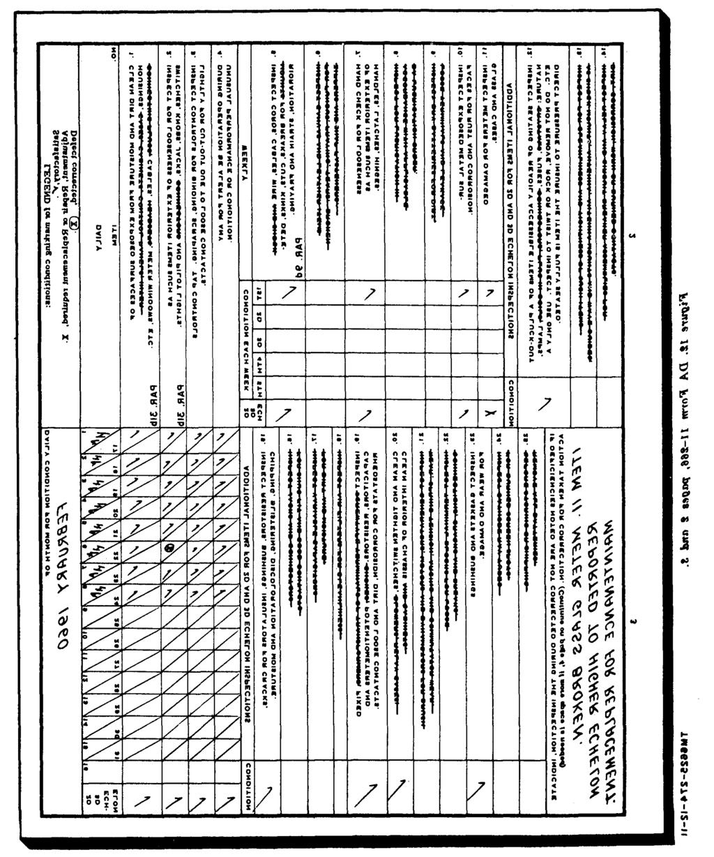
42 TM Figure
43 34. Visual Inspection a. When the equipment fails to perform properly, check the items listed below. (1) Test leads, if used, poorly connected or improperly connected. (2) (3) Incorrect pushbutton depressed. Improper setting of selector switches or controls (par. 18b (3)). (4) Battery or resistors improperly connected (par. 24a). (5) FUSE lamp defective. (6) LINE ADJUST control improperly b. If adjusted (par. 17c). the above checks do not locate the trouble, proceed to the equipment performance checklist (par. 35). 35. Equipment Performance Checklist a. General. The equipment performance checklist provides a procedure for systematically checking equipment performance. All corrective measures that the operator or the organizational maintenance man can perform are given in the Corrective measures column. When using the checklist, start at step 1 and follow each step in order. If the corrective measures indicated do not repair the equipment, troubleshooting is required by higher echelon. Note on the repair tag how the equipment performed and the corrective measures that were taken. Perform the steps in b below. b. Checklist. Shp I f.m Adion or csmditiem Corredi.* meosurm P R E P A R A T o R Y 1 Ac line cord. 2 POWER switch. 3 Meter. 4 Pushbutton l LINE ADJ. 5 LINE ADJUST control knob. 6 Selectors. 7 FUNCTION SWITCH. 8 POWER switch. Connect ac line cord to power source. Set switch to ON position. Depress pushbutton. Rotate control knob, while holding pushbutton l LINE ADJ. down, until meter pointer is directly over LINE TEST mark. Set selectors as directed in paragraph 17e ( 1). Rotate switch through the five SHORTS positions. Set switch to OFF position. PILOT lamp lights. Pointer stays at zero. Meter pointer moves up-scale. Meter pointer moves when control knob is turned. Selector knobs should be tight and point directly at a number or letter. The switch detents should be positive. SHORTS lamp glows at positions 2 and 3 of switch. PILOT lamp goes out. Check ac line cord connection. Remove (par. 39a ) and check ( par. 23) PILOT lamp; replace if defective. Remove (par. 39fl) and check (par. 23) FUSE lamp; replace if defective. Higher echelon repair required. Defective type 86 tube; replace tube (par. 37). Higher echelon repair required. Check for low-line voltage if pointer will not adjust properly. Higher echelon repair required. When a selector pointer is between two numbers or two letters, rotate switch fully counterclockwise. Loosen knob setscrew, turn knob until it points directly at the first number or Ietter, and tighten setscrew. Tighten I,oose knobs. If switch detents are not positive, higher echelon repair is required. Check switch settings. Replace SHORTS lamp (par. 39 b). Higher echelon repair required. 25
44 * Itm dab w CdhIa s 9 Seleetore and Set according to test being T controls. performed. ; 10 Tube under teat. Insert in proper test socket. Make connections 8s required. T In I POWER switch.! Set stitch ti ON position. E Q u I P M E N T P E R F o R M AN c E s Meter. BIAS control Panel lamp test socket. Adapter E104 (fig. 8). Adapter E106 (fig. 8). 17 Adapter E107 (fig. 8). Checking tube for dynamic mutual conductance, emission, or gas. Gas test. Checking a panel (pilot) lamp (par. 23). Testing long lead subminiature tube. Testing tube type 3E29, 829-B, or 832-A. Testing tube type 2C89. Tube pins enter test socket without forcing. PILOT lamp lights. Check for bent pins. Straighten pins of miniature tubes in one of the pin straighteners. Meter pointer indi- If meter pointer stays at zero, catas condition of tube under test may be detube under test fective. when proper push- Check setting of selectors and button is depressed. controls. Test another tube. Higher echelon repair required. Adjust BIAS control knob un- til pointer indicates 100, then proceed with gas test. Meter pointer can be adjusted to 10 by turning control knob. A good lamp will light. Meter indicates condition of tube when proper pushbutton is depressed. Meter indicates condition of tube when pushbutton 3 MUT. COND. is depressed. Make good contact between lamp and test socket. Check c~ntrol settings. Lamp may be defective; check other lamps if available. Higher echelon repair required. Unsnap locking device on adapter, move tube up and down to check seating of leads, and secure locking device. Test tube again. Check control settings. Check ~otatio~ column in test data book for type basing used. Compare placement of tube leads to basing diagram (fig. 10). Replace adapter and check tube again. If meter pointer does not move when correct pushbutton is depressed, test another tube. Higher echelon repair required. Check seating of adapter and tube. Check plate lead for a good connection. Check setting of controls. Test another tube. If meter pointer does not move, replace adapter. Higher echelon repair required. Check seating of tube and Meter indicates condition of tube when adapter. Remove adapter pushbutton 3 MUT. COND. is depressed, and tube and squeeze spring contacts closer together if necessary. Check setting of controls. Replace adapter and tube in test socket and test tube again. 26
45 Shl Adu w Cditlu NwR91 indication COrmtivc MOOlurw E Q u I P M E N T P E R F o R M A N c E Socket X109 (fig. 9). Socket X11O (fig. 9). Testing flat subminiature tube. Testing round subminiature tube. Meter indicates condition of tube when proper pushbutton is depressed. Meter indicates condition of tube when proper pushbutton is depressed. Test another tube. If meter pointer does not move, replace adapter. Higher echelon repair required. Check to see that dot on base of tube is aligned with dot on test socket. Slide tube leads up and down in test socket to insure good contact. Check setting of controls. Test another tube. Higher echelon repair required. Slide tube leads up and down in test socket to insure good contact. Check setting of controls. Check Notations column in test data book for type basing used. Compare placement of tube leads to basing diagram (fig. 10). Test another tube. Higher echelon repair required. s T!0!1 ube under tesk OWER switch, Remove from test socket. Set to OFF position. PILOT lamp goes out. o 82 ic line cord. Remove ac line cord plug P from power source. 36. Removal of Chassis a. Removal. (1) (2) (3) (4) (5) Unsnap the latches and open the cover of the test set. Unwind the ac line cord from the retainer bracket and remove the cover from the test set. Remove the cover by sliding it to one side until the hinge pins are disengaged. Remove the screws that secure the front panel to the case. Hold the front panel to the case, turn the test set over, and gently place it on a clean, flat surface. Slowly lift the test set case upward until it is clear of the chassis. b. Replacement. (1) Position the test set case so that the handle is forward. (2) Carefully lower the test set into the case. Be sure that no wires are caught between the front panel and the edge of the case. (3) Replace the screws that secure the front panel to the case. Tighten the screws in rotation a little at a time to prevent binding. (4) Replace the cover on the case, wind the ac line cord counterclockwise on the retainer bracket, secure the plug under the clip (not on TV-7/U), close the cover, and secure the latches. 37. Tube Replacement When trouble occurs, check the ac line cord connection and the control settinge before removing any tubes. If tube failure is suspected, use the tube substitution method (a below) to check the tubes. 27

46 Caution: Do not rock or rotate a tube when removing it from a socket; pull it straight out with a tube puller. a. Tube Substitution Method. Replace a suspected tube (b below) with a new tube. If the equipment still does not work, remove the new tube and put back the original tube. Repeat this procedure with the other tube. If the test set is still inoperative, other checks are required (par. 35b). b. Replacing Tubes in Test Set, Electron Tube TV-7(*)/U. Check the tubes in the test set as follows: (1) Remove the chassis from the case (par. 36a). (2) Remove the tube clamp (fig. 13) from the threaded stud and remove the tube. Caution: Be careful not to hit the meter case with tube type 83 when removing the tube. (3) Replace the tube (a above) with one of the running spares. (4) Set the tube (or a replacement) in the socket and secure it with the tube clamp. (5) Replace the chassis in the case (par. 36b). 38. Preferred-Type Tubes A preferred-type electron tube, type 5Y3WGTA, has been developed as a direct replacement for nonpreferred types 5Y3GT and 5Y3WGT (par. 7). The 5Y3WGTA is used in the power supply. When replacement of a 5Y3GT or a 5Y3WGT is necessary, replace it with a 5Y3WGTA. Do not substitute a 5Y3GT or a 5Y3WGT for a 5Y3WGTA. TM Figure 13. Tube location. 39. Replacement of Lamps bayonet-type bases. Unscrew and remove the The FUSE, PILOT, and SHORTS lamps are PILOT lamp indicator jewel to gain access to the PILOT lamp. To remove either lamp, press removable from the front panel of the test set. downward, turn the lamp to the left, and lift a. The FUSE lamp and PILOT lamp have straight up. To replace the FUSE or PILOT 28
47 lamp, insert the lamp in the appropriate socket, press downward, turn the lamp to the right, and release it. Replace the PILOT lamp indicater jewel. b. The SHORTS lamp has a screw-type base. Remove the lamp by turning it to the left; replace the lamp by turning it to the right. 29
48 CHAPTER 4 SHIPMENT, LIMITED STORAGE, AND DEMOLITION TO PREVENT ENEMY USE Section I SHIPMENT AND LIMITED STORAGE 40. Removal From Service a. Set the POWER switch to the OFF position and disconnect the test set from the power source. b. Place the adapters under the clamps on the cover. c. Wind the ac line cord counterclockwise around the retainer bracket and place the plug under the clip (not on TV-7/U). Place the test leads under the coiled ac line cord (TV-7/U and TV-7A/U) or as shown in figures 1 and 2. On the TV-7B/U and the TV-7D/U, insert one end of the test leads into the storage clips and connect the alligator clips to the studs (fig. 3 and 4). d. Close the cover and secure it with the latches. 41. Repackaging for Shipment or Limited Storage (fig. 14) The exact procedure for repackaging depends on the material available and the conditions under which the equipment is to be shipped or stored. Adapt the procedures outlined below whenever circumstances permit. The information concerning the original packaging (par. 8) will also be helpful. a. Material Requirements. The following materials are required for repackaging Test Set, Electron Tube TV-7(*)/U. For stock numbers of materials, consult SB Flexible corrugated fiberboard Waterproof wrapping paper Gummed paper tape Pressure-sensitive tape Metal strapping (%- by inch).. (Nok Strapping seal. required) Wooden box (inside dimensions: 189$ by 10?4-by 7%-inch) b. Packaging. (1) (2) (3) c. Packing. (1) (2) (3) (4) (5) 10 Sq ft 10 Sq ft 3 ft 4 ft 8 ft 1 ea (9 bd ft) Technical manual. Package the technical manuals within a close-fitting bag fabricated of waterproof wrapping paper. Seal the seams with pressure-sensitive tape. Spare parts. Wrap each part within a layer of flexible corrugated fiberboard. Seal the seams with gummed paper tape. Overwrap the flexible corrugated fiberboard with waterproof wrapping paper and seal with pressure-sensitive tape. Test set. The procedure used to package the test set is the same as the procedure used to package the spare parts ((2) above). Fabricate a wooden box. Place the packaged test set (b(3) above) in the wooden box. Place the spare parts (b(2) above) and the technical manuals on top of the test set. Nail down the wooden cover. Strap the wooden box when intertheater shipment is involved. 30
49 TM Figure 14. Field repackaging diagram. 31
50 Section Il. DEMOLITION OF MATERIEL TO PREVENT ENEMY USE 42. Authority for Demolition The destruction procedures outlined in paragraph 43 will be used to prevent further use of the equipment. Demolition of the equipment will be accomplished only upon the order of the commander. 43. Methods of Destruction Any or all of the methods of destruction given below may be used. a. Smash. Use sledges, axes, hammers, crowbars, or any other heavy tools available; smash the case, cover, adapters, front panel, and meter. b. Cut. Use axes, handaxes, machetes, or knives; cut the ac line cord and test leads. c. Burn. Use gasoline, kerosene, oil, flamethrowers, or incendiary grenades; bum the technical manuals and test data book. Warning: Be extremely careful with explosive and incendiary devices. Use these items only when the need is urgent. d. Explode. Use grenades, TNT, or firearms, if explosives are necessary. e. Dispose. Bury or scatter destroyed parts or throw them into nearby waterways. 32
51 APPENDIX I REFERENCES Following is a list of applicable references available to the operator or organizational maintenance personnel of Test Set, Electron Tube TV-7(*)/U: SB Preservation, Packaging and Packing Materials, Supplies and Equipment Used by the Army TB Tube Test Data for Electron Tube Test Sets TV-7/U, TV- 7A/U, TV-7B/U, and TV-7D/U TM P Organizational Maintenance Repair Parts and Special Tools List and Maintenance Allocation Chart for Test Sets, Electron Tube TV- 7/U, TV-7A/U, TV-7B/U and TV- 7D/U 33
52 APPENDIX II OPERATOR S MAINTENANCE REPAIR PARTS AND SPECIAL TOOLS LIST Section I INTRODUCTION 1. Scope a. General. This appendix lists items supplied for initial operation and for running spares. The list includes tools, accessories, parts, and material issued as part of the major item, and all items authorized for basic operator maintenance of the equipment. End items of equipment are issued on the basis of allowances prescribed in equipment authorization tables and other documents that are a basis for requisitioning. b. Columns. The columns are as follows: (1) Source, maintenance, and recoverability code. Not used. (2) Federal stock number. This column lists the 11-digit Federal stock number. (3) Designation by model. A dagger indicates the model in which the part is used. (4) Description. Nomenclature or the standard item name and brief identifying data for each item are listed in this column. When requisitioning, enter the nomenclature and description on the requisition. (5) Unit of issue. The unit of issue is the supply term by which the individual item is counted for procurement, (6) (7) (8) (9) storage, requisitioning, allowances, and issue purposes. Expendability. Expendable items are indicated by X; nonexpendable items are indicated by NX. Quantity authorized. Under Items Comprising an Operable Equipment, the column lists the quantity of items supplied for the initial operation of the equipment. Under Running Spares and Accessory Items the quantities are those issued initially with the equipment as spare parts. The quantities are authorized to be kept on hand by the operator for maintenance of the equipment. Illustratrations (Figure No.). The numbers in this column refer to the illustration or illustrations where the part is shown. Illustrations (Item No.). This column lists the reference symbols used for identification of items in the illustrations or text of the manual. 2. Critical Items A zero slash (0) in the Description column indicates items that are expected to fail during the first year; also items that will make the equipment inoperative if they fail. 34

53 TM Section II 35
54 TM Figure 15. Electron tubes and lamps. 36
55 APPENDIX III MAINTENANCE ALLOCATION CHART Section I INTRODUCTION 1. Scope a. General. This appendix assigns maintenance functions and repair operations to be performed by the lowest appropriate maintenance echelon. b. Allocation of Maintenance Functions. Columns in section II, Allocation of Maintenance Functions, are defined as follows: (1) (2) (a) (b) (c) (d) (e) (f) Part or component. This column shows only the nomenclature or standard item. Additional descriptive data are included only where clarification is necessary to identify the part. Components and parts comprising a major end item are listed alphabetically. Assemblies and subassemblies are in alphabetical sequence with their components listed alphabetically immediately below the assembly listing. Maintenance function. This column indicates the various maintenance functions allocated to the echelon capable of performing the operations. Service. To clean, to preserve, and to replenish fuel and lubricants. Adjust. To regulate periodically to prevent malfunction. Inspect. To verify serviceability and to detect incipient electrical or mechanical failure by scrutiny. Test. To verify serviceability and to detect incipient electrical or mechanical failure by use of special equipment such as gages, meters, etc. Replace. To substitute serviceable assemblies, subassemblies, and parts for unserviceable components. Repair. To restore to a serviceable condition by replacing unserviceable parts or by any other action required utilizing tools, equipment, and skills available, to include welding, grinding, riveting, straightening, adjusting, etc. (3) (4) (5) (g) Calibrate. To determine, check, or rectify the graduation of an instrument, weapon, or weapons system, or components of a weapons system. (h) Rebuild. To restore to a condition comparable to new by disassembling the item to determine the condition of its component parts and reassembling it using serviceable, rebuilt, or new assemblies, subassemblies, and parts. 1st, 2d, 3d, 4th, 5th echelon. The symbol X indicates the echelon responsible for performing that particular maintenance operation, but does not necessarily indicate that repair parts will be stocked at that level. Echelons higher than the echelon marked by X are authorized to perform the indicated operation. Column 5 is not used. Tools required. This column indicates the tool, test, and maintenance equipments required to perform the maintenance functions. These numbers are identified in section III, Allocation of Tools for Maintenance Functions. Remarks. This column contains any notations necessary to clarify the data cited in the preceding columns. c. Allocation of Tools for Maintenance Functions. Columns in section III, Allocation of Tools for Maintenance Functions, are as follows: (1) Tools required for maintenance functions. This column lists the tools and test equipment required to perform the maintenance functions. (2) 1st, 2nd, 3rd, 4th, and 5th echelon. A dagger in columns 3, 5, and 6 indicates that the tool or test equipment is allocated to that echelon. Columns 2 and 4 are not used. (3) Tool code. This column lists the tool code assigned. The numbers are used 37
56 in the maintenance allocation chart to refer to the indicated item. (4) Remarks. Not used. 2. Maintenance by Using Organizations When this equipment is used by signal service organizations organic to theater headquarters or communication zones to provide theater communications, those maintenance functions allocated up to and including fourth echelon are authorized to the organization operating this equipment. 3. Mounting Hardware The basic entries of the maintenance allocation chart do not include mounting hardware such as screws, nuts, bolts, washers, brackets, and clamps. 38
57 Section II 39
58 40
59 41
60 By Order of Wilber M. Brucker, Secretary of the Army: Official: R. V. LEE, Major General, United States Army, The Adjutant General. L. L. LEMNITZER General, United States Army, Chief of Staff. Distribution: 42 Active Army: To be distributed in accordance with DA Form 12-7 requirements for TM 11 Series plus the following additional formula: USASA (1) CNGB (1) Def Atomic Spt Agcy (6) Tech Sti, DA (1) except CSigO (18) USA Abn & Elct Bd (1) USA ATB (1) US ARADCOM (2) (AA-AD) US ARADCOM Rgn (2) MDW (1) Seventh, US Army (5) EUSA (6) Corps (2) 6-1oo USASCS (26) JBUSMC (2) Units org under the fol TOE: (2 copies each) s S
61 (AA-AH) (AA-AC) 1* * S S s (AA-AE) (AA-AE)
62 (AA-AC) (AAj AB) (AA-AC) U M H H16 u M-m (AA-AE) NC/ Stati AG (8); tl~ame M Active Army except l llowance ie one copy te eaeh unk USARt None For explanation of l bbrevixtione uee& eee AR H. 44
63
64 THE METRIC SYSTEM AND EQUIVALENTS
65 PIN:

66 This fine document... Was brought to you by me: Liberated Manuals -- free army and government manuals Why do I do it? I am tired of sleazy CD-ROM sellers, who take publicly available information, slap watermarks and other junk on it, and sell it. Those masters of search engine manipulation make sure that their sites that sell free information, come up first in search engines. They did not create it... They did not even scan it... Why should they get your money? Why are not letting you give those free manuals to your friends? I am setting this document FREE. This document was made by the US Government and is NOT protected by Copyright. Feel free to share, republish, sell and so on. I am not asking you for donations, fees or handouts. If you can, please provide a link to liberatedmanuals.com, so that free manuals come up first in search engines: <A HREF= Military and Government Manuals</A> Sincerely Igor Chudov Chicago Machinery Movers
TECHNICAL MANUAL OPERATOR S ORGANIZATIONAL SIRECT SUPPORT AND GENERAL SUPPORT MAINTENANCE MANUAL METER TEST SETS TS-682/GSM-1 AND TS-682A/GSM-1
 TECHNICAL MANUAL OPERATOR S ORGANIZATIONAL SIRECT SUPPORT AND GENERAL SUPPORT MAINTENANCE MANUAL METER TEST SETS TS-682/GSM-1 AND TS-682A/GSM-1 (NSN 6625-00-669-0747) This copy is a reprint which includes
TM &P TECHNICAL MANUAL
 TECHNICAL MANUAL TM 9-2330-376-14&P OPERATOR S, ORGANIZATIONAL, DIRECT SUPPORT AND GENERAL SUPPORT MAINTENANCE MANUAL (INCLUDING REPAIR PARTS AND SPECIAL TOOLS LISTS) FOR CHASSIS, TRAILER: 5-TON, 4-WHEEL,
TM milradio_install Return to the Online Manuals Mainpage
 Return to the Online Manuals Mainpage TM 11-2300-373-14-5 INSTRUCTIONS FOR INSTALLING INSTALLATION KIT, ELECTRONIC EQUIPM MK-1239/VRC-12 IN TRUCK, CARGO, 1 1/4-TON, M715 (RADIO SET, AN/VRC-12). Index:
TECHNICAL MANUAL M149A2. This manual supersedes TM &P, dated February 1981, and all changes.
 TECHNICAL MANUAL TM 9-2330-267-14&P OPERATOR S, ORGANIZATIONAL, DIRECT SUPPORT, AND GENERAL SUPPORT MAINTENANCE MANUAL (INCLUDING REPAIR PARTS AND SPECIAL TOOLS LISTS) FOR TRAILER, TANK, WATER: 400 GALLON,
TM TECHNICAL MANUAL UNIT, INTERMEDIATE DIRECT SUPPORT AND INTERMEDIATE GENERAL SUPPORT MAINTENANCE INSTRUCTIONS
 TECHNICAL MANUAL UNIT, INTERMEDIATE DIRECT SUPPORT AND INTERMEDIATE GENERAL SUPPORT MAINTENANCE INSTRUCTIONS MAIN REDUCTION GEAR FOR LANDING CRAFT UTILITY (LCU) NSN 1905-01-154-1191 INTRODUCTION 1-1 UNIT
1 1/2-TON, 2-WHEEL, M332 PAGE B1 (NSN ) REPAIR PARTS AND SPECIAL TOOLS LIST PAGE F-1
 REPAIR PARTS AND SPECIAL TOOLS LIST PAGE F-1") TECHNICAL MANUAL OPERATOR'S, ORGANIZATIONAL, DIRECT SUPPORT, AND GENERAL SUPPORT MAINTENANCE (INCLUDING REPAIR PARTS AND SPECIAL TOOLS LIST) OPERATING INSTRUCTIONS PAGE 2-1 OPERATOR PMCS PAGE 2-4 OPERATOR
TECHNICAL MANUAL OPERATOR'S, ORGANIZATIONAL, DIRECT SUPPORT, AND GENERAL SUPPORT MAINTENANCE (INCLUDING REPAIR PARTS AND SPECIAL TOOLS LIST) OPERATING INSTRUCTIONS PAGE 2-1 OPERATOR PMCS PAGE 2-4 OPERATOR
TECHNICAL MANUAL CHASSIS, TRAILER: GENERAL PURPOSE, 3-1/2 TON, 2-WHEEL, M353 (NSN )
") TECHNICAL MANUAL OPERATOR S, ORGANIZATIONAL, DIRECT SUPPORT, AND GENERAL SUPPORT MAINTENANCE MANUAL (INCLUDING REPAIR PARTS AND SPECIAL TOOLS LISTS) FOR CHASSIS, TRAILER: GENERAL PURPOSE, 3-1/2 TON, 2-WHEEL,
TECHNICAL MANUAL OPERATOR S, ORGANIZATIONAL, DIRECT SUPPORT, AND GENERAL SUPPORT MAINTENANCE MANUAL (INCLUDING REPAIR PARTS AND SPECIAL TOOLS LISTS) FOR CHASSIS, TRAILER: GENERAL PURPOSE, 3-1/2 TON, 2-WHEEL,
TM &P TECHNICAL MANUAL
 TECHNICAL MANUAL OPERATOR S, ORGANIZATIONAL, DIRECT SUPPORT, AND GENERAL SUPPORT MAINTENANCE MANUAL (INCLUDING REPAIR PARTS AND SPECIAL TOOLS LISTS) FOR TM 9-2330-359-14&P SEMITRAILER, FLATBED: BREAKBULK/CONTAINER
DEPARTMENT OF THE ARMY TECHNICAL MANUAL
 DEPARTMENT OF THE ARMY TECHNICAL MANUAL OPERATOR, ORGANIZATIONAL, FIELD AND DEPOT MAINTENANCE MANUAL WELDING MACHINE, ARC GENERATOR; ELEC MOTOR DRIVEN; AC 220V, 3-PHASE, 60 CYCLE, SINGLE OPERATOR; REMOTE
TECHNICAL MANUAL ORGANIZATIONAL MAINTENANCE MANUAL VOLUME 1 OF 3
 TECHNICAL MANUAL ORGANIZATIONAL MAINTENANCE MANUAL VOLUME 1 OF 3 This copy is a reprint which includes current pages from Change 1. TRACTOR, WHEELED (DED) LOADER BACKHOE W/HYDRAULIC IMPACT TOOL AND WIHYDRAULIC
THIS MANUAL SUPERSEDES TM DATED 30 MAY 1994, INCLUDING ALL CHANGES. TECHNICAL MANUAL
 THIS MANUAL SUPERSEDES TM 9-2330-385-14 DATED 30 MAY 1994, INCLUDING ALL CHANGES. TECHNICAL MANUAL OPERATOR S, UNIT, DIRECT SUPPORT AND GENERAL SUPPORT MAINTENANCE MANUAL INTRODUCTION 1-1 OPERATING INSTRUCTIONS
TECHNICAL MANUAL OPERATOR'S, UNIT, DIRECT SUPPORT, AND GENERAL SUPPORT MAINTENANCE MANUAL (INCLUDING REPAIR PARTS AND SPECIAL TOOLS LISTS) FOR
 FOR") TECHNICAL MANUAL OPERATOR'S, UNIT, DIRECT SUPPORT, AND GENERAL SUPPORT MAINTENANCE MANUAL (INCLUDING REPAIR PARTS AND SPECIAL TOOLS LISTS) Operating Instructions 2-1 FOR DISTRIBUTOR, WATER, SEMITRAILER
TECHNICAL MANUAL OPERATOR'S, UNIT, DIRECT SUPPORT, AND GENERAL SUPPORT MAINTENANCE MANUAL (INCLUDING REPAIR PARTS AND SPECIAL TOOLS LISTS) Operating Instructions 2-1 FOR DISTRIBUTOR, WATER, SEMITRAILER
TECHNICAL MANUAL OPERATOR'S, ORGANIZATIONAL, DIRECT SUPPORT AND GENERAL SUPPORT MAINTENANCE MANUAL
 TECHNICAL MANUAL OPERATOR'S, ORGANIZATIONAL, DIRECT SUPPORT AND GENERAL SUPPORT MAINTENANCE MANUAL COMPRESSOR, ROTARY; AIR, SKID MOUNTED; DIESEL ENGINE DRIVEN, 125 CFM, 100 PSIG (DAVEY MODEL 6M125) NSN
OPERATOR'S MANUAL COMPONENT OF CRUSHING AND SCREENING PLANT: DIESEL AND ELECTRIC DRIVEN, WHEEL MOUNTED, 75 TON PER HOUR
 OPERATOR'S MANUAL FOR CRUSHER, ROLL: DIESEL AND ELECTRIC DRIVEN, WHEEL MOUNTED, PNEUMATIC TIRES, 75 TON PER HOUR EAGLE CRUSHER MODEL 5230B AND 5230C (NSN 3820-00-788-5999) EAGLE CRUSHER MODEL 5230D (NSN
BULLDOZER, EARTH MOVING: TANK MOUNTING, M9 ( )
") TECHNICAL MANUAL OPERATOR, ORGANIZATIONAL, DIRECT SUPPORT, AND GENERAL SUPPORT MAINTENANCE MANUAL (INCLUDING REPAIR PARTS AND SPECIAL TOOLS LIST) FOR BULLDOZER, EARTH MOVING: TANK MOUNTING, M9 (2590-00-708-3563)
TECHNICAL MANUAL OPERATOR, ORGANIZATIONAL, DIRECT SUPPORT, AND GENERAL SUPPORT MAINTENANCE MANUAL (INCLUDING REPAIR PARTS AND SPECIAL TOOLS LIST) FOR BULLDOZER, EARTH MOVING: TANK MOUNTING, M9 (2590-00-708-3563)
TECHNICAL MANUAL ORGANIZATIONAL, DIRECT SUPPORT, AND GENERAL SUPPORT MAINTENANCE MANUAL WITH REPAIR PARTS AND SPECIAL TOOLS LIST
 TECHNICAL MANUAL ORGANIZATIONAL, DIRECT SUPPORT, AND GENERAL SUPPORT MAINTENANCE MANUAL WITH REPAIR PARTS AND SPECIAL TOOLS LIST BITUMINOUS DISTRIBUTOR BODY M918, MODEL D-63 NSN 3895-01-028-4390 E.D. ETNYRE
TECHNICAL MANUAL OPERATOR, AVIATION UNIT, AND AVIATION INTERMEDIATE MAINTENANCE MANUAL WITH REPAIR PARTS AND SPECIAL TOOLS LIST CHAPTER 1 INTRODUCTION
 EXTENDED RANGE FUEL SYSTEM ARMY MODEL CH-47 HELICOPTER TECHNICAL MANUAL OPERATOR, AVIATION UNIT, AND AVIATION INTERMEDIATE MAINTENANCE MANUAL WITH REPAIR PARTS AND SPECIAL TOOLS LIST CHAPTER 1 INTRODUCTION
US ARMY TM US MARINE CORPS TM 08580B-1 0/1 TECHNICAL MANUAL OPERATOR S MANUAL TABLE OF CONTENTS
 US ARMY TM 10-4610-239-10 US MARINE CORPS TM 08580B-1 0/1 TECHNICAL MANUAL OPERATOR S MANUAL WATER PURIFICATION UNIT, REVERSE OSMOSIS, 600 GPH TRAILER MOUNTED FLATBED CARGO, 5 TON 4 WHEEL TANDEM MODEL
DEPARTMENT OF THE ARMY TECHNICAL MANUAL OPERATOR S, UNIT, INTERMEDIATE DIRECT SUPPORT AND INTERMEDIATE GENERAL SUPPORT MAINTENANCE
 TM 9-2330-380-14 & P DEPARTMENT OF THE ARMY TECHNICAL MANUAL OPERATOR S, UNIT, INTERMEDIATE DIRECT SUPPORT AND INTERMEDIATE GENERAL SUPPORT MAINTENANCE (INCLUDING REPAIR PARTS AND SPECIAL TOOLS LISTS)
LUBRICATION ORDER LO JAN 84 (Supersedes LO , 25 FEBRUARY 1982)
") LUBRICATION ORDER LO 10 3930 632 12 10 JAN 84 (Supersedes, 25 FEBRUARY 1982) TRUCK, LIFT, FORK; GASOLINE ENGINE DRIVEN, SOLID RUBBER TIRED, 127-INCH LIFT; 2, 000 LB CAPACITY (CLARK EQUIPMEN-T MODEL 2329397,
LUBRICATION ORDER LO 10 3930 632 12 10 JAN 84 (Supersedes, 25 FEBRUARY 1982) TRUCK, LIFT, FORK; GASOLINE ENGINE DRIVEN, SOLID RUBBER TIRED, 127-INCH LIFT; 2, 000 LB CAPACITY (CLARK EQUIPMEN-T MODEL 2329397,
MAINTENANCE KIT, ELECTRONIC
 TM 11-6625-1635-35 DEPARTMENT OF THE ARMY TECHNICAL MANUAL DS, GS, AND DEPOT MAINTENANCE MANUAL INCLUDING REPAIR PARTS AND SPECIAL TOOLS LIST MAINTENANCE KIT, ELECTRONIC EQUIPMENT MK-1004/ARC I This copy
OPERATOR'S MANUAL CARRIER, CARGO, TRACKED, 1 /2 TON, M973 SMALL UNIT SUPPORT VEHICLE (SUSV) (NSN )
 (NSN )") OPERATOR'S MANUAL TABLE OF CONTENTS PAGE i EQUIPMENT DESCRIPTION PAGE 1-1 OPERATING INSTRUCTIONS PAGE 2-1 PREVENTIVE MAINTENANCE PAGE 2-6 CARRIER, CARGO, TRACKED, 1 /2 TON, M973 SMALL UNIT SUPPORT VEHICLE
OPERATOR'S MANUAL TABLE OF CONTENTS PAGE i EQUIPMENT DESCRIPTION PAGE 1-1 OPERATING INSTRUCTIONS PAGE 2-1 PREVENTIVE MAINTENANCE PAGE 2-6 CARRIER, CARGO, TRACKED, 1 /2 TON, M973 SMALL UNIT SUPPORT VEHICLE
LUBRICATION ORDER LO JULY 1990 (Supersedes LO , July 1985)
") LUBRICATION ORDER LO 9-2350-261-12 10 JULY 1990 (Supersedes LO 9-2350-261-12, July 1985) CARRIER, PERSONNEL, FULL TRACKED, ARMORED, M113A2: 2350-01-068-4077 CARRIER, COMMAND POST, LIGHT, TRACKED, M577A2:
LUBRICATION ORDER LO 9-2350-261-12 10 JULY 1990 (Supersedes LO 9-2350-261-12, July 1985) CARRIER, PERSONNEL, FULL TRACKED, ARMORED, M113A2: 2350-01-068-4077 CARRIER, COMMAND POST, LIGHT, TRACKED, M577A2:
HEADQUARTERS, DEPARTMENT OF THE ARMY
 TECHNICAL MANUAL OPERATOR'S, UNIT AND DIRECT SUPPORT MAINTENANCE MANUAL INCLUDING REPAIR PARTS AND SPECIAL TOOLS LIST EQUIPMENT DESCRIPTION 1-3 PRINCIPLES OF OPERATION 1-6 DESCRIPTION AND USE OF OPERATOR'S
POWER SUPPLY PP-6148/U (NSN
 TECHNICAL MANUAL TM 11-6130-356-12 OPERATOR S AND ORGANIZATIONAL MAINTENANCE MANUAL POWER SUPPLY PP-6148/U (NSN 6130-01-062-3618) This copy is a reprint which includes current pages from Change 1. HEADQUARTERS,
TECHNICAL MANUAL OPERATOR S, UNIT, DIRECT SUPPORT, AND GENERAL SUPPORT MAINTENANCE MANUAL FOR
 TECHNICAL MANUAL OPERATOR S, UNIT, DIRECT SUPPORT, AND GENERAL SUPPORT MAINTENANCE MANUAL FOR SEMITRAILER, TANK: 5000 GALLON, (POTABLE WATER DISPENSING) XM1098 (NSN 2330-01-330-2779) Approved for public
TECHNICAL MANUAL OPERATOR S, ORGANIZATIONAL AND DIRECT SUPPORT MAINTENANCE MANUAL TANK AND PUMP UNIT, LIQUID DISPENSING
 TECHNICAL MANUAL OPERATOR S, ORGANIZATIONAL AND DIRECT SUPPORT MAINTENANCE MANUAL TANK AND PUMP UNIT, LIQUID DISPENSING FOR TRUCK MOUNTING (UNITED MANUFACTURING AND ENGINEERING CORP. MODEL STYLE 1) NSN
TECHNICAL MANUAL UNIT, DIRECT SUPPORT AND GENERAL SUPPORT MAINTENANCE INSTRUCTIONS
 TECHNICAL MANUAL UNIT, DIRECT SUPPORT AND GENERAL SUPPORT MAINTENANCE INSTRUCTIONS DIESEL ENGINE MODEL 4039T 4 CYLINDER 3.9 LITER NSN: 2815-01-350-2208 This copy is a reprint which includes current pages
TECHNICAL MANUAL OPERATOR S, ORGANIZATIONAL, DIRECT SUPPORT AND GENERAL SUPPORT MAINTENANCE MANUAL (INCLUDING REPAIR PARTS AND SPECIAL TOOLS LIST)
") TECHNICAL MANUAL OPERATOR S, ORGANIZATIONAL, DIRECT SUPPORT AND GENERAL SUPPORT MAINTENANCE MANUAL (INCLUDING REPAIR PARTS AND SPECIAL TOOLS LIST) SEMITRAILER, VAN: ELECTRONIC 10-TON, 4 WHEEL XM574 (2330-00-086-7406)
TECHNICAL MANUAL OPERATOR S, ORGANIZATIONAL, DIRECT SUPPORT AND GENERAL SUPPORT MAINTENANCE MANUAL (INCLUDING REPAIR PARTS AND SPECIAL TOOLS LIST) SEMITRAILER, VAN: ELECTRONIC 10-TON, 4 WHEEL XM574 (2330-00-086-7406)
DEPARTMENT OF THE ARMY TECHNICAL MANUAL OPERATOR AND ORGANIZATIONAL MAINTENANCE MANUAL (INCLUDING REPAIR PARTS AND SPECIAL TOOLS LIST) FOR
 FOR") TM 9-4910-389-12 DEPARTMENT OF THE ARMY TECHNICAL MANUAL OPERATOR AND ORGANIZATIONAL MAINTENANCE MANUAL (INCLUDING REPAIR PARTS AND SPECIAL TOOLS LIST) FOR CLEANER AND TESTER, SPARK PLUG: BENCH MOUNTED
TM 9-4910-389-12 DEPARTMENT OF THE ARMY TECHNICAL MANUAL OPERATOR AND ORGANIZATIONAL MAINTENANCE MANUAL (INCLUDING REPAIR PARTS AND SPECIAL TOOLS LIST) FOR CLEANER AND TESTER, SPARK PLUG: BENCH MOUNTED
TM OPERATOR S MANUAL HEADQUARTERS, DEPARTMENT OF THE ARMY 1 SEPT 87
 OPERATOR S MANUAL LOADER, SCOOP TYPE, DED 4x4, ARTICULATED FRAME STEER, 2-1/2 CUBIC YARD (J.I.CASE MODEL MW24C) (NSN 3805-01-150-4814) HEADQUARTERS, DEPARTMENT OF THE ARMY 1 SEPT 87 d MW24C Loader Technical
ARMY TM MARINE CORPS TM 09295A-14/1 TECHNICAL MANUAL
 ARMY TM 9-2330-381-14 MARINE CORPS TM 09295A-14/1 TECHNICAL MANUAL OPERATOR'S, UNIT, DIRECT SUPPORT, AND GENERAL SUPPORT MAINTENANCE MANUAL FOR HEAVY EQUIPMENT TRANSPORTER SEMITRAILER 70 TON, M1000 NSN
TM CHARGER, BATTERY PP-7286/U (NSN ) TECHNICAL MANUAL OPERATOR S AND ORGANIZATIONAL MAINTENANCE MANUAL FOR
 TECHNICAL MANUAL OPERATOR S AND ORGANIZATIONAL MAINTENANCE MANUAL FOR") TECHNICAL MANUAL OPERATOR S AND ORGANIZATIONAL MAINTENANCE MANUAL FOR CHARGER, BATTERY PP-7286/U (NSN 6130-01-041-3490) This copy is a reprint which includes current pages from Change 1. HEADQUARTERS,
TECHNICAL MANUAL OPERATOR S AND ORGANIZATIONAL MAINTENANCE MANUAL FOR CHARGER, BATTERY PP-7286/U (NSN 6130-01-041-3490) This copy is a reprint which includes current pages from Change 1. HEADQUARTERS,
TECHNICAL MANUAL OPERATOR, ORGANIZATIONAL, DIRECT AND GENERAL SUPPORT MAINTENANCE MANUAL
 TM 5-4310-348-14 TECHNICAL MANUAL OPERATOR, ORGANIZATIONAL, DIRECT AND GENERAL SUPPORT MAINTENANCE MANUAL COMPRESSOR, AIR, RECIPROCATING, ELECTRIC MOTOR DRIVEN, RECEIVER MOUNTED, 2HP, 5CFM, 175 PSI, (INGERSOLL-RAND
ARMY TM &P AIR FORCE TO 36A
 ARMY TM 9-2330-213-14&P AIR FORCE TO 36A11-1-461 TECHNICAL MANUAL OPERATOR S, UNIT, DIRECT SUPPORT, AND GENERAL SUPPORT MAINTENANCE MANUAL (INCLUDING REPAIR PARTS AND SPECIAL TOOLS LISTS) FOR TRAILER,
UNIT MAINTENANCE INSTRUCTIONS PAGE 2-1 DIRECT SUPPORT
 TECHNICAL MANUAL TABLE OF CONTENTS PAGE i INTRODUCTION PAGE 1-1 UNIT, DIRECT SUPPORT AND GENERAL SUPPORT MAINTENANCE MANUAL UNIT MAINTENANCE INSTRUCTIONS PAGE 2-1 DIRECT SUPPORT MAINTENANCE INSTRUCTIONS
OPERATOR'S MANUAL FOR
 OPERATOR'S MANUAL FOR CRUSHER, JAW: DIESEL AND ELECTRIC DRIVEN, WHEEL MOUNTED, PNEUMATIC TIRES, 75 TON PER HOUR EAGLE CRUSHER MODEL 5157 AND 5157A (NSN 3820-00-783-7311) EAGLE CRUSHER MODEL 5157B (NSN
M48A5 TANK CHASSIS, TRANSPORTING: FOR BRIDGE, ARMORED-VEHICLE-LAUNCHED SCISSORING TYPE,CLASS 60 (NSN )
") TECHNICAL MANUAL ORGANIZATIONAL MAINTENANCE This copy is a reprint which includes current pages from Changes 1 through 3. M48A5 TANK CHASSIS, TRANSPORTING: FOR BRIDGE, ARMORED-VEHICLE-LAUNCHED SCISSORING
TECHNICAL MANUAL ORGANIZATIONAL MAINTENANCE This copy is a reprint which includes current pages from Changes 1 through 3. M48A5 TANK CHASSIS, TRANSPORTING: FOR BRIDGE, ARMORED-VEHICLE-LAUNCHED SCISSORING
TECHNICAL MANUAL OPERATOR'S, UNIT, DIRECT SUPPORT AND GENERAL SUPPORT MAINTENANCE MANUAL (INCLUDING REPAIR PARTS AND SPECIAL TOOLS LIST)
") TECHNICAL MANUAL OPERATOR'S, UNIT, DIRECT SUPPORT AND GENERAL SUPPORT MAINTENANCE MANUAL (INCLUDING REPAIR PARTS AND SPECIAL TOOLS LIST) INTRODUCTION 1-1 OPERATING INSTRUCTIONS 2-1 OPERATOR MAINTENANCE
TECHNICAL MANUAL OPERATOR'S, UNIT, DIRECT SUPPORT AND GENERAL SUPPORT MAINTENANCE MANUAL (INCLUDING REPAIR PARTS AND SPECIAL TOOLS LIST) INTRODUCTION 1-1 OPERATING INSTRUCTIONS 2-1 OPERATOR MAINTENANCE
TECHNICAL MANUAL. Operator's, Organizational and Direct Support Maintenance Manual (Including Repair Parts and Special Tools List) for
 for") TECHNICAL MANUAL Operator's, Organizational and Direct Support Maintenance Manual (Including Repair Parts and Special Tools List) for CONVERTER ASSEMBLY, VAPOR RECOVERY PART NUMBER F428A NSN 2590-01-090-7659
TECHNICAL MANUAL Operator's, Organizational and Direct Support Maintenance Manual (Including Repair Parts and Special Tools List) for CONVERTER ASSEMBLY, VAPOR RECOVERY PART NUMBER F428A NSN 2590-01-090-7659
TM THIS MANUAL SUPERSEDES TM DATED 25 FEB 1994, INCLUDING ALL CHANGES.
 THIS MANUAL SUPERSEDES TM 9-2320-364-10 DATED 25 FEB 1994, INCLUDING ALL CHANGES. OPERATOR S MANUAL HOW TO USE THIS MANUAL iii EQUIPMENT DESCRIPTION 1-9 OPERATOR S CONTROLS AND INDICATORS 2-3 PREVENTIVE
TM &P TECHNICAL MANUAL
 TECHNICAL MANUAL TM 9-1095-204-13&P OPERATOR S, ORGANIZATIONAL, AND DIRECT SUPPORT MAINTENANCE MANUAL (INCLUDING REPAIR PARTS AND SPECIAL TOOLS LIST) ANTITANK MINE DISPENSING SYSTEM M57 (NSN 1095-00-169-0300)
TM PALLETIZED LOAD SYSTEM DIRECT SUPPORT AND GENERAL SUPPORT MAINTENANCE VOLUME I MODEL M1074/M1075
 THIS MANUAL SUPERSEDES DATED 25 FEB 1994, INCLUDING ALL CHANGES. TECHNICAL MANUAL DIRECT SUPPORT AND GENERAL SUPPORT MAINTENANCE VOLUME I INTRODUCTION 1-1 VEHICLE MAINTENANCE 2-1 ENGINE TROUBLESHOOTING
TM &P TECHNICAL MANUAL
 TECHNICAL MANUAL OPERATOR S, ORGANIZATIONAL, DIRECT SUPPORT, AND GENERAL SUPPORT MAINTENANCE MANUAL (INCLUDING REPAIR PARTS AND SPECIAL TOOLS LISTS) FOR SEMITRAILER, TANK: FUEL, 5000 GALLON, 4 WHEEL, M131A4
TECHNICAL MANUAL OPERATION INSTRUCTIONS CONCRETE - MOBILE MIXER BODY M919, MODEL 8CM-24/F NSN
 TECHNICAL MANUAL OPERATION INSTRUCTIONS CONCRETE - MOBILE MIXER BODY M919, MODEL 8CM-24/F NSN 3895-01-028-4391 DAFFIN MOBILE PRODUCTS DIVISION OF BARBER-GREENE COMPANY (MANUAL PREPARED BY AM GENERAL CORPORATION)
DEPARTMENT OF THE ARMY TECHNICAL MANUAL TECHNICAL MANUAL DIRECT AND GENERAL SUPPORT MAINTENANCE MANUAL TRUCK, LIFT, FORK EMD, SOLID RUBBER TIRED
 DEPARTMENT OF THE ARMY TECHNICAL MANUAL TM 10-3930-631-34 TECHNICAL MANUAL DIRECT AND GENERAL SUPPORT MAINTENANCE MANUAL TRUCK, LIFT, FORK EMD, SOLID RUBBER TIRED WHEELS, 4000LB. CAPACITY 144 and 180 INCH
Department of the Army, 1 September Section I. INTRODUCTION. Section Il. PROCEDURES
 DEPARTMENT OF THE ARMY TECHNICAL BULLETIN *TB 9-352 LOAD-TESTING VEHICLES USED TO HANDLE MISSILES AND ROCKETS MEDIUM WRECKER M62, MEDIUM WRECKER TRUCK M543 SERIES, AND M816; AND WRECKER-TRUCK TRACTOR M246
OPERATOR S MANUAL. DISTRIBUTION STATEMENT A. Approved for public release; distribution is unlimited. HEADQUARTERS, DEPARTMENT OF THE ARMY
 OPERATOR S MANUAL PREVENTIVE MAINTENANCE CHECKS AND SERVICES PAGE 2-18 OPERATION UNDER USUAL CONDITIONS PAGE 2-49 OPERATION UNDER UNUSUAL CONDITIONS PAGE 2-108 TROUBLESHOOTING PROCEDURES PAGE 3-3 MAINTENANCE
TM HEADQUARTERS DEPARTMENT OF THE ARMY
 TRUCK TRACTOR. LINE HAUL, 50,000 GVWR, 6 X 4, M95 (NSN 0-0-08-495) TRUCK TRACTOR, LIGHT EQUIPMENT TRANSPORTER (LET), 56,000 GVWR, 6 X 6, W/WINCH, M96 (NSN 0-0-08-496) TRUCK TRACTOR, MEDIUM EQUIPMENT TRANSPORTER
POWER SUPPLY PP-7549/U (TEKTRONIX MODEL 1106) (NSN )
 (NSN )") TM 11-6625-2978-14 TECHNICAL MANUAL OPERATOR S, ORGANIZATIONAL, DIRECT SUPPORT AND GENERAL SUPPORT MAINTENANCE MANUAL FOR POWER SUPPLY PP-7549/U (TEKTRONIX MODEL 1106) (NSN 6130-01-018-1226) HEADQUARTERS,
TM 11-6625-2978-14 TECHNICAL MANUAL OPERATOR S, ORGANIZATIONAL, DIRECT SUPPORT AND GENERAL SUPPORT MAINTENANCE MANUAL FOR POWER SUPPLY PP-7549/U (TEKTRONIX MODEL 1106) (NSN 6130-01-018-1226) HEADQUARTERS,
TM &P TECHNICAL MANUAL
 TECHNICAL MANUAL OPERATOR S, UNIT AND DIRECT SUPPORT MAINTENANCE MANUAL INCLUDING REPAIR PARTS AND SPECIAL TOOLS LIST FOR HEMTT TANKER AIRCRAFT REFUELING SYSTEM MODEL HTARS100 NSN: 4930-01-365-2771 HOW
DIRECT SUPPORT AND GENERAL SUPPORT MAINTENANCE MANUAL
 TECHNICAL MANUAL DIRECT SUPPORT AND GENERAL SUPPORT MAINTENANCE MANUAL RECOVERY VEHICLE, FULL TRACKED: MEDIUM, M88A1 NSN 2350-00-122-6826 WINCH, POWER TAKEOFF AND HOIST SYSTEM This copy is a reprint which
TECHNICAL MANUAL DIRECT SUPPORT AND GENERAL SUPPORT MAINTENANCE MANUAL
 TECHNICAL MANUAL DIRECT SUPPORT AND GENERAL SUPPORT MAINTENANCE MANUAL SWITCHBOARDS SB-22/PT (NSN 5805-00-257-3602) AND SB-22A/PT (NSN 5805-00-715-6171) (INCLUDING TONE SIGNALING ADAPTER TA-977/PT (NSN
DEPARTMENT OF THE ARMY TECHNICAL MANUAL DEPARTMENT OF THE AIR FORCE TECHNICAL ORDER TECHNICAL MANUAL
 DEPARTMENT OF THE ARMY TECHNICAL MANUAL DEPARTMENT OF THE NAVY PUBLICATION DEPARTMENT OF THE AIR FORCE TECHNICAL ORDER * TO-35C2-3-463-4 TECHNICAL MANUAL Organizational, Intermediate (Field) (Direct and
TECHNICAL MANUAL OPERATOR, UNIT, AND DIRECT SUPPORT MAINTENANCE MANUAL (INCLUDING REPAIR PARTS AND SPECIAL TOOLS LIST)
") TECHNICAL MANUAL OPERATOR, UNIT, AND DIRECT SUPPORT MAINTENANCE MANUAL (INCLUDING REPAIR PARTS AND SPECIAL TOOLS LIST) POWER UNIT, DIESEL ENGINE DRIVEN, 1 TON TRAILER MOUNTED, 5 kw, 60 Hz, PU-797 (NSN
TECHNICAL MANUAL OPERATOR, UNIT, AND DIRECT SUPPORT MAINTENANCE MANUAL (INCLUDING REPAIR PARTS AND SPECIAL TOOLS LIST) POWER UNIT, DIESEL ENGINE DRIVEN, 1 TON TRAILER MOUNTED, 5 kw, 60 Hz, PU-797 (NSN
EMERGENCY GENERATOR SET
 TECHNICAL MANUAL UNIT, INTERMEDIATE DIRECT SUPPORT AND INTERMEDIATE GENERAL SUPPORT MAINTENANCE INSTRUCTIONS EMERGENCY GENERATOR SET FOR LANDING CRAFT UTILITY (LCU) NSN 1905-01-154-1191 INTRODUCTION 1-1
SHOP EQUIPMENT, GENERAL PURPOSE REPAIR, SEMITRAILER MOUNTED MODEL: SGPRSMD (NSN )
") TECHNICAL MANUAL OPERATOR, ORGANIZATIONAL, DIRECT SUPPORT & GENERAL SUPPORT MAINTENANCE REPAIR MANUAL INCLUDING PARTS LIST FOR SHOP EQUIPMENT, GENERAL PURPOSE REPAIR, SEMITRAILER MOUNTED MODEL: SGPRSMD
TECHNICAL MANUAL OPERATOR, ORGANIZATIONAL, DIRECT SUPPORT & GENERAL SUPPORT MAINTENANCE REPAIR MANUAL INCLUDING PARTS LIST FOR SHOP EQUIPMENT, GENERAL PURPOSE REPAIR, SEMITRAILER MOUNTED MODEL: SGPRSMD
TECHNICAL MANUAL OPERATOR'S AND UNIT MAINTENANCE MANUAL FOR LAND MINES
 TECHNICAL MANUAL OPERATOR'S AND UNIT MAINTENANCE MANUAL FOR LAND MINES DISTRIBUTION STATEMENT A: Approved for public release; distribution is unlimited. HEADQUARTERS, DEPARTMENT OF THE ARMY OCTOBER 1995
REPORTING ERRORS AND RECOMMENDING IMPROVEMENTS
 TM 5-3805-257-14&P TECHNICAL MANUAL OPERATOR S, ORGANIZATIONAL DIRECT SUPPORT, GENERAL SUPPORT, AND DEPOT MAINTENANCE MANUAL (INCLUDING REPAIR PARTS INFORMATION AND SUPPLEMENTAL MAINTENANCE AND REPAIR
TM DIRECT SUPPORT AND GENERAL SUPPORT MAINTENANCE MANUAL FOR. HEADQUARTERS, DEPARTMENT OF THE ARMY August 1978 Change 2
 DIRECT SUPPORT AND GENERAL SUPPORT MAINTENANCE MANUAL FOR HULL, SUSPENSION, AND MISCELLANEOUS HULL COMPONENTS OF THE ARMORED RECONNAISSANCE/AIRBORNE ASSAULT VEHICLE: FULL-TRACKED, 152-MM GUN/LAUNCHER M551A1
TM TECHNICAL MANUAL
 TECHNICAL MANUAL AVIATION UNIT AND AVIATION INTERMEDIATE MAINTENANCE MANUAL ENGINE ASSEMBLY MODE L T63-A-5A NSN 2840-00-923-6023 MODEL T63-A-700 NSN 2840-00-179-5536 HEADQUARTERS DEPARTMENT OF THE ARMY
TECHNICAL MANUAL OPERATOR S MANUAL DOCUMENT DESTROYER, EMERGENCY INCENDIARY, M4 NSN
 TM 3-1375-201-10 TECHNICAL MANUAL OPERATOR S MANUAL DOCUMENT DESTROYER, EMERGENCY INCENDIARY, M4 NSN 1375-00-078-0450 HEADQUARTERS, DEPARTMENT OF THE ARMY SEPTEMBER 1976 WARNINGS Combustion of plastic
TECHNICAL MANUAL OPERATOR'S, AVIATION UNIT, AND INTERMEDIATE MAINTENANCE MANUAL (INCLUDING REPAIR PARTS AND SPECIAL TOOLS LIST) FOR
 FOR") TECHNICAL MANUAL OPERATOR'S, AVIATION UNIT, AND INTERMEDIATE MAINTENANCE MANUAL (INCLUDING REPAIR PARTS AND SPECIAL TOOLS LIST) FOR TESTER, PITOT AND STATIC SYSTEM P/N: 3400-0003 NSN: 4920-01-182-1972
TECHNICAL MANUAL OPERATOR'S, AVIATION UNIT, AND INTERMEDIATE MAINTENANCE MANUAL (INCLUDING REPAIR PARTS AND SPECIAL TOOLS LIST) FOR TESTER, PITOT AND STATIC SYSTEM P/N: 3400-0003 NSN: 4920-01-182-1972
TECHNICAL MANUAL UNIT, DIRECT AND GENERAL SUPPORT, AND DEPOT MAINTENANCE REPAIR PARTS AND SPECIAL TOOLS LIST
 ARMY TECHNICAL MANUAL AIR FORCE TECHNICAL ORDER NAVY PUBLICATION MARINE CORPS STOCK LIST TM 9-6115-545-24P TO 35C2-3-444-4 TECHNICAL MANUAL UNIT, DIRECT AND GENERAL SUPPORT, AND DEPOT MAINTENANCE REPAIR
DEPARTMENT OF THE ARMY MANUAL ROCKET LAUNCHER M190 WITH SUBCALIBER 35MM PRACTICE ROCKET M73 OPERATOR AND UNIT MAINTENANCE MANUAL
 DEPARTMENT OF THE ARMY MANUAL TM 9-1340-224-12 ROCKET LAUNCHER M190 WITH SUBCALIBER 35MM PRACTICE ROCKET M73 OPERATOR AND UNIT MAINTENANCE MANUAL 20 FEBRUARY 1992 This manual supersedes TM 9-1340-203-20,
TECHNICAL MANUAL OPERATOR S AND ORGANIZATIONAL MAINTENANCE MANUAL INCLUDING REPAIR PARTS AND SPECIAL TOOLS LIST FOR SEARCHLIGHT, INFRARED
 TECHNICAL MANUAL OPERATOR S AND ORGANIZATIONAL MAINTENANCE MANUAL INCLUDING REPAIR PARTS AND SPECIAL TOOLS LIST FOR SEARCHLIGHT, INFRARED AN/GSS-14(V)1 (NSN 5855-00-137-7697), AN/GSS-14(V)2 (NSN 5855-00-137-7698),
TECHNICAL MANUAL UNIT MAINTENANCE MANUAL FOR TRUCK, TRACTOR, LINE HAUL 52,000 GVWR, 6 X 4, M915A2 (NSN )
") TECHNICAL MANUAL TM 9-2320-363-20-1 VOLUME NO. 1 UNIT MAINTENANCE MANUAL FOR TRUCK, TRACTOR, LINE HAUL 52,000 GVWR, 6 X 4, M915A2 (NSN 2320-01-272-5029) I TABLE I HOW OF CONTENTS TO USE THIS MANUAL I iii
TECHNICAL MANUAL TM 9-2320-363-20-1 VOLUME NO. 1 UNIT MAINTENANCE MANUAL FOR TRUCK, TRACTOR, LINE HAUL 52,000 GVWR, 6 X 4, M915A2 (NSN 2320-01-272-5029) I TABLE I HOW OF CONTENTS TO USE THIS MANUAL I iii
DEPARTMENT OF THE ARMY TECHNICAL MANUAL TECHNICAL MANUAL OPERATOR AND ORGANIZATIONAL MAINTENANCE MANUAL PUMP, CENTRIFUGAL, SELF-PRIMING,
 DEPARTMENT OF THE ARMY TECHNICAL MANUAL TECHNICAL MANUAL OPERATOR AND ORGANIZATIONAL MAINTENANCE MANUAL PUMP, CENTRIFUGAL, SELF-PRIMING, GASOLINE ENGINE DRIVEN, WHEEL MOUNTED, 6-INCH, 1500 GPM CAPACITY
HEADQUARTERS, DEPARTMENT OF THE ARMY
 TM 9-4910-631-14 & P DEPARTMENT OF THE ARMY TECHNICAL MANUAL OPERATOR, ORGANIZATIONAL, DIRECT SUPPORT AND GENERAL SUPPORT MAINTENANCE MANUAL INCLUDING REPAIR PARTS LIST FOR CLEANER & TESTER, SPARK PLUG
HEADQUARTERS, DEPARTMENT OF THE ARMY
 TECHNICAL MANUAL UNIT, DIRECT SUPPORT AND GENERAL SUPPORT MAINTENANCE MANUAL ROLLER, VIBRATORY, SELF-PROPELLED, Type II CATERPILLAR MODEL CS-563D NSN 3895-01-456-2735 (Type II) Contract No. DAAE07-98-C-S007
ARMY TM AIR FORCE TO 31W1-2PT-292 INCLUDING REPAIR PARTS AND SPECIAL TOOLS LISTS TELEPHONE SET TA-312/PT
 ARMY TM 11-5805-201-35 AIR FORCE TO 31W1-2PT-292 DIRECT SUPPORT, GENERAL SUPPORT, AND DEPOT MAINTENANCE MANUAL INCLUDING REPAIR PARTS AND SPECIAL TOOLS LISTS TELEPHONE SET TA-312/PT (NSN 5805-00-543-0012)
ARMY TM AIR FORCE TO 36A12-1A MARINE CORPS TM /6B
 ARMY TM 9-2320-280-10 AIR FORCE TO 36A12-1A-2091-1 MARINE CORPS TM 2320-10/6B (SUPERSEDES TM 9-2320-280-10, 18 JUNE 1991) OPERATOR S MANUAL FOR TRUCK, UTILITY: CARGO/TROOP CARRIER, 1-1/4 TON, 4X4, M998
TECHNICAL MANUAL OPERATOR'S AND UNIT MAINTENANCE MANUAL (INCLUDING REPAIR PARTS AND SPECIAL TOOLS LIST)
") *TM 10-4330-232-12&P TECHNICAL MANUAL OPERATOR'S AND UNIT MAINTENANCE MANUAL (INCLUDING REPAIR PARTS AND SPECIAL TOOLS LIST) FILTER/SEPARATOR, LIQUID FUEL, TYPE I FRAME MOUNTED, 50 GPM CAPACITY (MODEL
*TM 10-4330-232-12&P TECHNICAL MANUAL OPERATOR'S AND UNIT MAINTENANCE MANUAL (INCLUDING REPAIR PARTS AND SPECIAL TOOLS LIST) FILTER/SEPARATOR, LIQUID FUEL, TYPE I FRAME MOUNTED, 50 GPM CAPACITY (MODEL
TM T.O. 38G
 T.O. 38G1-48-12-2-1 TECHNICAL MANUAL VOLUME 2 OF 2 PART 1 OF 2 MAINTENANCE DIRECT SUPPORT AND GENERAL SUPPORT LEVEL ENGINE ASSEMBLY, DIESEL (MULTIFUEL): NATURALLY ASPIRATED OR TURBOCHARGED, FUEL-INJECTED,
TEST SET, TACHOMETER, DWELL (AUL INSTRUMENTS, INC.) (NSN )
 (NSN )") TECHNICAL MANUAL TM 9-4910-700-14&P OPERATOR S, ORGANIZATIONAL,. DIRECT SUPPORT AND GENERAL SUPPORT MAINTENANCE MANUAL lncluding REPAIR PARTS LIST FOR TEST SET, TACHOMETER, DWELL (AUL INSTRUMENTS, INC.)
TECHNICAL MANUAL TM 9-4910-700-14&P OPERATOR S, ORGANIZATIONAL,. DIRECT SUPPORT AND GENERAL SUPPORT MAINTENANCE MANUAL lncluding REPAIR PARTS LIST FOR TEST SET, TACHOMETER, DWELL (AUL INSTRUMENTS, INC.)
LATHE, BRAKE MODEL 1476 (STAR MACHINE & TOOL COMPANY) (NSN )
 (NSN )") TECHNICAL MANUAL OPERATOR S, ORGANIZATIONAL, DIRECT SUPPORT AND GENERAL SUPPORT MAINTENANCE MANUAL (INCLUDING REPAIR PARTS LIST) FOR LATHE, BRAKE MODEL 476 (STAR MACHINE & TOOL COMPANY) (NSN 490-0-028-9849)
TECHNICAL MANUAL OPERATOR S, ORGANIZATIONAL, DIRECT SUPPORT AND GENERAL SUPPORT MAINTENANCE MANUAL (INCLUDING REPAIR PARTS LIST) FOR LATHE, BRAKE MODEL 476 (STAR MACHINE & TOOL COMPANY) (NSN 490-0-028-9849)
ENGINE, AIRCRAFT, GAS TURBINE MODEL T63-A-720 P/N NSN
 TM 55-2840-241-23 TECHNICAL MANUAL AVIATION UNIT AND AVIATION INTERMEDIATE MAINTENANCE MANUAL ENGINE, AIRCRAFT, GAS TURBINE MODEL T63-A-720 P/N6887191 NSN 2840-01-013-1339 HEADQUARTERS, DEPARTMENT OF THE
LO DECEMBER 83 (Supersedes LO , and -2, 30 JANUARY 1976)
") LUBRICATION ORDER LO 10-3930-634-12 15 DECEMBER 83 (Supersedes LO 10-3930-634-12-1, and -2, 30 JANUARY 1976) TRUCK, LIFT, FORK, DIESEL ENGINE, PNEUMATIC TIRED WHEELS, 6000 LB CAPACITY, 24 INCH LOAD CENTER,
LUBRICATION ORDER LO 10-3930-634-12 15 DECEMBER 83 (Supersedes LO 10-3930-634-12-1, and -2, 30 JANUARY 1976) TRUCK, LIFT, FORK, DIESEL ENGINE, PNEUMATIC TIRED WHEELS, 6000 LB CAPACITY, 24 INCH LOAD CENTER,
ACCESSORY GEARBOX NSN APPENDIX C EQUIPMENT
 TECHNICAL MANUAL * TM 55-2840-229-23-1 ENGINE - GENERAL AVIATION UNIT AND AVIATION INTERMEDIATE MAINTENANCE MANUAL ENGINE ASSEMBLY COMPRESSOR SECTION COMBUSTION SECTION TURBINE SECTION ACCESSORY GEARBOX
TECHNICAL BULLETIN TEST PROCEDURES
 TECHNICAL BULLETIN TEST PROCEDURES DIRECT SUPPORT AND GENERAL SUPPORT MAINTENANCE LEVELS LOAD TESTING HEAVY EXPANDED MOBILITY TACTICAL TRUCK (HEMTT) VEHICLE CRANES M977 CARGO TRUCK W/O WINCH W/GROVE MODEL
DEPARTMENT OF THE ARMY TECHNICAL MANUAL FIELD (FOURTH ECHELON) AND DEPOT MAINTENANCE MANUAL CHARGER, BATTERY PP-2926/U (NSN )
 AND DEPOT MAINTENANCE MANUAL CHARGER, BATTERY PP-2926/U (NSN )") DEPARTMENT OF THE ARMY TECHNICAL MANUAL FIELD (FOURTH ECHELON) AND DEPOT MAINTENANCE MANUAL CHARGER, BATTERY PP-2926/U (NSN 6130-00-500-0069) This copy is a reprint which includes current pages from Changes
DEPARTMENT OF THE ARMY TECHNICAL MANUAL FIELD (FOURTH ECHELON) AND DEPOT MAINTENANCE MANUAL CHARGER, BATTERY PP-2926/U (NSN 6130-00-500-0069) This copy is a reprint which includes current pages from Changes
OPERATOR S, UNIT, DIRECT SUPPORT AND GENERAL SUPPORT MAINTENANCE MANUAL FOR ADVANCED AVIATION FORWARD AREA REFUELING SYSTEM (AAFARS) MODEL M100A1
 MODEL M100A1") TECHNICAL MANUAL OPERATOR S, UNIT, DIRECT SUPPORT AND GENERAL SUPPORT MAINTENANCE MANUAL FOR ADVANCED AVIATION FORWARD AREA REFUELING SYSTEM (AAFARS) MODEL M100A1 NSN 4930-01-495-0024 DISTRIBUTION STATEMENT
TECHNICAL MANUAL OPERATOR S, UNIT, DIRECT SUPPORT AND GENERAL SUPPORT MAINTENANCE MANUAL FOR ADVANCED AVIATION FORWARD AREA REFUELING SYSTEM (AAFARS) MODEL M100A1 NSN 4930-01-495-0024 DISTRIBUTION STATEMENT
TECHNICAL MANUAL OPERATOR'S, ORGANIZATIONAL, DIRECT SUPPORT, and GENERAL SUPPORT MAINTENANCE MANUAL (INCLUDING REPAIR PARTS AND SPECIAL TOOLS LIST)
") TM 5-4210-229-14&P TECHNICAL MANUAL OPERATOR'S, ORGANIZATIONAL, DIRECT SUPPORT, and GENERAL SUPPORT MAINTENANCE MANUAL (INCLUDING REPAIR PARTS AND SPECIAL TOOLS LIST) for TWIN AGENT 4x4 FIREFIGHTING TRUCK
TM 5-4210-229-14&P TECHNICAL MANUAL OPERATOR'S, ORGANIZATIONAL, DIRECT SUPPORT, and GENERAL SUPPORT MAINTENANCE MANUAL (INCLUDING REPAIR PARTS AND SPECIAL TOOLS LIST) for TWIN AGENT 4x4 FIREFIGHTING TRUCK
TM TECHNICAL MANUAL DIRECT SUPPORT AND GENERAL SUPPORT MAINTENANCE
 TECHNICAL MANUAL DIRECT SUPPORT AND GENERAL SUPPORT MAINTENANCE LOADER, SCOOP TYPE, DED 4x4, ARTICULATED FRAME STEER, 2-1/2 CUBIC YARD (J. I. CASE MODEL MW24C) (NSN 3805-01-150-4814) Approved for public
TECHNICAL MANUAL DIRECT SUPPORT, GENERAL SUPPORT AND DEPOT MAINTENANCE MANUAL COUPLER, ANTENNA CU-1658/A AND CU-1669/GRC
 TECHNICAL MANUAL DIRECT SUPPORT, GENERAL SUPPORT AND DEPOT MAINTENANCE MANUAL COUPLER, ANTENNA CU-1658/A AND CU-1669/GRC HEADQUARTERS, DEPARTMENT OF THE ARMY MARCH 1972 WARNING DANGEROUS VOLTAGES are used
TB TECHNICAL BULLETIN
 TB -5820-890-20-77 TECHNICAL BULLETIN INSTALLATION INSTRUCTIONS FOR INSTALLATION KIT, ELECTRONIC EQUIPMENT, MK-2493/VRC (NSN 5895-0-26-9745) (EIC: N/A) TO PERMIT INSTALLATION OF RADIO SET AN/VRC-87/88/89/90/9&92
OPERATOR S, UNIT, DIRECT SUPPORT AND GENERAL SUPPORTMAINTENANCE MANUAL INCLUDING REPAIR PARTS AND SPECIAL TOOLS LISTS FOR ( )
") OPERATOR S, UNIT, DIRECT SUPPORT AND GENERAL SUPPORTMAINTENANCE MANUAL INCLUDING REPAIR PARTS AND SPECIAL TOOLS LISTS FOR SEMITRAILER, TANK, FUEL, 7500 GALLON, (2330-01-275-7475) M1062 Fruehauf Corporation
OPERATOR S, UNIT, DIRECT SUPPORT AND GENERAL SUPPORTMAINTENANCE MANUAL INCLUDING REPAIR PARTS AND SPECIAL TOOLS LISTS FOR SEMITRAILER, TANK, FUEL, 7500 GALLON, (2330-01-275-7475) M1062 Fruehauf Corporation
TECHNICAL MANUAL ORGANIZATIONAL MAINTENANCE MANUAL VOLUME 2 OF 2
 TECHNICAL MANUAL ORGANIZATIONAL MAINTENANCE MANUAL VOLUME 2 OF 2 ORGANIZATIONAL MAINTENANCE INSTRUCTIONS - CONTINUED PAGE 2-664 MAINTENANCE ALLOCATION CHART (MAC) PAGE B-1 INDEX PAGE Index-1 TRUCK, DUMP,
SEMITRAILER, VAN: ELECTRONIC, 6-TON, 2-WHEEL
 TECHNICAL MANUAL UNIT, DIRECT SUPPORT AND GENERAL SUPPORT MAINTENANCE REPAIR PARTS AND SPECIAL TOOLS LISTS SEMITRAILER, VAN: ELECTRONIC, 6-TON, 2-WHEEL M348A2 M348A2C M348A2D M348A2F M348A2G M348A2H M348A2K
HAND RECEIPT MANUAL COVERING END ltem/components OF END ITEM (COEI), BASIC ISSUE ITEMS (Bll), AND ADDITIONAL AUTHORIZATION LIST (AAL) FOR
, BASIC ISSUE ITEMS (Bll), AND ADDITIONAL AUTHORIZATION LIST (AAL) FOR") TM9-2320-273-10-HR HAND RECEIPT MANUAL COVERING END ltem/components OF END ITEM (COEI), BASIC ISSUE ITEMS (Bll), AND ADDITIONAL AUTHORIZATION LIST (AAL) FOR TRUCK TRACTOR, LINE HAUL, 50,000 GVWR, 6X4,
TM9-2320-273-10-HR HAND RECEIPT MANUAL COVERING END ltem/components OF END ITEM (COEI), BASIC ISSUE ITEMS (Bll), AND ADDITIONAL AUTHORIZATION LIST (AAL) FOR TRUCK TRACTOR, LINE HAUL, 50,000 GVWR, 6X4,
OLYMPIAN MODEL 740 Operation and Service Manual
 OLYMPIAN MODEL 740 Operation and Service Manual P/N 133911-102 FCI MANUAL P/N 133865-001 Data herein has been verified and validated and believed adequate for the intended use. If the machine or procedures
*TB DEPARTMENT OF THE ARMY TECHNICAL BULLETIN BRAKE FLUID, SILICONE (BFS) CONVERSION PROCEDURES FOR TANK-AUTOMOTIVE EQUIPMENT
 CONVERSION PROCEDURES FOR TANK-AUTOMOTIVE EQUIPMENT") *TB 43-0002-87 DEPARTMENT OF THE ARMY TECHNICAL BULLETIN BRAKE FLUID, SILICONE (BFS) CONVERSION PROCEDURES FOR TANK-AUTOMOTIVE EQUIPMENT Headquarters, Department of the Army, Washington, DC 5 February
*TB 43-0002-87 DEPARTMENT OF THE ARMY TECHNICAL BULLETIN BRAKE FLUID, SILICONE (BFS) CONVERSION PROCEDURES FOR TANK-AUTOMOTIVE EQUIPMENT Headquarters, Department of the Army, Washington, DC 5 February
GENERATOR SET, DIESEL ENGINE DRIVEN,
 AIR FORCE T.O.35C2-3-442-1 This copy is a reprint which includes current pages from Changes 1 through 7. ARMY TM5-6115-457-12 NAVY NAVFAC P-8-627-12 MARINE CORPS TM-07464A-12 TECHNICAL MANUAL OPERATOR
COMBAT ENGINEER VEHICLE, M728 ( ) TM TURRET FOR TECHNICAL MANUAL
 TM TURRET FOR TECHNICAL MANUAL") TECHNICAL MANUAL CHAPTERS 13 AND 14 MAINTENANCE INSTRUCTIONS 13-1 DIRECT SUPPORT AND GENERAL SUPPORT MAINTENANCE MANUAL PART 3 MAINTENANCE TURRET FOR COMBAT ENGINEER VEHICLE, M728 (2350-00-795-1797) This
TECHNICAL MANUAL CHAPTERS 13 AND 14 MAINTENANCE INSTRUCTIONS 13-1 DIRECT SUPPORT AND GENERAL SUPPORT MAINTENANCE MANUAL PART 3 MAINTENANCE TURRET FOR COMBAT ENGINEER VEHICLE, M728 (2350-00-795-1797) This
TECHNICAL MANUAL OPERATOR S, UNIT AND DIRECT SUPPORT MAINTENANCE MANUAL FOR 40,000 GALLON WATER STORAGE AND DISTRIBUTION SYSTEM
 *TM 10-4610-234-13 TECHNICAL MANUAL OPERATOR S, UNIT AND DIRECT SUPPORT MAINTENANCE MANUAL FOR 40,000 GALLON WATER STORAGE AND DISTRIBUTION SYSTEM MODEL WSDS40K NSN: 4610-01-114-1451 MODEL 40KWSDS NSN:
DEPARTMENT OF THE ARMY TECHNICAL MANUAL ORGANIZATIONAL MAINTENANCE MANUAL
 TM 5-3820-205-20/1 DEPARTMENT OF THE ARMY TECHNICAL MANUAL ORGANIZATIONAL MAINTENANCE MANUAL CRUSHER, ROLL: DIESEL AND ELECTRIC DRIVEN; WHEEL MOUNTED, PNEUMATIC TIRES; 75 TON PER HOUR (EAGLE CRUSHER MODEL
OPERATION MANUAL MODELS TWE-250 TWE-321 TWE-375 TRU WELD EQUIPMENT COMPANY 6400 N. HONEYTOWN ROAD SMITHVILLE, OHIO (330)
") OPERATION MANUAL MODELS TWE-250 TWE-321 TWE-375 TRU WELD EQUIPMENT COMPANY 6400 N. HONEYTOWN ROAD SMITHVILLE, OHIO 44677 (330) 669 2773 CONTENTS Section Description Pages 1 Introduction 3 2 External Features
OPERATION MANUAL MODELS TWE-250 TWE-321 TWE-375 TRU WELD EQUIPMENT COMPANY 6400 N. HONEYTOWN ROAD SMITHVILLE, OHIO 44677 (330) 669 2773 CONTENTS Section Description Pages 1 Introduction 3 2 External Features
DEPARTMENT OF THE ARMY NO. 1 Washington D.C., 1 November 1992 MODIFICATION WORK ORDER
 C1 CHANGE HEADQUARTERS DEPARTMENT OF THE ARMY NO. 1 Washington D.C., 1 November 1992 MODIFICATION WORK ORDER MODIFICATION OF M983 HEAVY EXPANDED MOBILITY TACTICAL TRUCK (HEMTT) TRACTOR INSTALLATION INSTRUCTIONS
TECHNICAL MANUAL OPERATOR'S, AVIATION UNIT, AND INTERMEDIATE MAINTENANCE MANUAL (INCLUDING REPAIR PARTS AND SPECIAL TOOLS LIST) FOR
 FOR") TECHNICAL MANUAL OPERATOR'S, AVIATION UNIT, AND INTERMEDIATE MAINTENANCE MANUAL (INCLUDING REPAIR PARTS AND SPECIAL TOOLS LIST) FOR TRUCK, HAND (HIGH PRESSURE NITROGEN SERVICING CART) P/N FPNC-01 NSN:
TECHNICAL MANUAL OPERATOR'S, AVIATION UNIT, AND INTERMEDIATE MAINTENANCE MANUAL (INCLUDING REPAIR PARTS AND SPECIAL TOOLS LIST) FOR TRUCK, HAND (HIGH PRESSURE NITROGEN SERVICING CART) P/N FPNC-01 NSN:
MAIN PROPULSION ENGINE INTERMEDIATE GENERAL FOR MAINTENANCE INSTRUCTIONS 3-1 LANDING CRAFT UTILITY (LCU) INDEX-1
 INDEX-1") TECHNICAL MANUAL UNIT, INTERMEDIATE DIRECT INTRODUCTION 1-1 SUPPORT AND INTERMEDIATE GENERAL SUPPORT UNIT MAINTENANCE 2-1 MAINTENANCE INSTRUCTIONS INSTRUCTIONS MAIN PROPULSION ENGINE INTERMEDIATE GENERAL
TECHNICAL MANUAL UNIT, INTERMEDIATE DIRECT INTRODUCTION 1-1 SUPPORT AND INTERMEDIATE GENERAL SUPPORT UNIT MAINTENANCE 2-1 MAINTENANCE INSTRUCTIONS INSTRUCTIONS MAIN PROPULSION ENGINE INTERMEDIATE GENERAL