Operators and Safety Manual
|
|
|
- Adele Hutchinson
- 6 years ago
- Views:
Transcription
1 Operators and Safety Manual Model 100HX 100HX HX April 20, 2000 ANSI
2 JLG Lift
3 FOREWORD FOREWORD The purpose of this manual is to provide users with the operating procedures essential for the promotion of proper machine operation for its intended purpose. It is important to over-stress proper machine usage. All information in this manual should be READ and UNDERSTOOD before any attempt is made to operate the machine. YOUR OPERATING MANUAL IS YOUR MOST IMPORTANT TOOL - Keep it with the machine. REMEMBER ANY EQUIPMENT IS ONLY AS SAFE AS THE OPERATOR. BECAUSE THE MANUFACTURER HAS NO DIRECT CONTROL OVER MACHINE APPLICATION AND OPERATION, PROPER SAFETY PRACTICES ARE THE RESPONSIBILITY OF THE USER AND HIS OPER- ATING PERSONNEL. ALL INSTRUCTIONS IN THIS MANUAL ARE BASED ON THE USE OF THE MACHINE UNDER PROPER OPERATING CONDITIONS, WITH NO DEVIATIONS FROM THE ORIGINAL DESIGN. ALTERATION AND/OR MODIFICATION OF THE MACHINE IS STRICTLY FORBIDDEN, WITHOUT WRITTEN APPROVAL FROM JLG INDUSTRIES, PER OSHA REGULATIONS AND APPLICABLE ANSI STANDARDS. THIS SAFETY ALERT SYMBOL IS USED TO CALL ATTENTION TO POTENTIAL HAZARDS WHICH MAY LEAD TO SERIOUS INJURY OR DEATH IF IGNORED. Safety of personnel and proper use of the machine are of primary concern, DANGER, WARNING, CAU- TION, IMPORTANT, INSTRUCTIONS and NOTE are inserted throughout this manual to emphasize these areas. They are defined as follows: DANGER INDICATES AN IMMINENTLY HAZARDOUS SITUATION WHICH, IF NOT AVOIDED WILL RESULT IN SERIOUS INJURY OR DEATH.] WARNING INDICATES A POTENTIALLY HAZARDOUS SITUATION WHICH, IF NOT AVOIDED COULD RESULT IN SERIOUS INJURY OR DEATH. CAUTION INDICATES A POTENTIALLY HAZARDOUS SITUATION WHICH, IF NOT AVOIDED, MAY RESULT IN MINOR OR MODERATE INJURY. IT MAY ALSO BE USED TO ALERT AGAINST UNSAFE PRACTICES IMPORTANT OR INSTRUCTIONS INDICATES A PROCEDURES ESSENTIAL FOR SAFE OPERATION AND WHICH, IF NOT FOL- LOWED, MAY RESULT IN A MALFUNCTION OR DAMAGE TO THE MACHINE. JLG INDUSTRIES MAY HAVE ISSUED SAFETY RELATED BULLETINS FOR YOUR JLG PRODUCT. CONTACT JLG INDUSTRIES INC. OR THE LOCAL AUTHORIZED JLG DISTRIBUTOR FOR INFORMATION CONCERNING SAFETY RELATED BULLETINS WHICH MAY HAVE BEEN ISSUED FOR YOUR JLG PRODUCT. ALL ITEMS REQUIRED BY THE SAFETY RELATED BULLETINS MUST BE COM- PLETED ON THE AFFECTED JLG PRODUCT Due to continuous product improvements, JLG Industries, Inc. reserves the right to make specification changes without prior notification. Contact JLG Industries, Inc. for updated information JLG Lift a
4 FOREWORD This page left blank intentionally. b JLG Lift
5 FOREWORD All procedures herein are based on the use of the machine under proper operating conditions, with no deviations from original design intent... as per OSHA regulations and applicable ANSI standards. READ & HEED! The ownership, use, service, and/or maintenance of this machine is subject to various governmental and local laws and regulations. It is the responsibility of the owner/user to be knowledgeable of these laws and regulations and to comply with them. Owner/ user/operator/lessor and lessee must be familiar with Sections 6,7,8,9, and 10 of ANSI A These sections contain the responsibilities of the owner, users, operators, lessors, and lessees concerning safety, training, inspection, maintenance, application and operation. The most prevalent regulations of this type in the United States are the Federal OSHA Safety Regulations*. Listed below, in abbreviated form are some of the requirements of Federal OSHA regulations in effect as of the date of publication of this handbook. The listing of these requirements shall not relieve the owner/user of the responsibility and obligation to determine all applicable laws and regulations and their exact wording and requirements, and to comply with the requirements. Nor shall the listing of these requirements constitute an assumption of responsibility of liability on the part of JLG Industries, Inc. 1. Only trained and authorized operators shall be permitted to operate the aerial lift. 2. A malfunctioning lift shall be shut down until repaired. 3. The controls shall be plainly marked as to their function. 4. The controls shall be tested each day prior to use to determine that they are in safe operating condition. 5. All personnel in the platform shall, at all times, wear approved fall protection devices and other safety gear as required. 6. Load limits specified by the manufacturer shall not be exceeded. 7. Instruction and warning placards must be legible. 8. Aerial lifts may be field modified for uses other than those intended by the manufacturer only if certified in writing by the manufacturer to be in conformity to JLG requirements and to be at least as safe as it was prior to modification. 9. Aerial lifts shall not be used near electric power lines unless the lines have been de energized or adequate clearance is maintained (See OSHA 29 CFR and ). 10. Employees using aerial lifts shall be instructed on how to recognize and avoid unsafe conditions and hazards. 11. Ground controls shall not be operated unless permission has been obtained from personnel in the platform, except in case of an emergency. 12. Regular inspection of the job site and aerial lift shall be performed by competent persons. 13. Personnel shall always stand on the floor of the platform, not on boxes, planks, railing or other devices, for a work position. *Applicable Federal OSHA regulations for the United States, as of the date of publication of this manual, include, but are not limited to, 29 CFR , 29 CFR , 29 CFR , 29 CFR , and 29 CFR Consult the current regulations for the exact wording and full text of the requirement and contact the closest Federal OSHA office for specific interpretations JLG Lift c
6 FOREWORD REVISON LOG September, Original Issue August, Revised August, Revised January, Revised Prop65 page added - Updated Updated d JLG Lift
7 TABLE OF CONTENTS SUBJECT - SECTION, PARAGRAPH TABLE OF CONTENTS PAGE NO. SECTION - FOREWORD SECTION 1 - SAFETY PRECAUTIONS 1.1 General Driving/Towing Electrocution Hazard Pre-Operational Driving Operation Towing and Hauling SECTION SECTION SECTION SECTION 2 - PREPARATION AND INSPECTION 2.1 General Preparation For Use Delivery and Frequent Inspection Daily Walk-Around Inspection Daily Functional Check Torque Requirements Battery Maintenance USER RESPONSIBILITIES AND MACHINE CONTROL 3.1 General Personnel Training Operating Characteristics and Limitations Controls and Indicators Placards and Decals MACHINE OPERATION 4.1 Description General Engine Operation Traveling (Driving) Steering Parking and Stowing Platform Axles, Extending and Retracting Boom Shut Down and Park Tie Down and Lifting Steer/tow Selector (If Equipped) Towing (If Equipped) OPTIONAL EQUIPMENT 5.1 Rotator Dual Fuel System (Gas Engine Only) Tow Package Travel Alarm Tilt Alarm Electric Generator Foam Filled Tires Rotating Beacon Cylinder Bellows Boom Wipers Hostile Environment Package JLG Lift i
8 TABLE OF CONTENTS (Continued) TABLE OF CONTENTS (continued) SUBJECT - SECTION, PARAGRAPH PAGE NO. SECTION SECTION 5.12 Motion Alarm Desert Environment Package Volt/60Hz Generator Volt Receptacle Spark Arrestor Muffler Volt Receptacle EMERGENCY PROCEDURES 6.1 General EMERGENCY TOWING PROCEDURES Emergency Controls and Their Locations Emergency Operation Incident Notification INSPECTION AND REPAIR LOG LIST OF FIGURES FIGURE NO. TITLE PAGE NO Machine Nomenclature Daily Walk-Around Inspection Diagram Daily Walk-Around Inspection Points - Sheet Daily Walk-Around Inspection Points - Sheet Lubrication Point Location Torque Chart Position of Least Forward Stability Position of Least Backward Stability - 100HX and 110HX Position of Least Backward Stability - 100HX+10 and 110HXER Ground Control Station Dual Capacity Only - 100HX and 110HX Ground Control Station - Single Capacity Only - 100HX+10 and 110HXER Platform Station - 100HX and 110HX Platform Station - 100HX+10 and 110HXER Caution, Danger, Warning Decal Location - Sheet 1 of Caution, Danger, Warning Decal Location - Sheet 2 of Common Symbols - Sheet Common Symbols - Sheet Common Symbols - Sheet Common Symbols - Sheet Grade and Side Slope Lifting the Axle Lifting Chart - 100HX and 110HX Lifting Chart - 110HXER Machine Tie Down Drive Disconnect Hug LIST OF TABLES TABLE NO. TITLE PAGE NO. 1-1 Minimum Safe Approach Distances (M.S.A.D.) to energized (exposed or insulated) power lines and parts Lubrication Chart Inspection and Repair Log ii JLG Lift
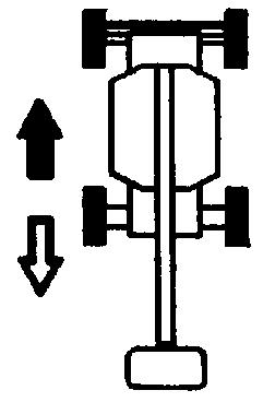
9 SECTION 1 - SAFETY PRECAUTIONS SECTION 1. SAFETY PRECAUTIONS 1.1 GENERAL This section prescribes the proper and safe practices for major areas of machine usage. In order to promote proper usage of the machine, it is mandatory that a daily routine be established based on instructions given in this section. A maintenance program must be also be established by a qualified person and must be followed to ensure that the machine is safe to operate. The owner/user/operator of the machine should not accept operating responsibility until this manual has been read and understood, and operation of the machine, under the supervision of an experienced and qualified person, has been completed. Owner/user/operator must be familiar with Sections 6, 7, 8, 9, and 10 of ANSI A These sections contain the responsibilities of the owner, users, operators, lessors and lessees concerning safety, training, inspection, maintenance, application and operation. If there is a question on application and or operation, JLG Industries Inc., should be consulted. 1.2 DRIVING/TOWING Before driving the machine, the user must be familiar with the drive, steer and stopping characteristics. This is especially important when driving in close quarters. The user should be familiar with the driving surface before driving. The surface should be firm and level and grades should not exceed the allowable grade for the machine. NOTE: Remember that the key to safe and proper usage is common sense and its careful application. The machine is not equipped with provisions for towing. Refer to Section 6 for emergency towing procedures. SPECIAL NOTE: FAILURE TO COMPLY WITH SAFETY PRECAUTIONS LISTED IN THIS SECTION AND ON THE MACHINE COULD RESULT IN MACHINE DAMAGE, PERSONNEL INJURY OR DEATH, AND IS A SAFETY VIOLATION. MODIFICATION OR ALTERATION OF AN AERIAL PLATFORM SHALL BE MADE ONLY WITH PRIOR WRITTEN PERMISSION OF THE MANUFACTURER JLG Lift 1-1
10 SECTION 1 - SAFETY PRECAUTIONS Table 1-1. Minimum Safe Approach Distances (M.S.A.D.) to energized (exposed or insulated) power lines and parts Voltage Range (Phase to Phase) MINIMUM SAFE APPROACH DISTANCE in Feet (Meters) 0 to 300V AVOID CONTACT Over 300V to 50 KV 10 (3) Over 50KV to 200 KV 15 (5) Over 200 KV to 350 KV 20 (6) Over 350 KV to 500 KV 25 (8) Over 500 KV to 750 KV 35 (11) Over 750 KV to 1000 KV 45 (14) DANGER: DO NOT maneuver machine or personnel inside PROHIBITED ZONE. ASSUME all electrical parts and wiring are ENERGIZED unless known otherwise. 1.3 ELECTROCUTION HAZARD FROM CONTACT WITH OR PROXIMITY TO AN ELEC- TRICALLY CHARGED CONDUCTOR. MAINTAIN A CLEARANCE OF AT LEAST 10 FEET (3 M) BETWEEN ANY PART OF THE MACHINE OR ITS LOAD AND ANY ELECTRICAL LINE OR APPARATUS CARRYING UP TO 50,000 VOLTS. ONE FOOT ADDI- TIONAL CLEARANCE IS REQUIRED FOR EVERY ADDITIONAL 30,000 VOLTS OR LESS. 1.4 PRE-OPERATIONAL MAINTAIN SAFE CLEARANCE FROM ELECTRICAL LINES AND APPARATUS. ALLOW FOR BOOM SWAY, ROCK OR SAG AND ELECTRICAL LINE SWAYING. THE MACHINE DOES NOT PROVIDE PROTECTION READ YOUR MANUAL. UNDERSTAND WHAT YOU VE READ - THEN BEGIN OPERATIONS. ALLOW ONLY AUTHORIZED AND QUALIFIED PER- SONNEL TO OPERATE MACHINE WHO HAVE DEM- ONSTRATED THAT THEY UNDERSTAND SAFE AND PROPER OPERATION AND MAINTENANCE OF THE UNIT. 1-2 JLG Lift
11 SECTION 1 - SAFETY PRECAUTIONS AN OPERATOR MUST NOT ACCEPT OPERATING RESPONSIBILITIES UNTIL ADEQUATE TRAINING HAS BEEN GIVEN BY COMPETENT AND AUTHORIZED PERSONS. BEFORE OPERATION, CHECK WORK AREA FOR OVERHEAD ELECTRIC LINES, MACHINE TRAFFIC SUCH AS BRIDGE CRANES, HIGHWAY, RAILWAY AND CONSTRUCTION EQUIPMENT. NEVER DISABLE OR MODIFY THE FOOTSWITCH OR ANY OTHER SAFETY DEVICE. ANY UNAUTHORIZED MODIFICATION OF THE MACHINE IS A SAFETY VIO- LATION AND IS A VIOLATION OF OSHA REGULA- TIONS AND ANSI STANDARDS. PRECAUTIONS TO AVOID ALL KNOWN HAZARDS IN THE WORK AREA MUST BE TAKEN BY THE OPERA- TOR AND HIS SUPERVISOR BEFORE STARTING THE WORK. DO NOT OPERATE THIS MACHINE UNLESS IT HAS BEEN SERVICED AND MAINTAINED ACCORDING TO THE MANUFACTURERS SPECIFICATIONS AND SCHEDULE. ENSURE DAILY INSPECTION AND FUNCTION CHECK IS PERFORMED PRIOR TO PLACING MACHINE INTO OPERATION. DO NOT OPERATE MACHINE WHEN WIND CONDI- TIONS EXCEED 30 MPH (48 KMH). NEVER OPERATE BOOM FUNCTIONS (TELE, SWING, LIFT) WHEN MACHINE IS ON A TRUCK, OTHER VEHI- CLE, OR ABOVE GROUND STRUCTURE. THIS MACHINE CAN BE OPERATED IN NOMINAL AMBIENT TEMPERATURES OF 0 F TO 104 F (-20 C TO 40 C). CONSULT FACTORY TO OPTIMIZE OPER- ATION OUTSIDE THIS RANGE. APPROVED HEAD GEAR MUST BE WORN BY ALL OPERATING AND GROUND PERSONNEL JLG Lift 1-3
12 SECTION 1 - SAFETY PRECAUTIONS. ALWAYS POSITION BOOM OVER REAR (DRIVE) AXLE IN LINE WITH DIRECTION OF TRAVEL. REMEMBER, IF BOOM IS OVER FRONT (STEER) AXLE, DIRECTION OF STEER AND DRIVE MOVEMENT WILL BE OPPO- SITE FROM NORMAL OPERATION. READ AND OBEY ALL DANGERS, WARNINGS, CAU- TIONS AND OPERATING INSTRUCTIONS ON MACHINE AND IN THIS MANUAL. BE FAMILIAR WITH LOCATION AND OPERATION OF GROUND STATION CONTROLS. ALWAYS USE THREE POINT CONTACT WHEN ENTERING OR EXITING THE MACHINE. FACE THE MACHINE WHEN YOU ENTER OR LEAVE. THREE POINT CONTACT MEANS THAT TWO HANDS AND ONE FOOT OR ONE HAND AND TWO FEET ARE IN CONTACT WITH THE MACHINE AT ALL TIMES DUR- ING MOUNT AND DISMOUNT. 1.5 DRIVING DO NOT USE DRIVE FUNCTION TO POSITION PLAT- FORM CLOSE TO OBSTACLES. USE BOOM FUNC- TION INSTEAD. WHEN DRIVING IN HIGH SPEED, SWITCH TO LOW SPEED BEFORE STOPPING. TRAVEL GRADES IN LOW DRIVE, HIGH ENGINE ONLY. DO NOT USE HIGH SPEED DRIVE WHEN IN RESTRICTED OR CLOSE QUARTERS, OR WHEN DRIVING IN REVERSE. BE AWARE OF STOPPING DISTANCES WHEN TRAV- ELING IN HIGH AND LOW SPEEDS. ALWAYS POST A LOOKOUT AND SOUND HORN WHEN DRIVING IN AREAS WHERE VISION IS OBSTRUCTED. KEEP NON-OPERATING PERSONNEL AT LEAST 6 FEET (2 M) AWAY FROM MACHINE DURING DRIVING OPERATIONS. WATCH FOR OBSTRUCTIONS AROUND MACHINE AND OVERHEAD WHEN DRIVING. 1-4 JLG Lift

13 SECTION 1 - SAFETY PRECAUTIONS 1.6 OPERATION. READ YOUR MANUAL. UNDERSTAND WHAT YOU VE READ - THEN BEGIN OPERATIONS. CHECK TRAVEL PATH FOR PERSONS, HOLES, BUMPS, DROP-OFFS, OBSTRUCTIONS, DEBRIS, AND COVERINGS WHICH MAY CONCEAL HOLES AND OTHER HAZARDS. TRAVEL IS PERMITTED ON GRADES AND SIDES- LOPES NO GREATER THAN THOSE INDICATED IN WARNING PLACARD AT MACHINE PLATFORM. OPERATION WITH BOOM RAISED IS RESTRICTED TO FIRM, LEVEL AND UNIFORM SURFACE. DO NOT TRAVEL ON SOFT OR UNEVEN SURFACES, AS TIPPING WILL OCCUR. ENSURE THAT GROUND CONDITIONS ARE ADE- QUATE TO SUPPORT THE MAXIMUM TIRE LOAD. DO NOT DRIVE MACHINE NEAR PITS, LOADING DOCKS OR OTHER DROP-OFFS. PRIOR TO ENTERING AND EXITING PLATFORM AT GROUND LEVEL, FULLY LOWER THE BOOM. EXTEND BOOM UNTIL END OF FLY BOOM CON- TACTS GROUND. WITH BOOM LIFT IN THIS CONFIG- URATION, ENTER AND/OR EXIT PLATFORM THROUGH GATE OPENING. OSHA REQUIRES ALL PERSONS IN THE PLATFORM TO WEAR LANYARDS WITH AN APPROVED FALL PROTECTION DEVICE. SECURE LANYARD TO DES- IGNATED LANYARD ATTACH POINT ON PLATFORM. KEEP GATE CLOSED AT ALL TIMES. TO AVOID FALLING - USE EXTREME CAUTION WHEN ENTERING OR LEAVING PLATFORM ABOVE GROUND. ENTER OR EXIT THRU GATE ONLY. PLAT- FORM FLOOR MUST BE WITHIN 1 FOOT (30 CM) OF ADJACENT - SAFE AND SECURE - STRUCTURE. ALLOW FOR PLATFORM VERTICAL MOVEMENT AS WEIGHT IS TRANSFERRED TO OR FROM PLAT- FORM JLG Lift 1-5


14 SECTION 1 - SAFETY PRECAUTIONS TRANSFERS BETWEEN A STRUCTURE AND THE AERIAL PLATFORM EXPOSE OPERATORS TO FALL HAZARDS. THIS PRACTICE SHOULD BE DISCOUR- AGED WHEREVER POSSIBLE. WHERE TRANSFER MUST BE ACCOMPLISHED TO PERFORM THE JOB TWO LANYARDS WITH AN APPROVED FALL PRO- TECTION DEVICE WILL BE USED. ONE LANYARD SHOULD BE ATTACHED TO THE AERIAL PLATFORM. THE OTHER TO THE STRUCTURE. THE LANYARD THAT IS ATTACHED TO THE AERIAL PLATFORM SHOULD NOT BE DISCONNECTED UNTIL SUCH TIME AS THE TRANSFER TO THE STRUCTURE IS COMPLETE. OTHERWISE, DO NOT STEP OUTSIDE OF PLATFORM. DO NOT ADD NOTICE BOARDS OR SIMILAR ITEMS TO THE PLATFORM. ADDITION OF SUCH ITEMS INCREASES THE EXPOSED WIND AREA OF THE MACHINE. NEVER POSITION LADDERS, STEPS, OR SIMILAR ITEMS ON UNIT TO PROVIDE ADDITIONAL REACH FOR ANY PURPOSE. WHEN RIDING IN OR WORKING FROM PLATFORM, BOTH FEET MUST BE FIRMLY POSITIONED ON THE FLOOR. KEEP OIL, MUD AND SLIPPERY SUBSTANCES CLEANED FROM FOOTWEAR AND PLATFORM FLOOR. NEVER "WALK" THE BOOM TO GAIN ACCESS TO OR LEAVE PLATFORM. NEVER PLACE HANDS OR ARMS IN TOWER BOOM OR UPRIGHT MECHANISM. KEEP ALL NON-OPERATING PERSONNEL AT LEAST 6 FEET (2 M) AWAY FROM THE MACHINE AT ALL TIMES. IF PLATFORM OR BOOM IS CAUGHT SO THAT ONE OR MORE WHEELS ARE OFF THE FLOOR, ALL PER- SONNEL MUST BE REMOVED FROM PLATFORM BEFORE ATTEMPTING TO FREE MACHINE. USE CRANES, FORKLIFT TRUCKS OR OTHER EQUIP- MENT TO REMOVE PERSONNEL AND STABILIZE MACHINE MOTION, IF NECESSARY. THE OPERATOR IS RESPONSIBLE TO AVOID OPER- ATING MACHINE OVER GROUND PERSONNEL AND TO WARN THEM NOT TO WORK, WALK OR STAND UNDER A RAISED BOOM OR PLATFORM. POSITION BARRICADES ON FLOOR IF NECESSARY. 1-6 JLG Lift
15 SECTION 1 - SAFETY PRECAUTIONS. ENSURE MACHINE IS POSITIONED ON A FIRM, LEVEL AND UNIFORM SUPPORTING SURFACE BEFORE RAISING OR EXTENDING BOOM. CHECK CLEARANCES ABOVE, ON SIDES AND BOT- TOM OF PLATFORM WHEN RAISING, LOWERING, SWINGING, AND TELESCOPING BOOM. EXERCISE EXTREME CAUTION AT ALL TIMES TO PREVENT OBSTACLES FROM STRIKING OR INTER- FERING WITH OPERATING CONTROLS AND PER- SONS IN PLATFORM. ENSURE THAT OPERATORS OF OTHER OVERHEAD AND FLOOR MACHINES ARE AWARE OF THE AERIAL PLATFORMS PRESENCE. DISCONNECT POWER TO OVERHEAD CRANES. POSITION BARRICADES ON FLOOR IF NECESSARY. NEVER "SLAM" A CONTROL SWITCH OR LEVER THROUGH NEUTRAL TO THE OPPOSITE DIRECTION. ALWAYS RETURN SWITCH TO NEUTRAL AND STOP; THEN MOVE SWITCH TO THE DESIRED POSITION. OPERATE LEVERS WITH SLOW, EVEN PRESSURE. DO NOT CARRY MATERIALS ON PLATFORM RAILING UNLESS APPROVED BY JLG INDUSTRIES INC. NEVER PUSH OR PULL THE MACHINE OR OTHER OBJECTS BY TELESCOPING THE BOOM. NEVER USE BOOM FOR ANY PURPOSE OTHER THAN POSITIONING PERSONNEL, THEIR TOOLS AND EQUIPMENT. NEVER EXCEED MANUFACTURERS RATED PLAT- FORM CAPACITY - REFER TO CAPACITY DECAL ON MACHINE. DISTRIBUTE LOADS EVENLY ON PLAT- FORM FLOOR. NEVER OPERATE A MALFUNCTIONING MACHINE. IF A MALFUNCTION OCCURS, SHUT DOWN THE MACHINE, RED TAG IT, AND NOTIFY PROPER AUTHORITIES. DO NOT REMOVE, MODIFY, OR DISABLE FOOT- SWITCH BY BLOCKING OR ANY OTHER MEANS. DO NOT ASSIST A STUCK OR DISABLED MACHINE BY PUSHING OR PULLING EXCEPT BY PULLING AT CHASSIS TIE-DOWN LUGS. NEVER ATTEMPT USING BOOM AS A CRANE. STRUCTURAL DAMAGE OR TIPPING MAY OCCUR. STOW BOOM AND SHUT OFF ALL POWER BEFORE LEAVING MACHINE. NO STUNT DRIVING OR HORSEPLAY IS PERMITTED JLG Lift 1-7
16 SECTION 1 - SAFETY PRECAUTIONS NEVER ATTEMPT TO FREE A MACHINE STUCK IN SOFT GROUND OR ASSIST A MACHINE UP A STEEP HILL OR RAMP BY USING BOOM "LIFT", "TELE- SCOPE", OR "SWING" FUNCTIONS. NEVER ATTACH WIRE, CABLE, OR ANY SIMILAR ITEMS TO PLATFORM. DO NOT PLACE BOOM OR PLATFORM AGAINST ANY STRUCTURE TO STEADY PLATFORM OR SUPPORT STRUCTURES. DO NOT USE THE LIFT, SWING, OR TELESCOPE FUNCTIONS FOR THE BOOM, TO MOVE EITHER THE MACHINE OR OTHER OBJECTS. HYDRAULIC CYLINDERS SHOULD NEVER BE LEFT FULLY EXTENDED OR RETRACTED FOR ANY LENGTH OF TIME. ALWAYS "BUMP" CONTROL IN OPPOSITE DIRECTION SLIGHTLY WHEN FUNCTION BEING USED REACHES END OF TRAVEL. THIS APPLIES TO MACHINES IN OPERATION OR IN STOWED MODE. DO NOT OPERATE ANY MACHINE ON WHICH DAN- GER, WARNING, CAUTION OR INSTRUCTION PLAC- ARDS OR DECALS ARE MISSING OR ILLEGIBLE. MACHINE MUST ALWAYS BE SHUT DOWN WHEN REFUELING. NO SMOKING IS MANDATORY. NEVER REFUEL DURING AN ELECTRICAL STORM. ENSURE THAT FUEL CAP IS CLOSED AND SECURE AT ALL OTHER TIMES. 1.7 TOWING AND HAULING DO NOT TOW A MACHINE EXCEPT IN AN EMER- GENCY. SEE SECTION 6 FOR EMERGENCY TOWING PROCEDURES. LOCK TURNTABLE BEFORE TRAVELING LONG DIS- TANCES OR BEFORE HAULING MACHINE ON A TRUCK OR TRAILER. 1-8 JLG Lift
17 SECTION 2 - PREPARATION AND INSPECTION SECTION 2. PREPARATION AND INSPECTION 2.1 GENERAL This section provides the necessary information needed by those personnel that are responsible to place the machine in operation readiness, and lists checks that are performed prior to use of the machine. It is important that the information contained in this section be read and understood before any attempt is made to operate the machine. Ensure that all the necessary inspections have been completed successfully before placing the machine into service. These procedures will aid in obtaining maximum service life and safe operation. SINCE THE MACHINE MANUFACTURER HAS NO DIRECT CON- TROL OVER THE FIELD INSPECTION AND MAINTENANCE, SAFETY IS THE RESPONSIBILITY OF THE OWNER/OPERATOR. 2.2 PREPARATION FOR USE Before a new machine is put into operation it must be carefully inspected for any evidence of damage resulting from shipment and inspected periodically thereafter, as outlined in Delivery and Frequent Inspection (Section 2.3, Delivery and Frequent Inspection). During initial start-up and run, the unit should be thoroughly checked for hydraulic leaks. A check of all components should be made to ensure their security. All preparation necessary to place the machine in operation readiness status is the responsibility of management personnel. Preparation requires good common sense, (i.e. telescope works smoothly and brakes operate properly) coupled with a series of visual inspections. The mandatory requirements are given in the Daily Walk Around Inspection (Section 2.4, Daily Walk-Around Inspection). It should be assured that the items appearing in the Delivery and Frequent Inspection and Functional Check are complied with prior to putting the machine into service. 2.3 DELIVERY AND FREQUENT INSPECTION NOTE: This machine requires frequent safety and maintenance inspections by an authorized JLG Dealer. A decal located on the turntable provides a place to record (stamp)annual Inspection dates. Check decal and notify dealer if inspection is overdue. NOTE: An annual inspection shall be performed on the aerial platform no later than thirteen (13) months from the date of the prior annual inspection. The inspection shall be performed by person(s) qualified as a mechanic on the specific make and model of aerial platform. The following checklist provides a systematic inspection to assist in detecting defective, damaged, or improperly installed parts. The checklist denotes the items to be inspected and conditions to examine. Frequent inspection shall be performed every 3 months or 150 hours whichever comes first, or more often when required by environment, severity, and frequency of usage. This inspection checklist is also applicable and must be followed for all machines that have been in storage or for all machines that will be exposed to harsh or changing climates. These checks are also performed after maintenance has been performed on the machine. Chassis 1. Check front tire and wheel assemblies for loose or worn spindles, components and hardware for security, tires for wear and damage. 2. Check steering assembly for loose or bent tie rod, cylinder and hydraulic lines for leaks and security, and hardware for proper installation. 3. Check rear tire and wheel assemblies for security, tires for wear and damage. 4. Check drive hubs, hydraulic motors, brakes and hydraulic lines for damage and leaks. 5. Check oil level in drive hub by removing pipe plug on side and feeling for oil level. (Contact Service Personnel for assistance if needed). NOTE: Torque hubs should be one-half full of lubricant. 6. Check 4WS steering assembly (if equipped) for loose or bent tie rod, cylinder and hydraulic lines for leaks and security, and hardware for proper installation. 7. Check counterbalance, flow divider valves, hydraulic swivel assembly and lines for visible damage, evidence of leakage, and security and electrical connections for corrosion and tightness JLG Lift 2-1
18 SECTION 2 - PREPARATION AND INSPECTION 8. Check extending axle assemblies for evidence of leakage and security; pressure lines for abnormal chafing drive hubs, hydraulic motors, brakes and hydraulic lines for damage and leaks. 9. Check extending axles for visible damage and loose or missing parts. 10. Check oscillating axle (if equipped) for loose, missing and worn parts, pivot pin and lockout cylinder pins for security, lockout cylinders and hydraulic hoses for damage and leaks. Turntable 1. Check turntable and turntable lock for damage, loose or missing parts, and security. Check swing drive hub, hydraulic motor, and brake for damage, loose or missing parts, hydraulic lines and component housings for evidence of leakage; pinion for proper mesh with swing gear. 2. Check swing bearing for damage, wear, lubrication and loose or missing bearing bolts. 3. Check solenoid valves and hydraulic lines for damage, leakage, security and electrical connections for tightness and evidence of corrosion. 4. Check ground controls for damage, loose or missing parts, security, electrical connections for evidence of corrosion and tightness and wiring for insulation damage. Assure that all switches function properly. 5. Check manual descent valves for visible damage, evidence of leakage and security. Assure that valves function properly. 6. Check battery for damage, loose or missing vent caps, electrical connections for tightness, and evidence of corrosion, holddown brackets for tightness, and electrolyte for proper water level. Add only clean distilled water to battery. 7. Check engine and accessories for damage, loose or missing parts, leakage and security. Check throttle solenoid and linkage for damage, electrical connections for tightness, and evidence of corrosion and wiring for insulation damage. 8. Check fuel lines for damage, leakage and security. 9. Check all access doors for damage, proper operation of latches, props and security. 10. Check fuel tank for damage, leakage and filler cap for security. 11. Check hydraulic reservoir and hydraulic lines for damage, leakage and security. NOTE: JLG recommends replacing the hydraulic filter element after the first 50 hours of operation and then every 300 hours thereafter, unless system indicator require earlier replacement. 12. Check all cylinder pin and shaft retaining hardware for security and wear. 13. Check all electrical cables for defects, damage, loose or corroded connections. Boom 1. Check all cylinder pin and shaft retaining hardware for security and wear. 2. Check hydraulic lines, electrical cable and track assemblies for damage, missing parts and security. 3. Check lift cylinder and cross pins and hydraulic lines for damage, wear, leakage and security. 4. Check boom pivot pins for damage, wear, and security. 5. Check hydraulic line and electrical cable track assembly for visible damage, loose or missing parts, and security. 6. Check boom for damage, missing parts and security. 7. Check boom wear pads for damage, wear and security. 8. Check boom telescope cylinder and cross pins and hydraulic lines for damage, wear, leakage and security. 9. Check platform leveling cylinder and cross pins and hydraulic lines for damage, wear, leakage and security. 10. Check boom/platform pivot pin for damage, wear and security. 11. Check horizontal and capacity limit switches mounted on turntable for security of mounting, damage to switch arms and rollers; and for debris. 12. Check boom tape for correct length, tearing, or defacing at any point. Extend-A-Reach (If Equipped) 1. Check the slave cylinder, weld link and cross pins, and lines for visible damage, wear, lubrication, evidence of leakage, and security. 2. Check extend-a-reach for visible damage, loose or missing parts, and security. 3. Check hydraulic lines and electrical cable for damage, missing parts and security. 2-2 JLG Lift
19 SECTION 2 - PREPARATION AND INSPECTION Figure 2-1. Machine Nomenclature JLG Lift 2-3
20 SECTION 2 - PREPARATION AND INSPECTION Platform 1. Check platform and control console for damage, loose or missing parts, and security. 2. \Check control switches and levers for damage, loose or missing parts and security. Assure that all levers function properly. 3. Check control switches, levers and electrical connections for tightness and evidence of corrosion, and wiring for defects and chafing damage. Assure that all switches function properly. 4. Check access gate hinges and latch for proper operation, damage and security. 5. Check platform rotator mechanism for proper operation, damage, security. Check hydraulic lines for leakage, damage and security. NOTE: Check all DANGER, WARNING, CAUTION and INSTRUCTION placards for legibility and security on the entire machine. Torque Requirements The Torque Chart (See Figure 2-6.) consists of standard torque values based on bolt diameter and grade, also specifying dry and wet torque values in accordance with recommended shop practices. This chart is provided as an aid to the operator in the event he/she notices a condition that requires prompt attention during the walk-around inspection or during operation, until the proper service personnel can be notified. The Service and Maintenance manual provides specific torque values and periodic maintenance procedures with a listing of individual components. Utilizing this Torque Chart in conjunction with the preventive maintenance section in the Service and Maintenance manual will enhance safety, reliability, and performance of the machine. 2.4 DAILY WALK-AROUND INSPECTION It is the operator s responsibility to inspect the machine before the start of each workday. It is recommended that each operator inspect the machine before operation, even if the machine has already been put into service under another operator. This Daily Walk-Around Inspection is the preferred method of inspection. (See Figure 2-2.) 2. Placards. Keep all information and operating placards clean and unobstructed. Cover when spray painting or shot blasting to protect legibility. 3. Operator s and Safety Manual. Ensure a copy of this manual and the ANSI A Responsibilities, are enclosed in the manual storage box. 4. Machine Log. Ensure a machine operating record or log is kept, check to see that it is current and that no entries have been left uncleared, leaving machine in an unsafe condition for operation. 5. Start each day with a full fuel tank. TO AVOID INJURY, DO NOT OPERATE A MACHINE UNTIL ALL MALFUNCTIONS HAVE BEEN CORRECTED. USE OF A MALFUNC- TIONING MACHINE IS A SAFETY VIOLATION. TO AVOID POSSIBLE INJURY, BE SURE MACHINE POWER IS OFF DURING WALK-AROUND INSPECTION. NOTE: Check boom horizontal limit switch for proper operation and security, both visually and manually. Switch must shut down high engine and high drive speed when boom is raised above horizontal: 6. Check platform footswitch for proper operation. Switch must be released to start engine and depressed to operate machine. 7. Check that drive brakes hold when machine is driven up a grade and stopped. NOTE: On new machines, those recently overhauled, or after changing hydraulic oil, operate all systems a minimum of two complete cycles and recheck oil level in reservoir. 8. Assure that all items requiring lubrication are serviced. Refer to Figure 2-5., Lubrication Point Location, for specific requirements. In addition to the Daily Walk-Around Inspection, be sure to include the following as part of the daily inspection: 1. Overall cleanliness. Check all standing surfaces for oil, fuel and hydraulic oil spillage and foreign objects. Ensure overall cleanliness. 2-4 JLG Lift
21 SECTION 2 - PREPARATION AND INSPECTION Figure 2-2. Daily Walk-Around Inspection Diagram JLG Lift 2-5
22 SECTION 2 - PREPARATION AND INSPECTION GENERAL Begin the Walk-Around Inspection at Item 1, as noted on the diagram. Continue to the right (counterclockwise viewed from top) checking each item in sequence for the conditions listed in the Walk-Around Inspection Checklist. TO AVOID INJURY, DO NOT OPERATE A MACHINE UNTIL ALL MALFUNCTIONS HAVE BEEN CORRECTED. USE OF A MAL- FUNCTIONING MACHINE IS A SAFETY VIOLATION. TO AVOID POSSIBLE INJURY, BE SURE MACHINE POWER IS OFF DUR- ING WALK-AROUND INSPECTION. NOTE: Do not overlook visual inspection of chassis underside. Checking this area often results in discovery of conditions which could cause extensive machine damage. 1. Platform Assembly - No loose or missing parts, no visible damage. Lock bolts in place. Footswitch in good working order, not modified, disabled or blocked. Check area of fly boom nose section above and under platform slave level cylinder for accumulation of foreign material. Remove any foreign material present. 2. Platform Control Console - Switches and levers return to neutral and are properly secured, no loose or missing parts, no visible damage, decals/placards secure and legible, control marking legible. 3. Slave Leveling Cylinder, Extend-A-Reach - Properly secured, no visible damage, no evidence of leakage. (If equipped on Extend-A-Reach) 4. Extend-A-Reach Lift Cylinder - Properly secured, no visible damage, or signs of leakage, evidence of proper lubrication. (If equipped on Extend-A- Reach) 5. Extend-A-Reach Pivot - No loose, damaged, or missing parts, evidence of proper lubrication. (If equipped on Extend-A-Reach) 6. Hose and Cable Guards/Clamps - Properly secured, no visible damage. 7. Power Track - No loose, damaged or missing parts, no visible damage. 8. Drive Motor and Brake, Right Rear - No visible damage, no evidence of leakage. 9. Drive Hub, Right Rear - No visible damage, no evidence of leakage. 10. Wheel/Tire Assembly, Right Rear - Properly secured, no loose or missing lug nuts, no visible damage. 11. Extendable Axle - Lock pins in place, properly secured. Check both sides. 12. Swing Drive Motor and Brake - No visible damage, no evidence of leakage. 13. Fuel Supply - Fuel filler cap secure. Tank - no visible damage; no evidence of leaks. 14. Cowling and Latches - All cowling and latches in working condition, properly secured, no loose or missing part. 15. Control Valve Compartment - No loose or missing parts; evidence of leakage; unsupported wires or hoses; damaged or broken wires. 16. Extendable Axle - Lock pins in place, properly secured. Check both sides. 17. Hydraulic Oil Supply - Recommended oil level in sight gauge. (Check level with cold oil, systems shut down, machine in stowed position) Cap in place and secure. 18. Hydraulic Oil Filter Housing - Housing secure; no visible damage or signs of leakage. 19. Hydraulic Oil Breather - Element in place, not clogged, no signs of overflow. 20. Wheel/Tire Assembly, Right Front - Properly secured, no loose or missing lug nuts, no visible damage. 21. Turntable Springs - Properly secured, no loose or missing nuts or bolts. 22. Ground Controls - Switches operable, no visible damage, decals secure and legible. 23. Engine Air Filter - No loose or missing parts, no visible damage, element clean. 24. Tie Rod and Steering Linkage - No loose or missing parts, no visible damage. Tie rod end studs locked. 25. Wheel/Tire Assembly, Left Front - Properly secured, no loose or missing lug nuts, no visible damage. 26. Engine Oil Supply - Full mark on dipstick; filler cap secure. Figure 2-3. Daily Walk-Around Inspection Points - Sheet JLG Lift
23 SECTION 2 - PREPARATION AND INSPECTION 27. Muffler and Exhaust System - Properly secured, no evidence of leakage 28. Cowling and Latches, Right Side - All cowling and latches in working condition, properly secured, no loose or missing part. 29. Turntable Bearing and Pinion - No loose or missing hardware; no visible damage, evidence of proper lubrication. No evidence of loose bolts or looseness between bearing and structure. 30. Battery - Proper electrolyte levels; cables tight, no visible damage or corrosion. 31. Frame - No visible damage, no loose or missing hardware (top and underside). 32. Drive Hub, Left Rear - No visible damage, no evidence of leakage. 33. Wheel/Tire Assembly, Left Rear - Properly secured, no loose or missing lug nuts, no visible damage. 34. Drive Motor and Brake, Left Rear - No visible damage, no evidence of leakage. 35. Boom Sections - No visible damage; wear pads secure. All cylinders - rod end shafts and barrel-end shafts properly secured. 36. Rotator and Motor - Properly secured, no visible damage, no evidence of leakage. 37. Platform Pivot and Slave Cylinder Attach Pins - Properly secured; evidence of proper lubrication where applicable. Figure 2-4. Daily Walk-Around Inspection Points - Sheet JLG Lift 2-7
24 SECTION 2 - PREPARATION AND INSPECTION 2.5 DAILY FUNCTIONAL CHECK THE LOAD MANAGEMENT SYSTEM AND THE AXLES (PROPER EXTENSION AND RETRACTION) MUST BE CHECKED PRIOR TO ANY OTHER SYSTEMS AND/OR FUNCTIONS. A functional check of all systems should be performed, once the walk-around inspection is complete, in an area free of overhead and ground level obstructions. First, using the ground controls, check all functions controlled by the ground controls. Next, using the platform controls, check all functions controlled by the platform controls. TO AVOID SERIOUS INJURY, DO NOT OPERATE MACHINE IF ANY CONTROL LEVERS OR TOGGLE SWITCHES CONTROLLING PLATFORM MOVEMENTS DO NOT RETURN TO THE OFF OR NEU- TRAL POSITION WHEN RELEASED. TO AVOID COLLISION AND INJURY IF PLATFORM DOES NOT STOP WHEN A CONTROL SWITCH OR LEVER IS RELEASED, REMOVE FOOT FROM FOOTSWITCH OR USE EMERGENCY STOP TO STOP THE MACHINE. NOTE: Perform checks from ground controls first, where applicable, then from platform controls. 1. Axles, Extending and Retracting. a. From the ground control, activate the machine hydraulic system and raise the boom. Extend the boom no more than 8 feet (2.4 m). b. Position STEER/AXLES valve, located at the front of the frame to AXLES. c. Position boom over drive wheel end of machine. Remove axle lock pins. e. With the aid of an assistant, position EXTEND- ABLE AXLE/STEER switch located on platform control console to EXTEND until axles are fully extended and the AXLES SET light is on. Install axle lock pins. f. Position LIFT control to UP to lower the machine; elevate the boom sufficiently and reposition the boom over the steer wheel end of the machine. g. Remove the tie rod lock pins, steer cylinder lock pin, and axle lock pins. h. Position LIFT control to DOWN and hold until the steer wheels rise from the ground; it may be necessary to feather the LIFT control to maintain wheel elevation. i. With the aid of an assistant, position EXTEND- ABLE AXLE/STEER switch on platform console to EXTEND until axles are fully extended. j. Align steer wheels and insert tie rod lock pin, axle lock pins, and steer cylinder lock pins. k. Position LIFT control to UP to lower the machine steer wheels; position STEER/AXLES valve to STEER. l. Cycle the steer system in both directions to ensure the tie rods are properly locked. m. Remove any one of the axle lock pins. From the ground control, monitor the AXLES SET indicator and attempt to lift and telescope the boom. With an axle lock pin removed, you will not be able to lift the boom above horizontal or telescope out beyond 11.5 feet (3.5 m). At these positions, the AXLES SET indicator will not light, indicating the axles are not extended and locked. If the light does not illuminate when the axles are extended and set and the pins installed, contact a qualified service technician before continuing operation. DO NOT USE EXTEND-A-REACH (IF EQUIPPED) TO LIFT MACHINE WHEN EXTENDING AND RETRACTING AXLES. d. Position LIFT control to DOWN and hold until drive wheels rise from the ground; it may be necessary to feather the lift control to maintain drive wheel elevation. 2-8 JLG Lift
25 SECTION 2 - PREPARATION AND INSPECTION Figure 2-5. Lubrication Point Location JLG Lift 2-9
26 SECTION 2 - PREPARATION AND INSPECTION Table 2-1. Lubrication Chart Components Number/Type Lube Points Lube & Method Interval Hours Comments 1 Master Cylinder - Barrel End 1 Grease Fitting MPG - Pressure Gun 150 Remote Access 2 Master Cylinder - Rod End 1 Grease Fitting MPG - Pressure Gun Boom Pivot Bushings 2 Grease Fittings MPG - Pressure Gun Lift Cylinder - Rod End 1 Grease Fitting MPG - Pressure Gun Lift Cylinder - Barrel End 1 Grease Fitting MPG - Pressure Gun 150 Remote Access 6 Slave Cylinder - Rod End 1 Grease Fitting MPG - Pressure Gun Slave Cylinder - Shaft End 1 Grease Fitting MPG - Pressure Gun Extend-A-Reach Cylinder - Rod End 1 Grease Fitting MPG- Pressure Gun Extend-A-Reach Cylinder - Attach Pin 2 Grease Fittings MPG - Pressure Gun Platform Door Hinges 2 Grease Fittings MPG - Pressure Gun Platform Door Latch N/A SAE10 - Oil Can Rotary Platform Control Stand 2 Grease Fittings MPG - Pressure Gun Platform Attach Pin and Rotary Worm Gear 1 Grease Fitting Each MPG - Pressure Gun Drive Hubs Fill Plug EPGL - SAE90 150/1200 Check every 150 hrs. /Change every 1200 hrs. 15 Swing Bearing Gear N/A MPG - Brush Swing Bearing 1 Grease Fitting MPG - Pressure Gun Steer Spindles 2 Grease Fittings MPG - Pressure Gun Steer Cylinder - Rod End 1 Grease Fitting MPG - Pressure Gun Steer Cylinder - Barrel End 1 Grease Fitting MPG - Pressure Gun Tie Rod Ends 2 Grease Fittings MPG - Pressure Gun Extending Axle Beams N/A MPG - Brush Wheel Bearings N/A MPG - Repack Engine Crankcase Fill Cap EO-SAE30 10/300 Check daily/change every 300 hrs. 24 Engine Oil Filter N/A Replaceable Cartridge Door and Access Panel Hinges N/A SAE10 - Oil Can Hydraulic Fluid Fill Cap HO 10/1200 Check daily/change every 1200 hrs. 27 Hyd. Filter Element (Tank) N/A N/A 50/300 Replace filter after first 50 hrs. of operation, then every 300 hrs. thereafter 28 Hyd. Filter Element (Inline) N/A N/A 50/300 Replace filter after first 50 hrs. of operation, then every 300 hrs. thereafter 29 Telescope Cylinder Sheave 1 Grease Fitting MPG - Pressure Gun Extend Chain Sheave 1 Grease Fitting MPG - Pressure Gun Retract Chain Sheave 1 Grease Fitting MPG - Pressure Gun JLG Lift
27 SECTION 2 - PREPARATION AND INSPECTION Table 2-1. Lubrication Chart Components Number/Type Lube Points Lube & Method Interval Hours Comments 32 Boom Chains N/A Chain Lube/Hot Oil Dip 1200 Includes extend and retract chains 33 Turntable Pivot Pin 2 Grease Fittings MPG - Pressure Gun Extend-A-Reach Link Attach Pin 1 Grease Fitting MPG - Pressure Gun Extend-A-Reach Pivot Pin 2 Grease Fittings MPG - Pressure Gun 150 NOTES: Key to Lubricants: EO EPGL HO MPG t Engine Oil Extreme Pressure Gear Lube Hydraulic Fluid (Mobil #424 or equivalent) Multi-Purpose Grease 2. Load Management System. 110HX. NOTE: The blue light should illuminate when the ignition is turned on. a. Activate the hydraulic system from the ground controls. The blue light should illuminate when the SELECT SWITCH is in the ground position and the EMERGENCY STOP switch is in the ON position. b. Extend the boom at horizontal until the yellow band on the inner mid section is exposed from the base. The yellow light should illuminate at this point. c. Continue extending the boom until the red marking band on the inner mid section is exposed from the base section. The red light should illuminate at this point. d. Continue extending the boom until the white marking band on the inner mid section is exposed from the base section. The red light should blink and an audible alarm sound. Also the telescope out and lift down will not function in this mode. IF BOOM CONTINUES TO TELESCOPE BEYOND THE THIRD MARKING BAND, RETRACT THE BOOM, IMMEDIATELY SHUT DOWN MACHINE AND CONTACT A QUALIFIED SERVICE PER- SON. 100HX +10. NOTE: The blue light should illuminate when the ignition is turned on. a. Activate the hydraulic system from the ground controls. The blue light should illuminate when the SELECT SWITCH is in the ground position and the EMERGENCY STOP switch is in the ON position. b. Extend the boom until the red marking band on the inner mid section is exposed from the base section. The red light should illuminate at this point. c. Continue extending the boom until the white marking band on the inner mid section is exposed from the base section. The red light should blink and an audible alarm sound. Also the telescope out and lift down will not function in this mode. IF BOOM CONTINUES TO TELESCOPE BEYOND SECOND MARK- ING BAND, RETRACT THE BOOM, IMMEDIATELY SHUT DOWN MACHINE AND CONTACT A QUALIFIED SERVICE PERSON. 110HX/100HX+10. a. With the boom fully retracted, raise the boom to horizontal. b. Position the toggle switch located on the right side of the ground control box to the P position and hold. c. Extend the boom until it stops. The boom must stop on the white band on the mid boom section. Release the toggle switch. d. Retract the boom until tele out will function. The system is now reset. e. Position the toggle switch to the M position and hold JLG Lift 2-11
28 SECTION 2 - PREPARATION AND INSPECTION f. Extend the boom until it stops. The boom must stop on the white band on the mid boom section. IF BOOM CONTINUES TO TELESCOPE BEYOND SECOND MARK- ING BAND, RETRACT THE BOOM, IMMEDIATELY SHUT DOWN MACHINE AND CONTACT A QUALIFIED SERVICE PERSON. 3. Drive forward and reverse; check for proper operation. 4. Steer left and right; check for proper operation. 5. If equipped with 4 wheel steer, check rear steer left and right for proper operation. 6. If equipped, check platform rotator for smooth operation and assure platform will rotate 90 degrees in both directions from centerline of boom. 7. Raise, lower, and swing boom to LEFT and RIGHT a minimum of 45 degrees (Cycle function several times.) Check for smooth elevation and swing motion. 8. If equipped with Extend-A-Reach, raise and lower and swing Extend-A-Reach (Cycle functions several times). check for smooth elevation and swing motion. 9. Telescope boom in and out several cycles at various degrees of elevation lengths. Check for smooth telescope operation. 10. Check that platform automatic self-leveling system functions properly during raising and lowering of the boom. 11. Check platform level adjustment system for proper operation. NOTE: Turntable lock is on turntable facing platform. To disengage lock, pull snap pin from lock pin, lift lock pin up to unlock turntable. Return snap pin to lock pin to hold lock pin in the disengaged position. Reverse procedure to engage turntable lock. 12. Swing turntable to LEFT and RIGHT a minimum of 45 degrees. Check for smooth motion. 13. With the aid of an assistant to monitor the CHASSIS OUT OF LEVEL indicator light on the platform control console, manually activate the indicator light by compressing any one of the three tilt indicator mounting springs. If the light does not illuminate, shut down machine and contact a qualified service technician before continuing operation. 14. Footswitch. FOOTSWITCH MUST BE ADJUSTED SO THAT FUNCTIONS WILL OPERATE WHEN PEDAL IS APPROXIMATELY AT ITS CENTER OF TRAVEL. IF SWITCH OPERATES WITHIN LAST 1/4" OF TRAVEL, TOP OR BOTTOM, IT SHOULD BE ADJUSTED. a. Activate hydraulic system. By depressing footswitch. Operate TELESCOPE and hold control. Remove foot from footswitch, motion should stop. If it does not, shut down machine and contact a certified JLG service technician. b. With footswitch depressed, operate LIFT and hold control. Remove foot from footswitch, motion should stop. If it does not, shut down machine and contact a certified JLG service technician. c. With engine power shut down, depress the footswitch. Attempt to start engine. Engine should not attempt to start when footswitch is depressed. If starter engages or engine turns over, shut down machine and contact a certified JLG service technician. 15. Auxiliary Power. Operate each function control switch (e.g. TELE, LIFT and SWING) to assure that they function in both directions using auxiliary power instead of engine power. 16. Ground Controls. Place GROUND/PLATFORM SELECT switch to GROUND. Start engine. Platform controls should not operate. 2.6 TORQUE REQUIREMENTS The Torque Chart (See Figure 2-6.) consists of standard torque values based on bolt diameter and grade, also specifying dry and wet torque values in accordance with recommended shop practices. This chart is provided as an aid to the operator in the event a condition is noticed that requires prompt attention during the walk-around inspection or during operation until the proper service personnel can be notified. The Service and Maintenance manual provides specific torque values and periodic maintenance procedures with a listing of individual components. Utilizing this Torque Chart in conjunction with the preventive maintenance section in the Service and Maintenance manual, will enhance safety, reliability and performance of the machine JLG Lift
29 SECTION 2 - PREPARATION AND INSPECTION 2.7 BATTERY MAINTENANCE TO AVOID INJURY FROM AN EXPLOSION, DO NOT SMOKE OR ALLOW SPARKS OR A FLAME NEAR BATTERY DURING SERVIC- ING. ALWAYS WEAR EYE PROTECTION WHEN SERVICING BATTER- IES. Battery Maintenance 1. The battery is maintenance free except for occasional battery terminal cleaning, as noted in the following. 2. Remove battery cables from each battery post one at a time, negative first. Clean cables with acid neutralizing solution (e.g. baking soda and water or ammonia) and wire brush. Replace cables and/or cable clamp bolts as required. 3. Clean battery post with wire brush then re-connect cable to post. Coat non-contact surfaces with mineral grease or petroleum jelly (Vaseline). 4. When all cables and terminal posts have been cleaned, ensure all cables are properly positioned and are not pinched. Close battery compartment cover JLG Lift 2-13
30 SECTION 2 - PREPARATION AND INSPECTION Figure 2-6. Torque Chart 2-14 JLG Lift
31 SECTION 3 - USER RESPONSIBILITIES AND MACHINE CONTROL SECTION 3. USER RESPONSIBILITIES AND MACHINE CONTROL 3.1 GENERAL SINCE THE MANUFACTURER HAS NO DIRECT CONTROL OVER MACHINE APPLICATION AND OPERATION, CONFORMANCE WITH GOOD SAFETY PRACTICES IN THESE AREAS IS THE RESPONSI- BILITY OF THE USER AND HIS/HER OPERATING PERSONNEL. This section provides the necessary information needed to understand control functions. Included in this section are the operating characteristics and limitations, and functions and purposes of controls and indicators. It is important that the operator read and understand the proper procedures before operating the machine. These procedures will aid in obtaining optimum lift service and safe operation. 3.2 PERSONNEL TRAINING The aerial platform is a personnel handling device; therefore it is essential that it be operated and maintained only by authorized and qualified personnel who have demonstrated that they understand the proper use and maintenance of the machine. It is important that all personnel who are assigned to and responsible for the operation and maintenance of the machine undergo a thorough training program and check out period in order to become familiar with the characteristics prior to operating the machine. In addition, personnel operating the machine should be familiar with ANSI standard A Responsibilities Section. This outlines the responsibilities of the owners, users, operators, lessors and lessees concerning safety, training, inspection, maintenance, application and operation. Persons under the influence of drugs or alcohol or who are subject to seizures, dizziness or loss of physical control must not be permitted to operate the machine. Operator Training Operator training must include instruction in the following areas: 3. Knowledge and understanding of all safety work rules of the employer and of Federal, State and local statutes, including training in the recognition and avoidance of potential hazards in the work place; with particular attention to the work to be performed. 4. Proper use of all required personnel safety equipment, in particular the wearing of a safety harness or other approved fall protection devices with a lanyard attached to the platform at all times. 5. Sufficient knowledge of the mechanical operation of the machine to recognize a malfunction or potential malfunction. 6. The safest means to operate the machine where overhead obstructions, other moving equipment, and obstacles, depressions, holes, drop-offs, etc. on the supporting surface exist. 7. Means to avoid the hazards of unprotected electrical conductors. 8. Any other requirements of a specific job or machine application. Training Supervision Training must be done under the supervision of a qualified person in an open area free of obstructions until the trainee has developed the ability to safely control a machine in congested work locations. Operator Responsibility The operator must be instructed that he/she has the responsibility and authority to shut down the machine in case of a malfunction or other unsafe condition of either the machine or the job site and to request further information from his/her supervisor or an authorized JLG Distributor before proceeding. NOTE: Manufacturer or distributor will provide qualified persons for training assistance with first unit(s) delivered and thereafter as requested by the user or his/her personnel. 1. Use and limitations of the platform controls, ground controls, emergency controls and safety systems. 2. Knowledge and understanding of this manual and of the control markings, instructions and warnings on the machine itself JLG Lift 3-1
32 SECTION 3 - USER RESPONSIBILITIES AND MACHINE CONTROL 3.3 OPERATING CHARACTERISTICS AND LIMITATIONS General A thorough knowledge of the operating characteristics and limitations of the machine is always the first requirement for any operator, regardless of the user s experience with similar types of equipment. Placards Important points to remember during operation are provided at the control stations by DANGER, WARNING, CAUTION, IMPORTANT and INSTRUCTION placards. This information is placed at various locations for the express purpose of alerting personnel of potential hazards constituted by the operating characteristics and load limitations of the machine. See FOREWORD for definitions of the above placards. Stability This machine as originally manufactured by JLG Industries Inc., when operated within its rated capacity on a smooth, firm and level supporting surface, and in accordance with the instructions provided on the machine and this manual, provides a stable machine for all platform positions. Machine stability is based on two positions which are called FORWARD STABILITY and BACKWARD STABILITY. The machines position of least forward stability is shown in Figure 3-1. and its position of least backward stability is shown in Figure 3-2. Capacities Raising the boom above horizontal and/or the extension of the boom beyond the retracted position with or without any load in the platform, is based on the following criteria: 1. Machine is positioned on a smooth, firm and level surface. 2. Load is within manufacturer s rated design capacity. 3. All machine systems are functioning properly. 4. Proper tire pressure exists in the tires. 5. Machine is as originally equipped from JLG. 3-2 JLG Lift
33 SECTION 3 - USER RESPONSIBILITIES AND MACHINE CONTROL Figure 3-1. Position of Least Forward Stability JLG Lift 3-3
34 SECTION 3 - USER RESPONSIBILITIES AND MACHINE CONTROL Figure 3-2. Position of Least Backward Stability - 100HX and 110HX 3-4 JLG Lift
35 SECTION 3 - USER RESPONSIBILITIES AND MACHINE CONTROL Figure 3-3. Position of Least Backward Stability - 100HX JLG Lift 3-5
36 SECTION 3 - USER RESPONSIBILITIES AND MACHINE CONTROL 3.4 CONTROLS AND INDICATORS Precision Control Governor This control allows the engine to remain at idle until any function is activated, at which time the engine will accelerate to perform that function. Upon release of the function the engine will accelerate back to idle. High engine can only be obtained if the drive handle is placed in the extreme drive position, if the high engine switch is ON and the boom is horizontal or below. Ground Controls DO NOT OPERATE FROM THE GROUND STATION WITH PERSON- NEL IN THE PLATFORM EXCEPT IN AN EMERGENCY. PERFORM PRE-OPERATIONAL CHECKS AND INSPECTIONS FROM THE GROUND CONTROL STATION. WHEN PERSONNEL ARE IN THE PLATFORM, OPERATION OF THE BOOM FROM THE GROUND CONTROL WILL ONLY BE PERFORMED WITH THE PER- MISSION OF THE PLATFORM OCCUPANT(S). WHEN THE MACHINE IS SHUT DOWN THE MASTER/EMERGENCY STOP SWITCH MUST BE POSITIONED TO THE OFF POSITION TO PREVENT DRAINING THE BATTERY. 1. Master / Emergency Stop Switch. A two-position key operated switch furnishes battery power to the platform or ground control switches when station power is selected from the ground control panel and the master switch is turned ON. 2. Control Station Selector. A three position, center off, key activated PLAT- FORM/GROUND SELECT switch supplies power to the platform control console when positioned to PLATFORM. With the switch in the GROUND position, power is shut off to the platform station, and only the controls on the ground control panel are operable. 3. Ignition Switch. The machine is equipped with an on-off ignition switch and a separate start push button switch on the ground control panel which supplies electrical power to the starter solenoid when the ignition switch is placed in the ON position and the START button is depressed. NOTE: One of the capacity indicator lights should be illuminated at all times during operation. If no capacity lights are on, a bulb could be burned out. Operation of the machine must be halted until the lights are working properly. Check the capacity decal in the platform and at the ground station for the machines operating capacity(s). 4. Capacity Indicator. The capacity indicator displays to the operator the maximum rated platform capacity and the maximum radius for that capacity using colored lights and a reach diagram. The operator must not exceed the rated capacity or the rated radius for the load (personnel, tools, and supplies) shown on the indicator. A different color light for each different capacity is used; blue indicates operating within maximum capacity range, yellow indicates operating within reduced capacity range. Models equipped with Extend-A-Reach only have a blue and a red light. When moving the platform from one capacity area to another, one light will go out and another will come on indicating the correct capacity for that area. A steady red light indicates you have exceeded the machines operating radius. You must immediately stop all functions and then LIFT UP or TELE IN until the red light goes out. A blinking red light and a buzzer sounding indicates you have exceeded the platform load capacity (personnel, tools, and supplies) and or radius. You must immediately stop and then LIFT UP or TELE IN until the red light goes out and the buzzer stops. Check to make sure the load in the platform does not exceed the rated capacity. NOTE: With the Platform/Ground Select Switch in the center position, power is shut off to controls at both operating stations. TO AVOID SERIOUS INJURY, DO NOT OPERATE MACHINE IF ANY CONTROL LEVERS OR TOGGLE SWITCHES CONTROLLING PLATFORM MOVEMENT DO NOT RETURN TO THE OFF POSITION WHEN RELEASED. 3-6 JLG Lift
37 SECTION 3 - USER RESPONSIBILITIES AND MACHINE CONTROL Figure 3-4. Ground Control Station Dual Capacity Only - 100HX and 110HX JLG Lift 3-7
38 SECTION 3 - USER RESPONSIBILITIES AND MACHINE CONTROL Figure 3-5. Ground Control Station - Single Capacity Only - 100HX JLG Lift
39 SECTION 3 - USER RESPONSIBILITIES AND MACHINE CONTROL NOTE: Lift, Swing, and Telescope control switches are spring-loaded and will automatically return to neutral (off) when released. The push-button switch relays power to the glow plugs used to warm the air intake on cold start operations. 11. L.P. Gas/Gasoline Select Switch. WHEN OPERATING THE BOOM ENSURE THERE ARE NO PER- SONNEL AROUND OR UNDER PLATFORM. 5. Lift Control (Main Boom). The three-position LIFT control switch provides raising and lowering of the main boom when positioned to UP or DOWN. 6. Lift Control (Extend-A-Reach, If Equipped). A three-position EXTEND-A-REACH LIFT control switch provides raising/lowering of the Extend-A- Reach when positioned to UP or DOWN. 7. Telescope Control. The three-position TELESCOPE control switch provides extension and retraction of the boom, when positioned to IN or OUT. 8. Swing Control. The three-position SWING control switch provides 360 degrees continuous turntable rotation when positioned to RIGHT or LEFT. WHEN OPERATING ON AUXILIARY POWER, DO NOT OPERATE MORE THEN ONE FUNCTION AT THE SAME TIME. SIMULTA- NEOUS OPERATION CAN OVERLOAD THE AUXILIARY PUMP MOTOR. 9. Auxiliary Power Control. A toggle type AUXILIARY POWER control switch energizes the electrically operated auxiliary hydraulic pump, when actuated. The switch must be held in the ON position for the duration of auxiliary pump use. The auxiliary pump functions to provide sufficient oil flow to operate the basic machine functions should the main hydraulic pumps or engine fail. The auxiliary pump enables the telescope, lift, and swing, functions to be operated. It should be noted that the functions will operate at a slower than normal rate due to the lower amount of hydraulic flow provided. 10. Glow Plug Switch (Diesel Engine Only). An optional two position contact toggle switch supplies electrical power to open the gasoline shut-off solenoid and closes the LP gas shut-off solenoid when placed in the GASOLINE position. This switch supplies electrical power to open the LP gas shut-off solenoid and closes the gasoline shut-off solenoid when positioned to the LP position. 12. Circuit Breaker. The 3 amp circuit breaker return control power to the High Engine circuit when depressed. 13. Hourmeter. An hourmeter, installed in the ground control box, registers the amount of time the machine has been in use, with the engine running. The hourmeter registers up to 9,999.9 hours and cannot be reset. 14. Voltmeter. An voltmeter, installed in the ground control box, indicates battery condition (i.e. charging or discharging). 15. Oil Pressure Gauge. An oil pressure gauge, installed in the ground control box, provides an indication of the engine lubricating oil pressure. Normal operating pressure at 2000 rpm is 40 to 60 psi. 16. Engine Coolant Temperature Gauge (Gas Engines Only). An engine coolant temperature gauge installed in the ground control box, provides a visual indication of the temperature of the engine coolant. 17. Axle Set Indicator. The AXLE SET INDICATOR provides a visual indication that the extendable axles are properly set. It consists of a green indicator that lights up when the axles are extended and the retaining pins are properly installed. 18. Broken Fan Belt Indicator. (Diesel Engine Only). The BROKEN FAN BELT indicator provides a visual indication that the engine fan belt is broken and must be replaced immediately. It consists of a red indicator that lights up when the fan belt has broken JLG Lift 3-9
40 SECTION 3 - USER RESPONSIBILITIES AND MACHINE CONTROL 19. Start Button. The START button is a momentary contact, push button type switch that supplies electrical power to the starter solenoid, when the key switch and ignition switch are in the ON position and the start button is depressed. TO AVOID SERIOUS INJURY, DO NOT OPERATE MACHINE IF ANY CONTROL LEVERS OR TOGGLE SWITCHES CONTROLLING PLATFORM MOVEMENT DO NOT RETURN TO THE OFF POSITION WHEN RELEASED. 20. Rotate (If equipped). The three position PLATFORM ROTATE control switch permits rotation of the platform when positioned to LEFT or RIGHT. 21. Level. The three position PLATFORM LEVEL control switch allows the operator to compensate for any difference in the automatic self leveling system by positioning the control switch to UP or DOWN. Platform Station NOTE: For engine starting, the footswitch must be in the released (up) position. Footswitch must be actuated in order for controls to function. to off while operating the machine will stop all functions and shut down the engine. 3. Start Button. The START button is a momentary contact, pushbutton switch. With the IGNITION /EMERGENCY STOP switch positioned to ON and the START button depressed, electrical power is supplied to the start solenoid. 4. Warning Horn. A push-type HORN switch, when pressed, supplies electrical power to activate the horn. 5. Chassis Out of Level Warning Light. This red indicator lights to indicate that the chassis is on a slope (over 5 degrees). If illuminated when boom is raised or extended, retract and lower to below horizontal then reposition the machine so that it is level before extending the boom or raising the boom above horizontal. IF THE CHASSIS OUT OF LEVEL WARNING LIGHT IS ILLUMI- NATED WHEN THE BOOM IS RAISED OR EXTENDED, RETRACT AND LOWER THE PLATFORM TO BELOW HORIZONTAL THEN REPOSITION THE MACHINE SO IT IS LEVEL BEFORE EXTENDING BOOM OR RAISING THE BOOM ABOVE HORIZONTAL. 1. Footswitch. This feature makes it necessary to depress the footswitch to allow operation of the controls. TO AVOID SERIOUS INJURY, DO NOT REMOVE, MODIFY OR DIS- ABLE THE FOOTSWITCH BY BLOCKING OR ANY OTHER MEANS. THE FOOTSWITCH MUST BE ADJUSTED SO THAT FUNCTIONS WILL OPERATE WHEN THE PEDAL IS APPROXIMATELY AT ITS CENTER OF TRAVEL. IF THE SWITCH OPERATES WITHIN LAST 1/4" OF TRAVEL, TOP OR BOTTOM, IT SHOULD BE ADJUSTED. 2. Power/Emergency Stop. An on-off IGNITION/EMERGENCY STOP switch and a separate START push button on the platform console supply electrical power to the starter solenoid, when the power switch is positioned to on and the START button is depressed. Positioning the switch 3-10 JLG Lift
41 SECTION 3 - USER RESPONSIBILITIES AND MACHINE CONTROL Figure 3-6. Platform Station - 100HX and 110HX JLG Lift 3-11
42 SECTION 3 - USER RESPONSIBILITIES AND MACHINE CONTROL Figure 3-7. Platform Station - 100HX JLG Lift
43 SECTION 3 - USER RESPONSIBILITIES AND MACHINE CONTROL NOTE: LIFT, SWING, and DRIVE control levers or switches are spring-loaded and will automatically return to the neutral (OFF) position when released. TO AVOID SERIOUS INJURY, DO NOT OPERATE THE MACHINE IF ANY CONTROL LEVERS OR TOGGLE SWITCHES CONTROLLING THE PLATFORM MOVEMENT DO NOT RETURN TO THE OFF OR NEUTRAL POSITION WHEN RELEASED. 6. Lift. The LIFT control lever provides raising and lowering of the boom when positioned to UP or DOWN and automatically returns to off when released. 7. Telescope. The TELE control lever provides extension and retraction or the boom when positioned to IN or OUT, and automatically returns to off when released. 8. Steer/Axles. When in the steering mode, positioning the STEER/ AXLES control switch right or left enables steering the machine to the right or to the left. When in the axles mode, positioning the switch to EXTEND to extend the axles and RETRACT to retract the axles. The function the switch controls is dependent upon the position of the STEER/AXLES selector valve. 9. Swing. The SWING control lever provides 360 degrees continuous swing when positioned to left or right. NOTE: When the boom is above horizontal and if either the HIGH ENGINE, PUMP VOLUME, or WHEEL SPEED are positioned to high, high speed functions are automatically cut out and the machine continues to operate at a lower speed. DO NOT OPERATE MACHINE IF HIGH ENGINE SPEED, HIGH WHEEL MOTOR SPEED, OR HIGH PUMP VOLUME OPERATE WHEN BOOM IS ABOVE HORIZONTAL. 10. High Engine. The two position HIGH ENGINE control switch allows the operator to select higher function speeds or higher drive speed when in the high position. 11. Wheel Motor Speed. The two position WHEEL MOTOR SPEED control switch allows the operator to select high wheel motor speed when in the high position. When used in conjunction with HIGH ENGINE speed, it gives the machine a faster drive speed. TO AVOID PERSONNEL INJURY OR MACHINE DAMAGE, USE SLOW FUNCTION SPEED CONTROL WHEN POSITIONING THE PLATFORM IN CLOSE QUARTERS. 12. Pump Volume. The two-position PUMP VOLUME control switch allows the operator to select high pump flow, providing additional speed to all functions when in the high position. When used in conjunction with HIGH ENGINE and WHEEL MOTOR SPEED switches, it gives the machine a faster drive speed range. 13. Creep. The CREEP control switch allows the operator to select a lower speed for DRIVE, LIFT, SWING and TELESCOPE, when in the on position. 14. Drive. The DRIVE controller provides driving either forward or backward when positioned to forward or reverse. The controller is ramped to allow infinitely variable driving speed between fast and slow. 15. Platform Level. The PLATFORM LEVEL control switch allows the operator to compensate for any difference in the automatic self-leveling system by positioning the switch up or down. 16. Platform Rotate. The platform ROTATE control switch allows operator to rotate the basket to the left or right when positioned to the desired direction. 17. Extend-A-Reach (If Equipped). The EXTEND-A-REACH LIFT control switch allows operator to raise or lower the extend-a-reach, as required. 18. Choke (If Equipped). A push-button switch supplies power to the choke solenoid for cold weather starting JLG Lift 3-13
44 SECTION 3 - USER RESPONSIBILITIES AND MACHINE CONTROL 19. Auxiliary Power. The AUXILIARY POWER control switch energizes the electrically operated hydraulic pump, when actuated. The switch must be held on for duration of auxiliary pump use. The auxiliary pump functions to provide sufficient oil flow to operate the basic machine system should the main pump or engine fail. The auxiliary pump will operator boom lift, telescope and swing. It should be noted that the functions will operate at a slower than normal rate because of lower hydraulic flow. WHEN OPERATING ON AUXILIARY POWER, DO NOT OPERATE MORE THAN ONE FUNCTION AT THE SAME TIME. SIMULTA- NEOUS OPERATION CAN OVERLOAD THE AUXILIARY PUMP MOTOR. NOTE: The main function of the auxiliary power is to lower the platform in the event of primary power failure. Determine the reason for primary power failure and have the problem corrected by a qualified service technician. NOTE: Auxiliary power is primarily intended for platform lowering in the event of primary power failure. However, auxiliary power may be used for platform positioning when operating in close quarters in the following sequence: a. Position PLATFORM/GROUND switch to PLAT- FORM. b. Position the POWER/EMERGENCY STOP switch to the ON position. c. Depress and hold footswitch. d. Operate appropriate control switch or lever for desired function and hold. e. Position AUXILIARY POWER switch on and hold. f. Release AUXILIARY POWER switch, selected control switch or lever, and footswitch. g. Position the POWER/EMERGENCY STOP switch to the OFF position. 20. Axles Set Indicator (If equipped). The green AXLES SET indicator lights to inform the operator that the axles are set and locked (pinned) in position. 21. Lights Switch (If equipped). The LIGHTS switch allows the operator to turn the installed light options on or off. NOTE: One of the capacity indicator lights should be illuminated at all times during operation. If no capacity lights are on, a bulb could be burned out. Operation of the machine must be halted until the lights are working properly. Check the capacity decal in the platform and at the ground control station for the machines operating capacity(s). 22. Capacity Indicator. The capacity indicator displays to the operator the maximum rated platform capacity and the maximum radius for that capacity using different colored lights and a reach diagram. The operator must not exceed the rated capacity or the maximum radius for the load (personnel, tools, and supplies) shown on the indicator. A light for each different capacity is used; blue indicates operating within maximum capacity range, yellow indicates operating within reduced capacity range. Models equipped with Extend-A-Reach only have a blue and a red light. When moving the platform from one capacity area to another, one light will go out and another will come on indicating the correct capacity for that area. A steady red light indicates you have exceeded the machines operating radius. You must immediately stop and LIFT UP or TELE IN until the red light goes out. A blinking red light and a buzzer sounding indicates you have exceeded the platform load capacity (personnel, tools, and supplies) and maximum radius. You must immediately stop all functions and then LIFT UP or TELE IN until the red light goes out and the buzzer stops. Check to make sure the load in the platform does not exceed the rated capacity. 3.5 PLACARDS AND DECALS Read and understand all placards and decals. Do not operate any machine on which DANGER, WARNING, CAUTION, or INSTRUCTION PLACARDS OR DECALS ARE MISSING OR ILLEGIBLE. Replace placards and decals if damaged, missing, or illegible. Decals are made of Lexan Pressure Sensitive Adhesive with a protective film on the front. Remove the damaged decal and thoroughly clean the surface before installing a new decal. Simply peel off the backing and press the decal on to the surface. NOTE: Placards and Decals can be ordered by using the part numbers located by each placard or decal. See Figure 3-8., Caution, Danger, Warning Decal Location - Sheet 1 of 2 and Figure 3-9., Caution, Danger, Warning Decal Location - Sheet 2 of JLG Lift
45 SECTION 3 - USER RESPONSIBILITIES AND MACHINE CONTROL Figure 3-8. Caution, Danger, Warning Decal Location - Sheet 1 of JLG Lift 3-15
46 SECTION 3 - USER RESPONSIBILITIES AND MACHINE CONTROL Figure 3-9. Caution, Danger, Warning Decal Location - Sheet 2 of JLG Lift
47 SECTION 3 - USER RESPONSIBILITIES AND MACHINE CONTROL JLG Lift 3-17
48 SECTION 3 - USER RESPONSIBILITIES AND MACHINE CONTROL 3-18 JLG Lift


49 SECTION 3 - USER RESPONSIBILITIES AND MACHINE CONTROL Figure Common Symbols - Sheet JLG Lift 3-19


50 SECTION 3 - USER RESPONSIBILITIES AND MACHINE CONTROL Figure Common Symbols - Sheet JLG Lift


51 SECTION 3 - USER RESPONSIBILITIES AND MACHINE CONTROL Figure Common Symbols - Sheet JLG Lift 3-21


52 SECTION 3 - USER RESPONSIBILITIES AND MACHINE CONTROL Figure Common Symbols - Sheet JLG Lift
Operation and Safety Manual
 Operation and Safety Manual Model 80HX 80HX+6 P/N - 3120890 August 21, 2007 FOREWORD FOREWORD The purpose of this manual is to provide users with the operating procedures essential for the promotion of
Wind and Temperature Tip Over Hazard Do not add notice boards or similar
 Lift & Work Platform Safety Information Safety Information: Boom Lifts Safety Information: Scissor Lifts Safety Information: Boom Lifts Power Lines Electrocution Hazard Maintain safe clearance from Electrical
Operators and Safety Manual
 Operators and Safety Manual Model 450A 450AJ 3120748 April 24, 2002 ANSI JLG Lift FOREWORD FOREWORD The purpose of this manual is to provide users with the operating procedures essential for the promotion
Operators and Safety Manual
 Operators and Safety Manual Model 450A 450AJ 3120868 April 24, 2002 FOREWORD FOREWORD The purpose of this manual is to provide users with the operating procedures essential for the promotion of proper
Models M45A M45AJ E45A E45AJ
 OPERATORS & SAFETY Models M45A M45AJ E45A E45AJ 3120764 April 20, 2000 AUSTRALIAN OFFICE JLG INDUSTRIES, INC. P.O. Box 5119 11 Bolwarra Road Port Macquarie, Australia Telephone: 065 811111 Fax: 065 810122
Operators and Safety Manual
 Operators and Safety Manual Model 30e 35e n35e 40e n40e 45e 3120742 August 14, 2001 ANSI JLG Lift FOREWORD FOREWORD This manual is a very important tool! Keep it with the machine at all times. The purpose
Operation & Safety Manual. Model 500RTS. November 14, 2007
 Operation & Safety Manual Model 500RTS 3121100 November 14, 2007 FOREWORD FOREWORD This manual is a very important tool! Keep it with the machine at all times. The purpose of this manual is to provide
Operation & Safety Manual. Models 400RTS 500RTS. November 9, 2007
 Operation & Safety Manual Models 400RTS 500RTS 3120828 November 9, 2007 FOREWORD FOREWORD This manual is a very important tool! Keep it with the machine at all times. The purpose of this manual is to
Operators and Safety Manual
 Operators and Safety Manual Model 26MRT 3120790 April 19, 2000 ANSI JLG Lift FOREWORD FOREWORD The purpose of this manual is to provide users with the operating procedures essential for the promotion of
Operators and Safety Manual
 Operators and Safety Manual Model 2046E3 2646E3 2658E3 3120877 July 31, 2001 FOREWORD FOREWORD The purpose of this manual is to provide users with the operating procedures essential for the promotion
OPERATORS & SAFETY. Model 26MRT April 11,2000 EUROPEAN OFFICE
 OPERATORS & SAFETY Model 26MRT 3120891 April 11,2000 AUSTRALIAN OFFICE JLG INDUSTRIES, INC. P.O. Box 5119 11 Bolwarra Road Port Macquarie, Australia Telephone: 065 811111 Fax: 065 810122 EUROPEAN OFFICE
This lift will not operate with the generator engaged.
 WARNING 40' GENIE S40 PERSONNEL BOOM LIFT Any piece of equipment can be dangerous if not operated properly. YOU are responsible for the safe operation of this equipment. The operator must carefully read
Operation and Safety Manual TOUCAN 1210 TOUCAN 1310
 Operation and Safety Manual TOUCAN 1210 TOUCAN 1310 English - Operator s & Safety Manual 31210028 November 23, 2006 FOREWORD FOREWORD This manual is a very important tool! Keep it with the machine at
Operation and Safety Manual Original Instructions - Keep this manual with the machine at all times.
 Operation and Safety Manual Original Instructions - Keep this manual with the machine at all times. Boom Lift Models 800A 800AJ S/N 0300183034 to Present ANSI 3121627 June 4, 2014 NOTE: This manual also
Operation and Safety Manual
 Operation and Safety Manual Original Instructions - Keep this manual with the machine at all times. Boom Lift Models 150HAX ANSI 3121213 August 30, 2012 FOREWORD FOREWORD This manual is a very important
Operation, Safety, and Maintenance Manual Original Instructions - Keep this manual with the machine at all times.
 Operation, Safety, and Maintenance Manual Original Instructions - Keep this manual with the machine at all times. LIFTLUX Model 153-22 S/N 15676 to Present including S/N 12750 & 14132 P/N - 3121327 February
Operation, Safety, and Maintenance Manual Keep this manual with the machine at all times.
 Operation, Safety, and Maintenance Manual Keep this manual with the machine at all times. Model 80SL ANSI P/N - 3121324 June 1, 2009 FOREWORD FOREWORD This manual is a very important tool! Keep it with
SECTION 14: AERIAL LIFT PROGRAM
 SECTION 14: AERIAL LIFT PROGRAM Fisher Auto Parts is committed to promoting a safe and healthy environment for all employees and customers. Protection from accidental loss of any resources, especially
Operation and Safety Manual Original Instructions - Keep this manual with the machine at all times.
 Operation and Safety Manual Original Instructions - Keep this manual with the machine at all times. Boom Lift Models 800S 860SJ S/N 0300182743 & B300001328 to Present ANSI 3121630 July 30, 2015 NOTE: This
Operation and Safety Manual Original Instructions - Keep this manual with the machine at all times.
 Operation and Safety Manual Original Instructions - Keep this manual with the machine at all times. Boom Lift Models 600S 660SJ S/N 0300171769 to Present ANSI AS/NZS 3121297 November 15, 2016 NOTE: This
Operation and Safety Manual
 Operation and Safety Manual Original Instructions - Keep this manual with the machine at all times. Boom Lift Models 400S 460SJ 460SJ Prior to S/N 0300203770* * See inside front cover for exceptions. ANSI
Operation and Safety Manual
 Operation and Safety Manual Original Instructions, Keep this manual with the machine at all times. Models 1930ES/2030ES/2630ES/ 2646ES/3246E ANSI P/N - 3121165 May 1, 2013 FOREWORD FOREWORD This manual
PLATFORM WHEEL WELL ACCESS STAND
 PLATFORM WHEEL WELL ACCESS STAND Page 1 Standards WARNING Safety First Tested in general accordance with the applicable requirements of DIN EN 131 2 : 2012 BS EN 131 7 : 2013 ANSI ASC A14.7 20 2011 The
Grease Stand MODEL# DF MAINTENANCE AND OPERATION MANUAL. Page 1
 Grease Stand Page 1 WARNING Safety First Standards Tested in general accordance with the applicable requirements of DIN EN 131 2 : 2012 BS EN 131 7 : 2013 ANSI ASC A147 20 2011 The best insurance against
Operation and Safety Manual
 Operation and Safety Manual Original Instructions - Keep this manual with the machine at all times. Model 260MRT ANSI P/N - 3121219 June 5, 2012 FOREWORD FOREWORD This manual is a very important tool!
Operation and Safety Manual
 Operation and Safety Manual Original Instructions - Keep this manual with the machine at all times. Model(s) R6 (AUST) R6 (ANSI) R10 (ANSI) ANSI P/N - 3121687 September 11, 2015 NOTES: FOREWORD FOREWORD
Operation and Safety Manual
 Operation and Safety Manual Original Instructions - Keep this manual with the machine at all times. Boom Lift Models E600 E600J E600JP M600 M600J M600JP ANSI 3121217 April 26, 2012 FOREWORD FOREWORD This
Operation and Safety Manual Original Instructions - Keep this manual with the machine at all times.
 Operation and Safety Manual Original Instructions - Keep this manual with the machine at all times. Boom Lift Models 1850SJ ANSI 3121618 December 14, 2015 FOREWORD FOREWORD This manual is a very important
Maintenance and Operation Manual for Landing Gear Access Stand
 Maintenance and Operation Manual for Landing Gear Access Stand DF071592 03 Liftsafe Fall Protection Inc. Landing Gear Access Stand Manual Page 1 Table of Contents Section Page Number 1.0 Standards 3 2.0
Operators and Safety Manual
 Operators and Safety Manual Model 15VPSP 3120796 June 14, 2001 ANSI JLG Lift FOREWORD - GENERAL This manual is a very important tool! Keep it with the machine at all times. The purpose of this manual is
Boom Lift Platform Capacity Reduction Manual. For Set Lighting Technicians and Studio Grips
 Boom Lift Platform Capacity Reduction Manual For Set Lighting Technicians and Studio Grips Part Number 0075625 August, 2008 The aerial platform is not electrically insulated. Death or serious injury will
Revision #: 14.4 Document #: Page: 1 of 5 Title: Mobile Aerial Work Platforms
 Revision #: 14.4 Document #: 12.06 Page: 1 of 5 1. PURPOSE The purpose of this procedure is to provide guidance on the safe use of mobile aerial work platforms. 2. SCOPE This procedure applies to all employees
Operation and Safety Manual
 Operation and Safety Manual Original Instructions - Keep this manual with the machine at all times. Boom Lift Models 800A 800AJ ANSI 3121209 June 21, 2012 FOREWORD FOREWORD This manual is a very important
Operator s Manual. CE/Australian Specifications. 60-J Diesel Boom Lift
 Operator s Manual CE/Australian Specifications 60-J Diesel Boom Lift Serial # 14400001 - Up Specifications............................................ inside cover Introduction.......................................................
ANSI June 30, 2017
 Operation and Safety Manual Original Instructions - Keep this manual with the machine at all times. Boom Lift Models 450A Series II 450AJ Series II S/N 0300160835- S/N E300001114 to Present ANSI 3121289
Operation, Safety, Service and Maintenance Manual Keep this manual with the machine at all times.
 Operation, Safety, Service and Maintenance Manual Keep this manual with the machine at all times. LiftPod Models FT70 FT140 ANSI / CSA P/N - 3121296 March 1, 2016 This page intentionally left blank. FOREWORD
Operation and Safety Manual
 Operation and Safety Manual Original Instructions, keep this manual with the machine at all times. Model 3394RT 4394RT Prior to SN 0200239053 ANSI P/N - 3121132 July 25, 2016 FOREWORD FOREWORD This manual
Operation and Safety Manual
 Operation and Safety Manual Original Instructions - Keep this manual with the machine at all times. Model(s) 1932RS/6RS 3248RS/10RS ANSI P/N - 3121272 April 8, 2013 NOTES: SECTION 1 - FOREWORD SECTION
Important. Contents. Contact us:
 Operator's Manual Third Edition Third Printing Important Read, understand and obey these safety rules and operating instructions before operating this machine. Only trained and authorized personnel shall
Operation and Safety Manual Original Instructions - Keep this manual with the machine at all times.
 Operation and Safety Manual Original Instructions - Keep this manual with the machine at all times. Boom Lift Models 600S 660SJ S/N 0300235168 & B300002655 to Present * See inside front cover for exceptions.
Table of Contents. GR-26J Part No Copyright 2010 by Terex Corporation
 Operator's Manual Third Edition First Printing Table of Contents Page Introduction... 1 Safety... 4 Symbol and Hazard Pictorials Definitions... 5 Personal Safety... 7 Work Area Safety... 8 Legend... 15
Operation and Safety Manual
 Operation and Safety Manual Original Instructions - Keep this manual with the machine at all times. Boom Lift Models 600A 6 0AJ S/N 030017361 to Present ANSI 3121615 January 1, 2014 NOTE: This manual also
Operation and Safety Manual
 Operation and Safety Manual Original Instructions - Keep this manual with the machine at all times. Boom Lift Models E300A E300AJ E300AJP Prior to S/N 0300138358 ANSI 3121214 December 10, 2009 FOREWORD
Ground Controls. Cage Control Levers. 1) Cage/Platform 2) Cage Controls 3) Ground Controls Buttons. Ground Control Levers
 Cage/Platform 2) Cage Controls 3) Ground Controls Buttons. Ground Control Levers") P14936/01 P14939/01 1 2 3 4 5 6 Nifty HR12 (12082) 1) Cage/Platform 2) Cage Controls 3) Ground Controls Buttons 4) Ground Controls - Levers 5) Lower 6) Upper 7) Cage/Ground Selector 8) Manual Hand Pump
P14936/01 P14939/01 1 2 3 4 5 6 Nifty HR12 (12082) 1) Cage/Platform 2) Cage Controls 3) Ground Controls Buttons 4) Ground Controls - Levers 5) Lower 6) Upper 7) Cage/Ground Selector 8) Manual Hand Pump
GUIDELINES FOR THE USE OF SCISSOR LIFTS (ELEVATING WORK PLATFORMS) AND AERIAL BOOM LIFTS (EXTENSIBLE BOOM PLATFORMS)
 AND AERIAL BOOM LIFTS (EXTENSIBLE BOOM PLATFORMS)") Building for Tomorrow s Leaders LACCD Program Management 1055 Corporate Center Drive Monterey Park, California 91754 www.build-laccd.org 323.981.7200 tel BuildSafe Safety Bulletin for April 2018 GUIDELINES
Building for Tomorrow s Leaders LACCD Program Management 1055 Corporate Center Drive Monterey Park, California 91754 www.build-laccd.org 323.981.7200 tel BuildSafe Safety Bulletin for April 2018 GUIDELINES
Important. Contents. Contact us:
 Operator's Manual First Edition Ninth Printing Important Read, understand and obey these safety rules and operating instructions before operating this machine. Only trained and authorized personnel shall
Operation and Safety Manual
 Operation and Safety Manual Original Instructions - Keep this manual with the machine at all times. Trailer Mounted Boom Lift Models T350 T500J ANSI P/N - 3121197 May 21, 2014 FOREWORD FOREWORD This manual
Important. Contents. Contact us: First Edition Third Printing. Operator's Manual
 Operator's Manual First Edition Third Printing Important Read, understand and obey these safety rules and operating instructions before operating this machine. Only trained and authorized personnel shall
Operation and Safety Manual Keep this manual with the machine at all times.
 Boom Lift Models 800S View thousands of Crane Specifications on FreeCraneSpecs.com Operation and Safety Manual Keep this manual with the machine at all times. FOREWORD FOREWORD This manual is a very important
Operation and Safety Manual Original Instructions - Keep this manual with the machine at all times.
 Operation and Safety Manual Original Instructions - Keep this manual with the machine at all times. Boom Lift Models 400S 460SJ ANSI 3121216 November 5, 2009 FOREWORD FOREWORD This manual is a very important
Operators manual Bumpa 8 metre 110v Bumpa 10 metre 110v
 Operators manual Bumpa 8 metre 110v Bumpa 10 metre 110v SAFETY RULES Mk3 Bumpa Conveyor Danger Failure to obey the instructions and safety rules in this manual will result in death or serious injury. Do
Nifty 120T (12043) Ground Controls. Cage Control Levers. 1) Cage/Platform 2) Cage Controls 3) Ground Controls Buttons. Ground Control Levers
 Ground Controls. Cage Control Levers. 1) Cage/Platform 2) Cage Controls 3) Ground Controls Buttons. Ground Control Levers") P14927/001 1 2 3 4 5 6 7 8 9 Nifty 120T (12043) 1) Cage/Platform 2) Cage Controls 3) Ground Controls Buttons 4) Ground Controls - Levers 5) Manual Hand Pump 6) Lower 7) Upper 8) Stabiliser Controls 9)
P14927/001 1 2 3 4 5 6 7 8 9 Nifty 120T (12043) 1) Cage/Platform 2) Cage Controls 3) Ground Controls Buttons 4) Ground Controls - Levers 5) Manual Hand Pump 6) Lower 7) Upper 8) Stabiliser Controls 9)
before serial number 2214
 before serial number 2214 Contents Page Safety Rules... 3 Pre-operational & Safety Inspection... 4 Operating Instructions... 6 Transport... 12 Maintenance & Routine Service... 12 Specifications... 14 SAFETY
Operators manual Hoddi 6 metre 110v Bumpa 8 metre 110v Bumpa 10 metre 110v
 Operators manual Hoddi 6 metre 110v Bumpa 8 metre 110v Bumpa 10 metre 110v SAFETY RULES Mk3 Bumpa Conveyor Danger Failure to obey the instructions and safety rules in this manual will result in death or
Operation and Safety Manual Original Instructions - Keep this manual with the machine at all times.
 Operation and Safety Manual Original Instructions - Keep this manual with the machine at all times. Boom Lift Models 1100SB ANSI 3121264 July 7, 2010 FOREWORD FOREWORD This manual is a very important
Z Z Operator's Manual
 Technical Publications Incorrect operation can result from use of this manual on machines that have not been updated according to Genie Campaign Bulletin 070001. Death or Serious Injury can result. This
Important. Contents. Contact us:
 Operator's Manual Sixth Edition First Printing Important Read, understand and obey these safety rules and operating instructions before operating this machine. Only trained and authorized personnel shall
OPERATOR S MANUAL 7(5 & ( 8&. $5.00 P/N REV.B
 OPERATOR S MANUAL &281 2817( 7(5 %$/$1&( /,)7 7758& 8&. $5.00 P/N 901345 REV.B As a lift truck operator, you are responsible for a machine that is useful, powerful, and can be hazardous if not operated
Powered Industrial Truck Safety Program
 Powered Industrial Truck Safety Program 0 TABLE OF CONTENTS Forklift Safety Program 1.0 Overview.. 2 2.0 Purpose....2 3.0 Procedures..2 4.0 Responsibilities. 4 5.0 Training Requirements......5 Appendix
Operation and Safety Manual TOUCAN 861
 Operation and Safety Manual TOUCAN 861 English - Operation and Safety Manual 31210044 07 June, 2007 FOREWORD FOREWORD This manual is a very important tool! Keep it with the machine at all times. The purpose
Important. Contents. Contact us:
 Operator s Manual Third Edition Fourth Printing Important Read, understand and obey these safety rules and operating instructions before operating this machine. Only trained and authorized personnel shall
Technical Publications AWP. Operator's Manual. Fourth Edition, First Printing Part No
 Technical Publications AWP Operator's Manual Fourth Edition, First Printing Part No. 424 Operator s Manual Fourth Edition Important Read, understand and obey these safety rules and operating instructions
Operator s Manual Z-45/25 Z-45/25J. DC Power Bi-Energy Power. ANSI/CSA North America South America Asia. AUS Australia. with Maintenance Information
 Operator s Manual Z-45/25 Z-45/25J DC Power Bi-Energy Power ANSI/CSA North America South America Asia AUS Australia with Maintenance Information Fourth Edition Second Printing Part No. 114344 Operator's
OPERATORS & SAFETY. Model 25RTS 33RTS 40RTS. March 12, 2004 CORPORATE OFFICE
 OPERATORS & SAFETY Model 25RTS 33RTS 40RTS 3120825 March 12, 2004 CORPORATE OFFICE JLG INDUSTRIES, INC. 1 JLG Drive McConnellsburg, PA. 17233-9533 USA Telephone: (717) 485-5161 Fax: (717) 485-6417 JLG
SELF-PROPELLED SCISSOR LIFTS OPERATOR S MANUAL. with Maintenance Information
 SELF-PROPELLED SCISSOR LIFTS OPERATOR S MANUAL with Maintenance Information ( For S0608EH, S0808EH, S08EH, S0EH, SEH, S4EH ) ( For S0608E, S0808E, S08E, S0E, SE, S4E ) ( Hydraulic Motor / DC Motor Drive
Commander 15i Container and Pallet Loader. Property of American Airlines
 Commander 15i Container and Pallet Loader Section 2. Operation BEFORE ATTEMPTING TO OPERATE OR MAINTAIN THE VEHICLE, COMPLETELY READ AND UNDERSTAND THE OPERATION AND MAINTENANCE MANUAL, INCLUDING ALL DANGER,,
Operation and Safety Manual
 Operation and Safety Manual Original Instructions, Keep this manual with the machine at all times. Models 1930ES/ 2032ES/2632ES/ 2646ES/3246ES ANSI AS/NZS USA Built - S/N-0200239382 to Present China Built
Important. Contents. Contact us:
 Operator's Manual Sixth Edition First Printing Important Read, understand and obey these safety rules and operating instructions before operating this machine. Only trained and authorized personnel shall
Supplemental Operation & Safety Manual
 Supplemental Operation & Safety Manual Supplemental Manual for Authorized & Trained Set Lighting Technicians & Studio Grips P/N - 3128151 March 26, 2018 FOREWORD FOREWORD This manual is a very important
Operator s Manual. with Maintenance Information
 Before serial number Z30N-3448: Incorrect operation can result from use of this manual on machines that have not been updated according to Genie Campaign Bulletin 070001. Death or Serious Injury can result.
Technical Publications IWP. Operator's Manual. Third Edition, First Printing Part No
 Technical Publications IWP Operator's Manual Third Edition, First Printing Part No. 35054 Operator s Manual Third Edition Important Read, understand and obey these safety rules and operating instructions
Operation and Safety Manual
 ANSI Operation and Safety Manual Original Instructions - Keep this manual with the machine at all times. Boom Lift Models 1200SJP 1350SJP 3121141 October 7, 2013 This manual is a very important tool!
Important. Contents. Contact us:
 Operator's Manual Third Edition Fourth Printing Important Read, understand and obey these safety rules and operating instructions before operating this machine. Only trained and authorized personnel shall
Hy-Brid Lifts HB-P827 HB-P1027 SERIES 1 MAINTENANCE & TROUBLESHOOTING PUSH-AROUND AERIAL WORK PLATFORM. Part NO. SUPO-670 May 2014
 MAINTENANCE & TROUBLESHOOTING PUSH-AROUND AERIAL WORK PLATFORM Part NO. SUPO-670 May 2014 HB-P827 HB-P1027 SERIES 1 NOTES If there is a question about application and/or operation, contact: CUSTOM EQUIPMENT,
Work safely. Stowing The Digger. Digging
 Digging Use the intermediate boom extension and rotation controls to position the digger directly over the hole location. A moderate steady down force on the digger using the boom control will produce
AERIAL LIFTS/MAN-LIFTS
 AERIAL LIFTS/MAN-LIFTS Aerial lifts are pieces of equipment that many workers can't imagine working without. This equipment, if used correctly, provides quick and safe access to work areas that at one
Important. Contents. Contact us:
 Operator's Manual Fourth Edition Third Printing Important Read, understand and obey these safety rules and operating instructions before operating this machine. Only trained and authorized personnel shall
Health, Safety, Security and Environment
 Document owner and change code Document Owner Aaron Perronne Title HSSE Manager Mark X Change Code Description X N/A First Issue A Typographical/Grammatical correction; formatting change; text clarification-no
SECTION 11 POWERED INDUSTRIAL TRUCKS
 SECTION 11 POWERED INDUSTRIAL TRUCKS 11.1 Powered Industrial Truck Procedure 11.2 Forklift Inspection 11.3 Operator Performance Evaluation Checklist Revised: May 2009 Updated: November 2017 Reviewed: October
Important. Contents. Contact us: Operator's Manual. Eighth Edition Third Printing
 Operator's Manual Eighth Edition Third Printing Important Read, understand and obey these safety rules and operating instructions before operating this machine. Only trained and authorized personnel shall
Operator s Manual with Maintenance Information. Second Edition First Printing Part No
 with Maintenance Information Second Edition First Printing Part No. 82799 Second Edition First Printing Important Read, understand and obey these safety rules and operating instructions before operating
OPERATOR S MANUAL ECB-22 ELECTRIC FORKLIFT WARNING
 OPERATOR S MANUAL ECB-22 ELECTRIC FORKLIFT WARNING Do not operate or service this product unless you have read and fully understand the entire contents of this manual. Failure to do so may result in property
jegs.com. Installation Instructions for Ton Aluminum Floor Jack
 Installation Instructions for 80077 3-Ton Aluminum Floor Jack Contents: Specifications Warning Information Setup and Operating Instructions Preventive Maintenance and Troubleshooting Hydraulic Maintenance
Operation and Safety Manual
 Operation and Safety Manual Original Instructions - Keep this manual with the machine at all times. TOUCAN 10E TOUCAN 26E AS English - Operation and Safety Manual 31210088 May 11, 2010 FOREWORD FOREWORD
Important. Contents. Contact us:
 Operator's Manual Third Edition Fourth Printing Important Read, understand and obey these safety rules and operating instructions before operating this machine. Only trained and authorized personnel shall
Operator's Manual GS -1530/32 GS -1930/32 GS GS GS GS GS GS with Maintenance Information
 GS -1530/32 GS -1930/32 GS -2032 GS -2632 GS -3232 GS -2046 GS -2646 GS -3246 CE with Maintenance Information Original Instructions Sixth Edition Second Printing Part No. 133568GT Front Matter Important
Operation and Safety Manual
 Operation and Safety Manual Original Instructions - Keep this manual with the machine at all times. Boom Lift Models 450A Series II 450AJ Series II 510AJ ANSI 3121179 May 8, 2012 FOREWORD FOREWORD This
2 TON CAPACITY PROFESSIONAL SERIES ALUMINUM JACK OWNER'S MANUAL SPECIFICATIONS
 80006 OWNER'S MANUAL CONTENTS: Page 1 Specifications 2 Warning Information 3 Setup, Operating and Preventative Maintenance 4 Troubleshooting 5 Maintenance 6 Exploded View Drawing and Replacement Parts
Operator's Manual SX-105 XC SX-125 XC. ANSI/CSA North America South America Asia. with Maintenance Information
 . Serial Number Range SX-105 XC SX-125 XC From SX105D-174 From SX125D-101 ANSI/CSA North America South America Asia with Maintenance Information First Edition Third Printing Part No. 1275466GT Front Matter
Operation and Safety Manual Original Instructions - Keep this manual with the machine at all times.
 Operation and Safety Manual Original Instructions - Keep this manual with the machine at all times. Model(s) 15/20MVL 15/20MSP ANSI P/N - 3121230 December 20, 2013 NOTES: SECTION - FOREWORD FOREWORD This
M20 OPERATOR S SAFETY MANUAL
 www.reechcraft.com/powerlift M20 OPERATOR S SAFETY MANUAL P/N 4026010 www.reechcraft.com/powerlift It is very important that you read, understand and obey the contents of this manual! Keep it with the
Important. Contents. Contact us: Operator's Manual. Eighth Edition Fifth Printing
 Operator's Manual Eighth Edition Fifth Printing Important Read, understand and obey these safety rules and operating instructions before operating this machine. Only trained and authorized personnel shall
SAFETY GUIDANCE MATERIAL
 SAFETY GUIDANCE MATERIAL SAFETY OPERATIONS GUIDANCE MONDAY MARCH 23, 2015 This safety resource was written for the scrap industry by the scrap industry and was developed to assist you in making your scrap
BUCKET TRUCK SAFETY EQUIPMENT
 BUCKET TRUCK SAFETY EQUIPMENT Phone Number 800.222.4664 General Safety Guidelines - Safe Use of Bucket Trucks, Aerial Lifts) (Per OSHA Standard 1910.67, 1926.453) Definitions: An aerial device, by definition,
Operator's Manual S-40 S-45 ANSI/CSA. North America South America. Asia. with Maintenance Information. Sixth Edition First Printing Part No.
 ANSI/CSA S-40 North America South America S-45 Asia with Maintenance Information Sixth Edition First Printing Part No. 1259836 Front Matter Important Read, understand and obey these safety rules and operating
Important. Contents. Contact us:
 Sixth Edition First Printing Important Read, understand and obey these safety rules and operating instructions before operating this machine. Only trained and authorized personnel shall be permitted to
Important. Contents. Contact us:
 Operator's Manual Sixth Edition Third Printing Important Read, understand and obey these safety rules and operating instructions before operating this machine. Only trained and authorized personnel shall
Operator s Manual. with Maintenance Information. Second Edition Second Printing Part No
 Operator s Manual with Maintenance Information Second Edition Second Printing Part No. 82599 Operator's Manual Second Edition Second Printing Important Read, understand and obey these safety rules and
Important. Contents. Contact us:
 Operator's Manual Second Edition First Printing Important Read, understand and obey these safety rules and operating instructions before operating this machine. Only trained and authorized personnel shall
Operator s Manual S-60 S-65. ANSI/CSA North America South America Asia. AUS Australia. with Maintenance Information
 Operator s Manual S-60 S-65 ANSI/CSA North America South America Asia AUS Australia with Maintenance Information Fifth Edition First Printing Part No. 114305 Operator's Manual Fifth Edition First Printing