Maintenance & Repair Manual. 4 Inch Hydrant Coupler For Digital Pressure Control To Mate Hydrants In Accordance With Bulletin API 1584.
|
|
|
- Clement Hardy
- 6 years ago
- Views:
Transcription
1 SM64902 August 2008 Aerospace Group Conveyance Systems Division Carter Brand Ground Fueling Equipment Supersedes original release March 2004 Applicable additional manuals: None Maintenance & Repair Manual 4 Inch Hydrant Coupler For Digital Pressure Control To Mate Hydrants In Accordance With Bulletin API 1584 Model 64902
2 TABLE OF CONTENTS Page 1.0 INTRODUCTION EQUIPMENT DESCRIPTION TABLE OF OPTIONS AND ORDERING INFORMATION OPERATION SAFETY INFORMATION - PERIODIC INSPECTIONS TROUBLE SHOOTING AND MINOR REPAIR INSTALLATION SPECIAL TOOLS DISASSEMBLY INSPECTION AND REPAIR REASSEMBLY TESTING STORAGE ILLUSTRATED PARTS CATALOG...29 FIGURE HYDRANT COUPLER & OPTIONS...36 FIGURE LOWER COUPLER HALF ASSEMBLY...37 FIGURE 3 - PRESSURE CONTROL ELBOW ASSY FOR FIGURE 4 - OPTION 3 QUICK DISCONNECT ASSEMBLIES...39 FIGURE 5 - OPTION 3 QUICK DISCONNECT ASSEMBLIES...39 FIGURE 6 - OPTION 4 QUICK DISCONNECT ASSEMBLIES...40 FIGURE 6A OPTION 4 QUICK DISCONNECT ASSEMBLIES...40 FIGURE 7 - COLLAR LOCK ASSEMBLY...41 FIGURE 8 - CARRIAGE ASSEMBLY...42 FIGURE 9 - COLLAR LOCK INSTALLATION...43 FIGURE 10 - CARRIAGE INSTALLATION...44 FIGURE 11 - INNER PISTON SEAL INSTALLATION...45 FIGURE 12 - OUTER SEAL INSTALLATION...46 FIGURE 13 - STANDARD TRANSVERSE CARRYING HANDLE...46 FIGURE 15 - OPTION Y CARRYING HANDLE
3 Maintenance, Overhaul & Test Instructions Eaton's Carter Brand Model INTRODUCTION This manual furnishes instructions for the installation, operation, periodic inspection, trouble shooting and minor repair, as well as complete overhaul of Eaton's Carter brand Model Digital Fuel Pressure Control Coupler and its various options designed to mate adapters and hydrant valves built in accordance with API Bulletin The last section of this manual contains exploded view drawings and assembly drawings for identification of replaceable parts and other significant maintenance items referred to in the instructions. References in the text to the assembly drawings for part identification are by item number in the list of material on the drawing. Maintenance and overhaul of repairable subassemblies, including all the various options are also included. 2.0 EQUIPMENT DESCRIPTION Model Fuel Pressure Control Coupler is designed for use with aviation turbine fuels in an operating temperature range of -40 F to +158 F [-40 C to 70 C]. This coupler is designed for flow rates up to 1200 gpm. The standard Model Fuel Pressure Control Coupler consists of three basic modules; a standard Dry Break Coupler Lower Half, a Fuel Pressure Control Elbow Assembly, and various Female Disconnects, each with a different thread type and size, as explained below. One of the new features is the replaceable male half of the outlet adapter. This makes it possible to replace a less expensive part if the disconnect becomes worn. Another cost saving feature is the addition of replaceable wear rings on the male half adapters. See table for further available options. The coupler mates with standard 4-inch adapters and hydrant valves that conform to API Bulletin In addition, the is designed to meet all requirements of API Bulletin rd Edition with regard to the pull away or break away requirements. Test results to show compliance are available upon request. The outlet of the unit may be equipped with one of two different styles of quick disconnects. Options are available using either an O-ring (five options) or Teflon Seal (four options). Other than the different sealing options, disconnects, are similar except for the female pipe thread size and type incorporated in the housing that mates with the hose fitting. The tables in paragraph 3.0 tabulate the various options available with the basic unit. The lower half coupler provides a quick means to connect to a hydrant or adapter with dry break capability. The coupler can not be accidentally opened unless it is connected to a valve; it cannot be removed from that valve unless it is in the closed position. The unit incorporates a pressure operated relief valve that is automatically opened by the coupler when the coupler poppet is closed, to provide a vent to the downstream side of the main piston seat, relieving a hydraulic lock that would otherwise prevent coupler poppet closing. The spring-loaded relief valve also relieves automatically whenever the differential pressure across the closed pressure control piston seat exceeds approximately 220 psi in the inlet to outlet direction. The pressure control elbow assembly is a direct operated normally closed fuel pressure control and shutoff valve. It is controlled by a remotely mounted set of solenoid valves, and a Digital Pressure Control System, Model or the later Digital II, Model The provides fuel pressure to the coupler upon commands from the digital pressure control system. The application of the fuel pressure overrides the piston spring, which is opposed by atmospheric pressure. The digital pressure control system through the twosolenoid valves on the controls the pressure applied to the piston to position it in the desired position to control the pressure sensed at the Pressure Transducer. There is only one hose needed from the vehicle to the coupler to control the pressure unlike with the air reference type system that requires both an air reference hose and a fuel control hose. There are no adjustments for opening, closing or bias on the coupler. All of these are handled by the digital pressure control system. 3.0 TABLE OF OPTIONS AND ORDERING INFORMATION The Model basic unit is available with a variety of options to customize it to meet specific requirements as listed in Table 1 below. The various options, when compatible, may be combined and listed following the model number to achieve a complete unit. 3
4 The part number of a complete coupler consists of four basic parts as illustrated below: PART 1 Model Number PART 4 Letter describing the outlet thread type & size PART 3 Number describing the male adapter required to mate the desired outlet configuration PART 2 Options B-Y describing various changes to the basic coupler configuration. PART 2 The following options may be added as Part 2 of the part number as indicated above to order a unit to meet your requirements: Option Description B Adds folding handle assembly (41731) C Adds product selection (41802) D Adds lockwire to flange & joint fasteners on both inlet & outlet of elbow. F Adds male half quick disconnect to B fuel control port requires female mating dry break disconnect (to mate LL2K16), Parker Hannifin H3-68 3/8 FNPT or equivalent. W Adds carriage assembly Y Adds second carrying handle at outlet swivel joint PART 3 One of the numbers below must be included, as Part 3, to specify the type of outlet configuration desired. The coupler may be ordered with the outlet terminating in an adapter half only if desired. In this case leave Part 4 blank. If a female half is desired, Part 4 must be completed. OPTION DESCRIPTION 3 Adds 4 Adapter to mate with Female QD 4 Adds Adapter to mate with Female QD PART 4 One of the following letters must be included, as Part 4, to specify the outlet thread and size: OPTION L M N P R DESCRIPTION 3 NPT outlet Applicable with options 3 and 4 above. 3 BSPP outlet Applicable with options 3 and 4 above. 4 BSPP outlet Applicable with options 3 and 4 above. 4 NPT outlet Applicable with options 3 and 4 above. 4 NPSC outlet Applicable only with option 3 above. Example: 64902BW3L Coupler with a folding handle, carriage assembly and an outlet swivel QD with 3 NPT threads. 4.0 OPERATION Operation consists of: A. Connecting the coupler to the hydrant pit valve adapter and if the fuel pressure control hose is used with Option F Dry Break Disconnect it must also be connected. B. Flowing fuel through the open coupler and valve for the required period; C. Closing the pressure control valve by releasing the deadman control and 4
5 D. Disconnecting the coupler from the hydrant adapter. Disconnect the fuel hose dry break for storage if present (Option F). Operation may also include reverse flow through the unit for off-loading or defueling purposes. 4.1 COUPLER CONNECTION A. Remove the dust cap assembly and place the face of the coupler assembly over the pit valve adapter. Use one hand to overcome hose weight bending forces so the coupler face is centered and square to the adapter face. Normally the weight of the coupler, when properly aligned, will cause the spring loaded detent pin to be depressed by the adapter flange, permitting the collar to drop, locking the 16 lugs to the adapter. If the unit incorporates Option C, Product Selection, it may be necessary to rotate the collar before it can drop. This can be done easily by rotating only the collar. It is not necessary to rotate the coupler body and the servicer outlet hose. B. With the collar dropped or extended, the two mating poppets may be opened by simply rotating the coupler poppet operating handle in the open direction as permanently marked on the handle. Note: It should be understood that the poppet operating linkage is over center with the poppet operating handle in either the full closed or full open position. This feature is required to prevent internal pressure from opening the poppet when the mechanism is in the closed position; and to prevent an external force from closing the mechanism when it is full opened. Consequently, rotating the poppet operating handle to open, initially causes, the poppet to retract slightly into the coupling before moving in the poppet open direction. Further, the poppet operating handle cannot be operated in the open direction if the collar is not extended, because of a physical interference between the handle and the collar. At the same time the collar cannot be extended, or dropped unless the spring-loaded detent pin is depressed, normally by the face of the pit valve adapter. Once extended, the collar cannot be retracted if the poppet handle is in other than the full closed position and if the Collar Stop Assy (1-31) is not depressed. Together, these features provide safety interlocks preventing a potentially hazardous or undesirable spill, by preventing the accidental opening of the unit while coupler is disconnected, or, accidental disconnection with the poppet in the open position. C. If the adapter is pressurized by hydrant pressure at the time of poppet opening, resistance will be felt when the coupler poppet contacts the adapter poppet. The resistance will be proportional to the hydrant pressure. The force resisting the opening of a Carter hydrant valve is composed of two factors, poppet spring force plus any force created by fuel pressure in the hydrant. The normal spring force is approximately 20 pounds and the pressure force is equal to over 125 pounds for each 10-psi present. In addition to the forces attributed to the hydrant, there are forces presented by the coupler itself. The initial movement of the operating handle to get it over center is resisted by a stack of wave washer springs on the nose seal plus seal friction. Under even severe weather conditions, the coupler can be opened by the application of less than 30 pounds force applied to the handle. Since the adapter poppet is equipped with a pressure equalizing valve, maintain a steady, moderate force on the handle in the open direction, sufficient to hold open the adapter pressure equalizing valve until the pressure has equalized across the poppets. Then the handle can be easily moved to the full open position, permitting full communication between the hydrant adapter and the fuel pressure control valve. It should be noted that the early release of the API Bulletin 1584 did not cover the need for a pressure-equalizing valve. This resulted in the hydrant valve manufacturers having different dimensions for the location of the operating tip of the valve. There may be some incompatibility between the various older hydrants and couplers if they are intermixed. The result can be either one of considerable leakage during hookup or non-function of the equalizing valve making it very difficult to achieve connection. Note: The time required for pressure equalizing to occur is contingent on the unfilled downstream volume, the capacity of the adapter pressure equalizing valve, and the hydrant pressure. It is also affected by the amount of leakage through the hydrant piston seals. If it is consistently difficult to open the coupler the hydrant valve maybe hot and it should be overhauled. 4.2 FUEL PRESSURE CONTROL VALVE OPERATION Discussion-Refueling Figure A is a schematic diagram of the Fuel Pressure Control Elbow Assembly Module (unit) on which the major functional elements are illustrated and labeled. While Figure A is schematic, the general shapes of the parts have been retained as much as possible to permit a better understanding of the actual hardware. The inner and outer piston assemblies have been split on Figure A so that the lower half illustrates the position of the pistons when the unit is closed, either because deadman air pressure is not applied or because the fuel sense pressure and the piston spring have overpowered the air pressure, and other opening forces that might be present. The upper 5
6 half of the piston assembly on Figure A illustrates the position of the pistons when the unit is partly open and regulating fuel pressure. By referring to Figure A while reading this section it should assist you in achieving a thorough understanding of the unit s operation. With the coupler engaged and the poppets open, hydrant pressure is available at the unit's outer piston seat. The unit's piston is held normally closed by piston spring force until fuel pressure from the Solenoid Valve Assembly is applied. This occurs when the deadman connected through the digital pressure control system is activated. The digital pressure control system will provide the correct amount of pressure to the control port, Port A in Figure A. This pressure will act against the small piston spring and cause the large piston to open allowing flow through the unit. The digital pressure control system will modulate the small piston pressure to the proper amount to maintain the pressure at the pressure transducer (64108) on the vehicle to control the pressure required at the nozzle. As the receiver aircraft tanks progressively fill and shut off, the flow reductions in each instance cause the pressure to increase at the remote sensing point. These pressure increases are transmitted back though the fuel control hose by the digital pressure control module. The decrease in fuel chamber pressure causes the piston to move in the closed direction. This reduces the outlet pressure, until the fuel pressure transmitted back through the fuel control line has established a new force equilibrium condition about which the piston modulates until the next receiver aircraft tank fills and shuts off. When the last receiver aircraft tank has shutoff, the conditions described above cause the unit piston to fully close and block hydrant pressure, preventing high pressures from reaching the aircraft manifolds as well as the servicer delivery equipment. The rapid response inherent in a direct acting regulator combined with the control by the digital pressure control system makes the unit an effective automatic surge control device when fueling aircraft with fast closing (1-2 second) shutoff valves. Release of the deadman valve at any time will cause the unit to close. The piston closing rate in this mode of operation is also controlled effectively by the digital pressure control system. Figure A Schematic Diagram Pressure Control Elbow Assy Defueling Defueling of an aircraft can be accomplished through the unit but all controls are located on 6
7 the Digital Pressure Control System. See the appropriate manual for instructions. 4.3 COUPLER DISCONNECTION Coupler disconnection is essentially the reverse of connection. Proceed as follows: A. First, if the fuel control hose is attached by use of the dry break disconnect remove it. Or, if it is attached permanently proceed with the next step. B. The poppets must be closed by rotating the poppet handle in the direction marked closed. During the final portion of handle closing travel, a resistance will be felt as the coupler poppet enters the seal and must displace the liquid trapped within the coupler and unit. C. Maintain a moderate steady force in the closed direction to permit the coupler poppet shaft to open the relief valve in the unit and vent some of the trapped liquid downstream of the unit outer piston seat, permitting the poppets to close. D. With the poppets closed the seal between the coupler and the adapter is broken, and a poppet leak check may be accomplished, if so desired. E. Separation is achieved by using one hand to grasp the hose and hold the coupler square to the adapter, relieving hose weight tension on the lugs locking the coupler to the adapter. Depress the collar stop assembly and lift the collar with the other hand. Then lift the coupler off the adapter. The spring-loaded detent pin will extend, locking the collar in the retracted position. With the collar lock retracted, a physical interference between the collar and the handle prevents accidental opening of the coupler poppet. F. Following reinstallation of the dust cap, the operational cycle is complete and the unit may be returned with the pickup hose to its normal storage location. 5.0 SAFETY INFORMATION - PERIODIC INSPECTIONS The equipment described herein is designed for safe, convenient, and reliable operation under normal operating conditions. However, the more exposed parts are subject to damage, and to wear with time that can result in unreliable or unsafe operation if not detected or corrected. Consequently, it is considered mandatory that a brief safety inspection is accomplished periodically. The frequency of this inspection can vary depending upon the utilization; however, under no circumstances should the frequency be less than once a month. A more thorough periodic inspection should be accomplished at least once a year. Both inspections are discussed in the following paragraphs. 5.1 INTERLOCK The coupler incorporates an interlock feature that prevents it from being opened unless it is installed onto a hydrant or adapter. The unit may not be removed from the hydrant unless the operating handle has been moved to the closed position. An additional safety system, collar stop assembly, has been provided to prevent the unit from being blown off the hydrant in the case where the hydrant valve adapter poppet fails to close with the coupler disengagement. During the connection cycle, the interlock is automatically disengaged by the proper alignment of the coupler with the hydrant. During the disconnection cycle, it is necessary to manually depress the collar stop assembly to allow the collar to be moved away from the hydrant valve and complete the cycle. Should a major leakage occur after the operating handle has been closed and before unlocking the collar stop, this indicates a failure of the hydrant valve 7 poppet. One should first reopen the coupler poppet and make sure that the hydrant valve pilot has been closed and then close the servicing valve on the hydrant valve before attempting to remove the coupler. If the leakage still is apparent, attempt to re-open the coupler to stop the leakage and then shut down the operation of the system prior to completely disconnecting the coupler to prevent a possible catastrophic spill. 5.2 QUICK DISCONNECT RETENTION METHOD The female half of the quick disconnect assembly is connected to the male half by means of 24 balls that mate with a groove in the male half and are retained there by a sleeve around the outer diameter of the female half. The sleeve maintains inward pressure on the balls to keep them in the groove of the male half. The sleeve itself is maintained in place by a partially circular wire retaining ring. This ring engages coincidental grooves in the quick disconnect housing and the sleeve. The spreading of the retaining ring allows disengagement of the retaining ring from the sleeve groove and, therefore, movement of the sleeve away from the balls. A retainer plate is used to cover the retaining ring to prevent all but intentional spreading. The coupler should never be operated without the installation of this plate. A secondary locking ring is also provided to prevent the sleeve from moving away from the coupler unless it is intentional. 5.3 CARRIAGE ASSEMBLY - OPTION W. When utilized, the Carriage Assy incorporates a torsion spring, which can produce potential
8 injury if the unit is not handled properly. Extending and retracting the castors of the unit should be done with care to prevent possible injury. 5.4 MONTHLY PERIODIC INSPECTIONS Safety Inspections Accomplish the following once each month: (An experienced operator should be able to accomplish these inspections in 30 to 45 seconds.) A. While removing the Dust Cap (1-2) inspect the 16 Locking Lugs (2-33) to determine if any are missing, broken, bent, abnormally worn, etc. Verify that the Detent Pin (2-26) is extended and prevents collar extension. While holding the Collar (2-27) retracted, depress the Detent Pin (2-26) and release it to verify that it returns to the extended position. Examine the Collar (2-27) for excessive wear, cracks, or other damage. Verify that the Collar Stop Assembly (1-31) is in place and not bent. Reason: Missing, damaged, cracked, and abnormally worn or broken lugs can result in fuel pressure ejecting the coupler off the adapter with the poppet open. A stuck or malfunctioning detent pin can permit collar extension and accidental opening of the coupler poppet with the coupler disengaged from the adapter. The collar stop prevents gross adapter poppet leakage from raising the collar and blowing the coupler off the adapter. B. Visually inspect the closed Poppet (2-15) for signs of abnormal positioning. Visually inspect the molded rubber seal for cracks and tears. Reason: Abnormal poppet retraction or extension indicates a compression or tension failure of portions of the internal linkage that could either result in a mid-position jam or complete separation of the linkage and accidental poppet opening. Damage to the molded seal can result in coupler connected external leakage or coupler disconnected poppet leakage. C. If the unit incorporates Product Selection (Option C), verify that it is properly installed and that the bolt heads do not extend above the adjacent collar surface. Reason: Improper product selection installation will, at the very least, result in an unnecessary connection delay, and at the worst, permit connection to the wrong product. D. Inspect the poppet-operating handle for bent, worn, broken, or missing pieces on the round cam-like surface. Inspect the adjacent surface of the collar. Reason: The round portion of the handle locks the collar in the engaged, extended position. Broken, bent, or missing portions of this handle, or of the collar may permit accidental collar retraction with the poppets open that could result in the coupler being ejected from the adapter. E. If the Carriage Assembly (1-W) is present, Nuts (3-3) and Washers (3-2) are used to attach it to the mating flanges between the lower half coupler and the pressure control elbow. Check torque of these Nuts (3-3) to assure that they are tightened to 90 ± 10 in.-lb. (104 ± 12 kg-cm). If the Nuts (3-3) are found to be loose, damage to the Elbow (1-1) threaded holes may have occurred and further inspection in accordance with paragraph 5.5.O should be carried out. Reason: If the nuts are found to be loose or not properly tightened leakage of the joint may occur. F. Visually inspect the female half quick disconnect to verify that the ball retaining sleeve is fully engaged and that the ring retainer is secured by two lock wired screws so that the two ends of the retainer ring extend through the remaining two holes in the ring retainer. Verify that the lock ring is engaged in the safety groove immediately adjacent to the ball-retaining sleeve. Reason: See WARNING in paragraph 7.1. G. Visually inspect the fuel control line connection to the unit's connector for security of installation and damage. Reason: Pressure tight fuel connection is required for proper function. Unit body depressions or dents may cause the main piston to hang open and prevent a deadman release shutdown. H. If the Carriage Assembly (1-W) is used, check to assure that the mounting Flange (7-9) of the Carriage Assembly (1-W) is not mounted flush to the flange on the coupler lower half. The carriage assembly designed for the Coupler has integral spacers to space it the proper distance from the flanges. If the flange is flush with the mating flanges of the coupler, then an incorrect carriage assembly is being used. 5.5 EXTENDED PERIODIC INSPECTIONS - (ANNUAL INSPECTION) In addition to the safety inspection advocated above, a more extended inspection should be accomplished. It will be necessary to provide a container to capture entrapped fuel during the following inspection. The parenthetical numbers are the item numbers in the list of materials in the referenced tables. A. Refer to paragraph 7.1 for method of separating female half quick disconnect from the automatic fuel pressure control valve. Capture spilled fuel in a suitable container. 8
9 B. Inspect female half quick disconnect. Inspect Balls (5-8) or (6-8) for chips, flat spots, or excessive wear. Inspect ball retaining Sleeve (5-6) or (6-6) for cracks and wear from the balls. Inspect housing on the female half for cracks or thread damage. C. Replace male adapter O-rings (4-5) and (4-6), or (6A-5). Inspect ball race Rings (4-2) or (6A-2) for brinelling (indenting of the material by the Balls (5-8) or (6-8) and other indications of damage. Remove outer ball race Ring (4-2) or (5-2) and measure the smallest wire diameter. Replace the ball race ring if the smallest wire diameter is inch (3.12 mm) or less. Reinstall an acceptable ball race Ring (4-2) or (5-2). D. Conduct the Coupler Lower Half inspection detailed in paragraph 9.5. If the specified Wear Gauge, 61362, is not available then continue with the inspections detailed in paragraphs E and F below as an alternative. The use of the Wear Gauge will give more positive results. E. Grasp opposite sides of the Collar (2-27) with the fingers while depressing the springloaded Detent Pin (2-26) with one thumb. The Collar (2-27) will move to the engaged position, away from the Poppet Operating Handle (2-1 or 1-B). Verify that the 16 Lugs (2-33) cannot be depressed back into the collar with the Collar (2-27) extended. G. Carefully operate the Poppet Operating Handle (2-1 or 1-B) to the open position while capturing trapped fuel in a suitable container. Operation should be smooth and even. Note: The molded rubber Nose Seal (2-17) which is normally contained either by the Poppet (2-15) or the pit adapter face, may extend with the Poppet (2-15) contingent on the relative friction between the Poppet and the Nose Seal; and that between the same Nose Seal and the Quad Ring (2-18) and Housing (2-5). Do not be alarmed if the nose seal does come out of the unit. Use the opportunity to inspect the Wave Washer (2-19) for damage. The Wave Washer is designed such that the ends of layers will be forced against the adjoining layers. Some washers have reached the field where the ends move away from the adjoining layers and into the Nose Seal (2-17) or Body (2-5) causing it to move inward until it tends to jam the mechanism. The Wave Washer should be inspected to assure that it is correctly arranged. Refer to Figure B below, for a graphic representation of the correct arrangement. If it is incorrect it can easily be changed by turning it within itself. The Quad Ring (2-18) may also be replaced if it appears scrubbed. Reposition the Wave Washer and install the Quad Ring onto the Nose Seal (2-17) prior to closing the Poppet (2-15). F. Inspect 16 coupling Lugs (2-33) very closely for wear, cracks or damage. If any Lugs (2-33) are cracked, damaged, missing, or worn locally beyond inch (0.76 mm), the unit is unsafe and should be withdrawn from service and completely overhauled. This inspection may be made by comparison with a new Lug. Press the tip of one Lug (2-33) inward until stopped by the Collar (2-27). While holding the Lug inward, rotate the Collar through 360 to determine whether any grooves have been pressed into the Collar (2-27) by the Lugs (2-33) during previous misuse. If such grooves are evident, they will alternately cause the Lug to move out and in when it is pressed against the Collar. If grooves are felt, the coupling is unsafe and should be removed from service and completely overhauled. Alternately press each Lug (2-33) against the Collar (2-27) to determine which Lug protrudes the least distance through the body slot. Then, while holding the Lug against the Collar, use a scale to measure the inward distance the lug tip protrudes from the adjacent body inside diameter. If the measured distance is less than 0.15 inch (3.8 mm) then the coupling is unsafe and should be removed from service and completely overhauled. Figure B Wave Washer (2-19) H. Inspect the molded rubber Nose Seal (2-17) for damage, tears, etc. on both the adapter and poppet sealing surfaces. I. Depress the Collar Stop Assy (1-31) and verify that the Collar (2-27) cannot be retracted with the Poppet Operating Handle (2-1 or 1-B) in any position but the full closed position. J. With the Poppet (2-15) closed and the Collar Stop Assembly (1-31) depressed, push the Collar (2-27) to the retracted position while 9
10 observing that the spring-loaded Detent Pin (2-26) extends and locks Collar. K. With the Poppet (2-15) closed, precisely measure the distance between outer surface of the molded seal and the adjacent surface of the coupler body at two places 180 apart. If the average of these two measurements exceeds inch (2.54 mm), the internal linkages are excessively worn and the coupler should be withdrawn from service and completely overhauled. L. With the Elbow Assembly (1-1) removed from the lower half assembly apply 60 psig minimum air to fuel control port. The Piston (3-11) should open. Maintain pressure and using a flashlight; carefully inspect O-ring (3-18). With the air pressure maintained, place a small amount of liquid soap solution over the Breather Plug (3-37) in Housing (3-32) and observe for excessive leakage. A bubble may form with the soap solution. However, if the bubble quickly forms and breaks, the Seals (3-30) and O-rings (3-29) are worn and the unit should be overhauled. Note: The seal cartridge has been made more robust and resistant to leakage by the modification of the Seal (3-30) to include an energizing internal spring. The new Retainer (3-31) and the new Seal Housing (3-28) are not interchangeable with either the superseded Seal (3-30A) or the superseded Seal Housing (3-28A), refer to Figure 3. Upgrade kit KD is available and contains the needed Seal Housing (3-28) and Retainer (3-31) for overhaul of the seal cartridge. Relieve air pressure. Unit piston should close. Using the flashlight, inspect relief valve passage in unit Seal Retainer (3-14) and verify it is clean and not clogged. M. If the unit contains Option C, Product Selection, inspect for security, effectiveness and damage. Verify that product selector bolt heads are flush to 0.03 inch (0.76 mm) below the adjacent Collar (2-27) surface. N. Lubricate unit outlet O-ring (4-6) or Teflon Seal (6-9), as appropriate, with petroleum jelly. Reassemble and safety lock the female half quick disconnect per paragraph 7.1.F thru I. O. Check the mating flange on the Elbow (1-1) with the Body (2-5) for damage to the threaded holes or the wall of the Elbow (1-1). Check the wall between the inner diameter of the coupler upper half Elbow (1-1) and the threaded holes. The diameter should be smooth and continuous with no evidence of bulging or hairline cracks. If the wall is bulged or cracked, the threads are already over stressed and the part is no longer safe for use. The coupler Elbow (1-1) will have to be replaced. 5.6 Prior to each overhaul or on at least an annual basis The latest edition of API 1584 requires each coupler and hydrant valve manufacturer to have inspection gauges available to help inspect for excessive mating wear that may be a potential source of inadvertent disconnect between the coupler and the hydrant valve. Refer to paragraph 9.4 for coupler wear inspection. Note: Refer to either SM60554 or SM61654 for the appropriate gauge and instructions on how to use it for Carter hydrant valves. 6.0 TROUBLE SHOOTING AND MINOR REPAIR General trouble shooting analysis and minor repair actions are as follows: 6.1 Trouble: Collar (2-27) will not drop or extend during engagement. Probable Cause: A. Coupler improperly positioned. B. Product Selection not mated or incorrectly set. C. Detent Pin (2-26) is not depressed into hole in Body (2-5) properly. D. Collar (2-27) may be out of round. Remedy: A. Use one hand to relieve hose weight while using the other hand to center and square coupler to adapter. B. Rotate Collar (2-27) until Product Selection mates. If adapter flange incorporates a tab, align strip or arrow on Collar (2-27) with tab. Verify that adapter and coupler Product Selection is intended to mate. C. Square coupling face to adapter to assure that the Detent Pin (2-26) is depressed. If hole in Body (2-5) in which Detent Pin (2-26) is housed is egg shaped it may be difficult to depress. D. If Collar (2-27) is out of round then replace Collar. 6.2 Trouble: Poppet Operating Handle (2-1 or 1-B) cannot be moved in open direction. Probable Cause: Collar (2-27) is not extended allowing physical safety interlock between Poppet Operating Handle (2-1 or 1-B) and Collar (2-27) preventing movement of the Handle (2-1 or 1-B). Remedy: Fully engage Collar (2-27). See 6.1 above. 6.3 Trouble: Poppet Operating Handle (2-1 or 1-B) rotates easily for approximately 45 o in the open direction and then a high resistance is felt. 10
11 Probable Cause: This is normal if the hydrant valve adapter is pressurized. Remedy: Continue to apply moderate pressure to the Poppet Operating Handle (2-1 or 1-B) in the poppet open direction until the pressure equalizes and the poppet opens easily. 6.4 Trouble: External Leak between Coupler Lower Half (1-5) Flange and Pressure Control Elbow Assy (1-1). Probable Cause: A. Nuts (3-3) loose. B. O-ring (2-10) damaged. C. Studs (3-1) in Elbow (1-1) loose. Remedy: Refer to Figures 1 and 2 & 3: A. Tighten Nuts (3-3) to 90 ±10 inch pounds (104 ± 12 kg-cm) and recheck for leakage. Note: Special torque wrench kit, WL4680 is available to make it easier to reach less accessible screws and nuts. B. Replace O-ring (2-10) as follows: 1. Use suitable container to capture entrapped fuel. Verify coupler is depressurized. Remove six Nuts (3-3), six Washers (3-2), and Dust Cap (1-2). 2. Carefully separate Pressure Control Elbow Assy (1-1) from coupling Body (2-5). Remove and discard O-ring (2-10). 3. Lubricate new O-ring (2-10) and carefully place over pilot on Body (2-5). 4. Carefully assemble Elbow Assy (1-1) to Coupler Lower Half (1-5), reinstalling six Washers (3-2), Dust Cap (1-2) and six Nuts (3-3). Torque nuts to 90 ± 10 inch pounds (104 ± 12 kg-cm). 5. Pressure check new O-ring installation at 5 and 150-psig fuel pressure, if possible. If not possible, carefully observe for leakage during next use. C. Studs (3-1) should be retightened using two nuts on each as jam nuts. Tighten Studs (3-1) to snug. Over tightening can damage the housing. If threads retaining Studs are damaged then the Elbow (1-1) will have to be replaced. 6.5 Trouble: External leak between disconnect halves. Probable Cause: Damaged O-ring (4-6) or the Teflon Seal (6-9) in the female half as appropriate. Remedy: Remove and replace O-ring (4-6) or the Teflon Seal (6-9) in the female half as appropriate as follows: A. Use suitable container to capture entrapped fuel. Refer to paragraph 7.1 for correct method of separating disconnect. B. With the disconnect separated, remove and discard O-ring (4-6) or (6-9). Lubricate with petroleum jelly and carefully install new O-ring (4-6) or (6-9). C. Reconnect, safety and lockwire disconnect assembly per paragraph 7.1. D. Leak check at 5 and 150 psig fuel pressure if possible. If not, carefully observe joint during next operation. Note: Excessive wear of the Wire Race (4-2 or 6A-2) or Sleeve (5-6 or 6-6) can allow the connection to become loose causing leaks and or premature failure of the O-ring (4-6) or Teflon Seal (6-9). Refer to section TROUBLE: Leak at Poppet Operating Handle (2-1 or 1-B). Probable Cause: O-ring (2-25) damaged, worn or scrubbed. Remedy: A. O-ring (2-25) can be replaced without removing the coupling from the hose. CAUTION: Assure that the hose is not pressurized. B. With the coupler held over an adequately sized container, depress the Detent Pin (2-26) and extend the Collar (2-27), operate the Poppet Operating Handle (2-1 or 1-B) in the open direction, opening the Poppet (2-15) to drain the coupler. The coupler will hold approximately 2.5 quarts of fuel between the inlet Poppet (2-15) and the Outer Piston (3-11) when closed. If fuel continues to come out beyond that amount discontinue operation until the coupler can be removed from the hose and inspect Outer Piston (3-11) and Outer Piston Seal (3-7) for damage or excessive wear. Leave the Poppet (2-15) open to prevent repressurization of the coupler. C. Remove Bolt (2-6), lock Washer (2-7), and Washer (2-8). Remove poppet operating Handle (2-1 or 1-B), Key (2-9), and outer shaft seal Bearing (2-24). Use a sharp pointed instrument or pin to remove old O-ring (2-25). Lubricate new O-ring (2-25) with petroleum jelly or equivalent. Use clean, lint-free cloth dipped in clean fuel or solvent to clean the sealing surfaces of the Crank Shaft (2-20) and Body (2-5). Carefully install new, lubricated O-ring (2-25) using clean, smooth blunt instrument to seat it properly. Inspect O-ring (2-25) to verify that it is not twisted. 11
12 D. Reinstall outer shaft seal Bearing (2-24), Key (2-9), poppet operating Handle (2-1 or 1-B), Washer (2-8), lock Washer (2-7), and Bolt (2-6). Torque the Bolt (2-6) to 90 ± 10 in.-lb. (104 ± 12 kg-cm). E. If possible, connect this coupler to a pressurized adapter and open Poppet (2-15). Observe the Crank Shaft (2-20) for leakage through several poppet opening and closing cycles. 6.7 Trouble: External leakage between unit and adapter or hydrant with unit engaged and Poppet (2-15) open. Probable Cause: A. Damaged adapter sealing surface. B. Damaged Nose Seal (2-17), or Damaged/ worn Quad Ring (2-18), or Missing, damaged, broken, or ineffectual Wave Washer (2-19). Remedy A. Replace or repair hydrant adapter. B. Disassemble as follows and inspect Nose Seal (2-17) for tears, abrasions, blisters, bond failure, etc. Inspect Quad Ring (2-18) for damage or wear and inspect the integrity of the Wave Washer (2-19). If any inspected parts are damaged or otherwise defective, remove and replace with new ones. CAUTION: Assure that the hose is not pressurized. 1. Open Poppet (2-15) by depressing Detent Pin (2-26) and sliding Collar (2-27) forward, then rotate Handle (2-1 or 1-B) to the open position. Drain the unit in an appropriate basin or tank. 2. Remove Screws (2-15B) from Poppet Assembly (2-15) using a torque wrench. he running torque to remove the Screws (2-15B) shall not be less than 6 in.-lb. (6.9 kg.- cm.). emove Poppet (2-15C) and O-ring (2-15D). Discard O-ring (2-15D). 3. Grasp Nose Seal (2-17) with fingers and pull it out of the Body (2-5) bore, inspect and discard if necessary. Remove and inspect Quad Ring (2-18), discard if necessary. Use opportunity to inspect Wave Washer (2-19) for damage. Inspect the Wave Washer (2-19) in accordance with Figure B, paragraph 5.5G. 4. Use clean, lint-free cloth soaked in clean solvent or fuel to clean out Body (2-5) bore, and Poppet (2-15). Dry the O-ring groove in poppet shaft (2-15E). 5. Lubricate new Quad Ring (2-18) with petroleum jelly and assemble it over new Nose Seal (2-17). Ensure that Quad Ring is not twisted. 6. Position Wave Washer (2-19) in Body (2-5) bore. Carefully insert new Nose Seal (2-17) in Body (2-5) bore, ensuring that new Quad Ring (2-18) is not pinched. 7. Assemble new O-ring (2-15D) to the Shaft (2-15E) after lightly lubricating it. Install Poppet (2-15C) to the Shaft (2-15E) with Screws (2-15B). Torque the Screws (2-15B) to 10 ± 1 in.-lb. (11.5 ± 1 kg-cm). If running torque of Screws (2-15B) is less than 6 in.-lb. (6.9 kg-cm) replace the Screws with new ones. 8. Close and open Poppet (2-15) several times. Then close Poppet (2-15), depress Collar Stop Assy (1-31) and retract Collar (2-27) to retracted position. 9. If removed, reassemble Coupler Lower Half (1-5) to Pressure Control Elbow Assy (1-1) and conduct coupler functional, proof pressure and leakage tests per paragraphs 12.4 and Trouble: Leakage past Poppet (2-15) seal with coupler disengaged. Probable Cause: A. Damaged Poppet (2-15) sealing surface. B. Damaged molded rubber on Nose Seal (2-17). C. Damaged quad ring (2-18). Remedy: Isolate problem by reducing pressure in the unit by draining unit, and opening poppet as described in paragraph 6.7.B.1. Inspect Poppet (2-15C) sealing surface and Nose Seal (2-17). Replace damaged component or components per paragraph 6.7 remedy B. Disassemble only to the extent necessary to replace either the Poppet (2-15C) or Nose Seal (2-17) or Quad Ring (2-18). Replace Quad Ring (2-18) if Nose Seal (2-17) is replaced. 6.9 Trouble: Excess force required during last portion of poppet closing travel. Probable Cause: A. Steady force had not been applied to poppet operating Handle (2-1 or 1-B) long enough to permit relief valve to vent trapped fluid downstream, relieving the hydraulic lock. B. Pressure trapped downstream of unit. C. Relief Valve (3-57 through 65) improperly adjusted. 12
13 Note: The Relief Valve Assembly has been redesigned as one assembled unit (3-48), and it requires no adjustment. This Relief Valve (3-48) supersedes items 3-57 thru 3-65 found in older units, refer to Figure 3. It is recommended that the upgrade of the relief valve be accomplished at next overhaul of the unit s elbow. KD contains the Relief Valve assembly (3-48). D. Relief valve passages clogged with foreign matter or unit piston Seat Retainer (3-14) is mis-installed so that relief valve passage is blocked. Remedy: A. Apply steady moderate force until poppet closes. B. Vent trapped pressure. C. Maintain steady force on poppet Handle 2-1 or 1-B) and momentarily actuate deadman valve to relieve hydraulic lock and close poppet to permit coupling disengagement. Then, remove the unit from service for bench correction. Disassemble only to the extent necessary to readjust relief valve or clean clogged passages (see note paragraph 6.9.C). Perform a bench static pressure test of all seals that are broken during disassembly Trouble: Unit does not open or opens very slowly (several minutes), when deadman is actuated. Probable Cause: A. Coupler poppet has not been opened. B. Fuel control hose or passages clogged. C. Coupler is closed due to locked in downstream pressure. D. Locked-in downstream pressure has unit shut off. Remedy: A. Open coupler poppet. B. Loosen hose connection at unit connector and verify that pressure is reaching unit. If it is not, replace or clean out fuel control hose. C. Apply 60-psi pressure to fuel control port and determine that piston opens. If not then overhaul Elbow Assembly (1-1) paying particular attention to the passages between the fuel control port and the piston chamber. D. Unit will open when downstream pressure is relieved by initiating flow Trouble: Unit opens and then abruptly shuts off when deadman valve is actuated. Probable Cause: Downstream system is blocked. Remedy: Open nozzle(s) or other valve blocking flow Trouble: Leakage out the vent port (screw) on the top of the coupler. Probable Cause/Remedy: O-rings/Seals (3-15), (3-16), (3-17), (3-29) or (3-30) need replacing Trouble: Pressure control is not consistent and is not to the desired level. Probable Cause/Remedy: The or Digital Pressure Control System is responsible for achieving pressure control. Refer to the SU64035 or Setup Manuals for remedies Trouble: Excessive internal fuel leakage. Probable Cause: A. Inlet pressure is above 200 psi and relief valve is relieving. B. Fuel Control Pressure in the unit is not fully relieved. C. Foreign object is holding unit outer piston off seat. D. Unit seal leakage. Remedy: A. Decrease inlet pressure to less than 175 psi. B. Completely vent fuel control pressure. C. Remove unit from hose by disconnecting female half quick disconnect per paragraph 7.1, exercising all specified safety provisions. Actuate deadman to fully open Outer Piston (3-11); use pliers or other gripping tool to remove foreign object; and then release deadman to close unit. Reinstall on hose by connecting female half quick disconnect per paragraph 7.1. WARNING: Do not insert fingers into valve while piston is open. Accidental release of deadman could result in finger amputation or other personal injury. Always use needle nose pliers or other grasping tool if practicing this remedy. D. Remove unit from service and place on test bench to isolate leak path to one of the following by applying 150 psi inlet pressure with the deadman released while observing for leakage through the open unit outlet. 13
14 WARNING: Wear safety glasses or other eye protection while inspecting outlet for leakage. 1. Past Outer Piston (3-11) Seal (3-7). 2. Past Outer Piston (3-11) seat O- ring (3-18). 3. Through relief valve hole in piston seat Retainer (3-14). Then, use the applicable portions of Section 9.0 to disassemble, clean, remove and replace the defective seals, O-rings, seat, or sealing surface causing the noted leakage. Leakage at point 3 above could result from omission of O-rings (3-52, 3-53) or Spring (3-57 older units only ) during assembly after overhaul Trouble: Unit closing rates are too fast. Probable Cause: Digital Pressure Control not properly setup. Remedy: Refer to SU64035 or SU64235 for proper remedy Trouble: Coupler poppet linkage does not cause relief valve to relieve hydraulic lock and vent trapped fluid downstream of closed unit piston seat. Note: The Relief Valve Assembly has been redesigned as one assembled unit (3-48), and it requires no adjustment. This Relief Valve (3-48) supersedes items 3-57 thru 3-65 found in older units, refer to Figure 3. It is recommended that the upgrade of the relief valve be accomplished at next overhaul of the unit s elbow. KD contains the Relief Valve assembly (3-48). Remedies: Readjust relief valve per paragraph J; or, install Upgrade Relief Valve (3-48). Refer to KD Trouble: Collar (2-27) will not deploy to allow connection to the hydrant valve or adapter. Probably Cause: The Detent Pin (2-26) may be worn in one location on its angular portion preventing the Ball (2-30) from moving into the hole in the Body (2-5). Remedies: A short-term remedy is to rotate the Pin (2-26). A more positive remedy is to replace it Trouble: Collar (2-27) will not move to the stowed position or is difficult to move. Probably Cause: The Detent Pin (2-26) is worn on the outer diameter on the spring end of the pin. Remedies: A short-term remedy is to rotate the Pin (2-26). A more positive remedy is to replace it. Probable Cause: Relief Valve (3-57 through 65) is not correctly adjusted. 7.0 INSTALLATION Installation of the Coupler consists of connecting the outlet to the pickup hose and connecting the fuel control hose to the unit connector hose fittings. Proceed as follows: 7.1 OUTLET HOSE CONNECTION The installation of the coupler to the hose is contingent of the optional outlet arrangement incorporated in the specific unit. The Pressure Control Elbow Assy (1-1) with the appropriate Option 3 or 4 male half quick disconnect will connect to any of its compatible various sized outlet threaded female half quick disconnects with carrying handle. A proper pipe thread lubricant should be used when tightening the female half quick disconnect to the hose thread On options 3 & 4, holes have been provided in the screws used to lock the Retainer on the female half in place. It is recommended that these screws be lockwired to further prevent loosening during service. A. Observe the method of lockwire securing the two screws to assure correct reassembly. Break lockwire if present and remove the two screws. Remove retainer on the female half. Note that housing on the female half incorporates two lock ring grooves. If the lock ring on the female half is installed in the outer groove, away from the ball-retaining sleeve, proceed to step B. If the lock ring on the female half is installed in safety inner groove on the housing, adjacent to the ball-retaining sleeve, spread the lock ring until it may be moved into full engagement in the second (outer) groove. B. Grasp outside diameter of the ball retaining sleeve with the fingers while using the thumbs to spread the ends of the retainer ring. Slide ball-retaining sleeve back until stopped by the lock ring on the female half in the housing on the female half groove. This action allows the 24 balls to disengage from the mating groove in the appropriate Pressure Control Elbow Assy (1-1). The two parts may now be separated. Note: The O-ring used on Option 3 to seal the joint between the two halves will provide considerable resistance to separation. The Teflon seal used on option 4 will separate easier. Axial force and twisting of the two halves in opposite directions will aid in this operation. 14
15 C. When the Female Half Quick Disconnect is disengaged, move ball retainer sleeve back to engaged position and temporarily reinstall ring retainer on the female half and two screws to prevent loss of the parts. Inspect the hose fitting male threads for dirt and damage and clean to remove all contamination including old thread tape and or sealants. Clean and repair threads as necessary. Apply antiseize compound. For Options M or N (BSPP threads) install a proper sized gasket (not furnished by Carter) in the proper position. Use the wrench flats on the Female Housing (5-5) or (6-5) to tighten the female half to the hose fitting. The hose coupling should also be gripped only by the wrench flats Reconnect, safety lock and lockwire the female half quick disconnect to the Pressure Control Elbow Assy (1-1) as appropriate using the following steps: WARNING: On options 3 & 4 improper (or omission of) safety locking and lockwiring of the female half quick disconnect can result in accidental separation of the disconnect at high pressures and/or flow rates resulting in a potentially unsafe and undesirable product spill that could result in personal injury. A. Options 3 & 4 - Remove the temporarily installed screws, and ring retainer on the female half. Place the ball retainer sleeve in the retracted position as described in C. B. Assure that O-ring (4-6) or Teflon Seal (6-9) in the female half as appropriate is lubricated with petroleum jelly. C. On options 3 & 4 press forward (away from hose) on ball retainer sleeve while spreading retainer ring with thumbs while sliding female quick disconnect assembly over outlet of Pressure Control Elbow Assy (1-1) until balls pass into ball race of Pressure Control Elbow Assy (1-1) housing and retaining sleeve will suddenly snap forward to the engaged position. Release the ends of retainer ring to allow it to snap into the housing groove. D. On options 3 & 4, install ring retainer on the female half so that two of its holes capture the ends of the retainer ring while the other two holes line up with the threaded holes in sleeve. Fasten ring retainer on the female half with two screws. Before lockwiring the two screws together, grasp sleeve at two places, without touching retainer ring, and attempt to move sleeve to the disengaged position. Caution: If the sleeve on any of the options can be moved toward the disengaged position, or can be partially cocked, the female half quick disconnect is unsafe for use and should be withdrawn from service until the cause is found and corrected. On options 3 or 4, one probable cause is mishandling that has resulted in permanent deformation of the tips of retainer ring which has bent them toward each other. If bent sufficiently, then the installation of the ring retainer on the female half will hold retainer ring in the spread position so it is not fully engaged in the housing groove. E. Lockwire two screws on options 3 and 4, to each other with inch stainless steel lockwire in a manner that backing out of the screws results in the lockwire being tightened. F. On options 3 & 4, be sure and move The lock ring on the female half to safety groove nearest sleeve Verify that The lock ring on the female half is fully engaged in safety groove. WARNING: On options 3 & 4, omission, or loss, of ring retainer on the female half can result in accidental separation of the quick disconnect under high flow conditions. Under no condition should the disconnect be used without the ring retainer on the female half locking the end of the retainer ring and the screws, securely lockwired. 7.2 FUEL CONTROL CONNECTION Connect the fuel control hose to the ports with SAE type fittings and O-rings (not furnished by Carter). Option F provides a means to semipermanently connect the hose to the coupler with a quick disconnect. The female half is not furnished by Carter. Use Parker Hannifin H3-68 3/8 FNPT or equivalent. 7.3 PRODUCT SELECTOR SET If unit contains Option C, Product Selection, verify that set is correctly positioned for desired product. If it is not, reposition required Bolt (1-C) and verify that bolt head is flush to 0.03-inch (0.76-mm) below the adjacent Collar (2-27) surface. 7.4 INSTALLATION INSPECTION Options 3 & 4 - Verify security of installation, reinstallation and lockwiring of female half quick disconnect retainer screws, and correct positioning of disconnect The lock ring on the female half. See WARNING in paragraph
16 7.5 INITIAL INSTALLATION PREPARATION Following the initial installation of the fuel pressure control coupler, it is necessary to fill the fuel pressure control passages with fuel, and to bleed air from these passages and from the fuel control hose to prevent erratic operation of the fuel pressure control valve (Pressure Control Elbow Assy (1-1). The Plug (3-37) can be loosened to simplify and shorten the time required for this process. While the detailed fill and bleed methods may understandably vary according to the detail design of the servicer or dispenser on which the unit is installed, the following general procedure is one practical method of filling and bleeding the Pressure Control Elbow Assy (1-1) following field replacement of the unit. Of course, if the unit is installed on a new servicer that is completely empty, this procedure should not be used since a more rapid method of filling the entire dispenser volume is desirable. A. Place the coupler face over a hydrant pit valve adapter. Use one hand to relieve hose weight bending forces so that coupler face is centered and square to the adapter, so the Detent Pin (2-26) is depressed and the Collar (2-27) drops. B. Remove Plug (3-37) and insert a standard ¼ SAE fitting with an O-ring seal. Connect a short hose and ball valve to the fuel control port to collect any fuel in a bucket. Apply 60-psi fuel pressure to Port B Fuel Control Port. This will open the coupler and fill the chamber with fuel. Open the ball valve slightly to bleed the chamber until there is no evidence of air coming from the unit. Remove the pressure to close the coupler with the ball valve still open. Repeat operation several times to be assured that all air is removed. C. When all air has been bled, replace Plug (3-37), replace the hose from the fuel control port and proceed with normal operation. 8.0 SPECIAL TOOLS The following special Carter tools are recommended for use during the maintenance of the coupler: Wear Gauge - Inspects completely assembled couplers to indicate wear. WL4680 Screw/bolt torque wrench kit. Includes a torque wrench with in-lb. capabilities. Contains all special sized sockets to fit into the tight places on the coupler. Can be used on all Carter nozzles and hydrants as well D or 61526D - 4" API Adapter for use in testing the unit. 9.0 DISASSEMBLY Refer to Figures 1-13 for exploded views of the unit and its options to assist in disassembly. The numbers mentioned herein are those shown in the figures. 9.1 Outlet Connection To Hose Refer to Figures 4 thru 6A. Unless there is a need to replace or repair any parts of the female half of the quick disconnect, it may be left on the hose. Excessive wear of the inside diameter of the sleeve can be a cause of external leakage from the O-ring or seal between the two halves. Removal of the coupler from the female half quick disconnect may be accomplished in the following manner: A. Take note the method used to lockwire the two Screws (5-2) or (6A-2) to assure correct reassembly. Break the lockwire and remove the Screws (5-2) or (6-2). Remove the Retainer Plate (5-4) or (6-4). Note that the Housing (5-5) or (6-5) incorporates two lock ring grooves. The Lock Ring (5-1) or (6-1) should be installed in the groove closest to the Sleeve (5-6) or (6-6) during operation. Move it to the groove farthest from the Sleeve (5-6) or (6-6). B. Grasp the outside diameter of the Sleeve (5-6) or (6-6) with the fingers while using the thumbs to spread the ends of the Retaining Ring (5-7) or (6-7). The Sleeve (5-6) or (6-6) may then be moved toward the outlet (hose) end of the unit until stopped by the Lock Ring (5-1) or (6-1), unloading the Balls (5-8) or (6-8) that lock the coupler to the quick disconnect. The Female Half Quick Disconnect (1-L-N, P & R) may be removed from the coupler. On couplers with Option 3, considerable force may be required due to the presence of an O-ring seal used between the two halves. C. Remove the Lock Ring (5-1) or (6-1) from the Housing (5-5) or (6-5). Spread the Retaining Ring (5-7) or (6-7) to keep it from catching in either of the other two grooves in the Housing (5-5) or (6-5) as you slide the Sleeve (5-6) or (6-6) off of the Housing (5-5) or (6-5). Take care to catch the Balls (5-8) or (6-8) in a container to prevent losing them as the Sleeve (5-6) or (6-6) releases them. D. If Option 4 is being disassembled, the Teflon Seal (6-9), contained within the Housing (6-5) or need not be removed unless it is to be replaced due to observed leakage. 16
17 9.2 PRODUCT SELECTION SET If the unit incorporated option C, Product Selection, it is not necessary to remove the Bolts (1-C) from the Collar (2-27) unless there is apparent damage to one of the Bolts (1-C) or the position desired is to be changed. Note that there are six potential positions, numbered 1 through 6. There are two other unmarked slots. The mating unit should have three studs or bolts protruding from it that match the three slots in which there are no bolts. The numbered position that has no bolt is the set position. 9.3 PRESSURE CONTROL ELBOW DISASSEMBLY Refer to Figures 1 & 3 to identify the part numbers. Lockwire is used on the Nuts (3-3) only on option D. Nuts (3-3) have holes for lock wire purposes at the option of the customer or furnished when option D is ordered. Remove the Lockwire if present, Nuts (3-3) and Washers (3-2). The Dust Cap (1-2) will be removed with these items also. Removal of the Collar Stop Assembly (1-31) will also be achieved. Set the Collar Stop Assembly (1-31) aside for now. Separate Coupler (1-5) from the Pressure Control Elbow Assy (1-1). The separation of the male half Adapter (4-1 thru 4-6), or (6A-1 thru 5) need not be accomplished unless there is evidence of leakage or a major replacement of all seals is desired. However, to disassemble, loosen and remove Nuts (4-3) or (6A-3) and Washers (4-4) or (6A-4). Remove and discard O-ring (4-5) or (6A-5). Remove the Wear Rings (4-2) to inspect for excessive wear in accordance with paragraph 5.5.C. Proceed with the disassembly as follows: Old-Style Relief Valve: A. Loosen Lock Nut (3-59) and remove Pressure Relief Adjusting Screw (3-58) and assembled parts, while containing and removing Pressure Relief Valve Spring (3-57). B. Remove Lock Nut (3-49), Washer (3-50), Seal Retainer (3-51), O-rings (3-52 & 53), Pressure Relief Adjusting Screw (3-58) and Lock Nut (3-59) from Pressure Relief Shaft Assembly (3-60). There is no need to further disassemble Shaft Assembly (3-60) unless replacement of any parts is needed. If needed, remove Pin (3-65) to gain access to Washer (3-62), Spring (3-63), Shaft (3-61) and Slide (3-64). Note: The Relief Valve Assembly has been redesigned as one assembled unit (3-48), and it requires no adjustment. This Relief Valve (3-48) supersedes items 3-57 thru 3-65 found in older units. It is recommended that the upgrade of the relief valve be accomplished at first overhaul. KD contains the Relief Valve assembly (3-48). To Disassemble New Relief Valve: C. Loosen and remove Relief Valve (3-48) from the Housing (3-32). D. Remove Lock Nut (3-49), Washer (3-50), and Seal Retainer (3-51). Remove and discard O-ring (3-52) from beneath Seal Retainer (3-51). Remove and discard O-ring (3-53) from the groove in Body (3-54). There is no need to further disassemble Shaft Assembly (3-48) unless replacement of any parts is needed (see note above). E. Remove the fitting (or in case of Option F, the disconnect) installed in the fuel control port. Discard the O-ring (1-19). Remove Plugs (3-35) and discard O-rings (3-36). F. It is not necessary to remove the standard transverse Handle (1-30) unless damaged and it needs replacing. In that case remove the attaching Screws (13-3) and Washers (13-2). To replace Grips (13-6), remove Screws (13-4) and Washers (13-2). G. Rotate Outer Piston (3-11) if necessary, to gain access to the four Screws (3-12). Screw (3-12) is a self locking type screw. They are designed to be reused several times before losing their locking effectivity. Using a torque wrench, remove Screw (3-12) from the Housing (3-32), measuring the torque during removal. If the torque is less than 2 in-lbs (0.023-m kg) discard the screw and replace it with a new one during reassembly. Remove Washers (3-13). Grasp Piston Assembly (3-9A) and pull it from the outlet of the Unit. WARNING Before proceeding further, beware that the Piston Assembly (3-9A) is heavily spring loaded and that a vise will be required to safely disassemble this part of the unit. NOTE: Shaft (3-22) and nut (3-9) are both stainless steel. Nut (3-9) also includes a locking element. Due to this combination there is the possibility when these items are disassembled that the threads may gall or become damaged beyond repair. If it is necessary to disassemble these items you should replace both nuts (3-9) and consider replacing the shaft (3-22). G. If an arbor press is used to disassemble the piston assembly it will be necessary to create some type of jig to allow access to the nut on each end of the shaft and to maintain alignment of the inner and outer piston to prevent the lateral escape of the spring. These jigs should be fashioned from some material that 17
18 will not scratch the sealing surface of either piston. A simple clamp can be created using two threaded rods and two wooden blocks. These wooden blocks should be shaped to allow access to the nut on either end of the shaft and to maintain the alignment of the inner and outer piston. When releasing the tension of the spring, care should be taken to prevent lateral escape of the spring. WARNING: Be sure that the assembly is securely held in place and can not slip, allowing the unit to forcibly separate when the first Nut (3-9) is removed. Forcible separation may cause personal injury and will damage some parts beyond repair. NOTE: Be careful not to damage the sealing surfaces of the Outer Piston (3-11), Piston Shaft (3-22) or Inner Piston (3-26). Protect these sealing surfaces during and after disassembly. Damage to these surfaces will cause leakage and may cause regulator malfunction. I. With the assembly securely clamped in place, carefully remove Nut (3-9) from the opposite end of the Outer Piston (3-11). Remove Washer (3-10). J. Slowly open the clamping device, allowing internal spring force to cause the Inner Piston (3-26) to follow the clamp until all spring force is relieved. Then, carefully remove the clamp. Lift Inner Piston (3-26) from the piston Spring (3-21) and remove the Spring. Remove O-ring (3-25) and Washers (3-24) and (3-23). Remove Shaft (3-22) and the Outer Piston (3-11). Remove Washer (3-20). Remove Screw (3-19A). Spring Guide (3-19) from Retainer (3-14). Remove Shaft Seal (3-16) and O-ring (3-15) from Retainer (3-14). Discard seal and O-ring after removal. K. It is not necessary to remove the nut (3-9) that secures the Outer Piston (3-11) to the Shaft (3-22) unless the Shaft (3-22) or the Outer Piston (3-11) need to be replaced. If it becomes necessary to remove this nut (3-9) use two thin 3/8-24 UNF-2B nuts as jam nuts on the Shaft (3-22) at the opposite end to the Outer Piston (3-11), remove and discard Nut (3-9) and remove Washer (3-10), retaining the Outer Piston (3-11). Remove Outer Piston (3-11) from Shaft (3-22). L. Remove Screws (3-27) and pull Retainer (3-28) and Seal Housing (3-31) from main Housing (elbow) (3-32). Remove and discard Inner Piston Seals (3-30) and O-rings (3-29) from the grooves in Seal Housing (3-31) being careful not to damage the surrounding surfaces of Housing & Retainer. Note: It is recommended the user upgrade to the new seal cartridge. The new design with the energized Seal (3-30) and O-ring (3-29) are included in the KD & -2. They provide a more robust seal, reducing leakage and frequency for overhaul of the seal cartridge. It will be necessary to obtain KD containing items (3-28) and (3-31) to complete the new seal cartridge configuration. 9.4 PRE-DISASSEMBLY INSPECTION OF COUPLER LOWER HALF SUBASSEMBLY It is recommended that a lift test be performed to determine the extent of wear to the collar and coupler body, as well as an inspection for excessive wear to lugs and mating surfaces be performed prior to disassembly of the coupler. Coupler Wear Gauge, part number 61362, should be utilized for determining wear to the coupler. The wear gauge is designed to give a quick, convenient and accurate method of checking aggregate wear of all related parts in the lower half coupler. The following instructions are provided to assist in performing a lift test and utilizing the wear gauge: A. Install coupler on a non-pressurized API/IP 1584 adapter known to be within allowable wear limits. Ensure collar has dropped into the engaged position. It is not recommended to open the poppet since that removes the capability to rotate the parts relative to one another. Coupler should not be pressurized and full of fuel. B. Using only hands, push down on one side of the collar to keep it stationary relative to the coupler body, while simultaneously lifting firmly upward from beneath the collar on opposing side. This action will take up the clearance between the housing and collar. If worn, this will result in the top of the collar lifting away from the coupler housing, which is normally flush. Take note of the collar offset relative to the housing from opposite of the operating handle. If the offset exceeds.063 inch (1.6 mm) then the coupler has too much wear for continued use. Note: If the lower coupler fails the lift test it may be disassembled and inspected and maybe one of the two components might be reused with a new mating part provided the lift test is repeated after assembly and it passes the collar offset limits above. CARTER COUPLER WEAR GAUGE Carter has offered this wear gauge for years. When used as instructed, it indicates whether there is excessive wear in the coupler system that requires additional inspection of detail parts. 18
 should be open for the following actions. Remove Handle (2-1) or Handle Assembly (1-B) and Woodruff Key (2-9). 61362 Coupler Wear Gauge C.")
19 Refer to Figures 1 and 2 to identify the part numbers. Remove O-ring (2-10) and discard. Remove Bolt (2-6) and Washers (2-7 & 8) from Handle (2-1 or 1-B). Poppet (2-15) should be open for the following actions. Remove Handle (2-1) or Handle Assembly (1-B) and Woodruff Key (2-9) Coupler Wear Gauge C. Continue with wear inspection: Remove lower half assembly from the API/IP adapter. Place the Wear Gauge into the inlet of the coupler with the pins of the gauge pointing toward the coupler inlet. NOTE: Be sure that the pins do not rest on the coupler Detent Pin (2-26). Extend the Collar (2-27) to the locked-on position and open the Poppet (2-15). This must be done to simulate a coupler locked onto a hydrant valve. NOTE: This operation should be done with a catch basin under the coupler so as to catch any fuel trapped inside the coupler. D. Operation - Once the Wear Gauge is in place, all four (4) gauge pins of the gauge should be above the exposed gauge surface. Slowly rotate the Collar (2-27) while bearing on one side of the Collar (2-27). Note the position of the gauge pins as the rotation is accomplished. Should any one of the four pins become flush or receded below the gauge surface, the coupler exhibits excessive wear and should not be used again until overhauled. See note below. Pay particular attention to the detailed inspection of the Collar (2-27), Body (2-5), Lugs (2-33) and Lug Rings (2-32) during the inspections detailed in Section NOTE: Should only one pin (of the gauge) indicate wear, it is suggested that the gauge be removed and turned approximately one-fourth turn and the inspection be repeated. There may be a local indentation in the surface of the Body (2-5) on which the pin rests causing a false reading. 9.5 COUPLER COLLAR STOP ASSEMBLY (1-31) - Note how Torsion Spring (7-3) is installed to facilitate reassembly. Remove Cotter Pin (7-5). Push out Hinge Pin (7-4), separating Collar Stop (7-1), Torsion Spring (7-3) and Bracket (7-2). Spring should be replaced if it is distorted or weak Folding Handle Assembly (1-B) - Do not disassemble the Folding Handle Assembly (1-B) unless one or more parts are damaged and require replacement. It is necessary that Spring (1-8) be replaced whenever the Folding Handle (1-B) is disassembled. Place the assembly in a small, soft-jawed vice so that the jaws grip the boss of the Handle Cam. Caution: Do not over tighten vise as this may collapse or damage handle cam. Insert large blade screwdriver in clevis end of Pin (1-6). Rotate Pin (1-6) slightly in a counterclockwise direction to release torsion on Cotter Pin (1-7). Remove Cotter Pin (1-7). Caution: Maintain a restraining torque on Pin (1-6) with screwdriver to prevent spring s tendency to unwind following Cotter Pin (1-7) removal. Gradually release Spring (1-8) torsion by slowly allowing Pin (1-6) to rotate the inserted screwdriver until the Spring (1-8) torque has been relieved. Remove Pin (1-6) by pressing on either end. With Pin (1-6) removed, Handle (1-11) and Spring (1-8) may be separated from Handle Cam (1-10) COUPLER SUBASSEMBLY (1-5) - Disassemble Coupler Subassembly (1-5) as follows: Remove Cotter Pin (2-11) and Washer (2-12) from Crank Shaft (2-20). Rotate Link (2-16) slightly and disengage Link (2-16) from Crank (2-20). Remove Bearing (2-13). Press Poppet (2-15) and Link (2-16) far enough out of the coupler outlet end to remove Pin (2-14). Then withdraw Poppet (2-15) and Link (2-16) from opposite ends of the coupler. 19
20 It is not necessary to disassemble Poppet Assembly (2-15) unless a part of the unit is to be replaced or the unit is undergoing a major overhaul. If disassembly of the Poppet Assembly (2-15) is required do so by removing the four Screws (2-15B). Remove these Screws (2-15B) using a torque wrench noting the running torque as they are removed. If the running torque is less than 6 in.-lbs. (6.9 kg-cm), discard the Screws (2-15B). Remove and discard O-ring (2-15D). Remove Seal (2-17), Quad Ring (2-18) and Wave Washer (2-19). Discard the Quad Ring (2-18). Rotate the Crank Shaft (2-20) and press down so it enters cavity cast into Body (2-5), then tilt Crank Shaft (2-20) and remove it along with Bearing Washer (2-21). Remove Bearing (2-22). Remove one Shaft Seal Bearing (2-24), O-ring (2-25), second Shaft Seal Bearing (2-24) and Shaft Bearing (2-23). Discard O-ring (2-25) and Shaft Seal Bearings (2-24). Depress Detent Pin (2-26) and pull Collar (2-27) with Bumper (2-28) to extended position. Remove Retainer Ring (2-29). Withdraw Collar (2-27) over opposite end of Body (2-5). Ball Bearing (2-30) will fall out. Locate and secure Ball Bearing (2-30). Do not remove Bumper (2-28) from Collar (2-27) unless it is to be replaced. If Bumper (2-28) requires replacement, use a sharp cutting tool to cut it away from Collar (2-27). Warning: Use extreme care to prevent personal injury while cutting Bumper (2-28) from Collar (2-27). Remove four Lug Rings (2-32) each with four Lugs (2-33) attached from Body (2-5). Remove Lugs (2-33) from Lug Ring (2-32). Insert a metal rod of 5/32 inch (3.9 mm) or smaller diameter in hole in Detent Pin (2-26) to prevent Detent Pin (2-26) from turning while unscrewing Bolt (2-34). Caution: Do not use pliers or other gripping tools to hold Detent Pin (2-26). Raised burrs on Detent Pin (2-26) may cause pin to jamb depressed, resulting in an unsafe condition that could result in a fuel spill. Remove Bolt (2-34) and Washers (3-35 & 36). From opposite end, remove Detent Pin (2-26) and Detent Spring (2-31) from Body (2-5). Disassembly of the Coupler Subassembly (1-5) is completed CARRIAGE ASSY Refer to Figure 8. The Carriage Assy (1-W) should be removed from the unit before any work is performed on it. WARNING: When operating the Carriage Assembly do not place hands onto any part of the unit except the Lever (8-10). Improper operation can result in injury to the hands. The utilizes the existing hardware to install the Carriage Assembly, no different bolts or nuts are required. If an existing Carriage Assembly from either a or a Type Coupler is to be used on a 64902, contact Carter for instructions prior to trying to assemble. To remove Carriage Assembly (1-W) from the unit remove only Nuts (3-3) and Washers (3-2) that retain it to the unit. To disassemble the carriage, remove Nuts (8-1), Washers (8-2) and Casters (8-3). Remove one Screw (8-4), Washer (8-5) and Washer (8-6). Set feet of Strut (8-16) into a soft jawed vise and hold securely. Grasp Spring (8-8) with a pair of vise grips or other suitable tool to hold it in place pulls the Shaft (8-7) from the Strut (8-16). Items (8-9) through (8-12) will then be loose. The other Washers (8-6) will also be loose. There is no need to remove the other Screw (8-4) and Washer (8-5) from the Shaft (8-7) unless one of the parts is to be disassembled. Remove Cotter (8-14) and Clevis (8-15) to disassemble Latch (8-13) INSPECTION AND REPAIR 10.1 GENERAL Inspect all metal parts for cracks, nicks, gouges, scratches, corrosion, etc. Special attention should be given to the Body (2-5) in the window areas that contain the Lugs (2-33). Weld repair in the area is not recommended due to potential distortion of the Body (2-5) which could cause the Collar (2-27) not to slide freely on the Body 20 (2-5). Inspect all parts for stripped or crossed threads and loose inserts COLLAR STOP ASSEMBLY (1-31) Torsion Spring (7-3) Inspect for distortion. Free ends of Spring (7-3) shall be in proper position and actuate Collar Stop (7-1) without evidence of sticking or binding. Inspect Collar
21 Stop Assembly (1-31) for damage sufficient to prevent proper operation paying particular attention to Bracket (7-2) COUPLER SUBASSEMBLY (1-5) Precisely measure the following wear surfaces. Discard and replace those parts that fail this inspection: A. Pin (2-14) - Inspect bearing diameter for indications of galling, raised metal, etc. Replace pin if local wear results in low spots exceeding inches (0.12 mm) below adjacent surfaces. B. Link (2-16) - Place Link (2-16) on straight edge or surface plate and inspect for flatness. Replace Link (2-16) if bent. Measure longest dimensions of both holes in Link (2-16). Replace if longest dimension of the smaller hole exceeds inch (9.70 mm) and larger hole exceeds inch (12.83 mm). C. Dust Cap (1-2) - Inspect for continued serviceability. Replace if required. D. Bearing (2-13) - Measure outside diameter and inside diameter of Bearing (2-13). The outside diameter should not be less than inch (12.55 mm) in the smallest dimension. The inside diameter should not be greater than inch (9.91 mm) in the largest dimension. Replace Bearing (2-13) if either of these dimensions is exceeded. through-hole largest diameter. Replace Poppet (2-15) or Shaft (2-15E) if through-hole largest diameter exceeds inch (9.70 mm). G. Lugs (2-33) - Measure diameter of hole through all 16 lugs. Reject all lugs with hole dimension greater than inch (5.15 mm) in any direction. Use a new Lug (2-33) as a template. Compare each Lug (2-33) to the new Lug (2-33). Reject all lugs with local wear exceeding inch (0.76 mm) by comparison to the new Lug (2-33). Carefully inspect all remaining Lugs (2-33) for cracks or other damage. If any one lug should need replacing, best practice would be to replace all lugs to assure even loading across all 16 lugs when attached to a hydrant valve. Note: Due to the breakaway force requirements of API/IP Specification 1584, the lugs have been re-designed & the actuating collar made stronger. KD has the parts necessary to upgrade the Lugs (2-33) & KD upgrades the Lugs (2-33) and contains the strengthened Collar Assy. with Bumper (2-27 & 2-28). Caution: Lug (2-33) failure can result in the coupler being ejected from the mating adapter. Replace any Lug (2-33) that is questionable. Note: This bearing was originally (for over 25 years) made of stainless steel. After evaluating complaints about its short life, the material was changed to a better bearing material, cast iron which has been dry-film lubricated. It is dark gray in color compared to a shiny stainless steel. This bearing will not perform its intended function if the Crank (2-20) is worn beyond the limits noted in the following paragraph. On a worn out crank, the bearing will become unsupported and crack quickly. E. Crank (2-20) - Measure the diameter of the protrusion on the Crank (2-20) that mates with the Bearing (2-13). The diameter of the protrusion shall not be less than inch (9.271 mm). Excessive wear of the protrusion will cause failure of the Bearing (2-13) as noted above. In addition, wear of the crank will increase the side load on the Poppet (2-15) or Shaft (2-15E) which result in catastrophic galling of the shaft and the shaft support in Body (2-5). F. Poppet (2-15C) and Shaft (2-15E) - Inspect sealing surface for nicks, scratches, or gouges that will cause leakage. Minor scratches may be repaired by polishing with abrasive cloth, 300 grid or finer. Measure Shaft (2-15E) H. Detent Pin (2-26) - Inspect diameter of end closest to Spring (2-31), annulus and 25 angle cam surface of pin for excess wear. Replace Detent Pin (2-26) with local wear in excess of inch (0.125 mm) deep. Hint - It may be possible to prolong the life of the pin by rotating the pin such that any visible wear is not presented toward the Ball (2-30). I. Lug Rings (2-32) - Inspect the four Lug Rings (2-32) for local wear. Replace rings where local wear has reduced local wire diameter below inch (3.78 mm). J. Ball Bearing (2-30) - Inspect Ball Bearing (2-30) for local wear or flat spots. Replace if any flat spots are observed. K. Wave Washer (2-19) - Carefully inspect the Wave Washer (2-19) for cracks. Replace cracked Wave Washer (2-19). Check part to paragraph 5.5G, Figure B. L. Inspect the inch (9.5 mm) wide shoulder, located on the collar's inside diameter 1.36 inches (35.5 mm) from the collar's connection end, for local depressions in excess of 0.08 inch (2.0 mm) wide and inch (0.25 mm) deep. Replace Collar (2-27) if any are found. The inside diameter of the Collar (2-27) that rubs against the outer diameter of the Body (2-5) will also wear. The 21
22 amount of allowable wear of both parts together is checked by performing the lift test found in 9.4 and measuring the offset of the collar to the body housing. The lift test test should have been performed before disassembly of lower section, but may be performed during the post assembly testing phase. M. Body (2-5) - Inspect Body (2-5) for excessive wear, abrasions, gouges, cracks, etc. Pay particular attention to the area around the windows in which the Lugs (2-33) fit. If this area is cracked, replace the Body (2-5). Determine that the two pins shown in Figure 2 are in place. These pins are used to prevent rotation of the Lug Rings (2-32). Caution: If the pins are missing, rotation of the Lug Rings (2-32) will cause Lugs (3-33) to drop out and can cause a coupler disconnect. N. Rigid Operating Handle (2-1) - Inspect the round surface of the Handle (2-1) and the adjacent surface of the Collar (2-27) that acts as the interlock for cracks, being bent, worn, etc. Replace damaged handle or Collar (2-27). O. Folding Handle Assembly (1-B) - Inspect the round surface of the Handle Cam (1-10) and the adjacent surface of the Collar (2-27) that acts as the interlock for cracks, being bent, worn, etc. Replace damaged handle or Collar (2-27) Female Half Quick Disconnect Assembly Options L- N, P & R. A. Balls (5-8) or (6-8) - Inspect the 24 balls for chips, flat spots, excess wear, etc. Replace as required. B. Sleeve (5-6) or (6-6) - Inspect inside of Sleeve (5-6) or (6-6) for indications of brinelling or ball indentations at intersection of tapered surface with constant inside diameter at ball lock area as well as for cracks, excessive abrasions, or other damage. Replace if damaged or worn as described above. If carrying handle is worn such that it is no longer serviceable replace entire Sleeve (5-6) or (6-6). Measure the ball lock area which is the smallest inside diameter of the Sleeve (5-6) or (6-6). Replace Sleeve if smallest inside diameter is more than inches (108.5 mm). Replace sleeve if damaged or worn. If carrying handle is worn such that it is no longer serviceable, replace entire Sleeve (5-6). C. Housing (5-5) or (6-5) - Inspect Housing (5-5) or (6-5) for damage, abrasions, thread damage, cracks, etc. Inspect grooves on the outside of the Housing (5-5) or (6-5) for rounded edges. Replace Housing (5-5) or (6-5) if grooves are excessively worn such that they no longer safely retain rings. D. Retainer Ring (5-7) or (6-7) - Place Retainer Ring (5-7) or (6-7) over Housing (5-5) or (6-5) so it is fully engaged in its groove (which is the groove closest to the ball bearing holes). Press tips of the Ring (5-7) or (6-7) toward each other, but do not deform them. While pressing the tips, use a 6-inch vernier caliper, or equivalent, to measure the dimension from the outside of the one tip to the outside of the other tip. The dimension must be 3.90 inches (99.1 mm) minimum. If the dimension is less, then the Retaining Ring (5-7) or (6-7) should be replaced. E. Teflon Seal (5A-9) - if present (Option 4 only), inspect for obvious damage, replace if needed. F. On the Male Half Housing for Option 4 (6A-1) check outer diameter that mates Teflon seal for damage of any kind that will cause the seal to leak. Replace part if scratches are present that may have caused the joint to leak PRODUCT SELECTION OPTION C (If included) - Inspect the Coupler Subassembly (1-5) to assure the correct number of Product Selection Bolts (1-C) are utilized (five) and that they are placed in the correct positions. The outer head of the bolts should be flush to 0.03 inch (0.76 mm) below the adjacent Collar (2-27) surface CARRIAGE ASSY (1-W) Inspect all parts, for cracks, especially in the Strut (8-16), Casters (8-3) for excessive wear that will make rolling difficult, and the contact surfaces of the Latch (8-13) and Lever (8-10). WARNING: When operating the Carriage Assembly do not place hands onto any part of the unit except the Lever (8-10). Improper operation can result in injury to the hands. Using a new Latch (8-13) as a guide, compare the contour of the new one to the one disassembled from the unit. If there is wear in excess of.030 inch (0.76 mm) it should be replaced. Measure the distance on the Flange (8-9) between the centerline of the hole for the Shaft (8-7) to the surface that makes contact with the Latch (8-13). The dimension shall not exceed 1.04 inch (26.42 mm). The hole in the Flange (8-9) shall not be larger than ( mm). Measure the Clevis Pin (8-15) diameter. It shall not be less than inch (9.398 mm) in the area where the Latch (8-13) makes contact. Measure the hole in the Latch (8-13). It shall not exceed inch (9.804 mm). 22
23 Measure the diameter of the Shaft (8-7). It shall not be less than inch ( mm) PRESSURE CONTROL ELBOW ASSEMBLY Inspect all parts, especially sealing and seat surfaces, for scratches, nicks or gouges that can be causes for leakage or for operational problems. Clean all parts prior to reassembly. Check the Housing (3-32) for excessive external wear that could lead to structural failure of the unit. On all parts except Inner Piston (3-26) and Outer Piston (3-11), use 320 grit paper to smooth and remove sharp edges. The outer diameters of both the Inner Piston (3-26) and the Outer Piston (3-11) can be polished to remove minor scratches by using a very fine emery cloth (600 grit) while the parts are rotated. Do not polish local areas of these diameters. By using the Shaft (3-22) as a fixture, both pistons can be installed in a portable drill held in a vise to achieve rotation. Do not break through the hard anodize surface of the part. If scratches are too pronounced, the parts should be replaced. Replace any part with damage exceeding 15% of local wall thickness. Nuts (3-9) are self-locking types and once removed, they should be replaced with new nuts GENERAL REPAIR A. Remove corrosion and minor damage from metal parts by polishing with abrasive cloth, 300 grid or finer. Apply chemical film (alodine 1200 or equivalent) to bared aluminum surfaces. B. Cleaning - Clean all parts with clean solvent or fuel, using soft bristle brush and lintfree cloth. Air dry. Warning: Use solvent or fuel in safe, well ventilated area only REPLACEMENT A. General - Replace all parts found damaged beyond repair or found excessively worn during inspections above. B. Recommended Replacements - Carter recommends that the following parts, if present, be replaced at each overhaul regardless of condition: Item No. Part No. Description Used On 1-8* Spring Option B - Folding Handle Assy (1-B) 1-19 MS Gasket Options F 2-10 MS O-ring Coupler Assy (1-5) Cotter Pin Coupler Assy (1-5) 2-15D MS O-ring Coupler Assy (1-5) Nose Seal Coupler Assy (1-5) Quad Ring Coupler Assy (1-5) Bearing Coupler Assy (1-5) Bearing Coupler Assy (1-5) Bearing Coupler Assy (1-5) 2-25 MS O-ring Coupler Assy (1-5) Lug Coupler Assy (1-5) Seal Pressure Control Assy (1-1) 3-8 MS O-ring Pressure Control Assy (1-1) NST188 Nuts Pressure Control Assy (1-1) O-ring Pressure Control Assy (1-1) Seal Pressure Control Assy (1-1) 3-17 MS O-ring Pressure Control Assy (1-1) 3-18 MS O-ring Pressure Control Assy (1-1) 3-25 MS O-ring Pressure Control Assy (1-1) 3-29 MS O-ring Pressure Control Assy (1-1) Seal Pressure Control Assy (1-1) 3-36 MS Gasket Pressure Control Assy (1-1) 3-52 M83248/2-008 O-ring Pressure Control Assy (1-1) 3-53 MS O-ring Pressure Control Assy (1-1) 4-5 MS O-ring Option 3 QD (Figure 4) O-ring Option 3 only. (Figure 4) 6A-5 MS O-ring Option 4 QD (Figure 6A) Seal Option 4L, 4M, 4N, 4P (Figure 6) * Replace only if the Folding Handle Assy (1-B) has been disassembled. 23
24 11.0 REASSEMBLY 11.1 GENERAL Assembly is accomplished in essentially the reverse order of disassembly. The following paragraphs cover assembly of the major components, followed by final assembly of the complete Unit COLLAR STOP ASSEMBLY (1-31) A. Insert Pin (7-4) through Bracket (7-2), Collar Stop (7-1) and Torsion Spring (7-3). Position free ends of the Torsion Spring (7-3) as shown in Figure 7. B. Install Cotter Pin (7-5). C. Check that the Collar Stop (7-1) moves under pressure of the Torsion Spring (7-3) without sticking or binding FOLDING HANDLE ASSEMBLY OPTION B (1- B) Replace Spring (1-8) each time the handle is disassembled. Assemble the Handle (1-B) as follows: A. Place the Cam (1-10) in small, soft-jawed vise. Caution: Do not over tighten vise and collapse or damage handle Cam (1-10). B. Position new Spring (1-8) in clevis of Handle (1-11) and place both between clevis of Handle Cam (1-10). Note the orientation of the flat and slotted end on the Pin (1-6) in Figure 1 to assure correct reassembly. Insert Pin (1-6) through holes in Handle Cam (1-10) and Handle (1-11) and with end of Spring (1-8) hole over Pin (1-6) and balance of Spring (1-8) passing under Pin (1-6) and over Handle (1-11). C. Fasten end of Spring (1-8) to Pin with pan head Screw (1-9). D. Insert large blade screwdriver in clevis end of Pin (1-6) and wind Spring (1-8) in a counterclockwise direction. E. When Spring (1-8) is wound, insert Cotter Pin (1-7) to lock Pin (1-6). Operate Handle Assembly (1-B) to fully unfolded position while inspecting the following: (1) Clearance between Spring (1-8) and adjacent face of Handle Cam (1-10) should occur throughout travel. (2) Clevis ends of Handle (1-11) should bottom on face of Handle Cam (1-10) with Handle Assembly (1-B) in extreme extended condition COUPLER SUBASSEMBLY (1-5) Replace all parts found defective in the inspections noted above with new or serviceable parts. Replace all parts specified in paragraph 10.9 with new parts. Lightly lubricate all O-rings and threaded parts with petroleum jelly (Vaseline or equivalent). A. If a new Bumper (2-28) is being utilized it is suggested that the Bumper (2-28) be heated to F (32-71 C) to soften it to make assembly to the Collar (2-27) easier. This can be accomplished in either an oven or in hot water, however, use caution. Caution: Do not overheat Bumper (2-28) or it will melt! B. Assemble four (4) Lugs (2-33) to each of four (4) Lug Rings (2-32). Assemble the four Lug Rings (2-32) with Lugs (2-33) installed in groove in Body (2-5) so Lugs (2-33) mate with slots in Body (2-5). The end of one Lug Ring (2-32) should be positioned against the spiral pin pressed into Body (2-5) (See Detail on Figure 2). This pin is there to prevent the Lug Rings (2-32) from gradually rotating around during use and allowing the Lugs (2-33) to become dislodged. C. Slide Collar (2-27) (with Bumper (2-28) attached) over Body (2-5) from the outlet end, capturing Lug Rings (2-32) and Lugs (2-33). Install large Retaining Ring (2-29) into groove in Body (2-5). D. Lay unit thus far assembled on its side with Detent Pin (2-26) hole in bottom location. Slide Collar (2-27) all the way forward against the Retaining Ring (2-29). Insert Ball Bearing (2-30) into Detent Pin (2-26) hole, making certain that it drops into the hole in the Body (2-5). Slide Collar (2-27) all the way back. Assemble Detent Spring (2-31) to Detent Pin (2-26). Place hardened rod of 5/32 inch (3.9 mm) or smaller diameter through hole at forward end of Detent Pin (2-26) and insert Detent Pin (2-26) and Spring (2-31) in hole in Body (2-5). Depress Detent Pin (2-26) as far as possible and while holding Detent Pin (2-26) depressed, slide Collar (2-27) all the way forward. Holding the hardened rod through the Detent Pin (2-26) to prevent turning, assemble the Detent Pin (2-26) to the Body (2-5) by installing Washers (3-35 & 36) and Bolt (2-34). Washer (2-35), the one with the smallest outside diameter, should be adjacent to the head of the Bolt. Remove hardened rod after Bolt (2-34) is tightened. E. Install Bearing (2-22) into crank shaft bore from inside of Body (2-5). Install Shaft Bearing (2-23) into crank shaft bore from outside of Body (2-5). Place Bearing Washer (2-21) over Crank 24
25 Shaft (2-20) and insert Crank Shaft (2-20) through bearings F. Assemble one shaft seal Bearing (2-24), O- ring (2-25) and second shaft seal Bearing (2-24) over Crank Shaft (2-20) from the outside and press these parts into the Body (2-5), exerting care that the O-ring (2-25) is not pinched. G. Position Wave Washer (2-19) into Body (2-5) bore. Assemble Quad Ring (2-18) over Seal (2-17) and press into Body (2-5) bore, capturing Wave Washer (2-19) and being careful that Quad Ring (2-18) is not pinched. H. If Poppet (2-15) was disassembled, reassemble at this time. Install O-ring (2-15D) into the groove in Shaft (2-15E). Assemble Poppet (2-15C) onto part and retain with the four Screws (2-15B). Torque Screws to 10 ± 1 in.-lb. (128 kg-cm). I. Insert Link (2-16) into Body (2-5) bore so Link (2-16) bump is in the bore's longest slot. Secure Poppet (2-15) to Link (2-16) with Pin (2-14) and press back into bore so Pin (2-14) is captured. J. Slightly turn and work the largest hole in the Link (2-16) over lug of Crank Shaft (2-20). Place Bearing (2-13) through Link (2-16) and onto lug of Crank Shaft (2-20). Position Washer (2-12) over Bearing (2-13). Fasten Link (2-16) to Crank Shaft (2-20) with Cotter Pin (2-11). Note: The use of a standard headed cotter pin in lieu of the correct part number specified will present a problem when the Coupler Subassembly (1-5) is utilized as a part of Pressure Control Coupler K. If a pre-disassembly check of wear to the Collar (2-27) and the Body (2-5) was not performed, then a post-assembly check using the Wear Gauge, 61362, and a lift test will be required to determine if the collective wear between the Collar (2-27) and Body (2-5) is less than allowable. Perform the check described in paragraph 9.4. If the unit fails the gauge check, it will be necessary to disassemble the unit sufficiently to replace the Collar (2-27). If after the Collar (2-27) has been replaced and the unit still fails the gauge check, it will be necessary to replace the Body (2-5). L. Install Woodruff Key (2-9) and Handle (2-1 or 1-B) onto Crank Shaft (2-20). Fasten Handle (2-1 or 1-B) with Washer (2-8), Lock Washer (2-7) and Bolt (2-6). Torque Bolt (2-6) to 90 ± 10 inch pounds (104 ± 12 kg-cm) PRESSURE CONTROL ELBOW ASSEMBLY (1-1) Assembly Replace all parts found defective in the inspection of paragraph Replace all parts specified in paragraph 10.9 with new parts. Lightly lubricate all O-rings (exception: O-ring (3-8) and O-ring (3-31A) [old seal cartridge design] to be installed dry) and threaded parts with petroleum jelly. Refer to Figure 3 and proceed as follows: A. One O-ring (3-29) should be placed into the seal cavity in the Housing (3-32). Install the Inner Piston Seals (3-30) into Seal Housing Retainer (3-31) so that the spring is visible from both sides of the Retainer (3-31). Place the assembled seals and retainer into the Housing (3-32), on O-ring (3-29) previously inserted in seal cavity. The O-ring should seat in the outer groove of Retainer (3-31). Take second O-ring (3-29) and place it in the visible outer groove of Retainer (3-31). Using the Seal Housing (3-28) to apply pressure needed to seat O-rings (3-29) in the grooves of Retainer (3-31), position Seal Housing (3-28) so the notched area aligns with the flow path orifice in the Housing (3-32). This alignment minimizes the obstruction to the flow path. When properly positioned, secure Seal Housing (3-28) in place with the Screws (3-27). Reference Figure Note: It is not necessary to condition the newly designed seals by polishing them with the run-in tool as with the previous seal cartridges. B. Place Outer Piston (3-11) onto the appropriate end of Shaft (3-22). Hold loosely in place with Washer (3-10) and Nut (3-9). Use two thin 3/8-24-UNF-2B nuts as jam nuts at opposite end of Shaft (3-22) while torquing Nut (3-9) to inch pounds ( kg-cm). Remove the jam nuts. Note: Anytime Nuts (3-9) are removed after initial installation, they should be replaced with new Nuts. C. Install O-ring (3-15) and piston shaft Seal (3-16) into the bore in the Retainer (3-14) with the Seal (3-16) shoulder facing toward the open end of the Retainer (3-14). Attach Spring Guide (3-19) with the Screws (3-19A). Slide seal Retainer (3-14) and attaching parts onto the long end of Shaft (3-22). Install Washer (3-20) over Spring Guide (3-19). Insert Washers (3-23) into Inner Piston (3-26), a small amount of petroleum jelly will hold these in place. Place Washer (3-24) and O-ring (3-25) on free end of Shaft (3-22). Install Spring (3-21) over Shaft (3-22). Place Inner Piston (3-26) over free end of Spring (3-21). Use clamp or arbor press as described in section 9.3 to compress Spring (3-21). Use care not to damage threads on Shaft (3-22). 25
26 CAUTION: Be very careful to properly center the slots in the clamp tips and to adjust the two clamp screws evenly so the bars remain essentially parallel while compressing the spring. The piston Spring (3-21) force is between 50 and 55 lbs. when the Shaft (3-22) has entered Inner Piston (3-26) and the Inner Piston (3-26) is bottomed on Washer (3-16). Install second Washer (3-10). Install second self locking Nut (3-9) and torque to inch pounds ( kg-cm) while holding the other self locking Nut (3-9) with an open end wrench to react the torque. D. Install O-ring (3-8) (DO NOT LUBRICATE) into the seal groove near outlet of Housing (3-32). O-ring should be positioned in the groove on the edge nearest the outlet flange. Carefully install Outer Piston Seal (3-7) over O-ring (3-8). The seal has an L-shaped lip and O-ring (3-8) should be positioned to rest against the lip of the Outer Piston Seal. Apply a very thin film of petroleum jelly over the visible surface of the Seal (3-7). E. Remove the piston assembly from the clamp. Place four Washers (3-13) and Screws (3-12) in the piston seal Retainer (3-14). F. Grasp this assembly by Outer Piston (3-11) struts and carefully insert into Housing (3-32) through the outlet until Outer Piston (3-11) has entered outer piston Seal (3-7) and the piston seat Retainer (3-14) has begun to enter the Housing (3-32) pilot diameter. NOTE: Inspect Retainer (3-14) to determine the location of the relief valve port. Rotate the Retainer (3-14) if necessary so that it lines up with the relief valve port in Housing (3-32) which is in the quadrant toward the Housing (3-32) inlet. Once aligned properly continue to press entry to seat the piston assembly into the housing. G. Tighten four Screws (3-12) with the four O-rings (3-13) securing Retainer (3-14) to Housing (3-32). Torque to 19 ± 2 inch lbs. ( kg-cm). H. Place Gasket(s) (3-36) onto Plug(s) (3-35) and install Plug(s) (3-35). I. Reassembly of Old-Style Relief Valve (3-60): Place Spring (3-63) over Spring Slide (3-64). Compress Spring (3-63) with Washer (3-62) until slot in Slide (3-64) is visible above the Washer (3-62). Insert Shaft (3-61) into center 26 hole of assembled parts until the hole in the Shaft (3-61) can be aligned with the slot in Slide (3-64). Insert Pin (3-65) through Slide (3-64) and Shaft (3-61) and release the Spring (3-63) to arrive at Shaft Assy (3-60). Assemble locking Nut (3-59) and O-ring (3-53) to pressure relief adjusting Screw (3-58). Slide Screw (3-58) over pressure relief Shaft Assembly (3-60). Assemble O-ring (3-52) to seal Retainer (3-51) and slide seal Retainer over Shaft Assembly (3-60) until it bottoms on the shaft shoulder. Hold the pressure relief Shaft Assembly (3-60) in one hand and install Washer (3-50) and self-locking Nut (3-49). Do not tighten Nut (3-49) at this time. J. Place Spring (3-57) over pilot of seal Retainer (3-51) and insert in the hole in the Housing (3-32) inlet. With the locking Nut (3-59) loose, tighten pressure relief adjusting Screw (3-58). Adjust the screw until the sum of a depth micrometer measurement from the head of the Shaft Assembly (3-60) to a parallel bar placed across the Housing (3-32) inlet plus the parallel bar thickness is inches ( mm). Then torque locking Nut (3-49) to in.-lb. ( kg-cm). Example: If parallel bar is measured and found to be exactly inch (12.7 mm), then depth micrometer reading should be inch ( mm) when relief valve adjustment is within the required limits. K. Reassembly of New-Style Relief Valve (3-48): Place Spring (3-55) over Shaft (3-56). Slip new O-ring (3-53) over the top of the Body (3-54) and into the groove. Install new O-ring (3-52) into the bottom of the Seal Retainer (3-51) and install on Body (3-54). Place the Body assy (3-54) on the Shaft (3-56) compressing the Spring (3-55). Washer (3-50) slips over threaded top of Shaft (3-56), install Nut (3-49) on to the assembled unit and tighten. L. Install the assembled Relief Valve (3-48) in the hole in the Housing (3-32) inlet. Then torque the Relief Valve to in.-lb. ( kg-cm). With the Relief Valve Assy. (3-48) there is no need to measure and adjust the relief valve in the control elbow the way the old-style relief valve assembly requires. Note: KD contains the item (3-48) to complete this upgrade. The new assembly supersedes items (3-57) thru (3-65) found in figure 3. M. Install Breather Plug (3-37). N. If equipped, install Option F to the B fuel control port Preliminary Functional Test True proof pressure, functional and leakage tests are conducted in conjunction with test of the complete coupler, paragraph It is well to conduct several tests at this stage of
27 assembly however, before additional assembly labor is expended. A. Hold the assembly in the hands and place the end of the pressure Relief Shaft Assembly (3-48) or (3-60) against a flat, sturdy surface. Press with enough force to compress the relief valve spring (opening the relief valve) and release (allowing the relief valve to close) several times. Then recheck the relief valve adjustment measurement as described in step J of paragraph The relief valve adjustment should not change and the relief valve should not stick open. B. Apply and relieve 60 psig air pressure to the fuel port several times. The Outer Piston (3-11) should open fully with each pressure application and fully close as pressure is relieved. There should be no indication of stickiness or hang-up in either direction Female Half Quick Disconnect (1-L-N, P & R) Replace all parts found defective in the inspection procedures above. A. Assemble the Retainer Ring (5-7) or (6-7) into Sleeve (5-6) or (6-6). Spread ends of the Retainer Ring (5-7) or (6-7) and slide both parts over Housing (5-5) or (6-5). Temporarily allow Retainer Ring (5-7) or (6-7) to seat in the Housing (5-5) or (6-5) groove nearest the pipe threaded end. B. Set Housing (5-5) or (6-5) on end in a shallow container with the disconnect end up. Use a cotton-type swab to place a small amount of petroleum jelly on the bottom of each of the 24 holes in the Housing (5-5) or (6-5). C. Carefully insert 24 Balls (5-8) or (6-8) into the holes in the Housing (5-5) or (6-5). The petroleum jelly should hold the balls in place while the ends of the Retainer Ring (5-7) or (6-7) are spread and the Sleeve (5-6) or (6-6) is moved to the engaged position, capturing the Balls (5-8) or (6-8). D. Spread Lock Ring (5-1) or (6-1) and assemble into groove closest to threaded end on Housing (5-5) or (6-5). E. On Option 4 lightly coat Seal (6-9) with petroleum jelly and install into groove in Housing (6-5) being sure that the open end of the U shaped part is pointing inward toward the threaded inlet of the Housing (6-5). F. Keep Retainer (5-4) or (6-4) and Screws (5-2) or (6-2) handy for final assembly as noted later MALE HALF QUICK DISCONNECTS OPTIONS 3 & 4 Replace all parts found defective in the inspection procedures above Option 3 See Figure 4 Replace, if removed, Wire Race (4-2) in the grooves in the Adapter (4-1). It is recommended that the split in the rings not line up when final assembly is completed. Replace O-ring (4-5) onto the shoulder end of the part and O-ring (4-6) onto Adapter (4-1). It is now ready for final assembly covered later in this manual Option 4 See Figure 6A Replace, if removed, Wire Race (6A-2) in the grooves in the Adapter (6A-1). It is recommended that the split in the rings not line up when final assembly is completed. Place O- ring (6A-5) onto shoulder of Adapter (6A-1). It is ready for final assembly CARRIAGE ASSY (1-W) Place the feet of the Strut (8-16) in a soft jawed vise to hold it firmly with the feet flat on the work bench. Install Latch (8-13), Clevis Pin (8-15), Washers (8-12) and Cotter Pin (8-14) into Strut (8-16). Install one Screw (8-4) and Washer (8-5) onto Shaft (8-7). Place two Washers (8-6) onto Shaft (8-7) and then place Shaft (8-7) through one hole of the Flange (8-9) and Lever (8-10). Place another Washer (8-6) between the Lever (8-10) and Strut (8-16). Place this sub-assembly into position with the Strut (8-16) and the Spring (8-8). The straight tang of the Spring (8-8) is to be placed in the hole in the Strut (8-16). WARNING: Be very careful during the next phase of the assembly. The Spring (8-8) is very strongly loaded and could cause injury if not controlled properly. Grasp the Spring (8-8) with a pair of battery pliers (channel locks) with the straight tang toward the left. Using a pair of vise grips in the right hand grasp the spring and rotate the spring until the bent tang is approximately into position under the Flange (8-9). Holding the Spring (8-8) with the vise grips, push the Shaft (8-7) through the Spring (8-8) to engage the other hole of the Strut (8-16) and on through the other parts. Note that one Washer (8-6) should be placed between the Strut (8-16) and Lever (8-10) and between the Lever (8-10). Install two Washers (8-6) onto Shaft (8-7). Fasten in place with the other Screw (8-4) and Washer (8-5). Install Spring (8-11) and Washer (8-12) into recess in Strut (8-16). WARNING: If Carriage Assy (1-W) is latched when it is not attached to the unit, unlatching may cause serious injury. Be very careful in unlatching the Carriage Assy (1-W) in this position FINAL ASSEMBLY 27
28 Verify that the Coupler Subassembly (1-5), the Female Half Quick Disconnect (1-L-N, P & R), Elbow Assembly (1-1) and the Collar Stop Assembly (1-31) have been overhauled and reassembled. A. Assemble O-ring (2-10) onto the outlet of the Coupler (1-5). B. Assemble Pressure Control Elbow Assembly (1-1) to Coupler Assembly (1-5) while being careful that the O-ring (2-10) is not pinched. Fasten, along with Collar Stop Assembly (1-31, see Figure 9), using six Nuts (3-3), Washers (3-2) and tab of Dust Cap (1-2) beneath one Nut (3-3). Place Collar Stop Assembly (1-31) under two Nuts (3-3) as shown in Figure 9. Lockwire Nuts (3-3) if desired using Lockwire (1-D). C. Install the Female Half Quick Disconnect (1-L-M, P or R) to the Male Half. Once in place, assemble the Retainer (4-4) or (6-4) in place with two Screws (4-2) or (6-2). For Options M or N (BSPP threads) install a proper sized gasket (not furnished by Carter) in the proper position. Wire lock the screws to retain them. Use the wrench flats on the Female Half Housing (5-5) or (6-5) to tighten the unit to the hose. D. If the Carriage Assy (1-W) is utilized it is reinstalled in accordance with Figure 10 using the existing hardware Nuts (3-3) and Washers (3-3). No installation kits are required. Nuts (3-3) should be torqued to 90 ± 10 in.-lbs. (104 ± 12 kg.-cm.) TESTING 12.1 TEST EQUIPMENT The following test equipment is required: Inlet test adapter conforming to API Bulletin 1584 with pressure equalization valve such as Carter 60505D or 61526D. Outlet test adapter to mate pipe threads in outlet psig fuel or test solvent pressure source psig air pressure source. Shutoff valves, regulators, pressure gauges, and other miscellaneous test equipment TEST CONDITIONS Test media shall be JP-4, Jet A or odorless kerosene, commercial solvent FUNCTIONAL TEST A. With the Collar (2-27) retracted (Unit not attached to an adapter and closed), verify that the opening Handle (1-B or 2-1) cannot be rotated to the open position. B. Depress and release the Detent Pin (2-26) several times to verify that the pin promptly extends and locks the Collar (2-27) each time it is released. Rotate the Detent Pin (2-26) in 90 increments and repeat this operation at each position to verify that there is no position at which the Detent Pin (2-26) hangs retracted. C. With the Collar (2-27) retracted, place the Coupler squarely over an unpressurized, vented Carter 60505D or 61526D Adapter so the face of the adapter depresses the Detent Pin (2-26). The Collar (2-27) should drop freely in a positive manner into the engaged position with no hesitation, sticking or binding. With the Collar (2-27) extended, it should be impossible to separate the Unit from the test adapter. Retract the Collar (2-27), depressing the Collar Lock Assembly (1-31), if present, at the same time, and lift the Unit off of the adapter. The Detent Pin (2-26) should extend and prevent extension of the Collar (2-27). D. Repeat C several times. Then, engage the Unit to the adapter and open and close the Poppet (2-15) by rotating the operating Handle (2-1 or 1- B), while verifying that it is not possible to retract the Collar (2-27) with the Handle (2-1 or 1-B) in any position but the fully closed position. The Collar Stop Assembly (1-31) should automatically engage the Collar (2-27) each time the Collar (2-27) becomes extended preventing the retraction of the Collar (2-27) until it is manually depressed. E. Repeat D several times. Then, retract the Collar (2-27) and separate the Unit from the adapter. Verify that the Detent Pin (2-26) has extended and locked the Collar (2-27) in the retracted position, Verify that the Poppet (2-15) can not be opened with the Collar (2-27) retracted PROOF AND LEAKAGE TEST - DETACHED A. With the Unit not attached to an adapter, apply 5 psig fluid pressure to the outlet of the Unit and 60 psig fuel pressure to the fuel control hose connection and maintain for one minute. Observe the Unit for external and or seal leakage. Then relieve the applied pressures. B. There shall be no indication of external leakage through any joints or through the nose seal during the test PROOF AND LEAKAGE TEST - ENGAGED A. Connect the outlet, inlet and fuel sense port to an available fluid pressure source of psig. Means to allow bleeding of the outlet should be provided (include a tee in the outlet with a bleed valve or similar means). The test adapter shall have a manually controlled shutoff valve attached to its inlet. Connect a psig fuel pressure source to the Unit's fuel control port connection. 28
29 B. Open the Unit's Poppet (2-15) using Handle (2-1 or 1-B). C. Apply 60 psig fuel pressure to the fuel control port connection. D. Fill the test Unit and adapter with liquid while bleeding all air through the valve at the adapter inlet and the unit outlet. (Rotate the test setup so the adapter and its valve are at the high point while bleeding air.) The pressure sense port must also be filled with test fluid and bled of all trapped air by opening the bleed screw on the top of the elbow. Once bleeding has been completed retighten the screw. E. Simultaneously increase the test fluid pressure to 300-psig to the sense port, inlet and outlet and maintain for one minute while inspecting the Unit for indications of external leakage. F. Reduce the test pressure to 5 psig and repeat step E. G. There shall be no indication of external leakage, permanent deformation or set during or after the above test. H. Reduce the test pressures to 0 psi. Close the Poppet (2-15) and disengage the Unit from the test adapter INTERNAL LEAKAGE AND FUNCTIONAL TEST Caution: Wear safety glasses or other eye protection during any test to prevent possible eye injury from test liquid exposure. A. Connect the test fluid pressure source to the test adapter inlet. Connect the test Unit to the adapter and open the Poppet (2-15). Remove the Unit's outlet test adapter and place the Unit such that its outlet is in an upward position. Connect the psig air source to the Unit's fuel control port connection through a three-way valve. B. Squeeze and release the fuel pressure valve several times, applying and venting 60 psig pressure, while observing the movement of the Outer Piston (3-11). The Outer Piston (3-11) shall fully open with each application of pressure and fully close each time the pressure is vented. C. With the pressure applied, fill the test Unit with test fluid to a level above the Outer Piston Seal (3-7) and release the pressure to close the Outer Piston (3-11). Drain the liquid from the Unit's outlet and increase the internal liquid pressure to 5 psig. Rotate the Unit such that any leakage from the unit can be collected in a beaker or other suitable measuring device and measure liquid leakage at the outlet for one minute. On a factory new Unit the leakage allowable from the Unit is 10 cc/min. An overhauled unit may have a leakage rate of up to 30 cc/min RELIEF VALVE FUNCTION A. Using the same setup as above, fuel pressure relieved, test Unit filled and bled, place a shop rag or equivalent over the outlet to restrain relief valve flow. B. Apply 150-psig liquid pressure through the inlet test adapter. Then close the coupler poppet and apply a steady force in the closed direction while verifying that the coupler poppet shaft has opened the relief valve venting trapped liquid downstream of the Unit's piston seat (through the hole in the seal retainer) to allow coupler poppet closure. C. Then disengage from the test adopter, open the Unit by activating deadman and drain all test liquid through the outlet FLOW TESTING Flow testing can only be accomplished in conjunction with a Digital Pressure Control System, or Refer to the appropriate Set Up manual for testing methods POST TEST PROCEDURE After removing unit from test system place on an adapter housing and open poppet to drain fuel STORAGE If it is necessary to store the unit for any length of time, install the dust cap, if present. Otherwise cover the inlet and outlet with a moisture barrier paper or film to protect it from the effects of dust and high humidity ILLUSTRATED PARTS CATALOG Tables 1.0 through 8.0 tabulate the parts and subassemblies comprising the Model Hydrant Pressure Control Coupler including all available options. The item numbers of the table are keyed to the exploded views or drawings shown in Figures 1 through 8. 29
30 Fig. Item Part Number Description TABLE Coupler and Options Units / Assy Coupler Option Spares/10 Units/Yr Pressure Control Elbow Assy... 1 All Dust Cap... 1 All Left intentionally blank Lower Half Coupler Assy... 1 All - Option B Folding Handle Assy... 1 B Pin... 1 B - 7 GF Cotter Pin... 1 B Spring... 1 B 10 9 GF Screw... 1 B Handle Cam... 1 B Handle... 1 B - Option C GF4-7A Product Selection... 5 C - Option D GF20995C32 Lockwire Fasteners... AR D Roll Option F None Adds 1/4 Dry Break QD to fuel control port B - F Left intentionally blank 19 MS O-ring... 1 F Fitting... 1 F Left intentionally blank 24 LL2K16 Dry Break QD... 1 F - 25 PPDC2HK Dust Cap... 1 F Left intentionally blank 1 1, Handle, Standard Transverse Carrying 1 All - (Table 8.0)... 1, Collar Stop Assy. (Table 6.0)... All - 1,8 Option W 60532C Carriage Assy. (Table 7.0)... 1 W - 1,14 Option Y Handle, Outlet Swivel Joint (Table 8.0)... 1 Y - 1, 4 Option Male Adapter Assy mates std swivel disconnect with O-ring (Table 4) Option 3L Female QD Assy, 3 NPT (Table 4A) L - Option 3M Female QD Asy, 3 BSPP (Table 4A) M - Option 3N Female QD Assy, 4 BSPP (Table 4A) N - Option 3P Female QD Assy, 4 NPT (Table 4A) P - Option 3R Female QD Assy, 4 Female NPSC (Table 4A) 1 3R - 1, 6A Option Male Adapter Assy mates std swivel disconnect with Teflon Seal (6-9) (Table 5A) 1 F4 - Option 4L Female QD Assy, 3 NPT (Table 5A) L - Option 4M Female QD Assy, 3 BSPP (Table 5A) M - Option 4N Female QD Assy, 4 BSPP (Table 5A) N - Option 4P Female QD Assy, 4 NPT (Table 5A) P - KD Kit Contains all soft goods (seals) and other necessary parts to overhaul the control head upper half of the Coupler with option 3 QD. Contains items , 2-10, 3-7, 3-8, 3-9, 3-15, 3-16, 3-17, 3-18, 3-25, 3-29, 3-30, 3-36, 3-52, 3-53, 4-5 & 4-6 (See note 5). KD Kit Contains all soft goods (seals) and other necessary parts to overhaul the control head upper half of the Coupler with option 4 QD. Contains items , 2-10, 3-7, 3-8, 3-9, 3-15, 3-16, 3-17, 3-18, 3-25, 3-29, 3-30, 3-36, 3-52, 3-53, 6A-5 & 6-9 (See note 5). KD Kit Contains all soft goods (seals) and other necessary parts to overhaul the lower half coupler assembly. Contains items , 2-11, 2-13, 2-15D, 2-17, 2-18, 2-22, 2-23, 2-24, 2-25, 2-28, 2-33, 4-6. KD Kit Contains parts necessary to upgrade the Latching Lugs of the Lower Half of the Coupler to be compliant with the breakaway force requirements of API/IP Specification 1584, 3 rd Edition. Contains items &
31 KD KD KD Kit Contains parts necessary to upgrade the Latching Lugs of the Lower Half of the Coupler to be compliant with the breakaway force requirements of API/IP Specification 1584, 3 rd Edition and strengthened Actuating Collar. (Note: Bumper will be assembled to the Collar prior to shipment.) Contains items , 2-27, 2-28 & Kit Contains the parts necessary to upgrade the coupler seal cartridge assembly (recommended). Does not contain the inner piston seal(s) Contains items & Kit Contains the part necessary to upgrade the coupler relief valve assembly (recommended).contains item Figure Item Part Number Description TABLE 2.0 Lower Coupler Half Units / Assy Coupler Option Spares/10 Units/Yr Handle... 1 All but B Coupler, Lower Half without handle 1 All Left intentionally blank Body... 1 All - 6 GF4-4A Bolt... 1 All 7 GF Lock washer... 1 All Washer... 1 All Key... 1 All - 10 MS O-ring... 1 All Cotter Pin... 1 All NAS1169C10 Washer, Dimpled... 1 All Bearing... 1 All Pin... 1 All Poppet Assembly... 1 All 1 15B LP57G82P8 Screw... 4 All 1 15C Poppet... 1 All 1 15D MS O-ring... 1 All 10 15E Shaft... 1 All Link... 1 All Seal, Nose... 1 All Quad Ring... 1 All Wave Washer... 1 All Crank Shaft... 1 All Washer, Bearing... 1 All Bearing... 1 All Bearing, Shaft... 1 All Bearing, Shaft Seal... 2 All MS O-ring... 1 All Detent Pin... 1 All Collar Assy... 1 All Bumper... 1 All 5 29 RR-800-S Retaining Ring... 1 All - 30 GF Ball... 1 All Spring... 1 All Lug Ring... 4 All Lug All GF3-3A Bolt... 1 All - 35 GF960C10L Washer... 1 All - 36 GF Lock washer... 1 All - 31
32 Figure Item Part Number Description August 2008 SM64902 TABLE 3.0 Pressure Control Elbow Assy 32 Units / Assy Coupler Option Spares/10 Units/Yr Pressure Control Elbow Assy... 1 All Stud... 6 All - GF Washer... 6 All - 3 GF Nut... 6 All Left Intentionally Blank Seal, Outer Piston... 1 All 10 8 MS O-ring... 1 All 10 9A Piston Assembly (See note 3)... 1 All NST188 Nut... 2 All - 10 GF960C616L Washer... 2 All Piston, Outer... 1 All Retainer, Piston Seal... 1 All O-ring... 1 All Seal... 1 All Guide, Spring... 1 All - 19A NAS1351C04-4 Screw... 6 All Washer, Teflon... 1 All Spring... 1 All Shaft... 1 All Washer, Bronze... 2 All Washer... 1 All - 25 MS O-ring... 1 All Piston, Small... 1 All 3 12 LP Screw... 4 All - 13 NAS620C10L Washer... 4 All - 17 MS O-ring... 1 All MS O-ring... 1 All GF L Screw... 4 All - Items 28A, 30A & 31A have been superseded by items 28, 30 & Retainer, Seal... 1 All - 29 MS O-ring... 2 All Seal, Inner Piston... 2 All Seal Housing... 1 All - 28A Housing, Seal... 1 All - 29 MS O-ring... 2 All 20 30A Seal... 2 All 20 31A MS O-ring... 2 All Housing Assembly... 1 All Left intentionally blank 1 All - 35 GF Plug... 1 All - 36 MS Gasket... 1 All Breather Plug Assy... 1 All Left intentionally blank Pressure Relief Valve Assy... 1 All 1 49 GF21083C04 Nut... 1 All - 50 NAS620C4 Washer... 1 All Retainer, Seal... 1 All - 52 M83248/2-008 O-ring... 1 All MS O-ring... 1 All 10
33 Units / Coupler Spares/10 Figure Item Part Number Description Assy Option Units/Yr Body... 1 All S Spring... 1 All Shaft... 1 All - Items have been superseded by item 48 p/n above Spring... 1 All Screw, Pressure Relief Adjustment 1 All Nut... 1 All Shaft Assy, Pressure Relief... 1 All Shaft... 1 All Washer... 1 All Spring... 1 All Slide... 1 All - 65 GF Pin... 1 All - TABLE 4.0 Option 3 Male Half Quick Disconnect Assy. (Uses O-ring sealing) Units / Coupler Spares/10 Figure Item Part Number Description Assy Option Units/Yr 1 Option Adapter Assembly, Male QD Adapter Wire Race GF Screw Washer MS O-ring O-ring TABLE 4A Female Half QD to mate Option 3 Male Half (Note 4) Units / Coupler Spares/10 Fig. Item Part Number Description Assy Option Units/Yr 1 Option L Female Half 3 NPT... 1 L - Option M Female Half 3 BSPP... 1 M - Option N Female Half 4 BSPP... 1 N - Option P Female Half 4 NPT... 1 P - Option R Female Half 4 NPSC... 1 R Ring, Lock GF Screw Left intentionally blank Retainer Housing 3 NPT L Housing 3 BSPP M Housing 4 BSPP N Housing 4 NPT P Housing 4 NPSC R Sleeve Ring, Retainer GF Ball TABLE
34 Option 4 Male Half Quick Disconnect Assy. (Note 4). (Uses Teflon sealing in female half). Units / Coupler Spares/10 Fig. Item Part Number Description Assy Option Units/Yr 1 Option Adapter Assembly, Male QD A Adapter Wire Race GF Screw Washer MS O-ring TABLE 5A Female Half QD to mate Option 4 Quick Disconnect Assy. (Note 4) Units / Coupler Spares/10 Figure Item Part Number Description Assy Option Units/Yr 1 Option L Female Half 3 NPT... 1 L - Option M Female Half 3 BSPP... 1 M - Option N Female Half 4 BSPP... 1 N - Option P Female Half 4 NPT... 1 P Ring, Lock GF Screw Left intentionally blank Retainer Housing 3 NPT L Housing 3 BSPP M Housing 4 BSPP N Housing 4 NPT P Sleeve Ring, Retainer GF Ball Seal TABLE 6.0 Collar Stop Assy Units / Coupler Spares/10 Figure Item Part Number Description Assy Option Units/Yr Collar Stop Assy... 1 All Stop... 1 All Bracket... 1 All Spring... 1 All 1 4 GF C63 Pin... 1 All - 5 GF Cotter Pin... 1 G 2 34
35 Figure Item Part Number Description August 2008 SM64902 TABLE C Carriage Assy, Option W Units / Assy Coupler Option Spares/10 Units/Yr 1 W Carriage Assy 1 W GF Nut... 2 W - 2 GF Washer... 2 W Caster... 2 W - 4 GF Screw... 2 W - 5 GF Washer... 2 W - 6 GF L Washer... 6 W Shaft... 1 W Spring, Torsion... 1 W Flange Assy with Spacers... 1 W Lever... 1 W Spring... 1 W - 12 GF L Washer... 3 W Latch... 1 W 2 14 GF Cotter... 1 W - 15 GF C73 Pin, Clevis... 1 W Strut... 1 W - Table Carrying Handle, Option Y and the Standard Transverse Handle Figure Item Part Number Description Units / Assy Coupler Option Spares/10 Units/Yr 1 Y Carrying Handle Assy... 1 Y Side Plate, Right... 1 Y Side Plate, Left... 1 Y Bar, Handle... 1 Y Grip... 2 Y 5 GF L Washer... 2 Y - 6 GF Screw... 2 Y Carrying Handle Assy... 1 All Plate... 2 All - 2 GF L Washer... 6 All - 3 GF Screw... 4 All - 4 GF Screw... 2 All Bar, Handle... 1 All Grip... 2 All 4 Table 9.0 Torque Specifications Figure Item Part Number Description Torque in.-lb. 2 6 GF4-4A Bolt ± 10 in.-lb. (104 ± 12 kg-cm) 2 15B LP57G82P8 Screw(s) ± 1 in.-lb. (11.5 ± 1 kg-cm) Stud(s) ± 10 in.- lbs. (104 ± 12 kg-cm) 3 3 GF Nut(s) ± 10 in.- lbs. (104 ± 12 kg-cm) NST188 Nut(s) ± 10 IN.-LB. (225 ± 12 KG-CM) 3 12 LP Screw(s) ± 2 in.- lb. (21.9 ± 2 kg-cm) Notes: 35
36 1. All part numbers beginning with "GF" are interchangeable with those beginning with either "AN" or "MS". If the "GF" is followed by three numbers it is interchangeable with and "AN" part, otherwise it is interchangeable with an "MS" part of the same number. 2. The recommended spare parts shown above are the number required to support 10 Units for one year. In addition it is advisable to keep a spare Coupler Subassembly (1-5) complete with the Elbow Assy (1-E or F) to interchange with any unit in the field that may exhibit a problem. The recommended quantities are based on the ratio of spare parts sold for each unit during a one year period of time. The actual quantity required will vary from location to location. 3. When ordering a complete Piston Assembly (3-9A) it does not come with the following items: (3-12), (3-13), (3-17) or (3-18). 4. The coupler may be purchased without a Female Half QD if desired by leaving part 4 blank. This will allow one to retrofit onto an existing Female Half QD when replacing a , or Coupler. Note: Presently there is no male option on the to mate the K option of the or Couplers. 5. If ordering KD or -2 to overhaul the control head upper half with options 3 or 4 QD there will be spare o-rings not necessary to overhaul the elbow. The items listed in the KD s above are the parts needed and do not list the spare items. FIGURE HYDRANT COUPLER & OPTIONS 36


37 FIGURE LOWER COUPLER HALF ASSEMBLY Note: Item 1 is not furnished as a part of spare Lower Half Coupler Assembly,
38 FIGURE 3 PRESSURE CONTROL ELBOW ASSY FOR

39 FIGURE 4 OPTION 3 MALE HALF QUICK DISCONNECT ASSEMBLY FIGURE 5 FEMALE HALF QUICK DISCONNECT ASSEMBLIES TO MATE OPTION 3 39
40 FIGURE 6 FEMALE HALF QUICK DISCONNECT ASSEMBLIES TO MATE OPTION 4 FIGURE 6A OPTION 4 QUICK DISCONNECT ASSEMBLY 40
41 FIGURE 7 COLLAR STOP LOCK ASSEMBLY 41


42 FIGURE C CARRIAGE ASSEMBLY OPTION W TO

.")
43 The Collar Lock Assembly is assembled to the coupler in location shown using two of the studs from the elbow assembly and the existing Nuts (3-3) and Washers (3-2). FIGURE 9 COLLAR LOCK ASSEMBLY MOUNTING INSTRUCTIONS 43
 and Washers (3-2), placing the carriage in")

44 The carriage is assembled by removing four (4) of the Nuts (3-3) and Washers (3-2), placing the carriage in place and reinstalling the nuts and washers as noted in paragraph 11.9.D. FIGURE 10 CARRIAGE INSTALLATION INSTRUCTIONS 44
45 FIGURE 11 INNER PISTON SEAL INSTALLATION 45

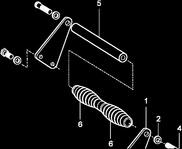
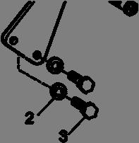
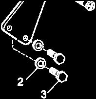
46 FIGURE 12 OUTER PISTON SEAL INSTALLATION FIGURE 13 STANDARD TRANSVERSE CARRYING HANDLE 46
3 X 4 Inch Hydrant Coupler for Digital Pressure Control To Mate Hydrants in Accordance with API Bulletin Model Maintenance Manual SM64802
 SM64802 June 2014 Aerospace Group Conveyance Systems Division Applicable addition manuals: None Carter Ground Fueling Maintenance Manual 3 X 4 Inch Hydrant Coupler for Digital Pressure Control To Mate
Model Maintenance & Repair Manual. 3 x 4 Inch Hydrant Coupler with Pressure Control To Mate Hydrants in Accordance with API Bulletin 1584
 SM64803 June 2014 Aerospace Group Conveyance Systems Division Applicable additional manuals: None Carter Ground Fueling Maintenance & Repair Manual 3 x 4 Inch Hydrant Coupler with Pressure Control To Mate
Model Hydrant Coupler with Pressure Control To Mate Hydrants In Accordance With API Bulletin 1584 SM Maintenance & Repair Manual
 SM64900 April 2011 Applicable addition manuals: None Aerospace Group Conveyance Systems Division Carter Ground Fueling Maintenance & Repair Manual 4 Hydrant Coupler with Pressure Control To Mate Hydrants
SM64155 Maintenance & Repair Manual
 SM64155 September 2011 Applicable addition manuals: Aerospace Group Conveyance Systems Division Carter Brand SM61429 Nozzle SM64349 Nozzle SM64201 Nozzle Maintenance & Repair Manual Continuity Dry Break
SM64052 Maintenance & Repair Manual Commercial 2" Unisex Coupling - Valved Model 64052
 Aerospace Group Conveyance Systems Division Carter Brand Ground Fueling Equipment SM64052 July 2004 Applicable additional manuals: SM64051 Commercial 2" Unisex Coupling, Non-Valved Maintenance & Repair
Models & Inch & 4 Inch Digital Inline Pressure Control Valves SM64504
 SM64504 September 2008 Aerospace Group Conveyance Systems Division Carter Brand Ground Fueling Equipment Applicable addition manuals: None Maintenance & Repair Manual 3 Inch & 4 Inch Digital Inline Pressure
3 Inch & 4 Inch Digital Bypass Pressure Control Valves
 SM64505 September 2008 Aerospace Group Conveyance Systems Division Carter Brand Ground Fueling Applicable addition manuals: None Maintenance & Repair Manual 3 Inch & 4 Inch Digital Bypass Pressure Control
Maintenance & Repair Manual
 SM64055 November 2012 Aerospace Group Conveyance Systems Division Applicable additional manuals: None Carter Brand Ground Fueling Equipment Maintenance & Repair Manual 4 Inch Internal/Bottom Loading Valves
3 Inch & 4 Inch Fuel Operated Bypass Pressure Control Valves. Models & 64513
 SM64503 September 2008 Aerospace Group Conveyance Systems Division Carter Brand Ground Fueling Equipment Applicable addition manuals: None Maintenance & Repair Manual 3 Inch & 4 Inch Fuel Operated Bypass
Models & & 4 Air Operated Bypass Pressure Control Valves SM64501
 SM64501 September 2008 Aerospace Group Conveyance Systems Division Carter Brand Ground Fueling Equipment Applicable addition manuals: None Maintenance & Repair Manual 3 & 4 Air Operated Bypass Pressure
Non-Valved Unisex Coupling
 SM64019 October 2010 Aerospace Group Conveyance Systems Division Applicable additional manuals: None Carter Brand Ground Fueling Equipment Maintenance Manual Non-Valved Unisex Coupling Model 64019 Model
Maintenance Manual. Dry Break Quick Disconnect (Old Style) Model SM November 1, 2011 Applicable additional manuals: SM60427 Nozzle
 Model SM November 1, 2011 Applicable additional manuals: SM60427 Nozzle") Aerospace Group Conveyance Systems Division Carter Brand Ground Fueling Equipment SM60672-1 November 1, 2011 Applicable additional manuals: SM60427 Nozzle Maintenance Manual Dry Break Quick Disconnect
Aerospace Group Conveyance Systems Division Carter Brand Ground Fueling Equipment SM60672-1 November 1, 2011 Applicable additional manuals: SM60427 Nozzle Maintenance Manual Dry Break Quick Disconnect
Model Maintenance Manual SM July 2011
 SM61154 July 2011 Aerospace Group Conveyance Systems Division Carter Brand Ground Fueling Applicable addition manuals: SM61428 Nozzle SM60427 Nozzle SM64348 Nozzle SM64349 Nozzle SM64200 Nozzle SM64201
Model INTERNAL/BOTTOM LOADING VALVES SM Maintenance & Repair Manual. July Applicable addition manuals: None
 SM64128 July 2010 Eaton Aerospace Group Conveyance Systems Division Carter Brand Ground Fueling Equipment Applicable addition manuals: None Maintenance & Repair Manual 6 INTERNAL/BOTTOM LOADING VALVES
Maintenance Manual. Hydrant Coupler. F250 Series
 Hydrant Coupler F250 Series LIST OF EFFECTIVE PAGES On a revised page, the portion of text or illustrations affected by the change is indicated by a vertical line in the outer margin of the page. When
Bottom Loading & Recirculation Adapters
 SM60373 January 2002 Aerospace Group Conveyance Systems Division Carter Brand Ground Fuelin Equipment Applicable additional manuals: None Maintenance Manual Bottom Loading & Recirculation Adapters Models
Quick Disconnect To Mate Nozzle. Model SM40679 August Applicable additional manuals: SM60427 Nozzle SM Hose End Regulator
 SM40679 August 2009 Aerospace Group Conveyance Systems Division Carter Brand Ground Fueling Equipment Applicable additional manuals: SM60427 Nozzle SM60129-1 Hose End Regulator Maintenance Manual Quick
Maintenance Manual. 3-Inch Internal Valve. F660 Series
 3-Inch Internal Valve F660 Series LIST OF EFFECTIVE PAGES On a revised page, the portion of text or illustrations affected by the change is indicated by a vertical line in the outer margin of the page.
Maintenance Manual 3-INCH INTERNAL VALVE F660 SERIES
 Maintenance Manual 3-INCH INTERNAL VALVE F660 SERIES REVISION 1.1 03/15/2002 LIST OF EFFECTIVE PAGES On a revised page, the portion of text or illustrations affected by the change is indicated by a vertical
Model Maintenance Manual. SM44646 October Applicable additional manuals:
 SM44646 October 2009 Aerospace Group Conveyance Systems Division Carter Brand Ground Fueling Equipment Applicable additional manuals: SM61428 NOZZLE SM61429 NOZZLE SM64200 NOZZLE SM64201 NOZZLE SM64348
Maintenance Manual 6-INCH INTERNAL VALVE F620 SERIES
 Maintenance Manual 6-INCH INTERNAL VALVE F620 SERIES REVISION 1.1 03/15/2002 LIST OF EFFECTIVE PAGES On a revised page, the portion of text or illustrations affected by the change is indicated by a vertical
Maintenance Manual 4½-INCH INTERNAL VALVE F635 SERIES
 Maintenance Manual 4½-INCH INTERNAL VALVE F635 SERIES REVISION 1.0 11/01/2004 LIST OF EFFECTIVE PAGES On a revised page, the portion of text or illustrations affected by the change is indicated by a vertical
Maintenance Manual. 4-Inch Internal Valve. F614 Series
 4-Inch Internal Valve F614 Series LIST OF EFFECTIVE PAGES On a revised page, the portion of text or illustrations affected by the change is indicated by a vertical line in the outer margin of the page.
Fisher 657 Diaphragm Actuator Sizes and 87
 Instruction Manual 657 Actuator (30-70 and 87) Fisher 657 Diaphragm Actuator Sizes 30 70 and 87 Contents Introduction... 1 Scope of Manual... 1 Description... 2 Specifications... 2 Installation... 3 Mounting
351GF-15. Hydrant Coupler INSTALLATION / OPERATION / MAINTENANCE MODEL
 INSTALLATION / OPERATION / MAINTENANCE MODEL 351GF-15 Hydrant Coupler 351GF-15 Hydrant Coupler This installation/operation/maintenance guide is designed to provide instructions for the installation operation
GH-BETTIS SERVICE INSTRUCTIONS DISASSEMBLY & REASSEMBLY FOR MODELS HD521-M4, HD721-M4 AND HD731-M4 DOUBLE ACTING SERIES PNEUMATIC ACTUATORS
 GH-BETTIS SERVICE INSTRUCTIONS DISASSEMBLY & REASSEMBLY FOR MODELS HD521-M4, HD721-M4 AND HD731-M4 DOUBLE ACTING SERIES PNEUMATIC ACTUATORS WITH HYDRAULIC CONTROL PACKAGE PART NUMBER: SE-023 REVISION:
SM Pressure Fueling Nozzle Standard Commercial Unit. Model Maintenance Manual
 Eaton Aerospace Business Conveyance Systems Division Carter Ground Fueling Maintenance Manual SM64200 February 2007 APPLICABLE ADDITIONAL MANUALS: SM44315 Quick Disconnect Assy SM44646 Hose End Control
45 VALVE SERIES. 2-Position 4-Way 5-Ports, Installation & Service Instructions. Valve with Stem Operator, Installation & Service Instructions
 (02/20/8) Pneumatic Division Richland, Michigan USA www.parker.com/pneumatics Document Number V275CP V280CP V284CP V32CP 45 VALVE SERIES Description 3-Position 4-Way 5-Ports, Installation & Service Instructions
Inline Pressure Control Or Shutoff Valves (Non-digital) And Bypass Pressure Control Or Shutoff Valves (Non-digital)
 And Bypass Pressure Control Or Shutoff Valves (Non-digital)") IN64124 August 15, 1997 Aerospace Group Conveyance Systems Divison Carter Brand Ground Fueling Equipment Applicable additional manuals: Installation Instructions Inline Pressure Control Or Shutoff Valves
IN64124 August 15, 1997 Aerospace Group Conveyance Systems Divison Carter Brand Ground Fueling Equipment Applicable additional manuals: Installation Instructions Inline Pressure Control Or Shutoff Valves
Swivel Quick Disconnect To Mate Various Carter Brand Nozzles. Model SM Maintenance & Repair Manual
 Aerospace Group Conveyance Systems Division Carter Brand Ground Fueling Equipment SM44315 February 1998 Applicable additional manuals: SM61428 Nozzle SM64348 Nozzle SM64200 Nozzle Maintenance & Repair
Installation, Operation & Maintenance Manual for Flo-Max II Coupler Model FM126
 Installation, Operation & Maintenance Manual for Flo-Max II Coupler Model FM126 December 2015 Form FVC 073 - Rev 09 IMPORTANT: KEEP THIS DOCUMENT WITH THE PRODUCT UNTIL IT REACHES THE END USER. 1. Contact
Digital III Fueling Vehicle Control System
 SM64335-2 April 2005 Aerospace Group Conveyance Systems Division Carter Brand Ground Fueling Equipment Applicable additional manuals: SM64335-1 Setup & Calibration User s Manual Digital III Fueling Vehicle
ONYX VALVE CO MODEL CAR, CAP-PFO Installation & Maintenance
 ONYX VALVE CO MODEL CAR, CAP-PFO Installation & Maintenance OPERATION: (4-2010) The Onyx series CAR-PFO and CAP-PFO pinch valves fail open on loss of air. The simple spring and air bag arrangement drives
GH-BETTIS OPERATING & MAINTENANCE INSTRUCTIONS DISASSEMBLY & ASSEMBLY FOR THE T80X-M4-S DOUBLE ACTING SERIES HYDRAULIC ACTUATORS
 GH-BETTIS OPERATING & MAINTENANCE INSTRUCTIONS DISASSEMBLY & ASSEMBLY FOR THE T80X-M4-S DOUBLE ACTING SERIES HYDRAULIC ACTUATORS -S INDICATES CYLINDERS ARE IN TANDEM PART NUMBER: 100121 REVISION "A" ECN
4000SS. For other repair kits and service parts, send for Ames Repair Parts Price List, PL-A-RP-BPD.
 Series 4000SS RP/IS-A-4000SS 4000SS Reduced Pressure Zone Assemblies Sizes: 8" 10" (200 250mm) Installation Service Repair Kits Maintenance For other repair kits and service parts, send for Ames Repair
OPERATION AND MAINTENANCE MANUAL
 WREN IBT SERIES HYDRAULIC TORQUE WRENCHES IBT SQUARE DRIVE SERIES OPERATION AND MAINTENANCE MANUAL FOR WREN Products: POINT 75, 1IBT, 3IBT, 5IBT, 8IBT, 10IBT, 20IBT, 25IBT, 35IBT, 50IBT SQUARE DRIVE HYDRAULIC
Installation, Operation & Maintenance Manual for Flo-Max II Coupler Model FM126
 IMPORTANT: The Flo-Max II coupler is designed to disconnect the nurse tank hose from a tool bar before the straight pull force on the hose exceeds 450 pounds. Upon disconnect, swing checks in both halves
CAB TILT HYDRAULIC SYSTEM
 OPERATION, MAINTENANCE and SERVICE INSTRUCTIONS CAB TILT HYDRAULIC SYSTEM WITH POWER-PACKER PUMP, CYLINDERS and LATCHES A division of Actuant Corporation 1-800-745-4142 1 www.powerpackerus.com Notice The
I & M 8000 Series. Ideal Installation Schematic. Preferred Installation. Trouble Shooting
 I & M 8000 Series 3170 Wasson Road Cincinnati, OH 45209 USA Phone 513-533-5600 Fax 513-871-0105 lowflow@richardsind.com www.lowflowvalve.com Installation & Maintenance Instructions for 8000 Series Low
ONYX VALVE CO MODEL DAC-PFO Installation & Maintenance
 ONYX VALVE CO MODEL DAC-PFO Installation & Maintenance OPERATION: (01-10) The Onyx series DAC-PFO pinch valve fails open on loss of air. This simple spring and air bag arrangement that drives a pair of
INSTALLATION, OPERATION, MAINTENANCE MANUAL FOR MANUALLY OPERATED STOP CHECK VALVE
 INSTALLATION, OPERATION, MAINTENANCE MANUAL FOR MANUALLY OPERATED STOP CHECK VALVE Page 1 of 13 1.1 General CHAPTER 1 - GENERAL INFORMATION This manual contains maintenance instructions with pertinent
Installation Manual For ISL98, ISL03, ISL07, ISC07
 Installation Manual For ISL98, ISL03, ISL07, ISC07 Table of Contents Section 1: Introduction... 3 Housing Identification... 3 Engine Identification... 3 Special Tools... 3 Automatic Transmissions... 3
Click Here for Printable PDF File. CHAPTER 3 - BASIC INFORMATION for PERFORMING HYDRAULIC SYSTEM MAINTENANCE
 HWH Online Technical School Lesson 1: Introduction to Hydraulics Chapter 3 - "BASIC INFORMATION for PERFORMING HYDRAULIC SYSTEM MAINTENANCE" (Filename: ML57000-012-CH3.DOC Revised: 22APR16) Click Here
MAINTENANCE MANUAL FOR THERMOSTATIC TEMPERATURE REGULATING VALVE TRAC STYLE P
 MANUAL NUMBER P-EFS-1 MAINTENANCE MANUAL FOR THERMOSTATIC TEMPERATURE REGULATING VALVE TRAC STYLE P TRAC Regulator Company Inc. 160 South Terrace Avenue Mount Vernon, New York USA 10550-2408 Phone: (914)
Hydrant Valve In Accordance With Bulletin API Model SM Maintenance & Repair Manual. January 2011
 SM60554 January 2011 Aerospace Group Conveyance Systems Division Applicable addition manuals: SM47076 Carter Brand Ground Fueling Maintenance & Repair Manual Hydrant Valve In Accordance With Bulletin API
Ideal Installation. I & M Mark 67 (1/2 6 ) Control Line. Installation & Maintenance Instructions for Mark 67 Pressure Regulators
 Control Line. Installation & Maintenance Instructions for Mark 67 Pressure Regulators") I & M Mark (/ ) 0 Wasson Road Cincinnati, OH 0 USA Phone --00 Fax -8-00 info@richardsind.com www.jordanvalve.com Installation & Maintenance Instructions for Mark Pressure Regulators Warning: Jordan Valve
I & M Mark (/ ) 0 Wasson Road Cincinnati, OH 0 USA Phone --00 Fax -8-00 info@richardsind.com www.jordanvalve.com Installation & Maintenance Instructions for Mark Pressure Regulators Warning: Jordan Valve
Unisex Couplings, Valved. Model Model SM October Applicable additional manuals: None. Maintenance Manual
 SM64020 October 2010 Aerospace Group Conveyance Systems Division Carter Brand Ground Fueling Equipment Applicable additional manuals: None Maintenance Manual Unisex Couplings, Valved Model 64020 Model
Maintenance Manual WATER SUMP CONTROL VALVE F532B
 WATER SUMP CONTROL VALVE F532B LIST OF EFFECTIVE PAGES On a revised page, the portion of text or illustrations affected by the change is indicated by a vertical line in the outer margin of the page. When
1/2" AIR DRIVEN DIAPHRAGM PUMP
 1/2" DRIVEN DIAPHRAGM PUMP OPERATION AND SERVICE GUIDE O-1225D NOV. 2008 Page 1 of 6 Refer to Bulletin P-605, Parts List P-9151 DRIVEN, DOUBLE DIAPHRAGM PUMP MANUAL Congratulations on purchasing one of
INSTALLATION, OPERATION AND MAINTENANCE MANUAL (IOM)
") INSTALLATION, OPERATION AND MAINTENANCE MANUAL (IOM) IOM-1088 03-16 Model 1088 Vacu-Gard Blanketing Valve ISO Registered Company SECTION I I. DESCRIPTION AND SCOPE The Model 1088 Vacu-Gard is a tank blanketing
INSTALLATION, OPERATION AND MAINTENANCE MANUAL (IOM) IOM-1088 03-16 Model 1088 Vacu-Gard Blanketing Valve ISO Registered Company SECTION I I. DESCRIPTION AND SCOPE The Model 1088 Vacu-Gard is a tank blanketing
Type 657 Diaphragm Actuator Sizes and 87
 Instruction Manual Form 1900 January 2000 Type 657-70 & 87 Type 657 Diaphragm Actuator Sizes 30-70 and 87 Contents Introduction............................... 1 Scope of Manual.............................
Purging Air From Divider Block Lubrication Systems
 FROST ENGINEERING SERVICE Purging Air From Lubrication Systems A D I V I S I O N O F G E C S E Y S A L E S & S E R V I C E DESCRIPTION Divider block lubrication systems operate correctly only when all
IMPORTANT!!!! Read this manual before attempting any installation, wiring or operation.
 Industrial Turbo Meters Sizes 2" through 6" Installation & Operation Manual IMPORTANT!!!! Read this manual before attempting any installation, wiring or operation. BadgerMeter,Inc. IOM-003-15 Part No.
Operation & Service Manual
 Operation & Service Manual Model: 02-1248-0112 12 Ton Single Stage Jack 11/2004 Rev. 02 Includes Illustrated Parts Lists 1740 Eber Rd Tronair, Inc. Phone: (419) 866-6301 Holland, OH 43528-9794 www.tronair.com
 Operation and Maintenance Manual http://www.torsionx.eu Use the MaxDrv Series Square Drive Torque Wrench Model.75, 1, 3, 5, 8, 10, 20, 25, 35, 50 to install and remove threaded fasteners requiring precise
IBT Series Square Drive Torque Wrenches
 IBT Series Square Drive Torque Wrenches Operation and Maintenance Manual Model.75, 1, 3, 5, 8, 10, 20, 25, 35, 50 http://www.torsionx.com Use the IBT Series Square Drive Torque Wrenches Model.75, 1, 3,
Valtek Auxiliary Handwheels and Limit Stops
 Valtek Auxiliary s and Limit Stops Table of Contents Page 1 General information 2 Installation 2 Side-mounted handwheels, size 25 and 50 (linear actuators) 3 Side-mounted handwheels, size 100 and 200 (linear
Model No. 668D3. COFFEPUMP Part No Product Code: O/C GJAN21.DB6B-DC310B
 Model No. 668D3 COFFEPUMP Part No. 9168 Product Code: O/C GJAN21.DB6B-DC310B OVERHAUL MANUAL with ILLUSTRATED PARTS LIST Page 1 of 15 P/N 5914 Rev D 01/17/05 1.0 Introduction 1.1 Description 1.1.1 The
Heavy Duty Miniature Quick-Change Applicator (End-Feed Type) with Mechanical or Air-Feed Systems
 with Mechanical or Air-Feed Systems") Heavy Duty Miniature Quick-Change Applicator (End-Feed Type) with Mechanical or Air-Feed Systems Instruction Sheet 408-8039 02 JUN 16 Rev G Ram Post Wire Disc Insulation Disc Insulation Crimper Stripper
Heavy Duty Miniature Quick-Change Applicator (End-Feed Type) with Mechanical or Air-Feed Systems Instruction Sheet 408-8039 02 JUN 16 Rev G Ram Post Wire Disc Insulation Disc Insulation Crimper Stripper
ONYX VALVE CO MODEL DAO-PFC Installation & Maintenance
 ONYX VALVE CO MODEL DAO-PFC Installation & Maintenance OPERATION: (4-2010) The Onyx DAO-PFC pinch valve is an open frame valve without housing enclosure and fails closed on loss of air. The actuator drives
Maintenance Information
 80234313 Edition 1 June 2006 Air Grinder, Die Grinder, Sander and Belt Sander Series G1 (Angle) Maintenance Information Save These Instructions WARNING Always wear eye protection when operating or performing
Principals of Operation... 1 Rotary Vane Priming Pump VPE and VPES... 2 Rotary Vane Priming Pump VPO and VPOS Priming Valve...
 Priming Systems Installation Priming Systems Operation & Maintenance Form No. F 1031 Section 2312 Issue Date 10/07/94 Rev. Date 02/27/06 Table of Contents Illustrations Principals of Operation...........................
Vane Pumps. Single Stage Single and Double Vane Pumps. Vickers. Overhaul Manual
 Vickers Vane Pumps Overhaul Manual Single Stage Single and Double Vane Pumps V14, 124, 134,144 V19, 129, 139, 149 V15, 125, 135, 145 V35*, 36*, 45*, 46* V18, 128, 138, 148 (V)VF-**-**, (V)VG-**-** Reprinted
Installation, Operation & Maintenance Manual for Flo-Max Couplers Model FM
 (24) 357-459 INCORPORATED (800) 345-805 DALLAS TEXAS Installation, Operation & Maintenance Manual for Flo-Max Couplers Model FM.25-000 February 2008 Form FVC 062 - Rev 08 KEEP THIS DOCUMENT WITH THE PRODUCT
LESSON 2 BASIC CONSTRUCTION AND OPERATION OF HYDRAULIC ACTUATING DEVICES, FLOW CONTROL, AND DIRECTIONAL DEVICES. STP Tasks:
 LESSON 2 BASIC CONSTRUCTION AND OPERATION OF HYDRAULIC ACTUATING DEVICES, FLOW CONTROL, AND DIRECTIONAL DEVICES STP Tasks: 552-758-1003 552-758-1071 OVERVIEW LESSON DESCRIPTION: In this lesson you will
REPAIR PROCEDURES MANUAL
 REPAIR PROCEDURES MANUAL PVX Series Vane Pumps A Design Series Step-by-Step Guide to Troubleshooting and Repairing PVX Series Vane Pumps Introduction Thank you for choosing Continental Hydraulics PVX Vane
ONYX VALVE CO MODEL DAO-ADA Installation & Maintenance
 ONYX VALVE CO MODEL DAO-ADA Installation & Maintenance OPERATION: (4-2010) The Onyx DAO-ADA pinch valve is an open frame valve without housing enclosure and fails last position on loss of air. This actuator
7 Emergency Breakaway Fuel Coupling
 SM64191 August 2011 Applicable additional manuals: None Aerospace Group Conveyance Systems Division Carter Ground Fueling Maintenance & Repair Manual 7 Emergency Breakaway Fuel Coupling Model 64191 Table
THIS WARRANTY IS IN LIEU
 Installation, Operation, Maintenance and Parts Manual for Backflow Prevention Assemblies Double Check Valve Assembly Series 2000DCA 4" 10" Double Check Detector Assembly Series 3000DCDC 4" 10" Reduced
Maintenance & Repair Manual. Misc. Male Adapters To Mate Model Nozzles And Model Couplers. SM427MISC June 1, 1993
 SM427MISC June 1, 1993 Aerospace Group Conveyance Systems Divison Carter Brand Ground Fueling Equipment Applicable addition manuals: SM60427 Nozzle SM61445 Coupler SM40679 Quick Disconnect Maintenance
Vickers. Overhaul Manual. Vane Pumps. Small and Large Series Combination Pumps VC(K)(S)-**-(*)*D*-6(1) VC(K)(S)-**-(*)-*-*D*-5(1)
(S)-**-(*)*D*-6(1) VC(K)(S)-**-(*)-*-*D*-5(1)") Overhaul Manual Vickers Vane Pumps Small and Large Series Combination Pumps VC(K)(S)-**-(*)*D*-6(1) VC(K)(S)-**-(*)-*-*D*-5(1) Revised 12/1/86 I-3150-S Table of Contents Section I. Introduction................................................................................
Overhaul Manual Vickers Vane Pumps Small and Large Series Combination Pumps VC(K)(S)-**-(*)*D*-6(1) VC(K)(S)-**-(*)-*-*D*-5(1) Revised 12/1/86 I-3150-S Table of Contents Section I. Introduction................................................................................
TWO-STAGE HYDRAULIC PUMP. RWP55-IBT-Air
 ORIGINAL INSTRUCTIONS Form No.1000458 5 SPX Corporation 5885 11th Street Rockford, IL 61109-3699 USA Tech. Services: (800) 477-8326 Fax: (800) 765-8326 Order Entry: (800) 541-1418 Fax: (800) 288-7031 Internet
LEAK TEST PROCEDURE APPLICABLE TO DC3 INTELLI-GRIP LIFTERS MODELS MRT4-DC3, MRTA8-DC3, MRTALP8-DC3 AND PC/P1-DC3 SERIES
 LEAK TEST PROCEDURE APPLICABLE TO DC3 INTELLI-GRIP LIFTERS MODELS MRT4-DC3, MRTA8-DC3, MRTALP8-DC3 AND PC/P1-DC3 SERIES TESTING AND MAINTENANCE MUST BE DONE BY A QUALIFIED PERSON KEEP FOR FUTURE REFERENCE
Char-Lynn Hydraulic Motor. Repair Information Series. April, 1997
 Char-Lynn Hydraulic Motor April, 1997 Repair Information Geroler Motors 002 00 004 Parts Drawing 1 See Note 2 Page 1 22 1 9 1-1/4 Split Flange Ports 8 7 6 5 B 1 See Note 2 Page 2 24 4 14 19 20 15 1 18
Maintenance Information
 16573347 Edition 2 February 2014 Air Grinder Series 88H Maintenance Information Save These Instructions Product Safety Information WARNING Failure to observe the following warnings, and to avoid these
 Operation and Maintenance Manual Model.75,, 3, 5, 8, 0, 0, 5, 35, 50 http://www.torsionx.com Use the MaxDrv Series Square Drive Torque Wrench Model.75,, 3, 5, 8, 0, 0, 5, 35, 50 to install and remove threaded
ANDERSON GREENWOOD SERIES 500 PILOT OPERATED SAFETY RELIEF VALVES INSTALLATION AND MAINTENANCE INSTRUCTIONS
 Before installation these instructions must be fully read and understood TABLE OF CONTENTS 1. General valve description and start-up... 1 2. Main valve maintenance... 1 3. Pilot maintenance... 5 4. Pilot
SD Bendix E-12 & E-15 Dual Brake Valve DESCRIPTION
 SD-03-6 Bendix E- & E-15 Dual Brake Valve TREADLE UPPER BODY ASSEMBLY PRIMARY DELIVERY ( ) 1 SECONDARY DELIVERY ( ) LOWER BODY ASSEMBLY MOUNTING PLATE PRIMARY SUPPLY ( SUP-1) PRIMARY SUPPLY ( SUP-) PRIMARY
HexPro Series Low Profile Wrenches
 HexPro Series Low Profile Wrenches Operation and Maintenance Manual Model 2HP 4HP 8HP 14HP 30HP www.torquetoolsinc.com Use the HEXPRO Series Low Profile Wrenches Model 2HP 4HP 8HP 14HP 30HP to install
AUTOMATIC TRANSMISSIONS Mitsubishi F3A20 Series TRANSMISSION APPLICATION TABLE
 Article Text ARTICLE BEGINNING AUTOMATIC TRANSMISSIONS Mitsubishi F3A20 Series APPLICATION TRANSMISSION APPLICATION TABLE Vehicle Application Transmission Model Colt 3-Speed (1990-94)... F3A21 Colt Vista
Maintenance Manual HYDRANT SHUTOFF VALVE F352 / F353 SERIES
 Maintenance Manual HYDRANT SHUTOFF VALVE F352 / F353 SERIES NOTICE: PROPRIETARY INFORMATION OF WHITTAKER CONTROLS, INC., A BUSINESS UNIT OF MEGGITT PLC. THE INFORMATION CONTAINED IN THIS DOCUMENT IS DISCLOSED
Industrial Turbo Meters, Sizes 2" through 6"
 Industrial Turbo Meters Sizes 2" through 6" TUR-UM-00530-EN-19 (October 2014) User Manual Industrial Turbo Meters, Sizes 2" through 6" User Manual CONTENTS Scope of the Manual 5 Specifications 5 Product
HFB Steering Gear Service Manual
 TRW Automotive Commercial Steering Systems HFB Steering Gear Service Manual HFB64 SERIES Die Cut HFB64 Integral Hydraulic Power Steering Gear This steering gear was specifically designed for motor trucks;
SECTION 4 - FUEL SYSTEMS AND CARBURETION
 SECTION - FUEL SYSTEMS AND CARBURETION FUEL SYSTEMS - - - - - - - - - - - - - - - - - - - - - - - - - - - - - - - - - - - - - - - - - - - - - - - - - - - - - - - - - - - - - -62 FUEL PUMP - - - - - - -
COYOTE ENTERPRISES, INC. 9/10 BLAST WHEEL MAINTENANCE & ASSEMBLY MANUAL
 COYOTE ENTERPRISES, INC. 9/10 BLAST WHEEL MAINTENANCE & ASSEMBLY MANUAL Parts & Machinery for the Abrasive Blast Industry 27301 East 121st Street Coweta, Oklahoma 74429 (918) 486-8411 Fax (918) 486-8412
TILLOTSON LTD., CLASH INDUSTRIAL ESTATE, TRALEE, CO. KERRY, IRELAND PHONE: FAX:
 TILLOTSON LTD., CLASH INDUSTRIAL ESTATE, TRALEE, CO. KERRY, IRELAND PHONE: +353 66 7121911 FAX: +353 66 7124503 e-mail: sales@tillotson.ie HR SERIES SERVICE MANUAL INTRODUCTION Tillotson has developed
Maintenance Information
 04581245 Edition 2 May 2014 Air Grinder, Die Grinder and Sander Series G2 (Angle) Maintenance Information Save These Instructions Product Safety Information WARNING Failure to observe the following warnings,
Digital II Pressure Control Module. Model IN64235 August Installation Instructions. Applicable addition manuals:
 Aerospace Group Conveyance Systems Division Carter Brand Ground Fueling Equipment IN64235 August 2009 Applicable addition manuals: IN64101 IN64108 IN64102 IN64802 SU64235 Installation Instructions Digital
Colt Series C400, C500
 Colt Series C400, C500 RP/IS-A-C400/C500 C400 OSY Reduced Pressure Zone Assemblies Reduced Pressure Detector Assemblies Sizes: 2 1 2" 10" (65 250mm) Installation Service Repair Kits Maintenance For other
OPERATING INSTRUCTIONS & SERVICE MANUAL BLUE MAX II HYDROSTATIC TEST PUMP
 PAGE 1 OF 10 OPERATING INSTRUCTIONS & SERVICE MANUAL BLUE MAX II HYDROSTATIC TEST PUMP EFFICIENT, EASY OPERATION Air operated pump Wide range of pressures and volumes Easy to operate controls Output pressure
OLYMPIAN MODEL 740 Operation and Service Manual
 OLYMPIAN MODEL 740 Operation and Service Manual P/N 133911-102 FCI MANUAL P/N 133865-001 Data herein has been verified and validated and believed adequate for the intended use. If the machine or procedures
LEAK TEST PROCEDURE MRTALPCH611LDC REMOTE READY LIFTERS W/ 3 BUTTON CONTROL APPLICABLE TO LIFTERS WITH SERIAL NUMBERS GREATER THAN #
 LEAK TEST PROCEDURE MRTALPCH611LDC REMOTE READY LIFTERS W/ 3 BUTTON CONTROL APPLICABLE TO LIFTERS WITH SERIAL NUMBERS GREATER THAN # 20100742 TESTING AND MAINTENANCE MUST BE DONE BY A QUALIFIED PERSON
Low Profile Wrenches Operation and Maintenance Manual
 Low Profile Wrenches Operation and Maintenance Manual http://www.torquetoolsinc.com Use the HEXPRO Series Low Profile Wrenches Model 2HP 4HP 8HP 14HP 30HP to install and remove large bolts that have minimal
AIR/HYDRAULIC INJECTION GUN MODEL INSTRUCTIONS
 I. OPERATION & DESCRIPTION The Air / Hydraulic Injection Gun is a high-pressure tool that should be used with caution and according to these instructions. IMPORTANT: The Gun is 0,000 psi rated. Do not
Miscellaneous Male Adapters To Mate Nozzle Models & 64348
 SM428MISC June 1, 1993 Conveyance Systems Division Aerospace Group Carter Brand Ground Fueling Equipment Applicable addition manuals: SM61428 NOZZLE SM64348 NOZZLE Maintenance & Repair Manual Miscellaneous
I & M Mark 78 Series. Ideal Installation. Start-Up. Installation & Maintenance Instructions for Mark 78 Control Valves (1-1/2-2 )
") I & M Mark 8 Series 0 Wasson Road Cincinnati, OH 4509 USA Phone 5-5-5600 Fax 5-8-005 info@richardsind.com www.jordanvalve.com Installation & Maintenance Instructions for Mark 8 Control Valves (-/ - ) Warning:
I & M Mark 8 Series 0 Wasson Road Cincinnati, OH 4509 USA Phone 5-5-5600 Fax 5-8-005 info@richardsind.com www.jordanvalve.com Installation & Maintenance Instructions for Mark 8 Control Valves (-/ - ) Warning:
1.1 Quad Valve and Tri-Valve. Contents WATER DUMP BODY O-RING EXHAUST VALVE QUAD VALVE TIE WRAP EXHAUST MAIN BODY O-RING
 Quad Valve and Tri-Valve Exhaust Assembly on Fiberglass Helmets Quad Valve and Tri-Valve Exhaust Contents QUAD-1 QUAD-2 QUAD-2 QUAD-2 QUAD-6 QUAD-7 1.1 Quad Valve and Tri- Valve Exhaust Assembly on Fiberglass
Kysor On/Off Rear Air Fan Drive
 . Proper precautions must be taken to prevent personal injury from contact with moving parts, unintended engine start, or other hazards present when working with powered equipment. Refer to the vehicle
INSTALLATION INSTRUCTIONS FOR THE TRUCK MOUNTED VIPER ADDITIVE INJECTION SYSTEM GTP-8776C
 INSTALLATION INSTRUCTIONS FOR THE TRUCK MOUNTED VIPER ADDITIVE INJECTION SYSTEM GTP-8776C This additive injection system was designed to be used with five gallon jug of additive. The system is supplied
Maintenance Information
 16573370 Edition 2 February 2014 Air Grinder 99V Series Maintenance Information Save These Instructions Product Safety Information WARNING Failure to observe the following warnings, and to avoid these