SERVICE MANUAL IMPINGER COUNTERTOP OVEN MODEL 1300 SERIES
|
|
|
- Cassandra Holmes
- 6 years ago
- Views:
Transcription
1 SERVICE MANUAL IMPINGER COUNTERTOP OVEN MODEL 1300 SERIES Lincoln Foodservice Products, LLC 1111 North Hadley Road Fort Wayne, Indiana United States of America Phone : (800) U.S. Fax: (888) Int l Fax: (260) Technical Service Hot Line (800) svcman REV: 1/5/07
2 SERVICE AND PARTS MANUAL 1300 SERIES IMPINGER COUNTERTOP OVEN TABLE OF CONTENTS TABLE OF CONTENTS...2 SEQUENCE OF OPERATIONS...3 SCHEMATIC 1301, 1302 S/N & BELOW...5 SCHEMATIC 1301, 1302 S/N TO SCHEMATIC 1300, 1301, 1302, 1310 S/N TO SCHEMATIC 1300, 1301, 1302, 1310 S/N SCHEMATIC 1300, 1301, , 1302, , 1310 S/N TO SCHEMATIC 1300, 1301, , 1302, , 1310 S/N & ABOVE...10 SCHEMATIC , S/N & BELOW...11 SCHEMATIC , S/N TO SCHEMATIC , S/N & ABOVE...13 SCHEMATIC 1303,1304 S/N & BELOW...14 SCHEMATIC 1303,1304 S/N TO SCHEMATIC 1303,1304 S/N & ABOVE...16 SCHEMATIC S/N & BELOW...17 SCHEMATIC S/N TO SCHEMATIC S/N & ABOVE...19 SCHEMATIC 1305,1306 S/N & BELOW...20 SCHEMATIC 1305,1306 S/N TO SCHEMATIC 1305,1306 S/N & ABOVE...22 SCHEMATIC S/N & BELOW...23 SCHEMATIC S/N TO SCHEMATIC S/N & ABOVE...25 SCHEMATIC 1307 S/N & BELOW...26 SCHEMATIC 1307 S/N TO SCHEMATIC 1307 S/N & ABOVE...28 SCHEMATIC 1308,1309,1311 S/N & BELOW...29 SCHEMATIC 1308,1309,1311 S/N TO SCHEMATIC 1308,1309,1311 S/N & ABOVE...31 SCHEMATIC S/N & BELOW...32 SCHEMATIC S/N TO SCHEMATIC S/N & ABOVE...34 SCHEMATIC E S/N & BELOW...35 SCHEMATIC E S/N & ABOVE...36 SCHEMATIC E S/N & BELOW...37 SCHEMATIC E S/N & ABOVE...38 SCHEMATIC 1314-F24-E S/N & BELOW...39 SCHEMATIC 1314-F24-E S/N & ABOVE...40 TROUBLESHOOTING GUIDE...41 REMOVAL, INSTALLATION, AND ADJUSTMENT...45 CONVEYOR CONTROL BOARD - REPLACEMENT...48 GENERAL 1300 SERIES...54 GENERAL 1300 SERIES PARTS BLOW-UP...55 CONTROL COMPARTMENT 1300 SERIES...56 CONTROL COMPARTMENT 1300 SERIES BLOW - UP...57 BACK 1300 SERIES...58 BACK 1300 SERIES BLOW - UP...59 STANDARD CONVEYOR 1300 SERIES...60 EXTENDED CONVEYOR 1300 SERIES CounterTop 1300 Series Service Manual
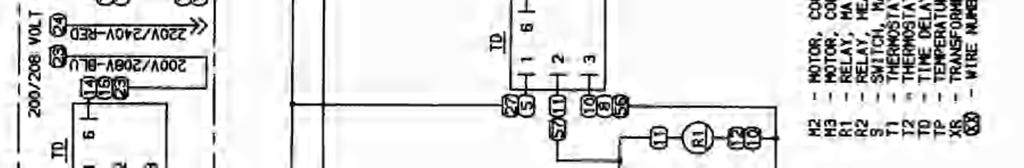
3 SEQUENCE OF OPERATIONS MODEL CTI VAC 60 HZ 1 PHASE VAC 60 HZ1 1 PHASE VAC 60 HZ 1 PHASE VAC 50 HZ 1 PHASE VAC 50 HZ 1 PHASE /220 VAC 50 HZ 1 PHASE /240 VAC 50 HZ 1 PHASE VAC 60 HZ 3 PHASE /220 VAC 50 HZ 3 PHASE /240 VAC 50 HZ 3 PHASE VAC 60 HZ 1 PHASE /220 VAC 60 HZ 3 PHASE E 400/230 VAC 50 HZ 3 PHASE E 400/230 VAC 50 HZ 2 PHASE 1314-F24-E 240 VAC 50 HZ 1 PHASE POWER SUPPLY (Electrical power supplied to the oven:) 1300/1301/ /1304/1314-F24-E 1305/1306 Black Hot Red Hot Green - Ground Brown - Hot Blue Neutral Green/Yellow-Ground Brown Hot Black Hot Blue Neutral Green/Yellow-Ground /1309/ Red Hot Black - Hot Orange Hot Green - Ground E Black (3) Hot Blue Neutral Green/Yellow Ground Brown Hot Black (2) Hot Blue Neutral Green/Yellow Ground E Black (2) Hot Blue Neutral Green/Yellow - Ground Brown Hot Black Hot Green/Yellow-Ground CounterTop 1300 Series Service Manual 3
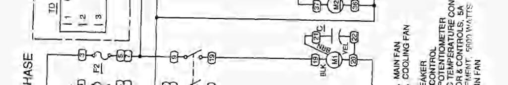
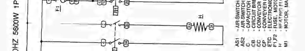
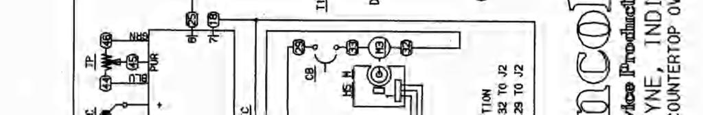
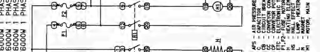
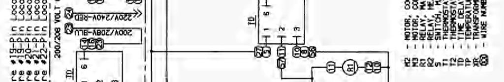
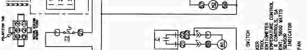
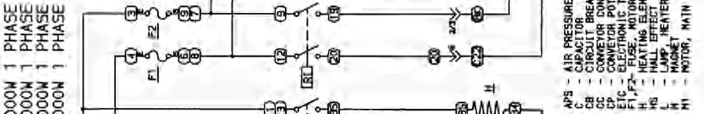
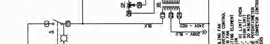
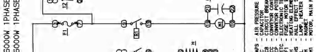
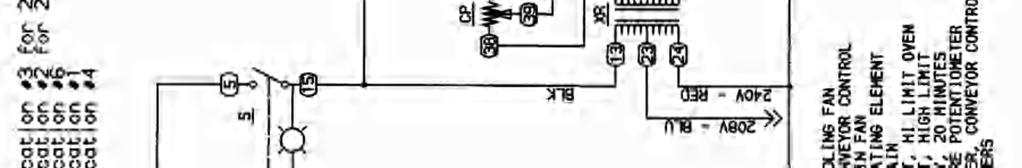
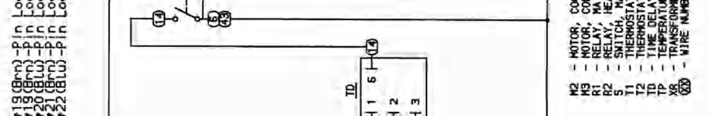
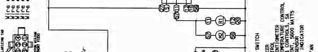
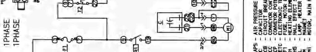
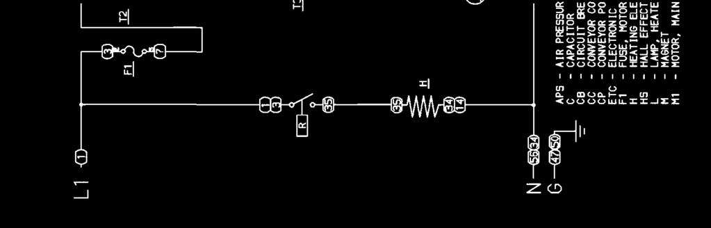
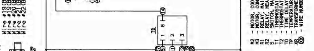
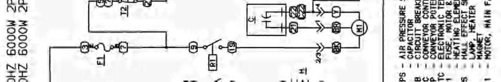
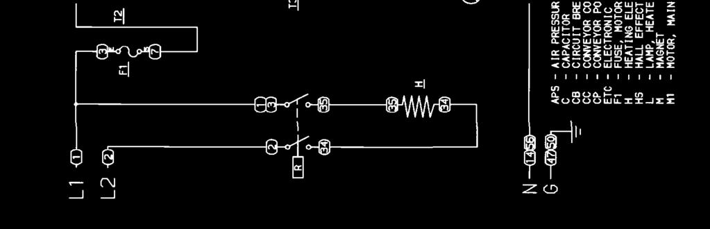
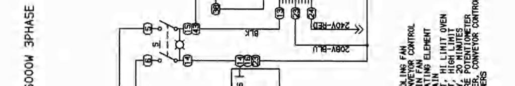
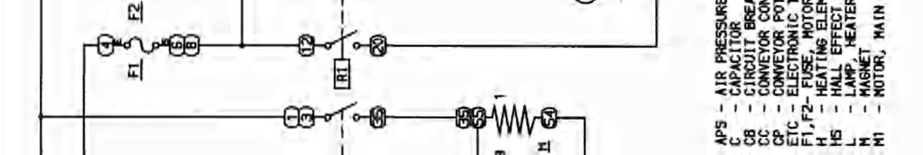
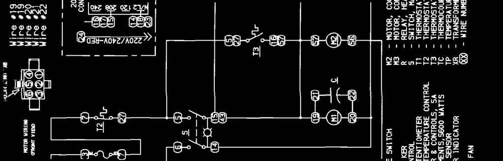
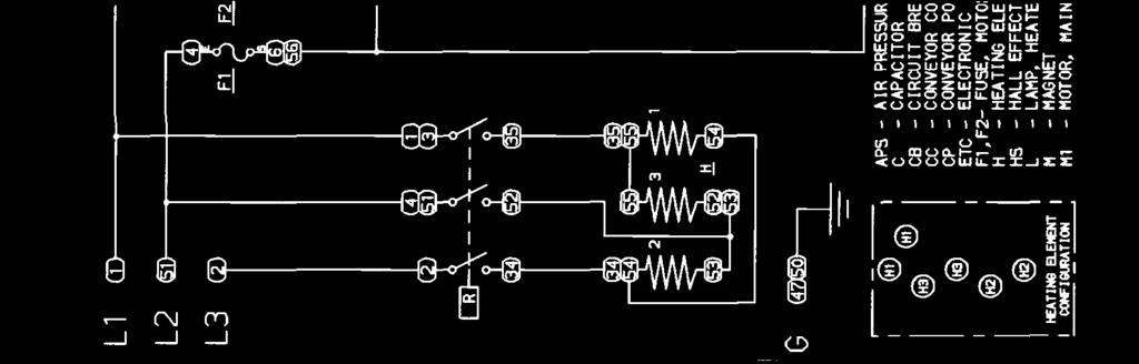
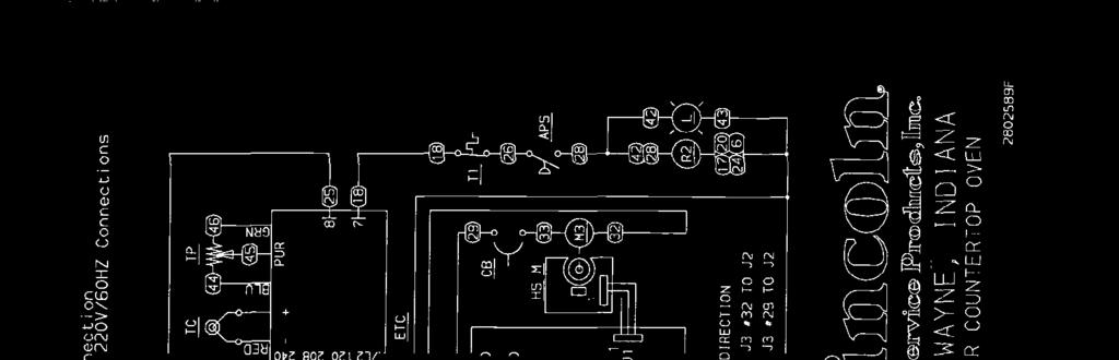
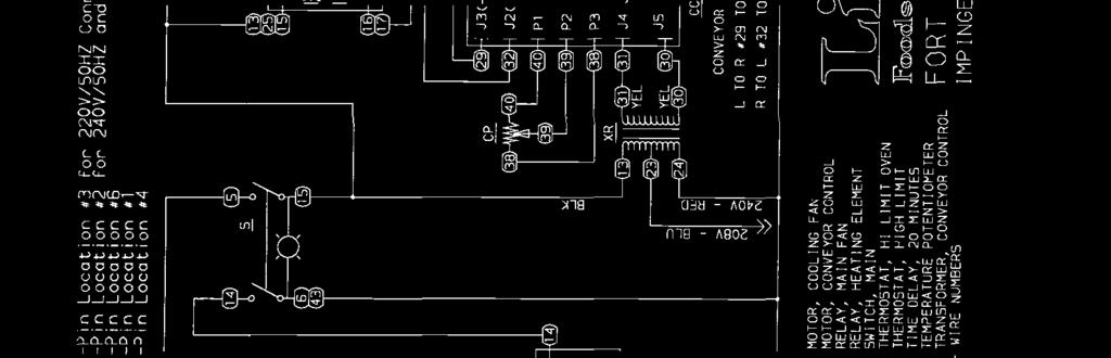
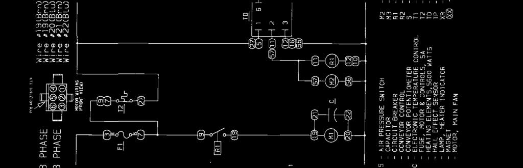
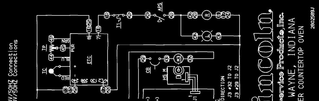
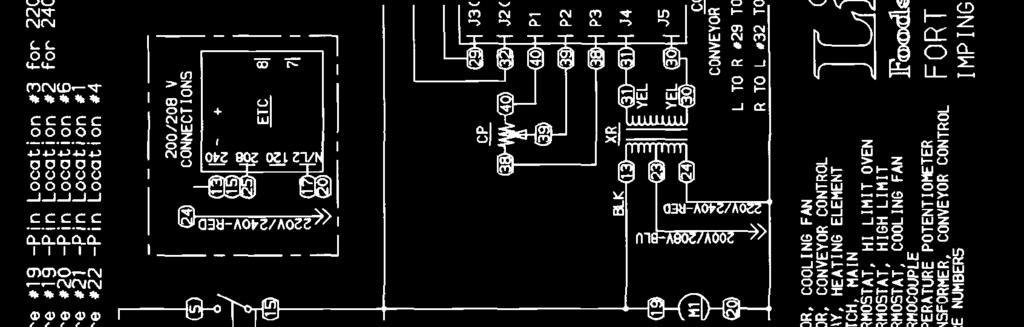
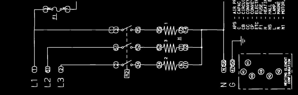
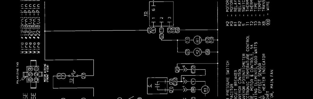
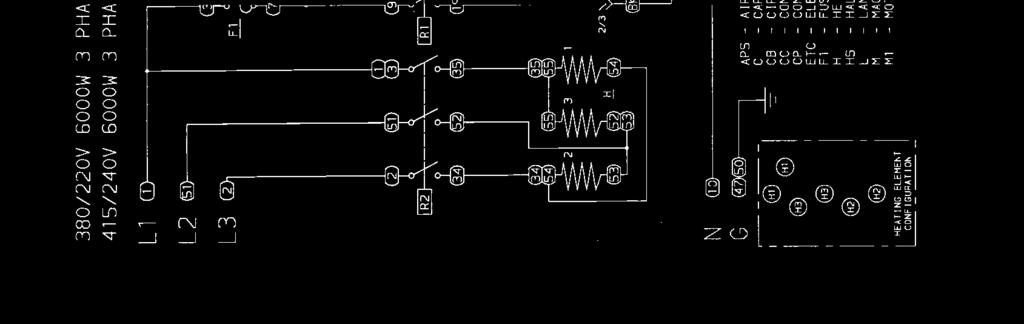
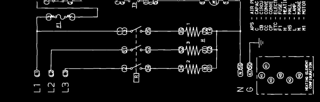
4 MAIN FAN CIRCUIT Electrical power is permanently supplied through the Control Box Hi-Limit to terminal one (1) of the 20- Minute Timer. When the DPST Fan Switch is closed, the timer is enabled. This energizes terminal two (2) of timer, which supplies power to the Coil of the Fan Relay and the Cooling Fan Motor. The normally open contacts of the Fan Relay now close energizing the Main Fan Motor. Closing the Main Fan Switch also supplies power to the Conveyor, Control Transformer, and the Electronic Temperature Control Board. TEMPERATURE CONTROL CIRCUIT Closing the Main Fan Switch supplies power to the Temperature Control Board. The Temperature Control Potentiometer is adjusted to the desired temperature. Power is then supplied through the normally closed High Limit Thermostat and the Main Fan Air Switch to the Coil of heating element relay. When the contacts of the heating element relay are closed, power is then applied to the 5600W Heating Element. The Thermocouple provides varying millivolts to the Temperature Control Board. The temperature control board supplies voltage to the Coil of the heating element relay at intermittent intervals to maintain desired temperature. CONVEYOR DRIVE Closing the Main Fan Switch supplies voltage to the primary of the Transformer, the secondary of the Transformer then supplies 24 VAC to the Conveyor Control Board. AC voltage is converted to DC voltage and is supplied to the Drive Motor at terminals J3(-) and J2(+). Adjustment of the Speed Control Potentiometer will change resistance at terminals P1, P2, and P3 varying the DC voltage to the motor. The speed of the conveyor motor will increase or decrease as the DC voltage from the board increases or decreases respectively. NOTE: The conveyor control uses a sensor and magnet mounted on the conveyor motor that senses the motor speed. Any change in motor load (± RPM) is detected by the sensor and the voltage to the motor is adjusted accordingly. 4 CounterTop 1300 Series Service Manual


5 SCHEMATIC 1301, 1302 S/N & BELOW CounterTop 1300 Series Service Manual 5


6 SCHEMATIC 1301, 1302 S/N TO CounterTop 1300 Series Service Manual


7 SCHEMATIC 1300,1301,1302,1310 S/N TO CounterTop 1300 Series Service Manual 7
8 SCHEMATIC 1300,1301,1302,1310 S/N CounterTop 1300 Series Service Manual
9 SCHEMATIC 1300, 1301, , 1302, , 1310 S/N TO CounterTop 1300 Series Service Manual 9
10 SCHEMATIC 1300, 1301, , 1302, , 1310 S/N & ABOVE 10 CounterTop 1300 Series Service Manual


11 SCHEMATIC , S/N & BELOW CounterTop 1300 Series Service Manual 11


12 SCHEMATIC , S/N TO CounterTop 1300 Series Service Manual
13 SCHEMATIC , S/N & ABOVE CounterTop 1300 Series Service Manual 13


14 SCHEMATIC 1303,1304 S/N & BELOW 14 CounterTop 1300 Series Service Manual


15 SCHEMATIC 1303,1304 S/N TO CounterTop 1300 Series Service Manual 15
16 SCHEMATIC 1303,1304 S/N & ABOVE 16 CounterTop 1300 Series Service Manual


17 SCHEMATIC S/N & BELOW CounterTop 1300 Series Service Manual 17


18 SCHEMATIC S/N TO CounterTop 1300 Series Service Manual
19 SCHEMATIC S/N & ABOVE CounterTop 1300 Series Service Manual 19


20 SCHEMATIC 1305,1306 S/N & BELOW 20 CounterTop 1300 Series Service Manual


21 SCHEMATIC 1305,1306 S/N TO CounterTop 1300 Series Service Manual 21
22 SCHEMATIC 1305,1306 S/N & ABOVE 22 CounterTop 1300 Series Service Manual


23 SCHEMATIC S/N & BELOW CounterTop 1300 Series Service Manual 23


24 SCHEMATIC S/N TO CounterTop 1300 Series Service Manual
25 SCHEMATIC S/N & ABOVE CounterTop 1300 Series Service Manual 25


26 SCHEMATIC 1307 S/N & BELOW 26 CounterTop 1300 Series Service Manual


27 SCHEMATIC 1307 S/N TO CounterTop 1300 Series Service Manual 27
28 SCHEMATIC 1307 S/N & ABOVE 28 CounterTop 1300 Series Service Manual

29 SCHEMATIC 1308,1309,1311 S/N & BELOW CounterTop 1300 Series Service Manual 29

30 SCHEMATIC 1308,1309,1311 S/N TO CounterTop 1300 Series Service Manual
31 SCHEMATIC 1308,1309,1311 S/N & ABOVE CounterTop 1300 Series Service Manual 31


32 SCHEMATIC S/N & BELOW 32 CounterTop 1300 Series Service Manual


33 SCHEMATIC S/N TO CounterTop 1300 Series Service Manual 33
34 SCHEMATIC S/N & ABOVE 34 CounterTop 1300 Series Service Manual


35 SCHEMATIC E S/N & BELOW CounterTop 1300 Series Service Manual 35


36 SCHEMATIC E S/N & ABOVE 36 CounterTop 1300 Series Service Manual


37 SCHEMATIC E S/N & BELOW CounterTop 1300 Series Service Manual 37


38 SCHEMATIC E S/N & ABOVE 38 CounterTop 1300 Series Service Manual


39 SCHEMATIC 1314-F24-E S/N & BELOW CounterTop 1300 Series Service Manual 39


40 SCHEMATIC 1314-F24-E S/N & ABOVE 40 CounterTop 1300 Series Service Manual
41 TROUBLESHOOTING GUIDE IMPINGER CTI SYMPTOM POSSIBLE CAUSE EVALUATION Oven fan will not run Incoming Power Supply Check breakers, reset if required Check power plug to be sure it is firmly in the receptacle (if applicable). Measure the incoming power, call Power Co., if needed Oven Fan Fuses, 5 Amp Check and/or replace Fuse Holder Check and/or replace High Limit Thermostat Control Box (Note: High Limit not used in ovens S/N ) Check for voltage on both sides of the switch. Terminals are normally closed. If open, reset and test oven for proper operation. If thermostat and below.) will not hold and control box temperature is No main fan cool down Main fan continues to run after cool down No control box cooling Fan Switch not exceeding 140 F (60 C), replace thermostat. Check continuity between switch terminals. Check and insure good wire connections 20 Minute Time Delay Check for supply voltage at terminal #1 to ground on the 20-minute timer. If no voltage is present, trace wiring back to power supply. If voltage is present at terminal #1, check for supply voltage at terminal #2 to ground. If no voltage is present, and the oven fan switch is closed, replace the 20-minute timer. Main Fan Relay Fan Motor Capacitor 20-Minute Timer Check continuity of coil. Check for power to relay coil. Visually check for contact pull in and contact condition. Check for voltage across relay terminals. Check for opens, shorts, or grounds. WITH POWER OFF: Turn fan blade to check for locked rotor. Check for opens, shorts, or grounds. WARNING Capacitor has a stored charge, discharge before testing. Check for supply voltage at terminal #2 and #3 while main fan is running. Turn off fan switch and supply voltage should continue to be present for 20 min. at terminal #2. Replace as needed. 20 Minute Timer NOTE: On/Off operation of fan switch will reset timer to 20 minutes. If timer is accidentally reset, turn off main breaker to cancel. If voltage continues to be present at terminals 2 and 3 after 20 minutes, verify fan switch contacts have opened, replace timer as needed. Fan Switch WITH POWER OFF: Close switch and check for continuity across switch terminals. 20 Minute Timer See "Main Fan Motor will not run." Cooling Fan Check for voltages at the fan motor, if present, replace defective fan motor. CounterTop 1300 Series Service Manual 41
42 Oven will not heat Main Oven Fan Temperature Control Board Thermocouple Sensor Temperature Set Potentiometer Hi Limit Thermostat- Oven Cavity Air Pressure Switch (S/N and below) Heating Element Relay Heater Element Check if main oven fan is working. If not, refer to "Oven Fan Will Not Run". Check for voltage input at the board. Turn the temperature adjustment knob to the maximum temperature position and check for voltage at the load terminal. If present, and unit is not heating, refer to "Air pressure switch" for next check. If no voltage is present, proceed. Check terminals, wiring, and proper location of the sensor bulb. It must be in its spring holder located in the inside, rear, lower right hand corner (viewed from front) behind Finger #4. The thermocouple is a type J and has one red lead (Neg.) and one white lead (Pos.).WITH POWER ON AND THERMOCOUPLE LEADS ATTACHED TO THE TEMPERATURE CONTROL BOARD: Measure the D.C. millivolt output of these leads. Refer to thermocouple chart in Section D for proper readings. If these readings are not achieved, replace the thermocouple. Disconnect the potentiometer leads from the board. Place ohm meter test leads on the blue and green pot. leads. Reading should be 1 K ohms. Place meter leads across the blue and purple pot. leads and rotate knob from high to low. Repeat on green and purple leads. Check for even rise and fall of ohms reading to insure that there are no open or dead spots in the potentiometer. Check each lead to ground for shorts. Replace Pot. if it does not meet the above test. Terminals are normally closed, open at 660 F (350 C). If open, push in reset button and retest. If thermostat will not hold for maximum oven temperature, and oven is not exceeding temperature dial setting, check for proper location of capillary bulb in its spring holder. If above checks okay, replace hi-limit thermostat. Check for voltage on both sides of the switch, if voltage is present on one side only, check for air tube blockage, adjust air switch, if above fails, replace switch. Check for voltage to the Relay coil and contacts. If voltage is present and contactor will not activate, replace the contactor. Check for voltage across relay terminals. Check the amperage draw on each hot leg for proper load. Check the rating plate for rating information. If amp draw is low or high, check element for opens and shorts. 42 CounterTop 1300 Series Service Manual
43 Conveyor will not run S/N and Below Conveyor speed varying or intermittent Fan Switch Conveyor Control Transformer Speed Adjustment Potentiometer Conveyor Control Board Conveyor Gear Motor Conveyor Power Supply Transformer Conveyor Control D.C. Gearmotor Check continuity between switch terminals. Replace as needed. Check for supply voltage at primary of transformer. If no voltage is present, trace wiring back to fan switch. Check for 24VAC at transformer secondary. If no voltage is present, replace transformer. This is a 5K ohm potentiometer. WITH POWER OFF: Remove the leads from the motor control board at terminals P1, P2, P3. With a digital meter, check the ohm reading across the red and black leads. This reading should be 5K ohms (± 10%) as the pot. is rotated from low to high. Place meter leads on red and white lead. Rotating the pot. slowly from low to high, the meter reading should show an even transition from 0 to 5K ohms (± 10%). There should be no dead or open spots throughout the rotation of the pot. Check all three (3) leads to ground. There should be no continuity to ground. If any of the above checks fail, replace the pot. Check for 24 VAC input to conveyor control. If no voltage is present, trace wiring back to transformer. If voltage is present at L1 and L2, check for D.C. output at terminals A+ and A-. If there is AC voltage input, but no D.C. voltage output, replace conveyor control board. If there is D.C. voltage output from the conveyor control, but the motor does not run, check the minibreaker (0.7 Amp). Check motor leads for opens, shorts or continuity to ground. If motor fails above test, replace motor. Check conveyor drive coupling to be sure that it is tight. Also check to see that coupling is engaged with conveyor drive shaft. Check for any mechanical misalignment or improper adjustment, also check for worn bearings. A conveyor belt that is too tight will cause excessive bearing wear and sometimesirregular speed. Check for steady supply voltage to oven. If voltage is unsteady, contact power company. Check for steady A.C. voltage output from transformer and replace as needed. Check for steady D.C. voltage output from conveyor control. If D.C. voltage output is unsteady, check conveyor potentiometer (see "Speed Adjustment Potentiometer" under Conveyor will not run). If the potentiometer checks good, and the D.C. voltage is unsteady, replace conveyor control. Check motor brushes for excessive arching and/or unusual wear. Replace brushes or gearmotor as needed. CounterTop 1300 Series Service Manual 43
44 Conveyor will not run (S/N & Above) Conveyor speed varying or intermittent Fan Switch Conveyor Control Transformer Speed Adjustment Pot Conveyor Control Board Conveyor Gear Motor Conveyor Power Supply Transformer Conveyor Control D.C. Gearmotor Magnet Hall Effect Sensor WITH POWER OFF: Check continuity between switch terminals. Check and insure good wire connections. With the fan switch on, check for supply voltage at the primary of the transformer. Check for voltage on the secondary side of transformer (24 VAC) at J4 and J5 on the conveyor control board. Replace as needed. This is a 50 K ohm potentiometer. WITH POWER OFF: Remove the leads from the motor control board at terminals P1, P2, P3. With a digital meter, check the ohm reading across the red and black leads. This reading should be 50K ohms (± 10%) as the pot. is rotated from low to high. Place meter leads on red and white lead. Rotating the pot. slowly from low to high, the meter reading should show an even transition from 0 to 50 K ohms (±10%). There should be no dead or opens spots throughout the rotation of the pot. Check all three (3) leads to ground. There should be no continuity to ground. If any of the above checks fail, replace the pot. Check for 24 VAC input to the control board at terminals J4 and J5. If not present, check wiring back to control transformer, if voltage is present at J4 and J5, check the VDC output at terminals J2 (+) & J3 (-) (0-18 VDC). If 24 VAC is present at J4 and J5, but VDC is not present at J2(+) & J3(-) replace board. If D.C. voltage is present at J2(+) and J3(-) and the motor does not run, first check the mini breaker (.7Amp). Check the leads to the motor for evidence of any shorts or opens, and each lead to ground. If the motor fails the above tests, replace motor. Check for any mechanical misalignment or improper adjustment, also check for worn bearings. A conveyor belt that is too tight will cause excessive bearing wear and sometimes, irregular speed. Check for steady supply voltage to oven. If voltage is unsteady, contact Power Company. Check for steady AC voltage output from transformer and replace as needed. Check for steady D.C. voltage output from conveyor control. If D.C. voltage output is unsteady, check conveyor potentiometer (See Speed Adjustment Potentiometer" under Conveyor will not run). If the potentiometer checks good, and the D.C. voltage is unsteady, replace conveyor control. Check motor brushes for excessive arching and/or unusual wear. Replace brushes or gearmotor as needed Check to insure that the magnet (cemented to shaft of conveyor drive motor) has not been damaged, or come loose from motor shaft. Replace as needed. Check for any physical damage to Hall Effect Sensor (mounted on conveyor motor). Check all wiring and connections or damage. Check all connections for tightness or proper location and check all wiring or visible damage. Replace as needed. 44 CounterTop 1300 Series Service Manual
45 REMOVAL, INSTALLATION, AND ADJUSTMENT SWITCH, ON-OFF MODEL SERIES 1300 CAUTION! BEFORE REMOVING OR INSTALLING ANY COMPONENT IN THE IMPINGER OVEN BE SURE TO DISCONNECT ELECTRICAL POWER SUPPLY 1. Remove conveyor and oven side panels. 2. Remove two (2) screws from ends of control panel and remove panel. 3. Disconnect four (4) wires from switch assembly. Mark wires for reinstallation. 4. Depress clips on side of switch and remove from panel. 5. Reassemble in reverse order and check operation. POTENTIOMETER, CONVEYOR CONTROL 1. Remove conveyor and oven side panels. 2. Remove two (2) screws from ends of control panel and remove panel. 3. Unplug potentiometer at the wire harness (push on connectors). 4. Loosen set screws on control knob and remove knob. 5. Remove retaining nut from potentiometer shaft and remove pot. 6. Reassemble in reverse order and check operation, recalibrate if needed. POTENTIOMETER, TEMPERATURE CONTROL 1. Remove conveyor and oven side panels. 2. Remove two (2) screws from ends of control panel and remove panel. 3. Unplug potentiometer at the wire harness (push on connectors). 4. Loosen set screws on control knob and remove knob. 5. Remove retaining nut from potentiometer shaft and remove pot. 6. Reassemble in reverse order and check operation, recalibrate if needed. CIRCUIT BREAKER, 0.7 AMP 1. Remove control box cover. 2. Remove two (2) wires from mini-breaker. 3. Remove knurled nut and remove breaker. 4. Reassemble in reverse order and check operation. FUSE HOLDER 1. Remove control box cover. 2. Remove two (2) wires from fuse holder. 3. Remove two (2) screws and remove holder. 4. Reassemble in reverse order and check operation. CounterTop 1300 Series Service Manual 45
46 THERMOSTAT, OVEN CAVITY HI-LIMIT 1. Remove control box cover. 2. Remove oven back assembly. (See OVEN BACK) 3. Remove two (2) wires from thermostat. 4. Remove retaining nut from the front of thermostat and remove thermostat. 5. Remove capillary tube from wire form in back of oven and remove assembly out through control box side. 6. Reassemble in reverse order. Check for proper routing through insulation. Be sure capillary tube is held securely in the wire form and the reset button has been pushed in and set. NOTE: All excess capillary tubing should be brought back into control box area. Be certain to replace insulation seal when oven back is re-installed. 7. Check operation. AIR PRESSURE SWITCH REPLACEMENT (S/N and below) 1. Remove control box cover. 2. Remove two (2) wires. 3. Remove air tube (note location). 4. Remove four (4) screws and replace air switch. 5. Reassemble in reverse order and check operation. NOTE: Make sure to use rubber grommets when installing air switch. ADJUSTMENT SCREW AIR PRESSURE SWITCH ADJUSTMENT (S/N and below) 1. Apply power to oven, turn temperature control potentiometer to max. and allow 30-minutes preheat for temperatures to stabilize. 2. Remove air tube and with a volt meter verify that contactor for heater elements opens. 3. WITH POWER ON: Re-connect tube and check voltage across the air switch making sure that there is no voltage drop and it remains steady. Adjust as needed. (See Picture, verify adjustment screw has not vibrated out). NOTE: Allow 30 minutes preheat. THERMOSTAT, CONTROL BOX HI-LIMIT 1. Remove control box cover. 2. Remove two (2) wires. 3. Remove two (2) screws and replace 4. Reassemble in reverse order and check operation. NOTE: Make sure reset button has been pushed and set. 46 CounterTop 1300 Series Service Manual
47 MAIN FAN RELAY 1. Remove control box cover 2. Remove wires from relay and mark wires for reinstallation. 3. Remove two (2) screws and replace relay. 4. Reassemble in reverse order and check operation. TIME DELAY RELAY 1. Remove control box cover. 2. Remove wires from relay and mark wires for reinstallation. CAUTION: Resistor should be jumpered across terminals #2 and #3 on some of the early models (SN and below) this jumper was installed across terminals #1 and #3 which may cause failure of the timer. Correct when replacing timer. 3. Remove screw and replace relay. 4. Reassemble in reverse order and check operation. NOTE: Do not overtighten mounting screw as this could damage timer. RELAY CONTACTOR 1. Remove control box cover. 2. Remove wires and mark wires for reinstallation. 3. Remove four (4) mounting screws and replace contactor. 4. Reassemble in reverse order and check operation. TRANSFORMER - CONVEYOR 1. Remove control box cover. 2. Disconnect wires from primary and secondary of transformer. Mark wires for reinstallation (#23-blue- 208V connection/#24-red-240v connection). NOTE: Wire nut one not being used. 3. Remove two (2) mounting screws and replace. 4. Reassemble in reverse order and check operation. CONVEYOR DRIVE MOTOR 1. Remove conveyor (see Installation and Operations Manual). 2. Remove screw from center of coupling sleeve assemby. and slide coupling assembly off motor shaft. 3. Remove control box cover. 4. Disconnect motor leads and mark wires for reinstallation and conveyor direction. 5. Remove four (4) motor mounting screws and replace motor. 6. Reassemble in reverse order and check operation. NOTE: Check to insure coupling and conveyor shaft are aligned. NOTE: Starting with SN all conveyor drives will be a closed loop system. The drive motor assembly will include a hall effect sensor board and magnet. No calibration required. S/N and Below--Check calibration of conveyor control board (See "Conveyor control board calibration") S/N and Above--Attach correct magnet to conveyor motor assembly. CounterTop 1300 Series Service Manual 47
48 ASSEMBLY OF MAGNET TO MOTOR FOR OVENS WITH 1-12 MINUTE CONVEYOR DRIVE SYSTEM 1. Apply 1 or 2 drops of adhesive (supplied) to magnet. Mount magnet on motor shaft. Be sure to keep adhesive away from motor bearings. NOTE: Use magnet marked "8" FOR OVENS WITH 1-24 MINUTE CONVEYOR DRIVE SYSTEM 1. Apply 1 or 2 drops of adhesive (supplied) to magnet. Mount magnet on motor shaft. Be sure to keep adhesive away from motor bearing. NOTE: Use magnet marked "16" CONVEYOR CONTROL BOARD - REPLACEMENT 1. Remove control box cover. 2. Disconnect and mark all wires from the control board. 3. Remove two (2) screws from mounting bracket at rear wall and remove assembly. 4. Depress nylon clips and remove circuit board from mounting bracket. 5. Reassemble in reverse order and check operation. CONVEYOR CONTROL BOARD CALIBRATION (S/N AND BELOW) (NOTE: S/N & ABOVE, NO CALIBRATION REQUIRED) 1. Remove control box cover. 2. Connect digital meter to A+ & A-. 3. With conveyor running at maximum speed, adjust max pot on board to 21.5 to 22 VDC. 4. With conveyor running at minimum speed, adjust min pot on board to 3 to 4 VDC. 5. Check conveyor belt timing (leading edge in to leading edge out) at 5 min. and adjust, potentiometer knob if necessary to compensate (S/N & above, no calibration required). ELECTRONIC TEMPERATURE CONTROL BOARD - REPLACEMENT 1. Remove control box cover. 2. Disconnect wires and molded connector and mark wires for reinstallation. 3. Remove two (2) screws from mounting bracket and remove assembly. 4. Depress nylon clips and remove circuit board from mounting bracket. 5. Reassemble in reverse order and check operation. ELECTRONIC TEMPERATURE CONTROL - CALIBRATION 1. Turn oven on, allow 30 minutes preheat for temperatures to stabilize in oven cavity. 2. Remove control box cover. 3. Place temperature probe in bottom finger #4 (lower right), 3rd row from outside edge, 3rd hole from the rear. NOTE: Make sure probe is not touching any metal surfaces. (Measure air temperature only) 4. Turn temperature control knob fully clockwise and adjust so the knob indicator is aligned with the mark past 550 F (288 C) on the dial. (See diagram Pg. 13) 48 CounterTop 1300 Series Service Manual
49 177C/350F 240C/400F 149C/300F 450F/232C 121C/250F 500F/260C 93C/200F 550F/288C CALIBRATION MARK 5. Turn the temperature control knob to 500 F (260 C) and calibrate the temperature control board. Adjust the top potentiometer only (see diagram Pg. D5) so the unit cycles at 500 F ± 10 F (490 F F). 6. Turn the temperature control knob to 550 F and verify that the oven will cycle at 550 F (288 C) ± 10 F. 7. Replace the control box cover and check operation. TEMPERATURE CONTROL BOARD CONTROL BOX HI-LIMIT AIR SWITCH TRANSFORMER CONVEYOR DRIVE MOTOR CounterTop 1300 Series Service Manual 49
50 COOLING FAN, CONTROL BOX 1. Remove control box cover. 2. Remove four (4) screws. 3. Lift off fan guard and finger guard. 4. Disconnect two wires and replace fan. 5. Reassemble in reverse order and check operation. NOTE: Check to insure that control box high limit switch is not tripped. Reset if needed. CAPACITOR, MOTOR 1. Remove six (6) acorn nuts from motor cover and remove. CAUTION: DISCHARGE CAPACITOR BEFORE REMOVING. 2. Remove wires from capacitor and mark wires for reinstallation. 3. Loosen clamp around capacitor and remove. 4. Reinstall in reverse order and check operation. OVEN BACK ASSEMBLY 1. Remove six (6) acorn nuts and remove motor cover. 2. Disconnect all wiring from motor and heating element. 3. Remove four (4) nuts holding oven back and remove oven back. 4. Reassemble in reverse order. NOTE: Be certain to replace insulation seal each time oven back is removed. MAIN FAN 1. Remove six (6) acorn nuts holding motor cover and remove. 2. Remove four (4) acorn nuts holding oven back assembly and remove. 3. Loosen two (2) screws on fan hub and slide fan off of motor shaft. (Note location of hub on motor shaft for reinstallation. Approximately 3/16" from back wall.) 4. Reinstall in reverse order and check system operation. Allow 30 minute preheat and verify that fan is not rubbing. NOTE: Be certain to replace insulation seal each time oven back is removed. 50 CounterTop 1300 Series Service Manual
51 THERMOCOUPLE 1. Remove control box cover. 2. Remove six (6) acorn nuts holding motor cover and remove. 3. Remove four (4) acorn nuts holding oven back assembly and remove oven back. 4. Remove thermocouple bulb from wire form in rear of oven cavity. 5. Disconnect and mark wires from temperature control board (red=neg., white=pos.) and remove thermocouple. 6. Reassemble in reverse order and check operation. NOTE: Be certain to replace insulation seal each time oven back is removed. INFORMATION: When two wires composed of dissimilar metals are joined together and one of the ends is heated, a continuous current flow is generated. We use an iron constant (Type J) thermocouple. The iron wire increases the number of dissimilar junctions in the circuit. It is possible to check a thermocouple with a properly calibrated D.C. millivolt meter. At 32 F, the millivolt reading should be This can be checked by inserting the thermocouple into an ice bath. The millivolt reading at 72 F should be When using the following chart, the temperature at the terminal connections must be noted. This temperature is called the Junction Temperature. The following chart lists the thermocouple millivolt readings from 200 F to 600 F. J U N C T I O N T E M P E R A T U R E O V E N T E M P E R A T U R E 200 F 250 F 300 F 325 F 350 F 400 F 425 F 450 F 500 F 550 F 600 F 90 F F F F F F F F F F F F F F F F F CounterTop 1300 Series Service Manual 51
52 HEATING ELEMENT (Color Coded on the Cold Zone) PART# Heating Element 208V Red PART# Heating Element 240V Blue PART# Heating Element 220V Yellow PART# Heating Element 200V Orange PART# Heating Element 380V Violet PART# Heating Element 415V Green PART# Heating Element 200V 3 PH Orange PART# Heating Element 380V 3 PH Violet PART# Heating Element 415V 3 PH Green PART# Heating Element 400V 3 PH Brown PART# Heating Element 400V 1 PH Brown 1. Remove six (6) acorn nuts holding motor cover and remove 2. Remove connectors from element. 3. Remove four (4) acorn nuts holding oven back assembly and remove. 4. Remove three (3) screws from heating element brackets and slide element out of back assembly. 5. Reassemble in reverse order. Verify by color code, dot or band on element that correct element is being installed. Refer to chart above: NOTE: Be certain to replace insulation seal each time oven back is removed. AIR PUMP 1. Remove six (6) acorn nuts holding motor cover and remove. 2. Disconnect motor, capacitor, and element leads and mark wires for reinstallation. 3. Remove four (4) acorn nuts holding oven back assembly and remove. 4. Remove main fan. (Note location, approximately 3/16" from back wall on motor shaft.) 5. Remove heating element. 6. Remove five (5) screws from inner back assembly and lift off. 7. Loosen two screws on air pump hub and slide off shaft. (Note location for reinstallation (approximately 3/64" clearance from back wall). 8. Reinstall in reverse order and check operation. Allow 30 minute preheat and verify that fan is not rubbing. NOTE: Be certain to replace insulation seal each time oven back is removed. MAIN FAN MOTOR 1. Remove six (6) acorn nuts holding motor cover and remove. 2. Disconnect motor, capacitor, and heating element and mark wires for reassembly. 3. Remove four (4) acorn nuts holding oven back assembly and remove. 4. Remove heating element (See "heating element removal"). 5. Remove main fan, NOTE position ("See fan removal"). 6. Remove five (5) screws from inner back and separate. 7. Remove air pump assembly NOTE location. 8. Remove four (4) screws from motor mount pedestal and lift motor and pedestal off outer back assembly. 9. Remove four (4) nuts from front motor studs and remove mounting pedestal. 10. Reassemble in reverse order and check operation. NOTE: Be certain to replace insulation seal each time oven back is removed 52 CounterTop 1300 Series Service Manual
53 This page intentionally left blank. CounterTop 1300 Series Service Manual 53
54 GENERAL 1300 SERIES LETTER P/N DESCRIPTION A Air Duct Panel, Upper B Finger Housing S/N & Below C Columnating Plate #2 (UR) S/N & Below D Finger Cover, Upper Right S/N & Below E Finger Cover, Lower Right S/N & Below F Columnating Plate #4 (LR) S/N & Below G Air Duct Panel, Lower H Columnating Plate #3 (LL) S/N & Below I Finger Cover, Lower Left S/N & Below J Finger Cover, Upper Left S/N & Below K Columnating Plate #1 (UL) S/N & Below L Top / Front Cover Panel M Cover Panel Assy N Fastener & Split Ring Retainer (S/N & Below) Thumb Screw (S/N & Above) O Cover Panel Assembly, Right P Flat Washer, S/S Q Compression Spring R Coupling Sleeve S Flat Washer,.156 x.430 T Screw, THMS 6-32 x 3/8 U Drive Key V Receptacle, Snap-In W Leg, 4 X Control Panel Y Knob, Control Z Switch, On Off AA Temperature Control Pot. Assembly BB Potentiometer Control, Conveyor S/N & Below Potentiometer Control, Conveyor S/N & Above CC Lens, Yellow DD Cover Panel Assembly, Left EE Pilot Light & Harness S/N & Above FF Conveyor Baffle GG Thumb Screw HH Mounting Ring Assy. JJ Finger Cover S/N & Above (4 required) KK Columnating Plate S/n & Above (4 required) LL Finger housing S/n & Above (4 required) MM Facia 1-12 Minute Bake Time Facia 2-24 Minute Bake Time Facia 1-24 Minute Bake Time NN Control Guard OO Screw x ¼ PP Finger Cover (S/N & Above) QQ Columnating Plate (S/N & Above) RR Finger Housing (S/N & Above) SS Lower Air Duct Panel (S/N & Above) TT Upper Air Duct Panel (S/N & Above) 54 CounterTop 1300 Series Service Manual


55 GENERAL 1300 SERIES PARTS BLOW-UP NEW FINGER ASSEMBLY (S/N & ABOVE) PP SS QQ TT RR CounterTop 1300 Series Service Manual 55
56 CONTROL COMPARTMENT 1300 SERIES LETTER P/N DESCRIPTION A Cooling Fan S/N & Below Cooling Fan S/N & Above B Finger Guard S/N & Below Finger Guard S/N & Above C Conveyor Control S/N & Below Conveyor Control S/N to Except Models , , , Conveyor Control S/N and Above and All S/N for Models , , , D Thermostat, Control Box Hi-Limit S/n & Above E Air Switch S/N & Below F Relay SPST, 240V G Time Delay Relay H Relay Contactor Single Phase Relay Contactor 3 Pole 3 Phase I Transformer, Conveyor Control Transformer, Conveyor Control Models 1312,1313,1314 J Electronic Temperature Control S/N & Below Electronic Temperature Control S/N & Above K Fuse Holder, Model 1300,1301,1302,1307 L Conveyor Drive Motor S/N & Below Conveyor Motor Assy. Models ,1302-5,1304-5, Conveyor Motor Assy (Assy. Includes Q,R) S/N & Above Except ,1302-5,1304-5, Brushes (For Motor) M Circuit Breaker -.7Amp N Thermostat, Capillary O Housing Assy. P Fan Housing Q Magnet, 8 Pole (For 1-12 Minute Conveyor System) Magnet, 16 Pole (For 1-24 Minute Conveyor System) R Hall Effect Sensor S Fuse 5A, Model 1300,1301,1302,1307 T Conveyor Motor Plate, Inner U Hall Effect Cable V Conveyor Motor Plate, Outer W Power Cord 30A S/n & Below (Model 1301,1302) Power Cord 50A S/N & Above (Model 1301,1302) X Cooling Fan Cordset Y Junction Box Z Terminal Block 3 Pole Terminal Block 4 Pole AA Cover, Junction Box BB Stand-off, Support CC Fuseholder DD Fuse 5A EE Thermocouple 56 CounterTop 1300 Series Service Manual

57 CONTROL COMPARTMENT 1300 SERIES BLOW - UP CounterTop 1300 Series Service Manual 57
58 BACK 1300 SERIES LETTER P/N DESCRIPTION Color Coded on The Cold Zone A Heating Element - 208V Red Heating Element - 240V Blue Heating Element - 220V Yellow Heating Element - 200V Orange Heating Element - 380V Violet Heating Element - 400V 1 PH Brown Heating Element - 415V Green Heating Element - 200V 3 PH Orange Heating Element - 380V 3 PH Violet Heating Element - 400V 3 PH Brown Heating Element - 415V 3 PH Green B Main Fan C Air Pump D Nut, S/S ¼ - 20 E Capacitor F Nut, G Duct Assy H Motor Cover Assy I Bottom Cap, Flue Duct J Flue Duct Assembly K Motor, Main Fan S/N & Below All , Motor, Main Fan 60 Hz S/N & Above Motor, Main Fan 50 Hz Models ,1305-4, Motor, Main Fan 50 Hz S/n & Above L Motor Mount M Motor Plate Assy N Insulation, Air Pump Panel O Plenum Barrier Panel P Insulation, Plenum Panel Q Cover Plate, Plenum R Insulation Seal S Bracket, Thermostat, Left Side T Bracket, Thermostat, Right Side U Motor Cover Assy 58 CounterTop 1300 Series Service Manual
59 BACK 1300 SERIES BLOW - UP CounterTop 1300 Series Service Manual 59
60 STANDARD CONVEYOR 1300 SERIES LETTER P/N DESCRIPTION Standard Complete Conveyor Assy. (31 Length) A Idler Axle B Drive Sprocket C Conveyor Bearing D Drive Axle E Roll Pin, 5/32 x 7/8 F 1343 Entry Shelf Entry Shelf 4 G Conveyor Splice Clip H Conveyor Belting Conveyor Belting (1 foot section) I 1341 Exit Shelf Exit Shelf 4 J Conveyor Frame Assembly 60 CounterTop 1300 Series Service Manual
 A 369462 Idler Axle B 369515 Drive Sprocket C 369516 Conveyor Bearing D 369463 Drive Axle E 369471 Roll Pin, 5/32 x 7/8 F 369943 Conveyor Frame, Extended G 369412 Conveyor Splice Clip H")
61 EXTENDED CONVEYOR 1300 SERIES LETTER P/N DESCRIPTION Extended Conveyor Assy. (49 ¾ Length) A Idler Axle B Drive Sprocket C Conveyor Bearing D Drive Axle E Roll Pin, 5/32 x 7/8 F Conveyor Frame, Extended G Conveyor Splice Clip H Conveyor Belting Extended Conveyor Conveyor Belting (1 Foot Section) I Retainer J Roller, Slider Bed K Pop Rivet S/S L Support Rod M 1345 Pan Stop N Crumb Pan Assembly CounterTop 1300 Series Service Manual 61
62 This page intentionally left blank. 62 CounterTop 1300 Series Service Manual
63 This page intentionally left blank. CounterTop 1300 Series Service Manual 63
 374-3004 U.S. Fax: (888) 790-8193 Int l Fax: (260) 436-0735 Technical Service Hot Line (800) 678-9511 www.")
64 Lincoln Foodservice Products, LLC 1111 North Hadley Road Fort Wayne, Indiana United States of America Phone : (800) U.S. Fax: (888) Int l Fax: (260) Technical Service Hot Line (800) CounterTop 1300 Series Service Manual
SERVICE MANUAL (INTERNATIONAL)
") SERVICE MANUAL (INTERNATIONAL) IMPINGER CONVEYOR OVENS MODEL 1421-000-E, 1454, 1455 WITH PUSH BUTTON CONTROLS Lincoln Foodservice Products, LLC 1111 North Hadley Road Fort Wayne, Indiana 46804 United States
SERVICE MANUAL (INTERNATIONAL) IMPINGER CONVEYOR OVENS MODEL 1421-000-E, 1454, 1455 WITH PUSH BUTTON CONTROLS Lincoln Foodservice Products, LLC 1111 North Hadley Road Fort Wayne, Indiana 46804 United States
SERVICE MANUAL (DOMESTIC)
") SERVICE MANUAL (DOMESTIC) IMPINGER CONVEYOR OVENS IMPINGER II - ADVANTAGE SERIES Lincoln Foodservice Products, LLC 1111 North Hadley Road Fort Wayne, Indiana 46804 United States of America Phone : (800)
SERVICE MANUAL (DOMESTIC) IMPINGER CONVEYOR OVENS IMPINGER II - ADVANTAGE SERIES Lincoln Foodservice Products, LLC 1111 North Hadley Road Fort Wayne, Indiana 46804 United States of America Phone : (800)
PARTS & SERVICE MANUAL
 PARTS & SERVICE MANUAL Impinger Low Profile Advantage Digital Series (Electric) International Models MODELS: Please note that the model numbering system changed March 2007. The chart below shows the old
SERVICE MANUAL (INTERNATIONAL)
") SERVICE MANUAL (INTERNATIONAL) IMPINGER CONVEYOR OVEN MODEL 1100-000-A SERIES (SN 2038615 & BELOW) SERVICE MANUAL Lincoln Foodservice Products, LLC 1111 North Hadley Road Fort Wayne, Indiana 46804 United
SERVICE MANUAL (INTERNATIONAL) IMPINGER CONVEYOR OVEN MODEL 1100-000-A SERIES (SN 2038615 & BELOW) SERVICE MANUAL Lincoln Foodservice Products, LLC 1111 North Hadley Road Fort Wayne, Indiana 46804 United
SERVICE MANUAL (DOMESTIC & INTERNATIONAL)
") SERVICE MANUAL (DOMESTIC & INTERNATIONAL) DUAL TECHNOLOGY FINISHER MODEL 1960 & 1980 SERIES Lincoln Foodservice Products, LLC 1111 North Hadley Road Fort Wayne, Indiana 46804 United States of America Telephone:
SERVICE MANUAL (DOMESTIC & INTERNATIONAL) DUAL TECHNOLOGY FINISHER MODEL 1960 & 1980 SERIES Lincoln Foodservice Products, LLC 1111 North Hadley Road Fort Wayne, Indiana 46804 United States of America Telephone:
(For serial numbers before w/ analog control)
") SEQUENCE OF OPERATIONS (For serial numbers before 2038616 w/ analog control) MODEL 1154-000-EA NAT. GAS 230 VAC 50 HZ. 1 PHASE MODEL 1155-000-EA LP GAS 230 VAC 50 HZ. 1 PHASE POWER SUPPLY Electrical power
SEQUENCE OF OPERATIONS (For serial numbers before 2038616 w/ analog control) MODEL 1154-000-EA NAT. GAS 230 VAC 50 HZ. 1 PHASE MODEL 1155-000-EA LP GAS 230 VAC 50 HZ. 1 PHASE POWER SUPPLY Electrical power
SERVICE MANUAL (INTERNATIONAL)
") SERVICE MANUAL (INTERNATIONAL) IMPINGER CONVEYOR OVENS MODEL 1433-000-E, 1434-000-E, 1456, 1457 WITH PUSH BUTTON CONTROLS Lincoln Foodservice Products, LLC 1111 North Hadley Road Fort Wayne, Indiana 46804
SERVICE MANUAL (INTERNATIONAL) IMPINGER CONVEYOR OVENS MODEL 1433-000-E, 1434-000-E, 1456, 1457 WITH PUSH BUTTON CONTROLS Lincoln Foodservice Products, LLC 1111 North Hadley Road Fort Wayne, Indiana 46804
TROUBLESHOOTING GUIDE FOR HEAT PUMP BOOSTERS MODELS: HPB11, HPB15, & HPB22
 V3 TROUBLESHOOTING GUIDE FOR HEAT PUMP BOOSTERS MODELS: HPB11, HPB15, & HPB22 PREFACE This guide contains instructions for troubleshooting the Steffes Corporation room heating units: Models HPB 11, HPB
SECTION 6 PARTS LIST
 SECTION FIGURE NO. DESCRIPTION PAGE NO. -1 - - -4-5 - - -8-9 Oven Panels, Window and Legs Exploded Drawing Air Finger Exploded Drawing Control Panel Exploded Drawing Blower and Shroud Exploded Drawing
Reproduction or other use of this Manual, without the express written consent of Vulcan, is prohibited.
 SERVICE MANUAL ELECTRIC BRAISING PANS (30 & 40 GALLON) VE30 VE40 ML-126849 ML-126850 VE40 SHOWN - NOTICE - This Manual is prepared for the use of trained Vulcan Service Technicians and should not be used
PARTS & SERVICE MANUAL for RT-2VSE & RT-2VSHO TOASTER
 PARTS & SERVICE MANUAL for RT-2VSE & RT-2VSHO TOASTER Model RT-2VSE The information found in this manual will prove very helpful. Although the instructions are easy to follow, all repair procedures should
ZEPHAIRE E ELECTRICAL CONVECTION OVENS REPLACEMENT PARTS LIST
 ZEPHAIRE E ELECTRICAL CONVECTION OVENS REPLACEMENT PARTS LIST EFFECTIVE JANUARY 11, 2012 Superseding All Previous Parts Lists. The Company reserves the right to make substitution in the event that items
Northwest RV Supply Manual Compliments of Printed From TROUBLESHOOTING
 TROUBLESHOOTING for the 5 BUTTON 3109228.001 COMFORT CONTROL CENTER SYSTEM INTRODUCTION The Comfort Control Center control system can be used to operate the following Duo-Therm Units: Roof Top Air Conditioners
Parts Manual. with Wiring Diagrams for domestic and standard export ovens PS536GS SERIES GAS FIRED: Table of Contents: Page 2.
 A MIDDLEBY COMPANY PS536GS SERIES GAS FIRED: SPL090205-PF-BD September 9, 2005 Replaces PMD-15-006 Rev. B V1 2/03 Parts Manual with Wiring Diagrams for domestic and standard export ovens Serial # Code
TOYOTA SIENNA TRAILER WIRE HARNESS Preparation
 Preparation Part Number: PT791-08150 (non-se) PT791-08102 (SE only) Kit Contents Item # Quantity Reqd. Description 1 1 Trailer Module Harness 2 1 4-Flat Harness 3 1 Battery Power Wire Harness 4 1 Mounting
BE2136 CONVEYOR OVEN REPLACEMENT PARTS MANUAL (with WIRING DIAGRAMS)
") SPL111205-PF-BD November 12, 2005 BE2136 CONVEYOR OVEN REPLACEMENT PARTS MANUAL (with WIRING DIAGRAMS) Serial Tag Location EFFECTIVE with SERIAL #401811005 and AFTER Serial # Code First 4 digits - order
SPL111205-PF-BD November 12, 2005 BE2136 CONVEYOR OVEN REPLACEMENT PARTS MANUAL (with WIRING DIAGRAMS) Serial Tag Location EFFECTIVE with SERIAL #401811005 and AFTER Serial # Code First 4 digits - order
,IWKHUHDUHDQ\TXHVWLRQVFRQWDFW6WHIIHV&RUSRUDWLRQ 7HFKQLFDO6XSSRUWDW67())(6
)(6") 9 7528%/(6+227,1* *8,'( )255220+($7,1*81,76 02'(/6 (;7(;7(;7 (;7 (;7 35()$&( 7KLVJXLGHFRQWDLQVLQVWUXFWLRQVIRUWURXEOHVKRRWLQJWKH6WHIIHV &RUSRUDWLRQURRPKHDWLQJXQLWV0RGHOV(;7,QFRPSLOLQJWKLVJXLGH6WHIIHV&RUSRUDWLRQKDVXVHGLWVEHVWMXGJHPHQW
9 7528%/(6+227,1* *8,'( )255220+($7,1*81,76 02'(/6 (;7(;7(;7 (;7 (;7 35()$&( 7KLVJXLGHFRQWDLQVLQVWUXFWLRQVIRUWURXEOHVKRRWLQJWKH6WHIIHV &RUSRUDWLRQURRPKHDWLQJXQLWV0RGHOV(;7,QFRPSLOLQJWKLVJXLGH6WHIIHV&RUSRUDWLRQKDVXVHGLWVEHVWMXGJHPHQW
MT3270 & MT3255 SERIES CONVEYOR OVEN REPLACEMENT PARTS LIST
 APRIL 1999 MT3270 & MT3255 SERIES CONVEYOR OVEN REPLACEMENT PARTS LIST MT3255 A Division of G.S. Blodgett Corporation Superseding All Previous s Lists. The Company reserves the right to make substitution
MARK V & MARK V-100 ELECTRIC CONVECTION OVENS REPLACEMENT PARTS LIST
 MARK V & MARK V-100 ELECTRIC CONVECTION OVENS REPLACEMENT PARTS LIST EFFECTIVE FEBRUARY 13, 2018 Superseding All Previous Parts Lists. The Company reserves the right to make substitution in the event that
MARK V SERIES ELECTRIC CONVECTION OVENS REPLACEMENT PARTS LIST
 MARK V SERIES ELECTRIC CONVECTION OVENS REPLACEMENT PARTS LIST EFFECTIVE JANUARY 12, 2012 Superseding All Previous Parts Lists. The Company reserves the right to make substitution in the event that items
Solstice Electric Fryers SE Series Service Manual
 Solstice Electric Fryers SE Series Service Manual L22-330 R1 (10/12) Notice In the event of problems or questions about your order, contact the Pitco Frialator factory at (603) 225-6684. In the event of
TS-E TURBO STEAM ELECTRIC COUNTERTOP CONVECTION STEAMER PARTS AND SERVICE MANUAL
 TS-E TURBO STEAM ELECTRIC COUNTERTOP CONVECTION STEAMER PARTS AND SERVICE MANUAL EFFECTIVE JUNE 12, 2017 Superseding All Previous Parts Lists. The Company reserves the right to make substitution in the
S1820 CONVEYOR OVEN REPLACEMENT PARTS MANUAL (with WIRING DIAGRAMS)
") SPL081505-PF-BD August 15, 2005 S1820 CONVEYOR OVEN REPLACEMENT PARTS MANUAL (with WIRING DIAGRAMS) EFFECTIVE with SERIAL #351410405 and AFTER Serial # Code First 4 digits - order of production Fifth digit
SPL081505-PF-BD August 15, 2005 S1820 CONVEYOR OVEN REPLACEMENT PARTS MANUAL (with WIRING DIAGRAMS) EFFECTIVE with SERIAL #351410405 and AFTER Serial # Code First 4 digits - order of production Fifth digit
PARTS & SERVICE Manual for PANORAMA ROTISSERIE Model SP-7
 PARTS & SERVICE Manual for PANORAMA ROTISSERIE Model SP-7 THIS MANUAL SHOULD BE RETAINED FOR FUTURE USE SP7serv 12-22-08 WARRANTY The SP-7 carries a 1 year warranty on parts and labor from date of unit
Model 579 Curtain Machine Manual. General Information. Unpacking:
 Model 579 Curtain Machine Manual. General Information The Model 579 curtain machine is designed for use with most light duty commercial and residential drapery tracks. The 579 curtain machine is designed
BG2136 CONVEYOR OVEN REPLACEMENT PARTS MANUAL (with WIRING DIAGRAMS)
") SPL102505-PF-BD October 25, 2005 BG2136 CONVEYOR OVEN REPLACEMENT PARTS MANUAL (with WIRING DIAGRAMS) Serial Tag Location EFFECTIVE with SERIAL #401811005 and AFTER Serial # Code First 4 digits - order
SPL102505-PF-BD October 25, 2005 BG2136 CONVEYOR OVEN REPLACEMENT PARTS MANUAL (with WIRING DIAGRAMS) Serial Tag Location EFFECTIVE with SERIAL #401811005 and AFTER Serial # Code First 4 digits - order
ETP-5E & ETP-10E ECO-TECH PLUS ELECTRIC CONVECTION STEAMER PARTS AND SERVICE MANUAL
 ETP-5E & ETP-10E ECO-TECH PLUS ELECTRIC CONVECTION STEAMER PARTS AND SERVICE MANUAL EFFECTIVE JANUARY 10, 2018 Superseding All Previous Parts Lists. The Company reserves the right to make substitution
Idle Free Systems, Inc. Reference Guide System Component Information
 Idle Free Systems, Inc. Reference Guide System Component Information #68004 REV 3 #68004 REV 3 Idle Free Reference Sheets System Components & Trouble shooting Table of Contents RF # 101.0 102.0 103.0 104.0
cos-8e & cos-8eds combi ovens cnv-8e convection oven
 cos-8e & cos-8eds combi ovens bcs-8e steamer cnv-8e convection oven REPLACEMENT PARTS LIST Effective october 14, 2014 Superseding All Previous Parts Lists. The Company reserves the right to make substitution
Service Manual Gulf Stream Electronic Full Wall Slide Systems
 Service Manual Gulf Stream Electronic Full Wall Slide Systems CONTENTS Page Before you operate the slide system 2 Operating Instructions 3 Preventive maintenance 3 Manually overriding your slide system
30A SMART ENERGY MANAGEMENT SYSTEM TM
 30 Amp EMS Display Panel P/N 00-00903-030 (Black) 30 Amp EMS Distribution Panel P/N 00-0091-000 CAUTION The 30A SMART EMS is a centralized power switching, fusing, and distribution center. Power from the
BASIC TROUBLESHOOTING START / STOP PUSHBUTTONS, PILOT LIGHTS, RELAYS, TIMER LIMIT SWITCHES, FLOW SWITCHES, THERMAL SWITCHES, AND OVERLOAD RELAYS.
 BASIC TROUBLESHOOTING FOUR BASIC BUILDING BLOCKS OF A PLATING RECTIFIER: 1. ELECTRICAL CONTROLS 2. AC POWER CIRCUITS 3. DC POWER CIRCUITS 4. ELECTRONIC CONTROL 1. ELECTRICAL CONTROLS START / STOP PUSHBUTTONS,
CTB & CTBR SERIES ELECTRIC CONVECTION OVENS REPLACEMENT PARTS LIST
 CTB & CTBR SERIES ELECTRIC CONVECTION OVENS REPLACEMENT PARTS LIST EFFECTIVE MAY 1, 018 Superseding All Previous Parts Lists. The Company reserves the right to make substitution in the event that items
POWERLINE 2000 Energy Management System TM
 Display Panel TM The PowerLine 00 EMS is a specialized power distribution and energy management system intended to be used in recreational vehicles. The Control Module is housed in the standard main distribution
AXLE MOUNT MODELS: FILM ROLLER MODELS: OPERATING & SERVICE PARTS MANUAL TABLE TOP OVERWRAPPERS MODEL 625A MODEL 625A MINI MODEL 825A MODEL 875A
 OPERATING & SERVICE PARTS MANUAL TABLE TOP OVERWRAPPERS Model 625A AXLE MOUNT MODELS: MODEL 625A SINGLE ROLL WITH MOUNTING AXLES MODEL 625A MINI COMPACT SINGLE ROLL WITH MOUNTING AXLES MODEL 825A DUAL
PARTS AND SERVICE MANUAL FOR MERCO HOLDING CABINET MODEL MHC-22-TDL
 PARTS AND SERVICE MANUAL FOR MERCO HOLDING CABINET MODEL MHC-22-TDL Garland Commercial Ranges 1177 Kamato Road Mississauga, Ontario L4W 1X4 Canada Facsimile: (905) 624-5669 Telephone: (905) 624-0260 HortonsServMan
Table of Contents. Timer Identification Timer ID BLU-U Features: 1K 6K BLU-U Features 1K 6K
 DUSA Pharmaceuticals, Inc. Table of Contents Go to Chart # Timer Identification Timer ID BLU-U Features: 1K 6K BLU-U Features 1K 6K BLU-U Features: 10K BLU-U Features 10K BLU-U Symptom Fans Running, Timer
CTB & CTBR SERIES ELECTRIC CONVECTION OVENS REPLACEMENT PARTS LIST
 CTB & CTBR SERIES ELECTRIC CONVECTION OVENS REPLACEMENT PARTS LIST EFFECTIVE JANUARY 1, 01 Superseding All Previous Parts Lists. The Company reserves the right to make substitution in the event that items
OVEN PARTS For Model: KEMS378BBL3, KEMS378BWH3, KEMS378BAL3 (Black) (White) (Almond)
 (White) (Almond)") 27" BUILT IN ELECTRIC DOUBLE OVEN THERMAL CONVECTION LOWER MICROWAVE CONVECTION UPPER OVEN PARTS 1 95 Litho in U.S.A.(jcn) 1 Part No. 1 Side Trim, Door 3187874 Black Model 3188827 White Model 3187880 Almond
27" BUILT IN ELECTRIC DOUBLE OVEN THERMAL CONVECTION LOWER MICROWAVE CONVECTION UPPER OVEN PARTS 1 95 Litho in U.S.A.(jcn) 1 Part No. 1 Side Trim, Door 3187874 Black Model 3188827 White Model 3187880 Almond
Electronic Service Manuals
 Electronic Service Manuals This electronic document is provided as a service to our customers. We do not create the contents of the information contained in this document. Should you have detailed questions
OPERATION MANUAL MODELS TWE-250 TWE-321 TWE-375 TRU WELD EQUIPMENT COMPANY 6400 N. HONEYTOWN ROAD SMITHVILLE, OHIO (330)
") OPERATION MANUAL MODELS TWE-250 TWE-321 TWE-375 TRU WELD EQUIPMENT COMPANY 6400 N. HONEYTOWN ROAD SMITHVILLE, OHIO 44677 (330) 669 2773 CONTENTS Section Description Pages 1 Introduction 3 2 External Features
OPERATION MANUAL MODELS TWE-250 TWE-321 TWE-375 TRU WELD EQUIPMENT COMPANY 6400 N. HONEYTOWN ROAD SMITHVILLE, OHIO 44677 (330) 669 2773 CONTENTS Section Description Pages 1 Introduction 3 2 External Features
AUTOMATIC FOODSERVICE EQUIPMENT. AUTOMATIC ELECTRIC BROILER MODELS 824E & 850E and 624E & 650E. B-Series Broiler OWNER S MANUAL
 AUTOMATIC FOODSERVICE EQUIPMENT AUTOMATIC ELECTRIC BROILER MODELS 824E & 850E and 624E & 650E B-Series Broiler OWNER S MANUAL FOR YOUR SAFETY: Do not store or use gasoline or other flammable vapors or
PARTS MANUAL. PS314SBI Gas and Electric Ovens. Models: for domestic and standard export ovens PS314SBI Middleby Marshall, Inc.
 Parts Gas & Electric (AGA[CSA]/UL) P/N 38812 Rev. B V2 1/00 Gas and Electric Ovens Models: PARTS MANUAL for domestic and standard export ovens 2000 Middleby Marshall, Inc. is a registered trademark of
331-SV. User Manual THREE PHASE DUPLEX LIFT STATION CONTROL PANEL WITH STATIONVIEW CONTROLLER. Ashland, OH
 331-SV User Manual THREE PHASE DUPLEX LIFT STATION CONTROL PANEL WITH STATIONVIEW CONTROLLER Ashland, OH 800-363-5842 WWW.PRIMEXCONTROLS.COM Warranty void if panel is modified. Call factory with servicing
ITS-50R TRANSFER SWITCH OWNER S MANUAL
 ITS-50R OWNER S MANUAL IOTA Engineering Transfer Switches provide automatic power switching between two or three separate 120/240 volt AC input sources, including powercords, onboard generators, onboard
EB Conveyor Maintenance Guide
 EB Conveyor Maintenance Guide EN-0037 Rev A EB Conveyor Maintenance Guide www.qdraw.com Table of Contents Overview Page 3 Exploded View Of A Standard EB Conveyor Page 4 Preventative Maintenance Page 5
XR Conveyor Maintenance Guide
 XR Conveyor Maintenance Guide EN-0035 Rev. A XR Conveyor Maintenance Guide www.qdraw.com Table of Contents 05/20/2009 Overview Page 3 XR Conveyor Assembly Page 4 General Information Exploded View of an
ZEPHAIRE 240E PLUS & ZEPHAIRE-100-E ELECTRICAL CONVECTION OVENS REPLACEMENT PARTS LIST
 ZEPHAIRE 40E PLUS & ZEPHAIRE-100-E ELECTRICAL CONVECTION OVENS REPLACEMENT PARTS LIST EFFECTIVE APRIL 15, 016 Superseding All Previous s Lists. The Company reserves the right to make substitution in the
Effective june 11, 2015
 COS-6 Combi Oven & BCS-6 STeamer REPLACEMENT PARTS LIST Effective june 11, 201 Superseding All Previous Parts Lists. The Company reserves the right to make substitution in the event that items specified
GENERAL <ELECTRICAL>
 00E-1 GROUP 00E GENERAL CONTENTS HARNESS CONNECTOR INSPECTION................................. 00E-2............. 00E-6................. 00E-6 TROUBLESHOOTING STEPS.......... 00E-6 INFORMATION
COS-8G & COS-8GDS COMBI OVENS BCS-G STEAMER CNV-8G CONVECTION OVEN REPLACEMENT PARTS LIST
 COS-G & COS-GDS COMBI OVENS BCS-G STEAMER CNV-G CONVECTION OVEN REPLACEMENT PARTS LIST EFFECTIVE APRIL 0, 0 Superseding All Previous Parts Lists. The Company reserves the right to make substitution in
! WARNING To avoid risk of electrical shock, personal injury or death; disconnect power to oven before servicing, unless testing requires power.
 Technical Information Double Oven Electric Range MER6555AAB/Q/W MER6751AAB/Q/S/W MER6755AAB/Q/S/W MER6775AAB/F/N/Q/S/W Due to possibility of personal injury or property damage, always contact an authorized
STARTING SYSTEMS 8B - 1 STARTING SYSTEMS CONTENTS
 TJ STARTING SYSTEMS 8B - 1 STARTING SYSTEMS CONTENTS page DESCRIPTION AND OPERATION STARTER MOTOR... 2 STARTER RELAY... 3 STARTING SYSTEM... 1 DIAGNOSIS AND TESTING STARTER MOTOR... 8 STARTER MOTOR NOISE
********SERVICE MANUAL********* MODELS:
 ********SERVICE MANUAL********* MODELS: -------------- 7553-70 Variable Speed Drive/Controller System, 600 rpm, 115v 7553-71 Variable Speed Controller only, 600 rpm,115v 7553-80 Variable Speed Drive/Controller
AUTOMATIC FOODSERVICE EQUIPMENT. AUTOMATIC ELECTRIC BROILER MODELS 952E, 932E and 922E OWNER S MANUAL
 AUTOMATIC FOODSERVICE EQUIPMENT AUTOMATIC ELECTRIC BROILER MODELS 952E, 932E and 922E OWNER S MANUAL IMPORTANT: RETAIN THIS MANUAL IN A SAFE PLACE FOR FUTURE REFERENCE. FOR YOUR SAFETY: Do not store or
ALTERNATOR PRECAUTIONS. Some precautions should be taken when working on this, or any other, AC charging system.
 The alternator charging system is a negative (-) ground system which consists of an alternator, a regulator, a charge indicator, a storage battery and wiring connecting the components, and fuse link wire.
XENON POWER SUPPLY 4000 Watt Gladiator IV
 XENON POWER SUPPLY 4000 Watt Gladiator IV 220 Volt Equipment Type 62-00049 Rev. February 2003 STRONG INTERNATIONAL a division of Ballantyne of Omaha, Inc. 4350 McKinley Street Omaha, Nebraska 68112 USA
eapu Reference Guide System Component Information (For serial numbers starting with 37)
") eapu Reference Guide System Component Information (For serial numbers starting with 37) #68004 REV B December 2018 Table of Contents Topic Battery Separator 3 DC Voltage 6 Thermostat 7 Power Converter
eapu Reference Guide System Component Information (For serial numbers starting with 37) #68004 REV B December 2018 Table of Contents Topic Battery Separator 3 DC Voltage 6 Thermostat 7 Power Converter
Y99AB-4 BASO Test Kit
 Application Note Y99AB-4 Issue Date August, 8 Y99AB-4 BASO Test Kit 3 3 7 4 5 DC TCN-4 Nut 31543-3 Terminal Nut JOHNSON CONTROLS, INC WATERTOWN, WI., U.S.A 473-4 Nut Figure 1: Y99AB-4 Test Kit 64119-1D
PARTS LIST. Toll Free Phone, (US & Canada): (800) Toll Free Fax, (US & Canada): (800)
: (800) Toll Free Fax, (US & Canada): (800)") 1/2 SIZE CONVECTION TJ CINNAMON MCO-E-5 PARTS LIST Toll Free Phone, (US & Canada): (800) 427-6668 Toll Free Fax, (US & Canada): (800) 361-7745 http://www.garland-group.com TJ Cinnamon Oven (Rev 01) Page
1/2 SIZE CONVECTION TJ CINNAMON MCO-E-5 PARTS LIST Toll Free Phone, (US & Canada): (800) 427-6668 Toll Free Fax, (US & Canada): (800) 361-7745 http://www.garland-group.com TJ Cinnamon Oven (Rev 01) Page
CATALOG OF REPLACEMENT PARTS
 CATALOG OF REPLACEMENT PARTS COMBI GAS OVENS MODELS ML-126836 ML-126837 ML-126838 VCG10H VCG10F VCG20H For additional information on Vulcan-Hart Company or to locate an authorized parts and service provider
The Da-Lite Difference.
 The Da-Lite Difference. Instruction Book for Large Advantage Electrol DA-LITE SCREEN COMPANY, INC. 3100 North Detroit Street Post Office Box 137 Warsaw, Indiana 46581-0137 Phone: 574-267-8101 800-622-3737
Digitrip Retrofit System for ITE K-3000, K-3000 S, K-4000 and K-4000 S Breakers
 Supersedes IL 33-858-4 Dated 05/02 Digitrip Retrofit System for ITE K-3000, K-3000 S, K-4000 and K-4000 S Breakers Digitrip Retrofit System for ITE K-3000, Digitrip Retrofit System for ITE K-3000, K-3000
CABINET REEL OPERATING INSTRUCTIONS
 CABINET REEL OPERATING INSTRUCTIONS MODELS 15, 25, 40 & 60 SERIES RAPID-AIR CORPORATION 4601 KISHWAUKEE ST. ROCKFORD, IL 61109-2925 Phone: (815) 397-2578 Fax: (815) 398-3887 Web Site: www.rapidair.com
IMPORTANT: When ordering parts, please provide the model, gas type and serial number of the oven The identification plate is located on the back of th
 MG3270 & MG-32 CONVEYOR OVEN REPLACEMENT PARTS LIST EFFECTIVE SEPTEMBER 13, 2001 BLODGETT OVEN COMPANY, 50 Lakeside Avenue, Burlington, Vermont 05401 USA Telephone: (802) 860-3700 (800) 331-5842 Fax: (802)
OPERATION MANUAL MODELS TWE-250 TWE-321 TWE-375 TRU WELD EQUIPMENT COMPANY 6400 N. HONEYTOWN ROAD SMITHVILLE, OHIO (330)
") OPERATION MANUAL MODELS TWE-250 TWE-321 TWE-375 TRU WELD EQUIPMENT COMPANY 6400 N. HONEYTOWN ROAD SMITHVILLE, OHIO 44677 (330) 669 2773 Version 1.3 Date 10/20/2010 TRU WELD EQUIPMENT LIMITED WARRANTY All
OPERATION MANUAL MODELS TWE-250 TWE-321 TWE-375 TRU WELD EQUIPMENT COMPANY 6400 N. HONEYTOWN ROAD SMITHVILLE, OHIO 44677 (330) 669 2773 Version 1.3 Date 10/20/2010 TRU WELD EQUIPMENT LIMITED WARRANTY All
6900-( )-( ) HIGH SPEED SANDWICH PRESS
-( ) HIGH SPEED SANDWICH PRESS") SERVICE MANUAL 6900-( )-( ) HIGH SPEED SANDWICH PRESS CAUTION PRECAUTIONS TO BE OBSERVED BEFORE AND DURING SERVICING TO AVOID POSSIBLE EXPOSURE TO EXCESSIVE MICROWAVE ENERGY (a) Do not operate or allow
SERVICE MANUAL 6900-( )-( ) HIGH SPEED SANDWICH PRESS CAUTION PRECAUTIONS TO BE OBSERVED BEFORE AND DURING SERVICING TO AVOID POSSIBLE EXPOSURE TO EXCESSIVE MICROWAVE ENERGY (a) Do not operate or allow
PLSU2 OWNER S MANUAL. Liner Sizer PART # MACHINERY DIVISION
 P L PLSU2 Automatic Universal Liner Sizer PART # 902 MACHINERY DIVISION OWNER S MANUAL -- LIMITED WARRANTY Duro Dyne Machinery is manufactured by skilled mechanics, utilizing the latest produc tion techniques.
Mizer Single Pump and Starter Box
 Mizer Single Pump and Starter Box Table of Contents Line Diagram... 2 Overview... 3 Booster Pump Specifications... 3 Water... 3 Electrical... 3 Models... 3 Mounting... 4 Electrical... 6 Motor Rotation...
GENERAL <ELECTRICAL>
 00E-1 GROUP 00E GENERAL CONTENTS HARNESS CONNECTOR INSPECTION................... 00E-2............. 00E-6................. 00E-6 TROUBLESHOOTING STEPS.......... 00E-6 INFORMATION FOR DIAGNOSIS.......
! WARNING To avoid risk of electrical shock, personal injury or death; disconnect power to oven before servicing, unless testing requires power.
 Technical Information Gas Slide-In Range JGS8750ADB/S/W JGS8850ADB/Q/S/W Due to possibility of personal injury or property damage, always contact an authorized technician for servicing or repair of this
Remote Temperature Controller for Heated Mold Shoes, using a RTD/Digital Display, # C (version pre-2009).
.") Knowledge Base Article Type: Instructions Remote Temperature Controller for Heated Mold Shoes, using a RTD/Digital Display, #601127.C (version pre-2009). Description: Instructions on How to properly set-up
Knowledge Base Article Type: Instructions Remote Temperature Controller for Heated Mold Shoes, using a RTD/Digital Display, #601127.C (version pre-2009). Description: Instructions on How to properly set-up
DAKE / JOHNSON VERTICAL BAND SAW
 DAKE / JOHNSON VERTICAL BAND SAW Model F - 6 INSTRUCTION MANUAL MODEL:F-6 SERIAL NUMBER: DATE PURCHASED: Need band saw blades? Call Dake DAKE (Division of JSJ) 724 Robbins Road Grand Haven, Michigan 4947
MCO HALF SIZE MODELS (electric) MCO-E-5 FROM 2000 AND UP
 MCO-E-5 FROM 2000 AND UP") MCO HALF SIZE MODELS (electric) MCO-E-5 FROM 2000 AND UP Toll Free Phone, (US & Canada): (800) 427-6668 Toll Free Fax, (US & Canada): (800) 36-7745 http://www.garland-group.com FORM # MCO E5 Elec (Rev
MCO HALF SIZE MODELS (electric) MCO-E-5 FROM 2000 AND UP Toll Free Phone, (US & Canada): (800) 427-6668 Toll Free Fax, (US & Canada): (800) 36-7745 http://www.garland-group.com FORM # MCO E5 Elec (Rev
BLOWER VACUUM SWITCH FAILED OPEN
 F1 F1 AC BLOWER VACUUM SWITCH FAILED CLOSED AC BLOWER VACUUM SWITCH FAILED CLOSED UHS If the blower vacuum switch is closed before blower start-up, the control module will not start the blower. Pre-check
Illustrated Parts List
 Illustrated Parts List. Ordering Parts For your convenience, replacement parts and accessories can be ordered from ARPAC by fax 24 hours a day. Please have the following information available to ensure
E.S.P. Embedded Sensing Probes for Motor Brushes
 E.S.P. Embedded Sensing Probes for Motor Brushes 2/13 Installation & Operating Manual MN609 Any trademarks used in this manual are the property of their respective owners. Important: Be sure to check www.baldor.com
Installation Instructions
 Installation Instructions For PTI STEZA C (2x2 Burner Configuration) & PTI STEZB C (3x1 Burner Configuration) Revision E Safe-T-Element Installation Instructions Table of Contents 1. PREPARATION..3 1.1
DIAGNOSTIC TROUBLESHOOTING INDEX
 DIAGNOSTIC TROUBLESHOOTING INDEX Curtis Industries, LLC. 111 Higgins Street Worcester, MA 01606 Telephone: (508) 853-2200 Fax: (800) 876-9104 www.snoproplows.com TROUBLESHOOTING INDEX - BY PROBLEM Section
TECHNICAL SUPPORT MANUAL Fan Coils FSM4X6000AT
 Fan Coils FSM4X60 DANGER, WARNING, CAUTION, and NOTE The signal words DANGER, WARNING, CAU- TION, and NOTE are used to identify levels of hazard seriousness. The signal word DANGER is only used on product
Best Diversified Products, Inc. Product Manual. BestReach Rigid Belt. Models BRB 230 OS BRB 230 SS BRB 460 OS BRB 460 SS
 Best Diversified Products, Inc. Product Manual TM BestReach Rigid Belt Models BRB 230 OS BRB 230 SS BRB 460 OS BRB 460 SS Best Diversified Products Inc. 107 Flint Street Jonesboro, AR 72401 Phone 870-935-0970
PRODUCT INFORMATION BULLETIN #3365 DIGITAL MOTOR CONTROL PLATTER SYSTEMS For Serial Number and After
 PRODUCT INFORMATION BULLETIN #3365 DIGITAL MOTOR CONTROL PLATTER SYSTEMS For Serial Number 28640996 and After Record Platter System Identification Numbers Here: Model # Serial # Table of Contents Program
The POWER. In PRESENTATION PRODUCTS. Instruction Book for COSMOPOLITAN ELECTROL For Sizes Up To 9'x12' DA-LITE SCREEN COMPANY, INC.
 The POWER In PRESENTATION PRODUCTS Instruction Book for COSMOPOLITAN ELECTROL For Sizes Up To 9'x12' DA-LITE SCREEN COMPANY, INC. 3100 North Detroit Street Post Office Box 137 Warsaw, Indiana 46581-0137
3 in 1 TRAIL CHARGER with LOCKOUT
 Owner s Manual P/N: 283821 500 3 in 1 TRAIL CHARGER with LOCKOUT 283821 01 Version 2.04 07/05/2011 Owners Manual Operation Installation Wiring Diagram Troubleshooting Parts Breakdown 1 GENERAL OPERATION
Table of Contents. For latest version, visit:
 Table of Contents 1.0 Introduction... 1.0 Overview... 1 3.0 Test Set Controls... 6 3.1 Power... 6 3. Time Display... 6 3.3 Timer Clear Push Button... 6 3.4 Start Push Button and LED... 6 3.5 Stop Push
Transfer Switch TS-50. Owner s Manual
 Transfer Switch TS-50 Owner s Manual Table of Contents Introduction 2 Installation 2 Operational Testing 7 Troubleshooting 7 Hi-Pot Testing 8 Generator Note 9 Medical Appliances 10 Caution 10 Disclaimer
FC/FCA 12, 24, 32 & 48 VOLT, 6 & 10 AMP BATTERY CHARGER OPERATION & MAINTENANCE GUIDE
 FC/FCA 12, 24, 32 & 48 VOLT, 6 & 10 AMP BATTERY CHARGER OPERATION & MAINTENANCE GUIDE SENS part number: 101037 Document revision: A Engineering change number: 105073 Date: 1/13/2006 1840 Industrial Circle
Parts Manual. with Wiring Diagrams for domestic ovens PS870 WOW SERIES GAS FIRED: Table of Contents: Page 2.
 A MIDDLEBY COMPANY PS870 WOW SERIES GAS FIRED: SPL062506-PF-BD June 25, 2006 Parts Manual with Wiring Diagrams for domestic ovens Serial # Code First 4 digits - order of production Fifth digit - model
TYPE KF UNDER-FREQUENCY RELAY A. Figure 1: Type KF Relay for 60 Hertz without Case. (Front & Rear View.) Front View Rear View
 Front View Rear View") 41-503.21A TYPE KF Front View Rear View Figure 1: Type KF Relay for 60 Hertz without Case. (Front & Rear View.) 2 TYPE KF 41-503.21A lower pin bearing, which is mounted on the frame, with respect to the
41-503.21A TYPE KF Front View Rear View Figure 1: Type KF Relay for 60 Hertz without Case. (Front & Rear View.) 2 TYPE KF 41-503.21A lower pin bearing, which is mounted on the frame, with respect to the
B CW POWER RELAY
 41-241.31B CW POWER RELAY nected in such a way that current, (I A ), leads voltage, (V BA ), by 150 degrees when the motor is operating at unity power factor. Loss of excitation to the motor causes a large
3143 Production Drive Fairfeild, Ohio Model HA Installation and Service Manual
 3143 Production Drive Fairfeild, Ohio 45014 513-874-3733 Model HA-1000 Installation and Service Manual 3143 Production Drive Fairfeild, Ohio 45014 513-874-3733 Model HA-1000 Installation and Service Manual
STERILMATIC DIGITAL ELECTRIC STERILIZER PARTS AND SERVICE MANUAL
 STERILMATIC DIGITAL ELECTRIC STERILIZER PARTS AND SERVICE MANUAL EFFECTIVE JULY 19, 2017 Superseding All Previous Parts Lists. The Company reserves the right to make substitution in the event that items
Lubecore International Automated Lubrication System Inspection, Service & Repair - MLP/Spyder Pump MKI & MKI Rev-A
 Lubecore International Automated Lubrication System Inspection, Service & Repair - MLP/Spyder Pump MKI & MKI Rev-A System Inspection MKI & MKI Rev-A Spyder System Check Check for: Conclusion of Review
w w w. h d o n l i n e s h o p. d e HEATED HAND GRIP KITS GENERAL REMOVAL -J02983 REV Kit Number Models Kit numbers Service Parts
 -J098 REV. 007-0-0 GENERAL Kit Number 56047-0B, 5607-0B, 5674-0B, 5696-0B, 565-0B, 5669-0A, 56694-04A, 56750-04A, 5688-0A, 569-05, 5696-05, 56997-07 Models For model fitment information, please see the
ELECTRIC SCHEMATICS LS1 LS2. "1532ES / 1932ES" Service & Parts Manual - ANSI Specifications March 2008 Page 5-9 ART_2236 ART_2243
 ELECTRIC SCHEMATICS NOTES: (Unless otherwise specified). Switch S BASE/PLATFORM makes contact from the CENTER to the LEFT position when placed in BASE.. Switch S UP/DOWN makes contact from the CENTER to
50 AMP Smart Energy Management System Model 800 SERVICE MANUAL 50 AMP SMART EMS. 50 Amp EMS Display Panel P/N A I N A I N
 R SERVICE MANUAL 50 AMP SMART EMS 50 Amp EMS Display Panel P/N 00-00684-000 LINE 1 LINE 2 6 5 4 3 2 1 6 5 4 3 2 1 M M 1 2 3 4 5 6 A I N A I N INVERTER LOADS SUBPANEL DANGER: HAZARD OF ELECTRICAL SHOCK
VARNA Products 15 GPM (57 LPM) Prelube Kit for MTU 4000 Series Marine Engines
 Prelube Kit for MTU 4000 Series Marine Engines") VARNA Products 15 GPM (57 LPM) Prelube Kit for MTU 4000 Series Marine Engines Installation and Users Manual For the following Prelube Kits: VARNA Products P/N 6423 Kit for 208 VAC 3 Phase VARNA Products
VARNA Products 15 GPM (57 LPM) Prelube Kit for MTU 4000 Series Marine Engines Installation and Users Manual For the following Prelube Kits: VARNA Products P/N 6423 Kit for 208 VAC 3 Phase VARNA Products
ALU-29CF Portable Light NSN:
 ALU-29CF Portable Light NSN: 6520-01-446-4170 COMMAND l AIR OPERATION / MAINTENANCE MANUAL & PARTS LIST TABLE OF CONTENTS Introduction................................................................3 Purpose.............................................................3
C.E. Niehoff & Co. C653/C653A and C625 Alternators Troubleshooting Guide NOTICE. Hazard Definitions. Battery Charge Volt and Amp Values
 C.E. Niehoff & Co. C653/C653A and C625 Alternators Troubleshooting Guide Hazard Definitions These terms are used to bring attention to presence of hazards of various risk levels or to important information
XR8 SERIES. Effective june 12, 2015
 XR8 SERIES gas & ELECTRIC ROTATING RACK convection ovens REPLACEMENT PARTS LIST Effective june 2, 20 Superseding All Previous Parts Lists. The Company reserves the right to make substitution in the event