Adjustable Base Assembly Instructions
|
|
|
- Allan Wade
- 6 years ago
- Views:
Transcription
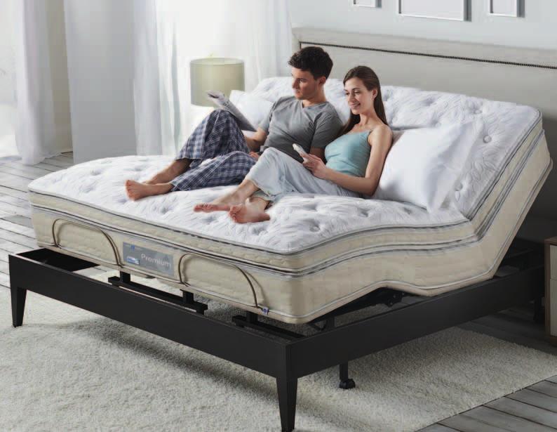

1 Adjustable Base Assembly Instructions
2 Welcome and Congratulations Congratulations on your purchase of a Sleep Number bed! You re about to join the 8 million people who ve traded their innerspring mattresses for the most innovative sleep surface ever. The technology behind the Sleep Number bed is one that recognizes the unique sleeping needs of every individual, which vary according to comfort preference, body type, height, weight, sleeping position, and other health and lifestyle factors. By creating a fully personalized sleep surface, your new Sleep Number bed offers you customized comfort that can significantly improve your sleep quality. What s Inside With your new SLEEP NUMBER adjustable base, you ll enjoy the benefits of better sleep for years to come. In this manual we ve included everything you ll need to know for setup, so you can start your Sleep Number experience tonight. First, you ll need to remove your old bed. Next, we ll guide you through assembling the base step-by-step. And, finally the best part you can indulge in the personalized comfort of your Sleep Number bed. You ll enjoy years of the latest generation of sleep comfort and technology in your Sleep Number bed. Our commitment to quality is at the heart of our manufacturing process and every Sleep Number bed is designed and crafted in the USA. Our focus on constant innovation, value, and customer satisfaction has repeatedly earned us the Consumers Digest Best Buy award. We thank you for your purchase and wish you years of personal comfort and restful sleep. Full/Queen Base Assembly... pg 4 King/Cal King/Split King Base Assembly... pg 12 Hand Control Function... pg 21 Headboard Bracket Assembly... pg 22 Troubleshooting... pg 26 Warranty... pg

3 Full/Queen Assembly Full/Queen Base Assembly 1 Locate Box 1 and Box 2 2 Cut and Remove Plastic Bands on Box 1 Caution: Exercise caution when using sharp tools. The danger of injury is possible if tools are not used properly. 3 Open Box and Remove Packaging Open Box 1 to reveal one (1) adjustable base deck assembly and one (1) setup/owner guide Remove protective plastic covering from adjustable deck assembly 4 Unfold Deck Assembly Full/Queen Assembly 2 1 Boxes are marked as shown. 4 5


4 Full/Queen Assembly 5 Position Deck Assembly Bottom side up 6 Cut Plastic Bands and Open Box 2 Open hardware box and verify contents Open hand control box and verify contents Cut zip ties and remove edge packing and mattress retainer bar Parts and Components Hand Control 1 Wrench 1 Full/Queen Full/Queen Assembly Bolt 8 Leg Support Assembly 2 Hand Control Box Plastic End Cap 4 Hardware Box Bushing 2 Tags located at head end 7-inch Leg 4 4-inch Leg 4 Caster 4 Headboard Bracket Assembly Kit 2 Mattress Retainer Bar Zip-tied to frame 1 Boxes are marked as shown. 6 7
 with head end of deck assembly.")
 using wrench included 8 Prepare Leg Support")
 Remove nylon insert locking nuts and outside bushings NOTE: Retain hardware for attachment of leg")


5 Full/Queen Assembly 7 Remove Base Assembly From Box Carefully remove steel base assembly from box Match head end of base assembly (indicated by labels on both components) with head end of deck assembly. Position steel base assembly so four (4) side holes (2 left, 2 right) line up with holes in deck assembly. Insert bolts in diagonal fashion (numerical sequence shown in photo) using wrench included 8 Prepare Leg Support Assemblies Locate leg support assembly connections at the foot end of the adjustable base (see photos at left and below) Remove nylon insert locking nuts and outside bushings NOTE: Retain hardware for attachment of leg support assemblies. 9 Position Flanges Position foot support flanges to line up with holes in deck Insert mounting bolts in flanges Do not tighten NOTE: Flanges are universal for left or right. They can be turned and manipulated to fit either side of the base. 10 Install Leg Support Assemblies Install flat end of leg support assembly on stud in steel base assembly Reinstall outside bushing and nylon insert locking nut Do not tighten Repeat for other leg support assembly Full/Queen Assembly Do not tighten important safety notice: At least two (2) people are recommended for handling and moving adjustable bed base. Leg Support Assembly Leg Support Assembly Connections Steel Base Frame Nylon Insert Locking Nut Outside Bushing 1 Hole Hole 4 3 Hole Hole 2 Nylon Insert Locking Nut Steel Base Frame Stud Outside Bushing Flat end of Leg Support Assembly Foot Support Flange Flat end of Leg Support Assembly Tags located at head end 8 9

 casters in ends of legs (casters add 2½ inches to overall base height)")
6 Full/Queen Assembly 11 Tighten Bolts and Cap Frame Ends Firmly tighten all eight (8) bolts in base assembly and leg support assemblies. Tighten nylon insert locking nuts on leg support assemblies until snug (end of stud indented approximately 1/16 from outside edge of nylon insert. See photo A) Do not overtighten 12 Add Legs Your Sleep Number adjustable base comes with both 4-inch and 7-inch legs. Determine the desired height of your base and screw the appropriate set of legs into the base assembly Optional: Insert four (4) casters in ends of legs (casters add 2½ inches to overall base height) 13 Flip Base Untie electrical power cord and extend out Carefully rotate adjustable base topside-up Plug electrical power cord into wall 15 Install Mattress Retainer Bar Insert into bushings and press down until horizontal section is firmly against deck assembly Full/Queen Assembly NOTE: Insert plastic end caps into (4) cross frame ends (see photo B) NOTE: Make sure caster brake is engaged once bed is positioned. 14 Install Bushings A Missing photo A Cross Frame End Install two (2) mattress retainer bushings in locator pin holes by pressing firmly into place Outside Edge of Nylon Insert Flat End of Leg Support Assembly B Mattress Retainer Bar Cross Frame End Bushings (Installed) Caster Brake Plastic End Cap (Installed) Foot Foot 10 You re Done! Next Step u Hand Control Function u Page 22 11

7 King/Cal King/Split King Base Assembly 1 Locate Two Box 1s and Two Box 2s 2 Cut and Remove Plastic Bands on Box 1 3 Open Box and Remove Packaging 4 Unfold Deck Assembly NOTE: You will do steps 1 13 for both bases for King/Cal King/Split King models. Caution: Exercise caution when using sharp tools. The danger of injury is possible if tools are not used properly. Open Box 1 to reveal one (1) adjustable base deck assembly and one (1) setup/owner guide 2 Remove protective plastic covering from adjustable deck assembly Boxes are marked as shown
8 Parts and Components King/Cal King Split King 5 Position Deck Assembly Bottom side up 6 Cut Plastic Bands and Open Box 2 Open hardware box and verify contents Hand Control 1 2 Tags located at head end Open hand control box and verify contents Cut zip ties and remove edge packing and mattress retainer bar Hand Control Box Hardware Box Wrench 1 1 Bolt Leg Support Assembly 4 4 Plastic End Cap 8 8 Bushing inch Leg inch Leg 8 8 Caster 8 8 Headboard Bracket Assembly Kit 2 2 DC Connector Cable* * For use with King or Cal King bases only to allow (1) hand control to operate both bases. Only one included in one Box Mattress Retainer Bar Boxes are marked as shown. Zip-tied to frame
9 7 Remove Base Assembly From Box 8 Prepare Leg Support Assemblies 9 Position Flanges 10 Install Leg Support Assemblies Leg Support Assembly Connections Carefully remove steel base assembly from box Match head end of base assembly (indicated by labels on both components) with head end of deck assembly. Position steel base assembly so four (4) side holes (2 left, 2 right) line up with holes in deck assembly. Insert bolts in diagonal fashion (numerical sequence shown in photo) using wrench included Do not tighten important safety notice: At least two (2) people are recommended for handling and moving adjustable bed base. Locate leg support assembly connections at the foot end of the adjustable base (see photos at left and below) Remove nylon insert locking nuts and outside bushings NOTE: Retain hardware for attachment of leg support assemblies. Steel Base Frame Position foot support flanges to line up with holes in deck Insert mounting bolts in flanges Do not tighten NOTE: Flanges are universal for left or right. They can be turned and manipulated to fit either side of the base. Leg Support Assembly Install flat end of leg support assembly on stud in steel base assembly Reinstall outside bushing and nylon insert locking nut Do not tighten Repeat for other leg support assembly Outside Bushing Nylon Insert Locking Nut 1 Hole Hole 4 3 Hole Hole 2 Nylon Insert Locking Nut Steel Base Frame Stud Outside Bushing Flat end of Leg Support Assembly Foot Support Flange Flat end of Leg Support Assembly Tags located at head end 16 17


10 11 Tighten Bolts and Cap Frame Ends A B Firmly tighten all eight (8) bolts in base assembly and leg support assemblies. Tighten nylon insert locking nuts on leg support assemblies until snug (end of stud indented approximately 1/16 from outside edge of nylon insert. See photo A) Do not overtighten NOTE: Insert plastic end caps into four (4) cross frame ends (see photo B) Missing photo A Cross Frame End Outside Edge of Nylon Insert Flat End of Leg Support Assembly 12 Add Legs Your Sleep Number adjustable base comes with both 4-inch and 7-inch legs. Determine the desired height of your base and screw the appropriate set of legs into the base assembly Optional: Insert four (4) casters in ends of legs (casters add 2½ inches to overall base height. NOTE: Make sure caster brake is engaged once bed is positioned. 13 Repeat Assembly for Second Base For King and Cal King models, repeat steps 1 12 before proceeding to step 14 For Split King models, repeat steps 1 12, then proceed to step 15 (skip step 14) 14 Install Connector Cable (King and Cal King models only) A DC connector cable connects both bases for operation with one hand control Carefully position both bases approximately 2 feet apart on edge, with underside of both bases facing inward. Be sure both bases are oriented the same way (heads together, foot ends together). Locate base equipped with the wired hand control. Unplug hand control and set aside Plug first dual DC connector cable plug into the insertion receptacle on the first motor IMPORTANT SAFETY NOTICE: Insert carefully. Line up pins in plug with holes in insertion receptacle. Push in as far as plug will go. Plug second dual DC connector cable plug into the second insertion receptacle following the same instructions Insert DC wired hand control plug into dual DC connector cable receptacle Carefully rotate both bed bases from edge position toward each other to topside-up position and align together to create the King or Cal King unit Untie electrical power cord and extend out, then plug into wall Do not obstruct power or hand control cords Location of Hand Control Dual DC Connector Plug (for second base) Insertion Receptacle Cross Frame End Dual DC Connector Cable (to hand control) Caster Brake Hand Control Plug Installed Dual DC Connector Plug Hand Control Plastic End Cap (Installed) 18 19


11 Adjustable Base Hand Control Function 15 Flip Base 17 Install Mattress Retainer Bar Untie electrical power cord and extend out Carefully rotate adjustable base topside-up Insert into bushings and press down until horizontal section is firmly against deck assembly Plug electrical power cord into wall 16 Install Bushings Install two (2) mattress retainer bushings in locator pin holes by pressing firmly into place Head Up Button Press and hold to raise the head section. Head/Foot Up Button Press and hold to raise the head and foot sections simultaneously. Foot Up Button Press and hold to raise the foot section. Head Down Button Press and hold to lower the head section. Head/Foot Down Button Press and hold to lower the head and foot sections simultaneously. Foot Down Button Press and hold to lower the foot section. Hand Control Function Mattress Retainer Bar Bushings (Installed) Foot Foot 20 21


 headboard bracket channel to one (1) headboard channel connector.")
 1-inch long hex head bolts/nuts Repeat procedure to attach the other headboard bracket flange Slide headboard bracket assemblies (in or out) to achieve a distance of 1½ inches")
 between the edge of the bed base and headboard bracket flanges Full size base Mounting Holes Headboard Bracket Assembly Queen, King & Cal King size base Mounting Holes (2) 1½")
12 Headboard Bracket Assembly (optional) 1 Install Optional Headboard Brackets 2 Position Headboard Channel Connector 3 Attach Headboard Bracket Channel 4 Attach Headboard Bracket Flange Headboard brackets are only needed for non-freestanding headboards Use the hand control to raise the head section of the bed to access the bed base frame Locate the headboard bracket assembly kit. On one (1) side of the bed base frame, locate two (2) holes for headboard channel connector mounting For Full size beds use inner mounting holes. For Queen, King, Cal King and Split King beds, use outer mounting holes Position headboard channel connector so the flat side is flush against bed base frame. Attach headboard channel connector to the bed base frame using two (2) 1½-inch long hex head bolts/nuts Headboard Channel Connector Using two (2) 3-inch long carriage bolts/nuts, attach one (1) headboard bracket channel to one (1) headboard channel connector. Hand-tighten bolts/nuts (loosely) to allow adjustment of the headboard bracket channels Attach one (1) headboard bracket flange to one (1) of the headboard bracket channels with two (2) 1-inch long hex head bolts/nuts Repeat procedure to attach the other headboard bracket flange Slide headboard bracket assemblies (in or out) to achieve a distance of 1½ inches (38.1 mm) to 2 inches (50.8 mm) between the edge of the bed base and headboard bracket flanges Full size base Mounting Holes Headboard Bracket Assembly Queen, King & Cal King size base Mounting Holes (2) 1½ Long Hex Head Bolts and Nuts Headboard Channel Connector Headboard Bracket Channel 1.5 to 2 Headboard Bracket Flange (2) 1 Long Hex Head Bolts and Nuts Headboard Bracket Assembly (2) Headboard Channel Connector Mounting Holes Slide headboard bracket assemblies in or out to achieve position 22 23


13 Advisory Headboard Bracket Assembly 24 5 Adjust and Secure Firmly tighten the 3-inch long carriage bolts on both headboard bracket channels Measure the distance (center-to-center) between the mounting holes in the headboard Measure the center-to-center distance between the mounting slots of the headboard bracket flanges If headboard bracket flange adjustment is required to accept the headboard, remove the 1-inch long hex head bolts and move flanges side-to-side for the adjustment. Reinstall bolts. Tighten all headboard mounting bolts Measure flange slots center-to-center to check headboard hole location. Remove 1-inch long hex head bolts and relocate flanges to achieve center-to-center distance required for headboard mounting holes. 6 Install Headboard Securely install your headboard IMPORTANT SAFETY NOTICE: The bottom of the headboard cross member must be positioned so that there is no more than 3 inches (76.2mm) between the headboard and the top of the mattress. Do not exceed 3 inches (76.2mm) in order to avoid a person or pet being caught in the space (referenced below) while the bed is in motion. Failure to follow these instructions could result in serious personal injury or death. 3 MAX. Caution: Headboard cross member location must not exceed 3 inches (76.2mm) from the top of the mattress. Important: Read the following information carefully before using this product This Sleep Number adjustable base has been quality engineered with design features to assure comfort and safety when operated properly. Electrical Grounding This product is equipped with a polarized or grounded electrical power cord. The power cord will only fit into a grounded, electrical surge protection device (not included) or a grounded electrical outlet. Important Safety Notice: For optimum adjustable bed operation, use a grounded, electrical surge protection device (not included). Failure to use a surge protection device could compromise safety or cause product malfunction. Warranty Warning Do not attempt to open the motor or hand control. The product warranty will be void if these components are tampered with. Do not attempt to alter component wiring or adjust or modify the structure of the product in any way or the warranty will be void. Any repair or replacement of adjustable bed parts must be performed by authorized personnel. Lubrication This product is designed to be maintenance free. The lift motors are permanently lubricated and sealed no additional lubrication is required. Do not apply lubricant to lift motor lead screws or any nylon nuts or the bed may inadvertently creep downward from the elevated position. PRODUCT RATINGS The bed lift motors are not designed for continuous use. Reliable operation and full life expectancy will be realized as long as the lift motors do not operate any more than five (5) minutes over a thirty (30) minute period, or approximately 15% duty cycle. Any attempt to circumvent or exceed product ratings will shorten the life expectancy of the product and may void the warranty. The recommended weight restrictions for Sleep Number adjustable bases are Full, Queen: 450 lb (204 kg); King, Cal King, Split King: 900 lb (408 kg). The bed will structurally support the recommended weights distributed evenly across the head and foot sections. This product is not designed to support or lift this amount in the head or foot sections alone. Note: exceeding the recommended weight restrictions could damage the adjustable bed and void the warranty. For best performance, consumers should enter and exit the adjustable bed with the bed in the flat (horizontal) position. DO NOT SIT ON THE HEAD OR FOOT SECTIONS WHILE IN THE RAISED POSITION. UL (Underwriters Laboratories) listed components. CFR 1633 approved for use with most mattresses. Made in USA. SMALL CHILDREN / PETS WARNING After the bed is unboxed, immediately dispose of packaging material as it can smother small children and pets. To avoid injury, children or pets should not be allowed to play under or on the bed. Children should not operate this bed without adult supervision. HOSPITAL use DISCLAIMER This bed is designed for in-home use only. It is not approved for hospital use and does not comply with hospital standards. Do not use this bed with tent type oxygen therapy equipment or use near explosive gases. fcc compliance Electrical components are rated for 110/120 voltage, 60Hz, 3.9 amp. Components meet Class B digital device rating (Part 15, FCC rules) for residential use. Raising/lowering mechanisms The raise/lower feature will emit a minimal humming sound during operation. This is normal. During operation, the lift arm wheels make contact with the platform support of the bed. This applies slight tension on the moving components and resonance is reduced to a minimum level. If excessive noise or vibration is experienced, reverse the movement action (up or down) of the bed with the hand control. This should realign the bed s activating mechanisms to the proper operational position. Advisory 25
14 Troubleshooting Warranty Additional Terms and Conditions Troubleshooting/Warranty In the event the Sleep Number adjustable base fails to operate, investigate the symptoms and possible solutions provided below. No features of the adjustable bed will activate. Verify power cord is plugged into a working, grounded electrical outlet. A grounded, electrical surge protection device is recommended. Test outlet by plugging in another working appliance. Unplug power cord, wait 30 seconds and plug in to reset electronic components. Electrical circuit breaker may be tripped. Check electrical service breaker box to verify. Defective surge protection device. Head or foot section will elevate, but will not return to the horizontal (flat) position. Bed mechanism may be obstructed. Elevate bed and check for obstruction. Remove obstruction. Head section may be too close to the wall. Leggett & Platt, Incorporated ( L&P ) warrants this adjustable bed to the consumer who is the original purchaser (the purchaser ), subject to the terms and conditions set forth herein. This warranty begins on the warranty commencement date which is the date of purchase for new unused beds and the date of manufacture for beds that have been used as floor or display models. Thus, on a floor model bed, the warranty is a portion of the limited 25 year warranty. full 2 year warranty This adjustable bed is warranted against defects in the workmanship or materials for a period of two (2) years from the warranty commencement date. Upon notice during the first two (2) years after the warranty commencement date, L&P will repair or replace (at no cost to the purchaser) any defective adjustable bed part, and L&P will pay all authorized labor and transportation costs associated with the repair or replacement of any parts found to be defective. 5 YEAR LIMITED WARRANTY During the third through the fifth year from the warranty commencement date, upon receipt of notice, L&P will replace any adjustable bed part found to be defective. This limited five (5) year warranty shall not apply unless the defective part is returned to L&P within ten (10) days of purchaser s receipt of the replacement part. Purchaser shall pay all service and transportation costs related to the replacement of the defective part. 25 year LIMITED WARRANTY Upon notice during the sixth year through the twenty-fifth year from the warranty commencement date, L&P will replace, upon terms and conditions set forth in this paragraph, any mechanical bed part found to be defective. Electronics, electrical components, drive motors and massage motors are excluded. This limited twenty-five (25) year warranty shall not apply unless the defective part is returned to L&P within ten (10) days of purchaser s receipt of the replacement part. In years 6 25, purchaser shall pay all service and transportation costs related to the replacement of the defective part. This warranty does not apply; (a) to any damage caused by the purchaser; (b) if there has been any repair or replacement of adjustable bed parts by unauthorized personnel; (c) if the adjustable bed has been mishandled (whether in transit or by other means), subjected to physical or electrical abuse or misuse, or otherwise operated in any manner inconsistent with the operation and maintenance procedures outlined in this document and this warranty; (d) to damage to mattresses, fabric, cables, electrical cords or items supplied by dealers. Contact the dealer for warranty information on these items; (e) if there has been any modification to the adjustable bed without prior written consent by L&P; (f) to costs for unnecessary service calls, including costs for in-home service calls solely for the purpose of educating the consumer about the adjustable bed or finding an unsatisfactory power connection; (g) if the recommended weight restriction is not followed (refer to advisory section), the warranty will be void. Repairs to or replacement of an adjustable bed or its components under the terms of this limited warranty will apply to the original warranty period and will not serve to extend such period. The decision to repair or to replace defective parts under this warranty shall be made, or cause to be made, by L&P at its option and in its sole discretion. Repair or replacement shall be the sole remedy of the purchaser. There shall be no liability on the part of L&P for any special, indirect, incidental, or consequential damages or for any other damage, claim, or loss not expressly covered by the terms of this warranty. This limited warranty does not include reimbursement for inconvenience, removal, installation, setup time, loss of use, shipping, or any other costs or expenses. Leggett & Platt or its service technicians shall not be responsible for moving furniture or any other items not attached to the adjustable bed in order to perform service on the adjustable bed. It is the sole responsibility of the purchaser to provide adequate space and accessibility to the adjustable bed. In the event that the technician is unable to perform service due to lack of accessibility, the service call will be billed to the purchaser and the service will have to be rescheduled. L&P makes no other warranty whatever, express or implied, and all implied warranties of merchantability and fitness for a particular purpose are disclaimed by L&P and excluded from this agreement. Some states do not allow the exclusion or limitation of incidental or consequential damages, so the above limitation or exclusion may not apply to every purchaser. This warranty gives the purchaser specific legal rights, and the purchaser may also have other rights, which may vary from state to state. This warranty is valid in all 50 states, Puerto Rico, and Canada. CONTACT INFORMATION: Select Comfort, Customer Service Department, 6105 Trenton Lane North, Minneapolis, MN 55442, Terms and Conditions 26 27
: Monday Friday Saturday Sunday 8 a.m. 6 p.m. 8:30 a.m. 5 p.m. Closed 9800 59th Avenue North Minneapolis, MN 55442 118175 3/13")
15 Help is just a click or phone call away If you ever have product questions or need additional assistance obtaining optimal comfort, please visit us at: sleepnumber.com or call Representatives are available (Central Standard Time): Monday Friday Saturday Sunday 8 a.m. 6 p.m. 8:30 a.m. 5 p.m. Closed th Avenue North Minneapolis, MN /13
QVC Adjustable Base Assembly Instructions
 QVC Adjustable Base Assembly Instructions Welcome and Congratulations Congratulations on your purchase of a SLEEP NUMBER bed! You re about to join the more than 8 million people who ve traded their innerspring
c EDR /11. ShipShape OWNERS MANUAL. [ power foundations ]
![c EDR /11. ShipShape OWNERS MANUAL. [ power foundations ]](/thumbs/87/96491649.jpg "c EDR /11. ShipShape OWNERS MANUAL. [ power foundations ]") 99301115-c EDR11746 4/11 ShipShape OWNERS MANUAL [ power foundations ] contents Advisory... 4 Assembly... 6 Hand Control Function... 15 Accessories... 16 Troubleshooting... 17 1-2-Lifetime Warranty...
99301115-c EDR11746 4/11 ShipShape OWNERS MANUAL [ power foundations ] contents Advisory... 4 Assembly... 6 Hand Control Function... 15 Accessories... 16 Troubleshooting... 17 1-2-Lifetime Warranty...
contents Advisory... 3 Acoustics... 4 Installation... 5 Remote Control Function... 11
 owners manual 50 contents Advisory... 3 Acoustics... 4 Installation... 5 Remote Control Function... 11 Tandem Syncing (One remote control operating both bases in tandem)... 12 Troubleshooting... 13 1-2-10
k EDR /11. S cape OWNERS MANUAL. S cape Platform. Silhouette. Pro-motion. Bronze. [ power foundations ]
![k EDR /11. S cape OWNERS MANUAL. S cape Platform. Silhouette. Pro-motion. Bronze. [ power foundations ]](/thumbs/87/96491583.jpg "k EDR /11. S cape OWNERS MANUAL. S cape Platform. Silhouette. Pro-motion. Bronze. [ power foundations ]") 99300787-k EDR11739 4/11 OWNERS MANUAL S cape S cape Platform Silhouette Pro-motion Bronze [ power foundations ] contents Advisory... 3 Acoustics... 5 Installation... 6 Turnbuckle Adjustment... 18 Troubleshooting...
99300787-k EDR11739 4/11 OWNERS MANUAL S cape S cape Platform Silhouette Pro-motion Bronze [ power foundations ] contents Advisory... 3 Acoustics... 5 Installation... 6 Turnbuckle Adjustment... 18 Troubleshooting...
The Sleep Number Adjustable Base Assembly instructions / Owner guide
 The Sleep Number Adjustable Base Assembly instructions / Owner guide ship-friendly packaging system quick and easy setup made in USA quality adjustable bed base 99301149-c EDR11623 8/10 CONTENTS Assembly...
Adjustable Base. CONTENTS Advisory Setup and Installation Innova Wired Hand Control year Warranty 1-10
 Adjustable Base #201 Wired Owner Manual CONTENTS Advisory Setup and Installation Innova Wired Hand Control 1-2-10 year Warranty 1-10 WARNING Attention: Read the following information before using this
c EDR /11 OWNERS MANUAL. [ power foundations ]
![c EDR /11 OWNERS MANUAL. [ power foundations ]](/thumbs/91/107132452.jpg "c EDR /11 OWNERS MANUAL. [ power foundations ]") 99301178-c EDR11777 4/11 OWNERS MANUAL [ power foundations ] contents Advisory... 4 Acoustics... 8 Assembly... 9 Bronze Hand Control Operation... 13 Bronze Tandem Setup (king size power foundation)...
99301178-c EDR11777 4/11 OWNERS MANUAL [ power foundations ] contents Advisory... 4 Acoustics... 8 Assembly... 9 Bronze Hand Control Operation... 13 Bronze Tandem Setup (king size power foundation)...
CONTENTS. Advisory Acoustics Installation Remote Control Function Remote Control Programming Troubleshooting...
 owners manual 100 CONTENTS Advisory... 4 Acoustics... 6 Installation... 7 Remote Control Function... 10 Remote Control Programming... 11 Troubleshooting... 15 Accessories... 16 1-2-10 Warranty... 17 If
adjustable base owners manual
 adjustable base owners manual leesa.com contents Parts... 3 Assembly... 4 Remote Control Function... 7 Remote Control Programming... 8 Troubleshooting... 9 Accessories... 10 Warranty... 11 Advisory...
owners manual 100 I/C-UBL
 owners manual 100 I/C-UBL contents Advisory... 4 Acoustics... 6 Installation... 7 Remote Control Function... 10 Remote Control Programming... 11 Troubleshooting... 14 Accessories... 15 1-2-10 Warranty...
CONTENTS. Advisory Acoustics Fabric Cleaning Information Installation Power Down Operation Underbed Light...
 owners manual 300 CONTENTS Advisory... 3 Acoustics... 5 Fabric Cleaning Information... 5 Installation... 6 Power Down Operation... 9 Underbed Light... 11 Remote Control Function... 12 Remote Control Programming...
Adjustable Base Avante Garde Wireless. Owner Manual. OKIN Wireless Remote #Avante Garde Adjustable Bed Base
 OKIN Wireless Remote #Avante Garde Adjustable Bed Base Head Buttons Used to raise or lower the head of the bed base. Zero Gravity button Preprogrammed for optimum comfort and relaxation position Memory
User Manual. Posture+ Adjustable Base. For customer service call:
 User Manual Posture+ Adjustable Base For customer service call: 1-877-707-7533 1 IMPORTANT INFORMATION PLEASE READ THESE INSTRUCTIONS THOROUGHLY BEFORE USING THIS PRODUCT. PROPER OPERATION OF YOUR ADJUSTABLE
Adjustable Base PB873 Wireless. Owner Manual. PB873 OKIN Wireless Remote Adjustable Bed Base. With OKIN Refined Control and Children Safety Lock
 PB873 OKIN Wireless Remote Adjustable Bed Base Head Buttons Used to raise or lower the head of the bed base. Zero Gravity button Preprogrammed for optimum comfort and relaxation position Memory Button
OWNER S MANUAL The CLASSIC Adjustable Bed Frame
 OWNER S MANUAL The CLASSIC Model Number: RI-AB1-A25-WH This product and all our bedding products are covered by one or more of the following issued and pending U.S. patents including Nos. 7448100, D657157,
 CUSTOMER SERVICE: 800-973-8374 Frame Assembly Instructions Headboard Installation E 1. Use the remote control to raise the head of the adjustable foundation in order to gain access to the foundation
Owner S Manual. Adjustable Base # ECZ04R8Z Wireless. CONTENTS Advisory Setup and Installation Wireless Hand Control year Warranty
 higher angled bed Adjustable Base # ECZ04R8Z Wireless WHEN TWO BEDS DO NOT ALIGN: on the higher angled bed of the two, use a 19mm wrench to turn the nuts on the new LEVEL RIGHT counterclockwise to adjust
CONTENTS. Advisory Acoustics Fabric Cleaning Information Installation Remote Control Function... 10
 owners manual CONTENTS Advisory... 3 Acoustics... 5 Fabric Cleaning Information... 5 Installation... 6 Remote Control Function... 10 Remote Control Programming... 11 Troubleshooting... 13 1-3-25 Warranty...
k EDR /12. Prodigy OWNERS MANUAL. English / Spanish. [ adjustable bases ]
![k EDR /12. Prodigy OWNERS MANUAL. English / Spanish. [ adjustable bases ]](/thumbs/72/66628024.jpg "k EDR /12. Prodigy OWNERS MANUAL. English / Spanish. [ adjustable bases ]") 99301078-k EDR12091 11/12 Prodigy OWNERS MANUAL English / Spanish [ adjustable bases ] CONTENTS Advisory... 3 Acoustics... 5 Installation... 6 Prodigy Remote Control Function...15 Prodigy Remote Control
99301078-k EDR12091 11/12 Prodigy OWNERS MANUAL English / Spanish [ adjustable bases ] CONTENTS Advisory... 3 Acoustics... 5 Installation... 6 Prodigy Remote Control Function...15 Prodigy Remote Control
OWNER S MANUAL The SUMMIT Adjustable Bed Frame
 ALL IN ONE FILE-SUMMIT_Layout 4 4/24/17 9:05 PM Page 1 OWNER S MANUAL The SUMMIT Adjustable Bed Frame Model Number: RI-ABTL-A25-PWCB3-SB-UCLK-SRC-110 Serial Number: This product and all our bedding products
contents Advisory... 4 Acoustics... 6 Installation... 7 Remote Control Function Remote Control Programming Power Down Operation...
 owners manual L-132 contents Advisory... 4 Acoustics... 6 Installation... 7 Remote Control Function... 14 Remote Control Programming... 15 Power Down Operation... 19 Troubleshooting... 22 Accessories...
owners manual
 owners manual www.simmons.com contents Advisory... 3 Acoustics... 5 Assembly... 6 Renew + Remote Control Function... 13 Renew + Remote Control Programming... 14 Power Down Function... 18 USB Station Relocation
owners manual G-122 NWH G-122 G-122 USB Simplicity 3.0 S-cape 2.0 / S-cape LPAdjustableBases.com
 owners manual G-122 NWH G-122 G-122 USB S-cape 2.0 / S-cape + 2.0 / Simplicity 3.0 Simplicity 3.0 S-cape 2.0 / S-cape + 2.0 LPAdjustableBases.com CONTENTS Advisory... 4 Acoustics... 6 Installation...
owners manual G-122 NWH G-122 G-122 USB Simplicity 3.0 S-cape 2.0 / S-cape LPAdjustableBases.com
 owners manual G-122 NWH G-122 G-122 USB S-cape 2.0 / S-cape + 2.0 / Simplicity 3.0 Simplicity 3.0 S-cape 2.0 / S-cape + 2.0 LPAdjustableBases.com contents Advisory... 4 Acoustics... 6 Installation...
Reverie 3EM Wireless Power Base
 Reverie 3EM Wireless Power Base Owner s Manual and Reference Guide REV: 2016-08-03 TW Manual Part No. D1103-301-3EM Manual Part No. PT-MAN-3EM Copyright 2016. All Rights Reserved. Ascion LLC. Reverie 3EM
Reverie 3E Adjustable Foundation
 Reverie 3E Adjustable Foundation Owner s Manual and Reference Guide REV: 2014-01-14 Manual Part No. D1103-301-3E Copyright 2014. All Rights Reserved Ascion LLC. Reverie 3E Adjustable Foundation Table Of
Prodigy CE. owners manual. LPAdjustableBases.com R-142
 Prodigy CE owners manual R-142 LPAdjustableBases.com CONTENTS Advisory... 4 Assembly... 6 Remote Control Function... 10 Remote Control Programming... 11 Power Down Operation... 14 Troubleshooting... 16
owners manual LPAdjustableBases.com D-122 D-222 D-222S ENGLISH SPANISH FRENCH
 Menu owners manual D-122 D-222 D-222S ENGLISH SPANISH FRENCH LPAdjustableBases.com contents Advisory... 4 LP Sense Technology... 6 Acoustics... 8 Fabric Cleaning Information... 8 Installation... 9 D-122
owners manual!d-122!d-222!d-222s
 Menu owners manual!d-122!d-222!d-222s!english!spanish!french LPAdjustableBases.com CONTENTS Advisory... 4 LP Sense Technology... 6 Acoustics... 8 Fabric Cleaning Information... 8 Installation... 9 D-122
owners manual LPAdjustableBases.com Queen Split King
 owners manual Queen Split King LPAdjustableBases.com CONTENTS Advisory... 4 Acoustics... 6 Fabric Cleaning Information... 6 Installation... 7 Power Down Operation... 12 Remote Control Function... 14 Remote
OWNERS MANUAL. Gold Series
 LUNAR OWNERS MANUAL Comfort Base Gold Series Contents Safety Information...3 What Is Included...6 Assembly - Base...7 Location of Controls - Remote...11 Operation - Main...11 Operation - Linking the Remote...12
Complete Reference Guide
 Reflexion UP Foundation Complete Reference Guide Patents pending 2014 Sealy, Inc. All Rights Reserved. 06485100 4/16/2014 Reflexion UP Foundation Limited Warranty for Reflexion UP Foundation SEALY WARRANTS
Complete Reference Guide
 Reflexion UP Foundation Complete Reference Guide Patents pending 2014 Tempur Sealy International. All Rights Reserved. 06485100 12/12/2013 Reflexion UP Foundation Limited Warranty for Reflexion UP Foundation
ADJUSTABLE COMFORT ASSEMBLY INSTRUCTIONS
 ASSEMBLY INSTRUCTIONS ASSEMBLY INSTRUCTIONS For customer service call 1-877-707-7533 or email azcustomerservice@classicbrands.org STEP 1: Carefully open the carton and remove all boxes then lay out the
REVERIE ADJUSTABLE BED OWNER S MANUAL. Reverie Deluxe Adjustable Bed. Copyright All Rights Reserved. Manual Part No.
 REVERIE ADJUSTABLE BED OWNER S MANUAL Reverie Deluxe Adjustable Bed REV: 2-25-09 Manual Part No. A-AB-A18-WWM3-C Copyright 2009. All Rights Reserved Ascion LLC. TABLE OF CONTENTS Safety Precautions...
OWNERS MANUAL American Adjustables 2618 Brick Church Pike Nashville TN,
 OWNERS MANUAL Serial #: Purchased From: Date of Purchase: 2618 Brick Church Pike Nashville TN, 37207 1-855-690-6699 2017 TABLE OF CONTENTS STOP DO NOT RETURN TO STORE. DO NOT CONTACT STORE. PLEASE CALL
Complete Reference Guide
 TEMPUR Up Complete Reference Guide Patents pending 2013 Tempur-Pedic Management, LLC. All Rights Reserved. TUF-100-01 TEMPUR Up Limited Warranty for TEMPUR Up TEMPUR-PEDIC NORTH AMERICA, LLC ( TEMPUR-PEDIC
Tech Power Base Low Profile
 Reverie 3E Tech Power Base Low Profile Owner s Manual and Reference Guide REV: 2017-1-10 Manual Part No. D1103-301-3ETLP US Manual Part No. PT-MAN-3ET-LP Copyright 2015. All Rights Reserved. Ascion LLC.
FREESTYLE Owner s Manual
 FREESTYLE Owner s Manual Contents Safety Information...2 What Is Included...5 Assembly - Base...6 Location of Controls - Remote...13 Operation - Main...14 Troubleshooting...16 Speciications...17 Technical
Complete Reference Guide
 TEMPUR Ergo Plus Complete Reference Guide Patents pending 2013 Tempur-Pedic Management, LLC. All Rights Reserved. TEPL-100-01 TEMPUR-Ergo Plus LIMITED WARRANTY FOR TEMPUR Ergo Plus TEMPUR-PEDIC NORTH AMERICA,
VESTA. Platinum Series. Owner s Manual
 VESTA Platinum Series Owner s Manual Contents Safety Information...2 What Is Included...5 Assembly - Base...6 Assembly - King Base...9 Operation - Main...9 Location of Controls - Remote...10 Troubleshooting...11
Complete Reference Guide
 TEMPUR Ergo Plus Complete Reference Guide Patents pending 2014 Tempur-Pedic Management, LLC. All Rights Reserved. TEPL-100-03 TEMPUR-Ergo Plus LIMITED WARRANTY FOR TEMPUR ERGO PLUS TEMPUR-PEDIC NORTH AMERICA,
PRIVIA OWNER S MANUAL. The. Wireless Adjustable Bed ADJUSTABLE BEDZ TO FIT YOUR LIFE CUSTOM SLEEP. Model Number: CM-ABP-A18-WWM-L-U
 OWNER S MANUAL The PRIVIA CUSTOM SLEEP Model Number: CM-ABP-A18-WWM-L-U Wireless Adjustable Bed Serial Number: (Place your serial number here for ready reference) COPYRIGHT 2011 CUSTOMATIC CUSTOM SLEEP
Freestyle OWNER S MANUAL. Wireless Adjustable Bed. The. Exclusively Designed by. Serial Number: Model Number:CM-ABD-A18-WWM-AC-SR
 ALL IN ONE FILE-FREESTYLE INNOVATIONS_Layout 4 8/18/15 10:22 PM Page 1 OWNER S MANUAL Exclusively Designed by TO FIT YOUR LIFE TM Model Number:CM-ABD-A18-WWM-AC-SR This product and all our bedding products
Relaxer OWNER S MANUAL. The. Wireless Adjustable Bed CERTIFIED & APPROVED! Model Number:RI-ABD2-A18-WWM-L-SRB. Serial Number:
 OWNER S MANUAL CERTIFIED & APPROVED! Model Number:RI-ABD2-A18-WWM-L-SRB Serial Number: (Place your serial number here for ready reference) This product and all our bedding products are covered by one or
Flex 5 Adjustable Bed Base
 TM Flex 5 Adjustable Bed Base Owner s Manual and Reference Guide Personal Comfort Flex built by: REV: 2016-07-13 TW Manual Part No. D1103-301-5DA Copyright 2016. All Rights Reserved. Personal Comfort Flex
Flex 7 Adjustable Bed Base
 TM Flex 7 Adjustable Bed Base Owner s Manual and Reference Guide Personal Comfort Flex built by: REV: 2016-07-13 TW Manual No. D1103-301-7SA Manual Part No. PT-MAN-7S-AN Copyright 2016. All Rights Reserved.
Power Lift & Recline Chair and Power Recline Only Chair
 Power Lift & Recline Chair and Power Recline Only Chair OWNER S MANUAL AND LIMITED LIFETIME WARRANTY UC540 Large Power Lift and Recline UC551 Large Power Recline Proudly Manufactured in the USA 401 Bridge
Flex 5 Adjustable Bed Base
 Flex 5 Adjustable Bed Base Owner s Manual and Reference Guide PERFORMANCE BY REV: 2017-04-10 Manual Part No. PT-MAN-4MFLX TW Part No. D1103-301-4MPC Copyright 2016. All Rights Reserved. Ascion LLC. Flex
ADJUSTABLE BASE OWNER S MANUAL
 ADJUSTABLE BASE OWNER S MANUAL table of contents Safety Precautions and Usage Statements.... 1-2 Parts List.... 3 Base Overview....4 Quick Reference Guide....5 Installation Guide...6-8 Divided Queen Installation
Avante OWNER S MANUAL. The. Wireless Adjustable Bed with Advanced Leg-Lowering LOUNGE Feature CERTIFIED & APPROVED!
 with Advanced Leg-Lowering LOUNGE Feature OWNER S MANUAL CERTIFIED & APPROVED! Model Number:RI-ABF-A18-WWM-ESF-L-AC-U-CCCBR4 Serial Number: (Place your serial number here for ready reference) This product
Reverie 7T Power Base
 Reverie 7T Power Base Owner s Manual and Reference Guide REV: 2016-05-11 Manual Part No. D1103-301-7T Copyright 2016. All Rights Reserved. Ascion LLC. Reverie 7T Power Base Table of Contents Safety Precautions...3
AUTOMATIC SUBMERSIBLE UTILITY PUMP
 AUTOMATIC SUBMERSIBLE UTILITY PUMP Zoeller is a registered trademark of Zoeller Co. All Rights Reserved. MODEL #1043-0006 Español p. 9 ATTACH YOUR RECEIPT HERE Serial Number Purchase Date Questions, problems,
Flex 9 Adjustable Bed Base
 Flex 9 Adjustable Bed Base Owner s Manual and Reference Guide PERFORMANCE BY REV: 2017-04-14 Manual Part No. PT-MAN-8T-FLX TW Manual Part No. D1103-301-8TPC Copyright 2016. All Rights Reserved. Ascion
LifeGuardLift. LifeGuard Power Lift Model #100287A OWNERS MANUAL. Rev: 2/14/11
 LifeGuardLift OWNERS MANUAL LifeGuard Power Lift Model #100287A Rev: 2/14/11 Table of Contents 1. ASSEMBLY INSTRUCTIONS A. Lift Assembly B. Setup C. Disassembly 2. CONTROL SYSTEM A. Batteries B. Battery
Owner s Manual Manual Part No. D1103-Serta-MSE REV: Copyright All Rights Reserved Ascion LLC.
 Owner s Manual Manual Part No. D1103-Serta-MSE REV: 2013-10-24 Copyright 2013. All Rights Reserved Ascion LLC. Table Of Contents Safety Precautions...3 Parts List...8 Adjustable Bed Frame Assembly...9
ODESSA. Black Series. Owner s Manual
 ODESSA Black Series Owner s Manual Contents Safety Information...2 What Is Included...5 Assembly - Base...6 Assembly - Headboard Bracket...9 Location of Controls - Remote...11 Operation - Main...12 Troubleshooting...12
SEWAGE PUMP MODEL # Zoeller is a registered trademark of Zoeller Co. All Rights Reserved. Español p. 14
 SEWAGE PUMP Zoeller is a registered trademark of Zoeller Co. All Rights Reserved. MODEL #1261-0001 Español p. 14 ATTACH YOUR RECEIPT HERE Serial Number Purchase Date Questions, problems, missing parts?
MODEL NO & UP SAFETY INSTRUCTIONS. Keep this Operator s Manual in the plastic tube behind the operator seat.
 FORM NO. 94-7276 MODEL NO. 41026-60101 & UP OPERATOR S INSTRUCTIONS HOSE REEL KIT To assure maximum safety, optimum performance, and to gain knowledge of the product, it is essential that you or any other
Owners Manual. LifeGuard Power Lift Model # Rev. 2/1/13
 Owners Manual LifeGuard Power Lift Model #100287 Rev. 2/1/13 Table of Contents 1. ASSEMBLY INSTRUCTIONS 3-5 A. Lift Assembly 3 B. Setup 3 1. Clinch Pin Location Drawings 4 2. Down Tube and Seat Assembly
Important Information
 Boat Lift Boss Installation Instructions For Metal Craft Lifts (Kit 3005.7204) Important Information Before installation, read and understand all instructions and warnings. All 120 Volt units MUST have
OWNER S MANUAL Please read and understand all precautions prior to use.
 INPUT: 120V AC 60Hz 250mA. OUTPUT: 14.4V DC 500mA. OWNER S MANUAL Please read and understand all precautions prior to use. Thank you for choosing a premium New Bright product. USA & Canada 30-Day Limited
GRINDER PUMP MODEL # Zoeller is a registered trademark of Zoeller Co. All Rights Reserved. Español p. 13
 GRINDER PUMP Zoeller is a registered trademark of Zoeller Co. All Rights Reserved. MODEL #2701-0005 Español p. 13 ATTACH YOUR RECEIPT HERE Serial Number Purchase Date Questions, problems, missing parts?
THE REFLEXION -7 ADJUSTABLE BASE. Owner s Manual
 THE REFLEXION -7 ADJUSTABLE BASE Owner s Manual THE REFLEXION -7 ADJUSTABLE BASE Table of Contents 2 4 6 8 10 12 13 14 16 Safety Precautions Parts List Installation Guide Advanced Feature Highlights Using
SUBMERSIBLE SUMP PUMPS
 SUBMERSIBLE SUMP PUMPS Zoeller is a registered trademark of Zoeller Co. All Rights Reserved. MODELS #1073-0001, 1075-0001 Español p. 9 ATTACH YOUR RECEIPT HERE Serial Number Purchase Date Questions, problems,
Owner s Manual and Assembly Instructions
 RollPlay 6V Mini Quad Owner s Manual and Assembly Instructions Model #: ACQUAD-P, ACQUAD-CAM, ACQUAD Read and understand the entire manual before assembly and operation. The vehicle must be assembled by
Installation Instructions
 85-4209 rev. 05 11-18 Installation Instructions Thank you for purchasing this anti-sway bar kit. Please read through these instructions before installation. Factory Replacement Anti-Sway Bar Kit part #1129-135
PEDESTAL SUMP PUMP. MODEL # Español p. 11. Zoeller is a registered trademark of Zoeller Co. All Rights Reserved.
 PEDESTAL SUMP PUMP Zoeller is a registered trademark of Zoeller Co. All Rights Reserved. MODEL #1084-0001 Español p. 11 ATTACH YOUR RECEIPT HERE Serial Number Purchase Date Questions, problems, missing
Installation/Operating Instructions
 RETURNING UNITS Please contact your retail store for returns. WARRANTY This unit, when properly used will provide you with years of service. It is covered under a 3 year warranty (902210-400 Watt and 902230-1500W/240V
RollSeal 1733 County Road 68 Bremen, Alabama Part No Rev Owner s Manual RS-Divider Curtain
 1. 2. 7 3. 4. RollSeal 1733 County Road 68 Bremen, Alabama 35033 256-287-7000 Part No 4801-5176 Rev 12-11-17 Owner s Manual RS-Divider Curtain Table of Contents 1 Warnings (Avertissements)... 3 2 Limited
Installation Instructions
 85-4592 rev. 08 02-18 Installation Instructions Thank you for purchasing our sway bar kit. Please read through these instructions before installation. Auxiliary Rear Anti-Sway Bar Kit for Ford F53 part
Cast Iron WARNING CAUTION. CAUTION Some parts may contain sharp edges especially as noted in manual. Wear protective gloves if necessary.
 Outdoor Fireplace 04201101 04501122 Cast Iron For Outdoor Use Only CAUTION THIS UNIT IS HEAVY! DO NOT assemble without a helper. CAUTION Some parts may contain sharp edges especially as noted in manual.
Black Diamond Motorized Flush Mount Instructions
 Black Diamond Motorized Flush Mount Instructions 1 Installation Parts List Mounting Brackets Wall Switch / Limit Setting Tool Mounting Bracket Screws & Driver Bit (#2 Robertson) Wall Switch Cable (8 Length)
AGRI-COVERTM SWITCH CONTROL INSTRUCTIONS
 AGRI-COVERTM SWITCH CONTROL INSTRUCTIONS Use these instructions in place of the rocker switch and solenoid sections in your roll tarp or ROLTECTM Electric Hopper Conversion instructions. Some installs
Users Guide for Ac-sync
 Problem solved. Users Guide for Ac-sync Thank you for choosing Anywhere Cart! The AC-SYNC is designed to sync, charge and store 1-36 ipads or tablets. Adjustable device divider bays allow fitment of any
Audi R8. Ride-on Car 5F62630 OWNER S MANUAL. Keep instructions for future reference
 Audi R8 Ride-on Car 5F62630 OWNER S MANUAL Keep instructions for future reference 1 Safety The owner s manual contains assembly, use and maintenance instructions. The vehicle must be assembled by an adult
16K and 19K Sidewinder TM Service Kit Instructions 86005
 86005 Equipment Required: Wrenches: 15/16, 1 1/8, Torque Wrench, Rubber Mallet Included Service Kit Items: 1 Qty. (1) Wear Plate 2 Qty. (6) 5/8 Conical Washer 3 Qty. (2) Wedge Bolt, 5/8-11 X 1 3/4 GRD
Source Capture Air Purification System
 Source Capture Air Purification System HA-SCP-G3 Owner s Manual Table of Contents HealthyAir HA-IFM-1111 Filter 1 Important Safety Instructions 2 Technical Specifications 3 Packaging Reference 4 Packing
Please read and understand all precautions prior to use.
 INPUT: 120V AC 60Hz 8W. OUTPUT: 13V DC 440mA. OWNER S MANUAL Please read and understand all precautions prior to use. Thank you for choosing a premium New Bright product. L897121239/JN113-16 CONTENTS Component
OWNER S MANUAL & Assembly Instructions
 OWNER S MANUAL & Assembly Instructions EWT- Olympic Plate Tree L2 X W 2 X H1 EWT-_Rev0 Revision Date -27-12 Table of Contents DANGER, WARNING, & CAUTION LABELS INFORMATION...Page - IMPORTANT SAFETY INSTRUCTIONS...Page
Hydraulic Transmission Jack, Telescopic
 Operating Instructions & Parts Manual Hydraulic Transmission Jack, Telescopic Model 4000 400 (Air Operated) Capacity 000 lbs. 000 lbs. Model 4000 Model 400 U.S. Patent No. 6,02,377! This is the safety
Use and Care Guide.
 Model # Part # 53301111 L-40-802-SV-N-BZ 53301112 L-40-802-SV-N-W Use and Care Guide LED OUTDOOR RE LIGHT Questions, problems, missing parts? Call ETi SSL Customer Service 8:30 a.m. 5 p.m., EST, Monday
SUBMERSIBLE SUMP PUMPS
 SUBMERSIBLE SUMP PUMPS Zoeller is a registered trademark of Zoeller Co. All Rights Reserved. MODEL #1099-0001 Español p. 11 ATTACH YOUR RECEIPT HERE Serial Number Purchase Date Questions, problems, missing
MARCY Elliptical Machine PL-21930
 NOTE: Please read all instructions carefully before using this product Table of Contents Safety Notice Hardware Identifier MARCY Elliptical Machine PL-21930 Assembly Instruction Parts List Computer Warranty
Read and follow all instructions. Safety can only be ensured if the walker is assembled and operated according to these instructions.
 Aqua Walker 9889 Garrymore Ln Missoula, MT 59808 888-687-3552 +1-406-549-0769 www.aquacreek.com Manual PART #: F-605UW 300 LB. [136 kg] MAXIMUM WEIGHT CAPACITY MANDATORY LEAVE THIS MANUAL WITH WALKER OWNER
Installation Instructions
 85-3195 rev. 12 04-18 Installation Instructions Thank you for purchasing this antisway bar kit. Please read through these instructions before installation. Part #1139-117 Rear Anti-Sway Bar Kit 1½ diameter
CTFRP Series Power Supplies
 CTFRP Series Power Supplies Ferroresonant Non-Standby Power Supplies User Manual Myers Power Products 6/2013 CTFRP Series Manual Chapter 1 General Information The Myers CTFRP Series Power Supply provides
5 th Airborne Sidewinder Service Kit Instructions 94316
 94316 Equipment Required: Wrenches: 15/16, Torque Wrench, Rubber Mallet 3 4 5 2 Included Service Kit Items: 1 Qty. (1) Wear Plate 2 Qty. (1) Wear Bushing 3 Qty. (1) Wear Disc 4 Qty. (4) 5/8-11x2 GRD8 Bolt
14", 18" & 24" Fiberglass Turbo Fans Installation & Operator s Instruction Manual
 14", 18" & 24" Fiberglass Turbo Fans Installation & Operator s Instruction Manual 09484:09#52
Heavy-Duty Drywall Dolly Cart
 Heavy-Duty Drywall Dolly Cart Owner s Manual WARNING: Read carefully and understand all ASSEMBLY AND OPERATION INSTRUCTIONS before operating. Failure to follow the safety rules and other basic safety precautions
Installation Instructions
 85-3511 rev. 04 11-15 Installation Instructions Polyurethane Bushing Kit for Ford F-53 (Front) (replaces OE bushings and brackets) part #4139-127 1-5/8 diameter INTRODUCTION Thank you for purchasing this
Digital Body Weight Scale Model No.: EB4074C. Questions or Concerns? (855)
") Digital Body Weight Scale Model No.: EB4074C Questions or Concerns? (855) 686-3835 support@etekcity.com 1 Thank You. Thank you for purchasing the EB4074C Digital Body Weight Scale by Etekcity. We are dedicated
Digital Body Weight Scale Model No.: EB4074C Questions or Concerns? (855) 686-3835 support@etekcity.com 1 Thank You. Thank you for purchasing the EB4074C Digital Body Weight Scale by Etekcity. We are dedicated
Instruction Manual. ATV Plow Tube System
 Instruction Manual ATV Plow Tube System Manual Conventions This manual uses the following symbols to help differentiate between different kinds of information. The safety symbol is used with a key word
OnBoard Drum Major Podium
 Assembly and Owner s Manual OnBoard Drum Major Podium CONTENTS CONTENTS................................................................................. 1 SAFETY...................................................................................
The Da-Lite Difference.
 The Da-Lite Difference. Instruction Book for Large Advantage Electrol DA-LITE SCREEN COMPANY, INC. 3100 North Detroit Street Post Office Box 137 Warsaw, Indiana 46581-0137 Phone: 574-267-8101 800-622-3737
Adjustable Angled Incline Conveyor Owners Manual with Operating Instructions
 Adjustable Angled Incline Conveyor Owners Manual with Operating Instructions Revision 012211 Table of Contents Basic Conveyor Features 3 Getting Started 4 Setting Up the Incline Conveyor 5 Belt Removal
StormPro BA Series Sump Pump
 Page 1 of 8 Marks & Meanings DANGER: Keep the pump equipment out of the reach of children! Warns that the failure to follow the directions given could cause serious risk to individuals or objects. WARNING:
BroadBand PowerShield. 20 AHr Battery. User Manual
 BroadBand PowerShield 20 AHr Battery User Manual 990-1316A 10/2004 Chapter 1 General Information The PowerShield provides a power source for broadband telephony applications. Important Safety Instructions
Model Numbers SAVI-NOTE75, SAVI-NOTE150
 Installation INSTRUCTIONS & OWNERS Manual SAVI NOTE UNDERWATER LED LIGHT Model Numbers SAVI-NOTE75, SAVI-NOTE150 Safety Precautions...2 SAVI Note Install Instructions...3-4 1 READ AND FOLLOW ALL INSTRUCTIONS
Installation Instructions
 85-3207 rev. 03 05-06 Installation Instructions Thank you for purchasing this anti-sway bar kit. Please read through these instructions before installation. Rear Anti-Sway Bar Kit for the Freightliner