Service Manual. Your Life. Your Ride. TM 6591 W. Hwy 13 Savage, MN
|
|
|
- Lindsay Riley
- 6 years ago
- Views:
Transcription
")
 890-1903 Your Life.")

1 Honda Odyssey Minivan Service Manual Main: (800) Local: (952) Fax: (952) Your Life. Your Ride. TM 6591 W. Hwy 13 Savage, MN
2
3 Honda Odyssey Minivan Service Manual # November 16, 2015
4 Table of Contents Important Item Information and Locations... 1 Battery Information - General... 7 Battery Information - Draw Test Procedure... 9 Door Troubleshooting Door Modifications Door Operation - OEM Exhaust System Exterior and Van Dimensions Fuel System Interior Kneeler Troubleshooting Kneeler Replacement Parts One Touch System Troubleshooting One Touch System Overview One Touch System - v8.0 Basic Interface One Touch System - v8.0 Advanced Interface - Setup One Touch System - v8.0 Advanced Interface - Debugger One Touch System - v8.0 Error Codes One Touch System - Relay Board Troubleshooting Ramp Troubleshooting Ramp Replacement Parts Rear Heat & Air Remote System Troubleshooting Remote System Seat Power and Airbags Suspension and Rear End... 67

5 Table of Contents Wiring Diagram - OTC System - vh8.0 w/ New Sec. ByPass Wiring Diagram - OTC System - vh Wiring - Rollx Vans Extensions to OEM - Front Left Branch Wiring - Rollx Vans Extensions to OEM - Front Right Branch Wiring - Rollx Vans Extensions to OEM - Front Right Branch Maintenance Information Warranty
6 Important Item Information and Locations OEM Main Wire Harnes (Floor Along Driver Side) (Ceiling Along Passenger side) Rollx Vans Main Wire Harness (Ceiling Along Passenger s Side) OTC Main Fuse Rollx s Vans Security System Bypass Circuit Driver Seat Detector Driver Underdash fuse relay box Power Seat Connector and OEM Sensor Assembly Cluster ITF Ramp Acces Panel Rollx Vans Door Translator OTC Fuse Panel (Under Glove Box) Passenger Sliding Door Detector Passenger Under Hood fuses OTC Relay Panel Honda Seat Detector Honda Seat ECU OTC Remote Receiver Rear Heat Kneeler One Touch Controller (OTC) Board Rear AC Page 1


 #08204-002 - DOOR DETECTOR HONDA The Rollx Vans Door Detector counts the pulses sent")
7 Important Item Information and Locations Main Fuse (Engine Compartment) The Main OTC Fuse (40 amp) is used to power all Rollx Vans components except the motors on a Rollx Vans Transfer Seat. It can be used to isolate the Rollx Vans electrical system from the OEM system. 6way Seat Fuse (40 Amp) (If Equipped) Main OTC Fuse (40 Amp) # OTC Remote Receiver (Behind Rear Passenger Quarter Panel Above OTC Relay Board) The Rollx Vans Remote Receiver operates the Rollx Vans system only when the button on a transmitter is pressed. More information can be found in the Remote System section. # RECEIVER ONLY It is powered through a 1 amp fuse in the Rollx Vans Fuse Panel. Passenger Sliding Door Detector (Behind Rear Passenger Quarter Panel Below OTC Relay Board) # DOOR DETECTOR HONDA The Rollx Vans Door Detector counts the pulses sent from the OEM door motor to determine when the door is all the way open. Its function to the OTC system is similar to a Door Open Limit Switch. It is powered through a 1 amp fuse in the Rollx Vans Fuse Panel. Page 2
 Any Rollx Vans component besides a Rollx Vans Transfer Seat Motor obtains its 12v power through this fuse panel.")
 - Rollx Vans Door Detector (1 amp fuse) - Rollx Vans OTC Board (1 amp) - Rollx Vans OTC Relay Board (Direct) -")

8 Important Item Information and Locations Transfer Seat Controller, Power Tiedown or Other Accessories (If Equipped) Ground Rollx Vans Remote Door Detector OTC Board Neutral Safety Out Ignition Hot Out OTC Fuse Panel # Amp Fuse (Under Glove Box) Any Rollx Vans component besides a Rollx Vans Transfer Seat Motor obtains its 12v power through this fuse panel. The fuse panel is powered from the main vehicle battery through a 40 amp fuse that is located near the battery. The fuse panel also has quick connections for Ignition Hot and Neutral Safety. Items powered through this location include: Standard - Rollx Vans Remote (1 amp fuse) - Rollx Vans Door Detector (1 amp fuse) - Rollx Vans OTC Board (1 amp) - Rollx Vans OTC Relay Board (Direct) - Accessories - Rollx Vans Transfer Seat Control Board - Power Tiedown - Web Tech ITF Ramp Access Plate (Behind Driver Seat) The ramp motor, activator and limit switches can be accessed by removing this plate. #OTCV8 RELAY BD OTC Relay Board (Behind Rear Passenger Quarter Panel) The Rollx Vans Relay Board is controlled by the One Touch Control Board and sends power and ground to the ramp and kneel motors. See OTC Relay Board Troubleshooting for more information. Page
 Power Seat Connector and OEM Sensor Assembly Cluster Rollx Vans installs a Power Seat Connector to")

 The neutral safety that Rollx Vans uses for its OTC Fuse Panel is achieved by tapping into OEM neutral safety location as shown.")
9 Important Item Information and Locations Kneeler Kneeler and One Touch Controller Board OTC Board Rollx Vans Power Seat Connector OEM Sensor Assembly Cluster Rollx Vans Rollover Sensor Cove #H05075 ( ONLY) Power Seat Connector and OEM Sensor Assembly Cluster Rollx Vans installs a Power Seat Connector to allow for quick removal of front seats. The OEM Seat gets its power, ground, and heat functions through this connector. Rollx Vans relocates the OEM Sensor Assembly Cluster from underneath the driver seat to the floor area in front of the driver seat so that the seat can be moved. ( ONLY) More information can be found in the Power Seat section Rollx Vans neutral safety Green wire OEM Blue wire C205 connector OEM Neutral Safety (Near Passenger Side Kick Panel) The neutral safety that Rollx Vans uses for its OTC Fuse Panel is achieved by tapping into OEM neutral safety location as shown. See OTC Wiring Diagram for more information. Page
 Rollx Vans Steering Shaft Extension Rollx Vans needs to extend the")
 #90511671003 - Lock Washer Rollx Vans Case for OEM")
")
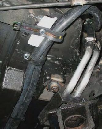
10 Important Item Information and Locations #H Extension # AD - Rubber Boot (Not Shown) Rollx Vans Steering Shaft Extension Rollx Vans needs to extend the OEM Steering Shaft as shown. #90135SF Bolt (w/ Loctite) # Lock Washer Rollx Vans Case for OEM E-Brake (Underneath Front Left of Van) #H05073 E-Brake Mounting Plate #05074 E-Bake Mounting Plate Cover Rollx s Vans Honda Security Bypass Circuit (Driver s Door) Part: # See OTC Wiring Diagram for more information. Page 5
11 Important Item Information and Locations Kneeler Honda Seat Detector (Passenger Side Near Lower B- Pillar) Rollx Vans installs the Honda Passenger Seat Detector so that the front seats can be removed without activating a DTC Error in Honda s computer. OTC Board Please see Seat Power and Airbags Section for more information. HONDA SEAT ECU ( ) ASM SEAT ECU WIRE HARNESS ( ) (2011) Page
12 Battery Information - General Measuring current draw from a battery means we are going to measure the number Electrons flowing out of the Negative Terminal of the battery and returning to the Positive Terminal. (Yes, its true, electrons flow from the negative to positive terminal of a battery.) Electron Flow is known as Current and is measured in Amperes often referred to as Amp(s). One Amp is x electrons. We will use the term Amp(s) and Milli-amps in this procedure. One Milli-amp is a thousandth of an Amp. As an example 125 Milli-amps is.125 of an Amp. The Vans we use have the Negative Terminal of the Battery attached to the frame. Current is Drawn from the battery by one or more loads. The Radio is a load. Each Microcomputer in the Van is a load. The OTC Controller is a load. The Ramp Motor is a load. A 6-Way Seat is a load. A Power Tie Down is a load. The Dome-light is a load, etc. Each load draws some amount of current determined by is design. The total current taken from the battery is the sum of all the loads currently running. If as an example, you turn the radio on, you add its current load to what ever is the draw currently being taken from the battery. The current flows out the Negative Terminal, splits up in to branches as it flows through each load, and then merges back together and flows back into the Positive Terminal. The total current flowing back into the Positive Terminal always equals the total current flowing out of the Negative Terminal. You can measure the total draw (current flow) at either terminal of the battery. Always use the Negative Terminal, its safer! The Electronic System found in Honda Vans is made up of a number of small Microcontrollers, each monitoring and controlling one or more functions in the vehicle. The Rollx Vans OTC Microcontroller is similar. One characteristic they share is the ability to put themselves into a Sleep Mode. While in sleep mode the load they take from the battery is greatly reduced. The Rollx Vans OTC goes to sleep in about ten seconds of non-use. When a Van is shutdown, the engine turned off, the key removed and the doors shut, the Honda Microcontrollers start to shut themselves down. They go to sleep in stages. You can see this happen by placing a meter capable of measuring current in series with the Negative (Black) Terminal of the battery. Over the course of several minutes the current will drop in stages from a number of Amps to a few Milli-amps. Honda spec s the current draw for a Van in Sleep Mode as between 40 and 70 Milli-amps ( Amps) depending on version and features. The Rollx Vans OTC Microcontroller is spec at 8 to 10 Milli-amps ( Amps). The Rollx Vans Remote Keyless Entry (RKE) Receiver draws Milli-amps ( Amps). Add the min and max numbers of each together and you should expect a Van to draw from 58 to 92 Milli-amps ( Amps) normally. Note: This is with no other Rollx Vans options installed. As you add options you add their load to the total. To help you better understand battery draw here are common definition of terms used to rate batteries: Amp-Hour Rating: AHR (or A/H) is a commonly used rating of a battery capacity to supply current over a period of time. The Amp-hour rating of battery capacity is calculated by multiplying the current (in amperes) by discharge time (in hours). Amp-hour battery rating is commonly used when describing sealed lead acid batteries. For example: a battery which delivers 2 amperes for 20 hours would have a 40 amp-hour battery rating (2 * 20= 40). A 40 AHR battery can supply 40 amps for 1 hour, 1 amp for 40 hours or any mathematical factor of load and time. Cold Cranking Amperage rating: CCA is the short-term discharge load in amps which a battery can sustain for 30 seconds at 0 degrees F. and not fall below 1.2 volts per cell (7.2V on 12V battery). This rating measures a burst of current that a car needs to start on a cold morning. This rating is used mainly for rating batteries for engine starting capacity. Page
13 Battery Information - General Reserve Capacity rating: RC is the number of minutes a new, fully charged battery at 80 degrees F. will sustain a discharge load of 25 amps to a cut-off voltage of 1.75 volts per cell (10.5V on 12V battery). This rating measures a continuous load on the battery. Note: As the charge of a battery is used up the battery voltage drops. Generally speaking, at 10.5 volts a battery is considered discharged. CCA and RC ratings aren t meaningful for determining the maximum current draw a battery can sustain over a period of time. The AHR is best used for this. In the vehicle world, CCA is the most common rating found for a battery, and the AHR is often not readily available. The Electronic Department is currently running a series of tests to determine the AHR and max load (for Sleep Mode), for a standard Van battery as well as a high capacity, deep discharge battery (for use with Vans with a large number of accessories). When these tests are complete we will publish the results and get them to you. Some notes on extending battery life: The Van must be put to sleep when not in use. This means the user must shut off all accessories and close all the windows and doors. If the doors are not completely shut, the Van will stay awake. The Rollx Vans Ramp and Kneel system should not be deployed! When it is, both the Honda Computer System and the Rollx Vans OTC System are awake and drawing high current. This will run the battery down very rapidly. The Van should be started and run for at least fifteen minutes daily to allow the battery to be charged. Page
14 Battery Information - Draw Test Procedure The following procedure should be used to test the current draw from any battery used in our Vans. 1) Insure the battery is fully charged. 2) Remove the key from the ignition switch. 3) Close all the doors including the Sliding doors and the Rear Tailgate. 4) Close all the windows including the Rear Vent Windows. 5) Remove the Negative (Black) cable from the battery and move it to a safe location away from both the Positive (Red) and Negative Terminals of the battery. 6) Acquire a Digital Multimeter with a 20 Amp current range function. NOTE: A standard Van can draw between 15 and 17 amps of current when it is first powered up (When the battery is reconnected). You must use a Multimeter with a 20-amp range. Using a Multimeter with a lower current range function will damage the meter if it does not have an internal fuse. If it has an internal fuse, it will be blown. NOTE: DO NOT RUN THE Rollx Vans OTC OR TRY TO START THE VAN WHEN YOU HAVE THE METER CONNECTED! YOU WILL DAMAGE THE METER! 7) Place the Function switch of the Multimeter in the 20 Amp Current Measurement position. 8) Connect the Negative (Black) Probe (wire lead) to the Black Jack on the Multimeter. 9) Most Multimeters have more then one Red Jack for the Positive (Red) Probe. They usually have one Jack for measuring AC & DC Voltage and Resistance, along with a second Jack for measuring AC & DC Current. Some Multimeters have more then one Red Jack for measuring current (three Red Jacks total). As an example a meter might have two Red Jacks, one rated for 200 Milli-amps and a second for 20 amps. You should use the 20-amp plug (or the one with the largest rating). 10) Acquire two Test Jumpers with Alligator Clips (Radio Shack # ). Attach one Jumper to the Positive (Red) Probe and the other to the Negative( Black) Probe. 11) Turn the Multimeter on. 12) Attach the other end of the Jumper clipped on the Positive (Red) meter probe to the disconnected Battery cable. NOTE: Polarity does not matter much when measuring current. A positive current is the same as negative current. Disregard the polarity indicator on the Multimeter during these tests. 13) Attach the Jumper on the Negative (Black) meter probe to the Negative Terminal of the battery. NOTE: YOU MAY GET A SPARK WHEN YOU ATTACH THE JUMPER. THIS IS NORMAL. ALL THE CURRENT BEING USED BY THE VAN IS NOW RUNNING THROUGH THE METER. AS MUCH AS AMPS). 14) The Multimeter should now show a reading. Keep you eye on the meter and watch the draw. A typical Page
15 Battery Information - Draw Test Procedure Van can have from 18 to 28 Computer modules in it. They are all woke up when power was applied to the Van by attaching your meter probes. As you watch the current reading you will note that it will start to fall. This happens as the computers in the Van decide they are not needed and put themselves to sleep. Honda says it can take up to thirty minutes for everything to go into Sleep Mode. The current should drop in stages similar to the sequence below: a. The reading will start as high as amps for a short period of time. b. It then fall to 6-8 amps for a short time. c. Then 1 to 1.5 amps for a period of time. d. It will then settle on around.800 amps (800 Milli-amps) for a while. e. Then it may drop to.100 to.200 amps (100 to 200 Milli-amps) for period of time. f. Finally it will drop all the way into Sleep mode,.040 to.100 amps (40 to 100 Milli-amps) and will stay there until the van is woke up. g. Note: The values you will see will vary from Van to Van, from Van type to type and by the number and type of accessories installed on the Van. The important thing is that it drops to a value less the 100 Milli-amps (.100 Amps) for a standard Van when it goes into Sleep Mode. 15) You can wake the van simply by opening the Drivers Side Door for a few seconds, then closing it. 16) Watch the meter again to see the Van go into sleep mode again. You should repeat this test until you are satisfied the Van s Sleep Mode is functioning correctly. Continued on next page. Page 10


16 This picture shows a complete setup for a Draw Test: Battery Information - Draw Test Procedure Note the Black Probe attached to the Negative Terminal and the Red Probe attached to the Negative Battery Cable. This picture shows a typical Multimeter. Note the Current Range Switch settings and current Probe Jack markings are all in yellow for ua (Micro-Amps), ma (Milli-amps and A (Amps). Also note that the meter has two Jacks for current measurement, 20A and ua/ma. On this meter, for our Draw Test, we would place the Function Switch in the A (for Amps) position and plug the Red Probe into the 20A Jack. The Black Probe always goes in the Black Jack. Page 11
17 This page was intentionally left blank. Page 12
18 This page was intentionally left blank. Page 13
19 Door Troubleshooting Symptom Possible Cause Remedy Van is NOT in park or neutral. Sliding Door on/off switch located on left dash is turned to the OFF position. OTC program failure Either Sliding Door window or fuel fill door are open. Place van into park or neutral Turn switch to ON position. Press OTC reset button. Close. See Door Operation - OEM for more information. Passenger sliding door does NOT OPEN with interior Rollx Vans user button. Ramp sliding door does NOT OPEN with interior OEM push buttons after pressing OTC reset button. OTC reads low voltage. Bad OTC board. Main OTC fuse (40 amp) is blown. Sliding Door on/off switch located on left dash is turned to the OFF position. Either Sliding Door window or fuel fill door are open. Van battery was reconnected without both sliding doors closed all the way. Start van's engine and press OTC reset button. If door still does not open review OTC board display and contact customer service. Press the OTC reset button and while in Idle Mode press a user button and watch the LED. Notice if OTC appears to be working properly. Review error codes stored and call customer service. Replace fuse under hood by battery. Turn switch to ON position. If the switch is OFF, the sliding doors will only operate in manual mode. Close. See Door Operation - OEM for more information. Close all doors and reconnect the battery again. Ramp sliding door does NOT attempt to CLOSE after ramp stows. Ramp sliding door kicks back when opening or closing Ramp up limit switch is not being activated properly. Either Sliding Door window or fuel fill door are open. Obstruction. Close door manually, press OTC reset button, and press Rollx Vans user button to operate system again. If door still does not attempt to close after ramp is stowed, review OTC board display and contact customer service. Close. See Door Operation - OEM for more information. Check door track for any debris and remove. Ramp sliding door opens and van kneels, but when door is all the way open, van unkneels and cycle ends. OEM Door Ajar Pin Switch (Rollx Vans Door Close signal) is never deactivated when door begins to open. If the OTC thinks the door is open and closed it will end the cycle. Examine switch / wiring. Ramp sliding door does not seal when almost closed Ramp sliding door does NOT OPEN manually with Sliding Door on/off switch located on left dash is turned to the OFF position Ramp sliding door does NOT OPEN manually from interior handle, but does from exterior handle. Ramp sliding door will NOT CLOSE manually with Sliding Door on/off switch located on left dash is turned to the OFF position Defective OEM cinch motor / Slide Motor. Door is locked. Child safety lock is activated. Door handle is not releasing. Obstruction. Operate door manually and contact customer service. Unlock door. When pulling door handle, pull handle out and then slide door to open. See OEM owner manual to deactivate child safety lock. Pull handle to disengage latch and slide to close. Check door track for any debris and remove. Page 14
20 Door Modifications RIVET #10277 (12 PER DOOR) INNER DOOR SKIN PASS, HONDA #H05180-P5 INNER DOOR SKIN DR, HONDA #H05180-D5 Page 15


21 Door Modifications LOWER DOOR ARM,HONDA SPACESHIP BRAKET #H05033 CABLE DOOR WINDOW SAFETY, HONDA #AR-HONDA2 CABLE DOOR LATCH, HONDA #AR-HONDA1 Page 16
22 Door Operation - OEM CABLE DOOR WINDOW SAFETY, HONDA #AR-HONDA2 CABLE DOOR LATCH, HONDA #AR-HONDA1 CABLE DOOR LATCH, HONDA #AR-HONDA1 Page 17
23 Door Operation - OEM Power Sliding Door Control Unit (behind rear inner trim panel) This unit receives inputs from the switches and sensors in the sliding door system and from B-CAN. It outputs to the slide motor, release actuator, and closer motor to control the movement of the doors. It also controls the sliding door beeper and indicator. Slide Motor (behind rear inner trim panel) This motor moves the door in both directions. It includes a power slide door pulser, an electromagnetic clutch and a cable tension adjuster. Power Slide Door Pulser (A)-The power slide door pulser generates pulses that are sent to the power sliding door control unit as the sliding door moves. The power sliding door control unit uses these pulses to determine the speed and position of the door. Electromagnetic Clutch (B)-This clutch engages the motor to the sliding door cables Remote Control Assembly This assembly operates cables that release the front and rear slide door latches, pulls the inner handle lower roller latch release cable, triggers the 3 remote control switches, and activates the failsafe lever cable. The assembly includes the remote control switches, the door lock actuator, the door lock, the child-proof lock, and the inside door handle linkage. Remote Control Switch 1 (A)-This switch signals the power sliding door control unit that the outside door handle is being pulled or the inside door handle is being pulled toward the open direction while the child safety lock is OFF. Remote Control Switch 2 (B)-This switch signals the power sliding door control unit that the inside door handle is being pulled toward the close position. Remote Control Switch 3 (C)-This switch signals the power sliding door control unit that the inside door handle is being pulled toward the open position while the child safety lock is ON. This switch is used for safety reasons because remote control switch 1 is not actuated when the child safety lock is ON and the inner handle is pulled toward the open position. Page 18
24 Door Operation - OEM Outer Handle Crank Assembly This assembly operates the lower roller latch cable when the inner handle lower roller latch release cable is pulled by the remote control assembly, the outer handle cable A is pulled by the outer handle or the release actuator is operated. This assembly also operates the outer handle cable B when the outer handle cable A is pulled by the outer handle or the release actuator is operated. This assembly includes the release actuator. Release Actuator (A)-When the dashboard switch, the remote transmitter, or either the inside or outside door handle is used to open or close the door, the release actuator rotates the outer handle crank assembly linkage, pulling the lower roller latch cable and the outer handle cable B. Rear Latch Assembly This assembly mechanically latches the rear of the door in the closed position. It contains the closer motor, the half-latch/full-latch switch, the base position switch, ratchet switch, and the failsafe lever. Closer Motor (A)-This motor moves the latch from the half-latched to the fully latched position to complete closing the door. Half-Latch Switch/Full-Latch Switch (B)-These switches signal the power sliding door control unit that the door has reached the half-latched position and the fully latched position-the door is fully closed. Base Position Switch (C)-This switch signals the power sliding door control unit that the closer motor is in its normal, off position. Ratchet Switch (D)-This switch provides a confirmation signal to the control unit that the operation of the half-latch and full-latch switches is accurate. Failsafe Lever (E)-This lever mechanically disconnects the closer motor from the door latch. See Emergency Stop Operation. Lower Roller Latch and Stopper Assembly (attached to lower front of slide door) This assembly is attached to the lower roller s bracket. The lower roller latch latches the door in the open position when it is fully opened. The lower roller stopper stops the door at the open window position for safety. It contains the lower roller latch and the lower roller lever as well as the lower rollers. Sliding Door Power Window Regulator Assembly This assembly moves the sliding door window in the window run channels, actuates the sliding door window position switch, and pulls the lower roller stopper cable. Page 19
25 Door Operation - OEM It contains a power window motor, position plate, and sliding door window position switch. Sliding Door Window Position Switch-This switch signals the power window control unit that the window is open at about 4 inches (about 100 mm) or more. Front Latch Assembly This assembly mechanically latches the front of the door in the closed position. Page 20
26 Page 21 Door Operation - OEM BASIC OPERATION Opening a Door with the Power Sliding Door Switch or the Remote Transmitter To open a door electrically: The Main switch must be ON. If the ignition switch is ON (II), the shift lever must be in Park or in Neutral with the foot brake or parking brake ON. If the ignition switch is turned to LOCK (0), the shift lever must be in Park. The door must be unlocked, and the fuel fill door must be closed (left door only). 1. If the Power Sliding Door Switch is used, the switch sends a signal to the power sliding door control unit for that door. If the remote transmitter is used, the door multiplex sends an open message to the power sliding door control unit for that door. 2. The power sliding door control unit sends a signal to the release actuator to unlatch the door. 3. The release actuator rotates the linkage on the outer handle crank which pulls the outer handle cable B. Outer handle cable B rotates the linkage on the remote control assembly, which pulls the front and rear latch cables. This releases the front and rear latches mechanically unlatching the door. 4. The power sliding door control unit then activates the electromagnetic clutch and starts the slide motor. The slide motor moves the cables that move the door. 5. The power slide door motor pulser senses the movement of the slide motor, and sends pulses to the power sliding door control unit. The control unit uses these pulses to judge the speed and position of the door. 6. When the power sliding door control unit judges that the door is fully open, it turns off the slide motor and the electromagnetic clutch. Opening a Door with the Inside or Outside Handle To open a door electrically: The Main switch must be ON. If the ignition switch is ON (II), the shift lever must be in Park or in Neutral with the foot brake or parking brake ON. If the ignition switch is turned to LOCK (0), the shift lever must be in Park. The door must be unlocked, and the fuel fill door must be closed (left door only). 7. The inside door handle is mechanically linked to the remote control assembly. The outside door handle is linked via the outer door handle cable A, outer handle crank, and outer handle cable B. Inner handle, child safety lock OFF-The inner handle rotates the linkage on the remote control assembly, which pulls the front and rear latch cables. This releases the front and rear latches, mechanically unlatching the door. Inner handle, child safety lock ON-The inner handle rotates the linkage on the remote control assembly, which only pulls the fail safe cable; the front and rear latch cables are mechanically disengaged from the linkage. Outer handle-the outer handle pulls the outer handle cable A, which rotates the outer handle crank. The outer handle crank assembly pulls the outer handle cable B. Outer handle cable B rotates the linkage on the remote control assembly, which pulls the front and rear latch cables. This releases the front and rear latches, mechanically unlatching the door. 8. Remote control switch 1 or 3 is closed by the rotated linkage on the remote control assembly. Inner handle, child safety lock OFF-The linkage on the remote control assembly closes remote control switch 1, signaling the power slide door control unit to open the door. Inner handle, child safety lock ON-The linkage on the remote control assembly is mechanically disengaged and cannot close remote control switch 1. The child safety lock linkage is engaged and closes remote control switch 3, signaling the power slide door control unit to NOT open the door and the operation is ended. Outer handle-the linkage on the remote control assembly closes remote control switch 1, signaling the power slide door control unit to open the door. 9. The power sliding door control unit sends a signal to the release actuator to unlatch the door. 10. The release actuator rotates the linkage on the outer handle crank, which pulls the outer handle cable B. Outer handle cable B rotates the linkage on the remote control assembly, which pulls the front and rear latch cables. (This keeps the front and rear latches mechanically unlatched in the event that the inner or outer handle is not held long enough for the electromagnetic clutch and slide motor to open the door.) 11. The power sliding door control unit then activates the electromagnetic clutch and starts the slide motor. The slide motor moves the cables that move the door. 12. The power sliding door motor pulser senses the movement of the slide motor, and sends pulses to the power sliding door control unit. The control unit uses these pulses to judge the speed and position of the door. 13. When the power sliding door control unit judges that the door is fully open, it turns off the slide motor and the electromagnetic clutch. Closing a Door with the Power Sliding Door Switch or the Remote Transmitter To close a door electrically: The Main Switch must be ON. The fuel fill door must be closed (left door only). 14. If the Power Sliding Door Switch is used, the switch sends a signal to the power sliding door control unit for that door. If the remote transmitter is used, the door multiplex sends an open message to the power sliding door control unit for that door. 15. The power sliding door control unit sends a signal to the release actuator to unlatch the door. 16. The release actuator rotates the linkage on the outer handle crank, which pulls the lower roller latch cable. The lower roller latch cable releases the lower roller latch, which mechanically unlatches the door. 17. The power sliding door control unit then activates the electromagnetic clutch and starts the slide motor. The slide motor moves the cables that move the door. 18. The power sliding door motor pulser senses the movement of the slide motor, and sends pulses to the power sliding door control unit. The control unit uses these pulses to judge the speed and position of the door. 19. When the power sliding door nears closed, the slide motor pulls the door in enough to latch the rear door latch in the half-latch position. This closes the half-latch switch and the ratchet switch. 20. The half-latch switch sends a signal to the sliding door control unit and the control unit starts the closer motor operation to pull the door in to the fulllatch position. 21. The closer motor rotates the closer motor linkage on the rear latch assembly, which closes the base position switch, and once the door is fully closed, the full-latch switch. 22. The full-latch switch sends a signal to the sliding door control unit, which then reverses the slide motor's direction of rotation until the base switch opens again and turns off the slide motor and electromagnetic clutch. 23. When the door is fully latched, the full-latch switch sends a signal through the junction switch to the power sliding door control unit. The control unit stops the slide motor, stops the closer motor, and returns the closer motor to its start position. Closing a Door with the Inside or Outside Handle
27 Page 22 Door Operation - OEM To close a door electrically: The Main Switch must be ON. The fuel fill door must be closed (left door only). 24. The inside door handle is mechanically linked to the remote control assembly. The outside door handle is linked via the outer door handle cable A, outer handle crank, and outer handle cable B. Inner handle pulled toward closed-the inner handle rotates the linkage on the remote control assembly, which pulls the inner handle lower roller latch release cable. This rotates the linkage on the outer handle crank, which pulls the lower roller latch cable. The lower roller latch cable releases the lower roller latch, which mechanically unlatches the door. Inner handle pulled toward open, child safety lock OFF-The inner handle rotates the linkage on the remote control assembly. Inner handle pulled toward open, child safety lock ON-The inner handle rotates the linkage on the remote control assembly. Outer handle-the outer handle pulls the outer handle cable A, which rotates the outer handle crank. The outer handle crank assembly pulls the outer handle cable B. Outer handle cable B rotates the linkage on the remote control assembly. 25. Remote control switch 1, 2, or 3 is closed by the rotated linkage on the remote control assembly. Inner handle pulled toward closed-the linkage on the remote control assembly closes remote control switch 2, signaling the power sliding door control unit to close the door. Inner handle pulled toward open, child safety lock OFF-The linkage on the remote control assembly closes remote control switch 1, signaling the power slide door control unit to close the door. Inner handle pulled toward open, child safety lock ON-The linkage on the remote control assembly closes remote control switch 3, signaling the power sliding door control unit to close the door. Outer handle-the linkage on the remote control assembly closes remote control switch 1, signaling the power sliding door control unit to close the door. 26. From this point, the door closing operation is the same as step 15 thru 23 in the previous description. Opening or Closing a Door Without Power The door sliding door operation is disabled if the main switch is OFF, or if there is a problem with the door that has turned on the sliding door indicator or MID message. In those cases, the door can be opened and closed by moving it manually, though the door does continue to operate some features: Auto Closer - While operating in the manual mode, if the door is closed to the half-latch position, the half-latch switch and ratchet switch will close, signaling the power sliding door control unit to activate the closer motor in order to complete the latching sequence. Unintentional Slide Prevention (USP), Manual Mode - If the main switch is turned OFF while the door is neither fully open nor fully closed, the power sliding door control unit will monitor the power sliding door motor pulser for two seconds after the electromagnetic clutch is turned OFF. If the door begins to move rapidly within that time period, the power sliding door control unit will reengage the electromagnetic clutch and turn on the power sliding door beeper. This feature prevents the door from sliding open or closed unintentionally if the main switch is turned OFF while parked on a hill. The USP feature will time out after 30 minutes unless the main switch is turned back on or the inner or outer handle is operated. Trap Detection Operation Trap Detection is the feature that detects an obstacle in the door's path as it opens or closes. This detection is disabled when the door is closing and reaches the halflatch position. The trap detection system has three detection modes: Door speed detection- The power sliding door control unit monitors the pulses from the power sliding door motor pulser as the door moves. If, from these pulses, the control unit detects that the door has slowed down (a sudden decrease in pulse frequency), the control unit stops the slide motor. The sliding door beeper sounds three times. The control unit reverses the slide motor's direction, and moves the door to its previous position (open or closed). However, while closing, if the shift lever is not in park, or is not in neutral with the foot brake or parking brake applied, the door will stop and will not return to its previous position. Sliding door motor current detection- The power sliding door control unit monitors the current being used by the power sliding door motor as the door moves. If the current increases by more than a certain amount for the situation, which learned as the door begins to move (such as on a hill), the control unit stops the slide motor. The sliding door beeper sounds three times. The control unit reverses the slide motor's direction, and moves the door to its previous position (open or closed). However, while closing, if the shift lever is not in park, or is not in neutral with the foot brake or parking brake applied, the door will stop and will not return to its previous position. Pinch sensor detection- The power sliding doors each have a pinch sensor along the leading edge of the door. The power sliding door monitors the pinch sensor only when the door is closing. If the pinch sensor closes (resistance drops from the normal 1000 W level to less than 120 W) the slide door control unit stops the slide motor.
28 The sliding door beeper sounds three times. Door Operation - OEM The control unit reverses the slide motor's direction, and moves the door to its previous position (open or closed). However, while closing, if the shift lever is not in park, or is not in neutral with the foot brake or parking brake applied, the door will stop and will not return to its previous position. Emergency Stop Operation The Emergency Stop feature allows the operator to stop the door for any reason when it is opening or closing. It can be activated at any time using any of the following: The power sliding door switch (OPEN or CLOSE) on the dashboard The remote transmitter (button for the door that is to be stopped) The inner door handle The outer door handle Turning the Main switch OFF also stops door movement (see Unintentional Slide Prevention (USP) Manual Mode). If, while the door is moving, the power sliding door control unit receives an open or close signal from any of the switches above, it immediately stops the slide motor. The sliding door beeper sounds three times (if the Main switch was not used to stop door movement). Depending on which operation is used to resume door operation, the door will operate differently. If the remote transmitter is used to move the door after it has stopped, the door will move in the opposite direction. If the Power Sliding Door Switch or the inner handle is used, the door will move in the direction selected. If the outer handle is used, the door will move toward the open position. Unintentional Slide Prevention (USP), Power Mode-If the emergency stop operation is activated while the door is neither fully open nor fully closed, the power sliding door control unit will keep the electromagnetic clutch activated for up to 30 minutes (depending on whether or not the engine is running in order to preserve the battery). Once the electromagnetic clutch is turned off, the control unit monitors the power sliding door motor pulser for two seconds for rapid movement of the door. If rapid movement is detected, the power sliding door control unit reengages the electromagnetic clutch and then sliding motor to move the door back to its original position and the power sliding door beeper sounds a continuous tone. The power sliding door control unit then releases the electromagnetic clutch and monitors the power sliding door motor pulser again. If the door begins to move, it repeats this operation one more time. If, after disengaging the electromagnetic clutch a third time, the sliding door still moves, the power sliding door control unit will reengage the electromagnetic clutch and the sliding motor and move the door to the fully open or closed position, depending on which direction the door was moving when the clutch was disengaged, then the power sliding door beeper is turned OFF. Fuel Fill Door Operation The left door locks automatically when the fuel fill door is opened. 27. When the fuel fill door is opened, the fuel fill door switch closes and sends a signal to the MICU-rear junction box. 28. The MICU-rear junction box stores the current position of the left slide door lock knob and then locks the left rear sliding door. 29. The MICU-rear junction box sends a fuel fill door status message to the left slide door control unit. 30. Once the fuel fill door is closed the fuel fill switch opens. The MICU-rear junction box returns the left rear door lock to its previous position (if previously unlocked, the door will be unlocked; if previously locked, it will remain locked). If a passenger attempts to manually unlock the left rear sliding door while the fuel fill door is open, it will lock again. This automatic lock function can be overridden by pushing the lock knob to the unlock position and holding it there for several seconds. The power sliding door control unit will not open the door while the fuel fill door is open. If the door is manually opened past the lower roller stopper position, and a power close operation is requested, the power sliding door control unit will move the door closed to the stopper position, then beep three times and turn off the electromagnetic clutch. Unintentional slide prevention is then active (see unintentional sliding prevention (USP), Power Mode). Serious damage to the power sliding door or the fuel fill door may be caused by opening the sliding door while the fuel fill door is open. Sliding Door Beeper Logic This beeper alerts the driver and occupants that the sliding door system requires attention for safety reasons. There is one beeper that is shared between both power sliding door control units and is part of the right power sliding door control unit. The left power sliding door control unit sends a message to the right power sliding door control unit to request beeper operation. The beeper operates in three modes: Three Beep-The beeper sounds for 0.5 seconds in quick succession three times. This tone applies during the following conditions: Trap detection operation Page 23
29 Door Operation - OEM Emergency stop operation Power sliding door open operation is requested from the remote transmitter or power sliding door switches on the dashboard while the door is locked. Power sliding door close operation is requested while the pinch sensor is ON. Power sliding door open operation is requested while the fuel fill door is open. Continuous Tone-The beeper sounds a solid, continuous tone until the condition causing the warning is eliminated. This tone applies during the following conditions: The door is neither fully open nor fully closed, the vehicle is stopped, and the shift lever is out of Park or the shift lever is in Neutral and the foot brake or parking brake is OFF. The door is not fully closed and the vehicle speed (VSP) or wheel speed (VSPWHEEL) is not zero. Unintentional Slide Prevention is active (electromagnetic clutch is on). Unintentional Slide Prevention has been canceled by the inner or outer handle, but the door is still not in the fully open or fully closed position. Continuous Beep-The beeper sounds for 0.5 seconds in quick succession continuously until the problem causing the warning is resolved. This tone applies during the following conditions: The door is closing while the vehicle speed (VSP) or wheel speed (VSPWHEEL) is not zero. The door is closing while the shift lever is out of park. Retrieving Diagnostic Code Troubleshooting Codes Power sliding door DTCs can be retrieved using the HDS. Clearing Diagnostic Troubleshooting Codes Power sliding door DTCs can be cleared by removing the No. 7 fuse from the under-dash fuse/relay box. Once the DTCs have been cleared, re-home the power sliding door. Rehoming the Doors If the power sliding door control unit has lost power for any reason (battery disconnected, etc.), the doors must be re-homed before they will work properly. The power sliding door control unit must relearn the door's home position so it can use the revolution sensor to keep track of the door's position when it is moving. 31. Erase the power sliding door DTCs by removing the No. 7 fuse from the under-dash fuse/relay box. 32. Turn off the Main switch for the doors. Make sure the ignition switch is in LOCK (0). 33. Fully close the power sliding door manually (the control unit must see the full latch switch and the ratchet switch 34. closed at the same time). 34. Turn the ignition switch to ON (II). Turn on the Main switch. 35. Test the door operation with the power sliding door switch, the remote transmitter, and the door handles. Page 24


")


30 Exhaust System OEM FLEX PIPE OEM HANGER OEM CATALYTIC CONVERTER EXHAUST, HONDA (FROM MUFFLER TO CATALYTIC CONVERTER) #H05200 ROLLX UNIVERSAL HANGER #F1637 OEM HANGER MUFFLER, HONDA #6538 (Early Build is shown #6529) OEM HANGER OEM TAILPIPE *If Van Built Before 5/26/2009, exhaust will need to be reworked slightly to fit #6538 Muffler Page 25
 #B05035 = Passenger Side #B05036 = Driver Side 3 A2A2 1 4 5 68 6 7 Van shown is for reference only")

 65 Ground Effect Ground Clearance 6 Cargo Area Floor Length")
31 Exterior and Van Dimensions #H05180-P4 #H05180-D4 #H05180-P2 #H05180-D2 #H05180-P = Passenger Side #H05180-D = Driver Side #H05180-P1 #H05180-D1 Sound Shields (Not Shown) #B05035 = Passenger Side #B05036 = Driver Side 3 A2A Van shown is for reference only Measurement Description Honda In The Floor Ramp 11 Inch Drop 1 Floor to Ceiling Height - Front Seat Area Floor to Ceiling Height - Cargo Area Door Opening Height 55 4 Door Opening Width 31 5 Floor Length (Flat Area) 85 6 Ground Clearance (Lowest Point - Exhaust) 5 7 Ramp Length Usable Ramp Width 30 Interior Cargo Area Width When Closed (Door to Door) 65 Ground Effect Ground Clearance 6 Cargo Area Floor Length (Rear Sofa to Clip-in Base) 54 All measurement are subject to change depending on various van configurations and should be used as approximations. Page 26
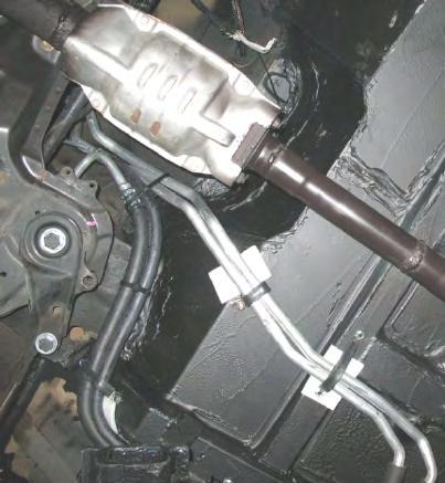
32 Fuel System Rollx Vans Charcoal Canister Vent Metal Line (3/8) # (3/8X028X13' FUSION WELD) Rollx Vans Main Fuel Metal Line (5/16) # (5/16X028/X13' FUSION) OEM Filler Neck Top (Gas Cap) OEM Fuel Fill Vent Metal Line Rollx Vans Charcoal Canister Vent Hose (3/4) # (FUEL LINE 3/4-R7) 48 inches, #12 Clamps (2) Rollx Vans Fuel Tank Vent Hose (3/4) # (FUEL LINE 3/4-R7) 48 inches, #12 Clamps (2) Rollx Vans Filler Evap Hose (3/8) #H-212 3/8 HIGH PRESSURE HOSE-R9) 48 inches, OET 17 (2) Rollx Vans 5/16 Octopus Hose #H-211 5/16 HIGH PRESSURE HOSE-R9) 48 inches, OET 15 (2) 2005 Honda Odyssey Rollx Vans Fuel / Emission System Overview (V2) OEM Charcoal Canister Vent Line OEM Charcoal Canister Rollx Vans Filler Neck #H05103ASM (FILLER NECK 2005 ASM, HONDA) Rollx Vans Main Fuel Hose (5/16) #H-211 5/16 HIGH PRESSURE HOSE-R9) 48 inches, OET 15 (2) OEM White Connectors OEM Rubber Hose Rollx OET 18 (2) OEM Fuel Pump OEM Fuel Tank OEM Tank Straps are secured with 3/8x1 bolts, washers and lock washers Page 27
 #10929-02435 (FUEL LINE 3/4-R7) 48 inches, #12 Clamps (2) Rollx VansFuel Tank Vent Hose (3/4) #10929-02435 (FUEL LINE")
 #H-212 3/8 HIGH PRESSURE HOSE-R9) 48 inches, OET 17 (2) ROLLX VANS HOSES CONNECTING TO OEM HOSES NEAR FUEL TANK")
33 Fuel System OEM Filler Neck Top (Gas Cap) OEM Fuel Fill Vent Metal Line Rollx Vans Filler Neck #H05103ASM (FILLER NECK 2005 ASM, HONDA) Rollx Vans Charcoal Canister Vent Hose (3/4) # (FUEL LINE 3/4-R7) 48 inches, #12 Clamps (2) Rollx VansFuel Tank Vent Hose (3/4) # (FUEL LINE 3/4-R7) 48 inches, #12 Clamps (2) Rollx Vans5/16 Octopus Hose #H-211 5/16 HIGH PRESSURE HOSE-R9) 48 inches, OET 15 (2) FILLER NECK AND OCTPOUS AREA Rollx Vans Filler Evap Hose (3/8) #H-212 3/8 HIGH PRESSURE HOSE-R9) 48 inches, OET 17 (2) ROLLX VANS HOSES CONNECTING TO OEM HOSES NEAR FUEL TANK Page 28


34 Fuel System OEM HOSES TOWARDS FRONT OF OEM TANK OEM SENDING UNIT (Easily Accessible Behind Rear Sofa on Left Side Under Carpet) OEM CHARCOAL CANISTER RELOCATED FRONT OF VAN Rollx Vans Aluminum Fuel Lines Page 29
35 This page was intentionally left blank. Page 30

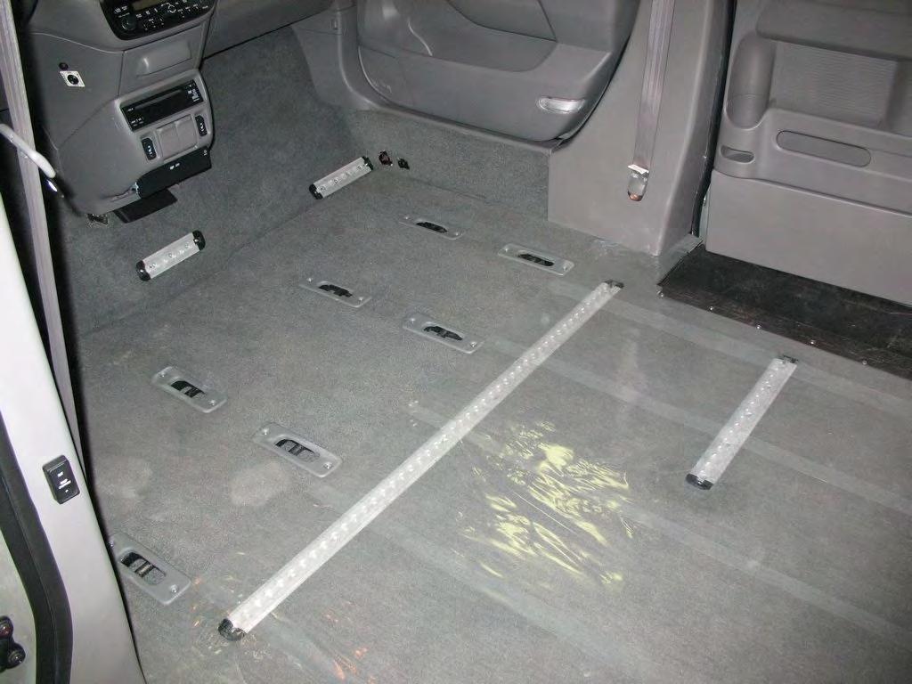
36 Interior Page 31


37 Interior Page 32
38 Kneeler Troubleshooting Symptom Possible Cause Remedy Kneel on / off switch is turned OFF. Turn kneel switch to the ON position. Van does NOT LOWER to ground while door is opening after Rollx user button is pressed. After van is lowered to ground the kneeler makes a loud ratcheting sound. Van will NOT RAISE when ramp is stowed. Van raises and while door closing the kneeler ratchets. Kneel motor. Kneel down limit switch was not activated. Kneel on / off switch is turned OFF. Kneel motor. Kneel up limit switch is activated incorrectly. Kneel up limit switch is not activated. Review display board. Turn kneel switch to the OFF position and press OTC reset button. Temporarily operate sytem without kneel option enabled. Contact customer service. Adjust kneel down limit switch. Replace if broken. Contact customer service. Turn kneel switch to the ON position. Review display board. Manually un-kneel van, turn kneel switch to the OFF position and press OTC reset button. Contact customer service. Adjust kneel up limit switch. Replace if broken. Contact customer service. Once door is closed and van is at normal height, turn kneeling switch to the OFF position and contact customer service. Page 33
39 Kneeler Replacement Parts Item Qty. Description Part # 1 1 ACTUATOR KNEELING K2XG20-12V-08RX CONN LINK NO511-C 3 1 KNEEL CHAIN ASM 2005, HONDA 6261K534-H-ASM 3A 1 CHAIN 50 ROLLER 6261K KNEEL CHAIN SWIVEL K COTTER PIN 98338A FLANGE BRG 10FDU SPRING TORSION ASM LTR-075M-6-2ASM 8 1 SPROCKET FOR #50 CHAIN 6280K SWITCH TANG BZ-2RW80-A2 6X HCS 3/8-16 X 1YZ8 QPA PPH MS 6-32 X 1 1/2Z NYLOCK NMZ ACTUATOR GUIDE ASM K05006ASM Parts on Van 15 1 KNEEL AXLE MOUNT B BLOCK TO AXLE MOUNT BOLT BLOCK TO AXLE MOUNT NUT BLOCK TO AXLE MOUNT WASHER RATCHET REVERSIBLE * 1 SOCKET 3/8" 4PW71* 1 BOOT BLK "2005" KNEELACT * 19 1 KNEEL ASSEMBLY BASE PLATE K05100BKT-H-ASM A KNEEL2005 HONDA COMPLETE ASM #KNEEL 2005 HONDA-001 (Note: Picture is for representative purpose only as some parts are in slightly different locations on a Honda kneeler) 18 Page 34
40 One Touch System Troubleshooting Important: If OTC Board is removed, the OEM System will not operate normally unless the CAN Bus Shunt is installed. The shunt is attached to the wire harness behind the OTC board. See OTC Wiring Diagram for more information. Symptom Remedy Check that OTC ON/OFF switch is on. The power toggle switch is on the actual board. No power to One Touch Controller (OTC). OTC beeps 4 times when the user tries to run a normal open/close cycle. The van's battery is dead. The OTC display is garbled. Ensure the connections on the back of the OTC board are tight. Check the OTC main fuse (40 amp) located near the vehicles main battery. Check the OTC Board fuse (1 amp) located in the Rollx Fuse Panel behind the glove box. Reset the OTC. The reset is located on the dash by the drivers left knee or on the OTC Board. Check battery voltage. Battery is low. Turn off the OTC and charge battery. Note: The alarm will sound when the battery voltage is below 11.4 vdc. This is to prevent the OTC system from draining the battery far enough as to prevent the vehicle from starting. This level is adjustable in the board's Setup menu. Van has been sitting for an extended period of time. Charge the battery. Check the current draw by placing an ammeter in series with the negative terminal on the battery with all doors closed and engine off. The draw varies, but awake, the system should be less than.850 amps and when sleeping, less than.050 amps. Additional equipment installed will also vary these numbers. See Battery section for more information. Reset the OTC. The reset is located on the dash by the drivers left knee or on the OTC Board. Page 35

41 One Touch System Overview Page 36
42 One Touch System Overview Page 37
43 One Touch System - v8.0 Basic Interface Page 38
44 One Touch System - v8.0 Advanced Interface - Setup Page 39
45 One Touch System - v8.0 Advanced Interface - Debugger Page 40
46 One Touch System - v8.0 Advanced Interface - Debugger Page 41
47 One Touch System - v8.0 Error Codes For information about OTC Interface and how to use the Debugger, please refer to 'One Touch System - v8.0 Advanced Interace' section. Remember, in Input Test Mode, double beeps indicate the switch is on or activated and single beeps indicate that it is not. Also refer to the 'One Touch System - Relay Board Troubleshooting' for more information about the Relay Board, its Overide Switches and LED Indicator Lights. Code Description - What Caused the Code Everytime before the OTC cycles, it checks the Main Battery's voltage. If reading is below the value set in the Error 1 - Battery Low Error OTC Setup, the OTC will continue to operate, but will indicate a low battery warning. The default value is 11.5 volts. Diagnostic Tests More Information Rollx Vans recommends starting your van every 4-5 days, Perform a Draw Test allow it to run minutes to keep the battery at a Follow instuctions in 'Battery Information - Draw Test Procedure' sufficient state of charge. Section A timer is included on the OTC that will shut it off after 5 minutes UNLESS in Setup Mode. Update OTC if needed. Page 42
48 One Touch System - v8.0 Error Codes Code Error 11 - Door Control Error Diagnostic Tests Description - What Caused the Code Door Control Output failure (The OTC did not successfully control the door to open or close). The OTC did not receive the signal that the door came off the OEM Door Ajar Switch when opening or did not receive the signal that the door came off the Rollx Vans Door Open Switch when closing. Once the OTC sends the signal to open the door, it waits about 2 seconds to see if the Door Ajar Switch is not activated. If the Door Ajar Switch is still active, this message will appear. More Information Output Test Place OTC in Debug - Output Test Mode to verify OTC operates OEM B-Pillar Switch / Door On/Off the door correctly by sending signal to OEM B-Pillar Switch If off, the OEM Overhead Power Sliding Door On/Off and/or OEM Front Passenger Door Unlock Switch. Switch will prevent the door from operating from the OEM 1) Check Door Open. B-Pillar Switch. The OTC uses this switch to open or close 2) Check Door Close. the door. When off, the OTC can not control the door. 3) Check Door Unlock. Make sure the switch is on and try hitting the OEM B-Pillar 4) Check Ramp Enable. This closes a relay on the OTC Relay switch. If the door still does not work, likely an OEM issue. Board that enables the ramp to run (prevents the ramp from If OEM function works, but OTC does not check wiring. running if the door is not open, door open enables ramp enable). Input Test Place OTC in Debug - Input Test Mode to verify limits operate correctly. 1) Check Door Open (Rollx Vans Door Open Switch), by opening door all the way in Door Open. 2) Check Door Close (OEM Door Ajar Switch), by close door all the way in Door Close. Rollx Vans taps into OEM Door Ajar Switch in Lower B-Pillar (See OTC Wiring for more information). Door Unlock Switch Door must be unlocked to open. First try OEM Unlock Switch in Passenger Front Door. The OTC uses this switch to unlock all the doors before an Door Open Command is sent. If OEM Switch does not unlock doors, likely an OEM issue. If OEM functions, but OTC does not check wiring. Door Ajar Switch If the OEM Door Ajar Switch is not deactivated within 2 seconds of the start of the cycle, Door Control Error will be returned. Page 43
49 One Touch System - v8.0 Error Codes Code Error 18 - Ramp Obstacle Detection Error Diagnostic Tests Check Error Log for multiple Obstactle Detection Errors. If there are many, raise the level in Setup. Input Test Place OTC in Debug - Input Test Mode to verify limits operate correctly. 1) Check Ramp Up [Limit Switch] by operating the ramp with Power Overide Switch (ITF Ramp) or manually raising (Folding Ramp). 2) Check Ramp Down [Limit Switch] by operating the ramp with Power Overide Switch (ITF Ramp) or manually raising (Folding Ramp). Description - What Caused the Code OTC detected that the ramp may have hit an obstruction on the in or out cycle. The OTC detects an obstruction by measuring the current generated from the ramp motor. The obstruction could be something in the way or a Ramp Limit is not recognized. If this current exceeds the set limit in the OTC Setup (default is 5, scale is 1-10 with 1 being the most sensative) More Information Setup - OB Detect Level (default is 5, scale is 1-10 with 1 being the most sensative) If a Ramp Limit Switch fails, the Obstacle Detection should activate and cause an error. If the Obstacle Detection does not activate, the Ramp Watchdog Timer should. This will also cause an error (Error 27) and end the cycle. Code Description - What Caused the Code Everytime before the OTC cycles, it checks to make sure Error 23 - Neutral Status Error the van is in Park. This is for safety and can not be changed. Diagnostic Tests More Information Input Test Place OTC in Debug - Input Test Mode to verify OTC recognizes Refer to Important Item Information or OTC Wiring if the van is in Park correctly Diagram for more information about where Rollx Vans gets 1) Check Neutral by placing the van in and out of Park and this signal. listening for the double beeps from the debugger. Code Error 25 - Emergency Stop Error Diagnostic Tests Operate User Button to verify working correctly. Description - What Caused the Code Anytime a Rollx Vans User or Remote Button is pressed during an open or close cycle, the system will stop immediately. If a Hard Wired User Button is held down long enough, the OTC will think it has been pressed twice and thus, cause an error. More Information This is a safety feature and can not be changed. Page 44
50 One Touch System - v8.0 Error Codes Code Error 27 - Ramp Watchdog Error Diagnostic Tests Operate the In-The-Floor ramp with Power Overide to help determine if motor and ramp are functioning correctly. Description - What Caused the Code Once the OTC sends the signal to start running the ramp motor in or out, a timer starts. If enough time passes before the proper limit switch is activated at the end of the cycle, the OTC will return this error. This is a safety feature to limit power to the motor in case of mulitple failures. More Information Not available on Folding Ramps. Output Test Place OTC in Debug - Output Test Mode to verify OTC operates the ramp motor correctly. 1) Check Ramp Open. 2) Check Ramp Close. Input Test Place OTC in Debug - Input Test Mode to verify limits operate correctly. 1) Check Ramp Up [Limit Switch] by operating the ramp with Power Overide Switch (ITF Ramp) or manually raising (Folding Ramp). 2) Check Ramp Down [Limit Switch] by operating the ramp with Power Overide Switch (ITF Ramp) or manually raising (Folding Ramp). Several factors such as low battery, cold weather or debris can prevent the motor from operating correctly. If low battery, very cold or a bad motor, the motor may run too slow causing this watchdog to activate. Debris can also prevent the motor or ramp operating at correct speed, also causing this error. If a Ramp Limit Switch fails, the Obstacle Detection should activate and cause an error (Error 18). If the Obstacle Detection does not activate, the Ramp Watchdog Timer should. This will also cause an error. If OTC Debug Output Test does not activate the motor being tested, try the overides located on the OTC Relay Board. This will inidicate a communication problem between the One Touch Controller and One Touch Relay Board. Page 45
51 Code Error 28 - Door Watchdog Error Diagnostic Tests Operate the OEM Door with the OEM B-Pillar Switch to determine of OEM Door is functioning properly. Input Test Place OTC in Debug - Input Test Mode to verify limits operate correctly. 1) Check Door Open (Rollx Vans Door Open Switch), by opening door all the way in Door Open. 2) Check Door Close (OEM Door Ajar Switch), by close door all the way in Door Close. Rollx Vans taps into OEM Door Ajar Switch in Lower B-Pillar (See OTC Wiring for more information). One Touch System - v8.0 Error Codes Description - What Caused the Code Once the OTC sends the signal to operate the OEM Door, a timer starts. If enough time passes before the proper limit switch is activated at the end of the cycle, the OTC will return this error. More Information If OEM B-Pillar Switch is not working, try the OEM Overhead Door Switch and make sure the OEM Overhead Door On/Off Switch is on. If Door Limits function correctly and door cycles open and close okay, the issue is with the door taking too long to open or close. Check alignment or motor. Output Test Place OTC in Debug - Output Test Mode to verify OTC operates the door correctly by sending signal to OEM B-Pillar Switch If an Output is an issue, the Door Control Error (Error 11) and/or OEM Front Passenger Door Unlock Switch. will likely display. 1) Check Door Open. 2) Check Door Close. Code Error 29 - Kneeler Watchdog Error Diagnostic Tests Operate the Kneeler with Power Overide to help determine if motor is functioning correctly. Description - What Caused the Code Once the OTC sends the signal to operate the Kneeler, a timer starts. If enough time passes before the proper limit switch is activated at the end of the cycle, the OTC will return this error. More Information Reset - Esc - Kneel Up/Kneel Down Input Test Place OTC in Debug - Input Test Mode to verify limits operate correctly. 1) Check Kneel Up [Limit Switch], by raising Kneeler until switch is activated or activate switch by hand. 2) Check Kneel Down [Limit Switch], by Lowering Kneeler until switch is activated or activate switch by hand. Testing with Power Overide is preferreed since it will incidicate if Limit Switch is being properly activated by Actuator's Guide. When Kneel Actuator reaches its run limit, it will begin to ratchet making a terrible sound. This is simply the motor's clutch mechanism, is not damaging but should try and be minimized. Output Test Place OTC in Debug - Output Test Mode to verify OTC operates the Kneeler correctly. 1) Check Kneel Up. 2) Check Kneel Down. If OTC Debug Output Test does not activate the motor being tested, try the overides located on the OTC Relay Board. This will inidicate a communication problem between the One Touch Controller and One Touch Relay Board. Also a low battery, bad motor or cold weather causing the motor to run very slowly can return this error. Page 46
52 One Touch System - v8.0 Error Codes Code Error 33 - Door Ajar Error Diagnostic Tests Operate the OEM Door with the OEM B-Pillar Switch to determine of OEM Door is functioning properly. Description - What Caused the Code The OTC will not run a Cycle if the door is Ajar (Not fully opened or closed). If Ramp deployed, open door fully. If ramp stowed, fully close and latch door. More Information If OEM B-Pillar Switch is not working, try the OEM Overhead Door Switch and make sure the OEM Overhead Door On/Off Switch is on. Input Test Place OTC in Debug - Input Test Mode to verify limits operate correctly. 1) Check Door Open (Rollx Vans Door Open Switch), by opening door all the way in Door Open. 2) Check Door Close (OEM Door Ajar Switch), by close door all the way in Door Close. Rollx Vans taps into OEM Door Ajar Switch in Lower B-Pillar (See OTC Wiring for more information). Page 47
 Order #OTCV8 RELAY BD Outputs that run to Kneel and Ramp Motors LED Indicator Light")


53 One Touch System - Relay Board Troubleshooting RELAY BD OTC VERSION 2 (On Board = # or # ) Order #OTCV8 RELAY BD Outputs that run to Kneel and Ramp Motors LED Indicator Light Dip Switches Inputs that run from OTC Control Board. Pressing the Dip Switches should operate each function as shown on the board as long as the board is working properly. Remember to run the ramp, the Ramp Enable must also be pressed at the same time. Pressing a Dip Switch is the same as sending a ground to the terminal. DOWN UP RAMP MOTOR DOWN UP KNEEL MOTOR RAMP ENABLE Page 48
54 Symptom Possible Cause Remedy Ramp Troubleshooting Ramp will NOT DEPLOY after door opens automatically. Ramp will NOT STOW automatically. Door does not open ALL the way. (Door "relaxes" closed slightly so the ramp might hit the door when it deploys.) Ramp will deploy before door is all the way open. Ramp will STOP AND REVERSE mid-cycle. Ramp will start to deploy or stow then stop functioning. Door detector failure. Ramp motor not engaged. Ramp down limit switch needs adjustment to deactivate. Ramp motor. OTC program failure. OTC was reset or was inactive for too long with ramp out. Ramp motor not engaged. Ramp motor. Low voltage from the battery. Door open latch failure. Door detector failure. Obstacle is detected. Pressure on cover plate. When a Open Cycle starts, the OTC will send a command to the Honda System to unlock the doors. It then sends a second command to the Honda System to open the Right Side Sliding Door. The OTC Computer then waits two seconds and checks the Door Closed Limit Switch. If it finds it still indicates the door is closed, it assumes that a person (or and obstacle) stopped the door opening sequence. It then ends the open cycle and goes back into Idle Mode. After ten to fifteen seconds it goes back into Sleep Mode. Once the OTC knows the door has begun to open, the Door Detector counts the pulses from the door motor to indicate how far open the door is. Once enough pulses have been received the Door Detector thinks the door is open all the way and send the signal to deploy the ramp. See Door Detector Section for more information. Engage ramp motor. Refer to the "Manual Operation" section of this manual. Press Rollx user button again to unkneel van and close door. Review display on OTC board and contact customer service. Review display on OTC board and contact customer service. Press OTC reset button. Stow ramp with power override and close door manually. Reset OTC. Engage ramp motor by making sure ramp motor release is turned all the way clockwise. Test operation of motor using power override. Start vehicle or charge battery. Press OTC reset button and press Rollx user button again. Try running system again. Try running system again. See Door detector section above. Clear obstruction and press Rollx user button. Review display on OTC board and contact customer service. Ensure that there are no objects on top of cover plate. Page 49
55 Ramp Replacement Parts Item Qty. Description Part # 16 4 ROLLER, ITF RAMP PLATE N1-N1DXLA 17 1 RAMP ITF ASM N005001ASM /16-18X2 S/S FHSCS TRACK FLOOR PLATE FRONT ASM,HONDA H11016ASM 20 1 TRACK FLOOR PLATE BACK ASM,HONDA H11017ASM 21 1 TRACK EXTENSION LOWER,HONDA H ALUMINUM UNTHREADED (ACTIVATOR) 92510A PRECISION MINATURE IDLER 2483K ROLLER PLATE 2011, HONDA H /16-18 x 1 SLDR 3/ CONN LINK #35 CARBON CHRLCL LOCKING HOLE & VENT SS TORX BHCS 1/ HCS 3/8-16X2 YZ8 QPACK /4 USS F/W Z TEFLON BLOCK FOR ITF RAMP N RIVETS 97517A SPACER ROLLER CUSHIONED N /8-16 FHNyz TRACK FLOOR PLATE FRONT ASM H05017ASM 36 1 TRACK FLOOR PLATE REAR ASM H05016ASM /8 NYLON FLAT WASHER Item Qty. Description Part # 1 1 ITF ACCESS PLATE N MOTORGEARBOXITF 2008 ASM N08111ASM 1 HANDLE CHROME INSIDE* MOTORGEARBOXITF 2008* N MOTOR 6WAY SWIVEL & ITF MTR* /4-20 YZNE NYLOCK CHAINROLLERSS # TENSIONER/SPROCKETASM ITF ROLLERS CUSHIONED 22875T SS TORXBHCS 1/ FLAP ASM ITF RAMP N05014ASM 3 PRECISIONMINATURE IDLER* 2483K18 3 5/16" x 1/16" NYLNWSHR HCS 1/4-20X1 1/4 YZ8QP* /4-20 YZNE NYLOCK* SS TORXBHCS 1/ HCS1/4-20X1YZ8 QPACK /16-18 NTE JAM NYLOK HCS 1/4-20 X3/4 YZ8 QPA CHAINANCHOR N FPHMS 10-32X3/8 ZK RAMP SPRING N Page 50


56 Rear Heat & Air Page 51
57 Rear Heat & Air Page 52
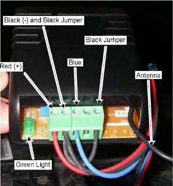
58 Remote System Troubleshooting * If remote does not work first try to operate door and ramp from any interior Rollx user button. If interior Rollx user button operates normally, see below for remote system troubleshooting Symptom Possible Cause Remedy Receiver out of range. Try remote within 10 feet of van. Sliding Door on/off switch located on left dash is turned to the OFF position. Turn switch to ON position. Door does not open when One Touch remote is pressed. Neither One Touch remote works. Remote battery is dead (No red LED light.) Remote lost its program No Power to receiver (LED light does not light up if button held for 3 seconds.) Receiver malfunction. Remove case by loosening screw on back and prying open. Replace battery with battery type A23. Make sure metal tabs are tight holding the battery. Use second remote or Rollx user button. Reprogram (relearn) remote with receiver. Check 1 Amp fuse in Rollx Fuse Holder located under glove box. If that is okay, check connections. Review display on OTC board and contact customer service. Page 53


59 Remote System Page 54
60 Seat Power and Airbags Page 55
61 Seat Power and Airbags Page 56
62 Seat Power and Airbags Page 57
63 Seat Power and Airbags Page 58

64 Seat Power and Airbags Page 59
65 Seat Power and Airbags Page 60
66 Seat Power and Airbags Page 61
67 Seat Power and Airbags Page 62
68 Seat Power and Airbags Page 63
69 Seat Power and Airbags Page 64
70 Seat Power and Airbags Page 65
71 Seat Power and Airbags Page 66
 OEM")
 #52371-TK8-A00ASM 4 ½ Drop (RIGHT)")

 REAR SUSPENSION ARM SPACER, BLOCK")

72 Suspension and Rear End UPPER SHOCK MOUNT PLATE #H05062ASM OEM DOG BONE AND BUSING (COME WITH SHOCK) OEM NUTS & BOLTS ROLLX VANS BOLTS TO WELD NU OEM Shock TRAILING ARM, (RIGHT) #52371-TK8-A00ASM 4 ½ Drop (RIGHT) #52371-TK8-A01ASM 5 ½ Drop (LEFT) #52372-TK8-A00ASM 4 ½ Drop (LEFT #52372-TK8-A00ASM 5 ½ Drop (ROLLX VANS MODIFIES) CHARCOAL CANISTER MOUNT BKT, HONDA #H05040 OEM 14 MM BOLT (4 PER) REAR SUSPENSION ARM SPACER, BLOCK #H05068 COIL PLATE WELDMENT ASM, HONDA #H05058ASM Vans built after the start date of June 21, 2012 will get the 5 ½ Drop P.N ROLLX VANS BOLT Page 67
73 This page was intentionally left blank. Page 68
74 Wiring Diagram - OTC System - vh8.0 w/ New Sec. ByPass
75 Wiring Diagram - OTC System - vh8.0 w/ New Sec. ByPass
76 Wiring Diagram - OTC System - vh8.0

77 Wiring Diagram - OTC System - vh8.0
78 Wiring - Rollx Vans Extensions to OEM - Front Left Branch Page 73

79 Wiring - Rollx Vans Extensions to OEM - Front Left Branch Page 74

80 Wiring - Rollx Vans Extensions to OEM - Front Left Branch Page 75
81 Wiring - Rollx Vans Extensions to OEM - Front Left Branch Page 76

82 Wiring - Rollx Vans Extensions to OEM - Front Left Branch Page 77

83 Wiring - Rollx Vans Extensions to OEM - Front Left Branch Page 78


84 Wiring - Rollx Vans Extensions to OEM - Front Left Branch Page 79

85 Wiring - Rollx Vans Extensions to OEM - Front Left Branch Page 80
86 Wiring - Rollx Vans Extensions to OEM - Front Left Branch Page 81

87 Wiring - Rollx Vans Extensions to OEM - Front Left Branch Page 82

88 Wiring - Rollx Vans Extensions to OEM - Front Left Branch Page 83


89 Wiring - Rollx Vans Extensions to OEM - Front Left Branch Page 84
90 Wiring - Rollx Vans Extensions to OEM - Front Left Branch Page 85
91 Wiring - Rollx Vans Extensions to OEM - Front Left Branch Page 86
92 Wiring - Rollx Vans Extensions to OEM - Front Left Branch Page 87

93 Wiring - Rollx Vans Extensions to OEM - Front Left Branch Page 88
94 Wiring - Rollx Vans Extensions to OEM - Front Right Branch Honda Overview - Floor Wire Harness (Right Front Branch) Page 89


95 Wiring - Rollx Vans Extensions to OEM - Front Right Branch #2 - Connector C 5-GRN ( ) #2 - Connector C 5-GRN ( ) Connector / Length Extended Part # Part Description Cavities / Color Location / Function Models Passenger's Under Dash Fuse Panel (C) 5-GRN Behind Right Kick Panel WIRE,16GA,GRN 1-GRN Fuse 8 Passenger EX,EX-L,TOURING WIRE,16GA, RED/YEL 2-RED/YEL Fuse 4 Passenger N/C 3-N/C WIRE,20GA,RED 4-RED Fuse 5 Passenger WIRE,20GA,BLK/WHT 5-BLK/WHT Fuse 1 Passenger Page 90
 5-BRN Behind Right Kick Panel * 0.")

96 Wiring - Rollx Vans Extensions to OEM - Front Right Branch #3 - C602 5-BRN ( ) Ref Connector / Length Extended Part # Part Description Cavities / Color Location / Function Models 3 C602 (Male) 5-BRN Behind Right Kick Panel * WIRE,12GA,WHT/BLU 1-WHT/BLU Fuse 4 - Aux Under Hood TOURING WIRE,20GA,BLU/BRN 2-BLU/BLK A/T Park Position Circuit EX,EX-L,TOURING * WIRE,12GA,WHT/BLK 3-WHT/BLK Fuse 2 - Aux Under Hood EX,EX-L,TOURING * WIRE,12GA,BLK/YEL 4-BLK/YEL Rear Window Defogger WIRE,12GA,WHT/RED 5-WHT/RED Fuse 3 - Aux Under Hood EX,EX-L,TOURING Page 91
 2005-2007 13-WHT Behind Right Kick Panel 1-GRN/YEL EVAP System 2-LT GRN EVAP System 3-BLU/YEL TPMS TOURING 4-BLU/WHT TPMS TOURING 5-BLU/BLK TPMS TOURING 6-WHT/BLK Power")
 2008-2009 20-WHT Behind Right Kick Panel 13.4 3013 WIRE,20GA,RED 1-RED EVAP System EX,EX-L,TOURING 13.")

97 Wiring - Rollx Vans Extensions to OEM - Front Right Branch #4 - C WHT ( ) #4 - C WHT ( ) Connector / Length Extended Part # Part Description Cavities / Color Location / Function Models C601 (Male) WHT Behind Right Kick Panel 1-GRN/YEL EVAP System 2-LT GRN EVAP System 3-BLU/YEL TPMS TOURING 4-BLU/WHT TPMS TOURING 5-BLU/BLK TPMS TOURING 6-WHT/BLK Power Source for PCM Sensors Circuit 7-RED EVAP System 8-YEL/BLU EVAP System N/C 9-N/C 10-WHT/RED VSA 11-WHT/BLU VSA 12-WHT F-CAN Communication Line 13-RED F-CAN Communication Line (Low) Circuit Connector / Length Extended Part # Part Description Cavities / Color Location / Function Models C601 (Male) WHT Behind Right Kick Panel WIRE,20GA,RED 1-RED EVAP System EX,EX-L,TOURING WIRE, 16GA, WHT/BLK 2-WHT/BLK Power Source for PCM Sensors Circuit N/C 3-N/C N/C 4-N/C N/C 5-N/C N/C 6-N/C N/C 7-N/C WIRE,20GA,BLUE/YLW 8-BLU/YEL TPMS TOURING WIRE,20GA,BLU/WHT 9-BLU/WHT TPMS TOURING WIRE,20GA,BLU/BRN 10-BLU/BLK TPMS TOURING 0 11-WHT/GRN 0 12-WHT/BLK N/C 13-N/C WIRE,20GA,BLK 14-BLK WHT Fuse 9 - Aux Under Hood (Rarely Used) Fuse 10 - Aux Under Hood (Rarely Used) (Ground for PCM Sensors (SG4) Circuit Reference Voltage for PCM Sensors (VCC4) Circuit EX,EX-L,TOURING EX-L TOURING EX-L TOURING EX,EX-L,TOURING EX,EX-L,TOURING WIRE,20GA,GRN 16-LT GRN EVAP System EX,EX-L,TOURING 0 17-WHT/BLU VSA EX,EX-L,TOURING 0 18-WHT-RED VSA EX,EX-L,TOURING 0 19-RED VSA EX,EX-L,TOURING 0 20-WHT VSA EX,EX-L,TOURING Page 92
 8.7 2021 WIRE,20GA,BLUE/YLW 2-BLU/YEL (Tour.")
98 Wiring - Rollx Vans Extensions to OEM - Front Right Branch #5 - C WHT ( ) Connector / Length Extended Part # Part Description Cavities / Color Location / Function Models C504 (Male) 22-WHT Behind Right Kick Panel WIRE,20GA,PINK/WHT 1-PNK (Tour. = BLU/RED) WIRE,20GA,BLUE/YLW 2-BLU/YEL (Tour. BLU/ORN) Audio System Rear Right Speaker (Extends Pink Wire - Pnk/Wht used to tell that it is different than other pink wire in harness) Audio System Rear Right Speaker EX,EX-L,TOURING EX,EX-L,TOURING 0 3-YEL Seat Heaters EX-L,TOURING 0 4-GRN/YEL Seat Heaters EX-L,TOURING WIRE,20GA,GRN 5-GRN HVAC EX,EX-L,TOURING 6-GRY/RED Seat Heaters EX-L,TOURING 7-GRY Seat Heaters EX-L,TOURING 8-N/C WIRE,20GA,GRN 9-GRN Back Up Lights Circuit EX-L,TOURING 0 10-RED/BLU Power Door Locks/Keyless Entry/Security System WIRE, 14GA, WHT/BLK 11-WHT/BLK Fuse 16 Under Hood 0 12-GRN 0 13-RED Ex=Backup Lights. EX-L, Touring = Active Noise Cancellation System Active Noise Cancellation System EX-L,TOURING 14-N/C 0 15-WHT Fuse 10 Drivers 16-GRN/ORN SRS 17-N/C 18-N/C WIRE, 20GA YEL/BLU 19-YEL/BLU Power Sliding Doors EX,EX-L,TOURING WIRE,20GA,PINK 20-PNK Power Sliding Doors EX,EX-L,TOURING WIRE,20GA,RED/WHT 21-RED/WHT Power Sliding Doors EX,EX-L,TOURING WIRE,20GA,LT GRN 22-LT GRN Power Sliding Doors EX,EX-L,TOURING Page 93
 2005-2006 13-WHT Under Front Passenger Seat 1-BRN Ground G651 2-ORN or BLU SRS 3-BLU SRS 4-WHT Fuse 10")
 Connector / Length Extended Part # Part Description")

 2008-2009 13-WHT Under Front Passenger Seat 0 1-WHT/BLK Fuse 10 Auxiliary Under Hood EX-L,TOURING N/C 2-N/C 2.")

99 Wiring - Rollx Vans Extensions to OEM - Front Right Branch #6 - C WHT ( ) Connector / Length Extended Part # Part Description Cavities / Color Location / Function Models C931 (Female) WHT Under Front Passenger Seat 1-BRN Ground G651 2-ORN or BLU SRS 3-BLU SRS 4-WHT Fuse 10 Drivers 5-BRN Ground G651 6-BRN Ground G651 EX,EX-L,TOURING 7-GRN/ORN SRS 8-WHT Fuse 10 Drivers 9-PNK/BLU SRS 10-GRN/ORN SRS 11-BLK Ground G GRN/YEL Seat Heaters EX,EX-L,TOURING 13-YEL Seat Heaters EX,EX-L,TOURING #6 - C WHT (2007) Connector / Length Extended Part # Part Description Cavities / Color Location / Function Models C931 (Female) WHT Under Front Passenger Seat 1-WHT Fuse 10 Drivers 2-WHT Fuse 10 Drivers 3-ORN or BLU SRS 4-BLU SRS 5-BRN G651 Ground EX-L,TOURING N/C 6-N/C 7-GRN/ORN SRS 8-GRN/ORN SRS 9-PNK/BLU SRS 10-BRN G651 Ground 11-GRN/YEL Seat Heaters EX-L,TOURING 12-YEL Seat Heaters EX-L,TOURING #6 - C WHT ( ) Connector / Length Extended Part # Part Description Cavities / Color Location / Function Models C931 (Female) WHT Under Front Passenger Seat 0 1-WHT/BLK Fuse 10 Auxiliary Under Hood EX-L,TOURING N/C 2-N/C WIRE,20GA,BRN 3-BRN G651 Ground 0 4-GRN/YEL Seat Heaters EX-L,TOURING 0 5-GRN/ORN SRS 0 6-ORN or BLU SRS 0 7-BLK G651 Ground EX-L,TOURING WIRE,20GA,BRN 8-BRN G651 Ground N/C 9-N/C 0 10-YEL Seat Heaters EX-L,TOURING 0 11-WHT Fuse 10 Drivers 0 12-BLU SRS 0 13-WHT/GRN Fuse 9 Auxiliary Under Hood EX-L,TOURING Page 94
 16-GRY Right Sliding Door Sill Cut 2009 WIRE,20GA,BLK 7-BLK Cut to Ground G651 EX,EX-L,TOURING")
100 Wiring - Rollx Vans Extensions to OEM - Front Right Branch #13 C GRY ( ) Rollx Vans only cuts one wire and attaches to Chassis Ground Connector / Length Extended Part # Part Description Cavities / Color Location / Function Models C782 (Male) 16-GRY Right Sliding Door Sill Cut 2009 WIRE,20GA,BLK 7-BLK Cut to Ground G651 EX,EX-L,TOURING Page 95
 8-GRY Right Sliding Door Sill Cut 1-BLK Cut to Ground G651 10 2047 WIRE,20GA,YEL 2-YEL 10 3025 WIRE,20GA,YEL/BLK 3-YEL/BLK 10 2007 WIRE,16GA,BLK/RED 4-BLK/RED Power Door")

101 Wiring - Rollx Vans Extensions to OEM - Front Right Branch #14 C781 8-GRY ( ) Connector / Length Extended Part # Part Description Cavities / Color Location / Function Models C781 (Female) 8-GRY Right Sliding Door Sill Cut 1-BLK Cut to Ground G WIRE,20GA,YEL 2-YEL WIRE,20GA,YEL/BLK 3-YEL/BLK WIRE,16GA,BLK/RED 4-BLK/RED Power Door Locks/Keyless Entry/Security System Power Door Locks/Keyless Entry/Security System Cut in Middle and Exteded. Power Door Locks/Keyless Entry/Security System WIRE, 20GA YEL/BLU 5-YEL/BLU Fuse 25 Drivers WIRE,16GA BLU/ORN 6-BLU/ORN Power Windows Cut 2009 WIRE,20GA,BLK 7-BLK Cut to Ground G WIRE, 20GA BRN/YEL 8-BRN/YEL Power Windows EX,EX-L,TOURING Page 96
Service Bulletin Power Sliding Door Operation and Troubleshooting (Replaces , Power Sliding Door Problems, dated April 20, 1999)
") Service Bulletin 01-051 Applies To: 1999 2001 Odyssey ALL May 8, 2001 Power Sliding Door Operation and Troubleshooting (Replaces 99-027, Power Sliding Door Problems, dated April 20, 1999) BACKGROUND The
Service Bulletin 01-051 Applies To: 1999 2001 Odyssey ALL May 8, 2001 Power Sliding Door Operation and Troubleshooting (Replaces 99-027, Power Sliding Door Problems, dated April 20, 1999) BACKGROUND The
Owner s Manual (Keep in glove compartment for quick reference) Honda Version 1.8
 Honda Version 1.8") Owner s Manual (Keep in glove compartment for quick reference) 2005-2010 Honda Version 1.8 Table of Contents Introduction...1 Warranty Procedures...2 Preventative Maintenance...4 Basic Operation...6 Electronic
Owner s Manual (Keep in glove compartment for quick reference) 2005-2010 Honda Version 1.8 Table of Contents Introduction...1 Warranty Procedures...2 Preventative Maintenance...4 Basic Operation...6 Electronic
Owner s Manual. (Keep in glove compartment for quick reference) Rollx Vans Power Door Vans v1.3
 Rollx Vans Power Door Vans v1.3") Owner s Manual (Keep in glove compartment for quick reference) Rollx Vans Power Door Vans v1.3 Table Of Contents Warranty Procedures.................. 4 Warranty Coverage.................... 5 Preventative
Owner s Manual (Keep in glove compartment for quick reference) Rollx Vans Power Door Vans v1.3 Table Of Contents Warranty Procedures.................. 4 Warranty Coverage.................... 5 Preventative
2001 Dodge Durango ACCESSORIES & EQUIPMENT' 'Anti-Theft Systems - Dakota & Durango 2001 ACCESSORIES & EQUIPMENT
 DESCRIPTION VEHICLE THEFT SECURITY SYSTEM 2001 ACCESSORIES & EQUIPMENT Anti-Theft Systems - Dakota & Durango Vehicle Theft Security System (VTSS) provides perimeter protection against unauthorized use
Advanced Remote Vehicle Starting System
 INSTALLATION GUIDE 1600 Advanced Remote Vehicle Starting System 1600M AUTOMATIC AND MANUAL TRANSMISSION MODELS WWW.ULTRASTARTERS.COM See website for a full size printable version of this manual. WARNING!!
POWER LOCK SYSTEMS 8P - 1 POWER LOCK SYSTEMS TABLE OF CONTENTS
 AN POWER LOCK SYSTEMS 8P - 1 POWER LOCK SYSTEMS TABLE OF CONTENTS page GENERAL INFORMATION INTRODUCTION...1 POWER LOCK SYSTEM...1 REMOTE KEYLESS ENTRY SYSTEM...1 DESCRIPTION AND OPERATION CENTRAL TIMER
INSTALLATION GUIDE Table of Contents
 CT-3100 Automatic transmission remote engine starter systems. What s included..2 INSTALLATION GUIDE Table of Contents Door lock toggle mode..... 4 Notice...2 Installation points to remember. 2 Features..2
MEGA 462 REMOTE CONTROL AUTO ALARM SYSTEM INSTALLATION & OPERATION INSTRUCTIONS WIRING DIAGRAM. White. H1 5 Pin White. H6 2 Pin White.
 MEGA 462 REMOTE CONTROL AUTO ALARM SYSTEM INSTALLATION & OPERATION INSTRUCTIONS WIRING DIAGRAM H7/1 Green : (-) 200mA Pulse H7 3 Pin H7/3 Blue : (-) 200mA Unlock White LED Indicator Valet Switch H6 2 Pin
DLKEK3HN INSTALLATION INSTRUCTIONS
 DLKEK3HN INDEX: INSTALLATION INSTRUCTIONS WIRING INSTRUCTIONS... PG 2-5 LED STATUS INDICATOR... PG 6 VALET/OVERRIDE BUTTON... PG 6 SHOCK SENSOR... PG 7 PROGRAMMABLE JUMPER-PINS... PG 7 PROGRAMMING REMOTE
DESCRIPTION & OPERATION
 ANTI-THEFT SYSTEM 1998 ACCESSORIES & EQUIPMENT General Motors Corp. - Anti-Theft System DESCRIPTION & OPERATION WARNING: Deactivate air bag system before performing any service operation. See AIR BAG RESTRAINT
POWER DOOR LOCKS 8P - 1 POWER DOOR LOCKS CONTENTS
 PL POWER DOOR LOCKS 8P - 1 POWER DOOR LOCKS CONTENTS POWER DOOR LOCKS... 1 REMOTE KEYLESS ENTRY... 3 POWER DOOR LOCKS INDEX INTRODUCTION... 1 DOOR LOCK MOTOR... 1 DOOR LOCK SWITCH... 1 INTRODUCTION All
Service Bulletin NO. 9 NO. 3
 Service Bulletin 04-052 Applies To: 2005 CR-V ALL September 3, 2004 2005 CR-V: PDI and New Model Information This service bulletin gives you the information needed for PDI of the 2005 CR-V. It also describes
2001 Honda Civic EX ACCESSORIES & EQUIPMENT' 'Cruise Control Systems - Civic & CR-V 2001 ACCESSORIES & EQUIPMENT
 DESCRIPTION 2001 ACCESSORIES & EQUIPMENT Cruise Control Systems - Civic & CR-V Cruise control system uses mechanical and electrically operated devices to maintain vehicle speed settings greater than 25
CP 634 DELUXE 4-CHANNEL KEYLESS ENTRY SYSTEM
 CP 634 DELUXE 4-CHANNEL KEYLESS ENTRY SYSTEM Installation And Operation Manual MEGATRONIX VAN NUYS, CA U.S.A. CP634 1 REMOTE CONTROL CONVENIENT SYSTEM INSTALLATION & OPERATION INSTRUCTIONS INTRODUCTION
1999 Toyota RAV ACCESSORIES & EQUIPMENT Cruise Control Systems - RAV4
 1999 ACCESSORIES & EQUIPMENT Cruise Control Systems - RAV4 DESCRIPTION WARNING: Deactivate air bag system before performing any service operation. See AIR BAG RESTRAINT SYSTEMS article. DO NOT apply electrical
FM SECURITY AND REMOTE START SYSTEM
 FM SECURITY AND REMOTE START SYSTEM INSTALLATION MANUAL BEFORE INSTALLING THIS PRODUCT PLEASE READ THIS INSTALLATION MANUAL THOROUGHLY!! This system is intended for installation on vehicles equipped with
LH POWER LOCK SYSTEMS 8P - 1 POWER LOCK SYSTEMS TABLE OF CONTENTS POWER DOOR LOCKS... 1 REMOTE KEYLESS ENTRY... 4 POWER DOOR LOCKS TABLE OF CONTENTS
 LH POWER LOCK SYSTEMS 8P - 1 POWER LOCK SYSTEMS TABLE OF CONTENTS POWER DOOR LOCKS... 1 REMOTE KEYLESS ENTRY... 4 POWER DOOR LOCKS TABLE OF CONTENTS AND POWER DOOR LOCK SYSTEM...1 CENTRAL LOCKING SYSTEM...2
GTWY515, GTWY516* Fast Idle, Shift Interlock, I/O Ford Transit Introduction
 An ISO 9001:2015 Registered Company GTWY515, GTWY516* Fast Idle, Shift Interlock, I/O 2015-2019 Ford Transit Introduction The Gateway 515 and 516 are wheelchair lift safety interlocks which allows lift
VEHICLE THEFT/SECURITY SYSTEMS
 WJ VEHICLE THEFT/SECURITY SYSTEMS 8Q - 1 VEHICLE THEFT/SECURITY SYSTEMS CONTENTS... 6 VEHICLE THEFT SECURITY SYSTEM... 1 VEHICLE THEFT SECURITY SYSTEM INDEX AND DOOR AJAR SWITCH... 3 DRIVER CYLINDER LOCK
INSTALLATION GUIDE. FCC ID NOTICE
 REV.5 RS. ADVANCED REMOTE STARTER INSTALLATION GUIDE www.security.soundstream.com FCC ID NOTICE This device complies with Part 5 of the FCC rules. Operation is subject to the following conditions:. This
2002 Dodge Intrepid ES ACCESSORIES & EQUIPMENT Anti-Theft Systems - Concorde, Intrepid & 300M
 DESCRIPTION SENTRY KEY IMMOBILIZER SYSTEM 2002-03 ACCESSORIES & EQUIPMENT Anti-Theft Systems - Concorde, Intrepid & 300M CAUTION: Large metallic objects, or items such as magnetic pass-keys, may cause
Towing and Road Service Guide For Lexus LS 600h L. Quality and Education Services AAA Automotive 1000 AAA Drive Heathrow, FL 32746
 Towing and Road Service Guide For Lexus LS 600h L Quality and Education Services AAA Automotive 1000 AAA Drive Heathrow, FL 32746 June 15, 2007 Index General Towing Information Special Precautions 3 Hybrid
TWO-WAY LED AUTOMATIC TRANSMISSION REMOTE STARTER. User Guide WARNING
 TWO-WAY LED AUTOMATIC TRANSMISSION REMOTE STARTER User Guide WARNING It is the responsibility of the vehicle operator to ensure their vehicle is parked in a safe and responsible manner. 1. When leaving
Remote Start with Keyless Entry Installation Guide CA 5051
 PROFESSIONAL SERIES Remote Start with Keyless Entry Installation Guide CA 5051 2010 Audiovox Electronics Corporation. All rights reserved. 1 Table of Contents Before You Begin... 3 Wire Connection Guide...
HL515-B Fast Idle, Lift Interlock Ford Transit
 An ISO 9001:2008 Registered Company HL515-B Fast Idle, Lift Interlock 2015-2018 Ford Transit Introduction The HighLock 515-B is a wheelchair lift safety interlock which will only work with the ignition
SUNROOF - SERVICE INFORMATION ADJUSTMENTS
 SUNROOF - SERVICE INFORMATION DESCRIPTION OPERATION DIAGNOSIS AND TESTING POWER TOP - SUNROOF SUNROOF ASSEMBLY-MODULE REMOVAL INSTALLATION CHANNEL-DRAIN REMOVAL INSTALLATION COVER-GUIDE MECHANISM REMOVAL
MEGA WAY LCD 4-CHANNEL CAR ALARM SECURITY SYSTEM. Installation Manual MEGATRONIX CALIFORNIA, USA MEGA 2500 INSTALL 1
 MEGA 2500 2-WAY LCD 4-CHANNEL CAR ALARM SECURITY SYSTEM Installation Manual MEGATRONI CALIFORNIA, USA MEGA 2500 INSTALL 1 MEGA 2500 INSTALL 2 INSTALLATION DIAGRAM H8: 10 Pin White Mini Connector H8 10
U S A INSTALLATION GUIDE EP400 / E8-B
 U S A INSTALLATION GUIDE EP400 / E8-B www.easycar-.com Before Beginning the Installation 1. Wire Connection Guides Please read this entire installation guide before beginning the installation. The installation
Model PRO-9775T Owner's Manual 4 Button Remote Start Security System With Plug-In Shock Sensor & Starter Disable
 Model PRO-9775T Owner's Manual 4 Button Remote Start Security System With Plug-In Shock Sensor & Starter Disable FEATURES:! 2 Four Button Programmable RF Transmitters! Four Channel Code Learning Receiver
KE 680 DELUXE 4-CHANNEL KEYLESS ENTRY SYSTEM DOOR LOCK RELAYS ON-BOARD. Installation And Operation Manual MEGATRONIX CALIFORNIA, U.S.A.
 KE 680 DELUE 4-CHANNEL KEYLESS ENTRY SYSTEM DOOR LOCK RELAYS ON-BOARD Installation And Operation Manual MEGATRONI CALIFORNIA, U.S.A. KE 680 1 INSTALLATION DIAGRAM H8: 10 Pin White Mini Connector H8 10
GTWY605 Fast Idle, Shift Interlock, I/O Chevy 610 Van - 6.0L and 6.6L Engines Contact InterMotive for additional vehicle applications.
 An ISO 9001:2008 Registered Company GTWY605 Fast Idle, Shift Interlock, I/O 2009-2017 Chevy 610 Van - 6.0L and 6.6L Engines Contact InterMotive for additional vehicle applications. Introduction The Gateway
2001 Chevrolet Corvette ACCESSORIES & EQUIPMENT Remote Keyless Entry Systems - Corvette
 DESCRIPTION 2001 ACCESSORIES & EQUIPMENT Remote Keyless Entry Systems - Corvette Remote Keyless Entry (RKE) system is controlled by Remote Function Actuation (RFA) system. Transmitter allows remote control
Model PRO-9675FT4 Owner's Manual
 Model PRO-9675FT4 Owner's Manual 4 Button Remote Start Security System With Plug-In Shock Sensor & Starter Disable FEATURES : w 2 Four Button Programmable RF Transmitters w Four Channel Code Learning Receiver
TWO-WAY LED MANUAL / AUTOMATIC TRANSMISSION REMOTE STARTER. User Guide WARNING
 TWO-WAY LED MANUAL / AUTOMATIC TRANSMISSION REMOTE STARTER User Guide WARNING It is the responsibility of the vehicle operator to ensure their vehicle is parked in a safe and responsible manner. 1. a)
GTWY505 Fast Idle, Shift Interlock, I/O Ford E-Series
 An ISO 9001:2008 Registered Company GTWY505 Fast Idle, Shift Interlock, I/O 2009-2018 Ford E-Series Introduction The Gateway 505 is a wheelchair lift safety interlock which will only work with the ignition
Vehicle Rear Observation System With Integrated Parking Sensors
 Vehicle Rear Observation System With Integrated Parking Sensors Model: CAMSBAR Installation/User Manual Features: 2.5" LCD Color Display 2 Ultra Sonic Rear Obstacle Sensors On-screen Display Function Automatically
Special Tool Required: MPCS Service Connector 07WAZ A
 Special Tool Required: MPCS Service Connector 07WAZ-001010A 1. Check the No.9 and 13 passenger fuses. Are the fuses OK? YES -Go to step 2. NO -Find and repair the cause of the blown fuse. 2. Test power
INSTALLATION MANUAL. Model: PLUS For Technical Assistance, please call (800) , or visit
 , or visit") R Vehicle Security INSTALLATION MANUAL Model: PLUS-4700 This device complies with part 15 of the FCC rules. Operation is subject to the following two conditions: (1) This device may not cause harmful interference;
R Vehicle Security INSTALLATION MANUAL Model: PLUS-4700 This device complies with part 15 of the FCC rules. Operation is subject to the following two conditions: (1) This device may not cause harmful interference;
Covers All 35xx Series Advanced 2-Way Remote Starters. Technical Support: ext 0
 INSTALL GUIDE Covers All 35xx Series Advanced 2-Way Remote Starters www.ultrastarters.com Technical Support: 866-698-5872 ext 0 support@ultrastarters.com Warning!! The system must be placed into Service
TWO-WAY LED MANUAL TRANSMISSION REMOTE STARTER. User Guide WARNING
 TWO-WAY LED MANUAL TRANSMISSION REMOTE STARTER User Guide WARNING It is the responsibility of the vehicle operator to ensure their vehicle is parked in a safe and responsible manner. 1. When leaving the
Main Harness Quantity: 1
 Smart Engine Start INSTALLATION MANUAL Genuine Part # : H001SVA900 Vehicle Model : WRX Kit Contents Service P/N: H001SVA910 Service P/N: H001SVA820 NOT USED NOT USED SES ECU Quantity: 1 Double-sided tape
Installation & Service Manual
 Installation & Service Manual for M² Sync Slideout Control Box #1510000122 CONTENTS Introduction Installation Installation Problems Program Mode Operation Mode Preventative Maintenance Fault Diagnostics
The parking brake is an electrically actuated system that operates drum brakes integrated into the rear brake discs. The
 Page 1 of 15 Published: Oct 22, 2004 Parking Brake COMPONENT LOCATIONS Item Part Number Description 1 Clutch pedal position sensor (manual transmission models only) 2 Parking brake indicators (all except
REC-11+ REMOTE RECEIVER UNIT
 Resetting The Programmable Features The installer may quickly and easily return all 17 programmable features back to the factory settings. Changing individual features were explained in detail in the previous
e-ask electronic Access Security Keyless-entry
 e-ask electronic Access Security Keyless-entry Multiplex System Multiplex System Installation & Instructions (UM15 ~ 22272-03) Table of Contents Introduction... 1 Standard e-fob Operation and Features...
6R / 5-BUTTON SERIES VEHICLE SECURITY SYSTEM
 6R / 5-BUTTON SERIES VEHICLE SECURITY SYSTEM Button 1 Button 2 Button 5 Button 3 Button 4 Standard Features: Two 5-Button Remote Transmitters Status indicator (LED) Valet / override switch Multi-tone siren
G - TESTS W/CODES - 2.2L
 G - TESTS W/CODES - 2.2L 1994 Toyota Celica 1994 ENGINE PERFORMANCE Toyota 2.2L Self-Diagnostics Celica INTRODUCTION If no faults were found while performing F - BASIC TESTING, proceed with self-diagnostics.
SECTION Multifunction Electronic Modules
 419-10-i Multifunction Electronic Modules 419-10-i SECTION 419-10 Multifunction Electronic Modules CONTENTS PAGE DIAGNOSIS AND TESTING Smart Junction Box (SJB)... 419-10-2 Principles of Operation... 419-10-2
Sofa Slideout Assembly OWNER'S MANUAL. Rev: Page 1 Sofa Slideout Owners Manual
 Sofa Slideout Assembly OWNER'S MANUAL Rev: 06.14.2016 Page 1 Sofa Slideout Owners Manual TABLE OF CONTENTS Warning, Safety, and System Requirement Information 3 Product Information 3 Prior to Operation
INSTALLATION MANUAL. Remote Mobile Security System. Model: PL30
 Remote Mobile Security System INSTALLATION MANUAL Model: PL30 Copyright 1998 Magnadyne Corporation For Technical Assistance (800) 638-3600 For Fax on Demand Technical Assistance (800) 994-9977 (Must be
Model 700T Installation Guide
 Model 700T Installation Guide 2001 Directed Electronics, Inc. Vista, CA N700T 8-01 Rev. E 1.1 table of contents What Is Included...................... 3 Installation Points to Remember............ 3 Before
"WE'VE GOT THE EDGE ON SECURITY" INSTALLATION MANUAL AL-700 ATV / AL-900 ATV / AL-1000 ATV
 "WE'VE GOT THE EDGE ON SECURITY" INSTALLATION MANUAL AL-700 ATV / AL-900 ATV / AL-1000 ATV COPYRIGHT: OMEGA RESEARCH & DEVELOPMENT INC. 1997 Contents 5 WIRE HARNESS CONNECTIONS Black Wire (Chassis Ground)...
An ISO 9001:2015 Registered Company
 Introduction An ISO 9001:2015 Registered Company HL550-B Fast Idle, Lift Interlock 2011-2016 Ford F250-F550 2017-2019 Ford F250-F550 (B-HL550*) 2016-2017 Ford F650/750** *Uses the Ford 24-Pin Data Link
Automatic / Manual Transmission Remote Start with Keyless Entry Installation Guide for models: ca5153 ca5153sst
 PROFESSIONAL SERIES Automatic / Manual Transmission Remote Start with Keyless Entry Installation Guide for models: ca5153 ca5153sst 2012 Audiovox Electronics Corporation. All rights reserved. 1 Table of
Battery Tester. GxT Incorporated, Cheboygan MI, U.S.A. All Rights Reserved E040-01G. 40 & 42HD Operator s Manual
 Battery Tester GxT Incorporated, Cheboygan MI, U.S.A. All Rights Reserved E040-01G 40 & 42HD Operator s Manual SPECIFICATIONS Measurement Range...Ferret 40... Ferret 42HD Battery Volts... 4.0 to 19.99...
SECTION Interior Lighting
 417-02-i Interior Lighting 417-02-i SECTION 417-02 Interior Lighting CONTENTS PAGE DIAGNOSIS AND TESTING Interior Lighting... 417-02-2 Principles of Operation... 417-02-2 Inspection and Verification...
Service Bulletin Immobilizer System (Type 6) (Supersedes , dated February 20, 2009; see REVISION SUMMARY) February 22, 2013
 (Supersedes , dated February 20, 2009; see REVISION SUMMARY) February 22, 2013") Service Bulletin 06-033 Applies To: 2007-09 MDX ALL 2007-12 RDX ALL February 22, 2013 Immobilizer System (Type 6) (Supersedes 06-033, dated February 20, 2009; see REVISION SUMMARY) REVISION SUMMARY This
Service Bulletin 06-033 Applies To: 2007-09 MDX ALL 2007-12 RDX ALL February 22, 2013 Immobilizer System (Type 6) (Supersedes 06-033, dated February 20, 2009; see REVISION SUMMARY) REVISION SUMMARY This
INSTALLATION MANUAL. Model: PLUS Vehicle Security
 R Vehicle Security INSTALLATION MANUAL Model: PLUS-5000 Copyright 1999 Magnadyne Corporation For Technical Assistance (800) 638-3600 For Fax on Demand Technical Assistance (800) 994-9977 (Must be a Registered
Remote Start with Keyless Entry Installation Guide ca5054
 PROFESSIONAL SERIES Remote Start with Keyless Entry Installation Guide ca5054 2014 Voxx Electronics Corporation. All rights reserved. 1 Table of Contents Before You Begin...3 Wire Connection Guide...4
 Page 1 of 29 Section 04-05: Suspension, Computer Controlled 1997 Town Car Workshop Manual DIAGNOSIS AND TESTING Procedure revision date: 05/16/2000 Suspension, Computer Controlled Inspection and Verification
C802/C802D/C802TD/C820 Alternators Troubleshooting Guide
 C802/C802D/C802TD/C820 Alternators Troubleshooting Guide Hazard Definitions These terms are used to bring attention to presence of hazards of various risk levels or to important information concerning
Power Sliding Door (PSD) Diagnostic Approach. Fixing Intermittent Malfunctions. Power Sliding Door (PSD) Diagnostic Information
 Diagnostic Approach. Fixing Intermittent Malfunctions. Power Sliding Door (PSD) Diagnostic Information") Power Sliding Door (PSD) Diagnostic Information Power Sliding Door (PSD) The power sliding door (PSD) provides built-in diagnostics. This assists the service technicians during troubleshooting. The PSD
Power Sliding Door (PSD) Diagnostic Information Power Sliding Door (PSD) The power sliding door (PSD) provides built-in diagnostics. This assists the service technicians during troubleshooting. The PSD
Model 2100 Installation Guide
 Model 2100 Installation Guide 2001 Directed Electronics, Inc. Vista, CA N2100 4-01 Rev. N/C 1.1 table of contents What Is Included..................... 2 Wiring Quick Reference Guide............ 3 Primary
Roll Up Door Operator
 INSTRUCTIONS & OWNERS MANUAL Roll Up Door Operator 2 INDEX Preparation before installation 4. Terms and definitions 5. Pictures & names of parts 6. Mounting the weight bar 7. Installing the operator 7.
NOTE. Installation and Service Manual Dual Planetary Gearmotor Slim Rack Slide Out System
 Installation & Service Manual Slim Rack In-Wall Slide Out System Control Box Part Number 1510000199 Content Copyright LCI/Power Gear Issued: December 2014 #3010002588, Rev. 0E Installation and Service
INSTALLATION INSTRUCTIONS DODGE DAKOTA 2 KIT # 682 (2WD), 692 (4WD) 3 KIT # 683 (2WD), 693 (4WD)
, 692 (4WD) 3 KIT # 683 (2WD), 693 (4WD)") INSTALLATION INSTRUCTIONS 1997-1999 DODGE DAKOTA 2 KIT # 682 (2WD), 692 (4WD) 3 KIT # 683 (2WD), 693 (4WD) Installation of a Performance Accessories body lift kit will change the vehicle s center of gravity
INSTALLATION INSTRUCTIONS 1997-1999 DODGE DAKOTA 2 KIT # 682 (2WD), 692 (4WD) 3 KIT # 683 (2WD), 693 (4WD) Installation of a Performance Accessories body lift kit will change the vehicle s center of gravity
" MANUALLY OVERRIDING YOUR SYSTEM
 Model PRO 2000aS Owner s Manual 3 Button Remote Security System with Keyless Entry IMPORTANT! In order to provide the highest possible level of security to your vehicle, this system is equipped with selectable
ADD-ON REMOTE STARTER TO AFTERMARKET SYSTEM
 MEGATRONIX RS 110 ADD-ON REMOTE STARTER TO AFTERMARKET SYSTEM Installation and Operation Manual MEGATRONIX CHATSWORTH, CA U.S.A. RS110 ADD-ON REMOTE CAR STARTER For Vehicles Equipped With Automatic Transmission
Service Bulletin Immobilizer System (Type 7) February 22, (Supersedes , dated March 6, 2009; see REVISION SUMMARY)
 February 22, (Supersedes , dated March 6, 2009; see REVISION SUMMARY)") Service Bulletin 09-016 Applies To: See VEHICLES AFFECTED February 22, 2013 Immobilizer System (Type 7) (Supersedes 09-016, dated March 6, 2009; see REVISION SUMMARY) REVISION SUMMARY This service bulletin
Service Bulletin 09-016 Applies To: See VEHICLES AFFECTED February 22, 2013 Immobilizer System (Type 7) (Supersedes 09-016, dated March 6, 2009; see REVISION SUMMARY) REVISION SUMMARY This service bulletin
Elite Power Solutions Automatic Battery Control (ABC) Operation Manual
 Operation Manual") Elite Power Solutions Automatic Battery Control (ABC) Operation Manual Elite Power Solutions 335 E Warner Rd. STE 3 Chandler, AZ 85225 www.elitepowersolutions.com ABC Operation Manual Page 1 Table of Contents
Elite Power Solutions Automatic Battery Control (ABC) Operation Manual Elite Power Solutions 335 E Warner Rd. STE 3 Chandler, AZ 85225 www.elitepowersolutions.com ABC Operation Manual Page 1 Table of Contents
COMMANDO REMOTE CONTROL ENGINE STARTER. Limited Warranty Statement MADE IN THE U.S.A. IMPORTANT KEEP YOUR INVOICE WITH THIS WARRANTY STATEMENT!
 Limited Warranty Statement GNU COMMANDO LINE WARRANTY STATEMENT GNU warrants this product to be free from defects in material and workmanship for a period of one (1) year from the date of sale to the original
AUTOMATIC TRANSMISSION ONLY! Technical Support: ext 1 Warning!!
 REV.2006.04 INSTALL GUIDE AUTOMATIC TRANSMISSION ONLY! www.ultrastarters.com Technical Support: 877-598-2100 ext 1 support@ultrastarters.com Warning!! The system must be placed into Service Mode before
INSTALLATION INSTRUCTIONS
 INSTALLATION INSTRUCTIONS Accessory REMOTE CONTROL Application 2011 ODYSSEY (EXCEPT LX) Publications No. AII 43923 Issue Date SEP 2010 PARTS LIST Remote Control Engine Starter Unit Kit P/N 08E91-E22-101A
BOLT-ON AND WELD-ON FLUSH FLOOR SLIDEOUT SYSTEMS OPERATION AND SERVICE MANUAL
 BOLT-ON AND WELD-ON FLUSH FLOOR SLIDEOUT SYSTEMS OPERATION AND SERVICE MANUAL TABLE OF CONTENTS SYSTEM...... Warning........ Description...... Prior to Operation OPERATION... Main Components... Mechanical...
Door Locks LOCK THE VEHICLE AND SET THE ALARM
 Door Locks LOCK THE VEHICLE AND SET THE ALARM All doors can be centrally locked and unlocked remotely, using the key transmitter buttons. Only the driver s door is equipped with an external key lock, which
An ISO 9001:2008 Registered Company
 Introduction An ISO 9001:2008 Registered Company GTWY506 Fast Idle, Shift Interlock, I/O 2011-2016 Ford F250-F550 2017 Ford F250-F550 (Uses the Ford 24-Pin Data Link Harness) 2016-2017 Ford F650/750* *Transmission
Model AS-9234E. Owners Guides
 Model AS-9234E Owners Guides This unit is capable of 3 installation methods. Select the guide for your customer that matches the installation in their particular vehicle. PATENTED: www.voxxintlcorp.com/company/patents
K9-Mundial-2. ver. a color cover. Owner's Guide & Installation Instructions. MA_K9-Mundial-2/REV0 4/01 COPYRIGHT: OMEGA RESEARCH & DEVELOPMENT 2001
 K9-Mundial-2 NOTE: This is a place marker cover ver. The production unit has a color cover ver. Owner's Guide & Installation Instructions MA_K9-Mundial-2/REV0 4/01 COPYRIGHT: OMEGA RESEARCH & DEVELOPMENT
Model APS-20B Owner's Manual
 Model APS-20B Owner's Manual 3 Button Vehicle Alarm System With Auxiliary Output FEATURES: 2 Three Button RF Transmitters Three Channel Code Learning Receiver Remote Panic In All Modes Built-In Parking
RS-230-DP. Operation Guide
 RS-230-DP Deluxe Keyless Entry & Remote Start July 27, 2010 Operation Guide Temporary cover. Color cover is in a separate file. Table Of Contents Introduction...2 The Transmitter...3 Transmitter Functions...3
2 WAY REMOTE STARTER & ALARM SYSTEM INSTALLATION GUIDE FCC ID NOTICE
 REV. ARS. WAY REMOTE STARTER & ALARM SYSTEM INSTALLATION GUIDE FCC ID NOTICE This device complies with Part 5 of the FCC rules. Operation is subject to the following conditions:. This device may not cause
2010 Flex Workshop Manual. REMOVAL AND INSTALLATION Procedure revision date: 12/10/2010
 SECTION 501-12: Instrument Panel and Console REMOVAL AND INSTALLATION Procedure revision date: 12/10/2010 Refrigerator Rear console Item Part Number Description 1 04567 Front finish panel 2 045A90B Bottom
Model K20 installation guide. ProSecurity
 Model K20 installation guide ProSecurity NOTE: This product is intended for installation by a professional installer only! Any attempt to install this product by any person other than a trained professional
INSTALLATION MANUAL. Remote Mobile Security System. Model: PL50
 Remote Mobile Security System INSTALLATION MANUAL Model: PL50 Copyright 2000 Magnadyne Corporation For Technical Assistance (800) 638-3600 For Fax on Demand Technical Assistance (800) 994-9977 (Must be
12V/25A BATTERY CHARGER MAINTAINER / JUMPSTARTER
 12V/25A BATTERY CHARGER MAINTAINER / JUMPSTARTER OWNER S MANUAL Read carefully and understand all ASSEMBLY AND OPERATION INSTRUCTIONS before operating. Failure to follow the safety rules and other basic
Service Manual Gulf Stream Electronic Full Wall Slide Systems
 Service Manual Gulf Stream Electronic Full Wall Slide Systems CONTENTS Page Before you operate the slide system 2 Operating Instructions 3 Preventive maintenance 3 Manually overriding your slide system
LIPPERTCOMPONENTS, INC.
 LIPPERTCOMPONENTS, INC. SCHWINTEK INWALL SLIDEOUT SYSTEM OPERATION AND SERVICE MANUAL Contents I. Controls 1-1 System components 1 1-1A versions C1 & C2 2 1-2 Motor wiring harness connections 3 1-3 Extend
INTELLIGENT BATTERY CHARGER/MAINTAINER
 INTELLIGENT BATTERY CHARGER/MAINTAINER OWNER S MANUAL Read carefully and understand all ASSEMBLY AND OPERATION INSTRUCTIONS before operating. Failure to follow the safety rules and other basic safety precautions
Automatic / Manual Transmission Remote Start with Keyless Entry Installation Guide. ca 5152
 PROFESSIONAL SERIES Automatic / Manual Transmission Remote Start with Keyless Entry Installation Guide ca 5152 1 Table of Contents Before You Begin... 3 Wire Connection Guide... 4 11 Pin Main Harness...
INSTALLATION INSTRUCTIONS
 INSTALLATION INSTRUCTIONS Accessory REMOTE CONTROL Application 2012 ODYSSEY (EXCEPT LX) Publications No. AII 46745 Issue Date SEP 2011 PARTS LIST Remote Control Engine Starter Unit Kit P/N 08E91-E22-101A
OCT/21/02 MEGA 670L DELUXE 4-CHANNEL CAR ALARM SECURITY SYSTEM. Installation And Operation Manual MEGATRONIX CALIFORNIA, U.S.A.
 OCT/21/02 MEGA 670L DELUXE 4-CHANNEL CAR ALARM SECURITY SYSTEM Installation And Operation Manual MEGATRONIX CALIFORNIA, U.S.A. MEGA 670 1 MEGA 670 2 OCT/21/02 OCT/21/02 WIRING DIAGRAM H7: 10 Pin White
HL610-B Fast Idle, Lift Interlock Chevy 610 Van 6.0L and 6.6L Contact InterMotive for additional vehicle applications
 An ISO 9001:2015 Registered Company HL610-B Fast Idle, Lift Interlock 2009-2019 Chevy 610 Van 6.0L and 6.6L Contact InterMotive for additional vehicle applications Introduction The HighLock 610 is a wheelchair
MM1 Installation Instructions
 MM1 Installation Instructions PROFESSIONAL INSTALLATION STRONGLY RECOMMENDED Installation Precautions: Roll down window to avoid locking keys in vehicle during installation Avoid mounting components or
Model: APS-610a Owner s Manual 4 Button Remote Security System with Dual Stage Shock Sensor
 Model: APS-610a Owner s Manual 4 Button Remote Security System with Dual Stage Shock Sensor IMPORTANT! In order to provide the highest possible level of security to your vehicle, this system is equipped
Wired Real Time GPS Installation Instructions
 Wired Real Time GPS Installation Instructions This page intentionally left blank. TABLE OF CONTENTS 1. Introduction 2 2. Selecting the Mounting Location for the Device. 3 3. Mounting the Device 5 4. Optional
VEHICLE SECURITY SYSTEM INSTALLATION MANUAL
 VEHICLE SECURITY SYSTEM WITH REMOTE START & NETWORK INTERFACE INSTALLATION MANUAL BEFORE INSTALLING THIS PRODUCT PLEASE READ THIS INSTALLATION MANUAL THOROUGHLY!! Before You Begin This system is intended
Model: SE-4020-CA Automatic Battery Charger
 OWNERS MANUAL Model: SE-4020-CA Automatic Battery Charger PLEASE SAVE THIS OWNERS MANUAL AND READ BEFORE EACH USE. This manual will explain how to use the battery charger safely and effectively. Please
TWO-WAY LCD AUTOMATIC TRANSMISSION REMOTE STARTER. User Guide
 TWO-WAY LCD AUTOMATIC TRANSMISSION REMOTE STARTER User Guide A note concerning the battery inside the transmitter: Depending on your usage of the transmitter, the battery can last anywhere between 3 to
Model CSI-300 Owner s Manual
 Model CSI-300 Owner s Manual 4 Button Remote Security System with Dual Stage Shock Sensor IMPORTANT! In order to provide the highest possible level of security to your vehicle, this system is equipped
C.E. Niehoff & Co. C653/C653A and C625 Alternators Troubleshooting Guide NOTICE. Hazard Definitions. Battery Charge Volt and Amp Values
 C.E. Niehoff & Co. C653/C653A and C625 Alternators Troubleshooting Guide Hazard Definitions These terms are used to bring attention to presence of hazards of various risk levels or to important information