RPA-2 MODEL: A12950-XXX
|
|
|
- Theodore Henry
- 6 years ago
- Views:
Transcription
1 SERVICE MANUAL LN April 203 Supersedes LN RPA-2 MODEL: A2950-XXX IMPORTANT: Before using this equipment, carefully read SAFETY PRECAUTIONS, starting on page, and all instructions in this manual. Keep this Service Manual for future reference. Service Manual Price: $50.00 (U.S.)
2 LN
3 RPA-2 POWDER APPLICATOR - Contents CONTENTS PAGE SAFETY: -6 SAFETY PRECAUTIONS... HAZARDS / SAFEGUARDS INTRODUCTION: 7- GENERAL DESCRIPTION... 7 POWDER APPLICATOR MAIN COMPONENTS... 8 TOOLS REQUIRED... 9 HIGH VOLTAGE GENERATION/ROUND NOZZLE DESCRIPTION... 0 SPECIFICATIONS/CENTER OF GRAVITY... INSTALLATION: 2-3 CONNECTION PROCEDURE... 2 FUNCTION CHECK AND SCHEMATIC... 3 OPERATION: 4-5 GENERAL OPERATION/START-UP MAINTENANCE: 6-27 TROUBLESHOOTING GUIDE INSPECTING AND CLEANING APPLICATOR DIS-ASSEMBLY HIGH VOLTAGE CONTACT WIRE REPAIR APPLICATOR ASSEMBLY DEFECTIVE PARTS RECOGNITION PARTS: APPLICATOR PARTS DRAWING PARTS LIST AND DRAWINGS SHAPE AIR ASSEMBLY AND PARTS LIST ELECTRODE ASSEMBLY AND PARTS LIST SPARE PARTS WARRANTY POLICIES: 43 LIMITED WARRANTY LN
4 RPA-2 POWDER APPLICATOR Safety SAFETY SAFETY PRECAUTIONS Before operating, maintaining or servicing any Ransburg electrostatic coating system, read and understand all of the technical and safety literature for your Ransburg products. This manual contains information that is important for you to know and understand. This information relates to USER SAFETY and PRE- VENTING EQUIPMENT PROBLEMS. To help you recognize this information, we use the following symbols. Please pay particular attention to these sections. A WARNING! states information to alert you to a situation that might cause serious injury if instructions are not followed. A CAUTION! states information that tells how to prevent damage to equipment or how to avoid a situation that might cause minor injury. A NOTE is information relevant to the procedure in progress. While this manual lists standard specifications and service procedures, some minor deviations may be found between this literature and your equipment. Differences in local codes and plant requirements, material delivery requirements, etc., make such variations inevitable. Compare this manual with your system installation drawings and appropriate Ransburg equipment manuals to reconcile such differences.! W A R N I N G The user MUST read and be familiar with the Safety Section in this manual and the Ransburg safety literature therein identified. This manual MUST be read and thoroughly understood by ALL personnel who operate, clean or maintain this equipment! Special care should be taken to ensure that the WARNINGS and safety requirements for operating and servicing the equipment are followed. The user should be aware of and adhere to ALL local building and fire codes and ordinances as well as NFPA-33 SAFETY STANDARD, LATEST EDITION, prior to installing, operating, and/or servicing this equipment.! W A R N I N G The hazards shown on the following pages may occur during the normal use of this equipment. Please read the hazard chart beginning on page 2. Careful study and continued use of this manual will provide a better understanding of the equipment and process, resulting in more efficient operation, longer trouble-free service and faster, easier troubleshooting. If you do not have the manuals and safety literature for your Ransburg system, contact your local Ransburg representative or Ransburg. LN

5 RPA-2 POWDER APPLICATOR - Safety AREA Tells where hazards may occur. Spray Area HAZARD Tells what the hazard is. Fire Hazard Improper or inadequate operation and maintenance procedures will cause a fire hazard. Protection against inadvertent arcing that is capable of causing fire or explosion is lost if any safety interlocks are disabled during operation. Frequent Power Supply or Controller shutdown indicates a problem in the system requiring correction. SAFEGUARDS Tells how to avoid the hazard. Fire extinguishing equipment must be present in the spray area and tested periodically. Spray areas must be kept clean to prevent the accumulation of combustible residues. Smoking must never be allowed in the spray area. The high voltage supplied to the atomizer must be turned off prior to cleaning, flushing or maintenance. When using solvents for cleaning: Those used for equipment flushing should have flash points equal to or higher than those of the coating material. Those used for general cleaning must have flash points above 00 F (37.8 C). Spray booth ventilation must be kept at the rates required by NFPA-33, OSHA, country, and local codes. In addition, ventilation must be maintained during cleaning operations using flammable or combustible solvents. Electrostatic arcing must be prevented. Safe sparking distance must be maintained between the parts being coated and the applicator. A distance of inch for every 0KV of output voltage is required at all times. Test only in areas free of combustible material. Testing may require high voltage to be on, but only as instructed. Non-factory replacement parts or unauthorized equipment modifications may cause fire or injury. If used, the key switch bypass is intended for use only during setup operations. Production should never be done with safety interlocks disabled. Never use equipment intended for use in waterborne installations to spray solvent based materials. The paint process and equipment should be set up and operated in accordance with NFPA-33, NEC, OSHA, local, country, and European Health and Safety Norms. LN

6 RPA-2 POWDER APPLICATOR Safety AREA Tells where hazards may occur. Spray Area HAZARD Tells what the hazard is. Explosion Hazard SAFEGUARDS Tells how to avoid the hazard. Improper or inadequate operation and maintenance procedures will cause a fire hazard. Protection against inadvertent arcing that is capable of causing fire or explosion is lost if any safety interlocks are disabled during operation. Frequent Power Supply or Controller shutdown indicates a problem in the system requiring correction. Electrostatic arcing must be prevented. Safe sparking distance must be maintained between the parts being coated and the applicator. A distance of inch for every 0KV of output voltage is required at all times. Unless specifically approved for use in hazardous locations, all electrical equipment must be located outside Class I or II, Division or 2 hazardous areas, in accordance with NFPA-33. Test only in areas free of flammable or combustible materials. The current overload sensitivity (if equipped) MUST be set as described in the corresponding section of the equipment manual. Protection against inadvertent arcing that is capable of causing fire or explosion is lost if the current overload sensitivity is not properly set. Frequent power supply shutdown indicates a problem in the system which requires correction. Always turn the control panel power off prior to flushing, cleaning, or working on spray system equipment. Before turning high voltage on, make sure no objects are within the safe sparking distance. Ensure that the control panel is interlocked with the ventilation system and conveyor in accordance with NFPA-33, EN General Use and Maintenance Improper operation or maintenance may create a hazard. Personnel must be properly trained in the use of this equipment. Have fire extinguishing equipment readily available and tested periodically. Personnel must be given training in accordance with the requirements of NFPA-33, EN Instructions and safety precautions must be read and understood prior to using this equipment. Comply with appropriate local, state, and national codes governing ventilation, fire protection, operation maintenance, and housekeeping. Reference OSHA, NFPA-33, EN Norms and your insurance company requirements. 3 LN
7 RPA-2 POWDER APPLICATOR - Safety AREA Tells where hazards may occur. HAZARD Tells what the hazard is. SAFEGUARDS Tells how to avoid the hazard. Spray Area / High Voltage Equipment Electrical Discharge There is a high voltage device that can induce an electrical charge on ungrounded objects which is capable of igniting coating materials. Inadequate grounding will cause a spark hazard. A spark can ignite many coating materials and cause a fire or explosion. Parts being sprayed and operators in the spray area must be properly grounded. Parts being sprayed must be supported on conveyors or hangers that are properly grounded. The resistance between the part and earth ground must not exceed meg ohm. (Refer to NFPA-33.) Operators must be grounded. Rubber soled insulating shoes should not be worn. Grounding straps on wrists or legs may be used to assure adequate ground contact. Operators must not be wearing or carrying any ungrounded metal objects. When using an electrostatic handgun, operators must assure contact with the handle of the applicator via conductive gloves or gloves with the palm section cut out. NOTE: REFER TO NFPA-33 OR SPECIFIC COUNTRY SAFETY CODES REGARDING PROPER OPERATOR GROUNDING. All electrically conductive objects in the spray area, with the exception of those objects required by the process to be at high voltage, must be grounded. Grounded conductive flooring must be provided in the spray area. Always turn off the power supply prior to flushing, cleaning, or working on spray system equipment. Unless specifically approved for use in hazardous locations, all electrical equipment must be located outside Class I or II, Division or 2 hazardous areas, in accordance with NFPA-33. LN

8 RPA-2 POWDER APPLICATOR Safety AREA Tells where hazards may occur. HAZARD Tells what the hazard is. SAFEGUARDS Tells how to avoid the hazard. Electrical Equipment Toxic Substances Electrical Discharge High voltage equipment is utilized in the process. Arcing in the vicinity of flammable or combustible materials may occur. Personnel are exposed to high voltage during operation and maintenance. Protection against inadvertent arcing that may cause a fire or explosion is lost if safety circuits are disabled during operation. Frequent power supply shutdown indicates a problem in the system which requires correction. An electrical arc can ignite coating materials and cause a fire or explosion. Chemical Hazard Certain materials may be harmful if inhaled, or if there is contact with the skin. Unless specifically approved for use in hazardous locations, the power supply, control cabinet, and all other electrical equipment must be located outside Class I or II, Division and 2 hazardous areas in accordance with NFPA-33 and EN Turn the power supply OFF before working on the equipment. Test only in areas free of flammable or combustible material. Testing may require high voltage to be on, but only as instructed. Production should never be done with the safety circuits disabled. Before turning the high voltage on, make sure no objects are within the sparking distance. Follow the requirements of the Material Safety Data Sheet supplied by coating material manufacturer. Adequate exhaust must be provided to keep the air free of accumulations of toxic materials. Use a mask or respirator whenever there is a chance of inhaling sprayed materials. The mask must be compatible with the material being sprayed and its concentration. Equipment must be as prescribed by an industrial hygienist or safety expert, and be NIOSH approved. 5 LN
9 RPA-2 POWDER APPLICATOR - Safety AREA Tells where hazards may occur. Spray Area HAZARD Tells what the hazard is. Explosion Hazard Incompatible Materials Halogenated hydrocarbon solvents for example: methylene chloride and,,,- Trichloroethane are not chemically compatible with the aluminum that might be used in many system components. The chemical reaction caused by these solvents reacting with aluminum can become violent and lead to an equipment explosion. SAFEGUARDS Tells how to avoid the hazard. Aluminum is widely used in other spray application equipment - such as material pumps, regulators, triggering valves, etc. Halogenated hydrocarbon solvents must never be used with aluminum equipment during spraying, flushing, or cleaning. Read the label or data sheet for the material you intend to spray. If in doubt as to whether or not a coating or cleaning material is compatible, contact your coating supplier. Any other type of solvent may be used with aluminum equipment. LN
10 RPA-2 Powder Applicator - Introduction INTRODUCTION GENERAL DESCRIPTION This operating manual contains all important information required for working with the RPA- 2 Powder Applicator. It will give you references and tips for the optimal use of your new powder coating system. The RPA-2 is intended exclusively for the electrostatic coating with organic powders. Any other use is considered as nonconforming. The manufacturer is not responsible for any damage resulting from this; the risk for this is assumed by the user alone. With an integrated high voltage generator (cascade), the RPA-2 is particularly suitable for the coating of car bodies and parts. The applicator is designed for operation on a freely programmable hollow wrist robot (up to 7 axes). The RPA-2 is installed on the front side of a follow-arm coating robot. An appropriate adapter piece for the corresponding robot type is used for fitting the applicator to the robot. This adapter provides a locating pin for exact positioning of the applicator, as well as the fixture of the applicator cable and hoses. The RPA-2 has a high and constant transfer efficiency. The applicator is quick detachable, therefore fast and easy for maintenance and repair. The wear parts can be easily changed, even with the applicator attached to the robot. 7 LN
 7 Nozzle 4 Robot Adapter Figure : RPA-2 Powder Applicator LN-927-2.2 8")
11 RPA-2 POWDER APPLICATOR - Introduction Shaping Air 5- Applicator Ground Cable and Low Voltage Cable 2 Applicator Body 6 Powder Hose Connection 3 High Voltage Cascade (Internal) 7 Nozzle 4 Robot Adapter Figure : RPA-2 Powder Applicator LN
 Flat Blade Screwdriver 3/6 3/32 9")
12 RPA-2 Powder Applicator - Introduction Tools Required for Assembly/Dis-Assembly Spanner Wrench Hex Keys Adjustable Wrench 6mm A Tool Powder Inlet Fitting (Included with applicator) Flat Blade Screwdriver 3/6 3/32 9 LN
.")
13 RPA-2 POWDER APPLICATOR - Introduction High Voltage Generation The applicator high voltage control unit supplies a high frequency low-voltage signal to the cascade. This voltage is fed through the applicator cable and the cascade connection. The low-voltage signal is multiplied in the cascade to produce the necessary high voltage (up to 00 kv). The high voltage is fed through a conductive path in the atomizer to the central electrode (see figure ) Round Jet Nozzle With Air Cleaned Electrode The round nozzle shapes and distributes the powder. The powder cloud obtains a bellsimilar spray pattern by the deflector plate and by the dynamic powder/air flow. The powder is charged by means of the central electrode. The high voltage, which is produced by the cascade in the applicator, is connected to the electrode through the black contact ring on the nozzle holder. The round nozzle front face is rinsed with compressed air in order to prevent powder accumulations. The electrode rinsing air is fed into the electrode holder through the small hole in the black contact ring of the nozzle holder. The electrode rinsing air volume is typically maintained at a constant setting of SLPM. POWDER EXIT BLACK CONTACT RING FRONT FACE CENTRAL ELECTRODE Round Nozzle (Figure LN
14 RPA-2 Powder Applicator - Introduction SPECIFICATIONS Environmental Operating Temperature: Storage and Shipping Temperature: 0 C to +55 C -40 C to +85 C Electrical Output Voltage: 00 Ø µa Maximum Output Current: kv Humidity: 95% Non-Condensing Polarity: Negative Physical Height: See Figure Width: See Figure Depth: See Figure Weight: 4.2 kg (9.26 lbs.) LN
15 RPA-2 POWDER APPLICATOR - Installation INSTALLATION! W A R N I N G The relevant Safety Standards, as well as the Safety Regulations of the robot manufacturer must be adhered to for the operation of the RPA-2 applicator CONNECTING PROCEDURE. Attach the robot adapter to the end of the robot. 2. Lay out the applicator powder hose, electrode rinsing air hose, cascade rinsing air hose, and shaping air hose in such a way that neither kinks or twist can likely form 3. Connect the shaping air (SA) to the proper push-in fitting on the robot plate. Clean pneumatic tubing of any debris. 4. Connect the electrode rinsing air (EA) to the robot plate. Clean pneumatic tubes of any debris. 5. Connect the cascade rinsing air (CA) to the robot plate. 6. Connect the ground cable to GND fitting on the robot plate. Do Not Over Tighten 7. Connect the other end of the ground cable to a good known earth ground source after installing the cable thru the robot arm. 8. Connect the low voltage cable to the robot plate Align marks and tighten set screw. (See Picture) 9. Install tubing and cables thru the robot arm. Attach robot plate to robot adapter with (4) C screws. (3/6 hex key) 0. Connect the low voltage cable to the control unit. (see the current MicroPak or Evolver MicroPak controller service manuals for wire termination.) Suggested switch setting: SW-3 (&2 On) SW-7 ( On) ( 5&6 Off). Powder supply can either be delivered through the dilute phase pump (Venturi) or dense phase pump. A. Dilute phase powder supply hose is connected to the applicator. (Items 5, 52, 53,and 54 are ordered separately for a Venturi Feed application.) Table A Upper Powder Tube in the Parts Identi fication section shows optional parts required for the tube connection. Con nect dilute phase powder supply hose (only if available.) B. Dense phase powder supply hose is connected to the multi-color integrator (MCI). The MCI will use dilution air to dilute the dense phase powder. Dilution air requirements are powder dependent. Connect the MCI to the open threaded connection next to the pneumatic tube connections. The multi-color integrator will also have the required powder supply lines and one more pneumatic link used for a pinch valve. Refer to Function and Operation information from MCI manufacturer s documentation. 2. Align the 2 pins on the applicator rear plate with the mating holes of the robot plate. Spin the mounting ring to tighten applicator to the robot plate. LN

16 RPA-2 POWDER APPLICATOR - Installation Function Check. Switch on the high voltage controls. A good setting to start is 20 kv for doing checks 2. Adjust the high voltage at the control unit. 3. Slowly increase the high voltage. The value of the high voltage display should increase slowly. 4. The maximum nominal output current can be monitored on the applicator control unit. 5. Verify the presence of the high voltage field by means of a high voltage probe. 6. Shaping air, electrode rinsing air, cascade rinsing air and dilution air (if available) are adjusted depending on the application (see Start-Up in the Operation section). 7. If all tests have been completed positively, the applicator is ready for operation. If malfunctions happen, the error cause can be determined by means of the list in the Troubleshooting Guide in the maintenance section. Alignment Marks Alignment Marks 3 LN
17 RPA-2 POWDER APPLICATOR - Operation OPERATION GENERAL OPERATION There are several variables that need to be considered when using this applicator. Each one influences the operation. They are:. High voltage affects how much the powder is charged. If the kv is set too high, defects will appear. If the kv is set too low, then the powder will not charge and will not stick to the substrate. 2. Shaping air is used to control pattern size. With high amounts of shaping air, the air will propel the powder particles quickly towards the target. This may reduce transfer efficiency. a. Round Spray Electrode rinsing air provides a cushion of air in front of the deflector and assists in keeping its front face clear. This s usually set at SLPM. b. Open Bore Nozzle- set electrode rinsing air 8-0 SLPM. The air helps keep the electrodes clean. 3. Cascade air is used to ventilate the inside of the applicator. The normal setting is between 25 and 50 SLPM. 4. Target distance between the applicator and substrate will influence how big the pattern is. A good starting point is 8-inches. 5. Robot arm speed (TIP speed) is used to influence the rate at which powder is applied. 6. Powder flow rate is the primary influencer of the rate at which powder can be applied.! W A R N I N G Make sure that all electrostatically conductive parts within 5 meter of the spray booth are grounded! START UP Adjusting the Powder Output /Powder Cloud The powder output depends on the powder type, the powder hose length, the powder hose diameter, and the powder pump. The RPA-2 applicator can be used in connection with Venturi pumps and dense phase pumps like (i.e. powder pressure pump). The operating principle of the injector and the different powder pumps is explained in their corresponding operating manuals.. Switch on the power supply. 2. Adjust the powder output. 3. Adjust the shaping air, so that the form of the powder cloud corresponds to the desired size. A good initial setting is 20 SLPM. 4. Adjust the dilution air ( if powder applicable) so that the form of the powder cloud is uniform. A good initial setting is 90 SLPM. Lowest dilution air setting will be above 40 SLPM. 5. Adjust the electrode rinsing air flow, so that the desired form of powder cloud is not impaired. A good initial setting is 50 SPLM. 6. Switch high voltage on the control unit. (See applicable service manual for operation of high voltage controls.) 7. A good initial voltage setting is 60 kv set point for voltage or current control. 8. Trigger kv and Powder OFF. LN
18 RPA-2 POWDER APPLICATOR - Operation 9. The adjustments for high voltage, electrode rinsing air, shaping air, dilution air (if available), and powder output can be left as they are now that powder is triggered off. 0. If work is interrupted such as lunch time, night, etc.. Switch off the high voltage control unit and disconnect the main compressed air supply. 5 LN
19 RPA-2 POWDER APPLICATOR - Maintenance MAINTENANCE TROUBLESHOOTING GUIDE General Problem Possible Cause Solution High voltage display shows no value, although the control unit is switched on and high voltage is being called for. In the applicator:. Applicator cable defect 2. High voltage cascade defect 3. Wrong MicroPak switch settings. Replace applicator low voltage cable, send in for repair. Check connections for proper contact. 2. Replace high voltage cascade, send in for repair. 3. Check MicroPak settings (Refer to current MicroPak service manual. During coating, air flows out of the applicator body. The applicator does not spray powder in spite calling for powder flow. Powder applicator sprays powder, but the powder does not adhere on the work piece.. O-Ring defective or missing on shaping ring 2. Loose fitting hose. Powder hose, applicator, injector, non-return valve, or throttle on the injector clogged 2. Insert sleeve on the injector is worn 3. No conveying air: a. Solenoid valve defective 4. Dense phase pump not working. Applicator plug, applicator cable, or connection defective 2. High voltage cascade is defective 3. Plugged electrode. Replace or insert O-ring 2. Check fitting push in hose. Carry out corresponding cleaning. 2. Replace( see the corresponding Operating Manual of the injector). 3. Replace 4. See Dense Phase Pump manual.. Replace defective part or send in for repair. 2. Send in the applicator for repair or replace high voltage cascade. 3. Pneumatically blow backwards through hollow tube. LN
20 RPA-2 POWDER APPLICATOR - Maintenance MAINTENANCE TROUBLESHOOTING GUIDE General Problem Possible Cause Solution Applicator sprays powder, high voltage available, but the powder does not adhere on the work piece.. High voltage too low 2. Work piece not properly grounded. Increase high voltage on the control unit. 2. Check the grounding/measure 3. Look for loose connections Plastic on conductive component Loose fitting hinges Non-conductive coating present on substrate before spraying. INSPECTING AND CLEAN- ING THE APPLICATOR. Blow off the atomizer externally with compressed air. 2. If a solvent wipe is required, use VM&P Naphtha for a final wipe to remove any conductive residue. 3. Clean the atomizer only with a damp rag. Never immerse the components into solvents. 4. Remove any impact fusion on deflector without scratching or scoring the soft plastic surface of the deflector. Impact fusion can be removed with a solvent soaked towel. 5. If impact fusion is not removed, it will shorten the life of the parts and cause defects 6. Blow out all powder hoses with high volume/high velocity air purge during cleaning.! W A R N I N G Before cleaning applicator. switch off the control unit. The compressed air used for cleaning must be free of oil, water and other contaminates.! W A R N I N G Make sure the large diameter threaded ring (applicator body to shaping ring) is always tightened well. If it is fitted loosely, there is a danger that a discharge may occur with the high voltage, which leads inevitably to damaging the plastic components.! W A R N I N G Be careful with nozzle electrode during cleaning and maintenance danger of injury! Never bend or pull electrode 7 LN

21 RPA-2 POWDER APPLICATOR - Maintenance Cleaning Powder Hose (Venturi Feed) The powder hose has to be cleaned from the residual powder. The cleaning takes place in the following steps:. Strip the powder hose from the connection on the Venturi pump. 2. Blow through the hose manually with compressed air to blow loose powder through to the applicator. 3. Fit the powder hose onto the hose connection on the injector. Weekly Cleaning and Inspection. Remove the electrode holder by removing the shaping air ring. Clean on the inside with compressed air and remove possible powder accumulations. 2. Check for wear or damage on parts that contact powder. 3. Follow Daily Cleaning steps. 4. The powder supply is to be filled with powder just before resumption of the operation. Monthly Cleaning and Inspection Follow Daily cleaning steps. The atomizer wear parts are to be inspected and replaced if: Uneven powder distribution on deflector as compared to starting The spray pattern no longer has a regular form The deflector plate is no longer round or is worn The wedge of the electrode holder wear bar is worn down to the electrode holder Check low voltage cable for cuts, abrasion, and wear.! W A R N I N G Regular and conscientious maintenance increases the life span of the RPA-2 applicator and provides for a larger continuous coating quality with reduced defects. DISASSEMBLING THE APPLICATOR Before disassembling the applicator, turn off the air supply to shaping air, atomizing air( if available), and rinsing airs.. Remove Robot Adapter Covers LN


22 RPA-2 POWDER APPLICATOR - Maintenance 2. Remove Robot Adapter by unthreading large diameter retaining ring. 4a. Unscrew the Shaping Air Ring Applicator with Round Nozzle and Electrode Holder Assembly 4b. Remove the Shaping Air Ring 3. Unscrew Round Deflector 4c. Remove the Nozzle With Power Tube 9 LN


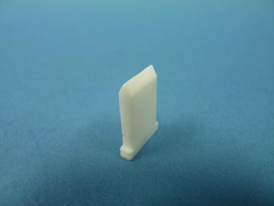
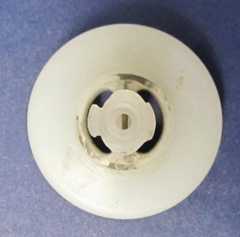
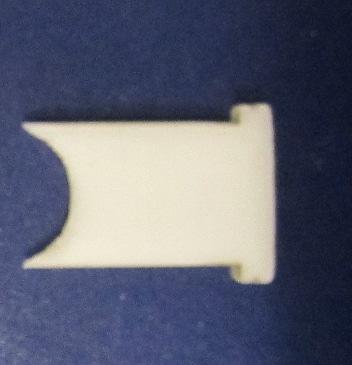
23 RPA-2 POWDER APPLICATOR - Maintenance 5. Remove rear plugs to view elbows only 6. View of Lower Powder Tube and Ring Ass y, and O-ring in Correct Orientation. 5a. Lift Elbow Off Lower Powder Tube and Ring Ass y 6a. Lift Lower Powder Tube and Ring Ass y 5b. Pull Out 6b. Lower Powder Tube and Ring Ass y Alignment Pin Alignment Pin (White) LN

 SLOT")

 6e.")
24 RPA-2 POWDER APPLICATOR - Maintenance 6c. Slot Position 7. Backside of Applicator W/Counter electrode contact (if equipped) SLOT Counter Electrode Contact 6d. Extract Out Top Port 8. Remove (4) Screws From Applicator Plate (6mm Hex Key) 6e. View of Lower Powder Tube and Ring Ass y and Slot 9. Remove Applicator Plate SLOT 2 LN


 c.")


25 RPA-2 POWDER APPLICATOR - Maintenance 0. Remove Cascade b. Resistor. Counter Electrode Dis-Assembly (If Equipped) c. Counter Electrode Parts in Order of Installation a. Contact Spring Assembly 2. Counter electrode (Front of Applicator) Moun ng Screw (2) LN
")


26 RPA-2 POWDER APPLICATOR - Maintenance 2a. Contact Spring Front (Shown With Mounting Screws Loose) Mounting Screw 3c. Parts Required For No Counter Screws Counter Electrode Blank Contact Spring, part of Gun Counter Electrode Contact Blank 3. No Counter Electrode Option Counter Electrode Contact Blank 3a. Counter Electrode Blank (Shown With Mounting Screws Loose) Screw Counter Electrode Blank Body Option Without Spring Contact 23 LN


 Wear Bar and")

27 RPA-2 POWDER APPLICATOR - Maintenance Nozzle Assembly (A295-00) Diffuser and Nozzle Holder (Tighten Until Stop) Wear Bar and Conductive Seal Wear Bar Slot (Push Wear Bar Straight In) Slot LN
28 RPA-2 POWDER APPLICATOR - Maintenance High Voltage Contact Repair Pull damaged spring and wire out from the front of applicator with pliers. Insert new contact assembly from front of application until spring rests in the bottom of the hole. From inside the cascade labyrinth, use a 3/6 diameter flat-end plastic rod and bend over flat. High Voltage Contact Repair 25 LN
 which must align with the alignment pin in the gun body for proper fit of components.")
29 RPA-2 POWDER APPLICATOR - Maintenance ASSEMBLY OF THE APPLI- CATOR Assemble the applicator in reverse order of the disassembly. Assembly Notes: Note: The lower powder tube has an alignment slot (see above) which must align with the alignment pin in the gun body for proper fit of components.. The lower powder tube and ring ass y elbow, and upper powder tube must align to create a seal. The best method is to assemble all three parts loosely, then tighten the thumb screws, and then tighten the shaping air or shroud. SLOT 2. The power hose connection should always be rotated in until the lower powder tube and ring ass y seals in the powder elbow. Alignment Pin (White color) LN


30 RPA-2 POWDER APPLICATOR - Maintenance Normal Deflector Normal Nozzle Holder Normal Wear Bar 27 Replace Deflector Replace Nozzle Replace Wear Bar LN
31 RPA-2 POWDER APPLICATOR - Parts DETAIL C SCALE : C OR D RPA-2 ASSEMBLY LN
32 RPA-2 POWDER APPLICATOR - Parts D 4 RPA-2 ASSEMBLY (CONT D.) 29 LN
33 RPA-2 POWDER APPLICATOR - Parts RPA-2 with Open Bore Nozzle RPA-2 with Replaceable Elbow, Upper Tube, and Electrode Holder RPA-2 ASSEMBLY (CONT D.) LN
34 RPA-2 POWDER APPLICATOR - Parts ITEM PART NUMBER A A A G A O N M L K E SSF-2052 A29-00 C A C A Z AA A A57-00 A74-00 A24-00 A73-00 A22-00 J I B H W A X Y V A B P R S T U A A30-00 A3-00 D A46-00 PARTS LIST DESCRIPTION INLET FITTING REAR PLATE ROBOT PLATE ASS'Y. CASCADE HP404 FITTING, 8 MM ODT X /4 BSP BODY, RETAINING CAP PLUG, RETAINING, CONTACT PIN SPRING, CLOSED AND GROUND PIN CONTACT PLUG CONTACT LOW VOLTAGE CABLE (QUICK DISCONNECT) SET SCREW 3/8 LG X 0-24 FITTING, /4 UNIVERSAL X METRIC ODT PNEUMATIC ROBOT ADAPTER (FANUC P-200/P-250) MOUNTING RING SCREW, STAINLESS /4-20 X 3/4 LG. S.H.C.S. AIR STUD, MEDIUM MACHINED O-RING, VITON O-RING, VITON O-RING, VITON COVER SCREW (M5 X 0.8) NYLON UPPER POWDER TUBE LOWER POWDER TUBE AND RING ASSEMBLY TOP PLUG O-RING (SOLVENT RESISTANT) REAR PLUG O-RING (SOLVENT RESISTANT) CHARGING RING, SECONDARY OR BLANK SPACER SCREW (M3 X 0.5 X 0 FLT HD.) #2 ELECTRODE HOLDER ASSEMBLY SHAPING AIR RING ASSEMBLY GROUND CABLE ASSEMBLY (RMA-303) SCREW, SOC HD CAP M8 X 25MM LG RESISTOR, HIGH MEGAOHM,.5 GIG CONTACT SPRING RPA GUN BODY ASSEMBLY ELBOW OPEN BORE FLAT JET NOZZLE ASSEMBLY HOLE PLUG, COUNTER ELECTRODE (NOT SHOWN) O-RING, SOLVENT PROOF POWDER TUBE THREAD ADAPTER POWDER TUBE FITTING POWDER TUBE CLAMP O-RING ( 2.0 X.50 VITON) TOOL (NOT SHOWN) LABEL O-RING (SOLVENT RESISTANT) LOW VOLTAGE CABLE EXTENSION PLUG QTY LN
35 RPA-2 POWDER APPLICATOR - Parts TABLE A Upper Tube and Elbow DASH No A A DESCRIPTION R S T U A96-00 A99-0 UPPER POWDER TUBE- ELBOW (DENSE PHASE) 2 A96-00 A99-0 UPPER POWDER TUBE- ELBOW (VENTURI PHASE) A33-00 A32-00 A27-00 A30-00 LN
36 RPA-2 POWDER APPLICATOR - Parts TABLE B Electrode Holder DASH B B DESCRIPTION A295- ELECTRODE HOLDER ASSEMBLY W/ REPLACEMENT WEAR BAR 2 A A38-00 OPEN BORE FLAT JET NOZZLE ASSEMBLY TABLE C ROBOT ADAPTER DASH NO. C DESCRIPTION NONE A FANUC ROBOT ADAPTER (P-200/P-250) 2 A MOTOMAN ROBOT ADAPTER (PX-2850) 3 A MOTOMAN ROBOT ADAPTER (PX-2900) 4 A ABB ROBOT ADAPTER (5400 ENHANCED) 33 LN
37 RPA-2 POWDER APPLICATOR - Parts TABLE D LOW VOLTAGE CABLE DASH NO. D E DESCRIPTION LENGT H 00 N/A 0 A224-5 A LOW VOLTAGE CABLE QUICK CONNECT TO MICROPAK( HARD WIRE VER- 5 FT. 02 A A LOW VOLTAGE CABLE QUICK CONNECT TO MICROPAK( HARD WIRE VER- 25 FT. 03 A A LOW VOLTAGE CABLE QUICK CONNECT TO MICROPAK( HARD WIRE VER- 40 FT. 04 A A LOW VOLTAGE CABLE QUICK CONNECT TO MICROPAK( HARD WIRE VER- 50 FT. 05 A A LOW VOLTAGE CABLE QUICK CONNECT TO MICROPAK( HARD WIRE VER- 75 FT. 06 A A LOW VOLTAGE CABLE QUICK CONNECT TO MICROPAK (QUICK CONNECT VERSION END TO STANDALONE MICROPAK) 25 FT. 07 A A LOW VOLTAGE CABLE QUICK CONNECT TO MICROPAK (QUICK CONNECT VERSION END TO STANDALONE MICROPAK) 50 FT. 08 A A LOW VOLTAGE CABLE QUICK CONNECT TO MICROPAK (QUICK CONNECT VERSION END TO STANDALONE MICROPAK) 75 FT. 09 A LOW VOLTAGE CABLE QUICK CONNECT TO MICROPAK (QUICK CONNECT VERSION END TO STANDALONE MICROPAK) 25 FT. 0 A LOW VOLTAGE CABLE QUICK CONNECT TO MICROPAK (QUICK CONNECT VERSION END TO STANDALONE MICROPAK) 50 FT. A LOW VOLTAGE CABLE QUICK CONNECT TO MICROPAK (QUICK CONNECT VERSION END TO STANDALONE MICROPAK) 75 FT. LN
38 RPA-2 POWDER APPLICATOR - Parts TABLE E STANDALONE POWER SUPPLY DASH NO. F DESCRIPTION G CASCADE 0 NO MICROPAK HP-505 CASCADE A A789-0 MICROPAK & DISCRETE WITH STANDALONE ENCL. HP A MICROPAK & 2 DISCRETE WITH STANDALONE ENCL. HP A MICROPAK & DISCRETE WITH STANDALONE ENCL. HP A MICROPAK & 2 DISCRETE WITH STANDALONE ENCL. HP-404 A A NO MICROPAK HP-404 CASCADE LN
39 RPA-2 POWDER APPLICATOR - Parts TABLE F SHAPING AIR RING / COUNTER ELECTRODE DASH NO. H DESCRIPTION I J K L M N O P V X Y NONE A5-00 SHAPING AIR RING (EXTERNAL) WITH COUNTER ELECTRODE A A A A A A SHROUD AIR (OPEN BORE NOZ- ZLE) WITH COUN- TER ELECTRODE A A A A A A5-00 SHAPING AIR RING (EXTERNAL) WITHOUT COUN- TER ELECTRODE A A A A A SHROUD AIR (OPEN BORE NOZ- ZLE) WITHOUT COUNTER ELEC- TRODE A A A A LN
 2 A680-25 CABLE, HIGH VOLTAGE GROUND (25 FT.")
 5 A680-00 CABLE, HIGH VOLTAGE GROUND (00 FT.")
 - Parts List Item # Part # Description QTY A42-00 THREADED RING (SHAPING AIR 2 A43-00 SHAPING AIR RING")
40 RPA-2 POWDER APPLICATOR - Parts TABLE G GROUND CABLE ASSEMBLY DASH NO. W DESCRIPTION A680-0 CABLE, HIGH VOLTAGE GROUND (0 FT.) 2 A CABLE, HIGH VOLTAGE GROUND (25 FT.) 3 A CABLE, HIGH VOLTAGE GROUND (50 FT.) 4 A CABLE, HIGH VOLTAGE GROUND (75 FT.) 5 A CABLE, HIGH VOLTAGE GROUND (00 FT.) RPA-2 Powder Applicator Shaping Air Cowl (A5-00) RPA-2 Powder Applicator Shaping Air Cowl (A5-00) - Parts List Item # Part # Description QTY A42-00 THREADED RING (SHAPING AIR 2 A43-00 SHAPING AIR RING ORIFICE (0,7 MM) 32 3 A34-00 SHAPING AIR RING 4 A63-00 O-Ring 5 A50-00 O-Ring 32 6 A49-00 O-Ring 2 7 A48-00 O-Ring 8 A47-00 O-Ring 37 LN
41 RPA-2 POWDER APPLICATOR - Parts Shroud air ( Open Bore Nozzle) (A ) SHROUD AIR (OPEN BORE NOZZLE) (A ) - PARTS LIST Item # Part # DESCRIPTION QTY A SHAPING AIR SHROUD 2 A SHAPING AIR RING 3 A49-00 O-RING 2 4 A M2 X 8 mm LONG FLAT HEAD SCREW O-RING 6 A63-00 O-RING LN
42 RPA-2 POWDER APPLICATOR - Parts Electrode Holder (A295-XX) Electrode Holder (A295-XX) - PARTS LIST Item # Description Part Number Qty. Deflector A E 2 C Ring A Conductive Seal A Hollow Electrode Holder Assembly A Electrode Holder B 6 #2 Sleeve A Wear Bar C D 39 LN
43 RPA-2 POWDER APPLICATOR - Parts ELECTRODE HOLDER MODEL IDENTIFICATION When ordering, use A295-A or B as indicated Tables A and B. Two digits must follow the Basic Part Number. For Example: A295- A B Basic Part Number Table B Electrode Holder with Bar With or Without Deflector TABLE A TABLE A # 2 ELECTRODE DEFLECTOR Dash No. Description A QTY Deflector A No Deflector TABLE B # 2 ELECTRODE HOLDER Dash No. Description B Holder C Wear Bar D QTY UHMW Electrode Holder (Replaceable Wear Bar) 2 UHMW Electrode Holder (Wear Bar Not Replaceable) A290-0 A A302-0 LN
44 RPA-2 POWDER APPLICATOR - Parts Recommended Spare Parts Part # Description Qty. Open Bore Nozzle Application A Open Bore Nozzle A38-00 Conductive Seal O-ring A63-00 O-ring A49-00 O-ring Electrode Holder /Shape Air Application option A295-XX Electrode Holder Assembly (See Page 42) A38-00 Conductive Seal A63-00 O-ring A50-00 O-ring A49-00 O-ring A48-00 O-ring A47-00 O-ring A Wear Bar A290-0 Electrode Holder (use with A Wear Bar) A302-0 Electrode Holder with non-replaceable Wear Bar Counter Electrode Application Resistor (5 gig ohm) A Screw (M3 x 0 Flt Hd. SS) 2 A Charging Ring, Secondary A Plug, Contact Spring No Counter Electrode Application A Charging Ring Blank A Screw ( M3 x 0 Flt Hd, Nylon) 2 Gun Body Assembly 3 A Gun Body Assy. / Counter Electrode Application A Gun Body Assy. / Non Counter Electrode Application 4 LN
45 RPA-2 POWDER APPLICATOR - Parts Recommended Spare Parts (CONT D.) Part # Description Qty Parts Common To All Applicators O-ring O-ring O-ring O-ring A3-00 O-ring A30-00 O-ring A24-00 O-ring (for Top Plug) A22-00 O-ring (for Rear Plug) A74-00 Top Plug A73-00 Rear Plug A Cover A Screw, Nylon (for A Cover) 4 A29-00 Fitting, 8mm Tube A Screw (M8 x 25 SHCS Fiberglass) (for Rear Plate) 4 A96-00 Upper Powder Tube (Dense Phase Application) A99-0 Top Elbow (Dense Phase or Venturi Application) A96-03 Upper Powder Tube (Venturi application) A57-00 Lower Powder Tube and Ring Ass y A680-XX Ground Cable Assembly (See page 4) A2239-XX Low Voltage Cable (See page 38) A224-XX Low Voltage Cable extension (See page 38) LN
46 RPA-2 POWDER APPLICATOR - Warranty Policies WARRANTY POLICIES LIMITED WARRANTY Ransburg will replace or repair without charge any part and/or equipment that falls within the specified time (see below) because of faulty workmanship or material, provided that the equipment has been used and maintained in accordance with Ransburg's written safety and operating instructions, and has been used under normal operating conditions. Normal wear items are excluded. THE USE OF OTHER THAN RANSBURG APPROVED PARTS, VOID ALL WARRAN- TIES. SPARE PARTS: One hundred and eighty (80) days from date of purchase, except for rebuilt parts (any part number ending in "R") for which the warranty period is ninety (90) days. EQUIPMENT: When purchased as a complete unit, (i.e., guns, power supplies, control units, etc.), is one () year from date of purchase. WRAPPING THE APPLICATOR, ASSO- CIATED VALVES AND TUBING, AND SUPPORTING HARDWARE IN PLASTIC, SHRINK-WRAP, OR ANY OTHER NON- APPROVED COVERING, WILL VOID THIS WARRANTY. RANSBURG'S ONLY OBLIGATION UNDER THIS WARRANTY IS TO RE- PLACE PARTS THAT HAVE FAILED BECAUSE OF FAULTY WORKMANSHIP OR MATER-IALS. THERE ARE NO IMPLIED WAR-RANTIES NOR WARRAN- TIES OF EITHER MERCHANTABILITY OR FITNESS FOR A PARTICULAR PURPOSE. RANS-BURG ASSUMES NO LIABILITY FOR INJURY, DAMAGE TO PROPERTY OR FOR CONSEQUENTIAL DAMAGES FOR LOSS OF GOODWILL OR PRODUC- TION OR INCOME, WHICH RESULT FROM USE OR MISUSE OF THE EQUIPMENT BY PURCHASER OR OTHERS. EXCLUSIONS: If, in Ransburg's opinion the warranty item in question, or other items damaged by this part was improperly installed, operated or maintained, Ransburg will assume no responsibility for repair or replacement of the item or items. The purchaser, therefore will assume all responsibility for any cost of repair or replacement and service related costs if applicable. 43 LN
47 RPA-2 POWDER APPLICATOR Changes made to LN Service Manual: Page 20, and 2, Lower Powder Tube and Ring Ass y was two (2) parts; Lower Tube and Ring. Page 28 and 29 Revised drawing to show Lower Powder Tube and Ring Ass y. Page 3 Item #29 was A7 Lower Tube and item #46 was A78 Ring. Page 42 A57-00 was A78-00 Manufacturing 90 North Wayne Street Angola, Indiana Telephone: Fax: Technical Service Assistance 320 Philips Ave. Toledo, Ohio Telephone (toll free): Fax: Technical Support Representative will direct you to the appropriate telephone number for ordering Spare Parts. 203 Ransburg. All rights reserved. Form No. LN Models and specifications subject to change without notice. Litho in U.S.A. 03/3 LN
RCS Positive Displacement Pump Series
 SERVICE MANUAL LN-9415-02 March 2017 RCS Positive Displacement Pump Series DLC Flushable Pump Series A13622-00 3.5 cc/rev A13623-00 6.0 cc/rev A13624-00 9.7 cc/rev DLC Non-Flushable Pump Series A13619-00
Inline/Piggable Dual Modular Color Changer
 PRODUCT MANUAL CS-11-02.1 Inline/Piggable Dual Modular Color Changer MODEL: A12846-XX IMPORTANT: Before using this equipment, carefully read SAFETY PRECAUTIONS, starting on page 1, and all instructions
Ransburg COLOR SELECT SYSTEM MODEL: CCV-6100
 SERVICE MANUAL (Replaces CS-95-01.1) March 2013 COLOR SELECT SYSTEM MODEL: CCV-6100 IMPORTANT: Before using this equipment, carefully read SAFETY PRECAUTIONS, starting on page 1, and all instructions in
PAINT, HIGH VOLTAGE & SCI TEST EQUIPMENT
 SERVICE MANUAL TE-98-01.7 (Replaces TE-98-01.6) JUNE - 2014 PAINT, HIGH VOLTAGE & SCI TEST EQUIPMENT MODEL: 76652-01 HIGH VOLTAGE PROBE 76652-02 SPRAYABILITY/SCI METER 76652-03 PAINT RESISTIVITY METER
Ransburg COLOR VALVE STACK MODEL: CCV-5100
 Ransburg SERVICE MANUAL LN-93-6.3 (Replaces LN-93-6.2) March - 23 COLOR VALVE STACK MODEL: CCV-5 IMPORTANT: Before using this equipment, carefully read SAFETY PRECAUTIONS, starting on page, and all instructions
COLOR VAL MODEL: CCV-5100 IMPORTANT
 COLOR VAL ALVE STACK SERVICE MANUAL LN-93-6. 3-6. (Replaces LN-93-6) October - 27 MODEL: CCV-5 IMPORTANT ANT: : Before using this equipment, care- fully read SAFETY PRECAUTIONS, starting on page, and all
EVOLVER SE ROBOTIC ATOMIZERS
 SERVICE MANUAL AA-09-01.3 MARCH - 2015 EVOLVER SE ROBOTIC ATOMIZERS MODEL: A12455-XXXXXXXX IMPORTANT: Before using this equipment, carefully read SAFETY PRECAUTIONS, starting on page 1, and all instructions
EVOLVER SE ROBOTIC ATOMIZERS
 SERVICE MANUAL AA-15-01 DECEMBER - 2016 EVOLVER SE ROBOTIC ATOMIZERS MODEL: A13901-XXXXXXXXX IMPORTANT: Before using this equipment, carefully read SAFETY PRECAUTIONS, starting on page 1, and all instructions
EVOLVER 303 DUAL PURGE SOLVENTBORNE ROBOTIC ATOMIZERS
 SERVICE MANUAL AA-08-01.5 (Replaces AA-08-01.4) MAY - 2015 TM EVOLVER 303 DUAL PURGE SOLVENTBORNE ROBOTIC ATOMIZERS With MODEL: A12374-XXX Technology IMPORTANT: Before using this equipment, carefully read
FOR IN-DIRECT CHARGE WATERBASED APPLICATORS. MODEL: RXi
 SERVICE MANUAL AH-15-02.1.1 FEBRUARY - 2016 By Ransburg APPLICATORS FOR IN-DIRECT CHARGE WATERBASED APPLICATORS MODEL: 80445 RXi IMPORTANT: Before using this equipment, carefully read SAFETY PRECAUTIONS,
EVOLVER 303 SOLVENTBORNE ROBOTIC ATOMIZERS
 SERVICE MANUAL AA-07-03.4 (Replaces AA-07-03.3) MAY - 2015 TM EVOLVER 303 SOLVENTBORNE ROBOTIC ATOMIZERS MODEL: A11976-XXX IMPORTANT: Before using this equipment, carefully read SAFETY PRECAUTIONS, starting
9060 CLASSIC HIGH VOLTAGE CONTROLLER (HV3 - Handguns)
") SERVICE MANUAL CP-13-06.4 9060 CLASSIC HIGH VOLTAGE CONTROLLER (HV3 - Handguns) MODEL: 80130-XXX IMPORTANT: Before using this equipment, carefully read SAFETY PRECAUTIONS, starting on page 1, and all instructions
SERVICE MANUAL CP-13-06.4 9060 CLASSIC HIGH VOLTAGE CONTROLLER (HV3 - Handguns) MODEL: 80130-XXX IMPORTANT: Before using this equipment, carefully read SAFETY PRECAUTIONS, starting on page 1, and all instructions
EasySelect-Cup Manual Powder Gun
 E Operating Instructions and Spare parts list EasySelect-Cup Manual Powder Gun EasySelect-Cup 27 28 EasySelect-Cup Table of Contents Safety rules EasySelect-Cup Manual Powder gun...........................................
FIBEROPTIC FLOWMETER HIGH AND LOW PRESSURE
 SERVICE MANUAL FM-14-03 FEBRUARY - 2015 FIBEROPTIC FLOWMETER HIGH AND LOW PRESSURE MODEL: A12713-00 IMPORTANT: Before using this equipment, carefully read SAFETY PRECAUTIONS, starting on page 1, and all
SERVICE MANUAL KK-5051 DISPOSABLE KB II CUP LINER
 SERVICE MANUAL KK-5051 DISPOSABLE KB II CUP LINER SB-4-207-G (11/2015) 1 / 8 IMPORTANT: Read and follow all instructions and SAFETY PRECAUTIONS on Pages 1 and 4 before using this equipment. Retain for
EVOLVER 500 SERIES DUAL PURGE SOLVENTBORNE ROBOTIC ATOMIZERS
 SERVICE MANUAL AA-14-02.1 JANUARY - 2017 EVOLVER 500 SERIES DUAL PURGE SOLVENTBORNE ROBOTIC ATOMIZERS MODEL: A13758-XXXXX IMPORTANT: Before using this equipment, carefully read SAFETY PRECAUTIONS, starting
Ransburg REA AUTOMATIC APPLICATORS. MODELS: and (Not FM Approved) 900A. 9000W (Not FM Approved) 9000R
 900A. 9000W (Not FM Approved) 9000R") Ransburg SERVICE MANUAL (Replaces AA-99-02.4) April - 2013 REA AUTOMATIC APPLICATORS 900A 9000R 9000W (Not FM Approved) MODELS: 77359 and 76110 77140 (Not FM Approved) IMPORTANT: Before using this equipment,
Ransburg SERVICE MANUAL (Replaces AA-99-02.4) April - 2013 REA AUTOMATIC APPLICATORS 900A 9000R 9000W (Not FM Approved) MODELS: 77359 and 76110 77140 (Not FM Approved) IMPORTANT: Before using this equipment,
FOR DIRECT CHARGE WATER BASED APPLICATORS
 SERVICE MANUAL AH-17-04-R0.0 By Ransburg APPLICATORS FOR DIRECT CHARGE WATER BASED APPLICATORS MODEL: 81520 RFXw IMPORTANT: Before using this equipment, carefully read SAFETY PRECAUTIONS, starting on page
EstaQuick AEMD-600 Automatic Applicator
 SERVICE MANUAL EN EstaQuick AEMD-600 Automatic Applicator 0518 II (2) G EEx 0.24 mj SIRA 11ATEX5240X Model: AEMD-600 IMPORTANT: Before using this equipment, carefully read SAFETY PRECAUTIONS, starting
T-AGPZ-F158/F159/F208/F209/S8/S9 COMPACT AUTO. GUN Operation Manual
 T-AGPZ-F158/F159/F208/F209/S8/S9 COMPACT AUTO. GUN Operation Manual Important:Read and follow all instructions and SAFETY PRES before using this equipment. DESCRIPTION T-AGPZ GUN is a low flow rate automatic
VECTOR R SERIES CASCADE APPLICATORS
 SERVICE MANUAL AH-06-01.16 TM VECTOR R SERIES CASCADE APPLICATORS MODELS: 79500 R90 Cascade - Solventborne 79501 R70 Cascade - Solventborne 79523 R90 Cascade - Waterborne For Use With 80131-xxx Control
RMA-580 ROBOT MOUNTED ROTARY ATOMIZER. For Waterborne and Solvent Borne Paint Direct Charge
 SERVICE MANUAL LN-9277-13.1 JUNE - 2014 Ransburg RMA-580 ROBOT MOUNTED ROTARY ATOMIZER For Waterborne and Solvent Borne Paint Direct Charge MODEL: A13367 IMPORTANT: Before using this equipment, carefully
RediCoat by Nordson. Hopper and VBF Dolly Systems. Customer Product Manual Part A Issued 10/07
 RediCoat by Nordson Hopper and VBF Dolly Systems Customer Product Manual Part 1082648A Issued 10/07 This document is subject to change without notice. Nordson Corporation Amherst, Ohio USA 2 Table of Contents
VECTOR R SERIES CLASSIC APPLICATORS
 SERVICE MANUAL AH-06-02.13 TM VECTOR R SERIES CLASSIC APPLICATORS MODELS: 79503 R90 Classic - Solventborne 79504 R70 Classic - Solventborne 79520 R90 Classic - Waterborne For Use With 80130-XXX 9060 Power
APOLLO-L Spray Gun Operation Manual
 APOLLO-L Spray Gun Operation Manual Important:Read and follow all instructions and SAFETY PRECAUTIONS before using this equipment. Retain for future reference. The gun body of this model is finished with
ARCHIVE MODEL: X / REA-IV APPLICATOR X / REA-III APPLICATOR X / REA-III AUTOMA X / M90 CLASSIC APPLICATOR IMPORTANT
 SERVICE MANUAL (Replaces CP-97-02.4) May - 2008 9040 CLASSIC HIGH VOLTAGE POWER SUPPLY (for the REA TM & M90 TM Classic Coating Systems) MODEL: 76447-0X / REA-IV APPLICATOR 76447-2X / REA-III APPLICATOR
for the No. 2 Process TM Handgun
 SERVICE MANUAL (Supercedes CP-97-03.5) 9040 CLASSIC HIGH VOLTAGE POWER SUPPLY for the No. 2 Process TM Handgun MODELS: 76657-4 NO.2 HANDGUN, ELECTRIC MOTOR, DOMESTIC VERSION 76657-42 NO.2 HANDGUN, ELECTRIC
SERVICE MANUAL LN June Ransburg AEROBELL 268 MODEL: A13657
 SERVICE MANUAL LN-9282-14 June - 2014 Ransburg TM AEROBELL 268 MODEL: A13657 IMPORTANT: IMPORTANT: Before Before using using this equipment, this equipment, carefully carefully read SAFETY read SAFETY
Airless Spray Gun INSTRUCTIONS DP psi (345 bar) Maximum Working Pressure
 Maximum Working Pressure") INSTRUCTIONS DP-6376 Airless Spray Gun 5000 psi (345 bar) Maximum Working Pressure INSTRUCTIONS This manual contains important warnings and information. READ AND KEEP FOR REFERENCE. Table of Contents Warnings......................................
INSTRUCTIONS DP-6376 Airless Spray Gun 5000 psi (345 bar) Maximum Working Pressure INSTRUCTIONS This manual contains important warnings and information. READ AND KEEP FOR REFERENCE. Table of Contents Warnings......................................
Vantage Manual Powder Spray Gun
 Vantage Manual Powder Spray Gun Customer Product Manual Issued 04/16 For parts and technical support, call the Finishing Customer Support Center at (800) 433-9319. This document is subject to change without
PRO Auto Xs Air Spray Gun
 Instructions/Parts List ELECTROSTATIC, FOR WATERBORNE COATINGS PRO Auto Xs Air Spray Gun 309457G EN Part No. 244591, Series A 100 psi (0.7 MPa, 7 bar) Maximum Air Inlet Pressure 100 psi (0.7 MPa, 7 bar)
OptiGun 2-AE Automatic Powder Gun (GA02)
") E Operating Instructions and Spare Parts List Automatic Powder Gun (GA02) 31 32 Table of Contents 1. Operating Instructions................................................... 1 1.1. Safety rules for electrostatic
E Operating Instructions and Spare Parts List Automatic Powder Gun (GA02) 31 32 Table of Contents 1. Operating Instructions................................................... 1 1.1. Safety rules for electrostatic
RMA-570 ROBOT MOUNTED ROTARY ATOMIZER INDIRECT CHARGE
 SERVICE MANUAL LN-9275-13.2 APRIL - 2015 RMA-570 ROBOT MOUNTED ROTARY ATOMIZER INDIRECT CHARGE MODEL: A13365 IMPORTANT: Before using this equipment, carefully read SAFETY PRECAUTIONS, starting on page
PRO ES Test Fixture, High Voltage Test Probe, & KV Meter
 INSTRUCTIONS PARTS LIST 308 217 This manual contains important warnings and information. READ AND RETAIN FOR REFERENCE Rev. B Supersedes A PRO ES Test Fixture, High Voltage Test Probe, & KV Meter To Test
Prodigy HDLV Pump. Customer Product Manual Part A02
 Prodigy HDLV Pump Customer Product Manual Issued 1/07 For parts and technical support, call the Industrial Coating Systems Customer Support Center at (800) 433-9319 or contact your local Nordson representative.
EasySelect GM01-E Manual Powder Gun
 E Operating Instructions and Spare parts list EasySelect GM01-E Manual Powder Gun EasySelect GM01-E 25 26 EasySelect GM01-E Table of Contents Safety rules Safety rules for electrostatic powder coating
GRAVITY FEED SPRAY GUN & CUP SPECIFICATIONS. Operating Instructions Warning Information Parts Breakdown. Fluid Orifice mm. Air Inlet:...
 Operating Instructions Warning Information Parts Breakdown SPECIFICATIONS Fluid Orifice... 1.4mm Air Inlet:...1/4 NPT Rec. Max. Inlet Pressure:...50 PSI CFM:... 3.1 at 50 PSI Nozzle Pressure... 10 PSI
Viscount I Hydraulic Motor and Displacement Pump
 INSTRUCTIONS-PARTS LIST 308 674 INSTRUCTIONS This manual contains important warnings and information. READ AND KEEP FOR REFERENCE. Rev. C Supersedes Rev. B Viscount I Hydraulic Motor and Displacement Pump
Ransburg VECTOR SOLO APPLICATORS. MODEL: Solventborne RS90-AS. SERVICE MANUAL AH May
 SERVICE MANUAL May - 2015 Ransburg TM VECTOR SOLO APPLICATORS MODEL: 79900 Solventborne RS90-AS IMPORTANT: Before using this equipment, carefully read SAFETY PRECAUTIONS, starting on page 1, and all instructions
USE and MAINTENANCE INSTRUCTION MANUAL AZ3 HTE2 AZ3 HTE2 HVLP GRAVITY. SPRAY GUN Series. en it fr es pt de se
 USE and MAINTENANCE INSTRUCTION MANUAL AZ3 HTE2 AZ3 HTE2 HVLP GRAVITY SPRAY GUN Series en it fr es pt de se TECHNICAL DATA Technical AZ3 HTE2 AZ3 HTE2 HVLP 1.0 80 180 1.3 10-15HTE 140 200 240 1.5 2.0 160
DISPLACEMENT PUMP INSTRUCTIONS-PARTS LIST Rev. K. Model , Series A Model , Series B Model , Series A
 INSTRUCTIONS-PARTS LIST INSTRUCTIONS This manual contains important warnings and information. READ AND KEEP FOR REFERENCE. DISPLACEMENT PUMP 308190 Rev. K 3000 psi (210 bar) MAXIMUM WORKING PRESSURE Model
Versa-Spray IPS Manual Electrostatic Porcelain Enamel Powder Spray Gun
 Versa-Spray IPS Manual Electrostatic Porcelain Enamel Powder Spray Gun Customer Product Manual Issued 11/06 For parts and technical support, call the Industrial Coating Systems Customer Support Center
SB ISS.04. Operation Manual AGMDPRO Automatic Spray Gun
 EN SB-2-991 ISS.04 Operation Manual AGMDPRO Automatic Spray Gun Table of Contents Topic Page Specification and Materials of Construction 3 EC Declaration of Conformity 3 Safety Precautions 4 Model Part
Versa-Spray II Automatic Powder Spray Gun
 Versa-Spray II Automatic Powder Spray Gun Customer Product Manual Issued 05/6 For parts and technical support, call the Industrial Coating Systems Customer Support Center at (800) 433-939 or contact your
MGFHVLP. Instructions/Parts. Mini Gravity Feed System E. Part No Includes MGFHVLP Mini Gravity Feed Spray Gun and MGC 125 Gravity Cup.
 Instructions/Parts MGFHVLP Mini Gravity Feed System FOR PRODUCT INFORMATION CALL: 1-800-742-7731 309989E For gravity feed spraying of automotive colors and clears. Ideal for touch-up and detail work. Important
B14 AAA FINE FINISH SERIES PUMP OUTFIT
 PRODUCT INFORMATION B14 AAA FINE FINISH SERIES PUMP OUTFIT The B14 AAA pump system is an air assisted airless unit which combines airless and conventional or HVLP air atomization technologies to produce
SERVICE MANUAL. (Replaces AA-99-02)
") SERVICE MANUAL (Replaces AA-99-02) REA AUTOMATIC GUNS 9000A 900A 9000R 9000W MODELS: 75795, 77359, 76110, 10, 77140 IMPORTANT: Before using this equipment, carefully read SAFETY PRECAUTIONS, starting on
SERVICE MANUAL (Replaces AA-99-02) REA AUTOMATIC GUNS 9000A 900A 9000R 9000W MODELS: 75795, 77359, 76110, 10, 77140 IMPORTANT: Before using this equipment, carefully read SAFETY PRECAUTIONS, starting on
PG 1-A Automatic Powder Gun
 E Operating Instructions and Spare Parts List Automatic Powder Gun 25 26 Tabel of Contents Safety rules for electrostatic powder coating operations Automatic powder gun...........................................
T1-Titanium Non-HVLP Spray Gun
 T1-Titanium Non-HVLP Spray Gun THE SPRAY GUN PEOPLE FOR PRODUCT INFORMATION CALL: 1-800-742-7731 Important Safety Instructions Read all warnings and instructions in this manual. Save these instructions.
Model , Series A 9 in. (23 cm) roller frame with 45 angle and 12 in. reach 1/2 in. (13 mm) nap roller cover
 roller frame with 45 angle and 12 in. reach 1/2 in. (13 mm) nap roller cover") Operating Instructions 309899 Rev. A This manual contains important warnings and information. READ AND KEEP FOR REFERENCE. INSTRUCTIONS Manufactured by Model 246818, Series A 9 in. (23 cm) roller frame
Operating Instructions 309899 Rev. A This manual contains important warnings and information. READ AND KEEP FOR REFERENCE. INSTRUCTIONS Manufactured by Model 246818, Series A 9 in. (23 cm) roller frame
B14 AAA FINE FINISH SERIES PUMP OUTFIT
 PRODUCT INFORMATION B14 AAA FINE FINISH SERIES PUMP OUTFIT The B14 AAA pump system is an air assisted airless unit which combines airless and conventional or HVLP air atomization technologies to produce
No. 2 Process Handgun Electric Motor Version
 SERVICE MANUAL EN No. Process Handgun Electric Motor Version MODEL: 97 IMPORTANT: Before using this equipment, carefully read SAFETY PRECAUTIONS, starting on page 5, and all instructions in this manual.
Econo-Coat Manual Powder Spray Gun
 Econo-Coat Manual Powder Spray Gun Customer Product Manual Issued 0/03 For parts and technical support, call the Industrial Coating Systems Customer Support Center at (800) 433-939 or contact your local
Prodigy HDLV Pump Manifold and Circuit Board
 Prodigy HDLV Pump Manifold and Circuit Board Customer Product Manual Issued 05/08 For parts and technical support, call the Finishing Customer Support Center at (800) 433-939. This document is available
SB-E ISS.05. Operation Manual AA4400A Automatic Air Assisted Airless Spray Gun
 EN SB-E-2-740 ISS.05 Operation Manual AA4400A Automatic Air Assisted Airless Spray Gun Contents Page 1 - Specification & Materials of construction... 3 2 - SAFETY WARNINGS... 4 3 - Model part numbers...
Instructions/Parts List. WB100 Isolation System and PRO Xs3 Spray Gun K ELECTROSTATIC, WATERBORNE, AIR SPRAY
 Instructions/Parts List ELECTROSTATIC, WATERBORNE, AIR SPRAY WB00 Isolation System and PRO Xs3 Spray Gun 309293K Important Safety Instructions Read all warnings and instructions in this manual. Save these
MODEL: 76480, 76482, 76485, 76488
 SERVICE MANUAL (Replaces AA-99-01) June - 2007 EFM TM AND EFMD TM SOLVENTBORNE ROBOTIC ATOMIZERS MODEL: 76480, 76482, 76485, 76488 IMPORTANT ANT: : Before using this equipment, carefully read SAFETY PRECAUTIONS,
Prodigy HDLV Generation II Pump Panel
 Prodigy HDLV Generation II Pump Panel Customer Product Manual Issued 01/10 For parts and technical support, call the Finishing Customer Support Center at (800) 433-9319. This document is subject to change
H2O-C14 AAA FINE FINISH SERIES PUMP OUTFIT
 PRODUCT INFORMATION H2O-C14 AAA FINE FINISH SERIES PUMP OUTFIT The H2O-C14 AAA pump system is an air assisted airless unit which combines airless and conventional or HVLP air atomization technologies to
D Instructions/Parts. Siphon Feed Detail Spray Gun D
 Instructions/Parts D-5-55 Siphon Feed Detail Spray Gun FOR PRODUCT INFORMATION CALL: 1-800-742-7731 309991D Important Safety Instructions Read all warnings and instructions in this manual. Save these instructions.
USE and MAINTENANCE INSTRUCTION MANUAL W-300 W-300 WB LPH-300 GRAVITY. SPRAY GUN Series. en it fr es pt de se
 USE and MAINTENANCE INSTRUCTION MANUAL W-300 W-300 WB LPH-300 GRAVITY SPRAY GUN Series en it fr es pt de se TECHNICAL DATA High T.E.C. series Nozzle_Needle set Combination W-300 WB W-300 W-300-081G 0.8
INSTRUCTIONS. US Patent Pending HVLP Turbine Guns
 INSTRUCTIONS 309317 INSTRUCTIONS This manual contains important warnings and information. READ AND KEEP FOR REFERENCE. Rev. A US Patent Pending HVLP Turbine Guns 10 psi (0.07 MPa,.7 bar) Maximum Inlet
OptiGun 2-AE1 Enamel automatic gun (GA02-E1 type)
") En Operating instructions and spare parts list OptiGun 2-AE1 Enamel automatic gun (GA02-E1 type) II 2 D Translation of the original operating instructions Documentation OptiGun 2-AE1 Enamel automatic gun
En Operating instructions and spare parts list OptiGun 2-AE1 Enamel automatic gun (GA02-E1 type) II 2 D Translation of the original operating instructions Documentation OptiGun 2-AE1 Enamel automatic gun
Tribomatic II Extended Automatic Powder Spray Gun
 Tribomatic II Extended Automatic Powder Spray Gun Customer Product Manual Issued 7/06 For parts and technical support, call the Industrial Coating Systems Customer Support Center at (800) 433-939 or contact
Operation Manual Cobra 1 Automatic Spray Gun
 SB-E-2-CBA1 ISS.06 Operation Manual Cobra 1 Automatic Spray Gun E P 1 12 1 Operation Manual Cobra 1 Automatic Spraygun Important Read and follow all instructions and Safety Precautions before using this
ATTENTION! READ BEFORE ATTACHING THE AIR HOSE
 Binks SV50 HVLP GRAVITY FEED SPRAY GUN & TOUCHUP GUN ATTENTION READ BEFORE ATTACHING THE AIR HOSE HVLP AIR SUPPLY REQUIREMENTS FULL SIZE GUN: 30 PSI inlet pressure provides 10 PSI at the air cap. Consumes
Operating Instructions and Spare Parts List. PG 1-Cup Gun. Issued 09/98
 E Operating Instructions and Spare Parts List 27 28 Table of Contents Directions for use Electrostatic Manual Spraying equipment for Powder Coating Safety rules for the electrostatic powder coating Technical
LN TURBODISK ASSEMBLY MODELS: IMPORTANT:
 SERVICE MANUAL TURBODISK ASSEMBLY MODELS: 78715 IMPORTANT: Before using this equipment, carefully read SAFETY PRECAUTIONS, starting on page 1, and all instructions in this manual. Keep this Service Manual
Versa-Spray IPS Automatic Electrostatic Porcelain Enamel Powder Spray Gun
 Versa-Spray IPS Automatic Electrostatic Porcelain Enamel Powder Spray Gun Customer Product Manual Issued 05/6 For parts and technical support, call the Industrial Coating Systems Customer Support Center
Zip-Tex Spray Gun. Instructions A. Model psi (0.86 MPa, 8.6bar) Maximum Working Pressure
 Maximum Working Pressure") Instructions Zip-Tex Spray Gun 311159A - For water-based materials only - (Consult your material supplier for Warnings and Application Requirements) Model 249458 125 psi (0.86 MPa, 8.6bar) Maximum Working
Instructions Zip-Tex Spray Gun 311159A - For water-based materials only - (Consult your material supplier for Warnings and Application Requirements) Model 249458 125 psi (0.86 MPa, 8.6bar) Maximum Working
Versa-Spray II Automatic Powder Spray Gun
 Versa-Spray II Automatic Powder Spray Gun Customer Product Manual Issued /06 For parts and technical support, call the Industrial Coating Systems Customer Support Center at (800) 433-939 or contact your
OptiSpray F Manual coating equipment
 En Operating instructions and spare parts list OptiSpray F Manual coating equipment Translation of the original operating instructions Documentation OptiSpray F Manual coating equipment Copyright 2006
Spray Nozzle Adapters
 INSTRUCTIONS-PARTS LIST 306 788 INSTRUCTIONS This manual contains important warnings and information. READ AND KEEP FOR REFERENCE. First choice when quality counts. Rev. G Supersedes Rev. F DIRECTIONAL
Tribomatic II Purgeable Automatic Powder Spray Gun
 Tribomatic II Purgeable Automatic Powder Spray Gun Customer Product Manual Issued 4/0 For parts and technical support, call the Industrial Coating Systems Customer Support Center at (800) 4-99 or contact
INSTRUCTIONS PARTS LIST This manual contains important warnings and information. READ AND RETAIN FOR REFERENCE
 INSTRUCTIONS PARTS LIST 308 493 This manual contains important warnings and information. READ AND RETAIN FOR REFERENCE Rev. A Second Gun Hose Kit 100 psi (6.9 bar) Maximum Working Pressure These kits include
M-3025CB-AV Fuel Pump
 SAVE THESE INSTRUCTIONS M-3025CB-AV Fuel Pump Owner s Manual TABLE OF CONTENTS General Information... 2 Safety Instructions... 2 Installation... 3 Operation... 4 Maintenance... 4 Repair... 5 Troubleshooting...
Polypropylene Piston Drum Pumps
 Please read and save this Repair Parts Manual. Read this manual and the General Operating Instructions carefully before attempting to assemble, install, operate or maintain the product described. Protect
PENTECH, INC. BD Spray Gun. Operating Manual Parts Manual May, 2008 Issue 1. Plural Component, Impingement Mixing, Mechanical Purge Spray Gun
 PENTECH, INC. Operating Manual Parts Manual May, 2008 Issue 1 Plural Component, Impingement Mixing, Mechanical Purge Spray Gun BD Spray Gun PENTECH, INC. 7256 21 st Street East Sarasota, FL 34243 Phone:
Page 1 of 12. Part# /30/2016
 Part# 1007480-02 9/30/2016 This manual contains important information concerning the installation and operation of the gun washers listed above. Read manual thoroughly and keep for future reference. INSTRUCTIONS
Ransburg VOLTAGE MASTER HIGH VOLTAGE POWER SUPPLY SYSTEM CONTROL PANEL MODEL: POWER SUPPLY MODEL: LEPS5001
 SERVICE MANUAL (Replaces CP-02-02.5) March - 2013 VOLTAGE MASTER HIGH VOLTAGE POWER SUPPLY SYSTEM CONTROL PANEL MODEL: 78789 POWER SUPPLY MODEL: LEPS5001 IMPORTANT: Before using this equipment, carefully
Model PRO 3500sc Electrostatic Air Spray Gun 65 kv, MANUAL GUN
 INSTRUCTIONS-PARTS LIST This manual contains important warnings and information. READ AND KEEP FOR REFERENCE. 307912 Rev. AC INSTRUCTIONS Model PRO 3500sc Electrostatic Air Spray Gun 65 kv, MANUAL GUN
Pressure Roller with 24-inch Fixed Extension - For application of architectural paints and coatings -
 Instructions Important Safety Instructions Read all warnings and instructions in this manual. Save these instructions. 311082D Pressure Roller with 24-inch Fixed Extension - For application of architectural
Powder Bell. Customer Product Manual Part A NORDSON CORPORATION AMHERST, OHIO USA
 Powder Bell Customer Product Manual Part NORDSON CORPORATION AMHERST, OHIO USA Nordson Corporation welcomes requests for information, comments and inquiries about its products. Address all correspondence
RS Gun Front Adapter Kits
 Kit Instructions RS Gun Front Adapter Kits 332520A EN For adapting the internal mix gun for specific field applications. For professional use only. Important Safety Instructions Read all warnings and instructions
SB-E-2-CBA1 ISS.13. Operation Manual Cobra 1 Automatic Spray Gun
 EN SB-E-2-CBA1 ISS.13 Operation Manual Cobra 1 Automatic Spray Gun Operation Manual Cobra 1 Automatic Spraygun Important Read and follow all instructions and Safety Precautions before using this equipment
Ransburg RMA-202 TEST STAND MODEL: FOR RMA-202
 10 0 10 0 100 100 100 100 100 ATOM AIR BEARING AIR SHAPING AIR SEAL AIR SERVICE MANUAL RMA-202 TEST STAND MODEL: 77918-08 FOR RMA-202 IMPORTANT: Before using this equipment, carefully read SAFETY PRECAUTIONS,
Model PRO 3500hc Electrostatic Air Spray Gun 65 kv, HIGH CONDUCTIVITY, MANUAL GUN
 INSTRUCTIONS-PARTS LIST This manual contains important warnings and information. READ AND KEEP FOR REFERENCE. 308018 Rev. W INSTRUCTIONS Model PRO 3500hc Electrostatic Air Spray Gun 65 kv, HIGH CONDUCTIVITY,
1.2 MM PRODUCTION SPRAY GUN
 1.2 MM PRODUCTION SPRAY GUN Stock Number M701 OWNERS MANUAL Please read these instructions carefully and retain them for future use. On occasion, after printing of our literature is completed, our manufacturers
Cutlass Fasteners, Inc. 83 Vermont Ave., Unit 6, Warwick, RI Tel: (401) Fax: (401) cutlass-studwelding.com
 Fax: (401) cutlass-studwelding.com") MODEL : PHM-10 SHORT CYCLE WELD GUN PART NO. : PHM-10 SERIAL NO. : PLEASE READ THIS OPERATION AND MAINTENANCE MANUAL CAREFULLY BEFORE USING YOUR NEW CUTLASS STUD WELDER. COPYRIGHT CFI 2009 email: sales@
MODEL : PHM-10 SHORT CYCLE WELD GUN PART NO. : PHM-10 SERIAL NO. : PLEASE READ THIS OPERATION AND MAINTENANCE MANUAL CAREFULLY BEFORE USING YOUR NEW CUTLASS STUD WELDER. COPYRIGHT CFI 2009 email: sales@
LS100L Battery-powered Punch Driver
 OPERATION MANUAL Serial Number GATOR LS100L Battery-powered Driver Read and understand all of the instructions and safety information in this manual before operating or servicing this tool. Register this
Voltmaster Centrifugal Trash Pumps
 Voltmaster Centrifugal Trash Pumps Model TSP2, TSP3 and TSP4 Owner s Manual February 2011 Table of Contents 1 Introduction............................ 1 1.1 Read before using..................... 1 1.2
KB II TWO-QUART PRESSURE CUPS KB-555 ALUMINUM, KB-545-SS STAINLESS STEEL
 SERVICE MANUAL KB II TWO-QUART PRESSURE CUPS KB-555 ALUMINUM, KB-545-SS STAINLESS STEEL GOVERNMENT NSN NO. 4940-01-106-1415 = KB-555 CUP EN IMPORTANT: Read and follow all instructions and SAFETY PRECAUTIONS
KB II TWO-QUART PRESSURE CUPS KB-555 ALUMINUM, KB-545-SS STAINLESS STEEL
 SERVICE MANUAL EN KB II TWO-QUART PRESSURE CUPS KB-555 ALUMINUM, KB-545-SS STAINLESS STEEL GOVERNMENT NSN NO. 4940-01-106-1415 = KB-555 CUP IMPORTANT! DO NOT DESTROY It is the Customer's responsibility
OWNER/OPERATOR MANUAL. Airmotor effective dia. in. 2.5
 MODELS 282050, 282716 & 283513 AIR OPERATED CHASSIS PUMP SERIES A OWNER/OPERATOR MANUAL SPECIFICATIONS Airmotor effective dia. in. 2.5 Airinlet Material outlet 1/4 NPTF 1/4 NPTF Liquid to Air Pressure
G8 Portable Fuel Transfer Pump Owner s Manual
 G8 Portable Fuel Transfer Pump Owner s Manual GENERAL INFORMATION This pump is designed for use only with gasoline (up to 15% alcohol blends such as E15), diesel fuel (up to 20% biodiesel blends such as
Application cup for OptiFlex 2 GM03 manual powder gun
 En Operating instructions and spare parts list Application cup for OptiFlex 2 GM03 manual powder gun Translation of the original operating instructions Documentation OptiFlex GM03 application cup Copyright
SPECIFICATIONS Horsepower: 1.5 HP Running Maximum PSI: 125 PSI Tank Capacity: 15 Gallons CFM: 6 40 PSI 5 90 PSI
 15 GALLON AIR COMPRESSOR Model: 7678 DO NOT RETURN TO STORE Please call 800-348-5004 for parts and service CALIFORNIA PROPOSITION 65 WARNING: You can create dust when you cut, sand, drill or grind materials
Model No. SP Low Volume Low Pressure (LVLP) Gravity Feed Spray Gun
 Gravity Feed Spray Gun") Model No. SP-33000 Low Volume Low Pressure (LVLP) Gravity Feed Spray Gun - 1 - TABLE OF CONTENTS: 1. Description 2. Specification and Technical Data 3. Important Safety Instruction 4. Instructions for
Model No. SP-33000 Low Volume Low Pressure (LVLP) Gravity Feed Spray Gun - 1 - TABLE OF CONTENTS: 1. Description 2. Specification and Technical Data 3. Important Safety Instruction 4. Instructions for
Vantage Modular Gun Control System
 Vantage Modular Gun Control System Customer Product Manual Issued 04/5 For parts and technical support, call the Finishing Customer Support Center at (800) 433-939. This document is available on the Internet
INSTRUCTIONS-PARTS LIST
 INSTRUCTIONS-PARTS LIST 308442 INSTRUCTIONS This manual contains important warnings and information. READ AND KEEP FOR REFERENCE. Rev. G AUTOMATIC ELECTROSTATIC, HIGH CONDUCTIVITY Model PRO 5500hcAir Spray