THERMAL ENGINEERING LAB MANUAL
|
|
|
- Melina Wheeler
- 6 years ago
- Views:
Transcription
1 THERMAL ENGINEERING LAB MANUAL
2 LIST OF EXPERIMENTS 1. I.C ENGINES PERFORMANCE TEST (4-STROKE DIESEL ENGINE 2. I.C ENGINES HEAT BALANCE 3. ECONAMICAL SPPED TEST (4-STROKE DIESEL ENGINE) 4. PERFORMANCE TEST ON RECIPROCATING AIR COMPRESSOR 5. PORT TIMING DIAGRAM OF A 2-STROKE PETROL ENGINE 6. VALVE TIMING DIAGRAM OF A 4-STROKE DIESEL ENGINE 7.. DIS-ASSEMBLY AND ASSEMBLY OF A ENGINE.
3 I.C ENGINES PERFORMANCE TEST (4-STROKE DIESEL ENGINE) AIM: To conduct performance test on 4-Stroke diesel engine (Single cylinder) and to draw the following graphs. 1. B.P Vs S.F.C 2. Mechanical efficiency Vs B.P 3. B.P Vs Indicated thermal efficiency 4. B.P Vs Indicated thermal efficiency 5. Air fuel Ratio Vs B.P 6. Air fuel Ratio Vs S.F.C THEORY: The Test Ring consists of Four-Stroke Diesel Engine, to be tested for performance, is connected to Rope Brake Drum with Spring Balace (Mechanical Dynamometer) with Exhaust Gas Calorimeter. The arrangement is made for the following measurements of the Set-up : 1) The Rate of Fuel Consumption is measured by using the pipette reading againt the known time. 2) Air Flow is measured by Manometer connected to Air Box. 3) The different mechanical loading is achieved by operating the spring balance of dynamometer in steps. 4) The different mechanical energy is measured by spring balance and radius of brake drum. 5) The Engine Speed (RPM) is measured by electronic digital RPM Counter. 6) Temperature at different points is measured by electronic digital Temperature Indicator. 7) Water Flow Rate through the engine & calorimeter is measured by Watermeter. The whole instrumentation is mounted on a self contained unit ready for table operation. PROCEDURE:
4 1. Check the diesel in the diesel tank. 2. Allow diesel, start the engine by using hand cranking. 3. The engine is set to the speed of 1500 RPM. 4. Apply load from the spring balance of dynamometer. 5. Allow some time so that the speed stabilizes. 6. Now take down spring balance readings. 7. Put tank valve in to pipette position and note down the time taken for particular quantity of fuel consumed by the engine. 8. Note down the temperature readings at different points. 9. Note down the water readings. 10. Repeat the procedure (4)&(7) for different loads. 11. Tabulate the readings as shown in the enclosed list. 12. After the experiment is over,keep the diesel control valve at mains position. Engine Speed in RPM OBSERVATIONS: Spring balance Readings F 1 In Kgs F 2 In Kgs Fuel pipette readings In Ml Time in Secs. Caloriemeter Water Temperature Inlet T 2 C Outlet T 3 C Engine head water temperature Inlet T 1 C Outlet T 2 C Exhaust gas temperature Inlet T 4 C Outlet T 5 C Air inlet T 6 C Air flow Manometer readings in mm of water 1 2(a) 2(b) 3(a) 3(b) 4(a) 4(b) 5(a) 5(b) 6(a) 6(b) Water flow rate in lpm
5 CALCULATIONS 1.FUEL CONSUMPTION IN Kg/Hr W F = Column(3a) oftablereadings Column(3b) oftablereadings x ENGINE OUT PUT BHP : BP= 2 2 N( F F ) r KW Where, N- Speed of engine in RPM r Radius of brake drum in mts =0.185 mt F 1 &F 2 - Force indicated on spring balance in KGs 3.SPECIFIC FUEL CONSUMPTION (SFC): SFC = WF BHP Kg/BHP. Hr 4. FUEL HP(THERMAL HORSE POWER), FHP= WF x CV x J 60 X 4500 Where, Cv = Calorific value of diesel= K.Cal /Kg J= Mechanical equivalent of heat=427 kg.m / K.Cal 5. PERCENTAGE THERMAL EFFICIENCY. % η th = BHP x 100 FHP 6. AIR CONSUMPTION IN Kg/ Hr Wa Wa = 0.6 x A 0 x Va x 1.29 x 60 x 60 Where, Ao = Area of the orifice in m 2 = 4 d2
6 Where d= Dia.of the orifice in m = mt Va = 2g (hm/ 1000) x [( w a) -1] Where g = 9.81 m/ sce 2 h m = Manometer reading in mm (column 5) ρ w = Density of water = 1000 Kg/ m 3 ρ a = Density of air = 1.29 Kg/ m 3 7.AIR TO FUEL CONSUMPTION RATIO. Air to fuel consumption ratio = W W a F Sl.NO 1 Engine RPM N Fuel Consumed W f In Kg/Hr Air Consumed W a In Kg/Hr Air to Fuel Ratio Wa / Wf Engine output BHP Specific fuel consumption SFC Fuel HP FHP Brake % η thermal efficiency RESULT; Performance test on 4-Stroke diesel engine(single cylinder) is conducted and the following graphs are plotted. 1. B.P Vs S.F.C 2. Mechanical efficiency Vs B.P 3. B.P Vs Indicated thermal efficiency 4. B.P Vs Indicated thermal efficiency 5. Air fuel Ratio Vs B.P 6. Air fuel Ratio Vs S.F.C
7 I.C ENGINES HEAT BALANCE AIM: To conduct performance test on 4-Stroke diesel engine(single cylinder) and to check the heat balance of I.C engine. THEORY: The Test Ring consists of Four-Stroke Diesel Engine, to be tested for performance, is connected to Rope Brake Drum with Spring Balance (Mechanical Dynamometer) with Exhaust Gas Calorimeter. The arrangement is made for the following measurements of the Set-up : 1) The Rate of Fuel Consumption is measured by using the pipette reading against the known time. 2) Air Flow is measured by Manometer connected to Air Box. 3) The different mechanical loading is achieved by operating the spring balance of dynamometer in steps. 4) The different mechanical energy is measured by spring balance and radius of brake drum. 5) The Engine Speed (RPM) is measured by electronic digital RPM Counter. 6) Temperature at different points is measured by electronic digital Temperature Indicator. 7) Water Flow Rate through the engine & calorimeter is measured by Wattmeter. The whole instrumentation is mounted on a self contained unit ready for table operation.
8 PROCEDURE: 1. Check the diesel in the diesel tank. 2. Allow diesel, start the engine by using hand cranking. 3. The engine is set to the speed of 1500 RPM. 4. Apply load from the spring balance of dynamometer. 5. Allow some time so that the speed stabilizes. 6. Now take down spring balance readings. 7. Put tank valve in to pipette position and note down the time taken for particular quantity of fuel consumed by the engine. 8. Note down the temperature readings at different points. 9. Note down the water readings. 10. Repeat the procedure (4)&(7) for different loads. 11. Tabulate the readings as shown in the enclosed list. 12. After the experiment is over,keep the diesel control valve at mains position. Engine Speed in RPM OBSERVATIONS: Spring balance Readings F 1 In Kgs F 2 In Kgs Fuel pipette readings In Ml Time in Secs. Caloriemeter Water Temperature Inlet T 2 C Outlet T 3 C Engine head water temperature Inlet T 1 C Outlet T 2 C Exhaust gas temperature Inlet T 4 C Outlet T 5 C Air inlet T 6 C Air flow Manometer readings in mm of water 1 2(a) 2(b) 3(a) 3(b) 4(a) 4(b) 5(a) 5(b) 6(a) 6(b) Water flow rate in lpm
9 CALCULATIONS: 1.FUEL CONSUMPTION IN Kg/Hr W F = Column(3a) oftablereadings Column(3b) oftablereadings x ENGINE OUT PUT BHP : BP= 2 2 N( F F ) r KW Where, N- Speed of engine in RPM r Radius of brake drum in mts =0.185 mt F 1 &F 2 - Force indicated on spring balance in KGs 3.SPECIFIC FUEL CONSUMPTION (SFC): SFC = WF BHP Kg/BHP. Hr 4. FUEL HP(THERMAL HORSE POWER), FHP= WF x CV x J 60 X 4500 Where, Cv = Calorific value of diesel= K.Cal /Kg J= Mechanical equivalent of heat=427 kg.m / K.Cal 5. PERCENTAGE THERMAL EFFICIENCY. % η th = BHP x 100 FHP 6. AIR CONSUMPTION IN Kg/ Hr Wa Wa = 0.6 x A 0 x Va x 1.29 x 60 x 60
10 Where, Ao = Area of the orifice in m 2 = 4 d2 Where d= Dia.of the orifice in m = mt Va = 2g (hm/ 1000) x [( w a) -1] Where g = 9.81 m/ sce 2 h m = Manometer reading in mm (column 5) ρ w = Density of water = 1000 Kg/ m 3 ρ a = Density of air = 1.29 Kg/ m 3 7.AIR TO FUEL CONSUMPTION RATIO. Air to fuel consumption ratio = W W a F 8.. TABLE OF CALCULATIONS. Sl.NO 1 Engine RPM N Fuel Consumed W f In Kg/Hr Air Consumed W a In Kg/Hr Air to Fuel Ratio Wa / Wf Engine output BHP Specific fuel consumption SFC Fuel HP FHP Brake % η thermal efficiency
11 9. HEAT BALANCE SHHET ON MINUTE BASIS: 1. Heat supplied in fuel = Fuel consumed in Kg/min x Cv W Fx = K.Cal / min i Heat carried away by engine head cooling water = m w x Cw x (T 1 -T 2 ) K.Cal / min ii 3. Heat carried away by calorie meter water = m w x Cw x (T 3 -T 2 ) K.Cal / min iii 4. Heat carried away by the exhaust gasses =m g x Cp x [T 5 -T 4 ] K.Cal / min iv m g = Mass of gas = W a + W F 5.Radiation & un Accounted = I-[ BHP+ II + III+IV] K.Cal/min V RESULT: Heat balance sheet is as follows CREDIT Kilo Calories % DEBIT 1.Brake power Kilo Calories BHP % BHP x 100 I 2.Engine head water II II x 100 I Heat supplied in fuel Calorie meter water III III x 100 I 4.Exhaust gasses IV IV x 100 I 5.Radiation and unaccounted ( by difference) V V x 100 I
12 ECONAMICAL SPPED TEST (4-STROKE DIESEL ENGINE) AIM: To conduct economical speed test on 4-Stroke diesel engine(single cylinder) THEORY: The Test Ring consists of Four-Stroke Diesel Engine, to be tested for performance, is connected to Rope Brake Drum with Spring Balance (Mechanical Dynamometer) with Exhaust Gas Calorimeter. The arrangement is made for the following measurements of the Set-up : 1) The Rate of Fuel Consumption is measured by using the pipette reading against the known time. 2) Air Flow is measured by Manometer connected to Air Box. 3) The different mechanical loading is achieved by operating the spring balance of dynamometer in steps. 4) The different mechanical energy is measured by spring balance and radius of brake drum. 5) The Engine Speed (RPM) is measured by electronic digital RPM Counter. 6) Temperature at different points is measured by electronic digital Temperature Indicator. 7) Water Flow Rate through the engine & calorimeter is measured by Water meter. The whole instrumentation is mounted on a self contained unit ready for table operation.
13 PROCEDURE: 1. Check the diesel in the diesel tank. 2. Allow diesel, start the engine by using hand cranking. 3. The engine is set to the speed of 1500 RPM. 4. Apply load from the spring balance of dynamometer. 5. Allow some time so that the speed stabilizes. 6. Now take down spring balance readings. 7. Put tank valve in to pipette position and note down the time taken for particular quantity of fuel consumed by the engine. 8. Note down the temperature readings at different points. 9. Note down the water readings. 10. Repeat the procedure (4)&(7) for different loads. 11. Tabulate the readings as shown in the enclosed list. 12. After the experiment is over,keep the diesel control valve at mains position. OBSERVATIONS: Engine Speed in RPM Spring balance Readings F 1 In Kgs F 2 In Kgs Fuel pipette readings Air flow Manometer readings in mm of water In ml Time in Secs. H1 H2
14 CALCULATIONS 1.FUEL CONSUMPTION IN Kg/Hr W F = Column(3a) oftablereadings Column(3b) oftablereadings x ENGINE OUT PUT BHP : BP= 2 2 N( F1 F ) r 4500 KW Where, N- Speed of engine in RPM r Radius of brake drum in mts =0.185 mt F 1 &F 2 - Force indicated on spring balance in KGs 3.SPECIFIC FUEL CONSUMPTION (SFC): SFC = WF BHP Kg/BHP. hr 4. FUEL HP(THERMAL HORSE POWER), FHP= WF x CV x J 60 X 4500 Where, Cv = Calorific value of diesel= K.Cal /Kg J= Mechanical equivalent of heat=427 kg.m / K.Cal 5. PERCENTAGE THERMAL EFFICIENCY. % η th = BHP x 100 FHP
15 6. AIR CONSUMPTION IN Kg/ Hr Wa Wa = 0.6 x A 0 x Va x 1.29 x 60 x 60 Where, Ao = Area of the orifice in m 2 = 4 d2 Where d= Dia.of the orifice in m = mt Va = 2g (hm/ 1000) x [( w a) -1] Where g = 9.81 m/ sce 2 h m = Manometer reading in mm (column 5) ρ w = Density of water = 1000 Kg/ m 3 ρ a = Density of air = 1.29 Kg/ m 3 7. AIR TO FUEL CONSUMPTION RATIO. Air to fuel consumption ratio = W W a F Sl.NO 1 Engine RPM N Fuel Consumed W f In Kg/Hr Air Consumed W a In Kg/Hr Air to Fuel Ratio Wa / Wf Engine output BHP Specific fuel consumption SFC Fuel HP FHP Brake % η thermal efficiency RESULT; Economical speed test on 4-Stroke diesel engine(single cylinder) is conducted. From the graph economical speed of engine
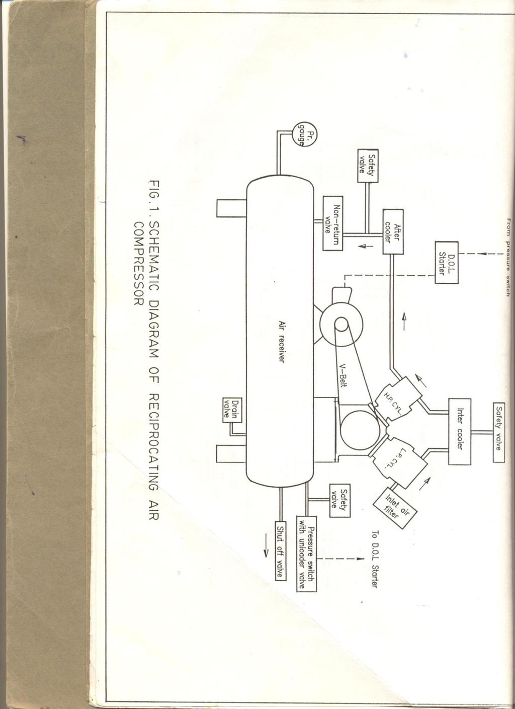
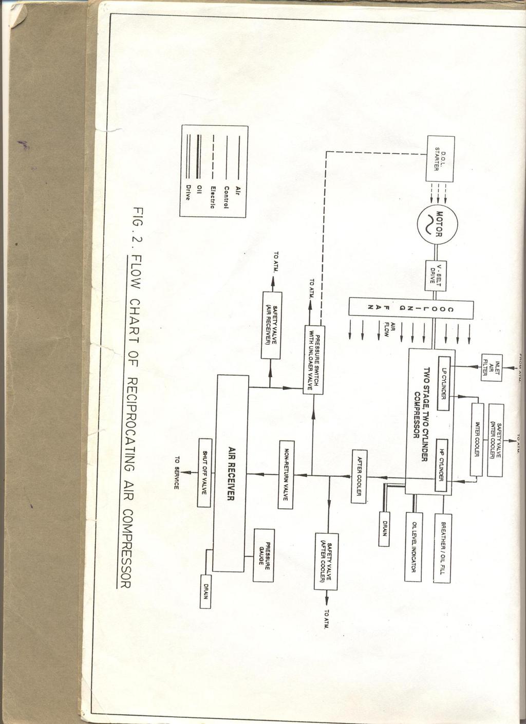
16 PERFORMANCE TEST ON RECIPROCATING AIR COMPRESSOR AIM: To study the working of double stage air compressor and determination of volumetric efficiency, mechanical efficiency. THEORY: When the motor is started, air is sucked from the atmosphere through the inlet air filter and orifice meter and compressed in the LP Cylinder. The hot and compressed air is colled in the intercooler and again compressed in the HP Cylinder.Finnally, high pressure air passes into air receiver tank through after coller and non-return valve. The compressor motor unit consists of a AC motor. The AC motor body frame is mounted on trunnion bearing which swivels on application of load/torque on the motor. The torque/load developed is measured at the torque arm of 0.2m using a spring balance. The encoders (speed pick-ups) are provided for both motor and compressor shafts for measurement of RPM. A toggle switch and digital RPM indicator are provided in the control panel The control console consists of digital speed indicator, temperature indicator, double column manometer for air flow measurement, pressure gauges for pressure rise measurement after each stage separately,energy meter to measure electrical input to the motor. The neccssary mains ON indicators and switches are provided for completeness of the instrumentation. The complete unit is built-in. Foundation is not neccssary for installation of the test rig. The pressure tappings and temperature sensors after each stage are connected to pressure gauges and indicators in the control panel. Air volume measuring chamber with orifice of 15mm diameter is fixed beneath the control console and tappings connected to double column manometer for air intake measurements. PROCEDURE; 1. Release the pressure of air fully from tank, if previously pressurized. 2. Check zero level in the double column. 3. Switch ON the mains and observe the light indicators ON. 4. Keep the outlet valve closed. 5. Switch-ON the starter and allow motor to run full speed.
17 6. As the pressure in the receiver tank increases, set the pressure by obtaining the delivery valve to 1,2,3 Kg/ cm 2 as observed from the pressure gauge and note the readings. 7. Note down the flow rate manometer readings at different pressures. 8. Note down pressure after LP cylinder, after HP cylinder, temperatures after LP cylinder, after inter cooler, after HP cylinder and at the inlet. 9. Note down the energy meter reading, speed and air temperature. 10. Tabulate the above readings as shown. 11. Stop the compressor and release the pressure from the tank after the experiment is completed. OBSERVATIONS: T1= Air inlet temperature T2= After first stage T3=After inter cooler T4=After second Stage E.M Constant=150 Rev/ KWH Orifice Dia=15mm Torque arm=0.2m
18 Sl. No P 1 (LP) Pressure after first stage in Kg/ cm 2 P 2 (HP) Pressure after second stage in Kg/ cm 2 Energy meter reading No.of revns./ Time in Secs. Air flow across Orifice in mm of water h w RPM of compre ssor RPM of motor Swinging field Spring balance readings inkg Temperature Points T1 T2 T3 T CALCULATIONS: 1. Density of Air at 30 C (δa) = Kg/ m 3 2. Water Density (δw) = 1000 Kg/ m 3 3. Acceleration due to gravity,g = 9.81 m/sec 2 4. Orifice diameter = 15 mm 5. Co-efficient of discharge of orifice, C d = Torque arm distance = 0.2m 7. INPUT TO COMPRESSOR =Energy meter reading Wa Q H 8. COMPRESSOR OUTPUT = 736 Where, Wa = Kg/ m 3 = N/ m 3 P H(Head in meters of water) = x 10 4 Wa P is read on after HP cylinder pressure in Kg/ cm x = x x hp t ( where t is time in Secs.for 5 revns)
19 Q (Flow rate) = C d A 2 g Ha m 3 / sec A (Area of orifice) = 4 x d 2 = x 10-4 m 2 hw Ha = 1000 w a 1 = h w Q = 0.62 x1.766 x 10-4 m 2 x Q = x10-4 x h w 2 x 9.81 x hw Where h w = Head measured in mm of water across orifice plate. 9. % EFFICIENCY OF COMPRESSOR (MECHANICAL) % η compressor = Compressor output Electrical input x SWEPT VOLUME OF PISTON (LP) = Area of Piston x Stroke V s1 = 4 x (0.07)2 x = x 10-4 m SWEPT VOLUME OF PISTON (LP) = Area of Piston x Stroke V s2 = 4 x (0.05)2 x = x 10-4 m 3 V s = V s1 + V s2 12. ACTUAL AIR SWEPT Va = Q x 60 RPM of compressor m 3 13.VOLUMETRIC EFFICIENCY % η V = V V a s x 100
20 Sl.No Electrical Input in HP 1 Discharge Q In m3/sec H In mts of air Compressor Output in HP Theoretical swept volume Actual swept volume % efficiency (Mechanical) % volumetric efficiency RESULT: Volumetric efficiency, mechanical efficiency of double stage air compressor is calculated.
21
22
23 PORT TIMING DIAGRAM OF A 2-STROKE PETROL ENGINE AIM: To draw the port timing diagram of a 2-stroke petrol engine by studying given out section model THEORY: Port timing diagram is a graphical representation of exact model is the sequence of operations at which inlet exhaust and transfer port open and closes as well as firing of fuel. It is generally exposed in terms of angular position of crank shaft. In theoretical port timing diagram of 2-stroke petrol engine. The fuel is fired at A i.e., spark advances takes places from TDC to BDC at B both inlet & exhaust ports are open and motion as well as exhaust port are takes place from B to C position moves first to BDC and then slightly upwards to C. Both the plate s parts are closed and compression takes place from C to A. The crank shaft revolves through appproximately and piston moves to TDC in 2-stroke engine crank revolves through In actual port timing diagram the expansion of the change starts as position of piston moves from TDC towards BDC first of all burnt gases leaving the cylinders after a small revolution of crank revolution. The transfer port also opens and fresh fuel air mixture center into engine cylinder now piston reaches BDC and then starts moving up wards. As crank moves a little and BDC. The first transfer port closes and then exhaust port closes. Now the change is compressed with both parts closed & then ignited with help of spark plug before the end of compression stroke. This is done as the change required same time to ignite by the time position reaches to TDC. The burnt gasses push the position downwards with fire and the expansion of burnt gasses takes place opens and close at equal angle on either side of BDC position. TPC: Transfer port closed 64 0 after BDC EPC: Exhaust port closed 83 0 after BDC EPO: Exhaust port opens 68 0 before BDC TPO: Transfer port opens 48 0 before BDC
24 PROCEDURE: 1. First observe the various parts of a 2-stroke petrol engine at given section model 2. Now set up the pointer which placed on the flywheel to 0 0 and position at BDC 3. Slowly move the flywheel after some time before reaching TDC. Then inlet port opens measure of angle at which pointer shows 4. The inlet port opens at 30 0 before TDC. now position reaches TDC and BDC the inlet valve closes 70 0 before BDC 5. The spark advance takes places 45 0 before TDC the exhaust port closes at800 after BDC and transfer port closes at 60 0 after BDC 6. Now position moves from TDC towards BDC suction and compression starts in previous stroke which the piston reaches BDC. And again inlet port closer at 70 0 before BDC 7. Transfer port is closed at 60 0 after BDC and and exhaust port closes at 80 0 after BDC RESULT: 1. Scavenging suction process covered = 2. Compression process covered= 3. Expansion process covered= 4. Exhaust process covered=
25
26 VALVE TIMING DIAGRAM OF 4-STROKE DISEL ENGINE AIM: To draw the valve timing diagram of 4-stroke engine by studying the cut section model THEORY: 1. The Theoretical valve timing diagram for 4-stroke diesel engine is shown in figure. In this the diagram inlet valve opens at A. 2. The solution takes place from A to B. The crank shaft revolves through & the piston moves from TDC to BDC. 3. It B the inlet valve closes and the compression revolves through and the piston moves from BD to TDC. 4. A C the fuel injection takes places i.e. injection valve opens and fuel is fixed by the compression IVO: Inlet Valve open IVC: Inlet valve close FVO: Fuel valve open FVC: Fuel valve close EVO: Exhaust valve open EVC: Exhaust valve close PROCEDURE: 1. Observe the various parts of4-stroke diesel engine and various strokes of engine. After this set the pointer at flywheel at zero 2. Now position at BDC on moving slowly the flywheel inlet valve opens before the position reaching to TDC. Reading are noted 3. Inlet valve opens before TDC and after slowly moved flywheel in the same direction. The position reaches TDC and then BDC 4. After BDC the inlet valve closes note the position of the inlet valve closes 13 0 after BDC 5. Slowly move the flywheel in same direction after closing of inlet valve suction stroke is completed
27 6. Exhaust valve is opens at 35 0 before BDC exhaust valve closes 8 0 after TDC. Same time exhaust stroke completes and cycle is completed PRECAUTIONS: 1. Readings should be taking without parallax error 2. Observe carefully the valves are closed or in open RESULT: The valve timing diagram of 4-stroke diesel engine is studied with the help of given cut section model 1. Suction covered = 2. Compression covered = 3. Expansion covered = 4. Exhaust covered = 5. Overlap =
28
29 DIS-ASSEMBLY AND ASSEMBLY OF A ENGINE. AIM: To study the procedure for dis-assembly and assembly of a specific engine by making a practical trail on it. THEORY: The main parts of any engine are, Cylinder Block: 1. It forms the basic frame work of the engine. 2. It houses the engine cylinders. 3. Serves as bearing or support and guides the piston reciprocating in it. 4. Block contains passengers for circulation of cooling water and lubricating oil. There are two types of rings a) Compression ring b) Oil control ring Connecting rod: It connects the piston with the crank shaft thus facilitative the transmission of power combustion chamber to the crank shaft it also converts the reciprocating motion of the piston into rotary motion of crank shaft. Fly wheel: The fly wheel absorbs the energy power source and gives out this energy the other 3-strokes keeping the crank shaft rotating at uniform speed through out. Cam shaft : A shaft is responsible for opening the valves on addition the crank shaft operates. Cylinder head: 1. The head is a mano block casting. 2. It contains spark plug notes and cooling water Sackets, valve opening mechanism is mounted. 3. Complete valve opening mechanism is mounted on the head.
30 Piston: The top of the piston is called head or crown it may be either done are may specially to form a desired shape of combustion chamber jointly with the cylinder block. Piston pin: It provides a seal b/w the piston fuel pump. Oil pump and distributor valves. Valves: These are accurate by the cams which in turn are operated by crank shaft and perform following functions. PROCEDURE FOR ENGINE DIS-ASSEMBLY. For dis-assembly the engine,it should be mounted in a suitable stand.engine disassembly is carried out in a sequence as follows and engine is out of the vehicle and all the accessories have been removed and oil has been drained. Remove water pump. Remove exhaust manifold Remove oil filter Remove water outlet fitting Remove thermostat Remove crank shaft pulley Remove oil pump Remove crank case ventilation valve Remove rocker arm assembly Remove cylinder head. Remove oil pan. Remove piston rod and connecting rod. Remove timing gear cover. Remove front end plate. Remove fly wheel housing. Remove fly wheel, clutch Remove crank shaft. Remove exhaust valve and springs.
31 Remove cam shaft, valve tappers. Remove oil gallery plugs. PROCEDURE FOR ENGINE DIS-ASSEMBLY. First clean the cylinder block with fresh oils. Piston is connected to connecting rod with gudge pin.this piston have the piston rings. After fixing the rings piston is inserted in to the cylinder block with help of ring compressor. These rings are fitted in the piston grooves with help of calipers. The crank shaft has been placed on the bottom of the cylinder block the connecting rod is connected to its crank. The fly wheel is attached to the crank shaft one side. On the other side of the crank shaft timing gear is fitted. It is for valve operating. This equipment is placed on the sump of the engine. After fixing on the sump the cam shafts are fitted in the cylinder head in the inlet valve & exhaust valves are fitted with help of G-clamp To this cylinder the intake manifold and injectors are fitted one side. Other side of the cylinder head the exhaust manifold is fitted. Fill the sump with new oil. After fill up the oil the water pump is fitted. The thermostat is also fitted to this engine then the re assembly of the given engine is completed. RESULT: Thus the procedure of the assembling of a engine is studied and recorded.
LABORATORY MANUAL I. C. ENGINES & GAS TURBINES (ME-317-E)
") LABORATORY MANUAL I. C. ENGINES & GAS TURBINES (ME-317-E) LIST OF EXPERIMENTS S.No. Name of the Experiment 1. To study the constructional details & working principles of two-stroke petrol/ four-stroke
LABORATORY MANUAL I. C. ENGINES & GAS TURBINES (ME-317-E) LIST OF EXPERIMENTS S.No. Name of the Experiment 1. To study the constructional details & working principles of two-stroke petrol/ four-stroke
SINGLE CYLINDER FOUR STROKE PETROL ENGINE TEST RIG WITH EDDY CURRENT DYNAMOMETER
 SINGLE CYLINDER FOUR STROKE PETROL ENGINE TEST RIG WITH EDDY CURRENT DYNAMOMETER AIM: Conducting a performance test on the engine. DESCRIPTION The Eddy current Dynamometer is coupled to the Engine and
ICAL ENG LAB MANUAL. Dharmapuri Regulation : 2013 Branch : B.E. - Mechanical Engineering Year & Semester: II Year / IV Semester VVIT
 Dharmapuri 636 703 LAB MANUAL Regulation : 2013 Branch : B.E. - Mechanical Engineering Year & Semester: II Year / IV Semester ME6412 -THERMAL ENGINEERING LABORATORY - I ICAL ENG 1 GENERAL INSTRUCTION All
Comparative Study Of Four Stroke Diesel And Petrol Engine.
 Comparative Study Of Four Stroke Diesel And Petrol Engine. Aim: To study the construction and working of 4- stroke petrol / diesel engine. Theory: A machine or device which derives heat from the combustion
UNIT 2 POWER PLANTS 2.1 INTRODUCTION 2.2 CLASSIFICATION OF IC ENGINES. Objectives. Structure. 2.1 Introduction
 UNIT 2 POWER PLANTS Power Plants Structure 2.1 Introduction Objectives 2.2 Classification of IC Engines 2.3 Four Stroke Engines versus Two Stroke Engines 2.4 Working of Four Stroke Petrol Engine 2.5 Working
SHRI SHANKARACHARYA INSTITUTE OF PROFESSIONAL MANAGEMENT AND TECHNOLOGY LAB MANUAL INTERNAL COMBUSTION ENGINES MECHANICAL ENGINEERING DEPARTMENT
 SHRI SHANKARACHARYA INSTITUTE OF PROFESSIONAL MANAGEMENT AND TECHNOLOGY LAB MANUAL INTERNAL COMBUSTION ENGINES MECHANICAL ENGINEERING DEPARTMENT LAB MANUAL INTERNAL COMBUSTION ENGINES 1. ) AIM : Study
SAMPLE STUDY MATERIAL
 IC Engine - ME GATE, IES, PSU 1 SAMPLE STUDY MATERIAL Mechanical Engineering ME Postal Correspondence Course Internal Combustion Engine GATE, IES & PSUs IC Engine - ME GATE, IES, PSU 2 C O N T E N T 1.
UNIT IV INTERNAL COMBUSTION ENGINES
 UNIT IV INTERNAL COMBUSTION ENGINES Objectives After the completion of this chapter, Students 1. To know the different parts of IC engines and their functions. 2. To understand the working principle of
SHREE RAMCHANDRA EDUCATION SOCIETY S LONIKAND, PUNE DEPARTMENT OF MECHANICAL ENGINEERING LAB MANUAL. Applied Thermodynamics (ATD) Semester-IV
 Semester-IV") SHREE RAMCHANDRA EDUCATION SOCIETY S SHREE RAMCHANDRA COLLEGE OF ENGINEERING, LONIKAND, PUNE 412 216 DEPARTMENT OF MECHANICAL ENGINEERING LAB MANUAL Applied Thermodynamics (ATD) Semester-IV Prepared by
SHREE RAMCHANDRA EDUCATION SOCIETY S SHREE RAMCHANDRA COLLEGE OF ENGINEERING, LONIKAND, PUNE 412 216 DEPARTMENT OF MECHANICAL ENGINEERING LAB MANUAL Applied Thermodynamics (ATD) Semester-IV Prepared by
AIM OF THE EXPERIMENT:- To study about two stroke and four stroke petrol engines. APPARATUS REQUIRED:- Sl.no Name of the apparatus Specification Quant
 EXPERIMENT ON TWO STROKE AND FOUR STROKE PETROL ENGINES Prepared By Prof. (Dr.) M. K. Roul Professor and Principal, Gandhi Institute for Technological Advancement (GITA), Bhubaneswar 752054 June 2014 1
I.C ENGINES. CLASSIFICATION I.C Engines are classified according to:
 I.C ENGINES An internal combustion engine is most popularly known as I.C. engine, is a heat engine which converts the heat energy released by the combustion of the fuel taking place inside the engine cylinder
(v) Cylinder volume It is the volume of a gas inside the cylinder when the piston is at Bottom Dead Centre (B.D.C) and is denoted by V.
 Cylinder volume It is the volume of a gas inside the cylinder when the piston is at Bottom Dead Centre (B.D.C) and is denoted by V.") UNIT II GAS POWER CYCLES AIR STANDARD CYCLES Air standard cycles are used for comparison of thermal efficiencies of I.C engines. Engines working with air standard cycles are known as air standard engines.
UNIT II GAS POWER CYCLES AIR STANDARD CYCLES Air standard cycles are used for comparison of thermal efficiencies of I.C engines. Engines working with air standard cycles are known as air standard engines.
Introduction to I.C Engines CH. 1. Prepared by: Dr. Assim Adaraje
 Introduction to I.C Engines CH. 1 Prepared by: Dr. Assim Adaraje 1 An internal combustion engine (ICE) is a heat engine where the combustion of a fuel occurs with an oxidizer (usually air) in a combustion
2. Discuss the effects of the following operating variables on detonation
 Code No: RR220303 Set No. 1 II B.Tech II Semester Regular Examinations, Apr/May 2006 THERMAL ENGINEERING-I ( Common to Mechanical Engineering and Automobile Engineering) Time: 3 hours Max Marks: 80 Answer
MAHARASHTRA STATE BOARD OF TECHNICAL EDUCATION (Autonomous) Summer 15 EXAMINATION Subject Code: Model Answer Page No: 1/18
 Summer 15 EXAMINATION Subject Code: Model Answer Page No: 1/18") Subject Code: 708 Model Answer Page No: /8 Important Instructions to examiners: ) The answers should be examined by key words and not as word-to-word as given in the model answer scheme. ) The model answer
Subject Code: 708 Model Answer Page No: /8 Important Instructions to examiners: ) The answers should be examined by key words and not as word-to-word as given in the model answer scheme. ) The model answer
Applied Thermodynamics Internal Combustion Engines
 Applied Thermodynamics Internal Combustion Engines Assoc. Prof. Dr. Mazlan Abdul Wahid Faculty of Mechanical Engineering Universiti Teknologi Malaysia www.fkm.utm.my/~mazlan 1 Coverage Introduction Operation
ENGINE & WORKING PRINCIPLES
 ENGINE & WORKING PRINCIPLES A heat engine is a machine, which converts heat energy into mechanical energy. The combustion of fuel such as coal, petrol, diesel generates heat. This heat is supplied to a
WINTER -14 EXAMINATION Subject Code: Model Answer Page No: 1/22
 (ISO/IEC - 700-005 Certified) WINTER - EXAMINATION Subject Code: 708 Model Answer Page No: / Important Instructions to examiners: ) The answers should be examined by key words and not as word-to-word as
VALVE TIMING DIAGRAM FOR SI ENGINE VALVE TIMING DIAGRAM FOR CI ENGINE
 VALVE TIMING DIAGRAM FOR SI ENGINE VALVE TIMING DIAGRAM FOR CI ENGINE Page 1 of 13 EFFECT OF VALVE TIMING DIAGRAM ON VOLUMETRIC EFFICIENCY: Qu. 1:Why Inlet valve is closed after the Bottom Dead Centre
PORT TIMING DIAGRAM OF SINGLE CYLINDER TWO STROKE SPARK IGNITION ENGINE
 AIM: PORT TIMING DIAGRAM OF SINGLE CYLINDER TWO STROKE SPARK IGNITION ENGINE To draw the port timing diagram of a two stroke spark ignition engine. APPARATUS REQUIRED: 1. A two stroke petrol engine 2.
ADDIS ABABA UNIVERSITY INSTITUTE OF TECHNOLOGY
 1 INTERNAL COMBUSTION ENGINES ADDIS ABABA UNIVERSITY INSTITUTE OF TECHNOLOGY MECHANICAL ENGINEERING DEPARTMENT DIVISON OF THERMAL AND ENERGY CONVERSION IC Engine Fundamentals 2 Engine Systems An engine
MAHARASHTRA STATE BOARD OF TECHNICAL EDUCATION (Autonomous) Winter 15 EXAMINATION Subject Code: Model Answer Page No: 1/26
 Winter 15 EXAMINATION Subject Code: Model Answer Page No: 1/26") (ISO/IEC - 700-005 Certified) Winter 5 EXAMINATION Subject Code: 708 Model Answer Page No: /6 Important Instructions to examiners: ) The answers should be examined by key words and not as word-to-word
(ISO/IEC - 700-005 Certified) Winter 5 EXAMINATION Subject Code: 708 Model Answer Page No: /6 Important Instructions to examiners: ) The answers should be examined by key words and not as word-to-word
ENGINES ENGINE OPERATION
 ENGINES ENGINE OPERATION Because the most widely used piston engine is the four-stroke cycle type, it will be used as the example for this section, Engine Operation and as the basis for comparison in the
FLASH AND FIRE POINT (PENSKY MARTENS CLOSED CUP APPARATUS)
") EXPERIMENT NO: 1 FLASH AND FIRE POINT (PENSKY MARTENS CLOSED CUP APPARATUS) Conduct an experiment to determine the Flash point and Fire point of a given oil using Pensky Martens closed cup apparatus AIM:
EXPERIMENT NO: 1 FLASH AND FIRE POINT (PENSKY MARTENS CLOSED CUP APPARATUS) Conduct an experiment to determine the Flash point and Fire point of a given oil using Pensky Martens closed cup apparatus AIM:
THERMAL ENGINEERING LABORATORY MANUAL
 THERMAL ENGINEERING LAB MANUAL BALAJI INSTITUTE OF TECHNOLOGY AND SCIENCE LAKNEPALLY (V), NARSAMPET (M), WARANGAL-506331 THERMAL ENGINEERING LABORATORY MANUAL DEPARTMENT OF MECHANICAL ENGINEERING NUSRATH
 SET - 1 II B. Tech II Semester Regular/Supplementary Examinations, April/May-2017 THERMAL ENGINEERING-I (Mechanical Engineering) Time: 3 hours Max. Marks: 70 Note: 1. Question Paper consists of two parts
B.Tech. - VIEP - MECHANICAL ENGINEERING (BTMEVI) Term-End Examination June 2016
 Term-End Examination June 2016") No. of Printed Pages : 5 I BIME-010 I B.Tech. - VIEP - MECHANICAL ENGINEERING (BTMEVI) 00 1 Ems, Term-End Examination June 2016 BIME-010 : THERMAL ENGINEERING Time : 3 hours Maximum Marks : 70 Note : Attempt
No. of Printed Pages : 5 I BIME-010 I B.Tech. - VIEP - MECHANICAL ENGINEERING (BTMEVI) 00 1 Ems, Term-End Examination June 2016 BIME-010 : THERMAL ENGINEERING Time : 3 hours Maximum Marks : 70 Note : Attempt
CHAPTER I GAS POWER CYCLES
 CHAPTER I GAS POWER CYCLES 1.1 AIR STANDARD CYCLES Air standard cycles are used for comparison of thermal efficiencies of I.C engines. Engines working with air standard cycles are known as air standard
Please welcome for any correction or misprint in the entire manuscript and your valuable suggestions kindly mail us
 Problems of Practices Of Basic and Applied Thermodynamics I. C. Engine Prepared By Brij Bhooshan Asst. Professor B. S. A. College of Engg. And Technology Mathura, Uttar Pradesh, (India) Supported By: Purvi
The Four Stroke Cycle
 1 Induction As the piston travels down the cylinder it draws filtered air at atmospheric pressure and ambient temperature through an air filter and inlet valves into the cylinder. 2 Compression When the
CHAPTER 2 : ESSENTIAL CHARACTERISTICS OF THE VEHICLE AND ENGINE AND INFORMATION CONCERNING THE CONDUCT OF TESTS
 CHAPTER 2 : ESSENTIAL CHARACTERISTICS OF THE VEHICLE AND ENGINE AND INFORMATION CONCERNING THE CONDUCT OF TESTS 1.0 Description of the Vehicle - 1.1 Trade name or mark of the vehicle - 1.2 Vehicle type
MODEL ANSWER WINTER 18 EXAMINATION 17408
 Important Instructions to examiners: 1) The answers should be examined by key words and not as word-to-word as given in themodel answer scheme. 2) The model answer and the answer written by candidate may
Template for the Storyboard stage
 Template for the Storyboard stage Animation can be done in JAVA 2-D. Mention what will be your animation medium: 2D or 3D Mention the software to be used for animation development: JAVA, Flash, Blender,
Assignment-1 Air Standard Cycles
 Assignment-1 Air Standard Cycles 1. What do u mean by air standard cycle? List assumptions for air standard cycle & give reasons why air standard cycle differs from actual cycle. 2. Derive an equation
MAHARASHTRA STATE BOARD OF TECHNICAL EDUCATION
 Subject Code: 708 Model Answer Page No: / Important Instructions to examiners: ) The answers should be examined by key words and not as word-to-word as given in the model answer scheme. ) The model answer
Internal Combustion Engine. Prepared by- Md Ferdous Alam Lecturer, MEE, SUST
 Internal Combustion Engine Prepared by- Md Ferdous Alam Lecturer, MEE, SUST What is an Engine? -a machine designed to convert one form of energy into mechanical energy Two types of engines : 1. Internal
BHARATHIDASAN ENGINEERING COLLEGE
 BHARATHIDASAN ENGINEERING COLLEGE NATTRAMPALLI 635 854 DEPARTMENT OF MECHANICAL ENGINEERING LABORATORY MANUAL ME6412 THERMAL ENGINEERING LABORATORY - I YEAR / SEMESTER : II / IV DEPARTMENT : Mechanical
CHAPTER-3 EXPERIMENTAL SETUP. The experimental set up is made with necessary. instrumentations to evaluate the performance, emission and
 95 CHAPTER-3 EXPERIMENTAL SETUP The experimental set up is made with necessary instrumentations to evaluate the performance, emission and combustion parameters of the compression ignition engine at different
4 Stroke Diesel. Oil type SAE 15 W40/E 3
 MARCH 2006 TECHNICAL DATA 2.33 GENERAL SPECIFICATIONS Cycle Air supply Injection 4 Stroke Diesel naturally aspirated direct Number of cylinders 4 in line 6 in line Bore mm 104 Stroke mm 132 Total displacement
TKP3501 Farm Mechanization
 TKP3501 Farm Mechanization Topic 2: Internal Combustion Engines Ahmad Suhaizi, Mat Su Email: asuhaizi@upm.edu.my Outlines Internal vs external combustion engines Engine structure Combustion cycle 4 stroke
10/29/2018. Chapter 16. Turning Moment Diagrams and Flywheel. Mohammad Suliman Abuhaiba, Ph.D., PE
 1 Chapter 16 Turning Moment Diagrams and Flywheel 2 Turning moment diagram (TMD) graphical representation of turning moment or crank-effort for various positions of the crank 3 Turning Moment Diagram for
CHAPTER 2 : ESSENTIAL CHARACTERISTICS OF THE VEHICLE AND ENGINE AND INFORMATION CONCERNING THE CONDUCT OF TESTS
 CHAPTER 2 : ESSENTIAL CHARACTERISTICS OF THE VEHICLE AND ENGINE AND INFORMATION CONCERNING THE CONDUCT OF TESTS 1.0 Description of the Vehicle - 1.1 Trade name or mark of the vehicle - 1.2 Vehicle type
Kul Internal Combustion Engine Technology. Definition & Classification, Characteristics 2015 Basshuysen 1,2,3,4,5
 Kul-14.4100 Internal Combustion Engine Technology Definition & Classification, Characteristics 2015 Basshuysen 1,2,3,4,5 Definitions Combustion engines convert the chemical energy of fuel to mechanical
Automobile section, showing different parts in detail. and miscellaneous devices.
 SECTION VII Nos. 97 112 Automobile section, showing different parts in detail. and miscellaneous devices. Hydraulic jack MECHANICAL MODELS 43 Section VII 97. Automobile engine starter. This device known
AME 436. Energy and Propulsion. Lecture 6 Unsteady-flow (reciprocating) engines 1: Basic operating principles, design & performance parameters
 engines 1: Basic operating principles, design & performance parameters") AME 436 Energy and Propulsion Lecture 6 Unsteady-flow (reciprocating) engines 1: Basic operating principles, design & performance parameters Outline Classification of unsteady-flow engines Basic operating
AME 436 Energy and Propulsion Lecture 6 Unsteady-flow (reciprocating) engines 1: Basic operating principles, design & performance parameters Outline Classification of unsteady-flow engines Basic operating
INTRODUCTION OF FOUR STROKE ENGINE
 INTRODUCTION OF FOUR STROKE ENGINE Engine: An engine is motor which converts chemical energy into mechanical energy Fuel/petrol engine: A petrol engine (known as a gasoline engine in North America) is
MODEL ANSWER Summer 17 EXAMINATION
 Important Instructions to examiners: 1) The answers should be examined by key words and not as word-to-word as given in the model answer scheme. 2) The model answer and the answer written by candidate
2013 THERMAL ENGINEERING-I
 SET - 1 II B. Tech II Semester, Regular Examinations, April/May 2013 THERMAL ENGINEERING-I (Com. to ME, AME) Time: 3 hours Max. Marks: 75 Answer any FIVE Questions All Questions carry Equal Marks ~~~~~~~~~~~~~~~~~~~~~~~~
GYANMANJARI INSTITUTE OF TECHNOLOGY (GMIT) SUBJECT: ELEMENTS OF MECHANICAL ENGINEERING Assignment Ch 1
 SUBJECT: ELEMENTS OF MECHANICAL ENGINEERING Assignment Ch 1") 1. 3. GYANMANJARI INSTITUTE OF TECHNOLOGY (GMIT) Assignment Ch 1 A steel ball having mass of 10 kg and a specific heat of 460 J/kg K is heated from 50 o C to 200 o C. Determine the heat required. In a
1. 3. GYANMANJARI INSTITUTE OF TECHNOLOGY (GMIT) Assignment Ch 1 A steel ball having mass of 10 kg and a specific heat of 460 J/kg K is heated from 50 o C to 200 o C. Determine the heat required. In a
Chapter 14 Small Gas Engines
 Chapter 14 Small Gas Engines Use the Textbook Pages 321 349 to help answer the questions Why You Learn So Well in Tech & Engineering Classes 1. Internal combustion make heat by burning a fuel & air mixture
Scheme - G. Sample Test Paper-I. Course Name : Diploma in Mechanical Engineering Course Code : ME Semester : Fifth Subject Title : Power Engineering
 Sample Test Paper-I Marks : 25 Time:1 hour Q1. Attempt any Three 3X3=9 a) Define i) Mean Effective Pressure ii) Piston Speed iii) Swept Volume b) Draw Carnot cycle on P-V and T-S Diagram c) State the need
AME 436. Energy and Propulsion. Lecture 6 Unsteady-flow (reciprocating) engines 1: Basic operating principles, design & performance parameters
 engines 1: Basic operating principles, design & performance parameters") AME 436 Energy and Propulsion Lecture 6 Unsteady-flow (reciprocating) engines 1: Basic operating principles, design & performance parameters Outline Classification of unsteady-flow engines Basic operating
AME 436 Energy and Propulsion Lecture 6 Unsteady-flow (reciprocating) engines 1: Basic operating principles, design & performance parameters Outline Classification of unsteady-flow engines Basic operating
VETRI VINAYAHA COLLEGE OF ENGINEERING AND TECHNOLOGY DEPARTMENT OF MECHANICAL ENGINEERING ME6404 THERMAL ENGINEERING
 VETRI VINAYAHA COLLEGE OF ENGINEERING AND TECHNOLOGY DEPARTMENT OF MECHANICAL ENGINEERING ME6404 THERMAL ENGINEERING UNIT I - GAS POWER CYCLES 1. What is a thermodynamic cycle? Thermodynamic cycle is defined
Principles of Engine Operation. Information
 Internal Combustion Engines MAK 4070E Principles of Engine Operation Prof.Dr. Cem Soruşbay Istanbul Technical University Information Prof.Dr. Cem Soruşbay İ.T.Ü. Makina Fakültesi Motorlar ve Taşıtlar Laboratuvarı
Air Cooled Engine Technology. Roth 9 th Ch 5 2 & 4 Cycle Engines Pages 81 94
 Roth 9 th Ch 5 2 & 4 Cycle Engines Pages 81 94 1. The of the piston is its movement in the cylinder from one end of its travel to another. Either TDC to BDC (downstroke) or BDC to TDC (upstroke). Identified
Evaluation Of Parameters Affecting The Performance Of Spark-Ignition Engine BY Bello Lawal And Dr. Isa Garba
 Evaluation Of Parameters Affecting The Performance Of Spark-Ignition Engine BY Bello Lawal And Dr. Isa Garba ABSTRACT This paper focused on the performance of a spark-ignition (engine, which is affected
(a) then mean effective pressure and the indicated power for each end ; (b) the total indicated power : [16]
![(a) then mean effective pressure and the indicated power for each end ; (b) the total indicated power : [16]](/thumbs/79/80273804.jpg "(a) then mean effective pressure and the indicated power for each end ; (b) the total indicated power : [16]") Code No: R05220304 Set No. 1 II B.Tech II Semester Regular Examinations, Apr/May 2007 THERMAL ENGINEERING-I ( Common to Mechanical Engineering and Automobile Engineering) Time: 3 hours Max Marks: 80 Answer
Code No: R05220304 Set No. 1 II B.Tech II Semester Regular Examinations, Apr/May 2007 THERMAL ENGINEERING-I ( Common to Mechanical Engineering and Automobile Engineering) Time: 3 hours Max Marks: 80 Answer
Combustion engines. Combustion
 Combustion engines Chemical energy in fuel converted to thermal energy by combustion or oxidation Heat engine converts chemical energy into mechanical energy Thermal energy raises temperature and pressure
Noble Group of Institutions, Junagadh. Faculty of Engineering Department of Mechanical Engineering
 Semester:1 st Subject: Elements of Mechanical Engineering (2110006) Faculty: Mr. Ishan Bhatt Year: 2017-18 Class: Comp. & IT Ele TUTORIAL 1 INTRODUCTION Q.1 Define: Force, Work, Pressure, Energy, Heat
Answer. 1 a) Attempt any SIX of the following: 12. i) i) List any four applications of IC Engine 2
 Attempt any SIX of the following: 12. i) i) List any four applications of IC Engine 2") (ISO/IEC - 700-005 Certified) Important Instructions to examiners: ) The answers should be examined by key words and not as word-to-word as given in the model answer scheme. ) The model answer and the
(ISO/IEC - 700-005 Certified) Important Instructions to examiners: ) The answers should be examined by key words and not as word-to-word as given in the model answer scheme. ) The model answer and the
Diesel Engine Power Plants
 Diesel Engine Power Plants Energy Conversion Engineering Diesel Engine Power Plants Introduction Diesel electric plants are generally available in the range of 2 to 50 MW capacity and they can be used
Experimental Investigation on Modification of Inlet poppet valve of single cylinder Direct Ignition Four stroke Diesel Engine
 Experimental Investigation on Modification of Inlet poppet valve of single cylinder Direct Ignition Four stroke Diesel Engine Dr. Hiregoudar Yerrennagoudaru 1, Shiva prasad Desai 2, Mallikarjuna. A 3 1
ENERGY CONVERSION ENGINEERING LAB MANUAL
 PES INSTITUTE OF TECHNOLOGY ENERGY CONVERSION ENGINEERING LAB MANUAL DEPARTMENT OF MECHANICAL ENGINEERING, P E S INSTITUTE OF TECHNOLOGY, BANGALORE SOUTH CAMPUS CONTENTS SL. No. NAME OF THE EXPT. PAGE
AT 2303 AUTOMOTIVE POLLUTION AND CONTROL Automobile Engineering Question Bank
 AT 2303 AUTOMOTIVE POLLUTION AND CONTROL Automobile Engineering Question Bank UNIT I INTRODUCTION 1. What are the design considerations of a vehicle?(jun 2013) 2..Classify the various types of vehicles.
SIDDHARTH INSTITUTE OF ENGINEERING & TECHNOLOGY :: PUTTUR (AUTONOMOUS) QUESTION BANK UNIT I I.C ENGINES
 QUESTION BANK UNIT I I.C ENGINES") SIDDHARTH INSTITUTE OF ENGINEERING & TECHNOLOGY :: PUTTUR UNIT I I.C ENGINES 1 (a) Explain any six types of classification of Internal Combustion engines. (6M) (b) With a neat sketch explain any three
SIDDHARTH INSTITUTE OF ENGINEERING & TECHNOLOGY :: PUTTUR UNIT I I.C ENGINES 1 (a) Explain any six types of classification of Internal Combustion engines. (6M) (b) With a neat sketch explain any three
COVENANT UNIVERSITY NIGERIA TUTORIAL KIT OMEGA SEMESTER PROGRAMME: MECHANICAL ENGINEERING
 COVENANT UNIVERSITY NIGERIA TUTORIAL KIT OMEGA SEMESTER PROGRAMME: MECHANICAL ENGINEERING COURSE: MCE 320 DISCLAIMER The contents of this document are intended for practice and leaning purposes at the
1983 BMW 320i. 1.8L 4-CYL 1983 Engines - 1.8L 4-Cylinder Engines - 1.8L 4-Cylinder
 ENGINE IDENTIFICATION 1.8L 4-CYL 1983 Engines - 1.8L 4-Cylinder For engine repair procedures not covered in this article, see ENGINE OVERHAUL PROCEDURES - GENERAL INFORMATION article in the GENERAL INFORMATION
Al-Balqa Applied University
 تا سست عام 997 Specialization Common Course Number 202073 Course Title Internal Combustion Engines Credit Hours 3 Theoretical Hours 3 Practical Hours 0 صفحة () من (0) تا سست عام 997 Brief Course Description:
Internal combustion engines can be classified in a number of different ways: 1. Types of Ignition
 Chapter 1 Introduction 1-3 ENGINE CLASSIFICATIONS Internal combustion engines can be classified in a number of different ways: 1. Types of Ignition 1 (a) Spark Ignition (SI). An SI engine starts the combustion
SIR C R REDDY COLLEGE OF ENGINEERING ELURU MECHANICAL ENGINEERING LAB-II
 SIR C R REDDY COLLEGE OF ENGINEERING ELURU-534 007 MECHANICAL ENGINEERING LAB-II MANUAL DEPARTMENT OF MECHANICAL ENGINEERING DEPARTMENT OF MECHANICAL ENGINEERING MECHANICAL ENGINEERING LAB-II LIST OF EXPERIMENTS
E/ECE/324/Rev.1/Add.84/Amend.5 E/ECE/TRANS/505/Rev.1/Add.84/Amend.5
 10 May 2010 AGREEMENT CONCERNING THE ADOPTION OF UNIFORM TECHNICAL PRESCRIPTIONSFOR WHEELED VEHICLES, EQUIPMENT AND PARTS WHICH CAN BE FITTED AND/OR BE USED ON WHEELED VEHICLES AND THE CONDITIONS FOR RECIPROCAL
TM &P TECHNICAL MANUAL
 TM 5-3895-355-14&P TECHNICAL MANUAL OPERATOR'S, ORGANIZATIONAL, DIRECT SUPPORT AND GENERAL SUPPORT MAINTENANCE MANUAL (INCLUDING REPAIR PARTS INFORMATION AND SUPPLEMENTAL MAINTENANCE AND REPAIR PARTS INSTRUCTIONS)
Assignment-1 Introduction
 Assignment-1 Introduction 1. Compare S.I. engines with C.I engines. 2. Explain with the help of neat sketch, the working of a 2-stroke petrol engine. 3. Derive an equation of efficiency, work output and
T erm STI2D. The process by which a car works is a lot simpler than you may think. When a driver turns a key in the ignition:
 1. How a car engine Works The process by which a car works is a lot simpler than you may think. When a driver turns a key in the ignition: The car battery powers up sending Power to the starter motor,
IC ENGINES. Differences between SI and CI engines: Petrol is fuel, which has a high self ignition temperature
 IC ENGINES SI Engines work at constant volume. They have a compression ratio of around 6-10. But CI engines work at constant pressure and has a compression ratio of 16-20. In four stroke engines, one power
Internal Combustion Engines
 Engine Cycles Lecture Outline In this lecture we will: Analyse actual air fuel engine cycle: -Stroke cycle -Stroke cycle Compare these cycles to air standard cycles Actual Engine Cycle Although air standard
Two Cycle and Four Cycle Engines
 Ch. 5 Two Cycle and Four Cycle Engines Feb 20 7:43 AM 1 Stroke of the piston is its movement in the cylinder from one end of its travel to the other Feb 20 7:44 AM 2 Four stroke cycle engine 4 strokes
THE FOUR STROKE CYCLE BUT HOW DOES IT WORK EXACTLY? LET S LOOK IN MORE DETAIL 1. INDUCTION SUCK 2. COMPRESSION 3. COMBUSTION 4.
 THE FOUR STROKE CYCLE BUT HOW DOES IT WORK EXACTLY? WE KNOW ABOUT:- WHICH WE KNOW AS:- LET S LOOK IN MORE DETAIL 1. INDUCTION SUCK 2. COMPRESSION 3. COMBUSTION 4. EXHAUST SQUEEZE BANG BLOW Inlet valve
ACTUAL CYCLE. Actual engine cycle
 1 ACTUAL CYCLE Actual engine cycle Introduction 2 Ideal Gas Cycle (Air Standard Cycle) Idealized processes Idealize working Fluid Fuel-Air Cycle Idealized Processes Accurate Working Fluid Model Actual
AT AUTOMOTIVE ENGINES QUESTION BANK
 AT6301 - AUTOMOTIVE ENGINES QUESTION BANK UNIT I: CONSTRUCTION & WORKING PRINCIPLE OF IC ENGINES 1. State the application of CI engines? 2. What is Cubic capacity of an engine? 3. What is the purpose of
California State University, Bakersfield. Signals and Systems. Kristin Koehler. California State University, Bakersfield Lecture 4 July 18 th, 2013
 Kristin Koehler California State University, Bakersfield Lecture 4 July 18 th, 2013 1 Outline Internal combustion engines 2 stroke combustion engines 4 stroke combustion engines Diesel engines 2 Consists
Elements of Mechanical Engineering (EME) QUESTIONS
 QUESTIONS") QUESTIONS 1) In First angle projection method (a) Plan comes above elevation (b) Plan comes below elevation (c) Plan comes besides elevation (d) Plan is on the left hand side. (2) Where LHSV in third angle
QUESTIONS 1) In First angle projection method (a) Plan comes above elevation (b) Plan comes below elevation (c) Plan comes besides elevation (d) Plan is on the left hand side. (2) Where LHSV in third angle
Approved by AICTE, Government of India & affiliated to Dr. A.P.J. Abdul Kalam Technical University, Lucknow Department of Mechanical Engineering
 Experiment No. - 1 Object: Study and working of four stroke petrol engine. Apparatus Required: S. No. Name of Apparatus Specifications Model of Four stroke petrol engine NA Figure 1: Working of four stroke
Engine Systems. Basic Engine Operation. Firing Order. Four Stroke Cycle. Overhead Valves - OHV. Engine Design. AUMT Engine Systems 4/4/11
 Advanced Introduction Brake to Automotive Systems Diagnosis Service and Service Basic Engine Operation Engine Systems Donald Jones Brookhaven College The internal combustion process consists of: admitting
CHAPTER 1 MECHANICAL ARRANGEMENT
 CHAPTER 1 CHAPTER 1 MECHANICAL ARRANGEMENT CONTENTS PAGE Basic Principals 02 The Crankshaft 06 Piston Attachment 08 Major Assemblies 10 Valve Gear 12 Cam Drive 18 Mechanical Arrangement - Basic Principals
New Polytechnic, Kolhapur
 01. Fundamentals of I.C. Engine 01. Fundamentals of I.C. Engine 16 marks Content 1.1 Introduction 4 Marks Definition of I C engine. Engine nomenclature. 1.2 The working principle of Engine 6 Marks Four-Stroke
TECHNICAL MANUAL ORGANIZATIONAL, DIRECT SUPPORT AND GENERAL SUPPORT MAINTENANCE MANUAL (INCLUDING REPAIR PARTS LIST AND SPECIAL TOOLS LIST) FOR
 FOR") TECHNICAL MANUAL ORGANIZATIONAL, DIRECT SUPPORT AND GENERAL SUPPORT MAINTENANCE MANUAL (INCLUDING REPAIR PARTS LIST AND SPECIAL TOOLS LIST) FOR CRANE, TRUCK MOUNTED HYDRAULIC 25 TON (CCE) GROVE MODEL TM
TECHNICAL MANUAL ORGANIZATIONAL, DIRECT SUPPORT AND GENERAL SUPPORT MAINTENANCE MANUAL (INCLUDING REPAIR PARTS LIST AND SPECIAL TOOLS LIST) FOR CRANE, TRUCK MOUNTED HYDRAULIC 25 TON (CCE) GROVE MODEL TM
FUNDAMENTAL OF AUTOMOBILE SYSTEMS
 Prof. Kunalsinh Mechanical Engineering Dept. FUNDAMENTAL OF AUTOMOBILE SYSTEMS Prof. Kunalsinh kathia [MECHANICAL DEPT.] UNIT-2 [ENGINES] PART-1 Prof. Kunalsinh kathia [MECHANICAL DEPT.] Internal combustion
KINGS COLLEGE OF ENGINEERING DEPARTMENT OF MECHANICAL ENGINEERING. Question Bank. UNIT-I THERMODYNAMIC CYCLES Part-A (2 Marks)
") KINGS COLLEGE OF ENGINEERING DEPARTMENT OF MECHANICAL ENGINEERING Question Bank Sub. Code/Name: ME1351 - THERMAL ENGINEERING Year/Sem: III/VI 1. What is a thermodynamic cycle? UNIT-I THERMODYNAMIC CYCLES
KINGS COLLEGE OF ENGINEERING DEPARTMENT OF MECHANICAL ENGINEERING Question Bank Sub. Code/Name: ME1351 - THERMAL ENGINEERING Year/Sem: III/VI 1. What is a thermodynamic cycle? UNIT-I THERMODYNAMIC CYCLES
Internal Combustion Engines
 Internal Combustion Engines The internal combustion engine is an engine in which the burning of a fuel occurs in a confined space called a combustion chamber. This exothermic reaction of a fuel with an
Natural Gas Engine E 0836 E 302 Technical Data
 Page 1 Principle: 4-stroke Otto gas engine No of cylinders : 6 in line Engine cooling : Without engine water pump, coolant to be circulated by external water pump with temperature control. Lubrication
 Important Instructions to examiners: 1) The answers should be examined by key words and not as word-to-word as given in the model answer scheme. 2) The model answer and the answer written by candidate
CHAPTER -3 EXPERIMENTAL SETUP AND TEST PROCEDURE
 94 CHAPTER -3 EXPERIMENTAL SETUP AND TEST PROCEDURE 95 CHAPTER 3 CHAPTER 3: EXPERIMENTAL SETUP AND TEST PROCEDURE S.No. Name of the Sub-Title Page No. 3.1 Introduction 97 3.2 Experimental setup 100 3.2.1
CHAPTER 4 VARIABLE COMPRESSION RATIO ENGINE WITH DATA ACQUISITION SYSTEM
 57 CHAPTER 4 VARIABLE COMPRESSION RATIO ENGINE WITH DATA ACQUISITION SYSTEM 4.1 GENERAL The variable compression ratio engine was developed by Legion brothers, Bangalore, India. This chapter briefly discusses
Channabasaveshwara Institute of Technology. (An ISO 9001:2008 Certified Institution) NH 206 (B.H. Road), Gubbi, Tumkur Karnataka.
 NH 206 (B.H. Road), Gubbi, Tumkur Karnataka.") Channabasaveshwara Institute of Technology (An ISO 9001:2008 Certified Institution) NH 206 (B.H. Road), Gubbi, Tumkur 572 216. Karnataka. QMP 7.1 D/F Department of Mechanical Engineering LAB MANUAL (2017-18)
Channabasaveshwara Institute of Technology (An ISO 9001:2008 Certified Institution) NH 206 (B.H. Road), Gubbi, Tumkur 572 216. Karnataka. QMP 7.1 D/F Department of Mechanical Engineering LAB MANUAL (2017-18)
THERMODYNAMICS. T85D - Internal Combustion Engine Test Bed
 THERMODYNAMICS T85D - Internal Combustion Engine Test Bed 1. General Didacta s T85D Internal Combustion Engine Test Bed has been specially designed for use in testing laboratories, and to ensure the greatest
IC ENGINE(4 STROKE) G.H.R.I.E&M JALGAON. Sec.(Mech) Sec.(Mech) Sec.(Mech) Sec.(Mech) Mehta chirag Shah sagar Patel jainish talele amit
 G.H.R.I.E&M JALGAON. Sec.(Mech) Sec.(Mech) Sec.(Mech) Sec.(Mech) Mehta chirag Shah sagar Patel jainish talele amit") IC ENGINE(4 STROKE) G.H.R.I.E&M JALGAON Mehta chirag Shah sagar Patel jainish talele amit Sec.(Mech) Sec.(Mech) Sec.(Mech) Sec.(Mech) 9096297071 9028248697 9028913994 8087260063 1 Abstract The four stroke,
IC ENGINE(4 STROKE) G.H.R.I.E&M JALGAON Mehta chirag Shah sagar Patel jainish talele amit Sec.(Mech) Sec.(Mech) Sec.(Mech) Sec.(Mech) 9096297071 9028248697 9028913994 8087260063 1 Abstract The four stroke,
WEEK 4 Dynamics of Machinery
 WEEK 4 Dynamics of Machinery References Theory of Machines and Mechanisms, J.J.Uicker, G.R.Pennock ve J.E. Shigley, 2003 Prof.Dr.Hasan ÖZTÜRK 1 DYNAMICS OF RECIPROCATING ENGINES Prof.Dr.Hasan ÖZTÜRK The
η th W = Q Gas Power Cycles: Working fluid remains in the gaseous state through the cycle.
 Gas Power Cycles: Gas Power Cycles: Working fluid remains in the gaseous state through the cycle. Sometimes useful to study an idealised cycle in which internal irreversibilities and complexities are
Handout Activity: HA170
 Basic diesel engine components Handout Activity: HA170 HA170-2 Basic diesel engine components Diesel engine parts are usually heavier or more rugged than those of similar output gasoline engines. Their