CONTENTS. 1. Specification Details Description of the On Load Tap Changer Principal Parts of the On Load Tap Changer...
|
|
|
- Marcus Hamilton
- 6 years ago
- Views:
Transcription
1
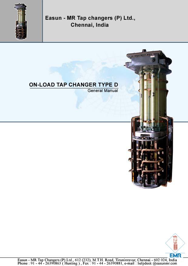
2 CONTENTS 1. Specification Details Description of the On Load Tap Changer Principal Parts of the On Load Tap Changer Diverter Switch Oil Tank Diverter Switch Transition Resistors Tap Selector Delta Tap Changer Electrical Characteristics Electrical Strength Short Circuit Withstand Tap Changing Cycle Motor Drive Drying Out the On Load Tap Changer Inspection Protective Relay
3 1. Specification Details On Load Tap Changer Type D Layout: Applications: Insulation: A.C. test voltage: (50Hz 1,2/50µs) Current rating: Rated Frequency: Short circuit withstand: Step voltage Number of taps: Installed fully sunk in the transformer tank. (Can also be mounted in a separate tank). Diverter switch operates in its own oil space (diverter switch oil tank isolated from the transformer oil. On load tapchanger D III 200, D Ill 400, D Ill 500, as star point tapchanger for three phase transformers and On load tapchanger D Ill 200, D Ill 400 D Ill 500 for application to delta connected transformers or On load tapchanger D 1 400, D I 500, D I 600, D I 800 and D I 1200 as single phase tap changer for single phase transformers or for three phase transformers in any mode of connection. Star point tap changers are used mainly for transmission system transformers and single phase tap changers for auto transformers and industrial transformers supplying furnaces and electrolysis plants. Insulation level voltage to earth 30, (45), 60, (80), 110, 150kV. Tap selector Series 60, 110,150. To earth: according to insulation level voltages to IS, BS, lec, VDE, ASA, etc. Internal selector insulation: withstand voltages for all insulation distance on application. 200, 400, 500 A when star or delta connected 400, 500, 600, 800, 1200 A single phase in any connection Hz Thermal test: 20 times the rated current (rms), duration 3 seconds. Dynamic test: 50 times the rated current (peak value). Particulars of permissible step voltages on application. The values depend on tap selector insulation and circular pitch. Tap selector with preselector (coarse tap selector or reversing switch): ± 8,10,12,14,16 steps with 3 mid position (up to a maximum of 33 working positions differing in voltage). ± 9, 11, 13, 15, 17 steps with one mid position (up to a maximum of 35 working positions differing in voltages). Tap selector without preselector: ± 4 5 6, 7, 8 steps (up to a maximum of 17 working positions differing in voltage). Driving Motor drive as standard equipment can be started and stopped by push buttons from the drive cabinet and also from the control room. Manual operation by crank available if needed. Remote position indication. Versions for parallel operation and for connection to voltage regulators. 3
4 2.Description of the On - Load Tap Changer Fig. 13 shows an on-load tap changer Type D in the form of D III400 three phase unit with an insulation level voltage of 110 kv to earth and a 110 series tap selector for + 13 steps conforming to the design specified in section 1. The principal parts are numbered consecutively and detailed in thelist belonging to Fig.12. The same part numbers are given in brackets throughout the text in the this publication. Models of the on load tap changer type D designed for higher or lower insulation level voltages or tap selector series result in correspondingly larger or smaller vertical dimensions of the diverter switch or tap selector. As in the familar Jansen on load tap changers in the higher range of ratings, which have become firmly established since 1926 the type D on load tap changer likewise retains the same subdivision into a tap selector and a diverter switch giving high speed change over, both units however have been further developed to confer high switching capacity and short circuit withstand and long span,as is described in further details below.the tap selector and diverter switch are mounted as a unit in the transformer tank. Fig. 1 The diverter switch has its own oil tank, whilst the tap selector is immersed in the same oil as the transformer. The tap selector and diverter switch are thus housed in seperate oil chambers. The only fittting projecting above the transformer cover is the tap changer head. This is no higher than the metal bases of the H.T. bushings and thus allows full use to be made of the available space above the transformer head where they are readily accessible. As shown in Fig.2. and 12, the on load tap changer designed on these principles is a unit which hangs from the head (103) and can be bolted either to the transformer cover or to an annexe on the side of the transformer tank after welding on a mounting flange(101). 4
 contains the principal items of the driving mechanism and the position indicators for the diverter switch and tap selector.")
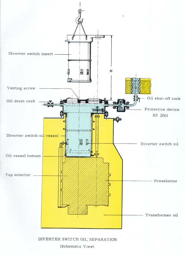
5 When filling the transformer tank with oil,the air which collects inside the mounting flange (101) must be released through a small pipe (102) to atmosphere (valve plug). The on-load tapchanger head (103) contains the principal items of the driving mechanism and the position indicators for the diverter switch and tap selector. The driving mechanism is only visible after removing the cover (106) on the on-load tap changer head whereas the position indicators can be seen through a window (114) even when the cover is in position. The parts mainly concerned are the primary gear unit (121) together with the two Geneva drives (401) giving alternate operation of the two tap selector contact systems (408, 409) and the spring-operated energy accumulator (304) providing a high speed drive to the diverter switch. In addition, there is an important electrical supervisory device, namely the protective relay RS Fig. 2 Load Tap Changer D III 400, 60 kv, Tap Selector Series 110 Directly suspended from the previously mentioned on-load tapchanger head, which in turn bolts to the mounting flange on the transformer cover, is the diverter switch oil tank (203). Screwed to the base (207) of the latter is the tap selector (400) which at one end carries the preselector (500) and which is driven via the tubular driving shafts (402) from the mechanism (121, 401) in the on-load tapchanger head. 3 Principal Parts of the On-Load Tap Changer 3.1 Diverter Switch Oil Tank The diverter switch (300) is housed in its own oiltank (203). The oil in this tank is kept entirely separated from the transformer oil. The oil is, of course, of the same type as that used in the transformer tank, since ordinary transformer oil is perfectly suitable for use as a switch oil. Owing to the contamination brought about in service by arcing, however, the switch oil is kept separate from the transformer oil. It is impossible for the contaminated switch oil, to pass from the diverter switch compartment into the surrounding transformer oil (yellow). The diverter switch oil tank consists of high-grade insulation which in the vertical direction withstands the full working voltage to earth (under earth fault conditions also). Grading rings (208) fitted outside and inside the oil tank (bare up to 45 kv, insulated from 60 kv upwards) promote satisfactory field distribution with a low voltage gradient along the vertical insulation path. Its connection to the conservator ensures that the diverter switch oil tank is kept completely full of oil at all times. 5


6 3.2 Diverter Switch The most important part of the on-load tapchanger is the diverter switch. On the rear cover the diverter switch unit together with the spring-operated energy accumulator is shown withdrawn from the oil tank. Details are shown in Fig. 3 and 4. The main parts of the snap action diverter switch are the transition contacts (323), the transition resistors (315) and the short circuit-proof main contacts (322). The diverter switch has been designed in particular for maximum dependability and freedom from contact bounce. The kinematic principle of the contact system combined with the high speed operation achieved by the spring-operated energy accumulator gives short arcing times which minimize contamination of the switch oil. To extend their working life the diverter switch contacts are faced with a sintered tungsten-copper alloy, for 400 A and 500 A Units. Along with the transition resistors associated with it, the diverter switch is attached to the bottom end of the vertical diverter switch suspension cylinder (307) which is made of fibre reinforced plastic (FRP). At the top end of this cylinder is the diverter switch head (301) with the driving mechanism consisting of the diverter switch drive coupling (303), the spring-operated energy accumulator (304) and the tubular driving shaft (308) (coupling the energy accumulator to the contact system). This has enabled the energy accumulator drive to be accommodated close alongside the main gear unit (121) in the on load tapchanger head (103) where it is accessible at any time for inspection Fig. 3 Diverter Switch Unit, Three basic designs of Diverter switch are available. Diverter Switch Type D 21000: This diverter switch Fig.12 has a current carrying capacity of 200A per phase. This is used in Tap Changers type D III 200, D I500 and D I 600. Diverter Switch Type D 04 66: This diverter switch has a current carrying capacity of 400A per phase. This is used in Tap Changers type DIII 400, D I800 and D I A reinforced design of D is used in tap Changers type D III 500 Fig. 4 Diverter Switch Type

7 Diverter Switch type D 0444: This is basically a single phase switch with a current carrying capacity of 400A and is used in Delta tapchanger of 400 A capacity. As in the case of D 04 66, a reinforced version is available for current carrying capacity of 500A, and this is used in tapchangers type D III 500 Delta. A modified form of D 0444 is used in Delta Switch D III 200 Delta. 3.3 Transition Resistors These are wound with high-grade chrome-nickel alloy wire of circular section and consist of paper laminate panels, the long sides of which are provided with porcelain carriers. Each of the three segments of the diverter switch has four transition resistors making twelve for the diverter switch as a whole. These resistors are mounted as a singe group in an insulated drum and are connected to the diverter switch contacts by screws which cannot work loose. The insulation distances between the individual resistor panels make it necessary for the resistor drum to be filled for the greater part with oil; only a small space is occupied by the active resistance elements. This open type of construction allows very rapid cooling of the resistors which only carry the load during the transition time. The resistors are so designed that there is no need to limit the number of tap changes which can be made in close succession. 3.4 Tap Selector The function of the tap selector is to prepare the tapchange by connecting the diverter switch to the required tap on the transformer (Fig. 6). During this stage the contact system of the diverter switch stays in its original position until the tap selector (Fig. 5) has arrived at the new tap. Thereupon the contact system effects the change-over to bring the new tap into operation. For this purpose the tap selector contacts (407) which connect to the transformer taps are arranged one above the other on the vertical bars of the insulator cage (404). Via these tap selector contacts and rotatable contact bridges (411, 41 0) the necessary inter-connections to suit operating conditions are made between the transformer taps and central take-off rings (411). The latter are connected by conductors (412) and sliding contacts (204) to the contacts (328, 329) of the diverter switch. The current path between the diverter switch and the starpoint output terminal (circular bus-bar 324) includes three further pairs of sliding contacts. The alternate connecting of even-numbered and odd numbered tap selector contacts to the diverter switch contacts takes place on the same switching principles as employed in Jansen switches since as long ago as With this arrangement the tap selector contacts for each phase are divided into two groups odd-numbered contacts 1, 3, 5. and even-numbered contacts 2, 4, 6... which are disposed in two planes on separate cage bars. Two shortcircuit proof contact bridges (411, 410) cooperate with these groups of contacts and are moved alternately from one position to the next in unison with 7
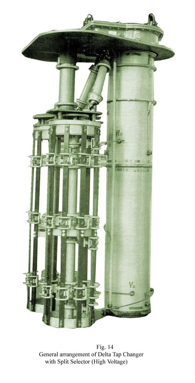
8 the diverter switch action by means of a Geneva mechanism (401). This mechanism is housed in the On load tap changer head (103) where it is readily accessible for checking, and it drives the two contact bridges of the tap selector via a pair of insulated shafts (402) and a reduction gear unit (403) The space-saving layout of the even-numbered and odd-numbered groups of tap selector contacts and the central position of the tap selector conductors (412) from the take-off rings to the conductors at the bottom of the tap selector are features which make for a compact arrangement. The transverse forces brought about by the large number of leads connected to the tap selector are resisted by the metal structure of the selector the central suspension tube of which (413) joins together the upper and lower tap selector cage ring.the tap selector can be built for various numbers of positions. Depending on the circuit arrangement used for connection the regulating winding of the transformer to the tap selector there are types with ± 8,10,12,14 or16 tapping positions, with three mid-positions, and others with ± 9,11,13,15 or 17 tapping positions and only one mid-position. Fig. 6 shows the principal basic circuit arrangements for tap selectors of any circular pitch. The numbers of tapping positions indicated apply to tap selectors with preselector. The on load tapchanger may be provided with a reversing switch or coarse tap selector (502, 504, 506) mounted on the side of the tap selector to keep the interconnecting leads short. The reversing switch gives buck and boost connection of the regulating winding relative to the main winding of the transformer (see Fig. 6 top circuit diagrams), whilst the coarse tap selector connects the regulating winding, either direct or through a coarse tap winding, to the main winding (see Fig. 6, basic circuit diagrams). While the tap selector contact K is in operation, the reversing switch and coarse tap selector are actuated by a driving mechanism (501) running in unison with the motion of the tap selector contact bridge (411) for the odd-numbered contacts. The position of the reversing switch or coarse tap selector can be checked at any time from the position indicator (119) visible through a window (116) in the on-load tapchanger head. Alongside to right and left, the position of the tap selector bridges controlling the odd-numbered and evennumbered contacts can be seen from the numbered dials on the two Geneva units (401). The tap selector and reversing switch or coarse tap selector are immersed in the transformer oil. Insulation distances in the vertical direction are protected against electrical over-stressing by projecting electrodes. In the horizontal direction all insulation paths are through oil. These arrangements give a high standard of protection against surge conditions. 3.5 Delta Tap Changers In the case of tap changers intended for use in Delta connected transformers, it is necessary to provide phase to phase insulation of appropriate value, in both the diverter switch and tap selector. In these cases, three separate diverter switches are necessary, with insulated supports and 8
9 drive shafts between them. If the interphase insulation required is small, it is possible to house the three diverters, which are now axially separated, as also the tap selector in one column, and such delta units look about the same for external appearance as star or single phase units. Where interphase clearance required is high, it may become necessary to mount the diverter switch, and tap selectors in two different columns (See Fig.15) 4 Electrical Characteristics of On-Load Tap Changer 4.1 Electric Strength The electric strength of the insulation to earth corresponds with the stipulated test voltages of the national and international standards systems including IS, BS, VDE, ASA, IEC etc. The withstand voltage to earth of the various insulation paths is higher than, or at least equal to the test values referred to above. The insulation of the on-load tapchanger to earth can be dimensioned independently of the internal insulation of the on-load tapchanger and, in particular, independently of the insulation of the tap selector. The latter is governed by the voltage stressing of the transformer and is graded accordingly in the various sections. The internal electric strength of the tapchanger is determined primarily of the impulse withstand and a.c. withstand voltage of the tap slector. The dimensioning of the tap selector is based in the majority of cases, however on the impulse voltage stressing of the regulating winding. The internal electric strength of the tap selector is provided by allowing appropriate insulation distances in oil and along the selector bars. Through suitable grading of these distances (tap selector contact circle diameter and tap selector length) three different tap selector series have been developed (60, 110 and 150) so that the transformer manufacturer can match the tap selector size to the voltage stressings of the regulating winding arising in service. 9
10 10
11 The standard of insulation quality achieved is confirmed by the excellent results given during years of service by many thousands of on-load tapchangers operating under the most diverse conditions in large transformers upto 220 kv. The transformer manufacturer is responsible for ensuring correct coordination between the electric strength of the on-load tapchanger and the voltage stressing arising in the transformer. 4.2 Short Circuit Withstand The current paths and all contacts in the on-load tapchanger will withstand a thermal short circuit loading at 20 times the rated current for 3 seconds without suffering any damage. They will also withstand dynamic loading up to 50 times the rated current (peak value) without damage. The values specified in the IEC recommendations are thus greatly surpassed. 4.3 Tap Changing Cycle The diverter switch effects the no-break transfer of the current from the tap in service to the tap which has been pre-selected. During the change-over pure ohmic resistance is cut in on the circuit. This gives optimum arc extinction conditions at the critical points in the diverter switch, since the current through the switch is always in phase with the recovery voltage regardless of the power factor (cos) of the transformer load. The change-over action of the diverter switch D is illustrated in the diagram showing a tap change sequence (Fig. 7) and in the oscillogram of a tapchange at the rated load (Fig. 8, 9). The following description outlines the relationship between the various positions of the onload tapchanger and the characteristics of the oscillograms. The diverter switch of the D Ill 200 on load tap changer (200 A rated current) does not have the auxiliary contacts a 2 and b 2 or the associated transition resistors R 2. As will be seen from the above state-by-state description, a tap change involves three circuit-closing and three circuit-opening actions. A tapchange can therefore be divided into three steps. The first step lasts from t 1 to t 2 (positions 2 to 4), the second from t 3 to t 5 (positions 4 to 6) and the third from t 5 to t 7 (positions 6 to 8). Each such step must have a duration of not less than one half cycle of the system frequency. In the example quoted this is the case. 11
12 s Fig.8 Oscillogram of a tap change (single phase) 12
13 Top changer position Oscillogram 1 Main contact at working position A. Transition from 1 to 2 Main contact A opens. Current transfer from main contact A to transition contact a takes place without arc formation, hence not recognizable in oscillogram (current I A ). 2 Auxiliary contact a 2 closes. Transition contact a opens. Starting at time t 1, current l a forms arc, recognizable in oscillogram by occurrence of arc voltage U A. Transition from 2 to 3 current l a flows as arc from t 1, to t 2, extinguished at current zero (t 2 ). UA occurs as arc voltage from t 1, to t 2. 3 U A occurs as recovery voltage from t 2 to t 3 at transition contact voltage drop across R 1 and R 2. 4 Auxiliary contact b 2 closes, recognizable in oscillogram by of commencement of current I b2 (t 3 ). Auxiliary contact a 1 opens, current l a1 occurs as arc starting at t 3. Transition from 4 to 5 Current I a1 occurs as arc at auxiliary contact a 1 from t 3 to t 4, extinguished at current zero (t 4 ). 5 U A occurs as recovery voltage from t 4 to t 5 at auxiliary contact a 1, brought about by voltage drop across R 2 and R 2 connected in parallel. 6 Auxiliary contact b 1 closes, recognizable in oscillogram by commencement of current I b1 (t 5 ). Transition from 6 to 7 Auxiliary contact a 2 opens, current, I a 2 occurs as arc starting at t 5. Current I a2 occurs as arc at auxiliary contact a, from t 5 to t 6, extinguished at current zero (t 6 ). 7 U A occurs as recovery voltage from t 6 to t 7 at auxiliary contact a 2 being equal to the sum of the voltage drop across R 2 and R 1 plus the tap voltage. 8 Transition contact b closes, recognizable in oscillogram by commencement of current l b (t 7 ). Auxiliary contacts b 2 and b 1 shorted by the closing of transition contact b so that no arc occurs on the opening of auxiliary contact b Main contact B closes thereby taking up working position B and passing working current; not recognizable in oscillogram. Tap change completed. 13


14 5. Motor Drive The on load tapchanger type D is operated by a motor drive unit MA2 mounted outside the transformer tank. The motor drive MA2, however, is limited to on load tap changers having not more than 35 tapping positions. All the components which belong to the motor drive are contained in a sheet metal housing designed for outdoor mounting and consisting of a case and a door. The Drive shaft is the mechanical connection between motor drive and tap changer head. The bevel gear serves for diverting motion from the vertical to the horizontal direction. The vertical drive shaft has to be mounted be.tween motor drive and Bevel Gear and the horizontal drive shaft between bevel gear and tap changer. The motor drive unit is powered by a 415V, 50 Hz three phase motor (phase sequence RYB clockwise) and with a stepping mechanism for direct and remote operation. Over travel in either direction is prevented by comprehensive mechanical and electrical safety features. The equipment also includes a six figure counter showing the number of operations performed by the diverter switch, and a dial indicating the present position of the on load tapchanger. Remote indication of on load tapchanger setting at any time can be given by a digital display unit. The built in electric heater prevents condensate forming in the drive housing. For emergency operation and for setting up the motor drive unit when putting the on load tap changer into service, a crank handle is provided. When pushed on to its shaft, this handle interrupts the motor circuit. Re-engagement of the motor drive is brought about by pushing back the locking pin on the shaft after the crank handle has been removed. Fig. 10 Motor Drive MA2 14
15 6 Drying Out the On-Load Tap Changer The undermentioned drying out times should be lengthened accordingly if a fairly long period of storage is unavoidable. Prior to being put on load, the tapchanger must be dried out. The following are the minimum requirements for this process : 6.1 Heat up in air from room temperature to a maximum temperature of 110 o C. The heating must be continued for at least 12 hours and a uniform rate of temperature rise must be ensured (< 10 o /h). 6.2 Drying by air circulation at a maximum temperature of 110 o C for not less than 20 hours. 6.3 Drying for at least 100 hours in vacuum at a residual pressure < 1 mm of mercury without oil, at a maximum temperature of 110 o C. 6.4 Impregnating with prepared oil. The figures stated above represent the minimum drying out times which are necessary in order to maintain or restore the electical properties of the fibre laminate to a satisfactory standard. Over rapid dehumidification under conditions of high vacuum and high temperature is to be avoided, otherwise localized deterioration in the bonding of the material may result. The figures given under 6.1 and 6.2 for the preliminary drying stage should therefore be adhered to strictly. If the on-load tapchanger and transformer have to be dried out simultaneoulsy and if the latter has to be given an extra long period of drying, the final drying stage mentioned under 6.3 above may also be carried out under conditions other than those specified in regard to pressure, temperature and duration, subject to observance of the minimum requirements. Even considerably longer drying times need give rise to no anxiety. On no account, however, should the maximum temperature of 110 o C mentioned earlier be exceeded. To prevent freeze drying the drying out temperature should not be below 60 o C. 7 Inspection In the design and construction of the on load tapchanger special attention has been paid to ensuring that all parts subject to wear in the tapchanger itself and in the motor drive unit, such as the gearing, energy accumulator unit and diverter switch, are readily accessible for checking. as with all switchgear it is advisable that on load tap changers also should be given regular checks at intervals depending on the prevailing duty conditions (see appropriate inspection instructions). After the oil shut-off cock (123) has been closed, the few litres of oil drained off via the oil suction plug (201) and the cover (106) removed, the diverter switch unit can if necessary be withdrawn from the oil tank (203) for checking. This is a simple matter because the connections between the diverter switch and the oil tank are made by sliding contacts (317). After the diverter switch unit has been checked over and overhauled if necessary it goes back into the oil tank again without any possibility of being wrongly positioned. The electrical connections are restored by the sliding contacts already mentioned. At the same time the connection between the main gear unit (121) and the driving crank of the energy accumulator unit (304) is automatically made at a readily visible point in the on-load tapchanger head by means of the coupling (303) (Fig. 12). The tapchanger is now ready for service again. All mechanical movements can be observed with the on-load tapchanger head (103) opened, and the cover (106) need only be refitted after it has been verified that the mechanical functioning of the 15

16 energy accumulator unit together with the latching devices and associated indicating gear is correct. Even with the cover closed, the position indicator is still visible through the window (114). Experience shows that under normal conditions skilled personnel should be able to carry out the necessary inspection on a three-phase on load tapchanger and of the motor-drive operating it in about eight hours. 8 Protective Relay RS 2001 The protective device needed for disconnecting a regulating transformer in which a fault condition has occured includes an oil Surge Operated relay RS 2001 specially developed by us for use with on load tap changers. The protective relay RS2001 (see Fig. 11) reacts to faults in the oil space of the diverter swtich. Under normal load and at the overload permitted for the unit the gases given off do not cause the protective relay to operate. In the event of unduly high pressure surges and in response to a specific rate of oil flow the lever system linked to the flap is operated. Fig. 11. Protective Relay RS
17 2
18 18
19
20
21
22 22
23 23
On-Load Tap changer Type V
 Easun - MR Tap changers (P) Ltd., Chennai, India ON-LOAD TAP CHANGER TYPE V Easun - MR Tap Changers (P) Ltd., 612 (232), M.T.H. Road, Tiruninravur, Chennai - 602 024, India Phone : 91-44 - 26390863 ( Hunting
MOTOR DRIVE UNIT MA General Technical Data Design Control Circuit Assembly... 7
 MOTOR DRIVE UNIT MA 2 Contents Page 1. General... 3 2. Technical Data... 3 3. Design... 4 4. Control Circuit... 7 5. Assembly... 7 6. Putting in to operation... 9 7. Maintenance... 9 8. Special Designs...
SHZV Vacuum On-Load Tap Changer Operation Instructions
 SHZV Vacuum On-Load Tap Changer Operation Instructions HM 0.460.1902 Shanghai Huaming Power Equipment Co.,Ltd. SHZV VACUUM ON-LOAD TAP CHANGER OPERATION INSTRUCTIONS HM0.460.1902 Attentions 1. Please read
SHZV Vacuum On-Load Tap Changer Operation Instructions
 SHZV Vacuum On-Load Tap Changer Operation Instructions HM 0.460.1902 Shanghai Huaming Power Equipment Co.,Ltd. SHZV VACUUM ON-LOAD TAP CHANGER OPERATION INSTRUCTIONS HM0.460.1902 Attentions 1. Please read
On-load tap-changer OILTAP V
 www.reinhausen.com On-load tap-changer OILTAP V Technical Data TD 82/03 Table of Contents Table of Contents 1 General... 4 1.1 Summary of the technical data... 4 1.2 Survey... 6 2 Technical Data... 13
Visual comparison of Plain & Hazy PP Film
 ECOVAR High Voltage Power Capacitors are manufactured at our Sinnar Plant in India which is an ISO 9001 accredited facility & houses a computer aided design manufacturing processing and testing infrastructure
Chapter 6 Generator-Voltage System
 Chapter 6 Generator-Voltage System 6-1. General The generator-voltage system described in this chapter includes the leads and associated equipment between the generator terminals and the low-voltage terminals
Motor-drive mechanism, type BUL. Technical guide
 Motor-drive mechanism, type BUL Technical guide This Technical Guide has been produced to allow transformer manufacturers, and their designers and engineers, access to all the technical information required
5kV to 38kV, 630 Amp to 4000 Amp Indoor or Outdoor Application
 The most advanced Arc-Resistant Switchgear, designed and built to provide maximum safety in the event of an Internal Arcing Fault. 5kV to 38kV, 630 Amp to 4000 Amp Indoor or Outdoor Application Page 1
High-Voltage Circuit-Breakers 3AP1/ kv up to 550 kv. Power Transmission and Distribution
 High-Voltage Circuit-Breakers AP/ 7.5 kv up to 550 kv Power Transmission and Distribution The AP/ High-Voltage Circuit-Breakers Now Applicable for 550 kv Decades of our experience in high-voltage switching
Unified requirements for systems with voltages above 1 kv up to 15 kv
 (1991) (Rev.1 May 2001) (Rev.2 July 2003) (Rev.3 Feb 2015) (Corr.1 June 2018) Unified requirements for systems with voltages above 1 kv up to 15 kv 1. General 1.1 Field of application The following requirements
SION Vacuum Circuit-Breakers. Answers for energy. Medium-Voltage Equipment Selection and Ordering Data. Catalog HG
 Medium-Voltage Equipment Selection and Ordering Data Catalog HG 11.02 2011 Answers for energy. R-HG11-172.tif 2 Siemens HG 11.02 2011 Contents SION Vacuum Circuit-Breakers Medium-Voltage Equipment Catalog
INTRODUCTION. The plug-in connection on the cables and lightning arrestors, allows for easy installation and replacement.
 INTRODUCTION The Power Systems 44 kv MiniSub TM is the most compact system at this voltage available. Utilizing a deadfront termination and lightning arrestor setup, it eliminates the line top or side
Shanghai Huaming Power Equipment Co.,Ltd.
 HM 0.460.4101-03-02/2017 Shanghai Huaming Power Equipment Co.,Ltd. 1 General CV2 on load tap changer (herein referred as the tap changer) is of selector switch structure, which combines the functions
Transformer bushings, type GOH. Technical guide
 Transformer bushings, type GOH Technical guide This Technical Guide has been produced to allow transformer manufacturers, and their designers and engineers, access to all the technical information required
1ZSE en, Rev. 4. On-load tap-changers, type UC User s manual
 1ZSE 5492-155 en, Rev. 4 On-load tap-changers, type UC User s manual Original instruction The information provided in this document is intended to be general and does not cover all possible applications.
Instruction manual. EK6 Earthing switch 36/40.5 kv
 Instruction manual EK6 Earthing switch 36/40.5 kv Your safety first always! That s why our instruction manual begins with these recommendations: Only install switchgear and/or switchboards in enclosed
SF6 GAS INSULATED METAL ENCLOSED SWITCHGEAR (GIS)
") SF6 GAS INSULATED METAL ENCLOSED SWITCHGEAR (GIS) About company The «Elektroapparat» plant starts its operation in 1922 as a plant manufacturing high-voltage electrical equipment. During the first two
SF6 GAS INSULATED METAL ENCLOSED SWITCHGEAR (GIS) About company The «Elektroapparat» plant starts its operation in 1922 as a plant manufacturing high-voltage electrical equipment. During the first two
Voltage Rated operating voltage [kv] Rated power frequency withstand voltage [kv] Rated lightning impulse withstand voltage [kv]
![Voltage Rated operating voltage [kv] Rated power frequency withstand voltage [kv] Rated lightning impulse withstand voltage [kv]](/thumbs/80/82203973.jpg "Voltage Rated operating voltage [kv] Rated power frequency withstand voltage [kv] Rated lightning impulse withstand voltage [kv]") BasisBlock MC 1 Standards and Regulations IEC 62271-200 ; VDE 0671-200 ; BS EN 62271-200 Technical Data MC1-12 MC1-24 Voltage Rated operating voltage [kv] 12 24 Rated power frequency withstand voltage
BasisBlock MC 1 Standards and Regulations IEC 62271-200 ; VDE 0671-200 ; BS EN 62271-200 Technical Data MC1-12 MC1-24 Voltage Rated operating voltage [kv] 12 24 Rated power frequency withstand voltage
Horizontal Circuit Switchers
 > Transformer Protection > CIRCUIT SWITCHERS C A T A L O G B U L L E T I N General Application Southern States Types CSH and CSH-B Horizontal Circuit Switchers provide an economical, versatile, space saving
ME Switchgear with Vacuum Circuit Breaker and Auto-jet II Switch with Ground Position
 LET S BE PACIFIC November 0 Volume Number 5 ME Switchgear with Vacuum Circuit Breaker and Auto-jet II Switch with Ground Position Federal Pacific has the capability to engineer, fabricate and assemble
Technical information
 Technical information General Regulations WTL current transformers are special transformers which transfer the primary circuits with prescribed accuracy in smaller secondary circuits. Primary and secondary
On-load tap-changers, types UCG, UCL, UCC and UCD with motor-drive mechanisms, types BUE and BUL Spare Parts List
 On-load tap-changers, types UCG, UCL, UCC and UCD with motor-drive mechanisms, types BUE and BUL Spare Parts List ZSE 5492-33 en, Rev. 3, 2004-04-5 This document must not be copied without our written
FUSES. Safety through quality
 Safety through quality HH HIGH VOLTAGE Over many decades SIBA has developed a global product line of High Voltage Fuses that are comprehensive for any and all applications. Superior engineering, advanced
SF 6 Gas Insulated Switchgear Type SDH314 / SDHa314 for 72.5 to 145 kv
 Three Phase Encapsulated Type SF 6 Gas Insulated Switchgear Type SDH314 / SDHa314 for 72.5 to 145 kv 06B1-E-0002 Small Space Requirement, High Reliability and Safety ー 72.5 to 145 kv GIS, SDH314/SDHa314
Voltage limiting device HVL
 Datasheet Voltage limiting device HVL 60-0.3 1 2 3 3 Equivalent circuit of voltage limiting device Type HVL 60-0.3 1 MO-surge arrester 2 Trigger electronics 3 Thyristor Product Description The HVL 60-0.3
Voltage limiting device HVL
 Datasheet Voltage limiting device HVL 120-0.3 1 2 3 3 Equivalent circuit of voltage limiting device Type HVL 120-0.3 1 MO-surge arrester 2 Trigger electronics 3 Thyristor Product Description The HVL 120-0.3
INSTRUCTION MANUAL RELAY FOR ON LOAD TAP CHANGER APPLICATIONS OR-25 5COR OR25 REV03
 INSTRUCTION MANUAL RELAY FOR ON LOAD TAP CHANGER APPLICATIONS OR-25 5COR469000 OR25 REV03 I II CONTENT: 1 SAFETY 1.1 Safety instructions 2 1.2 Specified applications 2 1.3 Safety notes on the equipment
Outdoor live tank SF 6. circuit breaker Type OHB for 24/36/40.5 kv applications
 Outdoor live tank SF 6 circuit breaker Type OHB for 24/36/40.5 kv applications ABB a global leader ABB is a global leader in Power and Automation technologies that enable utility and industry customers
Vacuum Circuit-Breakers, Type HVX kv, of cassette design, cassette with motor drive
 Vacuum Circuit-Breakers, Type HVX 12 24 kv, of cassette design, cassette with motor drive Operating Instructions No. 531 321, Edition 09/00 Table of Contents 1 General 4 1.1 Operating Conditions 4 2 Design,
Outdoor vacuum breaker for railway applications - FSK II
 Outdoor vacuum breaker for railway applications - FSK II Single or two-pole outdoor vacuum breaker with magnetic actuator 27.5 kv - 250 kv BIL - 1250 A. 2000 A - 25.0 ka - 50/60 Hz 27.5 kv - 200 kv BIL
HHD HIGH VOLTAGE FUSES GERMAN DIN STANDARD. The temperature limiting function of the fuse striker pin. Design and construction.
 HHD HIGH VOLTAGE GERMAN DIN STANDARD FOR AIR & GAS INSULATED SWITCHGEARS OUTDOOR SWITCHGEARS The striker pin system is connected by means of a high resistance parallel conductor. After melting the main
1ZSC AAA EN, REV. 7. Transformer bushings type GSBK Technical guide
 1ZSC563-AAA EN, REV. 7 Transformer bushings type GSBK Technical guide Original instruction The information provided in this document is intended to be general and does not cover all possible applications.
MAHALAKSHMI ENGINEERING COLLEGE TIRUCHIRAPALLI
 MAHALAKSHMI ENGINEERING COLLEGE TIRUCHIRAPALLI 621213 QUESTION BANK --------------------------------------------------------------------------------------------------------------- Sub. Code : EE2402 Semester
SWITCHGEAR. 4G cam switches
 SWITCHGEAR 178 4G cam switches ENERGY SAFELY SWITCHED 179 SWITCHGEAR 180 GENERAL INFORMATION 4G-series cam switches are low voltage switches, designed according to the latest knowledge about switchgear
TRANSFORMERS UP TO 750 kv
 Electric Co. Ltd. TRANSFORMERS UP TO 750 kv CONTENTS General... 2 Products... 3 Construction...4 Magnetic core... 4 Windings...5 Frame structure... 6 Connections...6 Tap changer and motor drive...7 Tank...
INSTRUCTION MANUAL BR 25 FOR RAILWAY APPLICATION 5COR BR25AT REV00
 INSTRUCTION MANUAL BR 25 FOR RAILWAY APPLICATION 5COR469100 BR25AT REV00 I CONTENT: 1 SAFETY 1.1 Safety instructions 1 1.2 Specified applications 1 1.3 Safety notes on the equipment operation 1 2 BR 25
with Vacuum Circuit Breaker HAF
 M E T A L - C L A D S W I T C H G E A R Safety and Reliability with Vacuum Circuit Breaker HAF Flexible Design and Compact with Vacuum Circuit Breaker HVF Easy Installation and Maintenance We build a better
On-Load Tap-Changer Type CM Operating Instructions
 HM0.60.30 On-Load Tap-Changer Type CM Operating Instructions HM 0.60.30-03.0/205 Shanghai Huaming Power Equipment Co., Ltd. 2 HM0.60.30 Thank you for choosing on-load tap-changer Prior to using the on-load
Teepak Totally Enclosed Tube Ventilated High Voltage Induction Motors. A Regal Brand.
 Teepak Totally Enclosed Tube Ventilated High Voltage Induction Motors A Regal Brand www.regalbeloit.com Specifications Range Poles Voltage : Upto 3000 KW : Upto 14 Pole : Upto 11000 Volt Frame : 450 1000
DISTRIBUTION SOLUTIONS. GSec Gas-insulated switching and isolating apparatus
 DISTRIBUTION SOLUTIONS GSec Gas-insulated switching and isolating apparatus GSec is a three-position SF6 gas-insulated switchdisconnector designed for use in medium voltage switchgear for secondary distribution
Ultra-Rapid Fuse Links for the Protection of Semiconductor Rectifiers
 Ultra-Rapid Fuse Links for the Protection of Semiconductor Rectifiers 1.General The design of rectifier equipment requires specific provisions in the switchgear for the protection of power semiconductor
MINIATURE CIRCUIT BREAKER
 Technical Article MINIATURE CIRCUIT BREAKER T 146 PURCHASE he Spaceage MCB protects wires and cables automatically against overload and short-circuits in domestic, commercial and industrial installations.
B kv Gas-insulated Substations
 72.5 145 kv Gas-insulated Substations The increasing demand for electrical power in cities and industrial centres requires the installation of a compact and efficient distribution and transmission network.
SION Vacuum Circuit-Breakers. Answers for energy. Medium-Voltage Equipment Selection and Ordering Data. Catalog HG
 Medium-Voltage Equipment Selection and Ordering Data Catalog HG 11.0 008 Answers for energy. R-HG11-17.tif Siemens HG 11.0 008 Contents Contents Page SION Vacuum Circuit-Breakers Description General Construction
Resin Impregnated Paper Bushing, Oil to SF 6. , Type GSBK
 1ZSC563-AAA en, Rev. 2 Resin Impregnated Paper Bushing, Oil to SF 6, Type GSBK Technical guide This Technical Guide has been produced to allow transformer manufacturers, and their designers and engineers,
Horizontal Circuit Switchers
 > Transformer Protection > CIRCUIT SWITCHERS C A T A L O G B U L L E T I N General Application Southern States Types CSH and CSH-B Horizontal Circuit Switchers provide an economical, versatile, space saving
CONTENT. EPE METALCLAD SWITCHGEARS AMS SERIES 12kV AMS METALCLAD SWITCHGEAR 24kV AMS METALCLAD SWITCHGEAR 40.5KV AMS METALCLAD SWITCHGEAR
 CONTENT EPE METLCLD SWITCHGERS SERIES EPE 1220 / - 12KV METLCLD SWITCHGER EPE 10D - 12KV METLCLD SWITCHGER EPE 24-24KV METLCLD SWITCHGER EPE 36-36KV METLCLD SWITCHGER EPE METLCLD SWITCHGERS MS SERIES 12
Power & High Voltage Joslyn Hi-Voltage Overhead Reclosers & Switches H-220. Series HVI Hi-Velocity Interrupter Attachment
 Use load interrupter attachments to enable loop sectionalizing, line dropping, load breaking and transformer-magnetizing current interruption. Increase the capability of your disconnect switches by adding
TECHNICAL INFORMATION. Dipl.-Ing. (FH) Christian Niklis. Stationary Lance Earthing Device
 Christian Niklis. Stationary Lance Earthing Device") TECHNICAL INFORMATION Dipl.-Ing. (FH) Christian Niklis Stationary Lance Earthing Device GENERAL Lance earthing devices - What s s the use of them? Short-circuit-proof earthing in high voltage substations
TECHNICAL INFORMATION Dipl.-Ing. (FH) Christian Niklis Stationary Lance Earthing Device GENERAL Lance earthing devices - What s s the use of them? Short-circuit-proof earthing in high voltage substations
Medium voltage switchgear type W 12. rated voltage 12 kv rated current 630 A
 Medium voltage switchgear type W rated voltage kv rated current 0 A General The metal-encapsulated, air-insulated medium voltage switchgears, type W are for universal application. They range from compact
UBC Technical Guidelines Section Edition Commissioning of Electrical Systems Page 1 of 5
 Page 1 of 5 1.0 GENERAL 1.1 Coordination Requirements.1 UBC Building Operations Electrical Technical Support.2 UBC Energy & Water Services 2.0 REQUIREMENTS FOR COMMISSIONING AND TESTING 2.1 Testing.1 Unit
IEC Standard Compliant Vacuum Circuit-Breaker (12 kv, 24 kv) for Southeast Asian Markets
 for Southeast Asian Markets") IEC Standard Compliant Vacuum Circuit-Breaker (12 kv, 24 kv) for Southeast Asian Markets OKAZAKI, Takayuki KIKUCHI, Masanori TOKUNAGA, Yoshihide A B S T R A C T As Southeast Asia continues to experience
IEC Standard Compliant Vacuum Circuit-Breaker (12 kv, 24 kv) for Southeast Asian Markets OKAZAKI, Takayuki KIKUCHI, Masanori TOKUNAGA, Yoshihide A B S T R A C T As Southeast Asia continues to experience
B kv T&D GAS INSULATED SWITCHGEAR
 GAS INSULATED SWITCHGEAR B 105 170 300 kv The increasing demand for electrical power in cities and industrial centers necessitates the installation of a compact and efficient distribution and transmission
MEDIUM VOLTAGE PRODUCTS. Fault Current Limiters I S. -limiter and FC-Protector The worldʼs fastest switching devices
 MEDIUM VOLTAGE PRODUCTS The worldʼs fastest switching devices 2 FAULT CURRENT LIMITERS THE WORLDʼ S FASTETST SWITCHING DEVICES The worldʼs fastest switching devices ABBʼs fault current limiters disconnect
Generator Termination Bus-bar Arrangement - Design requirements: Utility Perspective
 Generator Termination Bus-bar Arrangement - Design requirements: Utility Perspective D. K. Chaturvedi (NTPC) Harshvardhan Senghani (NTPC) K Venugopal (CS Electric) This paper appraise user on the termination
IEC Low Voltage General Purpose Protection
 , 6A, 0/400VAC (/440VAC) Complying with DIN VDE 0660 Part 07 EN / IEC 60947- DIN VDE 066 Part IEC 6069- DIN VDE 068 DIN VDE 4880 The D0-LINOCUR is a combination of switch-disconnector-fuse and NEOZED 6
Product presentation CPT tech Jason Evershed, ABB Transformer Components, May 21st Dry-type transformers Innovative Technology
 Product presentation CPT tech Jason Evershed, ABB Transformer Components, May 21st 2014 Dry-type transformers Innovative Technology What is a dry transformer? ABB manufactures a transformer which does
1ZSE EN, REV. 7. Oil SF 6. bushings type GOEK Technical guide
 1ZSE 2750-106 EN, REV. 7 Oil SF 6 bushings type GOEK Technical guide Original instruction The information provided in this document is intended to be general and does not cover all possible applications.
Safe, fast HV circuit breaker testing with DualGround technology
 Safe, fast HV circuit breaker testing with DualGround technology Substation personnel safety From the earliest days of circuit breaker testing, safety of personnel has been the highest priority. The best
(Under Two Part Bid System) Tender No: NFV/ PUR/ BEC K for VCB
 Tender No: NFV/ PUR/ BEC K for VCB") Annexure-V (Under Two Part Bid System) Tender No: NFV/ PUR/ BEC 160546 K for VCB Technical specification for NIT SL NO 1 S.No. Description NFL requirement as per NIT Vendors Comment [Agreed / If not agreed,
Annexure-V (Under Two Part Bid System) Tender No: NFV/ PUR/ BEC 160546 K for VCB Technical specification for NIT SL NO 1 S.No. Description NFL requirement as per NIT Vendors Comment [Agreed / If not agreed,
THP145 HYBRID GAS INSULATED SWITCHGEAR (HGIS) Energy, Fast! tgood.com
 Energy, Fast! tgood.com") THP145 HYBRID GAS INSULATED SWITCHGEAR (HGIS) Energy, Fast! tgood.com TGOOD produces over 5000 switchgear units annually for projects around the globe SOLUTION OVERVIEW For use in affordable air insulated
THP145 HYBRID GAS INSULATED SWITCHGEAR (HGIS) Energy, Fast! tgood.com TGOOD produces over 5000 switchgear units annually for projects around the globe SOLUTION OVERVIEW For use in affordable air insulated
EISHO TEK. Vacuum Circuit Breaker
 EISHO TEK Vacuum Circuit Breaker TYPE:SV1-12 INSTRUCTION MANUAL Operation and Maintenance Version TAIWAN CALSONIC SAFETY PRECAUTIONS For safety reason, this equipment should be handled by personnel who
The University of New South Wales. School of Electrical Engineering and Telecommunications. Industrial and Commercial Power Systems Topic 2
 The University of New South Wales School of Electrical Engineering and Telecommunications Industrial and Commercial Power Systems Topic 2 SWITCHBOARDS Overview Also called Switchgear and Controlgear Assembly
Maximum temp. rise in oil by 40 thermometer above design ambient (deg C) specified time Short circuit rating (Sec) for As per IS 2026
 specified time Short circuit rating (Sec) for As per IS 2026") TECHNICAL PERTICULAR FOR 1.6 MVA 6.6/0.433 KV SERVICE TRANSFORMER 1.00.00 GENERAL 1.01.00 Service SERVICE 1.02.00 Make ASHOK/VOLTAMP/DANKE/CGL 1.03.00 Type CORE 1.04.00 Location OUTDOOR 1.05.00 Specification
TECHNICAL PERTICULAR FOR 1.6 MVA 6.6/0.433 KV SERVICE TRANSFORMER 1.00.00 GENERAL 1.01.00 Service SERVICE 1.02.00 Make ASHOK/VOLTAMP/DANKE/CGL 1.03.00 Type CORE 1.04.00 Location OUTDOOR 1.05.00 Specification
017: 1998 CEB STANDARD RING MAIN UNIT CEYLON ELECTRICITY BOARD SRI LANKA
 017: 1998 CEB STANDARD RING MAIN UNIT CEYLON ELECTRICITY BOARD SRI LANKA CONTENTS PAGE 1. Scope 2 2. System Parameters 2 3. Service Conditions 2 4. Applicable Standards 3 5. Basic Features 4 6. Quality
DEPARTMENT OF ELECTRICAL ENGINEERING DIT UNIVERSITY HIGH VOLTAGE ENGINEERING
 1 DEPARTMENT OF ELECTRICAL ENGINEERING Introduction to High Voltage Testing It is essential to ensure that the electrical equipment is capable of withstanding the overvoltages that are met within the service.
DIN HV Distribution. DIN HV fuses are partial-range high voltage currentlimiting fuses for use in distribution circuits from kV.
 DIN HV Distribution DIN HV fuses are partial-range high voltage currentlimiting fuses for use in distribution circuits from 2.3-38kV. Their compact dimensions and non-venting characteristics make them
Introduction to Circuit Breaker. Working Principle of Circuit Breaker
 Definition of Circuit Breaker : - Electrical Circuit Breaker is a switching device which can be operated manually as well as automatically for controlling and protection of electrical power system respectively.
1ZSC AAA en, Rev. 6. Resin impregnated paper bushing, oil to SF 6., type GSBK Technical guide
 1ZSC563-AAA en, Rev. 6 Resin impregnated paper bushing, oil to SF 6, type GSBK Technical guide Original instruction The information provided in this document is intended to be general and does not cover
Medium-voltage fuses 3 kv 40.5 kv, 0.4 A 315 A
 DISTRIBUTION SOLUTIONS Medium-voltage fuses 3 kv 40.5 kv, 0.4 A 315 A Continuous protection and reliable operation Proven design and compliance with newest fuses standards Compatibility with other ABB
Drive Duty Transformer Specification Virginia Transformer Corp. Power Up! Selecting the Right Transformer
 Drive Duty Transformer Specification Virginia Transformer Corp. Power Up! Selecting the Right Transformer This document contains sample specifications for Liquid-Filled Type Drive Transformers You may
Publication No.: PSG
 TABLE OF CONTENTS PAGE 1.0 SCOPE...2 2.0 STANDARDS...2 3.0 DESIGN REQUIREMENTS...2 3.01 Service Conditions... 2 3.02 Ratings... 3 3.03 Resistors... 3 3.04 Interrupter... 4 3.05 SF 6 Gas System... 4 3.06
Pantograph disconnector type GW54, up to 550 kv Maximum reliability and minimal maintenance
 Pantograph disconnector type GW54, up to 550 kv Maximum reliability and minimal maintenance Table of contents 02 03 04 05 06 07 08 Disconnectors from ABB Maximum reliability and minimal maintenance Technical
Vane pumps, direct controlled Type PV7...A
 Vane pumps, direct controlled Type PV7...A Nominal sizes 1 to 25 eries 1X Maximum operating pressure 1 bar Displacements from 1 to 25 cm 3 H/A 617/95 Type PV7-1X/..RA1MA-... H/A/D 56/97 Typ MPU1-V71-9L/...
SF 6 Gas Insulated Switchgear Type SDH714 for 72.5 to 145 kv
 Three-phase Encapsulated Type SF 6 Gas Insulated Switchgear Type SDH714 for 72.5 to 145 kv 06B1-E-0020 Small Space Requirement, High Reliability and Safety ー 72.5 to 145kV GIS, SDH714 The number of application
1ZSE EN, REV. 4. Wall bushings type GSA-AA Technical guide
 1ZSE 2750-112 EN, REV. 4 Wall bushings type GSA-AA Technical guide Original instruction The information provided in this document is intended to be general and does not cover all possible applications.
Design considerations for generator set mounted paralleling breakers
 Our energy working for you. Design considerations for generator set mounted paralleling breakers White Paper Hassan Obeid, Application Group Cummins Power Generation Cummins Power Systems has been delivering
Boric Acid Fuse Links
 Boric Acid Fuse Links BBU Fuse Link Mount Construction Bird proof design insulator provides insulation characteristics higher than ANSI distribution cut-out standards and equal in most cases to ANSI switch
Oil Circuit Breakers
 ČESKÉ VYSOKÉ UČENÍ TECHNICKÉ V PRAZE Fakulta elektrotechnická Katedra elektrických pohonů a trakce K13114 BE1M 14 ESP Electrical apparatuses and machines Oil Circuit Breakers BE1M14 SSP Electrical apparatuses
AF series contactors (9 2650)
") R E32527 R E39322 contactors General purpose and motor applications AF series contactors (9 2650) 3- & 4-pole contactors General purpose up to 2700 A Motor applications up to 50 hp, 900 kw NEMA Sizes 00
R E32527 R E39322 contactors General purpose and motor applications AF series contactors (9 2650) 3- & 4-pole contactors General purpose up to 2700 A Motor applications up to 50 hp, 900 kw NEMA Sizes 00
Air-insulated switchgear UniGear type ZS1
 Air-insulated switchgear UniGear type ZS1 ABB Power Technologies / 1-7074 D 12-03-2003 - Air-insulated switchgear UniGear type ZS1 ABB Power Technologies / 2-7075 D 1 2-03-2003 - Rated voltage kv 12 17.5
KYN28A-12 (GZS1) A.C METALCLAD REMOVABLE SWITCHGEAR FOR INDOOR USE CHINATCS
 A.C METALCLAD REMOVABLE SWITCHGEAR FOR INDOOR USE CHINATCS") KYN28A-12 (GZS1) A.C METALCLAD REMOVABLE SWITCHGEAR FOR INDOOR USE CHINATCS 2001.09 KYN28A-12 (GZS1) A.C Metalclad Removable Switchgear for Indoor Use --------The Leader in Switchgear Up to 12kV 1. The
KYN28A-12 (GZS1) A.C METALCLAD REMOVABLE SWITCHGEAR FOR INDOOR USE CHINATCS 2001.09 KYN28A-12 (GZS1) A.C Metalclad Removable Switchgear for Indoor Use --------The Leader in Switchgear Up to 12kV 1. The
A system fault contribution of 750 mva shall be used when determining the required interrupting rating for unit substation equipment.
 General Unit substations shall be 500 kva minimum, 1500 kva maximum unless approved otherwise by the University. For the required configuration of University substations see Standard Electrical Detail
Outdoor disconnectors FTr (previously 6400 and 6410) single- and three-pole design rated voltage 25 and 38.5 kv rated current 400 and 630 A
 single- and three-pole design rated voltage 25 and 38.5 kv rated current 400 and 630 A") Outdoor disconnectors FTr (previously 6 and 6410) single- and three-pole design rated voltage 25 and 38.5 kv rated current and 6 A 1 Outdoor disconnectors Outdoor disconnectors, produced in accordance
Outdoor disconnectors FTr (previously 6 and 6410) single- and three-pole design rated voltage 25 and 38.5 kv rated current and 6 A 1 Outdoor disconnectors Outdoor disconnectors, produced in accordance
HHD. High Voltage Fuses German DIN Standard. The temperature limiting function of the fuse striker pin. Design and construction.
 HHD High Voltage Fuses German DIN Standard For Air & Gas Insulated Switchgear Indoor and Outdoor Application The striker pin system is connected by means of a high resistance parallel conductor. After
1ZSE en, Rev. 3. Wall bushings, type GSA-AA Technical guide
 1ZSE 2750-112 en, Rev. 3 Wall bushings, type GSA-AA Technical guide Original instruction The information provided in this document is intended to be general and does not cover all possible applications.
Earthing Switch Class B Hochspannungstechnik Peters & Thieding GmbH
 Peters& Thieding Hochspannungstechnik GmbH Earthing Switch Class B Hochspannungstechnik Peters & Thieding GmbH OVERVIEW The PTE earthing switch is an indoor switching device for installation in air-insulated
www. ElectricalPartManuals. com INSTRUCTIONS "INERTEEN AND OIL INSULATED FEEDER SWITCHES DESCRIPTION INSTALLATION MAINTENANCE
 r \ FIG. 1. Cutaway View of Typical Switch. I.L. 46-723-1 DESCRIPTION INSTALLATION MAINTENANCE INSTRUCTIONS THE INERTEEN AND OIL INSULATED FEEDER SWITCH provides complete switching facilities in a minimum
1ZVN A. Application manual
 1ZVN460100 A Application manual 1ZVN460100 A 2 / 3 Table of contents 1 Rating Plate... 2 Tapchanger... 3 Bushing... 4 Cooling Equiptment... 5 Current Transformer... 6 Other Acessories... 7 Drawings...
AF series contactors (9 2650)
") R E32527 R E39322 contactors General purpose and motor applications AF series contactors (9 2650) 3- & 4-pole contactors General purpose up to 2700 A Motor applications up to 50 hp, 900 kw NEMA Sizes 00
R E32527 R E39322 contactors General purpose and motor applications AF series contactors (9 2650) 3- & 4-pole contactors General purpose up to 2700 A Motor applications up to 50 hp, 900 kw NEMA Sizes 00
Product Specifications for Aluminum Vertical Break Switches
 1. General a) This specification covers the design, manufacture, and shipment of aluminum vertical break switches, both air-break and load-break configurations, for substation and transmission switching
PHOENIX CONTACT
 Current transformers INTERFACE Data sheet 03359_en_03 PHOENIX CONTACT 20-04-04 Description The PACT Analog current transformers form a complete range of bus-bar, plug-in and winding current transformers
Our brand POWER DYNAMIC PASSION COMMITMENT CREATIVITY. A strong brand for strong products: 8PU Premium. MV Energy
 Our brand A strong brand for strong products: The ENERGOLINE brand represents our product portfolio of INDUSTRIAL SWITCHGEAR SYSTEMS. Our products are characterized by a high degree of safety, flexibility
Introduction. Kinematics and Dynamics of Machines. Involute profile. 7. Gears
 Introduction The kinematic function of gears is to transfer rotational motion from one shaft to another Kinematics and Dynamics of Machines 7. Gears Since these shafts may be parallel, perpendicular, or
Unit Protection System for Pumped-Storage Power Stations
 Unit Protection System for Pumped-Storage Power Stations 1. Introduction In many power systems, pumped-storage power stations are used in addition to run-of-river power stations. These power stations serve
Extensible Unit - VCE2a
 ELECTRICAL INDUSTRIAL COMPANY (EICo) LUCY SWITCHGEAR Extensible Unit - VCE2a (Sabre) Electrical Industrial Company (EICo) Lucy Switchgear Extensible Unit VCE2a Front Panel: ELECTRICAL INDUSTRIAL COMPANY
Essential Loads also use stand by generator systems mostly in process industries as they relate to high restarting times or high down times.
 The need for continuous power supply and its reliability has increased rapidly over the years, especially in all those areas where uninterrupted power supply is a must. Modern systems are power dependent.
www. ElectricalPartManuals. com CPL Station Arrester Controlled Protective Level Page 1 Indoor-Outdoor Altitude 0-10,000 feet KV
 December, 1975 New nformation and Supersedes DB 38-131 Pages 1-4, dated May 1972, and 38-121 D WE A, Pages 1-4, dated April1974 E, D, C/1981/ DB Westinghouse Electric Corporation Distribution Apparatus
1ZSE en, Rev. 7. Transformer bushings, type GOB Technical guide
 1ZSE 2750-102 en, Rev. 7 Transformer bushings, type GOB Technical guide This Technical Guide has been produced to allow transformer manufacturers, and their designers and engineers, access to all the technical