Geothermal Pipe Bending
|
|
|
- Rudolf Fitzgerald
- 6 years ago
- Views:
Transcription

1 Geothermal Pipe Bending Marshall Oldham Ryan Turner Sarah Reiss 2012 Fall Design Report Prepared for Charles Machine Works, Inc.
2 Table of Contents 1. Mission Statement 3 2. Introduction to Problem 3 3. Problem Statement 4 4. Statement of Work a. Statement of Work 4 b. Location of Work 4 c. Period of Performance 5 d. Gantt Charts 5 e. Deliverable Requirements 5 f. Work Breakdown Structure 5 g. Task List 5 5. Market Research 6 6. Technical Analysis a. Customer Limitations 7 b. Testing 7 c. Material Limitations 9 d. Similar Designs 9 e. Patent Searches Design Concepts a. Generation of Design Concepts 10 i. Design I 10 ii. Design II 13 iii. Calculations 14 iv. Drive Systems 17 v. Banding 17 b. Safety Design Evaluation a. Feasibility Evaluation of Possible Designs Project Budget Appendices 24 2 P a g e
3 MISSION STATEMENT D.T.E. is dedicated to coming up with creative and innovative designs with our client s satisfaction as our top priority. We are devoted to designing solutions that are cost efficient, reliable, and exceed all expectations. We promise to put our client s needs first through the entirety of the project. Our innovation can make your engineering dreams come to life. INTRODUCTION TO PROBLEM Ditch Witch has always been a leader and innovator of underground construction equipment. In recent years geothermal heat pump installation has become a large industry and many companies use Ditch Witch trenchless equipment for digging wells. Current methods for geothermal installation involve a large hole and multiple small loops sent down hole. The loops are secured with grout in the hole. One of the biggest problems in the process is adding the grout down hole to secure the pipe. Not only is it costly, but also reduces the efficiency of the geothermal system. Ditch Witch has set out to improve the installation process by reducing the amount of grout needed. To reduce the amount of needed grout, Ditch Witch has requested that D.T.E. design a prototype machine that can reduce the outer diameter of the pipe temporarily. By doing this a smaller diameter hole can be dug in the ground. This smaller hole will allow the pipe to create a tight fit once down hole and expanded back to its original shape. This will reduce the amount of grout needed to secure the pipe and also increase heat transfer efficiency. 3 P a g e
4 PROBLEM STATEMENT Charles Machine Works, Inc. has assigned the task of evaluating the feasibility of bending 4.5 inch outer diameter High Density Polyethylene (HDPE) pipe into a U shape cross sectional area reducing the outer diameter when folded. If bending the HDPE pipe into said shape is feasible, then D.T.E. will design and build a machine that can achieve this profile for the pipe. STATEMENT OF WORK a. SOW DTE will design and develop a machine to address the problem statement. This machine will crease HDPE pipe, incorporate a 1 inch grout line into the U cross section and a banding mechanism to maintain the U shape with the inserted grout line until the pipe is inserted down hole. The purpose of bending the pipe is to reduce the outer diameter. This will allow for a smaller drill hole, tighter fit, and less cement to secure the pipe. b. Location of Work The work will take place at several locations. The prototype dies for testing the pipe will be assembled in the BAE lab. The testing will take place in the BAE lab also, using the BAE Instron Machine. The dies will be made at Ditch Witch. Ditch Witch has offered to make any pieces of our design that cannot be made at the BAE lab. 4 P a g e
5 c. Period of Performance The project will start in August 2012 and will be completed at the beginning of May d. Gantt Chart A Gantt Chart is used to outline what will take place during the completion of the project. This chart can be found in Appendix 1. e. Deliverable Requirements Ditch Witch has requested we build a machine to fold, band, and package HDPE pipe with the following specifications. The machine will be made to handle HDPE SDR 21 pipe with an outer diameter of 4.5 inches. The machine will need to handle 300 feet of pipe in a 30 minute time period. The pipe needs to be bent and banded into a U shape cross section with a 1 inch grout line in the center. The banding mechanism must be able to be broken once the pipe is inserted down hole; therefore the banding mechanism must break at 100 PSI. The machine should only take 1 person to properly and safely operate. All drive systems need to be powered by hydraulics. f. Work Breakdown Structure The work breakdown structure is a tabular representation of the tasks necessary to complete the project. The full work breakdown structure is located in Appendix II. g. Task List 1.0 -Testing 1.1 Create test dies to test the pipe in the Instron machine 1.2 Test the pipe 1.3 Gather data and analyze to determine whether the dies are feasible 1.4 Analyze the forces observed by the frame 5 P a g e
6 1.5 Test the amount of force required to push pipe 1.6 Develop a drive train to apply the required force to the pipe 1.7 Test pipe for forces required to keep in U-Shape 1.8 Design band to apply forces to keep the pipe in the U-Shape Pipe Bending Machine 2.1 Dies for bending pipe 2.2 Die driving mechanism 2.3 Design Frame 2.4 Drive mechanism 2.5 Grout line insert mechanism 2.6 Bands for holding the pip in U Shape 2.7 Banding mechanism 2.8 Mechanism for putting bent and banded pipe on reel Documentation 3.1 Drafting 3.2 Write design report 3.3 Gantt charts and MS Project 3.4 Solid Works drawings Engineering Review and Approval 4.1 Review and approve engineering 4.2 Review, approve, and finalize drawings Fabricate and Procure System Materials 5.1 Procure Materials 5.2 Fabricate frame and full assembly Integration of system 6.1 Deliver to Charles Machine Works 6.2 Functional checks MARKET RESEARCH CMW doesn t have any market competition in the development of this machine. This is strictly a research and design task to check the feasibility of bending the HDPE pipe into a U shape. Further testing will have to be done with the pipe down hole to determine if the system will be improved over current methods. Once the method is proven, CMW will have to decide whether they want to sell the machine or the bent pipe. This will determine what 6 P a g e
7 portion of the market they will be in. economic analysis was done by OSU Ag Econ group consisting of Justin Anderson and Alan Smith. Their analysis can be found in Appendix V. Technical Analysis a. Customer Limitations Limitations set forth by Charles Machine Works, Inc. include using a 4.5 inch outer diameter HDPE pipe, bending the pipe without the use of heat, and banding the pipe until it is down hole. The pipe chosen by CMW specifically chose the 4.5 inch HDPE pipe for two reasons. The first is the size requirement needed to properly heat or cool a building. The second is because this is the biggest diameter available in a continuous piece. Most patents we found use heat to help shape the pipe. CMW chose not to heat the pipe to ease the process of unfolding it once down hole. To reform the pipe it would need to be pressurized with a heated fluid and that would be difficult to do under the circumstances. Because no heat will be used to form the pipe; it will naturally want to unfold on its own. This is why bands will be necessary. The bands will maintain the U shape until the pipe is down hole. Once the pipe is down hole the bands will need to be released. b. Testing The first step in testing is to find the forces it takes to crush the pipe. The Instron Machine was used to find the maximum stresses when the pipe is crushed and bent. A custom die a set was made to fit the Instron machine. Using this die set the pipe was crushed at different speeds to determine the required forces. The following 7 P a g e
8 graph shows the results from the Instron machine at 10 feet per minute and 25 feet per minute. The graph above shows that more force and speed are proportional to each other. The faster we want to crush the pipe, the more force we need to push the pipe through the system. Through testing it was also discovered that manipulating the shape of the pipe during crushing resulted in higher forces. This led us to redesign our dies so that the pipe could take the shape more naturally. This data is also useful in proper bracing and linear pushing force the machine will need to have. At a later time we will test the pipe s structural properties. This will be necessary to make sure the pipe is not stressed to the point of yielding or failure at any point. 8 P a g e
9 c. Material limitations The limitations of the HDPE pipe are still unknown at this time. Testing at a later date will allow us to better understand the limits of the pipe. We will need to know the yielding and fracturing stresses to make sure nothing is done that will cause the pipe to fail. We do know the pipe is rated for 109 psi and that will limit our bands. They will have to be broke with less than 100 psi to make sure the pipe does not burst. The bend radius will be important for spooling the bent pipe for storage and delivery. d. Similar design Technical analysis of similar designs has resulted in a few patented ideas that we need to be careful not to infringe upon. All the current patents to date that involve bending pipe in said manner are for repairing or revamping underground pipe lines without disturbing the surface. The pipe for this is typically much larger than what we are working with and is made of a large variety of materials. Also, the patents methods that were found used heat in a manner to soften the pipe so that it could be formed. It should be noted, that we will not be using heat to deform our pipe; therefore our design will differ drastically. The current patents did describe a multitude of different rollers and dies used to shape the pipe. Our design will include the similar idea of rollers and dies to shape our pipe. Other similar patents involved the use of U-shaped pipe in methods for repairing old pipe. This method described the use of the U-shaped pipe and not actually the process of bending the pipe. 9 P a g e
10 e. Patents Searches The patents that are relevant to the design process were obtained through Google Patent Search. The detailed summary of each of them can be found in Appendix III. Patents , , , , , , and contain processes describing how to deform pipe liner. Each process deforms the liner from a circular cross section to a smaller diameter in the shape of a U or W. The processes are similar to our machine in the fact that rollers are used to decrease the outer diameter of pipe but differ in the application of heat. Heat will not be applied during the deformation process. DESIGN CONCEPTS a. Generation of Design Concepts Two design concepts were developed to meet the following design criteria. Both designs will take the HDPE pipe from a circular cross sectional profile to a U shaped cross sectional profile. This profile will be achieved by means of bending by which the pipe is run through a series of dies. Secondly the grout line will need to be incorporated into the U shaped profile. Thirdly, design a temporary clamping mechanism that can be released once the pipe is secured down hole. i. Design I At the front of the machine there will be a set of hydraulic motors equipped with rubber disks to feed the pipe through the system. There will be a set of guides before and after the push motors to ensure the pipe stays in line with the dies (See Fig. A1, 2). There will also be a hydraulically driven spool at the end of the machine 10 P a g e

. The dies will step down in increments of a half inch for every 6.")
11 that will aid in pulling the pipe through the system once the pipe reaches the spooler. All motors will run so that the pipe travels through the system at either 10 feet per minute or 25 feet per minute, depending on CMW s preferences. Guide Die Set Pipe Hydraulic Motor Fig. A Top View Friction Pipe Feed Fig. B Once the pipe reaches the dies, there will need to be a significant amount of linear force on the pipe to feed through the dies. The dies will be 1 inch wide and have a diameter of 6 inches with a rounded edge (See Fig. C for die). The dies will step down in increments of a half inch for every 6.25 inches of linear travel (See Fig. D for die setup). The pipe will see 8 dies that will reduce the height of the pipe by P a g e


12 inches total. The 3.75 inches will bring the top of the pipe in contact with the bottom giving the pipe the U shaped profile. (See Fig. E) Upper Die Lower Die Fig. C Fig. D Fig. E After the die set, the 1 inch grout line will be inserted into the fold of the HDPE pipe. The spool of grout line will be lifted above the machine via hydraulic lift (see figure 12 P a g e

13 F). This will eliminate the need for multiple workers to lift the spool and reduce worker strain and injury. Once the beginning of the pipe has reached the grout line inserter, the machine will need to be stopped so that the operator can line up the grout line with the HDPE pipe. This will ensure the grout line is accessible once the pipe is in the ground. After the dies, the pipe will follow in a track that will ensure it does not unfold before it is banded. Immediately after the insertion of the grout line, the pipe will be compressed on the sides in the position it will need to stay in. While under this compression, the bands can be put on the pipe to ensure the pipe stays folded. Figure F ii. Design II Design II is similar to Design I, but there will be vertical separation between the die sets. This design reduces the initial force it takes to push the pipe through the die set. Rather than waiting for the pipe to reach the hydraulically driven spool, at the end of the machine, the spooler can aid in pulling the pipe through the dies from the beginning. The following figure illustrates the vertical die separation. 13 P a g e

14 Design II also has the option of moving fast or slow and is equipped at the beginning with hydraulic motors to push the pipe. The dies will start in the separated position so the pipe can be inserted into the system. This will leave 6 feet of unbent pipe at the beginning. The unbent portion of the pipe will aid in attaching lines at the top of the hole to make expanding the pipe down hole easier. The dies will then crush the pipe and the pipe will continue through the process described in Design I. iii. Calculations The forces required to move the pipe through the system was calculated by using the following figure and equations. 14 P a g e
15 Tables for each individual calculation can be found in Appendix IV. The following table displays the forces it would take to move the pipe through Design I and Design II and at the different speeds. Design Split Design Force required to move pipe through system Speed of system Fast (25 fpm) Actual Force in*lb f Force with 1.5 Safety Factor in*lb f Slow (10 fpm) in*lb f in*lb f Fast (25 fpm) in*lb f in*lb f Solid Design Slow (10 fpm) in*lb f in*lb f The next thing calculated is the torque required for each system. The following equations and illustration was used to determine the torque required. 15 P a g e
16 Design Concept 1: Design Concept 2: Design 1 and Design 2 equation differs because of the difference in the initial force required by the system. Tables are provided to demonstrate the calculations in Appendix IV, but the overall torque required for each design concept at 10 fpm and 25 fpm is provided in the following table. 16 P a g e
17 Design Split Design Solid Design Torque of motor to produce force required Speed of system Actual Torque Torque with 1.5 Safety Factor Fast (25 fpm) in*lb f in*lb f Slow (10 fpm) in*lb f in*lb f Fast (25 fpm) in*lb f in*lb f Slow (10 fpm) in*lb f in*lb f iv. Drive systems Given the previous calculations, there are three options for the drive system for either design concept. Direct drive, gear driven, and chain driven are all available options to pursue. The following table shows the comparison between the three options and the price of hydraulic motors for each of the options. Drive System Direct Drive Gear Drive or Chain Driven Design Split Solid Split Solid Speed of System Pump Series Displacement Torque of Pump RPM PSI Ratio Final Torque (in*lbf) (in 3 ) (in*lb f ) Fast (25 fpm) : $ Slow (10 fpm) : $ Fast (25 fpm) : $1, Slow (10 fpm) : $1, Fast (25 fpm) : $ Slow (10 fpm) : $ Fast (25 fpm) : $ Slow (10 fpm) : $ Price v. Banding The pipe will be banded prior to exiting the machine. There are multiple options to do this that depend upon the speed that the machine is operating at. If the machine is operating at 10 fpm, then it will be slow enough for an operator to be placing industrial zip ties approximately every three feet. These zip ties would be rated to break at 100 psi. This method however, would be difficult if the machine was 17 P a g e


18 operating at 25 fpm. Therefore, another method such as a banding machine will have to be utilized. The Dynaric D2400 automatic strapping machine would be ideal for this application (see figure G). This machine could be used to strap bands to the bent pipe as it travels through the system. Figure G b. Safety The designed machine will need to follow all safety standards outlined by OSHA. Proper guards will need to be in place at any moving part or pinch point. Moving parts will be guarded against inadvertent contact. The dies will be under a great amount of force and all hands and fingers shall be guarded against contact to prevent injury. All hydraulic systems will follow OSHA specifications for pressure requirements. To prevent strain to the worker all heavy lifting over 50 pounds will be assisted by hydraulics. The operator station will require the operator be at a safe position to minimize the possibility of injury. Multiple safety kill switches will be strategically placed along the machine so the operator can always shut down the machine from any position in the event of an emergency. Lock out switches will be 18 P a g e
19 incorporated on the machine to prevent it from running while the operator is making adjustments or repairs. DESIGN EVALUATION a. Feasibility Evaluation of Possible Designs The first design differs from the second because it is rigid at the die housing where the second is split in two. The reason for the split is to reduce the force needed, by a single motor, to feed the pipe through the system. Without the split the push motors will have to apply all the force to get the pipe to the spool. Once the pipe reaches the spooler, it can assist in pulling the pipe. This reduces the power requirements by half for each push motor. To eliminate the high initial force requirements, we came up with design two. This design is split at the dies so that the push motors are always assisted by the spooler. This allows us to design the push motors for a smaller torque and that reduces the cost. However, the split design will have an added cost from the hydraulic cylinders needed to split the housing. Design two will have some structural integrity that will need to be addressed such as the split in the die housing causing a bending issue on the side plates. Both designs are feasible and backed up by engineering. There is no definite reason at this point to choose one design over the other. The bands will be nothing more than pressure rated zip ties for the time being. They can be put on manually. Once the entire idea is verified and a final design is made an automated banding machine can be incorporated into the design to make the process faster. 19 P a g e
20 The entire machine will be powered by hydraulics. CMW suggested hydraulics because most all their machines in the manufacturing plant are ran off hydraulics. The hydraulics also allows us to incorporate all moving parts into the same power system. This will eliminate cluster and reduce the complexity of the machine as a whole. PROJECT BUDGET Since the project at hand is a prototype and part of research and design there was no set budget. The main purpose is to have the bent pipe to check the rest of the feasibility of the idea at hand. If reducing the diameter of the pipe can result in a tighter fit down hole, then less grout needs to be used. Less grout will allow this method to be superior to other designs and bring CMW into the geothermal market. We did however form a cost analysis to construct the prototype. The cost of this machine can vary significantly depending on which design and speed we chose to run the machine at. This change in cost can mostly be contributed to the different motor requirements to feed the pipe. Another large portion of the change comes from the automated bander needed to run at higher speeds. The cost of all materials can be found in the spreadsheet below. 20 P a g e
21 Direct Drive Gear or Chain Drive Not Split Split Not Split Split Quantity Type Size Cost Slow Fast Slow Fast Slow Fast Slow Fast Motors Drive 2 Hydraulic Depends $2, $2, $1, $1, $1, $ $ $1, Depends on design Grout Arm Lift 1 Hydraulic on Motor $ $ $ $ $ $ $ $ and speed Spool 1 Hydraulic Size $1, $1, $1, $1, $1, $1, $1, $1, Die Set 4 Tie Rod Ends 2"x1" 2000 psi $ $ $ $ $ Cylinders Spool Lift 2 Tie Rod Ends To Be Determined $75.00 $ $ $ $ $ $ $ $ Press Split 4 Tie Rod Ends To Be Determined $ $ $ $ $ Die Set 16 4 bolt flange 1" $42.00 $ $ $ $ $ $ $ $ Bearings Spools 24 4 bolt flange 1.25" $51.00 $1, $1, $1, $1, $1, $1, $1, $1, Grout Lift 2 pillow block 2" $ $ $ $ $ $ $ $ $ Fasteners Nuts/Bolts $ $ $ $ $ $ $ $ $ Bander Machine $5, $5, $5, $5, $5, Pump $2, $2, $2, $2, $2, $2, $2, $2, $2, Hydraulics Hose and Fittings $1, $ $ $1, $1, $ $ $1, $1, Reservoir $ $ $ $ $ $ $ $ $ Heat Exchanger Estimated Here, All To Be Determined $ $ $ $ $ $ $ $ $ Control Switches $ $ $ $ $ $ $ $ $ Safety $ $ $ $ $ $ $ $ $ Electronics $1, $1, $1, $1, $1, $1, $1, $1, $1, Gears/Sprockets $ $90.00 $90.00 $90.00 $90.00 Chain $ $40.00 $40.00 $40.00 $40.00 Total $12, $17, $13, $18, $11, $16, $12, $18, In the spreadsheet above are prices for all purchase components. The hydraulic motors will vary in price due to the needed size per design. The cheapest option for motors is to use design II and gear up the motors to the proper speed and torque. This allows us to choose a smaller, cheaper motor. There will be an added cost for chain and gears. Design II will also need more hydraulic cylinders to split the die set apart. This cost will not be seen in design I. A large price difference in the designs will come from the automated banding machine. This will be used at faster production speeds and will add approximately 5,000 dollars to the cost. Since this machine is a prototype it is most likely we will keep a slower speed to reduce the cost. Other cost will include bearings, fasteners, hydraulic components, control switches, safety, and electronics. We estimate that these costs will be relatively the same no matter which design we choose. 21 P a g e
22 Material Round Stalk Flat Plate Welded Round Pipe Square Tubing Size Length Needed In inches In Feet Price Per Foot Price 1 inch 72 6 $4.00 $ inch $4.00 $ inch $ $ inch $ $ /4 inch 33 sq. ft. 33 $12.86 $ /2 inch 2 sq. ft. 2 $27.56 $ inch 3.5 sq. ft. 3.5 $78.51 $ inch 36 3 $9.41 $ inch 12 1 $17.85 $ x2x $6.51 $ x2x $14.31 $ x $17.96 $ C-Channel 6x2x foot 7.24 $10.66 $77.18 Angle Iron.5x.5x $1.21 $16.13 Total $2, The above spreadsheet covers most of the material cost to construct the machine. These costs will vary little between designs. The total cost will be approximately 2,600 dollars for materials. Drive System Direct Drive Gear Drive or Chain Driven Design Split Solid Split Solid Speed of System Total Cost Fast (25 fpm) $20, Slow (10 fpm) $15, Fast (25 fpm) $20, Slow (10 fpm) $15, Fast (25 fpm) $20, Slow (10 fpm) $15, Fast (25 fpm) $18, Slow (10 fpm) $14, P a g e
23 The above spreadsheet will be the total estimated cost for each design. The most feasible idea that stands out on cost alone is to move the machine at a slow speed (10ft/min). Looking at only the slow speed design it could be estimated the machine will cost around 15,000 dollars. There is no one design that is significantly cheaper than the other to choose based on cost. 23 P a g e
24 APPENDIX I. Gantt Chart II. Work Breakdown Structure III. Patents IV. Calculations V. Economic Analysis 24 P a g e

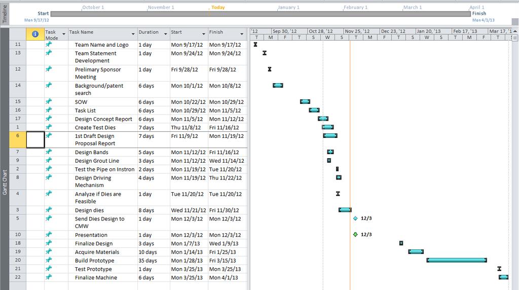
25 APPENDIX I 25 P a g e
26 APPENDIX II WBS Task Element Definition 1 0 Geothermal Pipe Bender All work to develop a machine that will bend Geothermal pipe into a U- shaped cross section 2 0 Initiation Work that starts the project 1 Sponsor Assignments Instructor assigns the project and sponsors 2 Team Name and Logo development 3 Preliminary meeting with Sponsor Team members are to develop the team name and logo for their group and deliver to instructor Team meets with a representative of Charles Machine Works, Inc. to understand the problem and requirements for the final product 3 0 Planning Work that plans the process of design 1 Team statement development The development of the problem statement for the problem set forth by Ditch Witch 2 Gather Background Team gathers background on the problem and conducts research on potential solutions. This also includes patent searches. 3 Statement of Work The development of the a narrow definition of the problem and a definition of what the final machine will consist of 4 Task list Development of a list of deliverables 5 Business Plan Agriculture Economic Team develops a financial analysis and business plan for the project 6 Project Website Develop a website that displays the project in its entirety 7 Design Concept Report Development of preliminary design concepts for the machine 8 Testing Test the HDPE pipe to make sure that the preliminary design concept if feasible and adjust design if needed 9 Design Proposal Report Deliver a compiled analysis that includes SOW, Task List, Business Plan, and Design Concepts that will be presented to the sponsor 10 Design Proposal Oral Team will present an oral presentation 26 P a g e
27 Presentation to sponsor, instructors, and department head that will show the proposal of the project 4 0 Execution The actual execution of the project 1 Finalization of design proposal Team works with sponsor to make final adjustments to proposed machine so assembly can begin 2 Acquire Materials Gather all materials to build machine. This includes hardware and facility. Ditch Witch has offered to help in the building of things such as the dies that would be difficult to do in the BAE lab 3 Development of Prototype Involves the actual development of the geothermal pipe bender 4 Testing Evaluate the prototype and test for defects 5 Final Prototype Development Finalization of prototype so it can be delivered to client 6 Final Report Deliver final report that includes revised design proposal report and final design of machine 7 Demonstration Final prototype is demonstrated and presented to sponsor, instructors, peers, and department head 27 P a g e
28 APPENDIX III Patents BEFORE 1992: These patents are out of date but are relevant to our project and a good source of ideas. The following patents are either in relation or a continuation of each other. They describe a method for bending circular shaped cross-sectional thermoplastic pipe liner into U-shaped cross-sectional liner temporarily, to then be placed into the pipe and reformed into its original circular cross-sectional shape. The pipe liner is deformed through a process involving rollers and heat. After the liner is placed inside the desired pipe it goes through a pressure and heating process. The following figures illustrate the process for the patents below. 28 P a g e
29 Patent number: (Pipe Liner Process) Filing date: Apr 29, 1988 Issue date: Jan 22, 1991 Patent number: (Method and apparatus for deforming reformable tubular pipe liners) Filing date: Jul 27, 1987 Issue date: Sep 5, 1989 Patent number: (Apparatus for deforming plastic tubing for lining pipe) Filing date: Jan 19, 1989 Issue date: Mar 12, 1991 Patent number: (Pipe lining process) Filing date: Nov 21, 1990 Issue date: Feb 25, 1992 AFTER 1992: These patents are still to date and need to be taken into account when designing. Patent number: (Method and apparatus for deforming reformable tubular pipe liners) Filing date: Aug 9, 1990 Issue date: Aug 30, 1994 This patent is for a process to deform pipe liners to line new and old pipe into a U-shape to be placed and then unfolded within the pipe that is needed to be lined, so the fit is tight. 29 P a g e
30 Our project shares similar ideas with the use of rollers, although the main difference with this patent and our project is the use of heat and the use of unusually shaped rollers. The pipe is continuously extruded and heated then cooled during the process of deformation using rollers and guidance rollers. The following figures show the overall process and the guidance rollers. 30 P a g e
31 Patent number: (Process for installing a pipe liner) Filing date: Sep 17, 1996 Issue date: Jan 19, 1999 This patent is for a process to install a liner into a pipe of same diameter. With this process, a cylindrical pipe of high density polyethylene is formed into a smaller W-shaped crosssection to then insert into a pipe for lining. The liner is deformed into a W-shape cross section so external assistance or bindings does not have to be utilized to keep it into that shape. To deform, the cylindrical pipe is inserted into a series of three axially spaced rollers under a temperature of about 70 C. Once the pipe is deformed, it is inserted into the pipe that is to be lined. Steam is flowed through and applied to the W-shaped pipe to deform back to the original cylindrical shape. The following figures illustrate the W-shaped cross-sectional area and the rollers in the deforming process: 31 P a g e
32 Patent number: (Method of deforming an initial pipe having a circular crosssection into a U-shaped section and device for carrying out the method) Filing date: May 7, 1999 Issue date: Sep 19, 2000 The relevance of this patent is it involves a process for making a circular shaped crosssectional into a U-shaped cross-section. This pipe deformation process involves circular shaped cross-sectional being placed into dies to make a U-shaped cross-sectional. This patent does not mention what this pipe is used for and does not describe a process of reopening into its original circular cross-section. The following figures illustrate how the dies bend the pipe. 32 P a g e
33 These patents are relevant because they involve forming circular pipe into a U-shaped cross section. This shape reduces the overall outer diameter for inserting the pipe into another pipe. This is done for the repair of underground sewer, water, gas and similar grounds. They involve heating the pipe to allow for deforming the pipe to proper shape. The forming is done through a multitude of rollers and dies. After the shape is obtained they are cooled back to help the pipe maintain the U-shape. 33 P a g e
 Shaft length (in) Shaft Volume (in 3 ) Top 1.25 10 12.")
 Number of Dies Top 15.66128839 8 125.290 167.393 292.684 Bottom 14.7703351 8 118.163 130.206 248.369 Assembly --- 16 243.")
34 APPENDIX IV- Calculations Die Assembly Weight Die Radius 1 (in) Radius 2 (in) Diameter of Saddle (in) Thickness (in) Volume (in 3 ) Top Bottom Shaft Shaft Shaft Diameter (in) Shaft length (in) Shaft Volume (in 3 ) Top Bottom Assembly Die and Shaft Volume (in 3 ) Density (lb/in 3 ) Total Weight 1 Die (lb) Top Bottom Total Die Assembly Total Weight of 1 Die (lb) Number of Dies Top Bottom Assembly Die Total Weight of Dies (lb) Total Weight of Die Support (lb) Total Weight (lb) 34 P a g e
35 % of actual forces for each roller (Slow) Actual forces for each roller (Fast) Force Required To Move Pipe Through System Force Required to Move Pipe Equation Values Units Coefficient of Friction (c f ) User Input 0.3 Angle of Force (θ) User Input degrees Percent Change User Input 84.56% percent Max Force User Input 800 lb f Inputs for Design I Roller Force (f) Units Equation Force Required (f required ) Units lb f lb f lb f lb f lb f lb f lb f lb f lb f lb f lb f lb f lb f lb f lb f lb f lb f lb f Design I Fast Roller Force (f) Units Equation Force Required (f required ) Units lb f lb f lb f lb f lb f lb f lb f lb f lb f lb f lb f lb f lb f lb f lb f lb f lb f lb f Design I Slow 35 P a g e
36 % of actual forces for each roller (Slow) Actual forces for each roller (Fast) Force Required to Move Pipe Equation Values Units Coefficient of Friction (c f ) User Input 0.3 Angle of Force (θ) User Input 29.5 degrees Percent Change User Input 84.56% percent Max Force User Input 800 lb f Inputs for Design II Roller Force (f) Units Equation Force Required (f required ) Units lb f lb f lb f lb f lb f lb f lb f lb f lb f lb f lb f lb f lb f lb f lb f lb f lb f lb f Design II Fast Roller Force (f) Units Equation Force Required (f required ) Units Design II Slow lb f lb f lb f lb f lb f lb f lb f lb f lb f lb f lb f lb f lb f lb f lb f lb f lb f lb f Design Split Design Force required to move pipe through system Speed of system Fast (25 fpm) Actual Force in*lb f Force with 1.5 Safety Factor in*lb f Slow (10 fpm) in*lb f in*lb f Fast (25 fpm) in*lb f in*lb f Solid Design Slow (10 fpm) in*lb f in*lb f 36 P a g e
37 Split Design Solid Design Torque Required By Drive Motor Torque Required for Drive Motors Equation Values Units Diameter of Roller User Input 8 in Coefficient of Friction [between drive roller and pipe] (c f ) User Input 0.5 Angle of Force between drive roller and pipe (θ) User Input 1 degrees Total force for equal max force on all rollers From Force on Rollers Sheet lb f Total force for actual forces for each roller From Force on Rollers Sheet lb f Total force for % of actual forces for each roller From Force on Rollers Sheet lb f Max Force From Force on Rollers Sheet 800 lb f Percent Change From Force on Rollers Sheet 84.56% Percent Normal Force exerted by roller (Max) Normal Force exerted by roller (Actual) Normal Force exerted by roller (% Actual) Torque of motor to produce force required (Max) Design I Fast and Slow lb f lb f lb f in*lb f Torque of motor to produce force required (Actual) in*lb f Fast Torque of motor to produce force required (% Actual) in*lb f Slow Torque Required for Drive Motors Equation Values Units Diameter of Roller User Input 8 in Coefficient of Friction [between drive roller and pipe] (c f ) User Input 0.8 Angle of Force between drive roller and pipe (θ) User Input 5 degrees Total force for equal max force on all rollers From Force on Rollers Sheet lb f Total force for actual forces for each roller From Force on Rollers Sheet lb f Total force for % of actual forces for each roller From Force on Rollers Sheet lb f Max Force From Force on Rollers Sheet 800 lb f Percent Change From Force on Rollers Sheet 84.56% Percent Normal Force exerted by roller (Max) lb f Normal Force exerted by roller (Actual) lb f Normal Force exerted by roller (% Actual) Torque of motor to produce force required (Max) lb f in*lb f Torque of motor to produce force required (Actual) in*lb f Fast Torque of motor to produce force required (% Actual) in*lb f Slow Design II Fast and Slow Design Split Design Torque of motor to produce force required Speed of system Fast (25 fpm) Actual Torque in*lb f Torque with 1.5 Safety Factor in*lb f Slow (10 fpm) in*lb f in*lb f Fast (25 fpm) in*lb f in*lb f Solid Design Slow (10 fpm) in*lb f in*lb f 37 P a g e
38 Shaft Design Shaft Design Equation Values Units Distance from force to center of bearing User Input 4.25 in Force on shaft User Input 800 lb f Diameter of shaft User Input 1.25 in To calculate stress (σ) for shaft Moment (M) (Force on shaft) * Distance 3400 in*lb f Centroid ( C ) (Diameter of shaft)/ in Moment of Inertia (I) in 4 Bending Stress (σ) psi Bearing Analysis Bearing Analysis Equation Values Units Diameter of Roller User Input 1.5 in Expected life of Bearing User Input 10 years Force on shaft User Input 800 lb f Velocity (given) (10ft/min)* in/min Radius of Roller d/ in Circumference of Roller 2*pi()*r in Number of Revolutions per minute Velocity/Circumference rev/min Number of hours operated per year (# hour/week)*(# weeks/year) min/year Revolutions per Life (rev/min)*(# min operation/year)*(# years/life) rev/life Force on bearings (Force on shaft)/(# bearings supporting shaft) 400 lb f To calculate C 10 for bearing X D (revolutions/life)/(revolutions rated life) R D (reliability) F D (Force on shaft)/(2 bearings) 400 lb f x 0 Look up value for bearing type 0.02 θ Look up value for bearing type a Look up value for bearing type 3 b Look up value for bearing type a f Assume value 1.2 C P a g e
39 APPENDIX V- Economic Analysis GeoFold Premium Geothermal Well Product Business Plan I. Executive Summary The Concept Charles Machine Works, Inc. is developing an new geothermal well casing design that has the potential to decrease home owner utility costs by up to four times the savings already realized with geothermal heating and cooling systems. This new well casing, GeoFold, will decrease the amount of geothermal wells needed to achieve the same efficiency the current systems exhibit. GeoFold may also decrease the amount of time needed to install these geothermal wells. GeoFold will do this by being much more efficient than the conventional geothermal wells, thus needing fewer wells for each system installed. Background Vertical geothermal wells today utilize a u-loop design which allows water to pass through them and release or absorb heat depending on the time of year. This process is much more efficient than HVAC units, but it could be improved. GeoFold will eliminate much of the grout, which hinders the u-loop system s efficiency. The u-loop systems normally require three wells for a residential home where GeoFold may reduce that number to only two wells or possibly one. GeoFold will do this while maintaining, if not increasing, the efficiency geothermal systems currently exhibit. The Company and Management Team Charles Machine Works, Inc., also known as CMW, began in the late 1940 s by Ed Malzhan in Perry, Oklahoma with the creation of a new trenching machine. CMW is an industry leader in the trenching, compact utility machines, trenchless directional drilling, vacuum excavation, and underground utility location areas. CMW is still located in Perry, Oklahoma where their world headquarters and manufacturing facilities are housed. Their products are marketed at Ditch Witch products through their dealer network. CMW has been at the forefront of innovation in their field, twice being named one of the best American-made products in the world by Fortune magazine. CMW is currently under the direction of Tiffany Sewell-Howard as CEO and Edwin Malzahn as Chairman and President. GeoFold is currently being developed under Mr. Kelvin Self. The Industry The geothermal industry falls under the space heating and cooling industry umbrella. This industry has seen near 2.5% growth over the last ten years and is expected to increase that growth to over 3% in by GeoFold will build on the latest technological advances in geothermal pipe by creating a more efficient well casing design which will increase the thermal conductivity of each well resulting in a more efficient overall system and greater savings to the homeowner. Retail trade, education, and government account for the majority of the purchases in the industry with plastic pipe and heat exchanger manufacturers accounting for most inputs. The Market The target market for the GeoFold is primarily the geothermal well installers, but also the end-users or homeowners and business owners. GeoFold could be easier to install 39 P a g e
40 than the u-loop system because of the requirement of fewer wells. It will also be much more efficient allowing the end-user to recover the investment must quicker and realize greater savings through the life of the system. The Competition While the only current competition for GeoFold is the current u-loop method, GeoFold will be a premium geothermal pipe as a result of the greater efficiency of systems using GeoFold and will warrant a higher price. Given this higher initial price GeoFold will likely only attract 1% of the target market in the first full year of production. Even the 1% is enough to realize a gross profit of over $2 million from 7,500 wells installed. There are several unknown variables that could alter than profit number, but none to the point of eliminating it. GeoFold will slowly grow its market share into single digit growth after 3-5 years once consumers can see the added benefits of this premium product. Competitive Position Charles Machine Works, Inc. has an impeccable reputation in the underground construction industry. This reputation and their attention to the consumer will not go away once in the geothermal industry. The developers of GeoFold will make certain the premium product is as advertised prior to market entry and the network of Ditch Witch dealers will insure the customers are satisfied once the product leaves their dealership. GeoFold will be marketed as a premium geothermal well product. Initially the product will be distributed through the Ditch Witch network throughout the United States. CMW will also join with two well known entities in the geothermal industry. The first of these is the International Ground Source Heat Pump Association which is located on the Oklahoma State University campus in Stillwater, Oklahoma and has access to the most current advancements in the geothermal industry. A partnership with this industry association would prove invaluable. The second of these partnerships is with the world s largest and most progressive manufacturer of geothermal heat pumps which is ClimateMaster who is headquartered in Oklahoma City, Oklahoma. The pairing of the most advanced geothermal well product with the largest heat pump manufacturer could propel the sales of GeoFold past expectations and allow CMW to realize a much higher return on their investment in GeoFold. Operations GeoFold will be manufactured and shipped from the CMW manufacturing facility in Perry, Oklahoma initially. Manufacturing the product at the headquarters will allow the research and development team to closely monitor the process and insure that no GeoFold pipe leaves Perry unless it is of the highest quality. Once the process is perfected the manufacturing may be expanded by the sale of creasing devices to Ditch Witch dealerships or even geothermal well installers. Charles Machine Works already has organizational technology in place to assist in the GeoFold process and the company s years of manufacturing will prove invaluable in creating the highest quality product possible. The Future GeoFold is predicted to harness 1% of the target market which would total 7,500 geothermal wells and over 2 million feet of GeoFold pipe. This market share is expected to rise slowly for the first few years until the market share growth realizes yearly single digit gains. GeoFold will continually be monitored and improved as 40 P a g e
41 needed to keep up with the industry. GeoFold technology will be protected by the issuance of a United States Patent in the near future. Financials GeoFold will realize a pre-tax gross margin of $2,214,450 in the first year and each year thereafter with only a 1% market share. The investment in GeoFold is currently worth $13,748,538 to Charles Machine Works when considering 10 years of GeoFold sales. These numbers could rise once the increased cost savings of systems utilizing GeoFold are realized and advertised. 41 P a g e


42 42 P a g e


43 43 P a g e


44 44 P a g e

45 45 P a g e
Geothermal Pipe Bending
 Geothermal Pipe Bending Marshall Oldham Ryan Turner Sarah Reiss Prepared for Charles Machine Works, Inc. Mission Statement D.T.E. is dedicated to coming up with creative and innovative designs with our
Geothermal Pipe Bending
 Geothermal Pipe Bending Marshall Oldham Ryan Turner Sarah Reiss 2013 Spring Design Report Prepared for Charles Machine Works, Inc. TABLE OF CONTENTS Mission Statement.3 Introduction to Problem...3 Problem
Geothermal Pipe Bending
 Geothermal Pipe Bending Marshall Oldham Ryan Turner Sarah Reiss Prepared for Charles Machine Works, Inc. Mission Statement D.T.E. is dedicated to developing creative and innovative designs with our client
Members: Sponsor: Dalton Hamilton Preston-Eastin Levi Edens Kenneth Mui Brice Abbott
 Members: Dalton Hamilton Levi Edens Brice Abbott Sponsor: Preston-Eastin Kenneth Mui Mission Statement Wolf Pack Engineering strives to provide our customer with innovative solutions. We take the problem
External Hard Drive: A DFMA Redesign
 University of New Mexico External Hard Drive: A DFMA Redesign ME586: Design for Manufacturability Solomon Ezeiruaku 4-23-2013 1 EXECUTIVE SUMMARY The following document serves to illustrate the effects
SAE Mini BAJA: Suspension and Steering
 SAE Mini BAJA: Suspension and Steering By Zane Cross, Kyle Egan, Nick Garry, Trevor Hochhaus Team 11 Progress Report Submitted towards partial fulfillment of the requirements for Mechanical Engineering
Design of a High Pressure System to Aid Horizontal Directional Drill Bit Steering. Dustin Holden Curtis Johnson Brandon Kimbrell Kristin Stephens
 Design of a High Pressure System to Aid Horizontal Directional Drill Bit Steering Dustin Holden Curtis Johnson Brandon Kimbrell Kristin Stephens Hole Mole The West Central Pump Works, Inc. The West Central
Used Vehicle Supply: Future Outlook and the Impact on Used Vehicle Prices
 Used Vehicle Supply: Future Outlook and the Impact on Used Vehicle Prices AT A GLANCE When to expect an increase in used supply Recent trends in new vehicle sales Changes in used supply by vehicle segment
4023 Senior Design Spring 2017
 4023 Senior Design Spring 2017 Trot n Trailer Senior Design James Collingsworth Konner Kay Skyler Shepherd Colten Leach Trey Minten About the Client Charles Machine Works Inc. produce various types of
BAE 4012 Senior Design Fall 2016
 BAE 4012 Senior Design Fall 2016 Trot n Trailer Senior Design Konner Kay - Team Leader James Collingsworth Skyler Shepherd Colten Leach Trey Minten Project Outline Introduction: (1-5) Problem Outlook:
Automated Lubrication Yields Concrete Results
 A GUIDE TO BETTER LUBRICATION VOLUME 20, NO.1 Automated Lubrication Yields Concrete Results Making and selling concrete is a gritty business. Heavy loads, caustic materials, constant exposure to dust and
Thick Turret Forming Solutions ULTRAFORM ULTRAFORM XT ULTRAFORM FX Original Style
 Expanding Machine Capabilities Thick Turret Forming Solutions ULTRAFORM ULTRAFORM XT ULTRAFORM FX Original Style mate.com/ultraform Part Number 2010 Worldwide headquarters: 1295 Lund Boulevard, Anoka,
FOR IMMEDIATE RELEASE
 Article No. 7433 Available on www.roymorgan.com Roy Morgan Unemployment Profile Friday, 12 January 2018 2.6m Australians unemployed or under-employed in December The latest data for the Roy Morgan employment
Progress Report. Maseeh College of Engineering & Computer Science Winter Kart 2. Design Team Atom Falcone Austin Greene. Nick Vanklompenberg
 Progress Report Maseeh College of Engineering & Computer Science Winter 2016 Kart 2 Design Team Atom Falcone Austin Greene Jesse Majoros Nick Vanklompenberg Jake Waterman Jeffrey Williamson Faculty Advisor
Course. GNEG 1103 Introduction to Engineering. Assignment. Team Design Project. Project Selected. Solar Powered Stereo Cooler. Project Presentation
 Course GNEG 1103 Introduction to Engineering Assignment Team Design Project Project Selected Solar Powered Stereo Cooler Project Presentation April 23, 2014 Team Members Kenny Callis Ronny Akhaphong Alfredo
U.S. manufacturing technology orders kick off 2018 on a high note
 Contact: Penny Brown, AMT, 703-827-5275 pbrown@amtonline.org For Release: March 12th, 2018 U.S. manufacturing technology orders kick off 2018 on a high note Orders for manufacturing technology in January
Planning Advisory Notice
 Capstan hoists, often referred to as catheads, make back-breaking work faster, easier and more productive. They are used for many applications in multiple industries including telecommunications, electric
Energy Performance Information Request Timeline
 Energy Performance Information Request Timeline Project Title: UT Project # Project Manager: Submitted by: Day Submitted: The timeline below outlines a comprehensive list of required documents and when
Toyota s European Exposure How did Toyota s European operations structure create operating exposure?
 Toyota s European Exposure How did Toyota s European operations structure create operating exposure? Toyota s European Exposure It was January 2002, and Toyota Motor Europe Manufacturing (TMEM) had a problem
SCOPE OF WORK WASTEWATER TREATMENT PLANT THE WORLD LEADER IN PIPE JOINING SOLUTIONS
 SCOPE OF WORK WASTEWATER TREATMENT PLANT THE WORLD LEADER IN PIPE JOINING SOLUTIONS THE VICTAULIC DIFFERENCE HOUSING GROOVE GASKET BOLT/NUT GROOVE GROOVED PIPE JOINING TECHNOLOGY How does it work? The
Technical Math 2 Lab 3: Garage Door Spring 2018
 Name: Name: Name: Name: As you may have determined the problem is a broken spring (clearly shown on the left in the picture below) which needs to be replaced. I. Garage Door Basics: Common residential
EDSGN 100: INTRODUCTION TO ENGINEERING DESIGN Section 204 Team #1 BOX CART
 EDSGN 100: INTRODUCTION TO ENGINEERING DESIGN Section 204 Team #1 BOX CART Submitted by: Chang - http://www.personal.psu.edu/cbl5289/ Vinay Murthy - http://www.personal.psu.edu/vum119/ Aidan Fitzpatrick
January Manufacturing Technology Orders Off After a Strong December
 Contact: Bonnie Gurney, AMT, 703-827-5277 bgurney@amtonline.org For Release: March 9, 2015 January Manufacturing Technology Orders Off After a Strong December January U.S. manufacturing technology orders
Human Powered Vehicle Challenge. Problem Formulation and Project Plan Document
 Human Powered Vehicle Challenge By Matt Gerlich, Alex Hawley, Phillip Kinsley, Heather Kutz, Kevin Montoya, Erik Nelson Team 9 Problem Formulation and Project Plan Document Submitted towards partial fulfillment
Robotic Device for Cleaning of Photovoltaic Arrays V2
 Robotic Device for Cleaning of Photovoltaic Arrays V2 Design Team Greg Belogolovsky, Steve Bennett, Istvan Hauer, Salome Morales, Leonid Nemiro Design Advisor Constantinos Mavroidis, Ph.D. Richard Ranky,
SAE Mini BAJA: Suspension and Steering
 SAE Mini BAJA: Suspension and Steering By Zane Cross, Kyle Egan, Nick Garry, Trevor Hochhaus Team 11 Project Progress Submitted towards partial fulfillment of the requirements for Mechanical Engineering
Remote Control Helicopter. Engineering Analysis Document
 Remote Control Helicopter By Abdul Aldulaimi, Travis Cole, David Cosio, Matt Finch, Jacob Ruechel, Randy Van Dusen Team 04 Engineering Analysis Document Submitted towards partial fulfillment of the requirements
ECSE-2100 Fields and Waves I Spring Project 1 Beakman s Motor
 Names _ and _ Project 1 Beakman s Motor For this project, students should work in groups of two. It is permitted for groups to collaborate, but each group of two must submit a report and build the motor
Proven to be better. Development trends in industrial rolling bearings
 Proven to be better Development trends in industrial rolling bearings Contents 1. General trends in power transmission and in machine construction and plant engineering Page 3 2. General trends in rolling
Valvoline Fourth-Quarter Fiscal 2016 Earnings Conference Call. November 9, 2016
 Valvoline Fourth-Quarter Fiscal 2016 Earnings Conference Call November 9, 2016 Forward-Looking Statements This presentation contains forward-looking statements within the meaning of Section 27A of the
A BRAND-NEW LIFT FOR YOUR BUILDING
 A BRAND-NEW LIFT FOR YOUR BUILDING KONE MonoSpace AN INVESTMENT IN YOUR BUILDING S FUTURE Full replacement gives you all the benefits of the latest technology with a visually appealing lift car. As well
A Cost Benefit Analysis of Faster Transmission System Protection Schemes and Ground Grid Design
 A Cost Benefit Analysis of Faster Transmission System Protection Schemes and Ground Grid Design Presented at the 2018 Transmission and Substation Design and Operation Symposium Revision presented at the
How You Benefit From The KC Sealing System A New Definition Of Leaky Flanged Joints Comparison Of Flanged Joint After Bolt-Up...
 Benefits How You Benefit From The KC Sealing System...-1 A New Definition Of Leaky Flanged Joints...-2 Comparison Of Flanged Joint After Bolt-Up...-3 Joining Dissimilar Flange Adapter Types...- Gasket
Magnetostrictive Actuator
 Magnetostrictive Actuator Project Proposal Randall Bateman, Aaron Bolyen, Chris Cleland Alex Lerma, Xavier Petty, Michael Roper December 11, 2015 Overview Introduction Need Statement/Goals Constraints
TUBUS-Series Type TA
 TUBUS-Series Type TA Profile Damper Axial Damping 84 The profile damper type TA from the innovative ACE TUBUS series is a maintenancefree, self-contained damping element made from a special Co-Polyester
Smart Automated Vent Register Using an SMA Spring Actuated Rotary Ratchet
 Smart Automated Vent Register Using an SMA Spring Actuated Rotary Ratchet Mary Molepske, Victor Braciszewski, James Butler, Gregory Caputo, Fan-Ning Cheng, WonHee Kim, Jonathan Luntz, Diann Brei ABSTRACT
Delivery System for Hernia Mesh Fixation
 Delivery System for Hernia Mesh Fixation Design Team Joseph Aaron, Andrew Edgerly Charles O Connell, Charles Sidoti, David Stone Design Advisor Dr. Jeffrey Ruberti Sponsor High Road Medical Abstract The
Coal Mine Safety Shortchanged by Years of Budget Cuts
 Coal Mine Safety Shortchanged by Years of Budget Cuts Congress created the Mine Safety and Health Administration (MSHA) in 1977, placing a new federal focus on miner safety and health. However, the agency's
The Use of Conduction Tracers Vs Bare Tracers Metric Version
 The Use of Conduction Tracers Vs Bare Tracers Metric Version CONDUCTION TRACER BARE TRACERS The term conduction tracing refers to steam tracing systems utilizing a heat transfer compound to thermally bond
Lessons in Systems Engineering. The SSME Weight Growth History. Richard Ryan Technical Specialist, MSFC Chief Engineers Office
 National Aeronautics and Space Administration Lessons in Systems Engineering The SSME Weight Growth History Richard Ryan Technical Specialist, MSFC Chief Engineers Office Liquid Pump-fed Main Engines Pump-fed
Introduction: Problem statement
 Introduction: Problem statement The goal of this project is to develop a catapult system that can be used to throw a squash ball the farthest distance and to be able to have some degree of accuracy with
EDSGN 100. Folding Shopping Cart
 EDSGN 100 Introduction to Engineering Design Section 0, Team #1 Folding Shopping Cart http://www.personal.psu.edu/jzb31/edsgn100_su16_section0_team1_dp1.pdf Submitted by: Jacob Barclay, Abhishek Ganta,
GONE TOO FAR: SOARING HYDRO BILLS OFFSET CONSERVATION EFFORTS AND HURT CONSERVERS MOST
 GONE TOO FAR: SOARING HYDRO BILLS OFFSET CONSERVATION EFFORTS AND HURT CONSERVERS MOST Brady Yauch Economist and Executive Director of Consumer Policy Institute (416) 964-9223 ext 236 bradyyauch@consumerpolicyinstitute.org
1. INTRODUCTION 3 2. COST COMPONENTS 17
 CONTENTS - i TABLE OF CONTENTS PART I BACKGROUND 1. INTRODUCTION 3 1.1. JUSTIFICATION OF MACHINERY 4 1.2. MANAGERIAL APPROACH 5 1.3. MACHINERY MANAGEMENT 5 1.4. THE MECHANICAL SIDE 6 1.5. AN ECONOMICAL
Folding Shopping Cart Design Report
 Folding Shopping Cart Design Report EDSGN 100 Section 010, Team #4 Submission Date- 10/28/2013 Group Image with Prototype Submitted by: Arafat Hossain, Mack Burgess, Jake Covell, and Connor Pechko (in
Robot Preparation for the VEX World Championship/ US Open. Lessons learned over the past 6 years by David Kelly 2013 VWC, Teacher of the Year
 Robot Preparation for the VEX World Championship/ US Open Lessons learned over the past 6 years by David Kelly 2013 VWC, Teacher of the Year Re-designing Re-designing your robot to a new concept yields
An innovative solution for water and sewer installation AXIS. Guided Boring System
 An innovative solution for water and sewer installation AXIS TM Guided Boring System A need for new installation options A growing number of water and sewer projects are required to be placed precisely
NEWS Release. U.S. Manufacturing Technology Orders. Year-to-date U.S. manufacturing technology orders up 4.1% over 2011
 U.S. Manufacturing Technology Orders A statistical program of AMT NEWS Release FOR RELEASE: October 8, 2012 Contact: Pat McGibbon, AMT, 703-827-5255 Year-to-date U.S. manufacturing technology orders up
ABB POWER SYSTEMS CONSULTING
 ABB POWER SYSTEMS CONSULTING DOMINION VIRGINIA POWER Offshore Wind Interconnection Study 2011-E7406-1 R1 Summary Report Prepared for: DOMINION VIRGINIA POWER Report No.: 2011-E7406-1 R1 Date: 29 February
Lesson Plan. Time This lesson should take approximately 180 minutes (introduction 45 minutes, presentation 90 minutes, and quiz 45 minutes).
.") Introduction to Biodiesel Fuel Applications Manufacturing Engineering Performance Objectives After completing this lesson, students will be able to discuss the purpose and applications of biodiesel fuel
Introduction to Biodiesel Fuel Applications Manufacturing Engineering Performance Objectives After completing this lesson, students will be able to discuss the purpose and applications of biodiesel fuel
LEAD SCREWS 101 A BASIC GUIDE TO IMPLEMENTING A LEAD SCREW ASSEMBLY FOR ANY DESIGN
 LEAD SCREWS 101 A BASIC GUIDE TO IMPLEMENTING A LEAD SCREW ASSEMBLY FOR ANY DESIGN Released by: Keith Knight Kerk Products Division Haydon Kerk Motion Solutions Lead Screws 101: A Basic Guide to Implementing
Multicompartment Fiberglass Underground Storage Tanks
 Multicompartment Fiberglass Underground Storage Tanks Xerxes Multicompartment Tanks A superior choice for multiple storage needs Whether a customer needs two tanks in one, or three tanks in one, the Xerxes
Monro, Inc. Second Quarter Fiscal 2019 Earnings Call. October 25, 2018
 Monro, Inc. Second Quarter Fiscal 2019 Earnings Call October 25, 2018 Safe Harbor Statement and Non-GAAP Measures Certain statements in this presentation, other than statements of historical fact, including
Simulating Rotary Draw Bending and Tube Hydroforming
 Abstract: Simulating Rotary Draw Bending and Tube Hydroforming Dilip K Mahanty, Narendran M. Balan Engineering Services Group, Tata Consultancy Services Tube hydroforming is currently an active area of
Engineering Design Process for BEST Robotics JANNE ACKERMAN COLLIN COUNTY (COCO) BEST & BEST OF TEXAS ROBOTICS
 BEST & BEST OF TEXAS ROBOTICS") Engineering Design Process for BEST Robotics JANNE ACKERMAN COLLIN COUNTY (COCO) BEST & BEST OF TEXAS ROBOTICS Agenda Getting Started Lessons Learned Design Process Engineering Mechanics 2 Save Time Complete
Engineering Design Process for BEST Robotics JANNE ACKERMAN COLLIN COUNTY (COCO) BEST & BEST OF TEXAS ROBOTICS Agenda Getting Started Lessons Learned Design Process Engineering Mechanics 2 Save Time Complete
characteristics, including the ability to turn through 180 degrees for an increase in backing thrust.
 6 Turning CRP Azipod gives a boost to point marine propulsion efficiency Tomi Veikonheimo, Matti Turtiainen Almost as old as the invention of the screw propeller itself, the concept of contra-rotating
SAE Baja - Drivetrain
 SAE Baja - Drivetrain By Ricardo Inzunza, Brandon Janca, Ryan Worden Team 11 Engineering Analysis Document Submitted towards partial fulfillment of the requirements for Mechanical Engineering Design I
Manufactured in the U.S.A. HVAC Rollforming and Sheet Metal Equipment
 Manufactured in the U.S.A. HVAC Rollforming and Sheet Metal Equipment Where superior duct work begins. The Vicon line of HVAC Rollforming and Sheet Metal Equipment is the industry proven solution for all
Applications in Design & Engine. Analyzing Compound, Robotic Machines
 v2.1 Compound Machines ering Applications in Design & Engine Analyzing Compound, Robotic Machines Educational Objectives At the conclusion of this lesson, students should be able to: Understand the relationship
Cost Benefit Analysis of Faster Transmission System Protection Systems
 Cost Benefit Analysis of Faster Transmission System Protection Systems Presented at the 71st Annual Conference for Protective Engineers Brian Ehsani, Black & Veatch Jason Hulme, Black & Veatch Abstract
A Recommended Approach to Pipe Stress Analysis to Avoid Compressor Piping Integrity Risk
 A Recommended Approach to Pipe Stress Analysis to Avoid Compressor Piping Integrity Risk by: Kelly Eberle, P.Eng. Beta Machinery Analysis Calgary, AB Canada keberle@betamachinery.com keywords: reciprocating
By Renee Changnon, A Brighter Future. TreeHouse Shines Light on Solar Solutions
 By Renee Changnon, rchangnon@nrha.org A Brighter Future TreeHouse Shines Light on Solar Solutions For a rising number of today s consumers, updating their homes means more than just improving the look
Keynote from Andreas Renschler, CEO Volkswagen Truck & Bus GmbH and Yoshio Shimo, President & CEO Hino Motors Ltd.
 Keynote from Andreas Renschler, CEO Volkswagen Truck & Bus GmbH and Yoshio Shimo, President & CEO Hino Motors Ltd.. THE SPOKEN WORD PREVAILS Tokyo, 12.04.2018 Good afternoon. I am Yoshio Shimo, President
Finite Element Analysis of Clutch Piston Seal
 Finite Element Analysis of Clutch Piston Seal T. OYA * F. KASAHARA * *Research & Development Center Tribology Research Department Three-dimensional finite element analysis was used to simulate deformation
New Frontier in Energy, Engineering, Environment & Science (NFEEES-2018 ) Feb
 Feb") RESEARCH ARTICLE OPEN ACCESS DESIGN AND IMPACT ANALYSIS OF A ROLLCAGE FOR FORMULA HYBRID VEHICLE Aayush Bohra 1, Ajay Sharma 2 1(Mechanical department, Arya College of Engineering & I.T.,kukas, Jaipur)
RESEARCH ARTICLE OPEN ACCESS DESIGN AND IMPACT ANALYSIS OF A ROLLCAGE FOR FORMULA HYBRID VEHICLE Aayush Bohra 1, Ajay Sharma 2 1(Mechanical department, Arya College of Engineering & I.T.,kukas, Jaipur)
Introduction. Materials and Methods. How to Estimate Injection Percentage
 How to Estimate Injection Percentage Introduction The Marel IN33-3 injector for pork bellies is a 5 needle, low-pressure conveyor type machine which utilizes a 3-gpm positive displacement pump and control
Foldable Shopping Cart Project
 http://www.personal.psu.edu/mmf206/edsgn100_fa16_section07_team6_dpl.pdf EDSGN 100: Introduction to Engineering Design Foldable Shopping Cart Project Section 07 Team # 6 Submitted by: Ghadah Alamer, Joseph
INFLUENCE OF CROSS FORCES AND BENDING MOMENTS ON REFERENCE TORQUE SENSORS FOR TORQUE WRENCH CALIBRATION
 XIX IMEKO World Congress Fundamental and Applied Metrology September 6 11, 2009, Lisbon, Portugal INFLUENCE OF CROSS FORCES AND BENDING MOMENTS ON REFERENCE TORQUE SENSORS FOR TORQUE WRENCH CALIBRATION
FOLDING SHOPPING CART
 1 EDSGN 100: Introduction to Engineering Design Section 10 Team 6 FOLDING SHOPPING CART Submitted by: Kevin Chacha, Ugonna Onyeukwu, Patrick Thornton, Brian Hughes Submitted to: Xinli Wu October 28, 2013
Factory activity accelerated further in our region this month, posting its highest composite reading since 2011, said Wilkerson.
 FOR RELEASE Thursday, October 26, 17 EMBARGOED FOR A.M. CENTRAL TIME CONTACT: Pam Campbell 45-27-8617 Pam.Campbell@kc.frb.org TENTH DISTRICT MANUFACTURING ACTIVITY POSTS STRONG GROWTH Federal Reserve Bank
Electric Motors and Drives
 EML 2322L MAE Design and Manufacturing Laboratory Electric Motors and Drives To calculate the peak power and torque produced by an electric motor, you will need to know the following: Motor supply voltage:
INTERACTIVE WASTEWATER TREATMENT DISPLAY. Cole Niblett Olivia Broussard Brandy Parks Abigail Parnell
 INTERACTIVE WASTEWATER TREATMENT DISPLAY Cole Niblett Olivia Broussard Brandy Parks Abigail Parnell GROUP PICTURE AGENDA Problem Statement and Background Objectives and Project Scope Conceptual Designs
(12) Patent Application Publication (10) Pub. No.: US 2006/ A1
 Patent Application Publication (10) Pub. No.: US 2006/ A1") US 2006O131873A1 (19) United States (12) Patent Application Publication (10) Pub. No.: Klingbail et al. (43) Pub. Date: Jun. 22, 2006 (54) HIGH PRESSURE SWIVEL JOINT Publication Classification (76) Inventors:
US 2006O131873A1 (19) United States (12) Patent Application Publication (10) Pub. No.: Klingbail et al. (43) Pub. Date: Jun. 22, 2006 (54) HIGH PRESSURE SWIVEL JOINT Publication Classification (76) Inventors:
Electric Power Industry. Team XXXXX: Names of team members omitted on purpose
 Electric Power Industry Team XXXXX: Names of team members omitted on purpose Objectives Electricity quick Facts Brief History of Electricity in US Industry Analysis Firm Analysis: Georgia Power A Coal
The Deployable Gage Restraint Measurement System - Description and Operational Performance
 The Deployable Gage Restraint Measurement System - Description and Operational Performance GARY A. MARTIN ENSCO, INC 5400 PORT ROYAL ROAD SPRINGFIELD, VA 22151 703-321-4513 703-321-7619 (FAX) JEFFREY A.
Motor-CAD End Winding Spray Cooling Model
 Motor-CAD End Winding Spray Cooling Model Description Motor spray cooling is where the end winding is cooled by passing a fluid down the shaft and then firing it at the end winding through nozzles at the
PIP REEE003 Guidelines for General Purpose Non-Lubricated Flexible Couplings
 September 2016 Machinery PIP REEE003 Guidelines for General Purpose Non-Lubricated Flexible Couplings PURPOSE AND USE OF PROCESS INDUSTRY PRACTICES In an effort to minimize the cost of process industry
Automotive Research and Consultancy WHITE PAPER
 Automotive Research and Consultancy WHITE PAPER e-mobility Revolution With ARC CVTh Automotive Research and Consultancy Page 2 of 16 TABLE OF CONTENTS Introduction 5 Hybrid Vehicle Market Overview 6 Brief
Foldable Shopping Cart EDSGN 100 Section 202 Team 3
 Foldable Shopping Cart EDSGN 100 Section 202 Team 3 http://personal.psu.edu/jnb5392/homepage.htm Submitted by: Alex Thomason Christian Sak Jeremy Deppen Jerod Barone Submitted to: Xinli Wu 30 July 2015
VARIABLE DISPLACEMENT OIL PUMP IMPROVES TRACKED VEHICLE TRANSMISSION EFFICIENCY
 2018 NDIA GROUND VEHICLE SYSTEMS ENGINEERING AND TECHNOLOGY SYMPOSIUM POWER & MOBILITY (P&M) TECHNICAL SESSION AUGUST 7-9, 2018 NOVI, MICHIGAN VARIABLE DISPLACEMENT OIL PUMP IMPROVES TRACKED VEHICLE TRANSMISSION
FOR IMMEDIATE RELEASE
 Article No. 7137 Available on www.roymorgan.com Roy Morgan Unemployment Profile Wednesday, 8 February 2017 Over 12 million Australians have jobs for the first time including over 8 million full-time jobs,
Describe Elio Engineering.(Pg -14)
") By Nirali Thakkar Judith Sobotie 1 Question 1 Describe Elio Engineering.(Pg -14) Elio Engineering was started by an individual name Paul Elio who had an idea that of the ABTS(All-Belt- To-Seat) called
By Nirali Thakkar Judith Sobotie 1 Question 1 Describe Elio Engineering.(Pg -14) Elio Engineering was started by an individual name Paul Elio who had an idea that of the ABTS(All-Belt- To-Seat) called
BorgWarner s growing hybrid and electric product portfolio delivers clean, efficient vehicle propulsion
 News Release BorgWarner s growing hybrid and electric product portfolio delivers clean, efficient vehicle propulsion BorgWarner delivers a growing lineup of propulsion solutions for customers electric
Biofuels, Energy Security, and Future Policy Alternatives. Wally Tyner
 Biofuels, Energy Security, and Future Policy Alternatives Wally Tyner Purdue University Ethanol Economics Ethanol has value as energy and as an additive to gasoline The energy content is about 68% of gasoline
7956 Series MatTop Chains Design Manual Series MatTop Chains
 7956 Series MatTop Chains Design Manual 7956 Series MatTop Chains 1 Contents Safety Considerations/Introduction...2-3 Chain Selection - Selection Criteria...4 - Specifying and Part Number Nomenclature...5
AGN 076 Alternator Bearings
 Application Guidance Notes: Technical Information from Cummins Generator Technologies AGN 076 Alternator Bearings BEARING TYPES In the design of STAMFORD and AvK alternators, the expected types of rotor
STAINLESS STEEL MANIFOLDS FOR RADIANT SYSTEMS CREATION AND DIFFUSION OF THE STAINLESS STEEL MANIFOLD USE DIAGRAMS OF STAINLESS STEEL MANIFOLDS
 STAINLESS STEEL MANIFOLDS FOR RADIANT SYSTEMS CREATION AND DIFFUSION OF THE STAINLESS STEEL MANIFOLD USE DIAGRAMS OF STAINLESS STEEL MANIFOLDS www.itap.it CREATION AND DIFFUSION OF THE STAINLESS STEEL
PRESS RELEASE. Significant fuel savings and rapid payback shown for rail flywheel hybrid technology. 16 June 2015
 PRESS RELEASE 16 June 2015 Significant fuel savings and rapid payback shown for rail flywheel hybrid technology Research and development conducted by Ricardo, Artemis Intelligent Power and Bombardier Transportation
FILLING UP WITH HYDROGEN Matthew J. Fairlie, Paul B. Scott Stuart Energy USA 3360 East Foothill Blvd Pasadena, California
 FILLING UP WITH HYDROGEN 2000 Matthew J. Fairlie, Paul B. Scott Stuart Energy USA 3360 East Foothill Blvd Pasadena, California 91107-3111 Abstract Filling Up with Hydrogen 2000 is Stuart Energy s prototype
IMPROVING MOTOR SYSTEM EFFICIENCY WITH HIGH EFFICIENCY BELT DRIVE SYSTEMS
 IMPROVING MOTOR SYSTEM EFFICIENCY WITH HIGH EFFICIENCY BELT DRIVE SYSTEMS Contents Introduction Where to Find Energy Saving Opportunities Power Transmission System Efficiency Enhancing Motor System Performance
The Team. Taylor Cole Nick Jacobsen Travis Biggerstaff
 Project Overview The Team Taylor Cole Nick Jacobsen Travis Biggerstaff MacDon Industries Ltd. Winnipeg, MB OEM Company Windrowers Combine Headers All pictures courtesy of MacDon Industries Ltd. MacDon
GENERAL PLANNING GUIDELINES MULTI-BAY CAR WASH
 GENERAL PLANNING GUIDELINES MULTI-BAY CAR WASH Information to be considered when planning your Multi-Bay Car Wash. The information presented id for a 4 6 bay coin operated car wash. It is based on past
FURTHER TECHNICAL AND OPERATIONAL MEASURES FOR ENHANCING ENERGY EFFICIENCY OF INTERNATIONAL SHIPPING
 E MARINE ENVIRONMENT PROTECTION COMMITTEE 67th session Agenda item 5 MEPC 67/5 1 August 2014 Original: ENGLISH FURTHER TECHNICAL AND OPERATIONAL MEASURES FOR ENHANCING ENERGY EFFICIENCY OF INTERNATIONAL
Mahindra REVA case study
 Mahindra REVA case study Vodafone Global M2M Making the connected car a reality Vodafone Power to you Mahindra REVA case study Mahindra REVA makes the connected car a reality with M2M connectivity from
THE FRANCHISE GIANT. Three Strategies for Competing With the Big Boys DEALERSOCKET.COM/IND
 THE FRANCHISE GIANT Three Strategies for Competing With the Big Boys Franchise dealers see an average 617 percent higher yield in gross profits selling used cars. Independent auto dealerships face a tough
Burn Characteristics of Visco Fuse
 Originally appeared in Pyrotechnics Guild International Bulletin, No. 75 (1991). Burn Characteristics of Visco Fuse by K.L. and B.J. Kosanke From time to time there is speculation regarding the performance
Our mission is to be the best public service transporter for passengers in the city of Kigali using modern, clean and safe urban city buses.
 Kigali Bus Services Ltd. was incorporated in January 2006 in Kigali Rwanda. The Company started operations in March 2007 with just a few buses! We now operate a fleet of 50 Buses throughout Kigali City
The Enhanced Platform
 Power Generation The Enhanced Platform The Next Generation of Industrial Steam Turbines www.siemens.com / energy / steamturbines Advanced Steam Turbine Design Figure 1: Enhanced Platform Design The Enhanced
Demystifying the Use of Frameless Motors in Robotics
 WHITEPAPER Demystifying the Use of Frameless Motors in Robotics TABLE OF CONTENTS EXECUTIVE SUMMARY: THE VALUE OF FRAMELESS MOTORS IN ROBOTICS ENGINEERS: WHY IS THIS ARTICLE FOR YOU? ADVANTAGES OF FRAMELESS
Green Line LRT: Beltline Segment Update April 19, 2017
 Green Line LRT: Beltline Segment Update April 19, 2017 Quick Facts On April 11, 2017, City Council approved Administration s recommendation for the Green Line to be underground in the Beltline from 2 Street