INSTALLATION / START-UP (ROSS PISTON VALVE GLOBE OR ANGLE STYLE)
|
|
|
- Laurence Potter
- 6 years ago
- Views:
Transcription
1
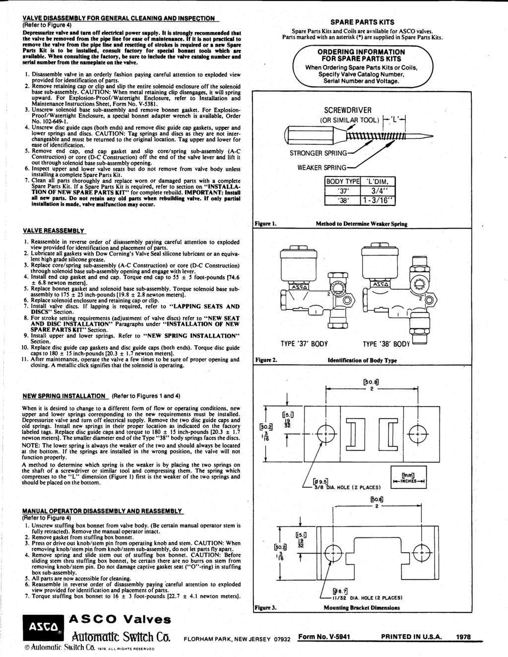
2 INSTALLATION / START-UP (ROSS PISTON VALVE GLOBE OR ANGLE STYLE) Shipment: Prior to shipment, each valve is thoroughly tested and pre-adjusted at the factory to the expected field conditions. Any visible damage to the crate or packaging should be immediately brought to the attention of the shipping company and documented with photographs. Depending upon the valve size, external controls may be attached or in a separate box. The inlet of the main valve is identified with a metal tag. When controls are shipped separately, connections are tagged. Storage: If it is necessary to store the valve before installation, it should be protected from the elements. Inside storage is recommended. If this is not possible, the valve should be protected from dirt, heat, freezing, and direct sunlight. Installation: 1. Carefully remove all shipping materials and check the valve for any other foreign objects. 2. If possible, flush the line before inserting the valve. 3. The valve is tagged with a model and serial number. It is recommended that the serial number be noted in your records as this will be requested by the factory when any technical support or parts replacement is required. Valve serial number: L. 4. Place the valve in line with the flange marked INLET facing the high pressure or supply line. CAUTION: Do not obstruct the vent hole in the center of the bottom cap (#16 for Globe Body valves) or in the differential cylinder bracket (#27 for Angle Body valves). Allow enough clearance above the valve for removal of the stem assembly. 5. If external piping and controls are not attached to the valve when shipped, connect couplings identified with tags that are numbered. The arrow on the pilot valve body points in the direction of flow through the pilot valve. Flow is always away from the top cap of the main valve. The indicator rod (#20) shows the position of the main stem. 6. Attach gauge cocks to the back side of the valve. 7. Complete any necessary wiring on solenoid valves (if applicable). Start-Up: 1. Close the isolation valves (#18) in the control piping. 2. Open the main line gate valve (if installed) on the discharge/downstream side of the valve. 3. Slowly open the main line gate valve (if installed) on the inlet/upstream side of the valve. 4. Open the isolation valves (#18) in the control piping. 5. Loosening the union of the control piping on the top cap side of the speed control valve will help bleed air and give a positive indication when the operating chamber is full. It may be necessary to apply pressure to the valve indicator rod (if provided) with a wrench handle or block of wood until the valve operating chamber is pressurized. 6. No lubrication or adjustment to the valve is required or recommended. The valve has been thoroughly tested at the factory and set to the expected field conditions. ROSS VALVE MFG. CO., INC. 6 OAKWOOD AVE, TROY, NY TEL:
 body with bronze trimbody: 2\" - 36\" - Cast")
 2. Cast steel or ductile iron body and stainless steel trim 3.")
3 PUMP CONTROL VALVE Purpose: Control surges caused by pump starting/stopping Model Number: 42WRS Sizes: 2-48 Type: Nonthrottling system Primarily Controlled By: Electricity Located: In line Purpose: To control surges caused by pump starting and stopping Inlet Pressure: Maximum: 300 psi Inlet Pressure: Minimum: 5 psi Construction: Cast iron (semi-steel) body with bronze trimbody: 2" - 36" - Cast iron (semi-steel) with bronze trim 40" - 48" - Ductile iron, with bronze/ stainless steel trim Control Devices: Strainer: Model 5F-2 Valves: Needle: (Closing Control) Needle: (Opening Control) Pilot: Solenoid: 3 Way Other System Components: Limit Switch: Wired to normally closed contact Options 1. Angle body design (90 degree) 2. Cast steel or ductile iron body and stainless steel trim 3. Two 2-Way solenoids - To hold the piston in an intermediate position 4. Teflon coated cylinders Customized Features Any one or a selection of the features can be added to the basic pump control valve. Code MC2001P - Pump Control Panel: Computer Based- 2nd Generation CP - Pump Control Panel: Mechanical Relay PR - Pressure Reducing Valve BP - Back Pressure Sustaining Valve CI - Check Feature (Internal) SO - Solenoid Pilot Valve: 2 Way Emergency Close ES - Higher Efficiency Strainer TD - Time Delay Relay PS - Pressure Switch Factory: Telephone (518) ; Fax (518) Ross engineers customize the basic 42WRS to accommodate individual needs. Basic Applications 1. Minimize pump starting and stopping surges. 2. Prevent reverse flow when the controls are de-energized. If: Pump pressure is less than system pressure or the pump is not running Ross Main Valve will: Remain closed. When: Pump starts Ross Main Valve will: Open slowly after the pump start up to minimize possible surges. When: Pump stops Ross Main Valve will: Already be 95% closed to minimize possible surges. P - 1
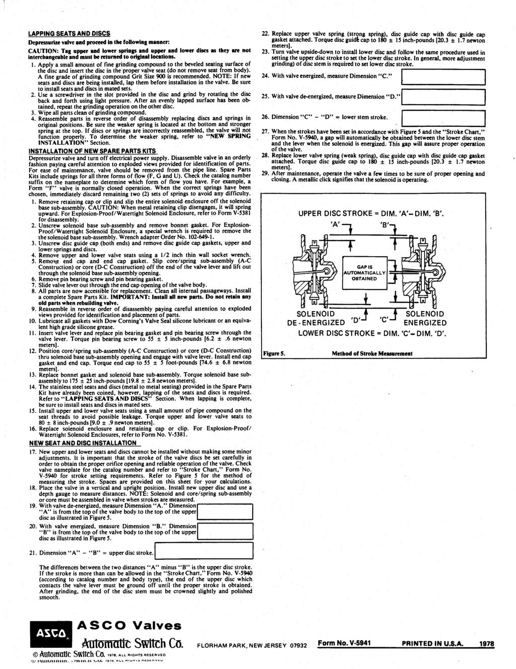
4 GENERAL OPERATION OF A ROSS VALVE (Model 42WR-S) All Ross Valves operate with the same basic hydraulic principles and are composed of two essential parts: the main valve (through which the main flow of water passes), and a control device (which is piped externally on the main valve). The control device is varied to suit the specific type of operation desired. In this case, it includes a 3-way and a 2-way (optional) electrically-actuated, non-throttling solenoid valve. Its basic function is to control the pressure in the "operating chamber" (the area above the large piston in the main valve). The main valve, no matter what its function, is of the same fundamental design. A stem, which carries a seat disc between a large and a small piston, is free to move along the axis of the cylinders. This movement corresponds to the opening and closing of the valve, as follows: Opening - Typically, when the pump is started the solenoid valves in the control circuit are energized. This arranges the solenoid porting in such a way that the operating chamber is emptied. Line pressure, acting on the exposed areas of the stem, produces a net upward hydraulic force which lifts the stem assembly (including the seat disc), and allows water to flow unrestricted through the valve. Closing - When the porting through the solenoid pilot valves is electrically changed, the inlet pressure forces the operating chamber to fill with water. As the pressure in the operating chamber builds up, the stem assembly is forced to move down into its seat, preventing flow through the valve. (Note: When supplied, the 2-way solenoid is used for "Emergency Close" situations. In the event of a power failure, the 2-way solenoid will open to fill the operating chamber quickly, regardless of what the smaller, 3-way solenoid is doing.) These are the basic principles used in all of our valves. ROSS VALVE MFG. CO., INC. - P.O. BOX 595, 6 OAKWOOD AVE. - TROY, NY TEL (518) FAX (518)
5 Operation PUMP CONTROL VALVE Model Number: 42WRS Control Unit A carefully balanced system of controls along an external piping circuit monitors flow in and out of the operating chamber and, consequently, the piston open/closed position relative to the pump stopping/starting. It includes: a. External Piping with several basic segments which run from the: 1. Inlet side of the main valve to a pipe leading into the operating chamber. 2. Outlet side of the main valve to a pipe leading out of the operating chamber. 3. Inlet/outlet external pipes into the operating chamber. b. Normal Solenoid pilot valve Three openings and two ports control pressure in the operating chamber 1 Opening - to the operating chamber. 1 Opening - to the line (controlled by 1 port). 1 Opening - to waste (controlled by 1 port). c. Emergency Close-Solenoid pilot valve - (Customized feature used on most installations.) Two openings and one port control flow from the operating chamber. d. Needle Valves - Two valves control maximum flow: 1 Needle - Into the operating chamber. 1 Needle - Out of the operating chamber. e. Limit Switch - Switches on and off by movement of a valve indicator. Operation By slowly going full open after the pump starts and 95% closed before the pump stops, the valve effectively provides the system with a smooth stopping and starting flow. A. In order to open the main line valve, the 1. Control switch contacts close together, energizing the relay coil R. 2. Two R contacts close together energizing the: a. Normal solenoid coil S 3. b. Emergency (backup) solenoid coil S 2. c. Pump motor starter coil M. 3. Pump starts. 4. When the pump develops enough line pressure, the valve slowly opens. 5. As the valve opens, limit switch LS closes and parallels the R contact to be in series with the: a. Emergency solenoid pilot S 2. b. Pump motor starter M. B. In order to close the main line valve, the 1. Control switch contacts open, de-energizing the relay coil R. 2. Two R contacts open and de-energize only the normal solenoid coil S 3. Factory: Telephone (518) ; Fax (518) Main line valve begins to close. 4. Limit switch, whose contacts are still closed, continues to energize the: a. Emergency solenoid coil S 2. b. Pump motor starter coil M. 5. Pump continues running. 6. Main line valve reaches 95% closed causing the limit switch contacts to open and de-energizing the: a. Emergency solenoid coil S 2. b. Pump motor starter M. 7. Pump stops. THIS EXAMPLE IS VERY BASIC. Refinements such as stepped voltage starting, thermal and reverse phase motor protection, interlock to prevent accidental start from limit switch, etc., are desirable. ROSS ENGINEERS ARE AVAILABLE to make suggestions. Simple example incorporating second 2 Way Solenoid (customized) feature. CS = Control Switch M = Motor Starter Relay R = Double Pole Normally Open Relay LS = Limit Switch (Shown in Valve Closed Position) S 3 = Normal Solenoid Coil S 2 = Emergency (backup) Solenoid Coil P - 9
6 6 OAKWOOD AVENUE - TROY, NEW YORK, TEL. (518) POST OFFICE BOX TROY, NEW YORK, FAX (518) WEBSITE: - E-MA L: sales@rossvalve.com 42WR-S RJC 44EC Model 42WR-S PUMP CONTROL VALVE (ELECTRIC CHECK) WITH EMERGENCY CLOSE FEATURE
7 DIMENSIONS Globe Body Minimum Clearances Piston Valve Sizes: 4-36 Size (Inches) O P 4 1 /2 5 1 /2 6 1 / Note 1. Dimension O is clearance for removal of the top cap and piston for repacking the main valve. Additional working space for the convenience of the service man should be considered above as well as around the valve. 2. Dimension P as listed is the desirable clearance under the valve for removal of the STANDARD bottom cap. This dimension may be reduced to 1 inch for all valves on special applications. Note A. Do not obstruct vent hole located at the center of the bottom cap. B. Consideration should be given for installation of valves 14 or larger under manhole in the roof of the valve vault or for additional clearance above the valve since a mechanical hoist will probably be required for removal of the piston. An eye bolt or hook cast in the cover slab over the center of the valve is useful. C. If clearance under the valve is limited, dimensions O and P can be modified. Consult the factory concerning special applications.

8 4 qwer Direct Acting General Service Solenoid Valves Brass or Stainless Steel Bodies 1/8" to 1/2" NPT NC NO U 3/2 SERIES Features Designed for high flow and high pressure service. Direct acting, requires no minimum operating pressure. Choice of metal seating materials to handle aggressive fluids, or resilient seating for airtight shutoff. Ideal for power plants and similar applications. Construction Valve Parts in Contact with Fluids % ) Body Brass 304 Stainless Steel Disc 303 Stainless Steel (Metal), PA or Brass (Resilient) Seats NBR, Phosphor Bronze 303 Stainless Steel Core Tube 305 Stainless Steel Core and Plugnut 430 F Stainless Steel Springs 302 Stainless Steel, 17-7PH or Iconel Shading Coil Copper Silver Gaskets NBR PTFE Electrical Watt Rating and Power Consumption Spare Coil Part Number Standard AC Coil and General Purpose Explosionproof Class of Insulation DC Watts Watts VA Holding VA Inrush AC DC AC DC F H H H Standard Voltages: 24, 120, 240, 480 volts AC, 60 Hz (or 110, 220 volts AC, 50 Hz). 6, 12, 24,120, 240 volts DC. Must be specified when ordering. Note: 125 and 250 volts DC are battery voltages applied in power plants. Special AC and DC constructions are available to pilot power plant control valves. Consult your local ASCO sales office for details. Solenoid Enclosures Standard: Red-Hat II - Watertight, Types 1, 2, 3, 3S, 4, and 4X; Red-Hat - Type 1. Optional: Red-Hat II - Explosionproof and Watertight, Types 3, 3S, 4, 4X, 6, 6P, 7, and 9; Red-Hat - Explosionproof and Watertight, Types 3, 4, 4X, 7, and 9. See footnote on next page. (To order, add prefix EF to catalog number.) See Optional Features Section for other available options. Nominal Ambient Temperature Ranges: Class F Coils AC: 32 F to 125 F (0 C to 52 C) Class H Coils AC: 32 F to 140 F (0 C to 59 C) Class H Coils DC: 32 F to 77 F (0 C to 25 C) (104 F/40 C occasionally) Refer to Engineering Section for details. Approvals: CSA certified. Meets applicable CE directives. Refer to Engineering Section for details R1
9
10
11
12


13 4 Pilot Operated General Service Solenoid Valves Brass or Stainless Steel Bodies 3/8" to 2 1/2" NPT 2/2 SERIES WAY Features Wide range of pressure ratings, sizes, and resilient materials provide long service life and low internal leakage High Flow Valves for liquid, corrosive, and air/inert gas service Industrial applications include: - Car wash - Laundry equipment - Air compressors - Industrial water control - Pumps % ) Construction Valve Parts in Contact with Fluids Body Brass 304 Stainless Steel Seals and Discs NBR or PTFE Disc-Holder PA Core Tube 305 Stainless Steel Core and Plugnut 430F Stainless Steel Springs 302 Stainless Steel Shading Coil Copper Silver NC NO Electrical Standard Coil and Class of Insulation DC Watts Watt Rating and Power Consumption Watts Solenoid Enclosures Spare Coil Part Number AC General Purpose Explosionproof VA Holding VA Inrush AC DC AC DC F F F F F F H H Standard Voltages: 24, 120, 240, 480 volts AC, 60 Hz (or 110, 220 volts AC, 50 Hz). 6, 12, 24, 120, 240 volts DC. Must be specified when ordering. Other voltages available when required. Standard: RedHat II - Watertight, Types 1, 2, 3, 3S, 4, and 4X; RedHat - Type I. Optional: RedHat II - Explosionproof and Watertight, Types 3, 3S, 4, 4X, 6, 6P, 7, and 9; Red-Hat - Explosionproof and Watertight, Types 3, 4, 4X, 7, and 9. (To order, add prefix EF to catalog number, except Catalog Numbers 8210B057, 8210B058, and 8210B059, which are not available with Explosionproof enclosures.) See Optional Features Section for other available options. 8210R1 Nominal Ambient Temp. Ranges RedHat II/ RedHat AC: 32 F to 125 F (0 C to 52 C) RedHat II DC: 32 F to 104 F (0 C to 40 C) RedHat DC: 32 F to 77 F (0 C to 25 C) (104 F/40 C occasionally) Refer to Engineering Section for details. Approvals CSA certified. RedHat II meets applicable CE directives. Refer to Engineering Section for details. 11
14 !""#$ %""% & & &%) * $% "" +,'+!& +-% $% %!'(!''!"#$ %#!&' (!)* +, ***$$'
15 "-. ) /!"#$ %#!&' (!)* +, ***$$'
16 "-. ) /!"#$ %#!&' (!)* +, ***$$'
17 "-. ) /!"#$ %#!&' (!)* +, ***$$'
 from the top and passes out through the sides of the cylinder. 2.")
18 Sizes: ½ 1 Located: On any external piping Purpose: To protect external piping and control devices from fouling or damage from foreign particles Screen: Cylindrical Dutch weave stainless steel wire mesh Piping Connection: Standard pipe thread Operation 1. Water enters the cylindrical screen (#2) from the top and passes out through the sides of the cylinder. 2. Any particle too large to pass through.012 inch openings gets trapped in the cylinder, where, unless there is unusual turbulence, they settle at the bottom. Recommendation 1. Strainer should be blown down frequently to remove collected foreign material from the sediment chamber. 2. Strainer screen should be removed occasionally for inspection and thorough cleaning. PARTS FLOW 1. Body Bronze 2. Screen Stainless Steel 3. Cap Gasket Rubber 4. Cap Brass 5. Flushing Cock Brass Note 1. To clean without shutting down the line, open the flush cock (#5) in the bottom cap (#4) for several seconds. 2. To remove the screen (#2), which requires shutting down the line, unscrew the bottom cap assembly (#5). Model Number: 5F-2 Option Two strainers installed in parallel (with the appropriate isolation valves) to permit uninterrupted service while cleaning. Sizes: One size fits all piston valves Primarily Controlled By: Manually Adjusted Located: On external control circuit of the main valve Purpose: To limit flow in and out of the operating chamber Standard Shipped Adjustment: Course Needle: 5/6 to 2 turns off the seat Fine Needle: Based on individual specifications PARTS 1. Lock Brass 2. Cap Bronze 3. Cap Gasket Rubber 4. Needle Brass 5. Body Bronze Operation The simple construction reliably limits maximum flow through the external piping, depending on the position of the adjustable stem/needle (#4) relative to the seat. 1. When the needle (#4) is adjusted counter-clockwise to a raised position, a. More water can pass through the needle valve. b. Water enters (leaves) the operating chamber more quickly. c. The main valve piston moves up and down more quickly. 2. When the needle (#4) is adjusted clockwise to a lowered position, a. Less water can pass through the needle valve. b. Water enters (leaves) the operating chamber more slowly. c. The main valve piston moves up and down more slowly. Adjustment To adjust needle valve, which can be done without shutting down the main valve: 1. Remove the hex cap (#2) and lock(#1). 2. With a screw driver; a. Turn the needle (#4) counter-clockwise to raise it b. Turn the needle (#4) clockwise to lower it 3. Once the optimum position is determined, no further adjustment of the needle should be required. Note It is advisable to occasionally remove the cap (#2) and lock (#1) and change the position of the needle (#4) momentarily to insure against gradual plugging. Option Two separate needle valves on one main valve Provides independent control of opening and closing speeds.

 274-0961; Fax (518) 274-0210 Limit and Enclosed Switches Enclosed Switches FEATURES Cast aluminum housing Mounts from 4 sides Cover seal, captive cover screws Momentary")
19 LI IMIT SWITCH Located: Wherever an electric switch control is needed. Contact: 10 AMP Purpose: r 1. To signal if the valve is opened or closed. 2. To start or stop allied equipment. Operation Performs as an on/off switch. ROSS ADVANTAGE Because it is waterproof, the switch can be used anywhere. O - Normally open contact C - Normally closed contact COM - Common Note: : A double pole switch (2 N.O. and 2 N.C.) contacts can be supplied as an extra. F actory: Telephone (518) ; Fax (518) Limit and Enclosed Switches Enclosed Switches FEATURES Cast aluminum housing Mounts from 4 sides Cover seal, captive cover screws Momentary contact OP Series UL Recognized, file #E12252 CSA Certified, file #LR57325 Grounding screw NEMA 1, 3*, 4* and 13* (* Except Q-plunger and high temperature types) OP enclosed switches are precision snapaction switches sealed in rugged cast aluminum housings. Cover and shaft seals keep out moisture and other contaminants on rotary operated switches. The plungers in the Q-plunger version are not sealed. Refer to page A123 for explosion-proof Type EX switches, which are dimensionally interchangeable with OP switches. N Newtons * Actuation is designated as CW (clockwise) or CCW rotation, when looking at the switch nameplate. Choice of levers available for use with OP-AR20: 6PA5-EX (non-sparkling roller), 6PA6-OP (steel roller), 6PA127-EX (nylon roller), 6PA130-EX (CW). 6PA142-EX (CCW), and 6PA136-EX (Aluminum rod). Characteristics: O.F. Operating Force; P.T. Pretravel; O.T. Overtravel; D.T. Differential Travel ELECTRICAL RATING Circuitry A Single-pole Double-throw Roller Lever is field adjustable through 360 Electrical Rating UL/CSA Rating: 15 amps, 125, 250 or 480 VAC; 1 8 Hp, 125 VAC; 1 4 Hp, 250 VAC; 1 2 amp, 125 VDC; 1 4 amp, 250 VDC. P.T. D.T. max. max. Elec. Catalog mm O.T. mm Description Rating Listing O.F. in. max. in. CW actuation* SPDT A OP-AR 2,22-5,56 N lbs. 5, (8 ) 90 0, (.25 ) For rapid response off the shelf service, all bold face listings are normally stocked items.
20
21
22 ROSS GLOBE VALVE PREVENTIVE MAINTENANCE Intervals of inspection vary from valve to valve. Type of valve, quality of water being handled, rates of flow, operating pressures, and past maintenance practices all have a bearing on the length of service between overhauls. So some recommendation may guide the operator, we suggest periodic inspections in order to check for proper valve operating pressures, as well as any visual leaks. Should the operator encounter any external leakage, or find any abnormalities in the operating pressures resulting from the operation of the valve, the valve should be scheduled for service. EVERY TWO (2) MONTHS: 1. Flush the strainer via the flushing cock. 2. Flush the needle valve by turning then needle clockwise ½ turn, counter-clockwise 2 turns, then clockwise 1-1/2 turns to original setting. 3. Visually inspect for leaks around the indicator rod, bottom cap/differential vent hole, or pilot valves (hydraulic & /or solenoid). 4. Inspect drain line connection. EVERY FOUR (4) MONTHS: 1. Remove and inspect strainer screen. 2. Remove and inspect needle valve, being sure to take note of the needle position away from the seat (number of turns). 3. Same visual inspection as above. Important: Condition of the main valve packing can be accurately gauged by observing the leakage through the bottom vent hole C. Negligible leakage usually indicates serviceable packing. Lubrication: None Required. Spare Parts: None required, recommended, or supplied unless specified. Under normal operating conditions, no spare parts would be necessary within five (5) years of service. The standard repair kit for Ross valves are in stock at the factory, and available for immediate shipment upon receipt of order with valve serial number (located on metal tag pinned to the top cap of the main valve). ROSS VALVE MFG. CO., INC., TROY, NY PHONE FAX 518/
23 VALVE LOCATION/I.D. ROSS GLOBE VALVE INSPECTION - SERVICE RECORD SIZE MODEL SERIAL NO. VALVE - OPEN ~ CLOSED ~ INDICATOR ROD EXPOSED MAIN VALVE OPERATED MANUALLY YES ~...NO ~ OPERATING PRESSURES - INLET (SUPPLY) INCHES ABOVE STUFFING BOX CAP OUTLET (DOWNSTREAM) EXTERNAL LEAKS... NONE... SLIGHT... MAJOR...INDICATOR STUFFING BOX... ~... ~... ~...BOTTOM CAP VENT HOLE... ~... ~... ~...DIAPHRAGM VENT-HYDRAULIC PILOT... ~... ~... ~...SOLENOID PILOT EXHAUST PORT... ~... ~... ~ OTHER CONDITIONS STRAINER FLUSHED... YES ~... NO ~...SCREEN EXAMINED. YES ~... NO ~... CLEANED ONLY ~...SCREEN CONDITION GOOD ~... POOR ~...INSTALLED NEW SCREEN ~ NEEDLE VALVE(S) (EXAMINE NEEDLE & SEAT FOR WEAR)...OPENING CONTROL. CLEANED ~...ADJUSTED ~...SET POINT...CLOSING CONTROL...CLEANED ~...ADJUSTED ~...SET POINT HYDRAULIC PILOT ADJUSTED... NO ~... YES ~... TURNS...CLOCKWISE ~.. COUNTER-CLOCKWISE ~...SET POINT...REBUILT...AT FACTORY DATE...NEW HYDRAULIC PILOT REPLACEMENT...DATE. IN FIELD DATE SOLENOID - COIL TESTED... NO ~... YES ~...REPLACED ~...SEATS - INSPECT & CLEAN...REBUILT...AT FACTORY DATE...NEW SOLENOID REPLACEMENT MAIN VALVE INTERNAL CONDITION -...MAIN CYLINDER (14)...BOTTOM CAP CYLINDER (23)...SEAT DISC/SUPPORT/RING...BODY TAP CONNECTIONS...MAIN VALVE REPACKED ACTION RECOMMENDED...DATE. IN FIELD DATE DATE REPORT BY DATE ROSS VALVE MFG. CO., INC., TROY, NY PHONE FAX 518/
24 ANALYSIS FOR DETERMINING CONDITION RESPONSIBLE FOR AND CORRECTION OF FAULTY OPERATION No. 1 - WHEN VALVE DOES NOT CLOSE Cause (a): Correction: Cause (b): Correction: Cause (c): Correction: Cause (d): Correction: Cause (e): Correction: Cause (f): Correction: Solenoid Pilot (normally closed) failure seats fouled. Inspect, clean and regrind seats. Solenoid Pilot (normally open) failure may be result of fouled seats or burned out coil. Inspect, clean and regrind seats or replace coil. Fouled Needle Valve. Flush Needle Valve, remove Needle Valve cap and locking device; and with screw drive, turn need counter-clockwise 3 full turns. After 2 to 3 minutes of flushing, restore needle to its original position. This correction should be made while water passes through valve. Sticks or stones lodged under or on seat of Main Valve. Dismantle main valve and remove. Worn leathers - Main Valve. Replace leathers. Isolation valve (18) is closed. Open isolation valve. No. 2 - WHEN VALVE WILL NOT OPEN Cause (a): Correction: Normally Closed Solenoid Pilot may have seats fouled or coil burned out, while Normally Open Solenoid Pilot may have fouled seats. Inspect, clean, regrind seats, or replace coil. Cause (b): Leakage by main cup leathers (13). Correction: Cause (c): Correction: Replace worn leather cups. Main stem binding due to dirt or sediment lodging behind cup leathers. Clean main stem and valve thoroughly. ROSS VALVE MFG. CO., INC., TROY, NY / FAX 518/
25 REPAIR INSTRUCTIONS - GLOBE BODY VALVES When entering a valve pit to inspect a valve, all regulations regarding Confined Space Entry should be observed. So some recommendation may guide the operator, we suggest periodic inspections in order to check for proper valve operating pressures as well as any visual leaks. Should the operator encounter any external leakage or find any abnormalities in the operating pressures which appear to be caused by the valve, the valve should be scheduled for service. A reliable indication of internal packing condition can be obtained by observing any leakage from the vent hole in the center of the bottom cap. When leakage becomes significant, packing replacement should be made. As a general statement, the overall average life of a set of packings is 7 to 10 years. This may vary considerably because of specific operating conditions. After observing pressures and inspecting for external leakage, the flush cock on the strainer should be opened momentarily to remove accumulated material. The needle valve cap should be removed and the needle closed 1/2 turn, opened 1 full turn, and then closed 1/2 turn to its original position. STEPS FOR INTERNAL REPAIRS: All repairs and parts replacement may be made without removing the valve from the line. Internal repairs are made by removing the top cap of the valve. All internals are accessible through the top. Shut inlet main line isolation valve, then shut outlet main line isolation valve. Open gauge cocks to de-pressurize the valve. Remove indicator rod by inserting a nail through hole and unscrewing. Do not pull through stuffing box. Then remove top cap bolts and top cap. Be careful not to bend indicator rod. In 8" and larger valves, withdraw piston by either removing two 3/8" bronze bolts in top stem nut and installing lifting device (horseshoe shaped piece of steel with two holes) over nut; or by looping a cable or nylon rope around these bolts. Be sure lifting device is secure before removing piston. In 4" and 6" valves, a threaded eyebolt should be screwed in the indicator rod hole. Inspect both main bushing (Part No. 14) and bottom cylinder (Part No. 23) for mineral build-up or scoring. Smooth with emery or replace if necessary. Inspect seat ring for damage. Repair as necessary. Secure main piston on a pipe threading stand (or lay piston on floor on rags or a similar cushioning material). Loosen top stem nut (Part No. 15) which holds the cup plate assembly. Remove cup plate bolts, nuts and copper washers on 8" cups and larger. Replace the leather cups (one faces up, one faces down). Re-install with new packings in the reverse order as outlined above. Caution - The clamping bolts should be tight so that the packings are held securely and no leak occurs. Do not over-tighten so that the packing is deformed, however. All cup packings are impregnated with lubricants so that no external lubrication is necessary or desirable. To replace the seat packing, it is necessary to determine if the valve is constructed with a "sliding" or a "flat" type seat. The sliding type seat has the seal or seat packing clamped in the valve body underneath the iron wall that separates the inlet and outlet valve chambers. It consists of a flanged packing held in place by a split bronze seat support ring. The lip of the packing "looks down" and care should be taken that the packing is concentric with the valve bore before the clamping bolts are tightened. In the "flat" type seat, the seat packing is located on the valve piston, where it is clamped between two plates and held by a stem nut (Part No. 7). Removal of this nut allows the plates to be separated and the packing replaced. Replacement of the bottom cups (Part No. 5) is accomplished by removing the bottom stem lock nut (Part No. 6) and the flanged bottom guide nut (Part No. 3). Install the seals with the lip of both cups "looking up". Again, when re-assembling, be careful not to over tighten so that the cups are deformed. Re-insert the piston being careful not to crimp the lower main cup when it enters the main bushing. The piston should move freely and drop of its own weight. Replace the top cap and control piping (being sure to thread in the indicator rod), then restore water pressure. Be sure to open the discharge isolation valve first so that high inlet pressure is not trapped against a closed outlet valve. All replaceable packings and gaskets are stock items and may be ordered as a repair kit for valve serial number. They are available for regular UPS delivery or next day service. All spare parts are available from: Ross Valve Mfg. Co., Inc., 6 Oakwood Avenue, Troy, New York, Phone: (518) , Fax: (518) H:\WP Version 8\Repair Instructions\Large Valve\WI1311_Rev. A - Large Globe Valve.wpd - Effective Date:
26 Piston Assembly Upper Middle A J D C B D K F Stem 5 E 4 G H 23 E E 6 L

 274-0961 Fax machine (518) 274-0210 After Hours Support (518) 279-4373 E-Mail")


27 Ross Valve Support Services provides personal service in every phase of development, installation and maintenance. We are always available to provide answers to any questions. No sale is ever final DEDICATED SUPPORT LINES Sales engineers available Monday through Friday 7am to 5:00pm EST Phone to help with any questions (518) Fax machine (518) After Hours Support (518) TRAINING Factory Training Ross Valve believes that our customers should know as much as possible about our products. That is why we periodically host Customer Training seminars at our Ross Technology Park in Troy, NY. Here, our customers learn the workings of the valves, how to correctly maintain them, and how they are manufactured. In addition, Ross representatives are often in the field giving product seminars for your convenience. FIELD SERVICE When a repair, upgrade, or modification is required for an existing Ross Valve, Factory Authorized Ross Service Technicians offer the best service available, including: Technical assistance for start-up or continuing training. Fully inventoried service vehicles to allow replacement of necessary parts. Confined Space/OSHA trained with latest equipment On-site / hands-on training for your staff. Ability to return older valves to like-new condition. YEARLY CONTRACTS AVAILIBLE WARRANTY All valves and materials are guaranteed free from defects for 1 ear from the date shipped. Ross Valves are economically rebuilt. Every internal part is replaceable through the top of the valve, without removing it from the line. All seals and internal packings are replaceable, which contributes to the valve s longevity. Ross Valve stocks a wide variety of repair parts which can be received by the customer as early as the next day. Inhouse computer links track packages to ensure timely delivery. Detailed historical record keeping gives us a full report of all maintenance or upgrades that have been made on each valve. This allows us to evaluate performance in the past and maximize performance in the future. P.O. Box 595, Troy, New York 12181, USA Phone: (518) Fax: (518) sales@rossvalve.com
Deep Well Pump Control Valve
 Deep Well Pump Control Valve INSTRUCTIONS Installation Operation Inspection Maintenance 4 16 ROSS MODEL 45WR Serial #L DEEP WELL PUMP CONTROL VALVE GLOBE FLAT SEAT STYLE ROSS VALVE Mfg. Co., Inc. PO BOX
SINGLE ACTING ALTITUDE VALVE
 SINGLE ACTING ALTITUDE VALVE INSTRUCTIONS Installation - Operation - Inspection - Maintenance 4" - 36" ROSS MODEL - 40AWR THROTTLING, SINGLE ACTING ALTITUDE VALVE Globe Flat Seat Style ROSS VALVE Mfg.
PRESSURE RELIEF VALVE
 PRESSURE RELIEF VALVE INSTRUCTIONS Installation - Operation - Inspection - Maintenance 4" - 36" MODEL 50RWR Pressure Relief Valve Globe Flat Seat Style ROSS VALVE Mfg. Co., Inc. PO BOX 595, TROY, NY 12181
AUTOMATIC FLOW CONTROL VALVE. INSTRUCTIONS Installation - Operation - Inspection - Maintenance
 AUTOMATIC FLOW CONTROL VALVE INSTRUCTIONS Installation - Operation - Inspection - Maintenance 4" - 36" ROSS MODEL - 42AFCV FIGURE 14A Serial #L AUTOMATIC FLOW CONTROL VALVE GLOBE FLAT SEAT STYLE ROSS VALVE
INSTRUCTION MANUAL INSTALLATION OPERATION TROUBLESHOOTING MAINTENANCE PRESSURE RELIEF VALVE WITH SURGE ANTICIPATION (HYDRAULIC) FEATURE MODEL 50RWR-A
 FEATURE MODEL 50RWR-A") INSTRUCTION MANUAL INSTALLATION OPERATION TROUBLESHOOTING MAINTENANCE PRESSURE RELIEF VALVE WITH SURGE ANTICIPATION (HYDRAULIC) FEATURE MODEL 50RWR-A Please reference the valve Serial Number whenever ordering
INSTRUCTION MANUAL INSTALLATION OPERATION TROUBLESHOOTING MAINTENANCE PRESSURE RELIEF VALVE WITH SURGE ANTICIPATION (HYDRAULIC) FEATURE MODEL 50RWR-A Please reference the valve Serial Number whenever ordering
INSTRUCTIONS Installation - Operation - Inspection - Maintenance 4" - 16" ROSS MODEL - 30AWR FIGURE 29 SINGLE ACTING ALTITUDE VALVE
 SINGLE ACTING ALTITUDE VALVE INSTRUCTIONS Installation - Operation - Inspection - Maintenance 4" - 16" ROSS MODEL - 30AWR FIGURE 29 SINGLE ACTING ALTITUDE VALVE GLOBE FLAT SEAT STYLE ROSS VALVE Mfg. Co.,
4 qwer 2/2. Pilot Operated General Service Solenoid Valves. Brass or Stainless Steel Bodies 3/8" to 2 1/2" NPT. Features. Construction.
 4 qwer Pilot Operated General Service Solenoid Valves Brass or Stainless Steel Bodies 3/8" to 2 1/2" NPT NC NO 2/2 SERIES Features Wide range of pressure ratings, sizes, and resilient materials provide
3 Way/2 Position Valves
 Way/ Position Valves Three way valves have three pipe connections and two orifices. When one orifice is open, the other is closed, and vice versa. They are commonly used to alternately apply pressure to
Fire Engine Dump Valve
 Fire Engine Dump Valve INSTRUCTIONS Installation - Operation - Inspection - Maintenance 1-3" ROSS MODEL - 20WR-D Fire Engine Dump Valve Serial #S ROSS VALVE Mfg. Co., Inc. 6 OAKWOOD AVENUE, TROY, NY 12180
2-Way/2 Position Valves
 4 2-Way/2 Position Valves Two-way solenoid valves have one inlet and one outlet, and are used to permit and shut off fluid flow. Two Types of Operations Apply Normally Closed (NC) Fluid is shut off when
% ^ ) 4/2 SERIES. Direct Mount. Direct Acting Direct Mount Pilot Valves. Brass or Stainless Steel Bodies 1/4" NPT. Features. Construction.
 4/2 SERIES. Direct Mount. Direct Acting Direct Mount Pilot Valves. Brass or Stainless Steel Bodies 1/4 NPT. Features. Construction.") Direct Acting Direct Mount Pilot Valves Brass or Stainless Steel Bodies /" NPT / 83 Direct Mount Features NAMUR direct mount version of the rugged, dependable 83 Series valves Direct acting, high flow
Direct Acting Direct Mount Pilot Valves Brass or Stainless Steel Bodies /" NPT / 83 Direct Mount Features NAMUR direct mount version of the rugged, dependable 83 Series valves Direct acting, high flow
Control & Power, Inc
 Way/ 2 and 3 Position Four ported valves are generally used to operate double-acting cylinders or actuators. They have four or five pipe connections, commonly called ports: One pressure inlet. Two cylinder
4 qwer. Steam and Hot Water Valves 2/2 SERIES. Hot Water/ Steam. Features. Construction. Nominal Ambient Temperature Ranges: Electrical.
 qwer Normally Closed or Normally Open and Hot Water Valves Brass or Stainless Steel Bodies 1/8" to 2 1/2" NPT NC NO 2/2 SERIES Features Handle the challenges of high-temperature fluids. PTFE and EPDM discs,
COMBINATION PRESSURE REDUCING AND SOLENOID SHUTOFF CONTROL VALVES 2.01 COMBINATION RESSURE REDUCING AND SOLENOID SHUTOFF CONTROL VALVE
 PROJECT NAME LOCATION COMBINATION PRESSURE REDUCING AND SOLENOID SHUTOFF CONTROL VALVES INTRODUCTION This specification covers the design, manufacture, and testing of 1 in. (25 mm) through 36 in. (900
CIRCLE SEAL CONTROLS
 CIRCLE SEAL CONTROLS ATKOMATIC SOLENOID VALVES INSTALLATION, MAINTENANCE, AND OPERATION INSTRUCTIONS 3000 SERIES Bronze, Normally Closed, Direct Lift Installation Instructions WARNING: These instructions
the Interactive Catalog
 Interactive Catalog Supplements Catalog PDFs If you need detailed product information, or help choosing the right product for your application, see our Interactive Catalog Use the Interactive Catalog to
SOLENOID CONTROL VALVE
 PROJECT NAME LOCATION SOLENOID CONTROL VALVE INTRODUCTION This specification covers the design, manufacture, and testing of 4 in. (100 mm) through 36 in. (900 mm) Control Valves PART 1 - GENERAL 1. Standard
Constructions Suitable for -40 C to -50 C Ambient
 Constructions Suitable for -40 C to -50 C Ambient 2, 3 and 4 Way Constructions Available Brass and Stainless Steel Bodies Air and Inert Gas Service AIR/INERT GAS QUALITY STATEMENT FOR LOW AMBIENT VALVES
2/2 ^ % ) Normally Closed or Normally Open Hot Water and Steam Valves. Brass or Stainless Steel Bodies 1/8" to 2 1/2" NPT
 Normally Closed or Normally Open Hot Water and Steam Valves. Brass or Stainless Steel Bodies 1/8 to 2 1/2 NPT") Normally Closed or Normally Open Hot Water and Valves Brass or Stainless Steel Bodies 1/8" to 2 1/2" NPT 2/2 Features Handle the challenges of high-temperature fluids PTFE and EPDM discs, stainless steel
Normally Closed or Normally Open Hot Water and Valves Brass or Stainless Steel Bodies 1/8" to 2 1/2" NPT 2/2 Features Handle the challenges of high-temperature fluids PTFE and EPDM discs, stainless steel
CIRCLE SEAL CONTROLS
 CIRCLE SEAL CONTROLS ATKOMATIC SOLENOID VALVES INSTALLATION, MAINTENANCE, AND OPERATION INSTRUCTIONS 13000 SERIES Stainless, Normally Closed, Direct Lift, 3-Way Valve Installation Instructions WARNING:
Constructions Suitable for -40 C to -50 C Ambient. 2, 3 and 4 Way Constructions Available. Brass, Aluminum and Stainless Steel Bodies
 Constructions Suitable for - C to -5 C Ambient, 3 and Way Constructions Available Brass, Aluminum and Stainless Steel Bodies Air and Inert Gas Service INDEX General Service Valves -Way/ Position 8 Aluminum
the Interactive Catalog
 Interactive Catalog Supplements Catalog PDFs If you need detailed product information, or help choosing the right product for your application, see our Interactive Catalog Use the Interactive Catalog to
the Interactive Catalog
 Interactive Catalog Supplements Catalog PDFs If you need detailed product information, or help choosing the right product for your application, see our Interactive Catalog Use the Interactive Catalog to
Crispin Valves Operating Guide. Crispin
 Crispin Valves Operating Guide Crispin Since 1905 Crispin Multiplex Manufacturing Co. 600 Fowler Avenue Berwick, PA 18603 1-800-AIR-VALV T: (570) 752-4524 F: (570) 752-4962 www.crispinvalve.com sales@crispinvalve.com
Cla-Val. Service Training Manual. Simple solutions plus learning with a purpose
 Cla-Val Service Training Manual Simple solutions plus learning with a purpose 5 Application Series Section General Identify What Valve You Have 5-1 Rate of Flow 40 Series 5-2 Pressure Relief 50 Series
Engineering Information. Solenoid Valves Principles of Operation. Solenoid Valves. Direct Acting Valves (Figures 1A, 1B)
") 4 Engineering Information Principles of Operation A solenoid valve is a combination of two basic functional units: A solenoid (electromagnet) with its core A valve body containing one or more orifices
4 Engineering Information Principles of Operation A solenoid valve is a combination of two basic functional units: A solenoid (electromagnet) with its core A valve body containing one or more orifices
Deep Well Pump Control Valve
 MODEL 61-02 661-02 Deep Well Pump Control Valve Prevent Surges in Pipelines Simple Hydraulic Operation Adjustable Opening & Closing Speeds Solenoid Control Can Be Operated Manually Proven Reliable Design
PRESSURE REDUCING VALVE
 Schematic Throttles to reduce high upstream pressure to constant lower downstream pressure Closes quickly when downstream pressure exceeds reduced pressure setpoint 3 PRESSURE REDUCING VALVE with SURGE
/2. Hot Water and Steam Valves Brass or Stainless Steel Bodies 1/8" to 2 1/2" NPT ^ % )
") 888-87-6711 Normally Closed or Normally Open ot Water and Valves Brass or Stainless Steel Bodies 1/8" to 2 1/2" NPT Features ot water service to 210 psi differential @ 210 F; sevice to 125 psi differential
888-87-6711 Normally Closed or Normally Open ot Water and Valves Brass or Stainless Steel Bodies 1/8" to 2 1/2" NPT Features ot water service to 210 psi differential @ 210 F; sevice to 125 psi differential
PRESSURE REDUCING CONTROL VALVE
 PRESSURE REDUCING CONTROL VALVE 06/08 Schematics Throttles to reduce high upstream pressure to constant lower downstream pressure Reducing setpoint is adjustable 2 (AOS) X P/L Standard Components 1 Main
Maximum Line Resistance vs. Length of Wire Max. Loop Resistance. Max. Wire Run 18AWG 7x26 Stranded (ft)
") . W Solenoid Valves Aluminum, Brass, or Stainless Steel Bodies /" to " NPT / 3/ / 5/ 5/3 Features Molded one-piece solenoid with highly efficient solenoid cartridge and special low wattage coil Increased
. W Solenoid Valves Aluminum, Brass, or Stainless Steel Bodies /" to " NPT / 3/ / 5/ 5/3 Features Molded one-piece solenoid with highly efficient solenoid cartridge and special low wattage coil Increased
Proveedor Integral de Soluciones para la Industria. Desde1963
 Proveedor Integral de Soluciones para la Industria Desde1963 4 Vías uso general ASCO cuenta con la más amplia gama de válvulas solenoides de usos generales, en 2, 3, 4, y 5 vías, para el manejo de fluidos
2/2 ) % ) % ) Assemblies. Solenoid and Piloted Piston Valve Series Condensate Drain Valve Assemblies. Brass or Stainless Steel Bodies 1/4" to 1" NPT
 % ) % ) Assemblies. Solenoid and Piloted Piston Valve Series Condensate Drain Valve Assemblies. Brass or Stainless Steel Bodies 1/4 to 1 NPT") 4 Solenoid and Piloted Piston Series Condensate Drain Brass or Stainless Steel Bodies 1/4" to 1" NPT 2/2 Features Designed to automatically drain condensate in compressed air systems Piloted piston assemblies
4 Solenoid and Piloted Piston Series Condensate Drain Brass or Stainless Steel Bodies 1/4" to 1" NPT 2/2 Features Designed to automatically drain condensate in compressed air systems Piloted piston assemblies
PRESSURE REDUCING VALVE
 Schematic Throttles to reduce high upstream pressure to constant lower downstream pressure Low Flow By-Pass controls at low flows 4 PRESSURE REDUCING VALVE with LOW-FLOW BY-PASS FEATURE Main Line valve
PRESSURE REDUCING VALVE
 Schematic Throttles to reduce high upstream pressure to constant lower downstream pressure Low Flow By-Pass controls at low flows 4 PRESSURE REDUCING VALVE with LOW-FLOW BY-PASS FEATURE Main Line valve
Mustang Series PRESSURE REDUCING CONTROL VALVE. M115 (Globe) M1115 (Angle) Schematic. Standard Components. Options & Accessories.
 M1115 (Angle) Schematic. Standard Components. Options & Accessories.") PRESSURE REDUCING CONTROL VALVE 02/09 Schematic Throttles to reduce high upstream pressure to constant lower downstream pressure Reducing setpoint is adjustable 2 (AOS) P/L Standard Components 1 Main Valve
PRESSURE REDUCING CONTROL VALVE 02/09 Schematic Throttles to reduce high upstream pressure to constant lower downstream pressure Reducing setpoint is adjustable 2 (AOS) P/L Standard Components 1 Main Valve
MAINTENANCE MANUAL FOR THERMOSTATIC TEMPERATURE REGULATING VALVE TRAC STYLE P
 MANUAL NUMBER P-EFS-1 MAINTENANCE MANUAL FOR THERMOSTATIC TEMPERATURE REGULATING VALVE TRAC STYLE P TRAC Regulator Company Inc. 160 South Terrace Avenue Mount Vernon, New York USA 10550-2408 Phone: (914)
SECTION Pressure & Temperature Control
 16 Pressure & Temperature Control ARMSTRONG PRODUCT CATALOGUE 70 Pressure Reducing s Pressure Reducing s Armstrong pressure reducing valves (PRVs) and temperature regulators help you manage steam, air
CUSTOM COMBINATION AIR VALVE
 INSTALLATION / OPERATION / MAINTENANCE CUSTOM COMBINATION AIR VALVE INTRODUCTION This manual will provide you with the information to properly install and maintain this valve to ensure a long service life.
Flow Control Valve IOM 770-U
 IOM 770-U Flow Control Valve (Sizes 1½-14"; DN40-350) Description The Model 770-U Flow Control Valve is a hydraulically operated, diaphragm actuated, control valve that maintains pre-set maximum flow,
SECTION ELECTRONIC ACTUATED PRESSURE REDUCING VALVES AND ACCESSORIES
 SECTION 33 12 16.05 REDUCING VALVES AND ACCESSORIES PART 1 - GENERAL 1.1 THE REQUIREMENT A. The Electronic Actuated Pressure Reducing Valve (PRV) shall maintain a constant downstream pressure regardless
Model DV-5 Deluge Valve, Diaphragm Style, 1-1/2 thru 8 Inch (DN40 thru DN200), Deluge System Electric Actuation
, Deluge System Electric Actuation") Deluge Valve DV-5 Model DV-5 Deluge Valve, Diaphragm Style, 1-1/2 thru 8 Inch (DN40 thru DN200), Deluge System Electric Actuation GeneralDescription The Model DV-5 Deluge Valve (described in Technical
Deluge Valve DV-5 Model DV-5 Deluge Valve, Diaphragm Style, 1-1/2 thru 8 Inch (DN40 thru DN200), Deluge System Electric Actuation GeneralDescription The Model DV-5 Deluge Valve (described in Technical
4 qwer. Main Pulse Valves Dust Collector 2/2 SERIES H OME PAGE P RINT. High Flow. Aluminum Bodies Air and Inert Gas 3/4" to 3" NPT.
 4 qwer High Flow Main Pulse Valves Aluminum Bodies Air and Inert Gas 3/4" to 3" NPT NC 2/2 SERIES Features Specially designed for reverse jet-type dust collector systems. High flow Cv s to 140 for effective
DWS 41. Installation Data 44 Performance Specs DWS & DW-PRV Series
 IRRIGATION Title Description Details Page Intro 3 2000 Series 4 Model 2000 Solenoid 1 3 12 Model 2000 Solenoid 4 8 15 Model 2030 Low Power Solenoid 1 3 17 Model 2030 Low Power Solenoid 4 8 19 Model 2160
Engineering Design, Plans, and Specifications for an Air-Assisted Filter Backwash System at the Thomas Hill Energy Center Water Treatment Plant
 Engineering Design, Plans, and Specifications for an Air-Assisted Filter Backwash System at the Thomas Hill Energy Center Water Treatment Plant submitted January, 2009 H2O C Engineering 877-22-WATER www.h2oc.com
MAx-305 & MAx-318 Series MAx-405 Through MAx-419 Series Two-Position Actuators
 MAx-305 & MAx-38 Series MAx-405 Through MAx-49 Series Two-Position Actuators General Instructions Application For two-position operation of dampers, valves, and other equipment which require the return
the Interactive Catalog
 Interactive Catalog Supplements Catalog PDFs If you need detailed product information, or help choosing the right product for your application, see our Interactive Catalog Use the Interactive Catalog to
LEAD FREE * LFF115 (Globe) LFF1115 (Angle)
 LFF1115 (Angle)") ES-ACV-SB-LFF115_LFF1115 LEAD FREE * Pressure Reducing Control Valve Schematics Throttles to reduce high upstream pressure to constant lower downstream pressure Reducing setpoint is adjustable 2 (AOS)
ES-ACV-SB-LFF115_LFF1115 LEAD FREE * Pressure Reducing Control Valve Schematics Throttles to reduce high upstream pressure to constant lower downstream pressure Reducing setpoint is adjustable 2 (AOS)
MODEL 106/206-PG POWER OPERATED GLOBE VALVE Sizes 1/2" to 8" (106-PG) 3" to 10" (206-PG) Installation, Operating and Maintenance Instructions
 3 to 10 (206-PG) Installation, Operating and Maintenance Instructions") MODEL 106/206-PG POWER OPERATED GLOBE VALVE Sizes 1/2" to 8" (106-PG) 3" to 10" (206-PG) Installation, Operating and Maintenance Instructions DESCRIPTION: This valve is the basic component used for most
MODEL 106/206-PG POWER OPERATED GLOBE VALVE Sizes 1/2" to 8" (106-PG) 3" to 10" (206-PG) Installation, Operating and Maintenance Instructions DESCRIPTION: This valve is the basic component used for most
LEAD FREE * LFM115 (Globe) LFM1115 (Angle)
 LFM1115 (Angle)") ES-ACV-SB-LFM115_LFM1115 LEAD FREE * Pressure Reducing Control Valve Schematic Throttles to reduce high upstream pressure to constant lower downstream pressure Reducing setpoint is adjustable 2 (AOS) P/L
ES-ACV-SB-LFM115_LFM1115 LEAD FREE * Pressure Reducing Control Valve Schematic Throttles to reduce high upstream pressure to constant lower downstream pressure Reducing setpoint is adjustable 2 (AOS) P/L
4 - Way Control 4 - Way Control 4 - Way Control with lock
 INSTALLATION / OPERATION / MAINTENANCE 1. DESCRIPTION MODEL 0-02 (Full Internal Port) Powertrol Valve This manual contains information for installation, operation and maintenance of the Cla-Val Co. 0-02
DIFFERENTIAL PRESSURE RELIEF REGULATOR TYPE A4AL Port Size 3/4"- 4" (20-100mm) For Ammonia, R-22, R134a, R404a, R507 and other common refrigerants.
 For Ammonia, R-22, R134a, R404a, R507 and other common refrigerants.") DIFFERENTIAL PRESSURE RELIEF REGULATOR TYPE A4AL Port Size 3/4"- 4" (20-100mm) For Ammonia, R-22, R134a, R404a, R507 and other common refrigerants. FEATURES Pilot operated characterized Modulating Plug
DIFFERENTIAL PRESSURE RELIEF REGULATOR TYPE A4AL Port Size 3/4"- 4" (20-100mm) For Ammonia, R-22, R134a, R404a, R507 and other common refrigerants. FEATURES Pilot operated characterized Modulating Plug
Flow Control & Pressure Reducing Valve with Hydraulic Control (Sizes 3''- 12"; DN80-DN300)
") IOM IR-472-50-bRU Flow Control & Pressure Reducing Valve with Hydraulic Control (Sizes 3''- 12"; DN80-DN300) Description: The BERMAD Flow Control and Pressure Reducing Valve with Hydraulic Control is a
IOM IR-472-50-bRU Flow Control & Pressure Reducing Valve with Hydraulic Control (Sizes 3''- 12"; DN80-DN300) Description: The BERMAD Flow Control and Pressure Reducing Valve with Hydraulic Control is a
LOW PRESSURE BALANCED VALVE DIAPHRAGM BALANCED
 DIAPHRAGM BALANCED All Rights Reserved. All contents of this publication including illustrations are believed to be reliable. And while efforts have been made to ensure their accuracy, they are not to
SERIES ASCO Valves DESCRIPTION OPERATION INSTALLATION. Positioning. Page1of5(Section1of2) I&M No.V9575R3 (Section1of2)
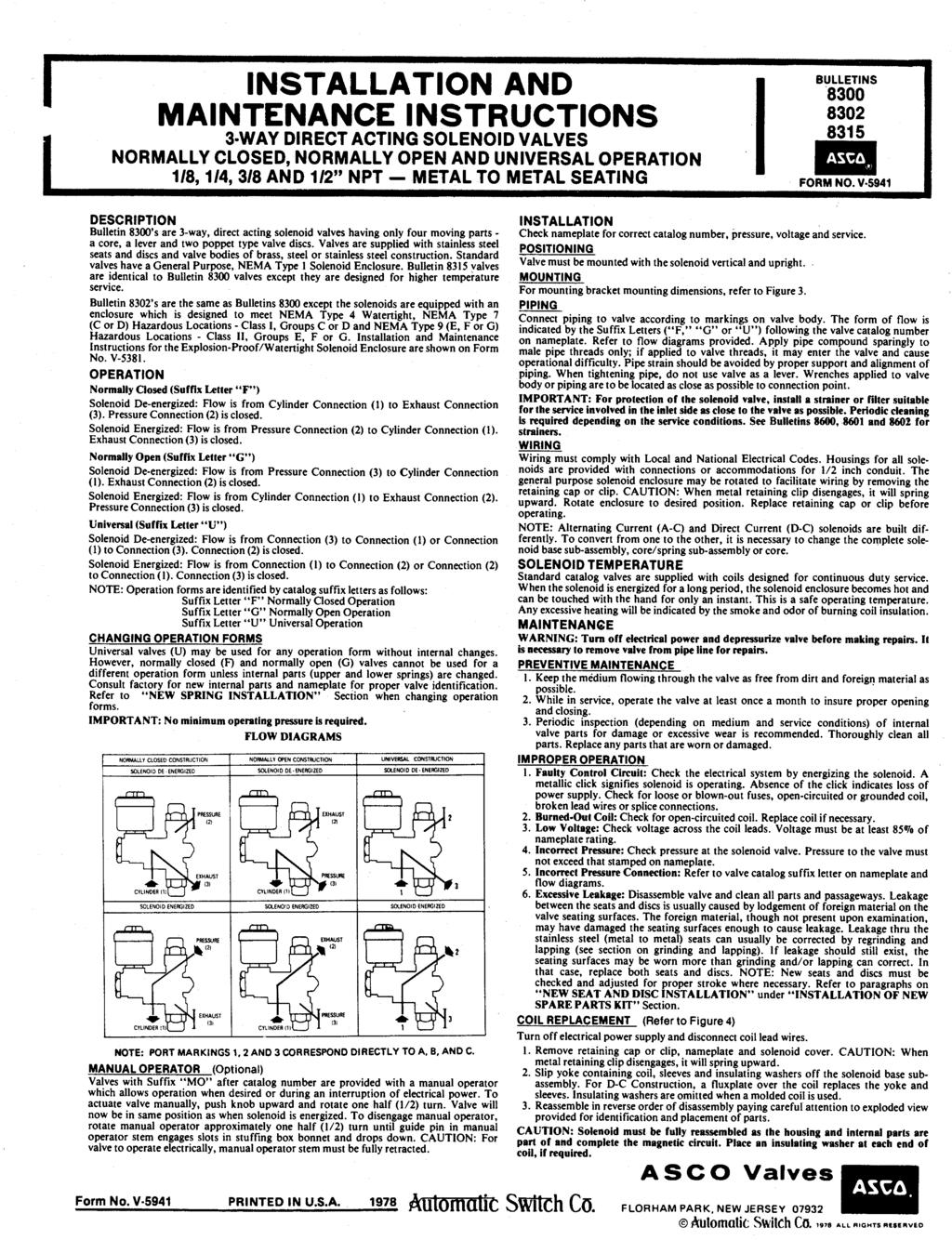
 I&M No.V9575R3 (Section1of2)") Installation & Maintenance Instructions -- WAY DIRECT-- ACTING SOLENOID VALVES REVISION H & R NORMALLY OPEN OR NORMALLY CLOSED OPERATION BRASS OR STAINLESS STEEL CONSTRUCTION -- 1/8I, 1/4I, OR3/8I PIPE
Installation & Maintenance Instructions -- WAY DIRECT-- ACTING SOLENOID VALVES REVISION H & R NORMALLY OPEN OR NORMALLY CLOSED OPERATION BRASS OR STAINLESS STEEL CONSTRUCTION -- 1/8I, 1/4I, OR3/8I PIPE
Parts List. Item # Part # # Reqd. Description
 5.2017.6.f 1 3800 Series Injector 1 2 3 4 5 6 7 21 8 9 20 10 11 12 19 18 17 16 15 14 13 Parts List Item # Part # # Reqd. Description 1 A-0664 1 5 Gallon 430 Reservoir 2 A-0575 1 Thumb Screw 3 A-0172 1
2006 Series Geared Rotary Limit Switches
 SUPERIOR DESIGN AND OPERATING FEATURES Quality parts make each Geared Rotary Limit Switch highly dependable. The limit switch s ½" input shaft is connected to a worm gear. Adjustable self-lubricating nylon
North American Automatic Manual Reset and Motorized Valves
 Combustion North American Automatic Manual Reset and Motorized Valves 1516 Manual Reset 1517 Motorized 1516/1517 Automatic Oil Shutoff Valves Agency approvals: UL, FM, CSA Proof-of-Closure Switch High
2/2 ^ % ) Pilot Operated General Service Solenoid Valves. Brass or Stainless Steel Bodies 3/8" to 2 1/2" NPT. Features. Construction.
 Pilot Operated General Service Solenoid Valves. Brass or Stainless Steel Bodies 3/8 to 2 1/2 NPT. Features. Construction.") 4 ilot Operated General Service Solenoid Valves Brass or Stainless Steel Bodies 3/8" to 2 1/2" 8210 2-AY Features ide range of pressure ratings, sizes, and resilient materials provide long service life
4 ilot Operated General Service Solenoid Valves Brass or Stainless Steel Bodies 3/8" to 2 1/2" 8210 2-AY Features ide range of pressure ratings, sizes, and resilient materials provide long service life
LEAD FREE * LFF113RFP Flood Protection Shut Down Valve
 Technical Bulletin TB-ACV-LFF11RFP LEAD FREE * LFF11RFP Flood Protection Shut Down Valve Installed upstream of Reduced Zone Backflow Preventer. Normally Open Valve - Closes when continuous discharge from
HIGH PRESSURE CONTROL VALVE PISTON BALANCED
 PISTON BALANCED All Rights Reserved. All contents of this publication including illustrations are believed to be reliable. And while efforts have been made to ensure their accuracy, they are not to be
I & M 8000 Series. Ideal Installation Schematic. Preferred Installation. Trouble Shooting
 I & M 8000 Series 3170 Wasson Road Cincinnati, OH 45209 USA Phone 513-533-5600 Fax 513-871-0105 lowflow@richardsind.com www.lowflowvalve.com Installation & Maintenance Instructions for 8000 Series Low
Electronic Control Valves
 MODEL 131 Series (Full Internal Port) 631 Series (Reduced Internal Port) Electronic Control Valves Model 131-01/631-01 Simple Proven Design Quality Solenoid Pilot Controls Ideal For SCADA Systems Multi-Function
Ideal Installation. I & M Mark 67 (1/2 6 ) Control Line. Installation & Maintenance Instructions for Mark 67 Pressure Regulators
 Control Line. Installation & Maintenance Instructions for Mark 67 Pressure Regulators") I & M Mark (/ ) 0 Wasson Road Cincinnati, OH 0 USA Phone --00 Fax -8-00 info@richardsind.com www.jordanvalve.com Installation & Maintenance Instructions for Mark Pressure Regulators Warning: Jordan Valve
I & M Mark (/ ) 0 Wasson Road Cincinnati, OH 0 USA Phone --00 Fax -8-00 info@richardsind.com www.jordanvalve.com Installation & Maintenance Instructions for Mark Pressure Regulators Warning: Jordan Valve
Environment-Sealed Basic Switches
 HoneywellSensing and Control 1-800-537-6945 USA 1-815-235-6847International 1-416-293-8111Canada 13 Environment-Sealed Basic Switches GENERAL INFORMATION SE and XE switches are the smallest environment-sealed
OPERATING INSTRUCTIONS & SERVICE MANUAL BLUE MAX II HYDROSTATIC TEST PUMP
 PAGE 1 OF 10 OPERATING INSTRUCTIONS & SERVICE MANUAL BLUE MAX II HYDROSTATIC TEST PUMP EFFICIENT, EASY OPERATION Air operated pump Wide range of pressures and volumes Easy to operate controls Output pressure
M&H AWWA C508 STANDARD SWING CHECK VALVES
 GENERAL M&H AWWA C508 STANDARD SWING CHECK VALVES Style 59-02 plain / 159-Lever & Weight / 259-02 Lever & Spring Sizes 2 Through 36 Water / Sewage Service M&H Swing Check valves are widely specified by
NECO Pumping Systems
 INSTALLATION OPERATION & MAINTENANCE INSTRUCTIONS For Your NECO Pumping Systems PACKAGED CIRCULATING SYSTEM THIS COMPLETELY ASSEMBLED, TESTED, PACKAGED CIRCULATING SYSTEM IS OF THE HIGHEST QUALITY AND
PRESSURE REDUCING CONTROL VALVES
 PROJECT NAME LOCATION PRESSURE REDUCING CONTROL VALVES INTRODUCTION This specification covers the design, manufacture, and testing of 1 in. (25 mm) through 36 in. (900 mm) Control Valves PART 1 - GENERAL
MC-351, 421, 431, MC-4311
 MC-35, 42, 43, MC-43 Three-Wire, Two Position Actuators General Instructions Applications For two-position operation of dampers or valves in heating, ventilating and air-conditioning systems and similar
FLOOD PROTECTION SHUT DOWN VALVE (3 and smaller)
") FLOOD PROTECTION SHUT DOWN VALVE ( and smaller) 01/10 2 6 To Floor Drain L X JB11 4 FS99 5 Installed upstream of Reduced Zone Backflow Preventer. Normally Open Valve - Closes when discharge from RPZ Relief
FLOOD PROTECTION SHUT DOWN VALVE ( and smaller) 01/10 2 6 To Floor Drain L X JB11 4 FS99 5 Installed upstream of Reduced Zone Backflow Preventer. Normally Open Valve - Closes when discharge from RPZ Relief
ALTITUDE CONTROL VALVES FOR ONE WAY FLOW
 PROJECT NAME LOCATION ALTITUDE CONTROL VALVES FOR ONE WAY FLOW INTRODUCTION This specification covers the design, manufacture, and testing of 2 in. (50 mm) through 36 in. (900 mm) Control Valves PART 1
SELF PRIMING CHEMICAL SERVICE PUMPS
 SELF PRIMING CHEMICAL SERVICE PUMPS INSTALLATION AND OPERATING INSTRUCTIONS This Manual covers: SELF PRIMING MODEL RANGE J50ECX TO J250ECX STAINLESS STEEL*, and NON METALLIC SEAL PUMP MODEL: SERIAL NO:
MODEL CMS INSTALLATION INSTRUCTIONS A. INTRODUCTION 1. USAGE 2 2. HOW IT OPERATES 2 B. SPECIFICATIONS 1. ELECTRICAL 3 2.
 CONVEYOR COMPONENTS COMPANY 130 Seltzer Road, PO Box 167 Croswell, MI 48422 USA PHONE: (810) 679-4211 TOLL FREE (800) 233-3233 FAX: (810) 679-4510 Email: info@conveyorcomponents.com http://www.conveyorcomponents.com
INSTALLATION & MAINTENANCE MODEL mm
 MODEL 65-25mm INSTALLATION INSTRUCTIONS CAUTION: Installation of Backflow Preventers must be performed by qualified, licensed personnel. The installer should be sure the proper device has been selected
MARFAID Solenoid Valves
 Series 125 2-Way Normally Closed Pilot Operated Diaphragm Type Bronze Construction Wide Variety of Voltages Maximum Temperature 190 F Pressure Range 5-150 psi Horizontal or Vertical Installation 1-15 4"
Instructions for Installation, Operation, Care and Maintenance
 Bulletin 59 Model DDX Deluge Valve (50 mm), ½ (65 mm), (80 mm), 76 mm, 4 (00 mm), 6 (50 mm), 65 mm & 8 (00 mm) Bulletin 59 Instructions for Installation, Operation, Care and Maintenance Wet Pilot Line,
DOROT CONTROL VALVES CATALOGUE
 DOROT CONTROL VALVES CATALOGUE Content SERIES 80 Globe & Angle Irrigation Valves 4 SERIES 80 80-1, 80-3/4 Turf Irrigation Valves 6 SERIES 75 Gal Plastic Valves 8 SERIES 95/96 UPVC Valves 10 Plastic Control
I & M Mark 78 Series. Ideal Installation. Start-Up. Installation & Maintenance Instructions for Mark 78 Control Valves (1-1/2-2 )
") I & M Mark 8 Series 0 Wasson Road Cincinnati, OH 4509 USA Phone 5-5-5600 Fax 5-8-005 info@richardsind.com www.jordanvalve.com Installation & Maintenance Instructions for Mark 8 Control Valves (-/ - ) Warning:
I & M Mark 8 Series 0 Wasson Road Cincinnati, OH 4509 USA Phone 5-5-5600 Fax 5-8-005 info@richardsind.com www.jordanvalve.com Installation & Maintenance Instructions for Mark 8 Control Valves (-/ - ) Warning:
Type N550 Snappy Joe Emergency Shutoff Valves
 Instruction Manual MCK-1149 Type N550 March 2010 Type N550 Snappy Joe Emergency Shutoff Valves Failure to follow these instructions or to properly install and maintain this equipment could result in an
3SE03 North American Limit Switches
 General Information Features Modular plug-in Prewired receptacle with pin connector Prewired cable Features UL Listed, CSA Certified. UL File: E47512 All Metal Captive Screws. Keyed, Four-Directional Head.
Installation Instructions
 Page 6300-S-1 Installation Instructions 1. Read complete instructions before proceeding and do not discard packing materials until any/all loose items are located. Also, make sure that the installation
3SE03 North American Limit Switches
 General Information Features Modular plug-in Prewired receptacle with pin connector Prewired cable Features UL Listed, CSA Certified. UL File: E47512 All Metal Captive Screws. Keyed, Four-Directional Head.
FLOAT CONTROL VALVES
 PROJECT NAME LOCATION FLOAT CONTROL VALVES INTRODUCTION This specification covers the design, manufacture, and testing of 8 in. (200 mm) through 36 in. (900 mm) Control Valves PART 1 - GENERAL 1. Standard
Booster Pump Control Valve
 MODEL 60-7 660-7 ooster Pump Control Valve Simple Hydraulic Operation Low Head Loss Horizontal or Vertical Mounting uilt-in Check Valve Proven Reliable Design The Cla-Val Model 60-7/660-7 ooster Pump Control
I & M Mark 78 Series. Ideal Installation. Start-Up. Installation & Maintenance Instructions for Mark 78 Control Valves (1/2-1 )
") I & M Mark 8 Series 30 Wasson Road Cincinnati, OH 4509 USA Phone 53-533-5600 Fax 53-8-005 info@richardsind.com www.jordanvalve.com Installation & Maintenance Instructions for Mark 8 Control Valves (/ -
I & M Mark 8 Series 30 Wasson Road Cincinnati, OH 4509 USA Phone 53-533-5600 Fax 53-8-005 info@richardsind.com www.jordanvalve.com Installation & Maintenance Instructions for Mark 8 Control Valves (/ -
MODEL RCW NON-INTERLOCK PREACTION SYSTEM
 GENERAL DESCRIPTION The Globe Model RCW non-interlock preaction valve is a hydraulically operated external resetting differential latching style valve designed for use where quickopening and total flooding
ACCESSORIES FOR AIR VALVES & AIR SYSTEMS
 ACCESSORIES FOR AIR VALVES & AIR SYSTEMS BULLETIN ACC-2000R AIR VALVES FOR INDUSTRY SINCE 1949 ISO 9001 CERTIFIED FOOT GUARDS Page 8 QUICK EXHAUST & ELECTRIC QUICK EXHAUST VALVES Pages 6 & 7 SHUTTLE VALVES
PRESSURE RELIEF / SUSTAINING CONTROL VALVES
 PROJECT NAME LOCATION PRESSURE RELIEF / SUSTAINING CONTROL VALVES INTRODUCTION This specification covers the design, manufacture, and testing of 1 in. (25 mm) through 36 in. (900 mm) Control Valves PART
User s Manual D-Series Blowers and Exhausters
 User s Manual D-Series Blowers and Exhausters D05-1 ½ HP TEFC 115/230 VOLTS, 1 PH D05-3 ½ HP TEFC 208/230/460 VOLTS, 3 PH D10-1 1 HP TEFC 115/230 VOLTS, 1 PH D10-3 1 HP TEFC 208/230/460 VOLTS, 3 PH D15-1
PRESSURE RELIEF / SURGE ANTICIPATOR CONTROL VALVE
 PROJECT NAME LOCATION PRESSURE RELIEF / SURGE ANTICIPATOR CONTROL VALVE INTRODUCTION This specification covers the design, manufacture, and testing of 2-1/2 in. (65 mm) through 18 in. (450 mm) Control
BERMAD Waterworks. Booster Pump Control Valve Active Check Valve. 700 Series. Model 740. Features and Benefits. Major Additional Features
 Booster Pump Control Valve Active Check Valve Isolates system from the effects of pump starts and stops for: Solitary single speed pumps Battery of single speed pumps (add & switch) Battery of variable
4 N E X T G E N E R A T I O N
 N X T G N R A T I O N lectronically nhanced Solenoid Valves and Stainless Steel Bodies /" - " NPT / 3/ / SRIS Next Generation Features Increase in DC pressure ratings to AC levels on all products (up to
Low Power. 1.4 W Low Power Solenoid Valves. Brass or Stainless Steel Bodies 1/4" to 1" NPT. Features
 .4 W Solenoid Valves Brass or Stainless Steel Bodies /4" to " NPT 4/ Features Moulded one-piece solenoid with highly efficient solenoid cartridge and special low wattage coil Designed for use in automation
High Pressure Solenoid Valves
 High Pressure Solenoid Valves Available for Quick Delivery Controls the flow of Gases & Liquids up to 15,000 PSIG Natural Gas, Hydrogen & other High Pressure Gases High Pressure Cryogenics Flammable Liquids
Double Acting & Spring Return. SERIES 92/93 Rack & Pinion PNEUMATIC ACTUATOR. The High Performance Company
 PNEUMATIC ACTUATOR SERIES 92/93 Rack & Pinion Double Acting & Spring Return The High Performance Company SERIES 92/93 Styling, strength, compactness, and simplicity of design have been combined to produce
VQ400M SERIES CLASS A COMBINATION VALVES PRODUCT HANDBOOK APPLICATION
 VQ400M SERIES PRODUCT HANDBOOK APPLICATION The VQ400M Series class A safety combination valves are used for control and regulation of gaseous fluids in gas power burners, atmospheric gas boilers, melting
D-Series Blowers and Exhausters
 Operation and Maintenance Manual D-Series MONOXIVENT - SOURCE CAPTURE SYSTEMS - info@ Oct. - 2015 MONOXVENT BLOWERS AND EXHAUSTERS D05-1 D05-3 D10-1 D10-3 D15-1 D15-3 D20-1 D20-3 D30-1 D30-3 ½ HP TEFC
PRESSURE RELIEF VALVE CONTROL VALVE
 PRESSURE RELIEF VALVE CONTROL VALVE LEHRY Pressure Relief Valve, Sustaining or Backpressure Control Valve is designed to permitting flow when upstream pressure is above the adjustable setpoint of the control
GH-BETTIS SERVICE INSTRUCTIONS DISASSEMBLY & REASSEMBLY FOR MODELS HD521-M4, HD721-M4 AND HD731-M4 DOUBLE ACTING SERIES PNEUMATIC ACTUATORS
 GH-BETTIS SERVICE INSTRUCTIONS DISASSEMBLY & REASSEMBLY FOR MODELS HD521-M4, HD721-M4 AND HD731-M4 DOUBLE ACTING SERIES PNEUMATIC ACTUATORS WITH HYDRAULIC CONTROL PACKAGE PART NUMBER: SE-023 REVISION: