NONRESIDENT TRAINING COURSE
|
|
|
- Shannon George
- 6 years ago
- Views:
Transcription


1 NONRESIDENT TRAINING COURSE February 1994 Basic Machines NAVEDTRA DISTRIBUTION STATEMENT A: Approved for public release; distribution is unlimited.
2 Although the words he, him, and his are used sparingly in this course to enhance communication, they are not intended to be gender driven or to affront or discriminate against anyone. DISTRIBUTION STATEMENT A: Approved for public release; distribution is unlimited.
3 CHAPTER 12 INTERNAL COMBUSTION ENGINE CHAPTER LEARNING OBJECTIVES Upon completion of this chapter, you should be able to do the following: l l l l l Explain the principles of a combustion engine. Explain the process of an engine cycle. State the classifications of engines. Discuss the construction of an engine. List the auxiliary assemblies of an engine. The automobile is a familiar object to all of us. The engine that moves it is one of the most fascinating and talked about of all the complex machines we use today. In this chapter we will explain briefly some of the operational principles and basic mechanisms of this machine. As you study its operation and construction, notice that it consists of many of the devices and basic mechanisms covered earlier in this book. COMBUSTION ENGINE We define an engine simply as a machine that converts heat energy to mechanical energy. The engine does this through either internal or external combustion. Combustion is the act of burning. Internal means inside or enclosed. Thus, in internal combustion engines, the burning of fuel takes place inside the engine; that is, burning takes place within the same cylinder that produces energy to turn the crankshaft. In external combustion engines, such as steam engines, the burning of fuel takes place outside the engine. Figure 12-1 shows, in the simplified form, an external and an internal combustion engine. The external combustion engine contains a boiler that holds water. Heat applied to the boiler causes the water to boil, which, in turn, produces steam. The steam passes into the engine cylinder under pressure and forces the piston to move downward. With the internal Figure Simple external and internal combustion engine. 12-1
4 Figure Cylinder, piston, connecting rod, and crankshaft for a one-cylinder engine. combustion engine, the combustion takes place inside the cylinder and is directly responsible for forcing the piston to move downward. The change of heat energy to mechanical energy by the engine is based on a fundamental law of physics. It states that gas will expand upon the application of heat. The law also states that the compression of gas will increase its temperature. If the gas is confined with no outlet for expansion, the application of heat will increase the pressure of the gas (as it does in an automotive cylinder). In an engine, this pressure acts against the head of a piston, causing it to move downward. As you know, the piston moves up and down in the cylinder. The up-and-down motion is known as reciprocating motion. This reciprocating motion (straight line motion) must change to rotary motion (turning motion) to turn the wheels of a vehicle. A crank and a connecting rod change this reciprocating motion to rotary motion. All internal combustion engines, whether gasoline or diesel, are basically the same. They all rely on three elements: air, fuel, and ignition. Fuel contains potential energy for operating the engine; air contains the oxygen necessary for combustion; and ignition starts combustion. All are fundamental, and the engine will not operate without any one of them. Any discussion of engines must be based on these three elements and the steps and mechanisms involved in delivering them to the combustion chamber at the proper time. DEVELOPMENT OF POWER The power of an internal combustion engine comes from the burning of a mixture of fuel and air in a small, enclosed space. When this mixture burns, it expands; the push or pressure created then moves the piston, thereby cranking the engine. This movement is sent back to the wheels to drive the vehicle. 12-2
5 Figure Relationship of piston, connecting rod, and crank on crankshaft as crankshaft turns one revolution. Since similar action occurs in all cylinders of an engine, we will describe the use one cylinder in the development of power. The one-cylinder engine consists of four basic parts: cylinder, piston, connecting rod, and crankshaft (shown in fig. 12-2). The cylinder, which is similar to a tall metal can, is closed at one end. Inside the cylinder is the piston, a movable metal plug that fits snugly into the cylinder, but can still slide up and down easily. This up-and-down movement, produced by the burning of fuel in the cylinder, results in the production of power from the engine. You have already learned that the up-and-down movement is called reciprocating motion. This motion must be changed to rotary motion to rotate the wheels or tracks of vehicles. This change is accomplished by a crank on the crankshaft and a connecting rod between the piston and the crank. The crankshaft is a shaft with an offset portion-the crank that describes a circle as the shaft rotates. The top end of the connecting rod connects to the piston and must therefore go up and down. Since the lower end of the connecting rod attaches to the crankshaft, it moves in a circle; however it also moves up and down. When the piston of the engine slides downward because of the pressure of the expanding gases in the cylinder, the upper end of the connecting rod moves downward with the piston in a straight line. The lower end of the connecting rod moves down and in a circular motion at the same time. This moves the crank; in turn, the crank rotates the shaft. This rotation is the desired result. So remember, the crankshaft and connecting rod combination is a mechanism for changing straight-line, up-and-down motion to circular, or rotary, motion. BASIC ENGINE STROKES Each movement of the piston from top to bottom or from bottom to top is called a stroke. The piston takes two strokes (an upstroke and a downstroke) as the crankshaft makes one complete revolution. When the piston is at the top of a stroke, it is said to be at top dead center. When the piston is at the bottom of a stroke, it is said to be at bottom dead center. These positions are rock positions, which we will discuss further in this chapter under Timing. See figure 12-3 and figure The basic engine you have studied so far has had no provisions for getting the fuel-air mixture into the cylinder or burned gases out of the cylinder. The 12-3
6 Figure Four-stroke cycle in a gasoline engine. 12-4
7 enclosed end of a cylinder has two openings. One of the openings, or ports, permits the mixture of air and fuel to enter, and the other port permits the burned gases to escape from the cylinder. The two ports have valves assembled in them. These valves, actuated by the camshaft, close off either one or the other of the ports, or both of them, during various stages of engine operation. One of the valves, called the intake valve, opens to admit a mixture of fuel and air into the cylinder. The other valve, called the exhaust valve, opens to allow the escape of burned gases after the fuel-and-air mixture has burned. Later you will learn more about how these valves and their mechanisms operate. The following paragraphs explain the sequence of actions that takes place within the engine cylinder: the intake stroke, the compression stroke, the power stroke, and the exhaust stroke. Since these strokes are easy to identify in the operation of a four-cycle engine, that engine is used in the description. This type of engine is called a four-stroke-otto-cycle engine, named after Dr. N. A. Otto who, in 1876, first applied the principle of this engine. INTAKE STROKE The first stroke in the sequence is the intake stroke (fig. 12-4). During this stroke, the piston is moving downward and the intake valve is open. This downward movement of the piston produces a partial vacuum in the cylinder, and air and fuel rush into the cylinder past the open intake valve. This action produces a result similar to that which occurs when you drink through a straw. You produce a partial vacuum in your mouth, and the liquid moves up through the straw to fill the vacuum. COMPRESSION STROKE When the piston reaches bottom dead center at the end of the intake stroke (and is therefore at the bottom of the cylinder) the intake valve closes and seals the upper end of the cylinder. As the crankshaft continues to rotate, it pushes the connecting rod up against the piston. The piston then moves upward and compresses the combustible mixture in the cylinder. This action is known as the compression stroke (fig. 12-4). In gasoline engines, the mixture is compressed to about one-eighth of its original volume. (In a diesel engine the mixture may be compressed to as little as one-sixteenth of its original volume.) This compression of the air-fuel mixture increases the pressure within the cylinder. Compressing the mixture in this way makes it more combustible; not only does the pressure in the cylinder go up, but the temperature of the mixture also increases. POWER STROKE As the piston reaches top dead center at the end of the compression stroke (and is therefore at the top of the cylinder), the ignition system produces an electric spark. The spark sets fire to the fuel-air mixture. In burning, the mixture gets very hot and expands in all directions. The pressure rises to about 600 to 700 pounds per square inch. Since the piston is the only part that can move, the force produced by the expanding gases forces the piston down. This force, or thrust, is carried through the connecting rod to the crankpin on the crankshaft. The crankshaft is given a powerful twist. This is known as the power stroke (fig. 12-4). This turning effort, rapidly repeated in the engine and carried through gears and shafts, will turn the wheels of a vehicle and cause it to move along the highway. EXHAUST STROKE After the fuel-air mixture has burned, it must be cleared from the cylinder. Therefore, the exhaust valve opens as the power stroke is finished and the piston starts back up on the exhaust stroke (fig. 12-4). The piston forces the burned gases of the cylinder past the open exhaust valve. The four strokes (intake, compression, power, and exhaust) are continuously repeated as the engine runs. ENGINE CYCLES Now, with the basic knowledge you have of the parts and the four strokes of the engine, let us see what happens during the actual running of the engine. To produce sustained power, an engine must repeatedly complete one series of the four strokes: intake, compression, power, and exhaust. One completion of this series of strokes is known as a cycle. Most engines of today operate on four-stroke cycles, although we use the term four-cycle engines to refer to them. The term actually refers to the four strokes of the piston, two up and two down, not the number of cycles completed. For the engine to operate, the piston continually repeats the four-stroke cycle. TWO-CYCLE ENGINE In the two-cycle engine, the entire series of strokes (intake, compression, power, and exhaust) takes place in two piston strokes. 12-5


8 Figure Events in a two-cycle, internal combustion engine. A two-cycle engine is shown in figure Every other stroke in this engine is a power stroke. Each time the piston moves down, it is on the power stroke. Intake, compression, power, and exhaust still take place; but they are completed in just two strokes. Figure 12-5 shows that the intake and exhaust ports are cut into the cylinder wall instead of at the top of the combustion chamber as in the four-cycle engine. As the piston moves down on its power stroke, it first uncovers the exhaust port to let burned gases escape and then uncovers the intake port to allow a new fuel-air mixture to enter the combustion chamber. Then on the upward stroke, the piston covers both ports and, at the same time, compresses the new mixture in preparation for ignition and another power stroke. In the engine shown in figure 12-5, the piston is shaped so that the incoming fuel-air mixture is directed upward, thereby sweeping out ahead of it the burned exhaust gases. Also, there is an inlet into the crankcase through which the fuel-air mixture passes before it enters the cylinder. This inlet is opened as the piston moves upward, but it is sealed as the piston moves downward on the power stroke. The downward moving piston slightly compresses the mixture in the crankcase. That gives the mixture enough pressure to pass rapidly through the intake port as the piston clears this port. This action improves the sweeping-out, or scavenging, effect of the mixture as it enters and clears the burned gases from the cylinder through the exhaust port. FOUR-CYCLE VERSUS TWO-CYCLE ENGINES You have probably noted that the two-cycle engine produces a power stroke every crankshaft revolution; the four-cycle engine requires two crankshaft revolutions for each power stroke. It might appear that the two-cycle engine could produce twice as much power as the four-cycle engine of the same size, operating at the same speed. However, that is not true. With the two-cycle engine, some of the power is used to drive the blower that forces the air-fuel charge into the cylinder under pressure. Also, the burned gases are not cleared from the cylinder. Additionally, because of the much shorter period the intake port is open (compared to the period the intake valve in a four-stroke-cycle is open), a smaller amount of fuel-air mixture is admitted. Hence, with less fuel-air mixture, less power per power stroke is produced compared to the power produced in a four-stroke cycle engine of like size operating at the same speed and under the same conditions. To increase the amount of fuel-air mixture, we use auxiliary devices with the two-stroke engine to ensure delivery of greater amounts of fuel-air mixture into the cylinder. 12-6
9 Figure Crankshaft for a six-cylinder engine. MULTIPLE-CYLINDER ENGINES The discussion so far in this chapter has concerned a single-cylinder engine. A single cylinder provides only one power impulse every two crankshaft revolutions in a four-cycle engine. It delivers power only one-fourth of the time. To provide for a more continuous flow of power, modem engines use four, six, eight, or more cylinders. The same series of cycles take place in each cylinder. In a four-stroke cycle, six-cylinder engine, for example, the cranks on the crankshaft are set 120 degrees apart. The cranks for cylinders 1 and 6, 2 and 5, and 3 and 4 are in line with each other (fig. 12-6). The cylinders fire or deliver the power strokes in the following order: Thus, the power strokes follow each other so closely that a continuous and even delivery of power goes to the crankshaft. the valves is determined by the camshaft; the position of the piston is determined by the crankshaft. Correct valve timing is obtained by providing the proper relationship between the camshaft and the crankshaft. When the piston is at top dead center, the crankshaft can move 15 to 20 without causing the piston to move up and down any noticeable distance. This is one of the two rock positions (fig. 12-7) of the piston. When the piston moves up on the exhaust stroke, considerable momentum is given to the exhaust gases as they pass out through the exhaust valve port. If the exhaust valve closes at top dead center, a small amount of the gases TIMING In a gasoline engine, the valves must open and close at the proper times with regard to piston position and stroke. In addition, the ignition system must produce the sparks at the proper time so that the power strokes can start. Both valve and ignition system action must be properly timed if good engine performance is to be obtained. Valve timing refers to the exact times in the engine cycle that the valves trap the mixture and then allow the burned gases to escape. The valves must open and close so that they are constantly in step with the piston movement of the cylinder they control. The position of Figure Rock position. 12-7
10 will be trapped and will dilute the incoming fuel-air mixture when the intake valves open. Since the piston has little downward movement while in the rock position, the exhaust valve can remain open during this period and thereby permit a more complete scavenging of the exhaust gases. Ignition timing refers to the timing of the sparks at the spark plug gap with relation to the piston position during the compression and power strokes. The ignition system is timed so that the sparks occurs before the piston reaches top dead center on the compression stroke. That gives the mixture enough time to ignite and start burning. If this time were not provided, that is, if the spark occurred at or after the piston reached top dead center, then the pressure increase would not keep pace with the piston movement. At higher speeds, there is still less time for the fuelair mixture to ignite and bum. To make up for this lack of time and thereby avoid power loss, the ignition system includes an advance mechanism that functions on speed. CLASSIFICATION OF ENGINES Engines for automotive and construction equipment may be classified in several ways: type of fuel used, type of cooling employed, or valve and cylinder arrangement. They all operate on the internal combustion principle. The application of basic principles of construction to particular needs or systems of manufacture has caused certain designs to be recognized as conventional. The most common method of classification is based on the type of fuel used; that is, whether the engine burns gasoline or diesel fuel. GASOLINE ENGINES DIESEL ENGINES VERSUS Mechanically and in overall appearance, gasoline and diesel engines resemble one another. However, many parts of the diesel engine are designed to be somewhat heavier and stronger to withstand the higher temperatures and pressures the engine generates. The engines differ also in the fuel used, in the method of introducing it into the cylinders, and in how the air-fuel mixture is ignited. In the gasoline engine, we first mix air and fuel in the carburetor. After this mixture is compressed in the cylinders, it is ignited by an electrical spark from the spark plugs. The source of the energy producing the electrical spark may be a storage battery or a high-tension magneto. The diesel engine has no carburetor. Air alone enters its cylinders, where it is compressed and reaches a high temperature because of compression. The heat of compression ignites the fuel injected into the cylinder and causes the fuel-air mixture to burn. The diesel engine needs no spark plugs; the very contact of the diesel fuel with the hot air in the cylinder causes ignition. In the gasoline engine the heat compression is not enough to ignite the air-fuel mixture; therefore, spark plugs are necessary. ARRANGEMENT OF CYLINDERS Engines are also classified according to the arrangement of the cylinders. One classification is the in-line, in which all cylinders are cast in a straight line above the crankshaft, as in most trucks. Another is the V-type, in which two banks of cylinders are mounted in a V shape above the crankshaft, as in many passenger vehicles. Another not-so-common arrangement is the horizontally opposed engine whose cylinders mount in two side rows, each opposite a central crankshaft. Buses often have this type of engine. The cylinders are numbered. The cylinder nearest the front of an in-line engine is numbered 1. The others are numbered 2, 3,4, and so forth, from the front to rear. In V-type engines the numbering sequence varies with the manufacturer. The firing order (which is different from the numbering order) of the cylinders is usually stamped on the cylinder block or on the manufacturer s nameplate. VALVE ARRANGEMENT The majority of internal combustion engines also are classified according to the position and arrangement of the intake and exhaust valves. This classification depends on whether the valves are in the cylinder block or in the cylinder head. Various arrangements have been used; the most common are the L-head, I-head, and F-head (fig. 12-8). The letter designation is used because the shape of the combustion chamber resembles the form of the letter identifying it. L-Head In the L-head engines, both valves are placed in the block on the same side of the cylinder. The valveoperating mechanism is located directly below the valves, and one camshaft actuates both the intake and exhaust valves. 12-8

11 construction and design. Because many kinds of engines are needed for many different jobs, engines are designed to have closely related cylinder sizes, valve arrangements, and so forth. As an example, the General Motors series 71 engines may have two, three, four, or six cylinders. However, they are designed so that the same pistons, connecting rods, bearings, valves and valve operating mechanisms can be used in all four engines. Engine construction, in this chapter, will be broken down into two categories: stationary parts and moving parts. I-Head Figure L-, I-, and F-valve arrangement. Engines using the I-head construction are called valve-in-head or overhead valve engines, because the valves mount in a cylinder head above the cylinder. This arrangement requires a tappet, a push rod, and a rocker arm above the cylinder to reverse the direction of the valve movement. Only one camshaft is required for both valves. Some overhead valve engines make use of an overhead camshaft. This arrangement eliminates the long linkage between the camshaft and the valve. F-Head In the F-head engine, the intake valves normally are located in the head, while the exhaust valves are located in the engine block. This arrangement combines, in effect, the L-head and the I-head valve arrangements. The valves in the head are actuated from the camshaft through tappets, push rods, and rocker arms (I-head arrangement), while the valves in the block are actuated directly from the camshaft by tappets (L-head arrangement). ENGINE CONSTRUCTION Basic engine construction varies little, regardless of the size and design of the engine. The intended use of an engine must be considered before the design and size can be determined. The temperature at which an engine will operate has a great deal to do with the metals used in its construction. The problem of obtaining service parts in the field categorization of engines servicing procedures and are simplified by the into families based on STATIONARY PARTS The stationary parts of an engine include the cylinder block, cylinders, cylinder head or heads, crankcase, and the exhaust and intake manifolds. These parts furnish the framework of the engine. All movable parts are attached to or fitted into this framework. Engine Cylinder Block The engine cylinder block is the basic frame of a liquid-cooled engine, whether it is the in-line, horizontally opposed, or V-type. The cylinder block and crankcase are often cast in one piece that is the heaviest single piece of metal in the engine. (See fig ) In small engines, where weight is an important consideration, the crankcase may be cast separately. In most large diesel engines, such as those used in power plants, the crankcase is cast separately and is attached to a heavy stationary engine base. In practically all automotive and construction equipment, the cylinder block and crankcase are cast in one piece. In this course we are concerned primarily with liquid-cooled engines of this type. The cylinders of a liquid-cooled engine are surrounded by jackets through which the cooling liquid circulates. These jackets are cast integrally with the cylinder block. Communicating passages permit the coolant to circulate around the cylinders and through the head. The air-cooled engine cylinder differs from that of a liquid-cooled engine in that the cylinders are made individually, rather than cast in block. The cylinders of air-cooled engines have closely spaced fins surrounding the barrel; these fins provide an increased surface area from which heat can be dissipated. This engine design is in contrast to that of the liquid-cooled engine, which has a water jacket around its cylinders. 12-9
12 12-10

 made of metal alloys resistant to wear are used in many gasoline engines and practically all diesel engines to lessen wear.")


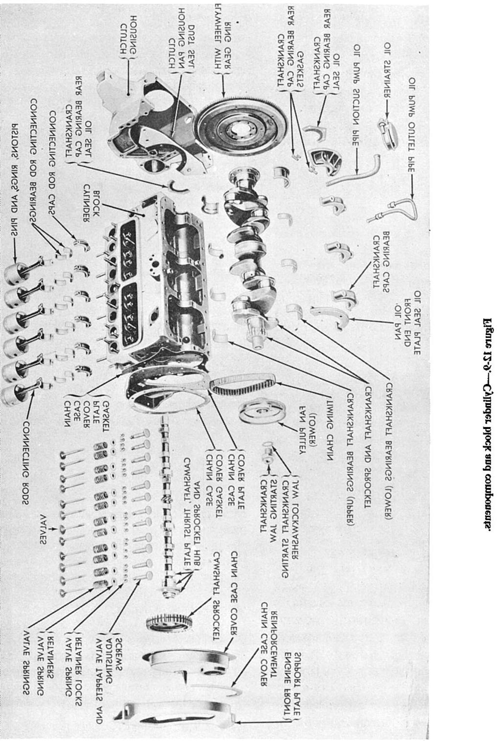
13 Cylinder Block Construction The cylinder block is cast from gray iron or iron alloyed with other metals such as nickel, chromium, or molybdenum. Some lightweight engine blocks are made from aluminum. Cylinders are machined by grinding or boring to give them the desired true inner surface. During normal engine operation, cylinder walls will wear out-of-round, or they may become cracked and scored if not properly lubricated or cooled. Liners (sleeves) made of metal alloys resistant to wear are used in many gasoline engines and practically all diesel engines to lessen wear. After they have been worn beyond the maximum oversize, the liners can be replaced individually, which permits the use of standard pistons and rings. Thus, you can avoid replacing the entire cylinder block The liners are inserted into a hole in the block with either a PRESS FIT or a SLIP FIT. Liners are further designated as either a WET-TYPE or DRY-TYPE. The wet-type liner comes in direct contact with the coolant and is sealed at the top by a metallic sealing ring and at the bottom by a rubber sealing ring. The dry-type liner does not contact the coolant. Engine blocks for L-head engines contain the passageways for the valves and valve ports. The lower part of the block (crankcase) supports the crankshaft (the main bearings and bearing caps) and provides a place to which the oil pan can be fastened. The camshaft is supported in the cylinder block by bushings that fit into machined holes in the block. On L-head in-line engines, the intake and exhaust manifolds are attached to the side of the cylinder block. On L-head V-8 engines, the intake manifold is located between the two banks of cylinders; these engines have two exhaust manifolds, one on the outside of each bank. Cylinder Head The cylinder head provides the combustion chambers for the engine cylinders. It is built to conform to the arrangement of the valves: L-head, I-head, or other. In the water-cooled engine, the cylinder head (fig ) is bolted to the top of the cylinder block to close the upper end of the cylinders. It contains passages, Figure Cylinder head for L-head engine

14 Figure Intake and exhaust manifolds. matching those of the cylinder block, that allow the cooling water to circulate in the head. The head also helps keep compression in the cylinders. The gasoline engine contains tapped holes in the cylinder head that lead into the combustion chamber. The spark plugs are inserted into these tapped holes. In the diesel engine the cylinder head may be cast in a single unit, or it may be cast for a single cylinder or two or more cylinders. Separated head sections (usually covering one, two, or three cylinders in large engines) are easy to handle and can be removed. The L-head type of cylinder head shown in figure is a comparatively simple casting. It contains water jackets for cooling, openings for spark plugs, and pockets into which the valves operate. Each pocket serves as a part of the combustion chamber. The fuel-air mixture is compressed in the pocket as the piston reaches the end of the compression stroke. Note that the pockets have a rather complex curved surface. This shape has been carefully designed so that the fuel-air mixture, compressed, will be subjected to violent turbulence. This turbulence ensures uniform mixing of the fuel and air, thus improving the combustion process. The I-head (overhead-valve) type of cylinder head contains not only valve and combustion chamber pockets and water jackets for cooling spark-plug openings, but it also contains and supports the valves and valve-operating mechanisms. In this type of cylinder head, the water jackets must be large enough to cool not only the top of the combustion chamber but also the valve seats, valves, and valve-operating mechanisms. Crankcase The crankcase is that part of the engine block below the cylinders. It supports and encloses the crankshaft and provides a reservoir for the lubricating oil. Often times the crankcase contains a place for mounting the oil pump, oil filter, starting motor, and generator. The lower part of the crankcase is the OIL PAN, which is bolted at the bottom. The oil pan is made of pressed or cast steel and holds from 4 to 9 quarts of oil, depending on the engine design. The crankcase also has mounting brackets that support the entire engine on the vehicle frame. These brackets are either an integral part of the crankcase or 12-12
15 are bolted to it so that they support the engine at three or four points. These points of contact usually are cushioned with rubber that insulates the frame and the body of the vehicle from engine vibration and therefore prevents damage to the engine supports and the transmission. Exhaust Manifold The exhaust manifold is a tube that carries waste products of combustion from the cylinders. On L-head engines the exhaust manifold is bolted to the side of the engine block on; overhead-valve engines it is bolted to the side of the engine cylinder head. Exhaust manifolds may be single iron castings or may be cast in sections. They have a smooth interior surface with no abrupt change in size (see fig ). Intake Manifold The intake manifold on a gasoline engine carries the fuel-air mixture from the carburetor and distributes it as evenly as possible to the cylinders. On a diesel engine, the manifold carries only air to the cylinders. The intake manifold is attached to the block on L-head engines and to the side of the cylinder head on overhead-valve engines. (See fig ) In gasoline engines, smooth and efficient engine performance depends largely on whether the fuel-air mixtures that enter each cylinder are uniform in strength, quality, and degree of vaporization. The inside walls of the manifold must be smooth to offer little obstruction to the flow of the fuel-air mixture. The manifold is designed to prevent the collecting of fuel at the bends in the manifold. The intake manifold should be as short and straight as possible to reduce the chances of condensation between the carburetor and cylinders. Some intake manifolds are designed so that hot exhaust gases heat their surfaces to help vaporize the fuel. Gaskets The principal stationary parts of an engine have just been explained. The gaskets (fig ) that serve as seals between these parts require as much attention during engine assembly as any other part. It is impractical to machine all surfaces so that they fit together to form a perfect seal. The gaskets make a joint that is air, water, or oil tight. Therefore, when properly Figure Engine overhaul gasket kit. installed, they prevent loss of compression, coolant, or lubricant. MOVING PARTS OF AN ENGINE The moving parts of an engine serve an important function in turning heat energy into mechanical energy. They further convert reciprocal motion into rotary motion. The principal moving parts are the piston assembly, connecting rods, crankshaft assembly (includes flywheel and vibration dampener), camshaft, valves, and gear train. The burning of the fuel-air mixture within the cylinder exerts a pressure on the piston, thus pushing it down in the cylinder. The action of the connecting rod and crankshaft converts this downward motion to a rotary motion. Piston Assembly Engine pistons serve several purposes. They transmit the force of combustion to the crankshaft through the connecting rod. They act as a guide for the upper end of the connecting rod. And they also serve as 12-13


16 in weight. To overcome inertia and momentum at high speed, it must be carefully balanced and weighed. All the pistons used in any one engine must be of similar weight to avoid excessive vibration. Ribs are used on the underside of the piston to reinforce the hand. The ribs also help to conduct heat from the head of the piston to the piston rings and out through the cylinder walls. The structural components of the piston are the head, skirt, ring grooves, and land (fig ). However, all pistons do not look like the typical one illustrated here. Some have differently shaped heads. Diesel engine pistons usually have more ring grooves and rings than gasoline engine pistons. Some of these rings may be installed below as well as above the wrist or piston pin (fig ). Figure Piston and connecting rod (exploded view). a carrier for the piston rings used to seal the compression in the cylinder. (See. fig ) The piston must come to a complete stop at the end of each stroke before reversing its course in the cylinder. To withstand this rugged treatment and wear, it must be made of tough material, yet be light Fitting pistons properly is important. Because metal expands when heated and space must be provided for lubricants between the pistons and the cylinder walls, the pistons are fitted to the engine with a specified clearance. This clearance depends upon the size or diameter of the piston and the material form which it is made. Cast iron does not expand as fast or as much as aluminum. Aluminum pistons require more clearance to prevent binding or seizing when the engine gets hot. The skirt of bottom part of the piston runs much cooler than the top; therefore, it does not require as much clearance as the head. Figure The parts of a piston
 (fig.12-16).")

17 Figure Piston assembly. Figure Cam-ground piston. The piston is kept in alignment by the skirt, which is usually cam ground (elliptical in cross section) (fig.12-16). This elliptical shape permits the piston to fit the cylinder, regardless of whether the piston is cold or at operating temperature. The narrowest diameter of the piston is at the piston pin bosses, where the piston skirt is thickest. At the widest diameter of the piston, the piston skirt is thinnest. The piston is fitted to close limits at its widest diameter so that the piston noise (slap) is prevented during the engine warm-up. As the piston is 12-15
18 Figure Piston pin types. expanded by the heat generated during operation, it becomes round because the expansion is proportional to the temperature of the metal. The walls of the skirt are cut away as much as possible to reduce weight and to prevent excessive expansion during engine operation. Many aluminum pistons are made with split skirts so that when the pistons expand, the skirt diameter will not increase. The two types of piston skirts found in most engines are the full trunk and the slipper. The full-trunk-type skirt, more widely used, has a full cylindrical shape with bearing surfaces parallel to those of the cylinder, giving more strength and better control of the oil film. The slipper-type (cutaway) skirt has considerable relief on the sides of the skirt, leaving less area for possible contact with the cylinder walls and thereby reducing friction. PISTON PINS. The piston is attached to the connecting rod by the piston pin (wrist pin). The pin passes through the piston pin bosses and through the upper end of the connecting rod, which rides within the piston on the middle of the pin. Piston pins are made of alloy steel with a precision finish and are case hardened and sometimes chromium plated to increase their wearing qualities. Their tubular construction gives them maximum strength with minimum weight. They are lubricated by splash from the crankcase or by pressure through passages bored in the connecting rods. Three methods are commonly used for fastening a piston pin to the piston and the connecting rod: fixed pin, semifloating pin, and full-floating pin (fig ). The anchored, or fixed, pin attaches to the piston by a screw running through one of the bosses; the connecting rod oscillates on the pin. The semifloating pin is anchored to the connecting rod and turns in the piston pin bosses. The full-floating pin is free to rotate in the connecting rod and in the bosses, while plugs or snap-ring locks prevent it from working out against the sides of the cylinder. PISTON RINGS. Piston rings are used on pistons to maintain gastight seals between the pistons and cylinders, to aid in cooling the piston, and to control cylinder-wall lubrication. About one-third of the heat absorbed by the piston passes through the rings to the cylinder wall. Piston rings are often complicated in design, are heat treated in various ways, and are plated with other metals. Piston rings are of two distinct classifications: compression rings and oil control rings. (See fig ) The principal function of a compression ring is to prevent gases from leaking by the piston during the compression and power strokes. All piston rings are split to permit assembly to the piston and to allow for expansion. When the ring is in place, the ends of the split joint do not form a perfect seal; therefore, more than one ring must be used, and the joints must be staggered around the piston. If cylinders are worn, expanders (figs and 12-18) are sometimes used to ensure a perfect seal. The bottom ring, usually located just above the piston pin, is an oil-regulating ring. This ring scrapes the excess oil from the cylinder walls and returns some of it, through slots, to the piston ring grooves. The ring groove under an oil ring has openings through which the oil flows back into the crankcase. In some engines, additional oil rings are used in the piston skirt below the piston pin


19 Figure Crankshaft of a four-cylinder engine. Connecting Rods Figure Piston rings. Connecting rods must be light and yet strong enough to transmit the thrust of the pistons to the crankshaft. Connecting rods are drop forged from a steel alloy capable of withstanding heavy loads without bending or twisting. Holes at the upper and lower ends are machined to permit accurate fitting of bearings. These holes must be parallel. The upper end of the connecting rod is connected to the piston by the piston pin. If the piston pin is locked in the piston pin bosses or if it floats in both the piston and the connecting rod, the upper hold of the connecting rod will have a solid bearing (bushing) of bronze or similar material. As the lower end of the connecting rod revolves with the crankshaft, the upper end is forced to turn back and forth on the piston pin. Although this movement is slight, the bushing is necessary because of the high pressure and temperatures. If the piston pin is semifloating, a bushing is not needed. The lower hole in the connecting rod is split to permit it to be clamped around the crankshaft. The bottom part, or cap, is made of the same material as the rod and is attached by two or more bolts. The surface that bears on the crankshaft is generally a bearing material in the form of a separate split shell; in a few cases, it may be spun or die-cast in the inside of the rod and cap during manufacture. The two parts of the separate bearing are positioned in the rod and cap by dowel pins, projections, or short brass screws. Split bearings may be of the precision or semiprecision type. The precision type bearing is accurately finished to fit the crankpin and does not require further fitting during installation. It is positioned by projections on the shell that match reliefs in the rod and cap. The projections prevent the bearings from moving sideways and prevent rotary motion in the rod and cap. The semiprecision-type bearing is usually fastened to or die-cast with the rod and cap. Before installation, it is machined and fitted to the proper inside diameter with the cap and rod bolted together. Crankshaft As the pistons collectively might be regarded as the heart of the engine, so the crankshaft might be considered the backbone (fig ). It ties together the reactions of the pistons and the connecting rods, transforming their reciprocating motion into rotary motion. It transmits engine power through the flywheel, clutch, transmission, and differential to drive your vehicle. The crankshaft is forged or cast from an alloy of steel and nickel. It is machined smooth to provide 12-17
20 Figure Crankshaft and throw arrangements commonly used. bearing surfaces for the connecting rods and the main bearings. It is case-hardened (coated in a furnace with copper alloyed and carbon). These bearing surfaces are called journals. The crankshaft counterweights impede the centrifugal force of the connecting rod and assembly attached to the throws or points of bearing support. These throws must be placed so that they counterbalance each other. Crankshaft and throw arrangements for four-, six-, and eight-cylinder engines are shown in figure Four-cylinder engine crankshafts have either three or five main support bearings and four throws in one plane. As shown in the figure, the four throws for the number 1 and 4 cylinders (four-cylinder engine) are 180 from those for the number 2 and 3 cylinders. On six-cylinder engine crankshafts, each of the three pairs of throws is arranged 120 from the other two. Such crankshafts may be supported by as many as seven main bearings one at each end of the shaft and one between each pair of crankshaft throws. The crankshafts of eight-cylinder V-type engines are similar to those of the four-cylinder in-line type. They may have each of the four throws fixed at 90 from each other (as in fig ) for better balance and smoother operation. V-type engines usually have two connecting rods fastened side by side on one crankshaft throw. With this arrangement, one bank of the engine cylinders is set slightly ahead of the other to allow the two rods to clear each other. Vibration Damper The power impulses of an engine result in torsional vibration in the crankshaft. A vibration damper mounted on the front of the crankshaft controls this vibration (fig ). If this torsional vibration were not controlled, the crankshaft might actually break at certain speeds. Most types of vibration dampers resemble a miniature clutch. A friction facing is mounted between the hub face and a small damper flywheel. The damper flywheel is mounted on the hub face with bolts that go through rubber cones in the flywheel. These cones permit limited circumferential movement between the crankshaft and damper flywheel. That reduces the effects of the torsional vibration in the crankshaft. Several other types of vibration dampers are used; however, they all operate in essentially the same way. 2-18

21 Figure Sectional view of a typical vibration damper. Engine Flywheel The flywheel mounts at the rear of the crankshaft near the rear main bearing. This is usually the longest and heaviest main bearing in the engine, as it must support the weight of the flywheel. The flywheel (fig ) stores up rotation energy during the power impulses of the engine. It releases this energy between power impulses, thus assuring less fluctuation in engine speed and smoother engine operation. The size of the flywheel will vary with the number of cylinders and the general construction of the engine. With the large number of cylinders and the consequent overlapping of power impulses, there is less need for a flywheel; consequently, the flywheel can be relatively small. The flywheel rim carries a ring gear, either integral with or shrunk on the flywheel, that meshes with the starter driving gear for cranking the engine. The rear face of the flywheel is usually machined and ground and acts as one of the pressure surfaces for the clutch, becoming a part of the clutch assembly. Figure Camshaft and bushings. Valves and Valve Mechanisms Most engines have two valves for each cylinder, one intake and one exhaust valve. Since each of these valves operates at different times, separate operating mechanisms must be provided for each valve. Valves are normally held closed by heavy springs and by compression in the combustion chamber. The purpose of the valve-actuating mechanism is to overcome the spring pressure and open the valves at the proper time. The valve-actuating mechanism includes the engine camshaft, camshaft followers (tappets), pushrods, and rocker arms. CAMSHAFT. The camshaft (fig ) is enclosed in the engine block. It has eccentric lobes (cams) ground on it for each valve in the engine. As the 12-19


22 Figure L-head valve operating mechanism. camshaft rotates, the cam lobe moves up under the valve tappet, exerting an upward thrust through the tappet against the valve stem or a pushrod. This thrust overcomes the valve spring pressure as well as the gas pressure in the cylinder, causing the valve to open. When the lobe moves from under the tappet, the valve spring pressure reseats the valve. On L-, F-, or I-head engines, the camshaft is usually located to one side and above the crankshaft; in V-type engines, it is usually located directly above the crankshaft. On the overhead camshaft engine, such as the Murphy diesel, the camshaft is located above the cylinder head. The camshaft of a four-stroke cycle engine turns at one-half engine speed. It is driven off the crankshaft through timing gears or a timing chain. In the two-stroke cycle engine, the camshaft must turn at the same speed as the crankshaft so that each valve may open and close once in each revolution of the engine. In most cases the camshaft will do more than operate the valve mechanism. It may have extra cams or gears that operate fuel pumps, fuel injectors, the ignition distributor, or the lubrication pump. Camshafts are supported in the engine block by journals in bearings. Camshaft bearing journals are the hugest machined surfaces on the shaft. The bearings are usually made of bronze and are bushings rather than split bearings. The bushings are lubricated by oil circulating through drilled passages from the crankcase. The stresses on the camshaft are small; therefore, the bushings are not adjustable and require little attention. The camshaft bushings are replaced only when the engine requires a complete overhaul. FOLLOWERS. Camshaft followers are the parts of the valve-actuating mechanism (figs and 12-25) that contact the camshaft. You will probably hear them called valve tappets or vale lifters. In the L-head engine, the followers directly contact the end of the valve stem and have an adjusting device in them. In the overhead valve engine, the followers contact the pushrod that operates the rocker arm. The end of the rocker arm opposite the pushrod contacts the valve stem. The valve adjusting device, in this case, is in the rocker arm. Many engines have self-adjusting, hydraulic valve lifters that always operate at zero clearance

23 Figure Valve operating mechanism for an overhead valve engine
24 Figure Operation of a hydraulic valve lifter. Figure shows the operation of one type of hydraulic valve tappet mechanism. Oil under pressure is forced into the tappet when the valve is closed. This pressure extends the plunger in the tappet so that all valve clearance, or lash, is eliminated. When the cam lobe moves around under the tappet and starts to raise it, you hear no tappet noise. The movement of the tappet forces the oil upward in the lower chamber of the tappet. This action closes the ball check valve so that oil cannot escape. Then the tappet acts as though it were a simple, one-piece tappet and the valve is opened. When the lobe moves out from under the tappet and the valve closes, the pressure in the lower chamber of the tappet is relieved. Any slight loss of oil from the lower chamber is replaced by the oil pressure from the engine lubricating system. This oil pressure causes the plunger to move up snugly against the push rod so that any clearance is eliminated. other a mark on only one tooth. Timing the valves properly requires that the gears mesh so that the two marked teeth of one gear straddle the single marked tooth of the other. AUXILIARY ASSEMBLIES We have discussed the main parts of the engine proper; but other parts, both moving and stationary, are essential to engine operation. They are not built into the engine itself, but usually are attached to the engine block or cylinder head. The fuel system includes a fuel pump and carburetor mounted on the engine. In diesel engines the fuel injection mechanism replaces the carburetor. An Timing Gears (Gear Trains) Timing gears keep the crankshaft and camshaft turning in proper relation to one another so that the valves open and close at the proper time. Some engines use sprockets and chains. The gears or sprockets, as the case may be, of the camshaft and crankshaft are keyed into position so that they cannot slip. Since they are keyed to their respective shafts, they can be replaced if they become worn or noisy. With directly driven timing gears (fig ), one gear usually has a mark on two adjacent teeth and the Figure Timing gears and their markings
25 electrical system is provided to supply power for starting the engine and for igniting it during operation. The operation of an internal combustion engine requires an efficient cooling system. Water-cooled engines use a water pump and fan while air-cooled engines use a blower to force cool air around the engine cylinders. In addition, an exhaust system is provided to carry away the burned gases exhausted from the engine cylinders. These systems will not be discussed in this course, however. For further information, refer to NAVPERS 10644G-1, Construction Mechanic 3 & 2. SUMMARY This chapter explained briefly the following operational principles and basic mechanisms of the internal combustion engine: The power of an internal combustion engine comes from the burning of a mixture of fuel and air in a small, enclosed space. The movement of the piston from top to bottom is called a stroke. To produce sustained power, an engine must repeatedly accomplish a definite series of operations. This series of events is called a cycle. Engine classifications are based on the type of fuel used gasoline or diesel. Design and size must be considered before engine construction. Engines require the use of auxiliary assemblies such as the fuel pump, the carburetor, and an electrical system
Handout Activity: HA170
 Basic diesel engine components Handout Activity: HA170 HA170-2 Basic diesel engine components Diesel engine parts are usually heavier or more rugged than those of similar output gasoline engines. Their
ENGINE & WORKING PRINCIPLES
 ENGINE & WORKING PRINCIPLES A heat engine is a machine, which converts heat energy into mechanical energy. The combustion of fuel such as coal, petrol, diesel generates heat. This heat is supplied to a
ENGINES ENGINE OPERATION
 ENGINES ENGINE OPERATION Because the most widely used piston engine is the four-stroke cycle type, it will be used as the example for this section, Engine Operation and as the basis for comparison in the
Diesel Engine Fundamentals Part 1 Course# ME4061
 Diesel Engine Fundamentals Part 1 Course# ME4061 EZpdh.com All Rights Reserved Diesel Engine Fundamentals DOE-HDBK-1018/1-93 TABLE OF CONTENTS TABLE OF CONTENTS LIST OF FIGURES... ii LIST OF TABLES...
UNIT IV INTERNAL COMBUSTION ENGINES
 UNIT IV INTERNAL COMBUSTION ENGINES Objectives After the completion of this chapter, Students 1. To know the different parts of IC engines and their functions. 2. To understand the working principle of
Modern Auto Tech Study Guide Chapter 11 Pages Engine Fundamentals 62 Points
 Modern Auto Tech Study Guide Chapter 11 Pages 145-161 Engine Fundamentals 62 Points 1. The is the area between the top of the piston & the cylinder head. Combustion Chamber Cylinder Chamber Chamber of
FUNDAMENTAL OF AUTOMOBILE SYSTEMS
 Prof. Kunalsinh Mechanical Engineering Dept. FUNDAMENTAL OF AUTOMOBILE SYSTEMS Prof. Kunalsinh kathia [MECHANICAL DEPT.] UNIT-2 [ENGINES] PART-1 Prof. Kunalsinh kathia [MECHANICAL DEPT.] Internal combustion
Internal Combustion Engines
 Internal Combustion Engines The internal combustion engine is an engine in which the burning of a fuel occurs in a confined space called a combustion chamber. This exothermic reaction of a fuel with an
Internal combustion engines can be classified in a number of different ways: 1. Types of Ignition
 Chapter 1 Introduction 1-3 ENGINE CLASSIFICATIONS Internal combustion engines can be classified in a number of different ways: 1. Types of Ignition 1 (a) Spark Ignition (SI). An SI engine starts the combustion
A. Aluminum alloy Aluminum that has other metals mixed with it.
 ENGINE REPAIR UNIT 1: ENGINE DESIGN LESSON 1: PRINCIPLES OF ENGINE DESIGN I. Terms and definitions A. Aluminum alloy Aluminum that has other metals mixed with it. B. Bearing A device that allows movement
SNS COLLEGE OF TECHNOLOGY (An Autonomous Institution) Department of Automobile Engineering
 Department of Automobile Engineering") SNS COLLEGE OF TECHNOLOGY (An Autonomous Institution) Department of Automobile Engineering ACADEMIC YEAR 2015-16 FIFTH SEMESTER AU 302 AUTOMOTIVE ENGINE COMPONENTS DESIGN UNIT 2 CYLINDER, PISTON & CONNECTING
SNS COLLEGE OF TECHNOLOGY (An Autonomous Institution) Department of Automobile Engineering ACADEMIC YEAR 2015-16 FIFTH SEMESTER AU 302 AUTOMOTIVE ENGINE COMPONENTS DESIGN UNIT 2 CYLINDER, PISTON & CONNECTING
Engine Construction and Principles of Operation
 Ch. 4 Engine Construction and Principles of Operation Gasoline Engine A gasoline fueled engine is a mechanism designed to transform chemical energy into mechanical energy It is an internal combustion engine.
THE WOLSELEY "VIPER" AERO ENGINE. (Hispano-Suiza W.4.A*)
") 13 THE WOLSELEY "VIPER" AERO ENGINE. (Hispano-Suiza W.4.A*) General description. The engine referred to in this article is the Hispano-Suiza 180 hp W.4.A* Aero Engine, as made by Wolseley Motors Ltd. The
13 THE WOLSELEY "VIPER" AERO ENGINE. (Hispano-Suiza W.4.A*) General description. The engine referred to in this article is the Hispano-Suiza 180 hp W.4.A* Aero Engine, as made by Wolseley Motors Ltd. The
Internal Combustion Engine
 Internal Combustion Engine The development of the internal combustion engine was made possible by the earlier development of the STEAM ENGINE. Both types of engines burn fuel, releasing energy from it
Automobile section, showing different parts in detail. and miscellaneous devices.
 SECTION VII Nos. 97 112 Automobile section, showing different parts in detail. and miscellaneous devices. Hydraulic jack MECHANICAL MODELS 43 Section VII 97. Automobile engine starter. This device known
CHECK OUT OUR WEBSITE SOME TIME FOR PLENTY OF ARTICES ABOUT SELF DEFENSE, SURVIVAL, FIREARMS AND MILITARY MANUALS.
 CHECK OUT OUR WEBSITE SOME TIME FOR PLENTY OF ARTICES ABOUT SELF DEFENSE, SURVIVAL, FIREARMS AND MILITARY MANUALS. http://www.survivalebooks.com/ Thank you for purchasing our ebook package. US ARMY LIGHT
CONVENTIONAL ENGINE CONSTRUCTION
 CONVENTIONAL ENGINE CONSTRUCTION CYLINDER BLOCKS, HEADS, AND CRANKCASES The cylinder, or the engine block, is the basic foundation of virtually all liquid-cooled engines. The block is a solid casting made
SAMPLE STUDY MATERIAL
 IC Engine - ME GATE, IES, PSU 1 SAMPLE STUDY MATERIAL Mechanical Engineering ME Postal Correspondence Course Internal Combustion Engine GATE, IES & PSUs IC Engine - ME GATE, IES, PSU 2 C O N T E N T 1.
Engine Design Classifications
 Chapter 12 Engine Design Classifications Name: Date: Instructor: Score: Textbook pages 158-175 Objective: After studying this chapter, you will be able to describe and explain basic automotive engine designs
MECHANICAL SCIENCE Module 1 Diesel Engine Fundamentals
 Department of Energy Fundamentals Handbook MECHANICAL SCIENCE Module 1 Diesel Engine Fundamentals Diesel Engine Fundamentals DOE-HDBK-1018/1-93 TABLE OF CONTENTS TABLE OF CONTENTS LIST OF FIGURES... ii
ENGINE MECHANICAL <134>
 11A-1 GROUP 11A ENGINE MECHANICAL CONTENTS GENERAL INFORMATION........ 11A-2.................. 11A-3 11A-2 The newly developed 1.1L 134910 engine features 3-cylinder, 12-valve, and double overhead
Bronze Level Training
 Bronze Level Training Engine Principles of Operation While not everyone at the dealership needs to be a top rated service technician, it is good for all the employees to have a basic understanding of engine
Comparative Study Of Four Stroke Diesel And Petrol Engine.
 Comparative Study Of Four Stroke Diesel And Petrol Engine. Aim: To study the construction and working of 4- stroke petrol / diesel engine. Theory: A machine or device which derives heat from the combustion
California State University, Bakersfield. Signals and Systems. Kristin Koehler. California State University, Bakersfield Lecture 4 July 18 th, 2013
 Kristin Koehler California State University, Bakersfield Lecture 4 July 18 th, 2013 1 Outline Internal combustion engines 2 stroke combustion engines 4 stroke combustion engines Diesel engines 2 Consists
Internal Combustion Engines.
 Internal Combustion Engines. Here's a quick description of a typical internal combustion engine, along with basic vocabularies that describe the components and their functions. This stuffs serve as a quick
TKP3501 Farm Mechanization
 TKP3501 Farm Mechanization Topic 2: Internal Combustion Engines Ahmad Suhaizi, Mat Su Email: asuhaizi@upm.edu.my Outlines Internal vs external combustion engines Engine structure Combustion cycle 4 stroke
Modern Auto Tech Study Guide Chapters 13 & 14 Pages Engine Construction 52 Points
 Modern Auto Tech Study Guide Chapters 13 & 14 Pages 182-216 Engine Construction 52 Points Automotive Service 1. The engine top end includes the cylinder, valve cover and intake & exhaust. Head, Manifolds
Contents Essential Information & Using This Book... 4
 Contents Essential Information & Using This Book... 4 Introduction & High-Performance Engine Basics 6 Chapter 1: Buying A Used Stock Engine... 11 Checking engine condition... 12 Summary of checks... 15
Template for the Storyboard stage
 Template for the Storyboard stage Animation can be done in JAVA 2-D. Mention what will be your animation medium: 2D or 3D Mention the software to be used for animation development: JAVA, Flash, Blender,
Chapter 2 How the Diesel Aircraft Engine Functions
 Chapter 2 How the Diesel Aircraft Engine Functions People who are familiar with the functioning of a gasoline aircraft engine need not have any difficulty in understanding how a high speed Diesel aircraft
Chapter 14 Small Gas Engines
 Chapter 14 Small Gas Engines Use the Textbook Pages 321 349 to help answer the questions Why You Learn So Well in Tech & Engineering Classes 1. Internal combustion make heat by burning a fuel & air mixture
UNIT 2 POWER PLANTS 2.1 INTRODUCTION 2.2 CLASSIFICATION OF IC ENGINES. Objectives. Structure. 2.1 Introduction
 UNIT 2 POWER PLANTS Power Plants Structure 2.1 Introduction Objectives 2.2 Classification of IC Engines 2.3 Four Stroke Engines versus Two Stroke Engines 2.4 Working of Four Stroke Petrol Engine 2.5 Working
CHECK OUT OUR WEBSITE SOME TIME FOR PLENTY OF ARTICES ABOUT SELF DEFENSE, SURVIVAL, FIREARMS AND MILITARY MANUALS.
 CHECK OUT OUR WEBSITE SOME TIME FOR PLENTY OF ARTICES ABOUT SELF DEFENSE, SURVIVAL, FIREARMS AND MILITARY MANUALS. http://www.survivalebooks.com/ Thank you for purchasing our ebook package. SUBCOURSE EDITION
CH. 48 ENGINE MECHANICAL PROBLEMS TEST
 TERRY FOX AUTOMOTIVE CH. 48 ENGINE MECHANICAL PROBLEMS TEST WHEN YOU ARE DONE THIS TEST GUESS WHAT YOU THINK YOU WILL RECEIVE FOR A MARK BELOW. IF YOU ARE WITHIN 2 MARKS YOU WILL RECEIVE 2 BONUS MARKS.
SPECIFICATIONS TEST AND ADJUSTMENT SPECIFICATIONS SPECIFICATIONS ENGINE FD620D, K SERIES
 ENGINE FD620D, K SERIES SPECIFICATIONS SPECIFICATIONS TEST AND ADJUSTMENT SPECIFICATIONS Engine Oil Pressure Sensor Activates............................... 98 kpa (14.2 psi) Oil Pressure While Cranking
Name Date. True-False. Multiple Choice
 Name Date True-False T F 1. Oil film thickness increases with an increase in oil temperature. T F 2. Displacement is the volume that a piston displaces in an engine when it travels from top dead center
AN EXPLANATION OF CIRCUITS CARTER YH HORIZONTAL CLIMATIC CONTROL CARBURETER
 AN EXPLANATION OF CIRCUITS CARTER YH HORIZONTAL CLIMATIC CONTROL CARBURETER The Carter Model YH carbureter may be compared with a Carter YF downdraft carbureter with the circuits rearranged to operate
Handout Activity: HA185
 Cylinder heads Handout Activity: HA185 HA185-2 Cylinder head The cylinder head bolts onto the top of the cylinder block where it forms the top of the combustion chamber. It carries the valves and, in many
I.C ENGINES. CLASSIFICATION I.C Engines are classified according to:
 I.C ENGINES An internal combustion engine is most popularly known as I.C. engine, is a heat engine which converts the heat energy released by the combustion of the fuel taking place inside the engine cylinder
NZQA unit standard version 5 Page 1 of 6. Demonstrate knowledge of engine design factors and machining practices
 Page 1 of 6 Title Demonstrate knowledge of engine design factors and machining practices Level 4 Credits 20 Purpose People credited with this unit standard are able to demonstrate knowledge of engine design
US ARMY BRADLEY FIGHTING VEHICLE SYSTEMS MECHANIC CORRESPONDENCE COURSE MOS/SKILL LEVEL: 63T30 PRINCIPLES OF INTERNAL COMBUSTION ENGINES
 US ARMY BRADLEY FIGHTING VEHICLE SYSTEMS MECHANIC CORRESPONDENCE COURSE MOS/SKILL LEVEL: 63T30 PRINCIPLES OF INTERNAL COMBUSTION ENGINES SUBCOURSE NO. OD1619 US Army Correspondence Course Program 7 Credit
SIDEWINDER COURSE PREREQUISITE MANUAL
 SIDEWINDER COURSE PREREQUISITE MANUAL The S&S engine class is designed for the seasoned tech or shop owner. A certain level of knowledge and understanding is required for your success. We will be covering
ADDIS ABABA UNIVERSITY INSTITUTE OF TECHNOLOGY
 1 INTERNAL COMBUSTION ENGINES ADDIS ABABA UNIVERSITY INSTITUTE OF TECHNOLOGY MECHANICAL ENGINEERING DEPARTMENT DIVISON OF THERMAL AND ENERGY CONVERSION IC Engine Fundamentals 2 Engine Systems An engine
CHAPTER 1 MECHANICAL ARRANGEMENT
 CHAPTER 1 CHAPTER 1 MECHANICAL ARRANGEMENT CONTENTS PAGE Basic Principals 02 The Crankshaft 06 Piston Attachment 08 Major Assemblies 10 Valve Gear 12 Cam Drive 18 Mechanical Arrangement - Basic Principals
ENGINE MECHANICAL <2.0L ENIGNE>
 11A-1 GROUP 11A ENGINE MECHANICAL CONTENTS GENERAL DESCRIPTION......... 11A-2.................. 11A-3 11A-2 This model is equipped with a newly developed 4B11 engine. It is a 4-cylinder,
ENGINE MECHANICAL SPECIFICATIONS
 GENERAL DESCRIPTION The 1955 Cadillac engine is of the V-8,overhead valve design, with a 3-13/16" bore and a 3-5/8" stroke to provide a piston displacement of 331 cubic inches. The compression ratio is
TM &P TECHNICAL MANUAL
 TM 5-3895-355-14&P TECHNICAL MANUAL OPERATOR'S, ORGANIZATIONAL, DIRECT SUPPORT AND GENERAL SUPPORT MAINTENANCE MANUAL (INCLUDING REPAIR PARTS INFORMATION AND SUPPLEMENTAL MAINTENANCE AND REPAIR PARTS INSTRUCTIONS)
Diesel Engine Fundamentals Part 2 Course# ME406
 Diesel Engine Fundamentals Part 2 Course# ME406 EZpdh.com All Rights Reserved Diesel Engine Fundamentals DOE-HDBK-1018/1-93 DIESEL ENGINES Air Intake System Because a diesel engine requires close tolerances
SOHC ENGINE MECHANICAL
 SECTION 1B SOHC ENGINE MECHANICAL CAUTION: Disconnect the negative battery cable before removing or installing any electrical unit or when a tool or equipment could easily come in contact with exposed
INTERNAL COMBUSTION ENGINE (SKMM 4413)
") INTERNAL COMBUSTION ENGINE (SKMM 4413) Dr. Mohd Farid bin Muhamad Said Room : Block P21, Level 1, Automotive Development Centre (ADC) Tel : 07-5535449 Email: mfarid@fkm.utm.my HISTORY OF ICE History of
INTERNAL COMBUSTION ENGINE (SKMM 4413) Dr. Mohd Farid bin Muhamad Said Room : Block P21, Level 1, Automotive Development Centre (ADC) Tel : 07-5535449 Email: mfarid@fkm.utm.my HISTORY OF ICE History of
Topic 1. Basics of Oil Hydraulic Systems
 Topic 1. Basics of Oil Hydraulic Systems Fluid power Fluid power is the technology that deals with the generation, control and transmission of forces and movement of mechanical element or system with the
SECTION D Engine 6.0L Diesel
 303-01D-i Engine 6.0L Diesel 303-01D-i SECTION 303-01D Engine 6.0L Diesel CONTENTS PAGE DESCRIPTION AND OPERATION Engine... 303-01D-2 303-01D-2 Engine 6.0L Diesel 303-01D-2 DESCRIPTION AND OPERATION Engine
CYLINDER HEAD OVERHAUL
 ENGINE OVERHAUL PROCEDURES - GENERAL INFORMATION -2011 Mercedes-... Page 1 of 20 CYLINDER HEAD OVERHAUL * PLEASE READ THIS FIRST * Examples used in this article are general in nature and do not necessarily
National Maritime Center
 National Maritime Center Providing Credentials to Mariners U.S.C.G. Merchant Marine Exam (Sample Examination) Page 1 of 20 U.S.C.G. Merchant Marine Exam Illustrations: 9 Choose the best answer to the following
TECHNICAL MANUAL ORGANIZATIONAL, DIRECT SUPPORT AND GENERAL SUPPORT MAINTENANCE MANUAL (INCLUDING REPAIR PARTS LIST AND SPECIAL TOOLS LIST) FOR
 FOR") TECHNICAL MANUAL ORGANIZATIONAL, DIRECT SUPPORT AND GENERAL SUPPORT MAINTENANCE MANUAL (INCLUDING REPAIR PARTS LIST AND SPECIAL TOOLS LIST) FOR CRANE, TRUCK MOUNTED HYDRAULIC 25 TON (CCE) GROVE MODEL TM
TECHNICAL MANUAL ORGANIZATIONAL, DIRECT SUPPORT AND GENERAL SUPPORT MAINTENANCE MANUAL (INCLUDING REPAIR PARTS LIST AND SPECIAL TOOLS LIST) FOR CRANE, TRUCK MOUNTED HYDRAULIC 25 TON (CCE) GROVE MODEL TM
Inside a typical car engine. Almost all cars today use a reciprocating internal combustion engine because this engine is:
 Tech Torque HOW PETROL ENGINES WORK The Basics The purpose of a gasoline car engine is to convert gasoline into motion so that your car can move. Currently the easiest way to create motion from gasoline
Air Cooled Engine Technology. Roth 9 th Ch 5 2 & 4 Cycle Engines Pages 81 94
 Roth 9 th Ch 5 2 & 4 Cycle Engines Pages 81 94 1. The of the piston is its movement in the cylinder from one end of its travel to another. Either TDC to BDC (downstroke) or BDC to TDC (upstroke). Identified
DOE FUNDAMENTALS HANDBOOK MECHANICAL SCIENCE Volume 1 of 2
 DOE-HDBK-1018/1-93 JANUARY 1993 DOE FUNDAMENTALS HANDBOOK MECHANICAL SCIENCE Volume 1 of 2 U.S. Department of Energy Washington, D.C. 20585 FSC-6910 Distribution Statement A. Approved for public release;
IC ENGINES. Differences between SI and CI engines: Petrol is fuel, which has a high self ignition temperature
 IC ENGINES SI Engines work at constant volume. They have a compression ratio of around 6-10. But CI engines work at constant pressure and has a compression ratio of 16-20. In four stroke engines, one power
 Page 1 of 9 303-01C Engine 6.0L Diesel 2004 F-Super Duty 250-550/Excursion DESCRIPTION AND OPERATION Procedure revision date: 08/06/2003 Engine Printable View Engine Description The 6.0L diesel engine
SPECIFICATIONS TEST AND ADJUSTMENT SPECIFICATIONS SPECIFICATIONS ENGINE FD620D, K SERIES
 TEST AND ADJUSTMENT Engine Oil Pressure Sensor Activates............................... 98 kpa (14.2 psi) Oil Pressure While Cranking (Minimum).......................... 28 kpa (4 psi) Oil Pressure.....................................
Air-Cooled Engine Technology
 Air-Cooled Engine Technology Air-Cooled Engine Technology Test #1 Review 80 Questions Covers Chapters 1, 2, 4, 5, 22 Careers & Professionalism Tools & Safety Engine Basic Theory &Operation 2 Stroke & 4
The Four Stroke Cycle
 1 Induction As the piston travels down the cylinder it draws filtered air at atmospheric pressure and ambient temperature through an air filter and inlet valves into the cylinder. 2 Compression When the
Introduction to I.C Engines CH. 1. Prepared by: Dr. Assim Adaraje
 Introduction to I.C Engines CH. 1 Prepared by: Dr. Assim Adaraje 1 An internal combustion engine (ICE) is a heat engine where the combustion of a fuel occurs with an oxidizer (usually air) in a combustion
unit 10 lubricating systems
 FUEL TANK unit 10 lubricating systems An engine needs oil between its moving parts. The oil keeps the parts from rubbing on each other. When the parts do not rub on each other they do not wear out as quickly.
1.6L 4-CYL - VIN [E]
![1.6L 4-CYL - VIN [E]](/thumbs/81/84172348.jpg "1.6L 4-CYL - VIN [E]") 1.6L 4-CYL - VIN [E] 1993 Nissan Sentra 1993 NISSAN ENGINES 1.6L 4-Cylinder NX, Sentra * PLEASE READ THIS FIRST * NOTE: For engine repair procedures not covered in this article, see ENGINE OVERHAUL PROCEDURES
1.6L 4-CYL - VIN [E] 1993 Nissan Sentra 1993 NISSAN ENGINES 1.6L 4-Cylinder NX, Sentra * PLEASE READ THIS FIRST * NOTE: For engine repair procedures not covered in this article, see ENGINE OVERHAUL PROCEDURES
MGA Twin Cam Engine Assembly.
 MGA Twin Cam Engine Assembly. The following article is a collection of notes of things to be observed in the assembling of MGA Twin Cam engines. To be read in conjunction with the Workshop Manual. It does
Engine Systems. Basic Engine Operation. Firing Order. Four Stroke Cycle. Overhead Valves - OHV. Engine Design. AUMT Engine Systems 4/4/11
 Advanced Introduction Brake to Automotive Systems Diagnosis Service and Service Basic Engine Operation Engine Systems Donald Jones Brookhaven College The internal combustion process consists of: admitting
COLT 2310, 2510, AND 2712 COM PACT TRACTORS CHAPTER 9 TROUBLESHOOTING AND ANALYSIS
 COLT 2310, 2510, AND 2712 COM PACT TRACTORS CHAPTER 9 TROUBLESHOOTING AND ANALYSIS 9-A-1 UPON RECEIVING ANENGINE FORRE- PAIR. Learn the history of the unit from the customer. While the customer is present
The Basics of Four-Stroke Engines
 Youth Explore Trades Skills Description Students will be introduced to basic engine parts, theory and terminology. Understanding how an engine works and knowing some key related parts and terminology is
1989 BMW 635CSi. 3.5L 6-CYL Engine - 3.5L 6-Cylinder
 Fig. 3: Rocker Arm Assembly Courtesy of BMW OF NORTH AMERICA, INC. VALVE SPRINGS NOTE: Install springs with paint stripe (tight coil end) against head. Inspection Check spring free length. Check spring
Fundamentals of Small Gas Engines
 Fundamentals of Small Gas Engines Objectives: Describe the four-stroke cycle engine operation and explain the purpose of each stroke Explain the concept of valve timing Describe two-stroke engine operation
AUTOMOTIVE ENGINEERING SECTION
 PURPOSE OF IGNITION SYSTEM The ignition system supplies high-voltage surges as high as 47,000 volts (in some electronic systems) to the spark plugs in the engine cylinders. These surges produce electric
1983 BMW 320i. 1.8L 4-CYL 1983 Engines - 1.8L 4-Cylinder Engines - 1.8L 4-Cylinder
 ENGINE IDENTIFICATION 1.8L 4-CYL 1983 Engines - 1.8L 4-Cylinder For engine repair procedures not covered in this article, see ENGINE OVERHAUL PROCEDURES - GENERAL INFORMATION article in the GENERAL INFORMATION
CH.4 Basic Components of Hydraulic and Pneumatic System/16 M HAP/17522/AE5G
 Content : 4.1 Hydraulic and Pneumatic actuators. 10 Marks Hydraulic Actuators - Hydraulic cylinders (single, double acting and telescopic) construction and working, Hydraulic motors (gear and piston type)
INTRODUCTION OF FOUR STROKE ENGINE
 INTRODUCTION OF FOUR STROKE ENGINE Engine: An engine is motor which converts chemical energy into mechanical energy Fuel/petrol engine: A petrol engine (known as a gasoline engine in North America) is
OBJECTIVE: GENERAL ASPECTS ABOUT ENGINES MECHANISM:
 LANDMARK UNIVERSITY, OMU-ARAN LECTURE NOTE 3 COLLEGE: COLLEGE OF SCIENCE AND ENGINEERING DEPARTMENT: MECHANICAL ENGINEERING Course code: MCE 211 Course title: Introduction to Mechanical Engineering Credit
Metropolitan Community College COURSE OUTLINE FORM
 COURSE TITLE: ENGINE MECHANICAL SERVICE COURSE PREFIX AND NO. AUTT 1710 LEC 3.0 LAB 9.0 CREDIT HOURS 6.0 COURSE DESCRIPTION: This course covers the diagnosis and repair of upper engine components. The
SHEILDED METAL ARC WELDING (SMAW) AT/AE MECHANICAL CONTEST
 AT/AE MECHANICAL CONTEST") SHEILDED METAL ARC WELDING (SMAW) AT/AE MECHANICAL CONTEST 1. Position two 3 x 6 x ¼ steel plates in the flat position for a butt weld. The weld joint should be 6 long. 2. Select to either bevel the metal
SHEILDED METAL ARC WELDING (SMAW) AT/AE MECHANICAL CONTEST 1. Position two 3 x 6 x ¼ steel plates in the flat position for a butt weld. The weld joint should be 6 long. 2. Select to either bevel the metal
1998 Saab 900 SE ENGINES Saab 2.0L & 2.3L 4-Cylinder
 Removal & Installation See VALVE SPRINGS under CYLINDER HEAD under OVERHAUL. CAMSHAFT Removal 1. Rotate crankshaft until "0" mark on flywheel aligns with timing mark on flywheel cover. Remove inspection
Bthird, or power stroke by the expanding gases. As the
 third, or power stroke by the expanding gases. As the piston reaches DC it enters the fourth cycle. The exhaust valve opens and the piston rises forcing burned gases from the combustion chamber in what
Module 7: Cooling System Components
 Â ÂÂ Â Basic Cooling System Components Radiators Common Types of Radiators Coolant Hoses Water Pumps Centrifugal Force Types of Drives for Water Pumps Types of Drive Belts Basic Cooling System Components
 Â  Basic Cooling System Components Radiators Common Types of Radiators Coolant Hoses Water Pumps Centrifugal Force Types of Drives for Water Pumps Types of Drive Belts Basic Cooling System Components
Chapter. Steering System Technology
 Chapter 78 Steering System Technology Objectives After studying this chapter, you will be able to: Explain the operating principles of steering systems. Identify the major parts of a steering system. Compare
VALVE TIMING DIAGRAM FOR SI ENGINE VALVE TIMING DIAGRAM FOR CI ENGINE
 VALVE TIMING DIAGRAM FOR SI ENGINE VALVE TIMING DIAGRAM FOR CI ENGINE Page 1 of 13 EFFECT OF VALVE TIMING DIAGRAM ON VOLUMETRIC EFFICIENCY: Qu. 1:Why Inlet valve is closed after the Bottom Dead Centre
Two Cycle and Four Cycle Engines
 Ch. 5 Two Cycle and Four Cycle Engines Feb 20 7:43 AM 1 Stroke of the piston is its movement in the cylinder from one end of its travel to the other Feb 20 7:44 AM 2 Four stroke cycle engine 4 strokes
Rotary Internal Combustion Engine: Inventor: Gary Allen Schwartz
 Rotary Internal Combustion Engine: Inventor: Gary Allen Schwartz 1 The following is a design for a circular engine that can run on multiple fuels. It is much more efficient than traditional reciprocating
AJV8 Engine Assembly. AJV8 Engine Assembly
 AJV8 Engine Assembly Contents Cylinder Block Dowels, Plugs and Pipes 2 4 Crankshaft Bearing and Cylinder Bore Dimensions 5 9 Bearing Measuring 6 Engine Dimensions and Codes 6 7 Main Bearing Selection Chart
 Page 1 of 7 1965 Ford Mustang 4.7L Eng VIN A Base Service Manual: 221", 260", 289" V8 ENGINES Print Date: ENGINE NOTES 1962-65 COOLANT LOSS OR WATER PUMP & FRONT COVER CORROSION CORRECTION: May be caused
20.Cylinder Block. Cylinder Block A: REMOVAL ME(H4DOTC)-63 ST CRANKSHAFT STOPPER
-63 ST CRANKSHAFT STOPPER") Cylinder Block MECHANICAL 20.Cylinder Block A: REMOVAL Before conducting this procedure, drain engine oil completely. 1) Remove the intake manifold. 2)
Cylinder Block MECHANICAL 20.Cylinder Block A: REMOVAL Before conducting this procedure, drain engine oil completely. 1) Remove the intake manifold. 2)
Unit C: Agricultural Power Systems. Lesson 1: Understanding Principles of Operation of Internal Combustion Engines
 Unit C: Agricultural Power Systems Lesson 1: Understanding Principles of Operation of Internal Combustion Engines 1 Terms Compression Compression stroke Connecting rod Crankshaft Cycle Cylinder Diesel
Moments. It doesn t fall because of the presence of a counter balance weight on the right-hand side. The boom is therefore balanced.
 Moments The crane in the image below looks unstable, as though it should topple over. There appears to be too much of the boom on the left-hand side of the tower. It doesn t fall because of the presence
1.8L & 2.2L 4-CYL Article Text 1998 Subaru Impreza
 1.8L & 2.2L 4-CYL Article Text 1998 Subaru Impreza ARTICLE BEGINNING 1995-98 ENGINES Subaru - 1.8L & 2.2L 4-Cylinder 1995-97: Impreza (1.8L) 1995-98: Impreza (2.2L), Legacy (2.2L) * PLEASE READ THIS FIRST
Workshop Manual. F-Super Duty : Powertrain. 03: Engine
 Workshop Manual 1999 F-Super Duty 250-550 3: Powertrain 03: Engine 1999 F-Super Duty 250-550 Contents/Index GROUP 03: Engine SECTION 303-00: Engine System General Information SECTION 303-01A: Engine 5.4L
TECHNICAL ARTICLE SERIES GLOSSARY OF CAMSHAFT RELATED TERMS
 TECHNICAL ARTICLE SERIES GLOSSARY OF CAMSHAFT RELATED TERMS Updated April 2016 A ABDC: After Bottom Dead Centre. ATDC: After Top Dead Centre. B BASE CIRCLE: The base of the cam lobe that is round and concentric
World Formula TECH MANUAL
 World Formula TECH MANUAL Section 1 General Rules 1. Only stock Briggs & Stratton World Formula Model # 124435-8101 will be used in this class except as provided in this Tech manual. All parts will be
Attention is drawn to the following places, which may be of interest for search:
 F01B MACHINES OR ENGINES, IN GENERAL OR OF POSITIVE-DISPLACEMENT TYPE, e.g. STEAM ENGINES (of rotary-piston or oscillating-piston type F01C; of non-positive-displacement type F01D; internal-combustion
Module 6: Air Foundation Brakes
 Air Brakes Terms and Definitions Basic Components That Make Up Air Foundation Brakes Types of Air Foundation Brakes Parts of a Cam Foundation Brake Parts of a Wedge Foundation Brake Parts of a Disc Foundation
CHAPTER 6 GEARS CHAPTER LEARNING OBJECTIVES
 CHAPTER 6 GEARS CHAPTER LEARNING OBJECTIVES Upon completion of this chapter, you should be able to do the following: Compare the types of gears and their advantages. Did you ever take a clock apart to
The Life of a Lifter, Part 2
 Basics Series: The Life of a Lifter, Part 2 -Greg McConiga Last time we looked at some complicated dynamics and compared flats to rollers. Now for the hands-on. 6 FEATURE This off-the-shelf hydraulic lifter
Driver Driven. InputSpeed. Gears
 Gears Gears are toothed wheels designed to transmit rotary motion and power from one part of a mechanism to another. They are fitted to shafts with special devices called keys (or splines) that ensure