iguard Digital Generator Set Controller Installation and Operations Manual Section 75
|
|
|
- Clarence Lang
- 6 years ago
- Views:
Transcription


1 iguard Digital Generator Set Controller Installation and Operations Manual Section 75

2 In order to consistently bring you the highest quality, full featured products, we reserve the right to change our specifications and designs at any time. The latest version of this manual can be found at Please read the following information before installing. BEFORE BEGINNING INSTALLATION OF THIS MURPHY PRODUCT: Disconnect all electrical power to the machine. Make sure the machine cannot operate during installation. Follow all safety warnings of the machine manufacturer. Read and follow all installation instructions. Please contact FW MURPHY immediately if you have any questions.
3 Table of Contents Introduction... 1 Product Description...1 User Interface and Navigation...1 iguard Operating Instructions... 3 Operating Sequence...3 Programming the iguard from the Keypad...5 Settings and Definitions... 8 Operating Parameters...8 Communication Parameters Miscellaneous Parameters Engine Parameters Generator Parameters Digital Inputs and/or Relay Outputs Analog Inputs Manufacturers Specifics iguard Typical Installation and Mounting iguard Electrical Installation Electrical Hook up Energy Monitoring Board (EMB) Installing the Mimic/Annunciator DM/A DM/A Mimic/Annunciator Versions Specifications Standard Components iguard Options and Accessories... 60
4 (THIS PAGE INTENTIONALLY LEFT BLANK)
5 Introduction This document is designed to support a user in getting familiar with the iguard Digital Generator Set Controller and how to navigate the interface, modify the settings and install and operate the controller. Before attempting to set up the controller, be sure to read and understand this manual in its entirety. Product Description Description The iguard controller is a high performance, state of the art, digital generator set controller. This robust controller features high-speed microprocessors, and high accuracy AC measurements. The iguard is a menu driven system, organized by "stacks", with "substacks" where required. User connections are made via the plug in connectors on the rear of the controller. The iguard controller has a textured finish; UV stabilized polycarbonate injection molded housing, and is sealed with an o ring to help protect the iguard from the environment. There is a back cover protecting the Energy monitoring Board (EMB) to prevent contact with circuit board components and potentially harmful AC voltage wiring. User Interface and Navigation The keypad on the iguard is a capacitive touch sensing system. There are no mechanical switches to wear or stick, and the technology has been time proven in many applications. It operates in extreme temperatures, with gloves, through ice, snow, mud, grease, etc., and it allows complete sealing of the front of the iguard. It does operate slightly differently than a membrane keypad, in that there is no tactile feedback. The key is pressed feedback is provided by momentarily beeping the audible alarm. The keys on the keypad do the following functions: START STOP Auto/Manual In Manual mode pressing the start pad will cause the engine to start. In automatic mode the screen will display an error message that system must be in manual mode to start with the start button. In automatic or manual mode pressing the stop pad will stop the set. The system is forced into a manual mode, and will not autostart until returned to automatic mode. Selects manual (sometimes-called local) operation or automatic mode (system monitors a digital input for a start signal)
6 Acknowledge/Alarm Up / Down Arrows For warnings that do not cause a shutdown, pressing this pad will clear the alarms active at that moment. If the conditions subsequently clear and re-occur or if additional warnings occur, the common alarm output will come back on. In program mode scrolls the menu selections and also scrolls through the choices for a given parameter. Left / Right Arrows Next In normal operation steps forward/backward through the screens available in the active submenu In normal operation steps forward through the main menu selection Back In normal operation steps backward through the main menu selections. Enter In program mode, pressing Enter will allow a variable to be changed, and then pressing Enter again will accept the displayed /new value. Exit In normal operation returns the system to the main (default) screen. In program mode cancels any changes made unless the "Enter" pad has already been pressed
7 iguard Operating Instructions Operating Sequence The iguard controller, while reprogrammable, follows a standard operating sequence. This operating sequence is basically a set of machine states that happen in a pre-determined order. Machine states can be set to zero if not needed, or adjusted to fit the application. For the basic operating sequence, see the iguard Sequence Appendix in the Installing the Mimic/Annunciator DM/A section, this document. The iguard operating sequence includes the following modes: Ready to Start Mode Prestart Delay Mode Prelube Mode Preheat Cranking / Crank Rest Mode Crank Disconnect / Engine Running Mode Warmup Mode At Load Mode Power Good Mode Cooldown Mode Automatic start mode ready for a contact closure to initiate an automatic start and run sequence. A timer used to prevent nuisance starts, or to warn nearby personnel that automatic equipment is about to start (set to 0 to bypass). In larger generators there may be a requirement for automatic lubrication prior to cranking (set to 0 to bypass). Timer set to provide the correct amount of precrank operation of the air intake heaters used to facilitate starting in cold conditions. (Set to 0 to bypass). Engine is attempting to start and will go through the number of selected starting attempts. Engine speed is greater than the crank disconnect. Timer to allow system to run unloaded for selected time (set to 0 to bypass). Generator is running at load. This mode is to prevent nuisance start/stops. The controller continues running but monitors the remote start contact while in this mode. The power good timer must expire before the system can proceed to cooldown. Any further call to run resets the power good mode timer to its preset value. Generator runs unloaded for a preset time
8 Energized to Stop Stopped Mode Postlube Mode Shutdown / Lockout with Cooldown Mode Immediate Shutdown/Lockout (no Cooldown) Mode The Energized to Stop timer is ON and the Energized to Stop output is active. Generator has come to a complete stop. In larger generators there may be a requirement for automatic lubrication after a normal start/run/stop cycle before the engine can be restarted (set to 0 to bypass). After postlube, the system returns to Ready to start. Additionally there are two fault shutdown modes: Shutdown / Lockout with Cooldown Mode - In the case of some faults the controller will open the "at load contact and then go through a normal cooldown and stop sequence, but will not allow an automatic restart without a system reset. Immediate Shutdown/Lockout (no Cooldown) Mode - Because of the severity of most faults, the controller will cause an immediate Shutdown/Lockout without a cooldown period, and will not allow an automatic restart without a system reset. In the case of some faults the controller will open the "at load contact and then go through a normal cooldown and stop sequence, but will not allow an automatic restart without a system reset Because of the severity of most faults, the controller will cause an immediate Shutdown/Lockout without a cooldown period, and will not allow an automatic restart without a system reset

9 Programming the iguard from the Keypad The iguard controller can be programmed in two separate ways. Most setup can be done from the front panel. There are some parameters, such as changing passwords that require the use of the igcon software tool. The iguard programming menus can be accessed at any time by pressing the left and right arrows at the same time. This will bring up the password menu: The factory defaults (and what they allow access to) for the various levels of password are: Access Security - Allows input of 4-character security code. PASØ - No operational Access. It allows viewing of the data screens but parameters cannot be edited. PAS1 - Operational Access. It allows Manual Start and Stop but parameters cannot be edited. PAS2 - Parameter View Access. Allows for viewing of all parameters and editing of the following parameter settings: Change Language Key Sensitivity Level Back Light On/Off Ack Maintenance Timers Enable Beeper Select Pressure Units Select Temperature Units Modify Date Edit Clock Start and Stop Timers PAS3 - Parameter Edit Access. Allows for viewing and parameter editing but does not allow calibration of AC. PAS4 - Calibration Access. Allows calibration of the AC parameters. PAS5 - kw Limit Edit and Config Select Access. Allows editing of kw limits and various communication addresses

.")

10 What to do if you lose your Password Press NEXT until you see the screen with a graphic display of the Murphy logo. Press NEXT once to go to the system information screen. Write down the serial number, the current date, and time showing on the real time clock display, and contact us (918) , ask for technical support). We will provide a temporary password that will allow you to access the system to recover the passwords. Acknowledging Maintenance Timers Status/ Warning Screen - You may see this warning/status message: This is information that one or more of your maintenance reminder timers has expired. To acknowledge the warning and reset the timer, enter the programming mode, and go to the Miscellaneous Parameters screen

11 Press Enter and the screen should change to this display with the number quantity flashing: Press the right arrow to reset and the display should change to: Each timer can be acknowledged as it expires, or whenever the maintenance is done, if it precedes the timer reaching 0. Displaying Data Use the Auto scroll function. To turn the Auto scroll function ON, press the ENTER and NEXT keys at the same time. There are three Auto scrolling speeds temporarily displayed on the top line each time ENTER and NEXT keys are pressed (4 seconds, 8 seconds, 12 seconds). To select a different speed, simultaneously press the ENTER and NEXT keys again to go to the next speed section. To turn off the Auto scroll function press the EXIT and NEXT keys at the same time. If the iguard is left on a non-scroll screen (like the Warnings/status screen) it will display only the Warning/status screen. When Programming Touching the left arrow takes you immediately to the TOP of the program selection list. The right arrow takes you immediately to the BOTTOM of the selection list

12 Settings and Definitions Operating Parameters To bring up the iguard Programming Screen, press the Left and Right arrow keys simultaneously. After gaining access to this screen, you can use the Left, Right, Up and Down keys to navigate from column to column and to adjust the values or change characters displayed. Press Enter when password is correct. The security level is shown on the bottom of the display. Press Exit to bring up the Parameters screen. 1. Access Security - Allows input of 4-character security code. Level - No operational Access. It allows viewing of the data screens but parameters cannot be viewed or edited. Level 1 - Operational Access. It allows Manual Start and Stop but parameters cannot be viewed or edited. Level 2 - Parameter View Access. Allows for viewing of all parameters and editing of the following parameter settings: Change Language Key Sensitivity Level Back Light On/Off Ack Maintenance Timers Enable Beeper Select Pressure Units Select Temperature Units Select Temperature Units Date Display Format Modify Date Edit Clock Start and Stop Timers
13 Level 3 - Parameter Edit Access. Allows for viewing and parameter editing but does not allow calibration of AC. Level 4 - Calibration Access. Allows calibration of AC parameters. Level 5 - kw Limit Edit and Config Select Access. Allows editing of kw limits and various communication addresses. 2. Language - Allows selection of language used to display text. a. English (Default) b. Spanish c. etc. (future expansion) 3. Driven Equipment Type - Allows selection of type of equipment that is driven by the engine. a. None (engine only, ignores all AC parameters) b. AC Alternator (Genset) (Default) 4. Key Sensitivity Level - Determines how sensitive the touch pad keys are for your application. a. Low* b. Normal (Default) c. High 5. Default Screen - When the system is running this selects the screen that will show. Event History Warnings / Status Engine / Gen Status Meters Nominal Meter Splash Screen Information NOTE: * Newer versions of the controller/software will not have a LOW sensitive selection. 6. Lamp Test - Tests LCD. 7. LCD Backlight - Turns the iguard display backlight off, unless an error condition activates the common visual alarm. a. Disabled b. Enabled (Default) 8. Guard Beeper - Keypress indication and/or audible warning buzzer
14 a. Disabled b. Enabled - Beeps with each keypress, sounds for errors. (Default). 9. Pressure Units - User selection of display units. a. PSI (Default) b. kpa c. bar 10. Temperature Units - User selection of display units. a. Fahrenheit (Default) b. Celsius 11. Date Display - Format Selectable. a. American Style (Default) b. European Style 12. Event Types to record. a. All events (Default) b. Shutdown events only 13. Clear Event History - Erases all stored history events. 14. Standby Mode Timer - When the timer expires, the system goes into a lower power standby mode. After it times out the LCD screen changes to a text message, the blue LCD backlight is turned off, and the Energy Monitoring board is de-powered. Any keypress or a remote call to run wakes the unit up. Value can be set between 30 seconds and 59 minutes 30 seconds or can be set to OFF. 15. Run to Destruct - When run to destruct is enabled, the system will only sound alarms for errors, instead of shutting down. Since this could lead to the destruction of the equipment or the load, there is both a menu selection and a jumper that must be physically cut (see schematic diagram), making this a deliberate choice. a. Disabled (Default) b. Enabled 16. Edit Time and Date - Allows user to adjust time and date of iguard
15 17. Input - Output Test - Shows the status of the analog inputs, digital inputs, and relay outputs. a. The analog input screen shows any change in the inputs. For example if the resistance value of a resistive sender changes, the counts will change. i. Analog channel number ii. iii. Name/setup label Actual value b. The digital input screen shows the status of the digital inputs. i. Digital Input Number ii. iii. Name/setup label Made/open c. Relay output status allows the forcing of any relay out. The screen shows: i. Relay output number ii. iii. Name/setup label State NOTE: Analog values, digital input, and relay status may be read on these screens at any time. The relays may only be forced in Manual Mode while not running. 18. Reset Configuration - Allows user to force a complete reset to a known state and clears all programming and customization. 19. Operation Mode a. Manual, Auto, NFPA - If not in Auto, you ll get Not-In-Auto alarm. b. Manual, Auto No Warning - It disables the Not-In-Auto alarm. c. Manual Mode Only - Can only be started from the front keypad. 20. Duplicate Senders - Allows one only or more than one sender for engine pressures and temperatures. 21. Repeater #1 (set to Mimic as Default) a. Set as Mimic Allows control capabilities without programming. b. Set as Annunciator Allows viewing without control. 22. Repeater #2 (set to Mimic as Default)
16 a. Set as Mimic Allows control capabilities without programming. b. Set as Annunciator Allows viewing without control. 23. Winter/Summer Setpoint a. Set Below Setpoint - If temperature is below setpoint, during start up, automatic pre-heating begins. b. Set Above Setpoint If temperature is above setpoint, during start up, pre-heating is bypassed. Communication Parameters 1. J2 Protocol type - Selects the function that the selectable comm. port (on J2) will perform a. RS-232 iguard config b. RS-485 Modbus server 2. Modbus Server (SLAVE) address - Sets the address of the Modbus server (247 is default) 3. RS-485 Server (SLAVE) bit frame - Sets the number of start, data & stop bits for serial communications via RS-485 Modbus a. 10 bits N-8-1 b. 11 bits N Server (SLAVE) Baud Rate - sets the number of start, data & stop bits for serial communications via RS-485 Modbus a b c (Default) 5. RS-485 Client (MASTER) bit frame - sets the number of start, data & stop bits for serial communications via RS-485 Modbus a. 10 bits N-8-1 b. 11 bits N Client (MASTER) Baud Rate communication speed on the RS-485 Client (Master) port a b c (Default) NOTE: Be aware that when using the iguard to drive PowerView analog gages or the Remote I/O board, those devices only operate at baud. 7. Modem Connection - Sets the com port for RS-232 based modem communications
 (Default) b.")
17 a. Enabled b. Disabled (Default) Miscellaneous Parameters Review the materials supplied with the engine/ecu by the manufacturer to become familiar with the specifics of your engine. 1. Engine ECU Type - Selects which ECU communications interface will be used to provide engine parameters. a. None (mechanically governed/controlled engine) (Default) b. J
18 2. Crank Cut Type - Selects the primary crank and the secondary crank cuts. The options are as follows: Primary J1939 J1939 J1939 J1939 MPU MPU MPU MPU AC Freq AC Freq AC Freq AC Freq Secondary MPU AC Freq Digit input None J1939 AC Freq Digit input None J1939 MPU Digit input None 3. ECU Address Claim a. None Required b. Single ECU c. Multiple ECU s 4. Engine Manufacturer - Selects engine manufacturer. Manufacturer Manufacturer a Caterpillar i Isuzu b Cummins j Kubota
19 c Deere k Lister-Petter d Detroit l Mercedes e Deutz m Perkins f Ford n Volvo g GM o Other (Default) h Hatz NOTE: Caterpillar, Cummins, Deere, Detroit, Deutz, Ford, GM, Hatz, Isuzu, Kubota, Lister-Petter, Mercedes, Perkins, Volvo are registered trademarks of their respective corporations 5. J1939 Crankcut Count - Is the number of consecutive measurements of the RPM above the Crankcut RPM, required to achieve crank disconnect. 6. Fuel Level Source - Select level source. a. None (Default) b. J1939 c. Analog Input 7. Oil Life - Sets service interval timer for end user maintenance reminder. (Default 100 hours) 8. Oil Filter Life - Sets service interval timer for end user maintenance reminder. (Default 100 hours) 9. Belt Life - Sets service interval timer for end user maintenance reminder. (Default 100 hours) 10. Battery Life - Sets service interval timer for end user maintenance reminder. (Default 100 hours) 11. Fuel Filter Life - Sets service interval timer for end user maintenance reminder. (Default 100 hours) 12. Air Filter Life - Sets service interval timer for end user maintenance reminder. (Default 100 hours) 13. Overhaul Life - Sets service interval timer for end user maintenance reminder. (Default 1000 x 10 hours)
 2. Pre-Heat Type - Determines how long the preheat output is active. a. None - No preheat. (Default) b. Pre-Crank - For strictly the preheat timer length.")
20 Engine Parameters 1. Pre-Autostart Delay - When system is in automatic mode, sets how long unit waits after a remote run signal is active before proceeding with automatic start sequence. (Default 5 seconds, set to zero to bypass.) 2. Pre-Heat Type - Determines how long the preheat output is active. a. None - No preheat. (Default) b. Pre-Crank - For strictly the preheat timer length. c. Crank Through - Preheat for the preheat timer + crank time. d. Bypass Timer - Preheat + crank + start up lockout bypass. e. Warm-Up - Preheat + crank + start up lockout bypass + warmup. 3. Pre-Lube Time - Amount of time a prelube output stays on prior to allowing a start. (Default ø sec.) 4. Pre-Heat Timer - Amount of time that an engine is preheated prior to cranking. (Default ø sec.) 5. Purge Crank Time - In gaseous-fueled engine applications, a purge crank is used to prevent gas build up and vent any accumulated gaseous fuel from the system so that it will start with a known condition. The engine cranks for a pre-settable time with the fuel output deenergized. (Default ø sec.) 6. Crank Time - In an automatic crank cycle the longest time that the engine cranking motor can be energized. (Default is 15 sec.) 7. Crank Rest Time - In an automatic crank cycle, the time that the engine cranking motor is off between crank attempts. (Default 15 sec.) 8. Start Attempts - The maximum number of times that the engine cranking motor is energized without a successful engine start. (Default 3 cycles) 9. Startup Bypass Time - Temporarily disables the low engine oil pressure, high engine temperature and various other shutdown faults until the engine can come to a running condition. (Default 15 sec.)
21 10. Warm-Up Load Delay - How long the engine /generator will run before it closes the "AT LOAD" contacts. (Default ø sec.) 11. Nominal RPM - Nominal operating RPM (1800 RPM for 60 Hz, 1500 RPM for 50 Hz). (Default 1800) 12. Engine Overspeed - Engine overspeed setpoint. (Default 1980 RPM [110%]) 13. Engine Underspeed - Engine underspeed setpoint. (Default 1620 RPM [90%]) 14. Engine Cooldown - How long engine will run after the remote run demand is removed. There are some Generator faults that will also go through a normal cooldown and proceed to lockout. (Default ø min.) 15. Post-Lube Time - Length of time after the genset has completed a normal run that any post-run lubrication system is to be activated. Set will not restart until timer expires. (Default is 0 sec.) 16. Flywheel Tooth Count - Number of Flywheel teeth. (Default 168) 17. Crank Termination RPM - Speed to stop cranking the engine. Also considered the minimum engine run speed. (Default 600 RPM) 18. Oil Pressure Warning - Oil pressure at which the controller activates a warning indication. (Default 25 PSI) 19. Oil Pressure Shutdown - Oil pressure at which the controller shuts down the system due to low oil pressure. (Default 20 PSI) 20. High oil temperature warning - Oil temperature at which the controller will activate a high oil temperature warning alarm. (Default 245 F) 21. High oil temperature shutdown - Oil temperature at which the controller shuts down the system due to high oil temperature. (Default 250 F) 22. Low Eng. Temp. Warning - Coolant temperature at which the controller will activate a low temperature warning alarm. (Default 70 F) 23. High Eng. Temp. Warning - Coolant temperature at which the controller activates a warning indication. (Default 215 F) 24. High Eng. Temp. Shutdown - Coolant temperature at which the controller shuts down the system due to high temperature. (Default 220 F) 25. Battery Weak - Voltage setpoint for average battery voltage during cranking. Battery voltage that falls below this setpoint usually indicates either a bad battery or bad connections. (Default 8 VDC)
 28. Fuel Low Warning - Fuel level warning setpoint. (Default is 35%) 29.")
22 26. Battery Low Warning - Low battery voltage setpoint. Voltage equal to or less than this setpoint in normal (non-cranking) operation indicates battery needs charging. (Default 11.5 V) 27. Battery High Warning - Battery voltage equal to or greater than this indicates overcharging of battery. (Default 14 V) 28. Fuel Low Warning - Fuel level warning setpoint. (Default is 35%) 29. Fuel Low Shutdown - System shuts down when fuel level reaches this amount. (Default 5%) 30. Energize to stop - In systems that require an energize-to-stop signal, this controls how long the stop output is on. (Default is 0 sec) 31. RPM per Hertz - In systems with no magnetic pick up, engine RPM is a fixed constant, based on the AC frequency, allowing an RPM display. (Default is 30) Generator Parameters 1. Crank Termination AC - When using the AC frequency for a speed source, this is the equivalent to crank termination RPM. (Default 20 Hz) 2. AC Speed Signal Delay - Delay to allow excitation of the alternator. (Default 3 sec.) 3. Power Good Timer - A timer to avoid nuisance start/stop cycles. At the end of a normal automatic cycle, when the remote start signal is no longer active, this timer must expire before the system will proceed to cooldown. (Default ø sec.) 4. CT Ratio - Current transformer ratio (xxx:5). (Default is 300:5) The iguard uses standard 5A output CT s. 5. Load Bypass Timer - Timer for bypass of load related alarms to allow load stabilization. (Default 5 sec.) 6. Calibration Voltage - Allows field recalibration of AC voltage inputs. AC voltages here are always measured Line to Neutral, even if the normal display is set for line to line. 7. Calibration Current - Allows field recalibration of AC current inputs
23 8. Grounded CT s - The energy monitoring board allows termination of the CT s in two ways. The CT s may be wired with both leads from each CT brought back to the EMB, or by bringing one lead from each CT, tying the other leads together, and grounding them. This is called grounded or commoned CT s. If your installation can bring all six leads back to the EMB, that is the method that we recommend. If the application can t, and the CT s have one lead from each CT all tied together, then this selection needs to be set to "YES". a. No (Default) b. Yes 9. Nominal Voltage Source - Allows selection of display voltage as line-to-line or line to neutral. a. Line - Line (Default) b. Line - Neutral 10. Indicate Reverse Power - Allows user to mask CT orientation alarms by disabling reverse power/current indication a. Yes (Default) b. No 11. Phase Selection - Common generator configurations. a. 3Ph High Wye b. 3Ph Low Wye c. 3Ph Wye (Default) d. 3Ph Delta e. Center Tap Delta f. Single Phase There are a number of ways to connect AC to the iguard. It is important to understand the options and their meaning. In the case of alternators that can be reconnected, the AC voltage and current are measured at the non-neutral junction of the coils, and if 3ph high wye is selected the coils are connected in series. The actual output voltage will be 480 VAC, but the voltage measured at the coil junction will be 240 VAC. The reading must be multiplied by 2 to display the output voltage correctly. In the case of a 3ph low wye, the AC voltage and current are still measured at the nonneutral junction of the coils, but the coils are arranged in parallel. The AC voltage output is 240 VAC but, the current is twice the reading from the CT. When using a non-reconnectable alternator or the application doesn t include a voltage output select switch, 3ph wye displays output voltage and output current directly (default setting)
24 When using a Center Tapped Delta (3-phase output is 240VL-L, but L-N is 120,208,120L1, L2, and L3 respectively) this is the setup to select. Single phase (two lines and a neutral) of any configuration. 12. Generator Over Freq -Over-frequency shutdown setpoint. (Default is 65 Hz) 13. Generator Under Freq - Under-frequency shutdown setpoint. (Default is 55 Hz) 14. Nominal Voltage - "OK" voltage as measured at the "Nominal Voltage source". (Default is 480VAC) 15. Over-Voltage Trip - Over voltage shutdown setpoint. (Default is 110%) 16. Under-Voltage Trip - Under-voltage shutdown setpoint. (Default is 90%) 17. Power Factor Limit - Maximum limit for power factor. Will shutdown generator if setpoint is exceeded. (Default.8 set to OFF to bypass) 18. IDMT Curve- Thermal protection for AC Alternator Off (Default) inverse; very inverse; extremely inverse; long time inverse. 19. IDMT Pickup Current -Current setpoints for Thermal Protection to start (Default is 300A) 20. Maximum Inst. Over-Current - Over-current shutdown setpoint. (Default is 300A) Instantaneous 21. PT Ratio -In system with L-L voltages > 600V, Potential transformers must be used to prevent voltages greater than design from being applied to the energy monitoring board. (xxx:1) 4200V:120V = 35:1 ratio, 480:240=2 ETC. (Default is 1.00:1) 22. kva Limit -Limits kva output of generator. Requires a level 5 password. (Default is 200 kva.) 23. Over freq. Warn time - Delay timer before system shuts down on over frequency (Default is 3 sec) 24. Over voltage warn time - Delay timer before system shuts down on over voltage. (Default is 3 sec) 25. UF, UV, OC warn time - Delay timer before system shuts down on Under Frequency, Under Voltage or Over Current. (Default is 3 sec)

25 Digital Inputs and/or Relay Outputs When wired to control the voltage regulator and the warmup speed, the Run/Idle switch input (or the warmup timer) essentially inhibits AC speed detection in the idle and/or warmup mode. NFPA-110 requires a secondary speed signal source to prevent crank re-engagement. If the iguard is being used in an NFPA-110 / 99 application, and there is a low speed warmup/idle required, the AC frequency cannot be used as a primary nor secondary speed signal source. As this implies, there are no AC frequency or voltage based alarms or shutdowns available during the low speed idle or warmup period. Since NFPA applications assume that there is no warmup period (the requirement for a minimum - and therefore externally maintained jacket coolant temperature) this should pose no problem for NFPA-110/NFPA-99 applications, unless the application is in some way special, or the local inspector is making exceptions based on intended use, or some other special circumstance. The speed signals can come from the ECU, a magnetic pickup, or a separate speed switch type device. When using a low speed idle (a run/idle switch input) for warmup in non-nfpa applications, there are no special requirements for a secondary speed signal source. When using a low speed idle (a run/idle switch input) for warmup in non-nfpa applications, there are no special requirements for a secondary speed signal source. Input Parameters - (Defaults Shown) 1. Digital Input 1 - Engine Overspeed. 2. Digital Input 2 - Crank Termination. 3. Digital Input 3 - User Input Digital Input 4 - User Input Digital Input 5 - User Input Digital Input 6 - User Input Digital Input 7 - User Input
26 8. Digital Input 8 - User Input Digital Input 9 - Remote Call to Run. (Transfer switch input) 10. Digital Input 10 - Low Lubrication Oil Level. 11. Digital Input 11- Low Coolant Level. 12. Digital Input 12 - Low Fuel Level Warning. 13. Digital Input 13 - Fuel Leak. 14. Digital Input 14 - Battery Charger AC Fail. 15. Digital Input 15 - Emergency Stop N/O. 16. Digital Input 16 - Air Damper Closed. 17. Digital Input 17 - Generator Config Digital Input 18 - Generator Config Digital Input 19 - Generator Config Digital Input 20 - Generator Config Digital Input 21 - Generator Config Digital Input 22 - Generator Config Digital Input 23 - Fuel Filter Restriction. 24. Digital Input 24 - Air Filter Restriction. Menu Selections for Digital Inputs 1. Disabled - Not used 2. Remote Call to Run - In automatic mode, when this input is grounded, the system will initiate an automatic start sequence. 3. Remote Alarm Acknowledge - When grounded will acknowledge (silence) remote audible alarms. 4. Engine Overspeed - When grounded, initiates an immediate shutdown and lockout and displays "Engine overspeed" as cause of shutdown. 5. Crank Termination - When active will cause immediate cessation of cranking, and no cranking can occur while this input is active
27 6. Low Fuel Level (warning) - When active, system indicates "low fuel level" alarm and closes the alarm contacts, but does not shutdown. 7. Fuel Leak - When active, indicates a fuel leak in the fuel containment basin, and causes an immediate shutdown. 8. Fuel Filter Restriction - When active, indicates fuel filter restriction and will shutdown if running or will not start. 9. Air Damper Closed - When active, indicates that the air shutdown damper is closed and the system will not start. An input programmed for this function causes an immediate shutdown if it becomes active when the system is running. 10. Air Filter Restriction - When active, indicates air filter restriction warning. 11. Low Lube Oil Level - Will cause immediate shutdown as well as inhibit starting when active. 12. Battery Charger Fail - When active displays a warning. 13. Low Coolant Level - Will cause immediate shutdown as well as inhibit starting when active. 14. Emergency Stop N/O - Grounding this input will cause an immediate shutdown and lockout with a message of "Emergency Stop". System will not start until this is cleared. 15. Emergency Stop N/C - Removing ground from this input causes an immediate shutdown and lockout with a message of "Emergency Stop". System will not start until this is cleared. 16. Oil Filter Restriction - When active, gives an oil filter flow is restricted warning Gen Config Used to set up the parameters for reconnectable gensets. There are 6 genset profiles. If no profiles are selected, the controller will show profile #1 by default. If more than one are selected the controller will show profile # User There are up to 24 user-defined digital-inputs. Each can have a user defined label that is displayed when active, and action that occurs when active. (Set up for these inputs is done with the igcon software tool). 32. Remote Auto/Manual Select - When Auto is active, it causes the unit to go into automatic mode. When Manual is active, it causes the unit to go into manual mode. 33. Idle Engine - When active, it disables all shutdown faults except Overspeed/Over frequency. 34. Remote Up Key - Functions the same as the front panel key, except using a digital input. 35. Remote Down Key - Functions the same as the front panel key, except using a digital input
28 36. Remote Left Key - Functions the same as the front panel key, except using a digital input. 37. Remote Right Key - Functions the same as the front panel key, except using a digital input. 38. Run To Destruct - When enabled (There is a hardware trace that must be cut to enable this!) this causes the controller to ignore all shutdowns and continue to operate no matter what. This is also sometimes called a Battle Short input. 39. Modbus Mode change OK - When using the Modbus server (slave) port, this allows a remote user to change from AUTO to MANUAL and vice versa if it is active. 40. Disable Keyboard - When this input is active the front keyboard is totally locked out. Generator Steering In applications where there is a voltage reconnection switch for reconfiguring the alternator from 480V 3 phase 4 wire to 240V 3phase 4 wire or 240V single phase 3 wire, the steering inputs allow a means to track which configuration is currently selected. This is done by means of selecting (grounding) the appropriate input via an auxiliary contact on the reconnection switch. There are up to 6 selections available from the iguard controller. Each is fully independent (except for the CT selection) from the others. Some 480/240V reconnectable applications look like this schematic: With the CT positioned on the coil winding just prior to the electrical connection of T7/T1, T8/T2, and T9/T3 and voltage connections tied to the top of T7, T8, & T9 in both the high and low voltage positions
29 The low wye will read full output voltage (L-N) and half of the current (per phase). The high wye will read half of the output voltage (L-N) and full current (per phase). The CT s have to be sized to read the current in the high wye configuration (The current through a conductor is identical throughout the conductor) A series connection adds voltage but not current, and the low wye configuration. A lot of confusion occurs because switching from windings in parallel to windings in series (and vice versa) basically means that the measurement points always see exactly the same current and voltage, but the output current and voltage differ. The simplest way to keep track of this is to remember that in series The output voltages add but currents remain the same, while in parallel, output currents add but the voltages remain the same. For example, assume that we are in a high wye configuration. If we are loaded such that the coil T7-T10, T8-T11, and T9-T12 are all producing 50A, the measurement points will read nominal 240V and 50 A, but the output connections as measured at T1, T2, & T3 will read 480V but still be 50 A - In a high wye the voltages add but the series coil currents remain the same. Now assume a low wye - If we are loaded such that the coil T7-T10, T8-T11, and T9-T12 are all producing 50A, the measurement points will read nominal 240V and 50 A, but the output connections as measured at T1, T2, & T3 will read 240V and the output current will be 100 A - In a parallel connection the voltages stay the same, but the currents add. In either case, note that at the measurement point the voltage is always 240V, and the measured current is always 50A

30 A more easily understood method is to connect the iguard to the output terminals, with the CTs sized for maximum current in the low wye configuration. This way, the controller can read what is actually coming out of the generator, without any need to interpolate and assume. This will offer increased accuracy, and is generally easier to understand. Output Parameters 1. Relay 1 - Preheat. 2. Relay 2 - Crank. 3. Relay 3 - Fuel. 4. Relay 4 - Common Alarm. 5. Relay 5 - Common Alarm. 6. Relay 6 - Remote Alarm. 7. Relay 7 - Enable ECU. 8. Relay 8 - Not in Auto. Output States 1. Not Used. 2. Preheat - Relay follows the selected preheat state. 3. Crank - Relay follows the crank setting. 4. Fuel - Relay operates as "Energized to run" suitable for fuel control. 5. Shutdown Lockout - Relay is active when system has shutdown on a fault and is energized until reset. 6. At Load Contactor - Relay closes when controller goes to "AT LOAD"
31 7. Shutdown - Activated only by a fault shutdown. 8. Common Alarm - Any warning or shutdown condition will activate the relay. 9. Remote Alarm - Any alarm condition will actuate this output; can be de-energized by an ACK or by a reset condition. 10. Air Damper N/De-energized - Relay operates when system goes into overspeed or if emergency shutdown is active. 11. Not in Auto - Relay operates when system is not in auto mode - Self-clearing Low Oil Pressure Warning- Relay operates when the engine oil pressure is below the warning setpoint - self-clearing. 13. Low Oil Pressure Shutdown - Relay operates when the engine oil pressure is below the warning setpoint - requires reset to clear. 14. Low Eng. Temp. - Relay operates when the low coolant temperature is below the setpoint - Self-clearing. Coolant temperature is below the setpoint - Self-clearing. 15. High Eng. Temp. Warning - Relay operates when the engine coolant temperature is above the warning setpoint - self-clearing. 16. High Eng. Temp. Shutdown - Relay operates when the engine coolant temperature is above the shutdown setpoint - Requires Reset to clear. 17. Over-Speed - Relay operates when engine speed exceeds the setpoint - Requires Reset to clear. 18. Over Frequency - Relay operates when AC frequency exceeds the setpoint - Requires Reset to clear. 19. Under Speed - Relay operates when the engine RPM falls below the setpoint - selfclearing. 20. Under Frequency - Relay operates when the AC frequency falls below the setpoint - selfclearing. 21. Low Battery - Relay operates when steady state DC voltage falls below the setpoint - Selfclearing. 22. Weak Battery - Relay operates when DC voltage during the crank cycle falls below the setpoint - ACK or reset to clear. 23. High Battery - Relay operates when steady state DC voltage rises above the setpoint - Self-clearing
32 24. Low AC Voltage - Relay operates when AC voltage falls below the setpoint - ACK or reset to clear. 25. High AC Voltage - Relay operates when AC voltage rises above the setpoint - ACK or reset to clear. 26. Over Current - Relay operates when AC current rises above the setpoint - ACK or reset to clear. 27. PF Out of Range - Relay operates when the power factor is less than the setpoint. 28. kw Limit - Relay operates when the calculated kw is greater than the setpoint - ACK or reset to clear. 29. Remote Contact When remote communications have been established, the remote user can remotely actuate/deactuate the relays. Relays maintain their state until either the remote user changes them again or the unit is reset. 30. Digital Input relays follow the input state of the respective digital input. 31. ECU Enable - Relay operates to enable the engine ECU. ECU enable will open during STANDBY. 32. Prelube / Post Lube - Relay operates to activate for both, pre and post lube cycles. 33. Prelube - Relay operates to activate prelube cycle. 34. Post Lube - Relay operates to activate postlube cycle. 35. Prestart Delay - Delay to prevent nuisance starts or to give warning when equipment is about to run. 36. Oil Level Low Warning - Relay operates when low oil level input active. 37. Coolant Level Low Warning - Relay operates when low coolant level input active. 38. Excite Engine Alternator - Relay output to activate engine alternator excitation. 39. Engine Running No Load - Relay output active when engine running without load. 40. Idle Engine - Relay active when idle engine digital input active. 41. Crank Retries Exceeded - Engine did not start within programmed number of tries. (Also called overcrank ) 42. Fuel N/C - Inverted logic from normal fuel relay operation 43. Running Warmup

33 44. Running Cooldown 45. Air Damper N/Energized 46. Run to Destruct Enabled 47. Energized to Stop - Relay turns ON at shutdown and stays on for length of ETS timer. 48. Engine running - Engine speed is above crank disconnect speed 49. Battery Charger Fail 50. Oil Temp. High - Oil temperature is above warning setpoint. 51. Fuel Level Low Warning 52. Modem Power Enable - Used to turn modem on/off to force a known state 53. Running Warm-up and Cool-down - Reply turns on in both warm-up and cool-down 54. Not in Standby/Aux. Device 55. IDMT Warning (above pickup current) 56. IDMT Shutdown 57. Shunt Trip Alarm
34 Tier 4 Settings The IT4 functions will have their own menu accessible by entering PAT4 at the password prompt, then press Exit. This can only be done if the engine type is set to Tier 4. Note: the password prompt can be accessed by pressing the left and right arrows at the same time. Menu Settings: 1. Exhaust Filter: this menu item will display three sub items. Press Enter and scroll using the up or down arrow to select the requirement. a. Auto Filter Regen: This gives the user the ability to pass the regeneration task to the ECU. If this option is selected by the user the iguard will send over the CAN bus: SPN: 3695 Inactive (00) SPN: 3696 Inactive (00) (both once every second) b. Inhibit Filter Regen (not operable): This gives the user the ability to inhibit exhaust filter regeneration. If this option is selected by the user the iguard will send over the CAN bus: SPN: 3695 Active (01) SPN: 3696 Inactive (00) (both once every second) c. Request Filter Regen: this gives the user the ability to perform a regen. If this option is selected by the user, the status of SPN: 3701 (Filter Status) will be shown in the confirmation screen. (See Clarifications): SPN: 3701 is on a scale of 0 (regen not needed) to 3 (filter regen is at highest urgency). Any other value is undefined
35 Analog Inputs There are 7 analog inputs. The first four analog inputs can be used with both resistive senders as well as 0-5VDC & 4-20mA devices, and the last three analog inputs are configured in such way that they may only be used with 4-20mA or 0-5VDC type signals. The iguard uses variable precision current sources to accommodate many different brands of resistive senders as well as true detection of open/missing sender and sender shorted to ground. To use an analog input with a resistive sender, wire as follows: To use an analog input with a 0-5 VDC signal source, wire as follows: To use an analog input with a 4-20mA signal source and the built in 250Ω load resistor, wire as follows:
36 Menu Selection for Analog Inputs 1 Disabled 15 VDO 7 Bar Oil Sender mA Oil Sender 16 VDO 5 Bar Oil Sender VDC Oil Sender 17 Datcon Temp mA Temp Sender 18 Murphy Temp VDC Temp Sender 19 VDO A Temp mA Fuel Sender 20 VDO B Temp VDC Fuel Sender 21 BMI Temp mA Oil temperature 22 Datcon Fuel 9 0-5VDC Oil Temperature 23 Murphy Fuel VDC VDO Temp special (Optional output board Required) 0-5VDC VDO Pressure special (Optional output board Required) 24 VDO Fuel 25 Datcon Oil Temp VDC current 26 Murphy Oil Temp 13 Datcon Oil Sender 27 VDO A Oil Temp
37 14 Murphy Oil Sender 28 BMI Oil Temp Clock Start/Stop Parameters 1. Press Enter to display the first start day and time screen. The default is OFF. 2. Press the Right and Left arrows to select a day of the week 3. Press the UP and DOWN arrows to select a time. 4. Press Enter to save. 5. Use the Down Arrow to move to the First Stop day and time screen. The default is OFF. Press the Right and Left arrows to select a day of the week. 6. Press the UP and DOWN arrows to select a time. 7. Press Enter to save. Repeat for start/stop times 2 and 3 if needed. Alternate Signal Polarities for the Digital Inputs Most applications will require that ground be applied as the signal that an input is active. The standard iguard connection diagrams show this type of connection. However, some applications either require or are much easier to implement using a positive +V battery signal to indicate the input is active. If terminal 9 is tied to the +V battery, applying ground to terminal 1 will activate the input (DEFAULT METHOD). If terminal 9 is tied to ground, applying +V battery to terminal 1 will activate the input
38 Inputs 9-24 are ganged together. They have a common that may be tied high to give ground active operation, or tied to ground to give +V Battery active operation. Relay Functions Display All relay functions that are active will be displayed on the screen. If a relay has been assigned a function that is currently active, then that relay number will appear to the left of the active relay function name
39 Relay designation is displayed in sequence. For the first remote relay board, the relay designation will be assigned in sequence starting at 101 up to 124 (example, Relay 1 is displayed as 101, Relay 2 is displayed as 102, etc.). For the second remote relay board, the relay designation starts at 201 up to 224 (example, Relay 1 is displayed as 201, Relay 2 is displayed as 202, etc.). Using iguard with ECU Controller Engines In most Tier 2 compliant engines, the manufacturers have elected to move to electronic controls to meet the exhaust emissions requirements mandated by the various air quality boards. These controls allow for very precise control of the engine to limit emissions to the legal level or below. One side effect is that there no need for the user to supply any senders when using the iguard with a J1939 Engine Control Unit or Electronic Control Unit (ECU) equipped engine, and that there is a large amount of useful data available from the engine ECU. In genset applications, the simplest implementation is to treat the engine ECU like a fuel solenoid in a non-ecu equipped engine. When there is a call to run: 1. The iguard closes the ECU enable relay, applying power or logic enable to the ECU. 2. The iguard waits a short time for the ECU to power up and stabilize. 3. The iguard communicates with the ECU to see if there are any "Wait to start" conditions, such as: a. Important variables not at their "ready to start values". b. The ECU is sending out a Wait-to-Start message. 4. If there are no "Wait to start" conditions, the iguard begins a normal start cycle, or if there are one or more "Wait to Start" signals, the iguard waits for them to clear before proceeding. To use the iguard controller with an ECU equipped engine you must make the following selections in the programming stacks: In the miscellaneous parameters stack: Select the type of ECU (J1939)
40 Select the manufacturer of the engine/ecu. In the relay programming stack: Program a relay for "ECU enable". (relay 7 is default) On SAE-J1939 equipped engines, the data connection will read any available status messages, and if there is a wait to start message, the iguard will delay cranking until the engine ECU clears that message. The ECU broadcasts the data over the J1939 data connection and the iguard uses the following parameters to operate: Oil pressure Coolant temperature Engine RPM Battery voltage Hours Plus a number of status bits - such as wait to start, and the lamp codes (Shutdown, warning, maintenance). The iguard displays active fault codes*. Additionally, the engine faults and severity for the most common faults and warnings are displayed not only as the Suspect Parameter Number, (SPN) and failure mode indication (FMI) but also in plain text. This is intended to help with any troubleshooting. The numeric fault codes are always available, in case the fault or warning message is not one of the ones supported by text description. The iguard will show messages in the Warnings/faults status screen. There is a J1939 screen that shows specific J1939 fault codes, status of the indicator lamps etc. This screen only shows up when the iguard is set up to run from ECU data. Note: * Applicable if the ECU manufacturer supports Active Fault
41 Manufacturers Specifics As of May, 2003 here are known manufacturers wiring guides and some peculiarities associated with each manufacturer: Detroit Diesel DDEC IV ECU Install any/all ECU connections as per the DDEC manual. Program relay 7 on the iguard to be "ECU enable" Run a wire from the common of relay 7 to +V battery Run a wire from relay 7, normally open terminal to the DDEC IV wire 439. Notes: DDEC systems prior to December 2002 did not broadcast DM2 (stored) fault codes. DDEC II systems are not SAE-J1939 equipped. Detroit engines having more than 8 cylinders use multiple ECU s in a master/slave relationship. This will require that the address claim selection be enabled in the J1939 setup screen. John Deere ECU Install any/all ECU connections as per your ECU manual. Program relay 7 on the iguard to be "ECU enable" Run a wire from the common of relay 7 to +V battery Run a wire from the normally open contact of relay 7 to terminal G on the 21-pin instrument panel connector. Notes: John Deere originally implemented J1939 revision 2. When finalized, it implemented revision 4 of the standard. As long as the iguard is set to "DEERE" as a manufacturer, we can determine the ECU software revision and automatically accommodate for this version. Volvo PENTA series ECU Install any/all ECU connections as per your ECU manual. Program relay 7 on the iguard to be "ECU enable" Run a wire from the common of relay 7 to +V battery Run a wire from the relay 7, normally open contact to the ECU terminal P. Notes: Volvo PENTA does not appear to claim / allow claim of addresses on the J1939 databus. The iguard will automatically accommodate this when the iguard is set to "VOLVO" as the engine manufacturer. Recent ECU software upgrades for load sharing and synchronization require additional connections to the ECU - See the data supplied with the engine. The Volvo ECU also supports crank control directly from the ECU. This further simplifies connecting the iguard to the Volvo ECU
42 Caterpillar ECU Install any/all ECU connections as per your ECU manual. Program relay 7 on the iguard to be "ECU enable" Run a wire from the common of relay 7 to +V battery Run a wire from the normally open contact of relay 7 to pin 26 of the 40 pin connector on the ADEM 3 ECU Notes: The ADEM 3 ECU constantly broadcasts DM1 message "No error". Make sure that the manufacturer is set to "Caterpillar" to accommodate this. Deutz ECU Install any/all ECU connections as per your ECU manual. Program relay 7 on the iguard to be "ECU enable" Run a wire from the common of relay 7 to +V battery Run a wire from the normally open contact of relay 7 to pin 14 on the 25-pin EMR connector Cummins QS series ECU Install any/all ECU connections as per your ECU manual. Program relay 7 on the iguard to be "ECU enable" Run a wire from the common of relay 7 to +V battery Run a wire from the normally open contact of relay 7 to: Cummins QSM/QSX series: pin 38 on the 50-pin OEM connector Cummins QSK-19 series: pin 01 on the 31-pin OEM connector Cummins QSB/QSC series: pin A on the 23-pin OEM connector (engine access connector) Cummins QST-30 series: pin A on the 21-pin OEM connector Notes: The Cummins G-Drive controllers (Except for the G-drive version of QSM) are not currently J1939 enabled. The existing G-Drives are MODbus protocol RS-485 connection, and are not currently (May 2003) supported by the iguard. This support will eventually be added in the planned phase two firmware release. Contact the factory (918) about availability
43 iguard Typical Installation and Mounting Mechanical Installation and Mounting Please make sure that the controller was not subjected to abusive handling during shipping and that all the components are included. You should receive the iguard controller, any accessories ordered such as wire harnesses, CT s, PT s, senders, and this document. The iguard controller is designed to be mounted within a customer-supplied panel. It can also be installed in an optional set-top control box, or in the doghouse of an AC alternator. When the iguard is used as a standalone device, it must be mounted within a protective housing. Refer to the cutout schematic (below) for layout of the cutout and mounting screw holes. Once the holes are cut, check to make sure that there is adequate clearance - so that the edges of the iguard housing mounts flat and flush against the outside surface of your enclosure. IMPORTANT Be sure to check that there are no loose metal shavings, or other conductive debris that may fall into or get blown into the circuit boards of the iguard. Recommended torque for tightening the mounting screws is 9-inch pounds. Only Polycarbonate compatible thread lock should be used for the iguard mounting screws. Insert the iguard controller from the front side of the panel and install the four mounting screws and lock washers. Ensure that there is a good seal between the controller, the O ring and the mounting panel. Plan the iguard mounting for easy wiring and access
44 iguard Dimensions and Cutout Schematic

45 iguard Typical Connector Layout iguard Typical Components The iguard Controller Components 1. Bezel / Faceplate 2. O-Ring 3. User Interface Board 4. I / O Board 5. Energy Monitoring Board 6. Cover 7. Standoffs
, 10-position connector: for J1939, RS485 / RS232 One (1), 16-position connector: for Digital Inputs One (1), 18-position connector: for Digital Inputs One (1), 24-position connector: for")
46 iguard Electrical Installation Electrical Hook up There are several wire harnesses or wire harness plug-in connectors that may be shipped with the controller. Two (2), 10-position connector: for J1939, RS485 / RS232 One (1), 16-position connector: for Digital Inputs One (1), 18-position connector: for Digital Inputs One (1), 24-position connector: for Analog Inputs One (1), 6-position connector: for Current Transformer Inputs One (1), 4-position connector: for AC Voltage and Neutral Inputs One (1), 4-position connector: for DC supply Additionally there is a 2-position connector for normally closed Emergency Shutdown switch that is shipped installed on the controller. There are three (3), 1/4 blade-type push-on terminals for each of the eight (8) form-c-relays. They are Normally Open, Normally Closed, and Common. These contact outputs are dry. The dual row white connectors are all intended for low voltage. J1 Power Connector J2 Communications Connector This communications connector supports J1939 and Modbus server (slave)
47 J3 Communications Connector This communications connector supports RS-232 for programming the controller with the igcon software tool, modem connection and the Modbus client (master) connection J5 Digital Inputs
, they will be active when there is a ground applied to the respective input.")
48 J6 Digital Inputs 9 24 Signals for the digital inputs 1-24 must be in the in the range of +V battery and ground. With the inputs wired as show (this is the default), they will be active when there is a ground applied to the respective input. They can be connected to be active when +V battery is applied, but the connections are different. See Alternate Signal Polarities for the Digital Inputs in the Analog Inputs section, in this document. J7 Analog Inputs and Magnetic Pickup Input The J7 connector is for analog inputs and the magnetic pickup input. The first 4 analog inputs have current sources for driving standard resistive senders. For best accuracy, and most noise immunity, senders should be of the two-wire type, with the return wire coming back to the appropriate sender ground. NOTE: Murphy recommends the use of two wire senders, with the sender return connected to the analog channel. If single ended senders are used, with ground provided at the sender itself, there can be a number of problems that may or may not affect any given installation. Since the sender body/threads provides sender ground, the use of thread tapes and compounds may give erratic operation. Additionally, the grounds may not be completely common between different parts of the engine, alternator, and skid because there may be ground resistance between parts of the generator caused by paint, sealing compounds, rust, debris etc., and there always exists a greatly increased chance for noise and interference to affect the controller operation

49 J8 Positive Emergency Stop J8 - is the positive emergency stop. From the factory there is a loop from terminal 1 to terminal 2. The controller will power up, but will not operate the relays without this connection. If your application requires a true positive emergency stop, we recommend that you install a normally closed type switch between terminals 1 & 2. In the event of an emergency stop, actuating the switch will remove power to the relays which will then return to their un-powered state. NOTE: Be aware that the igcon software tool cannot update the operating firmware unless the J8 jumper is either open or removed


50 I/O Board Relays The 8 relays mounted on the I/O board are pre-programmed at the factory to: Relays may be re-assigned to any of the other desired functions at will from the front panel. Energy Monitoring Board (EMB) From the rear of the unit, there is a smaller board on the left side. This is the energy monitoring board. All the AC connections are made here. It has two single row black connectors labeled J9 & J10. J9 AC Voltage Connections
51 In 3-phase applications apply: phase A to terminal 1 phase B to terminal 2 phase C to terminal 3 neutral to terminal 1 In single phase applications apply: phase A to terminal 1 phase B to terminal 2 neutral to terminal 4 In Center Tapped Delta applications, apply: phase A to terminal 1 phase B to terminal 2 phase C to terminal 3 neutral to terminal
 so the common mode voltage will be well within a safe range.")
52 J10 Connections from the CT s The most accurate method of measuring current will be to connect each wire from each of the CT s directly to the controller at J10. The controller offers a low impedance path to neutral (~.25 Ohms) so the common mode voltage will be well within a safe range. In applications where the CT s are commoned together (4 wires - CT1+, CT2 +, CT3+ and CT common) the system will only read 1/2 of the current signal, unless the iguard is programmed to reflect commoned CT s. The iguard supports both, full differential CT inputs (both wires from each CT brought back to the EMB) and commoned CTs (where the high sides are brought back individually but the low sides are all connected together). See the following illustration of current input construction
53 In fully differential connections, wire CT1+ to J10-1 to J10-2, etc. For commoned CT connections bring CT1+ to J10-1, CT2+ to J10-3 and CT3+ to J10-5. Connect CT1-, CT2-, and CT3- together and then connect to AC neutral. There is no need to jumper J10-2, 4 and 6 to anything, although you can connect them to AC neutral if you wish. There is a software selection in the iguard that must be set appropriate to the connection method you are using. See Operating Sequence in the iguard Operating Instructions section in this document. The measuring method in the iguard controller requires that AC neutral and earth remain with 1/2 VDC for accurate measurements, and within 6 VDC to prevent damage to the Energy monitoring board (EMB). The controller offers a low impedance path to neutral (.025 Ω) so the common mode voltage will be within a safe range. Commercially Available Connectors Connections to the iguard are via Molex connectors, MiniFit Jr. (for white/opaque white signal level connectors), and Sabre series (for black EMB AC voltage and current connectors). 12 foot long harnesses are available from Murphy (see Options and Accessories section). If you elect to build your own wire harnesses the following information on manufacturer s part numbers will be useful. Connector Part Numbers The MiniFit Jr. Series of connectors requires a crimping tool (such as a universal crimper) to properly terminate the connectors. When terminating multiple wire harnesses, contact your local Molex distributor for information on automated termination tooling


54 An extractor tool might also be necessary in case of a broken wire, misinserted terminal, or when a wire needs to be removed
55 Installing the Mimic/Annunciator DM/A DM/A Mimic/Annunciator Versions This covers versions 1.26 and higher. The DM/A or Mimic/Annunciator is the repeater unit for the iguard (Master) controller. The Mimic/Annunciator features the front bezel display which includes the user interface board and Modbus device that communications with the iguard (Master) controller and a wire cover. To operate the DM/A, power must be supplied to the J1 connector on the rear of the unit
56 J1 Power Connector The iguard Mimic / Annunciator is powered using the J1 connector. The connector is wired as shown below: J3 Communications Connector The iguard Mimic / Annunciator communicates with the host iguard controller via a RS485 two-wire + shield connection. The connector is wired as shown below: 1. To configure the DM/A for a particular application do the steps as follows: 2. Press the BACK & NEXT keys at the same time. 3. The screen will change to identify the hardware/software as configured. 4. Press NEXT. The top line will display the station number. The menus are as follows: 1. Modbus server address - This is the address of this device as seen on the network. Default is Key sensitivity level - This sets the required amount of force to activate the keypad. Default is Normal 3. LCD backlight - This selects whether the LCD backlight is enabled or not. If disabled, the backlight will not come on. Default is enabled 4. iguard beeper - This selects whether or not the station beeper is enabled. If disabled, the station will not sound any audible alarm for faults or warnings. Default is enabled. 5. Interface type - hard coded to RS485 Modbus 6. RS485 bit frame - Sets the configuration of the data transmission. Default (to match the iguard default) is 10 bits N
57 7. RS485 baud rate - Selects the data transmission rate, and must match the rate settings on the iguard it is connected to. Default is NOTE: There are corresponding settings in the iguard for choosing how the station operates*. The selections are "Mimic" and "Annunciator" In Mimic mode, the remote station is allowed to behave exactly as if it were the front panel of the actual iguard - the user may start and stop manually, change between automatic and manual modes, acknowledge alarms, and reset the system. The only thing that a mimic panel cannot do is change the programming on the master. In Annunciator mode, the station may acknowledge its own alarms and look at data, but it cannot do any control functions. * See page 13 (21 - Repeater #1) and page 14 (22 - Repeater #2) for specifics. iguard ECU Wiring
58 iguard Non-ECU Wiring
59
60 iguard Three Phase Wiring iguard Single Phase Wiring
61 iguard In Center Tapped Delta Wiring
62 iguard Sequence Appendix
63 Specifications Mounting (Cutout) Dimensions: 7.05 x 5.25 x 2.76 in. (179 x 133 x 70 mm). Mounting Screws: 4, #6-32 screws and nitrile rubber o-ring are supplied to meet NEMA4 specs. Case Material: Black Polycarbonate, textured finish, UV stabilized. Connection: 600V rated multi-wire quick connect for DC and AC connections, suitable for wire harnessing. Power supply: Operates from any DC supply for 8-35VDC continuous. Brownout (5V) ride through is 5 seconds and a total blackout (0V) ride through of 100 milliseconds. Vibration/Survivability: 3g, 3 axis, frequency swept Hz. Operating/Storage Temperature Range: 40/+185 F ( 40/+85 C). LCD Operating Range: 4/+176 F ( 20/+80 C). I/O s: Designed to meet NFPA110/NFPA 99 plus offers additional inputs. Performance Specifications: NFPA110, NFPA 99, SAE Load Dump Test. Shipping Dimensions: 10 x 9 x 6 in. (254 x 229 x 152 mm). Shipping Weight: 2 lb. (910 g.). Standard Components 24 - Digital inputs 1 - RS232 port 7 - Analog inputs 1 - RS485 port Inputs for up to 3-phases and neutral of AC voltage Inputs for 3 CT s for current monitoring 1 - RS232/RS485 port 1 - J1939 port 1 - Magnetic pickup input 1-64 x 128 pixel full graphic LCD with backlight 8-20A Form C relays 1-12 position keypad

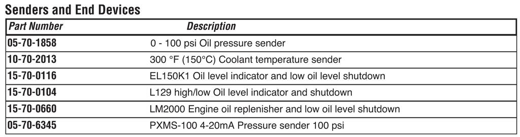
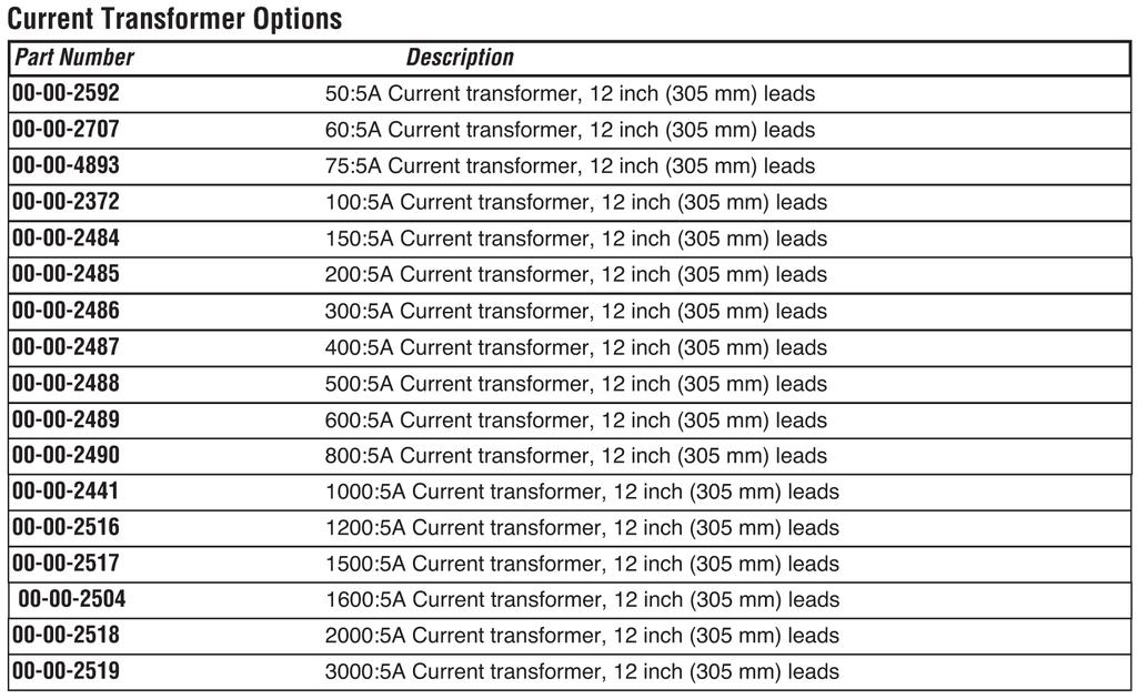
64 iguard Options and Accessories
 2011 Murphy Industries, Inc.")
65 MURPHY and the Murphy logo are registered and/or common law trademarks of Murphy Industries, Inc. This document, including textual matter and illustrations, is copyright protected by Murphy Industries, Inc., with all rights reserved. (c) 2011 Murphy Industries, Inc. Other third party product or trade names referenced herein are the property of their respective owners and are used for identification purposes only.
WARNING. Installation and Operations Manual for iguard TM Digital Generator Set Controller. Version 1.40+
 Installation and Operations Manual for iguard TM Digital Generator Set Controller Version 1.40+ IG-02117N Revised 02-09-05 Section 75 00-02-0522 Please read the following information before installing.
PowerView PV380-R2 Mechanical Configuration
 PowerView PV380-R2 Mechanical Configuration Operations Manual *Products covered in this document comply with European Council electromagnetic compatibility directive 2004/108/EC and electrical safety directive
Cascade CD101 Auto-Start Controller. Installation and Operations Manual Sections 40 & 75
 Cascade CD101 Auto-Start Controller Installation and Operations Manual 00-02-0594 2018-02-15 Sections 40 & 75 In order to consistently bring you the highest quality, full featured products, we reserve
Deep Sea Electronics Plc
 Deep Sea Electronics Plc 5120 AUTOMATIC MAINS FAILURE MODULE OPERATING MANUAL Author: Anthony Manton Deep Sea Electronics Plc Highfield House Hunmanby North Yorkshire YO14 0PH England Tel: +44 (0) 1723
TG350 User Manual. Manual Revision: Min. FW Revision: Date Released: 09/01/ DYNAGEN Technologies Inc
 TG350 User Manual Manual Revision: 1.4.0 Min. FW Revision: 1.42.01 Date Released: 09/01/2014 Table of Contents 1 Introduction 1.1 Specifications... 3 2 Installation 2.1 Terminal s... 6 2.2 Typical Wiring...
HGM6410/6420 AUTOMATIC GENERATOR MODULE WITH J1939 INTERFACE SOFTWARE MANUAL
 HGM6410/6420 AUTOMATIC GENERATOR MODULE WITH J1939 INTERFACE SOFTWARE MANUAL SMARTGEN ELECTRONICS Smartgen Electronic Equipment Co., Ltd No.12 Dongqing Street Zhengzhou Henan Province P.R.China Tel : (0086)-371-67992951
HGM6410/6420. Automatic Generator Module. With J1939 Interface OPERATING MANUAL. Smartgen Electronics
 HGM6410/6420 Automatic Generator Module With J1939 Interface OPERATING MANUAL Smartgen Electronics Smartgen Electronic Equipment Co,.Ltd No.12 Dongqing Street Zhengzhou Henan Province P.R.China Tel : (0086)-371-67992951
HGM1780 AUTOMATIC GENERATOR MODULE CONTENT 1. SUMMARY PERFORMANCE AND CHARACTERISTICS SPECIFICATION OPERATION...
 CONTENT 1. SUMMARY...4 2. PERFORMANCE AND CHARACTERISTICS...4 3. SPECIFICATION...5 4. OPERATION...6 4.1. DISPLAY PANEL...6 4.2. LCD ICON INSTRUCTION...7 4.3. DISPLAY INSTRUCTIONS...7 4.4. DISPLAY DESCRIPTION...8
HGM1780. Automatic Genset Controller USER MANUAL. Smartgen Technology
 HGM1780 Automatic Genset Controller USER MANUAL Smartgen Technology Smartgen Technology Co., Ltd No. 28 Jinsuo Road Zhengzhou Henan Province P. R. China Tel: 0086-371-67988888/67981888 0086-371-67991553/67992951
MPC-20 Engine Controller Operations Manual
 Software Release 2.8.10043 MPC-20 Engine Controller Operations Manual *Approved by CSA for non-hazardous locations (Group Safety Publication EIC 61010-1) Products covered in this document comply with European
HGM1770 Automatic Generator Control Module OPERATING MANUAL Smartgen Electronic
 HGM1770 Automatic Generator Control Module OPERATING MANUAL Smartgen Electronic CONTENT 1. SUMMARY... 4 2. PERFORMANCE AND CHARACTERISTICS... 4 3. SPECIFICATIONS... 5 4. OPERATION... 6 5. PROTECTION...
USER MANUAL ZHENGZHOU SMARTGEN TECHNOLOGY CO.,LTD
 HGM400 Series Genset Controller (HGM410/HGM420) USER MANUAL ZHENGZHOU SMARTGEN TECHNOLOGY CO.,LTD CONTENTS 1 OVERVIEW... 5 2 PERFORMANCE AND CHARACTERISTICS... 6 3 SPECIFICATION... 8 4 OPERATION... 9 4.1
Be2K-Plus AMF panel control wiring --
 Be2K-Plus OEM's Manual V200 - August - 014 page 1 Be2K-Plus AMF panel control wiring -- Consult Section 17.0 for software upgrades & revisions The information in this document may be subject to change
5220 AUTOMATIC MAINS FAILURE MODULE OPERATING MANUAL
 5220 AUTOMATIC MAINS FAILURE MODULE OPERATING MANUAL > Section DSE Model 5220 Automatic Mains Failure & Instrumentation System Operators Manual TABLE OF CONTENTS
HGM7100N SERIES (HGM7110N/7120N) GENSET CONTROLLER USER MANUAL
 GENSET CONTROLLER USER MANUAL") HGM7100N SERIES (HGM7110N/7120N) GENSET CONTROLLER USER MANUAL SMARTGEN (ZHENGZHOU) TECHNOLOGY CO., LTD. Chinese trademark English trademark SmartGen make your generator smart SmartGen Technology Co.,
HGM7100N SERIES (HGM7110N/7120N) GENSET CONTROLLER USER MANUAL SMARTGEN (ZHENGZHOU) TECHNOLOGY CO., LTD. Chinese trademark English trademark SmartGen make your generator smart SmartGen Technology Co.,
Generator Sets Controller 210. Operation Manual. Ver1.0
 Generator Sets Controller 210 Operation Manual Ver1.0 Note This information could include technical inaccuracies or typographical error. Manufacturer may make improvements and/or changes in the product(s)
MODEL 520 REMOTE START ENGINE MANAGEMENT SYSTEM
 MODEL 520 REMOTE START ENGINE MANAGEMENT SYSTEM DSE 520 ISSUE 4 4/4/02 MR 1 TABLE OF CONTENTS Section Page INTRODUCTION... 4 CLARIFICATION OF NOTATION USED WITHIN THIS PUBLICATION.... 4 1. OPERATION...
MPC-10 Engine Controller Operations Manual
 MPC-10 Engine Controller Operations Manual To see this manual in Spanish, German, French or Italian, please go to www.fwmurphy.com/mpc10 Software Release 2.08.10073.00 *Approved by CSA for non-hazardous
HGM6310D/6320D AUTOMATIC GENERATOR MODULE USER MANUAL
 HGM6310D/6320D AUTOMATIC GENERATOR MODULE USER MANUAL SMARTGEN ELECTRONIC CONTENT 1 SUMMARY... 4 2 PERFORMANCE AND CHARACTERISTICS... 4 3 SPECIFICATION... 6 4 OPERATION... 7 4.1 KEY FUNCTION... 7 4.2 AUTOMATIC
HGM6320T AUTOMATIC GENERATOR CONTROLLER USER MANUAL
 HGM6320T AUTOMATIC GENERATOR CONTROLLER USER MANUAL Smartgen Technology CONTENT 1 SUMMARY... 4 2 PERFORMANCE AND CHARACTERISTICS... 4 3 SPECIFICATION... 5 4 OPERATION... 6 4.1 LCD DISPLAY... 6 4.2 KEY
PowerCore MPC-10 Engine Controller & TEC-10 Panel Operations Manual
 PowerCore MPC-10 Engine Controller & TEC-10 Panel Operations Manual To see this manual in Spanish, German, French or Italian, please go to www.fwmurphy.com/mpc-10 www.fwmurphy.com/tec-10 In order to consistently
Operations Manual *Products covered in this document comply with European Council electromagnetic compatibility directive 2004/108/EC and electrical
 PowerView PV380-R2 Murphy Standard Configuration Operations Manual *Products covered in this document comply with European Council electromagnetic compatibility directive 2004/108/EC and electrical safety
AUTOSTART 705S V1.00 AUTOSTART 710S / 720S / 730S V1.04 Programming Reference and Check Sheets
 The Generator Controls Division of Frank W. Murphy AUTOSTART 705S V1.00 AUTOSTART 710S / 720S / 730S V1.04 Programming Reference and Check Sheets MODEX AUTOMATION FRANK W. MURPHY LTD. Church Road Laverstock
Model H30 Operation Manual
 Model H30 Operation Manual Model H30 Version 1.0 August 1, 2007 2 135 West Davenport Street Rhinelander WI 54501 Phone: 866.441.7997 Fax: 866.278.0036 info@houstonst.com www.houstonst.com 3 Table of Contents
OPERATING INSTRUCTIONS ECON-M
 OPERATING INSTRUCTIONS ECON-M INDEX 1.0 Introduction 2.0 Salient features, Protection & Supervision 3.0 Display/ Front Panel 4.0 Switches Description 5.0 LED Annunciations Description 6.0 Lamp Test 7.0
HGM6400 Automatic Genset Controller (With J1939 Interface) USER MANUAL Smartgen Technology
 USER MANUAL Smartgen Technology") HGM6400 Automatic Genset Controller (With J1939 Interface) USER MANUAL Smartgen Technology Chinese trademark English trademark Smartgen make your generator smart Smartgen Technology Co., Ltd No. 28 Jinsuo
HGM6400 Automatic Genset Controller (With J1939 Interface) USER MANUAL Smartgen Technology Chinese trademark English trademark Smartgen make your generator smart Smartgen Technology Co., Ltd No. 28 Jinsuo
Operations Manual *Products covered in this document comply with European Council electromagnetic compatibility directive 2004/108/EC and electrical
 PowerView PV350-R2 Murphy Standard Configuration Operations Manual *Products covered in this document comply with European Council electromagnetic compatibility directive 2004/108/EC and electrical safety
DEEP SEA ELECTRONICS PLC
 COMPLEX SOLUTIONS MADE SIMPLE. DEEP SEA ELECTRONICS PLC DSE5110 AUTOSTART CONTROL MODULE OPERATING MANUAL Deep Sea Electronics Plc Highfield House Hunmanby North Yorkshire YO14 0PH ENGLAND Sales Tel: +44
TG350 User Manual. Manual Revision: Min. FW Revision: Date Released: 18/12/ DynaGen Technologies Inc
 TG350 User Manual Manual Revision: 6.0.0 Min. FW Revision: 1.82.09 Date Released: 18/12/2017 TG350 User Manual Table of Contents User Guide 1 Introduction 4... 4 1.1 Specifications 2 Installation 6...
PowerCommand 1.1 control system
 Specification sheet PowerCommand 1.1 control system Description The PowerCommand control system is a microprocessor-based generator set monitoring, metering and control system designed to meet the demands
TG410 User Manual. Manual Revision: Min. FW Revision: Date Released: 18/12/ DynaGen Technologies Inc
 TG410 User Manual Manual Revision: 6.0.0 Min. FW Revision: 1.82.09 Date Released: 18/12/2017 TG410 User Manual Table of Contents User Guide 1 Introduction 4... 5 1.1 Specifications 2 Installation 6...
Rev 29. Caution
 9469200995 Rev 29 communication ports include a mini-b USB port, CAN terminals, and provisions for an optional Remote Display Panel. The following paragraphs describe the communication ports in detail.
GSC400 Series. Automatic Gen-Set Controller Manual. Revision 2.6
 GSC400 Series Automatic Gen-Set Controller Manual Revision 2.6 GSC400 Automatic Gen-Set Controller Installation and User Manual MAN-0076 Rev2.6, GSC400 User Manual.doc, May 2010 2 of 105 Thank You For
ICON 2 1. FEATURES AND CHARACTEIRICS
 ICON 2 1. FEATURES AND CHARACTEIRICS High end Micro-controller(DSP) technology Wide range of auxiliary supply: 7V to 45Vdc. Low power Consumption : 200 ma @ 12 V DC. Alphanumeric 16X4 or 16X2 LCD display
OPERATING MANUAL Digital Diesel Control Remote control panel for WhisperPower generator sets
 Art. nr. 40200261 OPERATING MANUAL Digital Diesel Control Remote control panel for WhisperPower generator sets WHISPERPOWER BV Kelvinlaan 82 9207 JB Drachten Netherlands Tel.: +31-512-571550 Fax.: +31-512-571599
DKG-109 AUTOMATIC MAINS FAILURE UNIT
 Tel: +90-216-466 84 60 Fax: +90-216 364 65 65 datakom@datakom.com.tr http://www.datakom.com.tr DKG-109 AUTOMATIC MAINS FAILURE UNIT FEATURES Automatic mains failure Engine control Generator protection
DEEP SEA ELECTRONICS PLC
 COMPLEX SOLUTIONS MADE SIMPLE. DEEP SEA ELECTRONICS PLC DSE710 AUTOSTART CONTROL MODULE OPERATING MANUAL Deep Sea Electronics Plc Highfield House Hunmanby North Yorkshire YO14 0PH ENGLAND Sales Tel: +44
Murphy PowerCore MPC-20-R2 Engine Controller Operations Manual
 Murphy PowerCore MPC-20-R2 Engine Controller Operations Manual *Approved by CSA for non-hazardous locations (Group Safety Publication EIC 61010-1, Third Edition) Products covered in this document comply
HGM6000K Series Automatic Generator Module OPERATING MANUAL Smartgen Electronic
 HGM6000K Series Automatic Generator Module OPERATING MANUAL Smartgen Electronic CONTENT 1 SUMMARY... 4 2 PERFORMANCE AND CHARACTERISTICS... 4 3 SPECIFICATION... 6 4 OPERATION... 6 4.1 KEY FUNCTION... 6
DKG-705 AUTOMATIC MAINS FAILURE AND REMOTE START UNIT WITH PARALLEL TO MAINS AND DUAL GENSET PARALLEL FEATURES
 Genset Automation Control Pte Ltd DKG-705 AUTOMATIC MAINS FAILURE AND REMOTE START UNIT WITH PARALLEL TO MAINS AND DUAL GENSET PARALLEL FEATURES FEATURES Automatic mains failure, Remote start operation,
HGM6320T AUTOMATIC GENERATOR CONTROLLER USER MANUAL
 HGM6320T AUTOMATIC GENERATOR CONTROLLER USER MANUAL Smartgen Technology Smartgen Technology Co., Ltd No. 28 Jinsuo Road Zhengzhou Henan Province P. R. China Tel: 0086-371-67988888/67981888 0086-371-67991553/67992951/67992952
DIGITAL GENSET CONTROLLER
 INSTRUCTION MANUAL for DGC-2000 DIGITAL GENSET CONTROLLER Digital Genset Controller Basler DGC-2000 Generator Voltage Generator Amps Generator Phase Generator Frequency Not In Auto Alarm Supplying Load
DKG-707 MULTI GENSET PARALLELLING UNIT WITH J1939 INTERFACE
 DKG-707 MULTI GENSET PARALLELLING UNIT WITH J1939 INTERFACE STANDARD FEATURES Automatic and manual start Multi genset synchronization (up to 8 gensets) Multi genset load sharing (up to 8 gensets) Both
GSC300 Auto Start Engine Controller
 GSC300 Auto Start Engine Controller Revision 2.9 Installation and User Manual for the GSC300 Auto Start Engine Controller File: MAN-0039 R2.9, GSC300 User Manual.doc May 2011 2 of 29 Thank You For Purchasing
Deep Sea Electronics Plc
 Deep Sea Electronics Plc 5520 Operators Manual Author Tony Manton Deep Sea Electronics Plc Highfield House Hunmanby Industrial Estate North Yorkshire YO14 0PH ENGLAND Tel +44 (0) 1723 890099 Fax +44 (0)
DKG-109J AUTOMATIC MAINS FAILURE UNIT
 DKG-109J AUTOMATIC MAINS FAILURE UNIT CANBUS VERSION FEATURES True RMS measurements Automatic mains failure ECU control and monitoring through J1939 CAN J1939 ECU warnings displayed as text Various engine
DKG-509 AUTOMATIC MAINS FAILURE UNIT
 DKG-509 AUTOMATIC MAINS FAILURE UNIT CANBUS AND MPU VERSIONS DESCRIPTION The controller is a comprehensive AMF unit for single genset standby or dual genset mutual standby operations. The unit is available
GENSET CONTROL MODULE A121A / A241A
 Technical Data Sheet GENSET CONTROL MODULE A121A / A241A Features: Models for both 12V and 24V systems. One model for both spark ignition and diesel engines. 4-alarm light outputs with lamp-test provisions.
Flight Systems. Replacement for KASSEC DESCRIPTION
 DESCRIPTION The is a universal generator controller that will start, stop, and provide engine protection for most generators. Universal replacement for both the 90353 and 90354 KASSEC Compatible with most
Be-K3 OEM s Manual --
 Be-K3 OEM's Manual V200 - July - 010 page 1 Be-K3 OEM s Manual -- Consult Section 17.0 for software upgrades & revisions The information in this document may be subject to change without notice. No part
HGM6100K Series Automatic Generator Module OPERATING MANUAL Smartgen Electronics
 HGM6100K Series Automatic Generator Module OPERATING MANUAL Smartgen Electronics All rights reserved. No part of this publication may be reproduced in any material form (including photocopying or storing
GSC400 Series. Automatic Gen-Set Controller Manual. Revision 2.5
 GSC400 Series Automatic Gen-Set Controller Manual Revision 2.5 GSC400 Automatic Gen-Set Controller Installation and User Manual Full Version File: GSC400 User Manual Rev2.5.doc, December 2009 2 of 98 Thank
DEEP SEA ELECTRONICS PLC
 COMPLEX SOLUTIONS MADE SIMPLE DEEP SEA ELECTRONICS PLC DSE720 AUTOSTART CONTROL MODULE OPERATING MANUAL http://bestgenerator.spb.ru/?page_id=6765 Deep Sea Electronics Plc Highfield House Hunmanby North
DKG-215 MANUAL AND REMOTE START UNIT
 DKG-215 MANUAL AND REMOTE START UNIT FEATURES Manual and remote starting and stopping Zero power consumption at rest Engine control mode available Generator protection Built in alarms and warnings 1 phase
GSC300 Auto Start Engine Controller
 GSC300 Auto Start Engine Controller Revision 2.12 Installation and User Manual for the GSC300 Auto Start Engine Controller File: MAN-0039 R2.12, GSC300 User Manual.doc June 2014 2 of 28 Thank You For Purchasing
PowerView PV380 R1 Murphy Standard Configuration
 2016-06-23 00-02-0943 Section 78 PowerView PV380 R1 Murphy Standard Configuration Operations Manual Products covered in this document comply with European Council electromagnetic compatibility directive
Te 803 Electronic Controller. Service, Operation & Technical Information Manual
 Te 803 Electronic Controller Service, Operation & Technical Information Manual WARNING! Technical descriptions and data given in this document are accurate, to the best of our knowledge, but can be subject
Deep Sea Electronics Plc
 Deep Sea Electronics Plc 550 Operators Manual Author Miles Revell Deep Sea Electronics Plc Highfield House Hunmanby Industrial Estate North Yorkshire YO14 0PH ENGLAND Tel +44 (0) 1723 890099 Fax +44 (0)
ECU-02 Ver2.1 Automatic Engine Control Unit Operators Manual
 ECU-02 Ver2.1 Automatic Engine Control Unit Operators Manual Headquarters : No.3, Lane 201, Chien Fu St., Chyan Jenn Dist., Kaohsiung, TAIWAN Tel : + 886-7-8121771 Fax : + 886-7-8121775 URL : http://www.kutai.com.tw
GSC300. Auto Start Engine Controller. Installation and User Manual for the GSC300 Auto Start Engine Controller. Full Version
 GSC300 Auto Start Engine Controller Installation and User Manual for the GSC300 Auto Start Engine Controller Full Version File: GSC300rev2.4.doc Dec. 08, 2005 2 Thank You For Purchasing This DynaGen Product
Murphy-Link Series Panels Models ML25, ML50, ML100 ML150, and ML300. Installation and Operations Manual Section 30
 Murphy-Link Series Panels Models ML25, ML50, ML100 ML150, and ML300 Installation and Operations Manual 00-02-0842 2012-07-06 Section 30 In order to consistently bring you the highest quality, full featured
DEEP SEA ELECTRONICS
 DEEP SEA ELECTRONICS DSE6010 MKII / DSE6020 MKII Configuration Suite PC Software Manual Document Number: 057-223 Author: Fady Atallah DSE6010 MKII / DSE6020 MKII Configuration Suite PC Software Manual
DEEP SEA ELECTRONICS DSE7110 MKII / DSE7120 MKII Configuration Suite PC Software Manual
 DEEP SEA ELECTRONICS DSE7110 MKII / DSE7120 MKII Configuration Suite PC Software Manual Document Number 057-185 Author: Fady Atallah DSE7110 MKII / DSE7120 MKII Configuration Suite PC Software Manual DSE7110
HAT700 Series HAT700/HAT700I/HAT700B/HAT700BI/HAT700S ATS CONTROLLER USER MANUAL
 HAT700 Series HAT700/HAT700I/HAT700B/HAT700BI/HAT700S ATS CONTROLLER USER MANUAL ZHENGZHOU SMARTGEN TECHNOLOGY CO.,LTD Software Version Version Date Note 1.0 2014-09-09 Original release. 1.1 2015-03-04
DGC-2020 DIGITAL GENSET CONTROLLER
 DIGITAL GENSET CONTROLLER Basler Electric s Digital Genset Controller (DGC-2020) is a highly advanced integrated genset control system. The DGC-2020 is perfectly focused, combining rugged construction
Automatic Genset Controller, AGC-4 Display readings Push-button functions Alarm handling Log list
 OPERATOR'S MANUAL Automatic Genset Controller, AGC-4 Display readings Push-button functions handling Log list DEIF A/S Frisenborgvej 33 DK-7800 Skive Tel.: +45 9614 9614 Fax: +45 9614 9615 info@deif.com
PowerCommand 2100 digital generator set control
 Specification sheet PowerCommand 2100 digital generator set control Description The PowerCommand 2100 control is a microprocessor-based generator set monitoring, metering and control system. The control
GENSET CONTROL MODULE A121H / A241H. User selectable time delays for engine start and engine stop (cool down).
.") Technical Data Sheet GENSET CONTROL MODULE A121H / A241H Features: Models for both 12V and 24V systems. One model for both spark ignition and diesel engines. 4-alarm light outputs with lamp-test provisions.
Technical Data Sheet GENSET CONTROL MODULE A121H / A241H Features: Models for both 12V and 24V systems. One model for both spark ignition and diesel engines. 4-alarm light outputs with lamp-test provisions.
HSC940 Genset Controller CONTENTS 1 OVERVIEW PERFORMANCE AND CHARACTERISTICS SPECIFICATION OPERATION KEY FUNCTIONS...
 CONTENTS 1 OVERVIEW... 4 2 PERFORMANCE AND CHARACTERISTICS... 5 3 SPECIFICATION... 7 4 OPERATION... 8 4.1 KEY FUNCTIONS... 8 4.2 INDICATOR LIGHT... 9 4.3 AUTO START/STOP OPERATION... 10 4.4 MANUAL START/STOP
Idle Timer Controller - ITC Freightliner MT45 Contact InterMotive for additional vehicle applications
 An ISO 9001:2008 Registered Company System Operation Idle Timer Controller - ITC805 2013-2018 Freightliner MT45 Contact InterMotive for additional vehicle applications The ITC805 system shuts down idling
Product Manual. Part Number: MVP-193 Mefi-6 ECU Revision: 1.0
 Product Manual Part Number: MVP-193 Mefi-6 ECU Revision: 1.0 Copyright Controls, Inc. P.O. Box 368 Sharon Center, OH 44274 Phone 330.239.4345 Fax 330.239.2845 www.controlsinc.com TABLE OF CONTENTS PRIOR
HGM6000K Series Automatic Generator Module USER MANUAL Smartgen Technology
 HGM6000K Series Automatic Generator Module USER MANUAL Smartgen Technology Chinese trademark English trademark Smartgen make your generator smart Smartgen Technology Co., Ltd. No. 28 Jinsuo Road Zhengzhou
GENSET CONTROL MODULE LEVEL 1 A121CM / A241CM. Special logic to re-establish cranking following a false start.
 Technical Data Sheet GENSET CONTROL MODULE LEVEL 1 A121CM / A241CM Features: Models for both 12V and 24V systems. One model for both spark ignition and diesel engines. 5-alarm light outputs with lamp-test
HGM1750 Genset Security Module USER MANUAL Smartgen Technology
 HGM1750 Genset Security Module USER MANUAL Smartgen Technology CONTENT 1. SUMMARY... 4 2. PERFORMANCE AND CHARACTERISTICS... 5 3. SPECIFICATION... 7 4. OPERATION... 8 5. PROTECTION... 9 6. PARAMETER RANGE
DIESEL Engine Fire Pump Controllers Features
 1-1 Printer / Recorder The industrial grade thermal printer is housed in a rugged steel enclosure within the controller. The on/off switch, feed and reset buttons are front accessible. A bi-color status
PowerCommand Digital generator set control
 Specification sheet PowerCommand Digital generator set control Description The PowerCommand TM control (3100) is a microprocessor-based generator set monitoring, metering, and control system. The control
PRESSURE GOVERNOR, ENGINE MONITORING, AND MASTER PRESSURE DISPLAY MODEL: TCA100
 Document Number: XE-TCA1PM-R0A TCA100 Rev0511 PRESSURE GOVERNOR, ENGINE MONITORING, AND MASTER PRESSURE DISPLAY MODEL: TCA100 FIRE RESEARCH CORPORATION www.fireresearch.com 26 Southern Blvd., Nesconset,
Energy Division
 Energy Division http://energy.tycoelectronics.com Installation and Operating Manual GEN-TRANS Automatic Generator Transfer Switch Controller with Metering Tyco Electronics UK Limited Crompton Instruments
DEEP SEA ELECTRONICS PLC
 COMPLEX SOLUTIONS MADE SIMPLE. DEEP SEA ELECTRONICS PLC DSE5220 AUTO MAINS FAILURE MODULE OPERATING MANUAL Deep Sea Electronics Plc Highfield House Hunmanby North Yorkshire YO14 0PH ENGLAND Sales Tel:
4.2 Component Identification
 Digital Control Panels Deep Sea Electronics 5220 4.1 General 4.2 Component Identification 4.3 The YML5220 Controller 4.4 Description of Controls 4.5 Navigation 4.5.1 General Navigation 4.5.2 The Event
PowerCommand. Digital Generator Set Control
 PowerCommand Digital Generator Set Control Description The PowerCommand Control (3100) is a microprocessor-based generator set monitoring, metering, and control system. The control provides an operator
Installation and Maintenance Instructions. World Leader in Modular Torque Limiters. PTM-4 Load Monitor
 World Leader in Modular Torque Limiters Installation and Maintenance Instructions PTM-4 Load Monitor 1304 Twin Oaks Street Wichita Falls, Texas 76302 (940) 723-7800 Fax: (940) 723-7888 E-mail: sales@brunelcorp.com
Water Specialist CK and EQ Control Valve Programming and Cover Drawing Manual
 Water Specialist CK and EQ Control Valve Programming and Cover Drawing Manual Page 2 CK and EQ Manual CK and EQ Manual Page 3 Table of Contents CK Front Cover and Drive Assembly...4 OEM General Programming
Application Engineering
 Application Engineering February, 2009 Copeland Digital Compressor Controller Introduction The Digital Compressor Controller is the electronics interface between the Copeland Scroll Digital Compressor
GENSET CONTROL MODULE
 HGM7200/HGM7100 Series AUTOMATIC GENSET CONTROL MODULE User Manual SMARTGEN TECHNOLOGY Smartgen Technology Co., Ltd No.28 Jinsuo Road Zhengzhou Henan Province P. R. China Tel: 0086-371-67988888/67981888
HGM9510 GENSET PARALLEL (WITH GENSET) UNIT USER MANUAL
 UNIT USER MANUAL") HGM9510 GENSET PARALLEL (WITH GENSET) UNIT USER MANUAL SMARTGEN (ZHENGZHOU) TECHNOLOGY CO.,LTD. Chinese trademark English trademark SmartGen make your generator smart SmartGen Technology Co., Ltd. No.
HGM9510 GENSET PARALLEL (WITH GENSET) UNIT USER MANUAL SMARTGEN (ZHENGZHOU) TECHNOLOGY CO.,LTD. Chinese trademark English trademark SmartGen make your generator smart SmartGen Technology Co., Ltd. No.
Spartan Controls Millennium Compressor Control Panel Operating Philosophy
 Project: Stock Revision 1 Page 1 Spartan Controls Millennium Compressor Control Panel Operating Philosophy Location: Stock Customer references: Vendor: Vendor document: Spartan Controls Ltd. Operating
Digital generator set control PowerCommand 3100
 Digital generator set control PowerCommand 3100 Description The PowerCommand 3100 Control is a microprocessor-based generator set monitoring, metering and control system. The control provides an operator
MPC-20 Software Configuration Tool Guide
 MPC-20 Software Configuration Tool Guide 00-02-0929 2014-03-28 Section 78 In order to consistently bring you the highest quality, full-featured products, we reserve the right to change our specifications
The measurements module provides the following engine features information:
 1. INTRODUCTION The CEM6 control board is a monitoring network signal and monitoring and control generator feeding device. The device consists of 2 different modules: - Visualization module. The visualization
ITCEMS950 Idle Timer Controller - Engine Monitor Shutdown Isuzu NPR 6.0L Gasoline Engine
 Introduction An ISO 9001:2008 Registered Company ITCEMS950 Idle Timer Controller - Engine Monitor Shutdown 2014-2016 Isuzu NPR 6.0L Gasoline Engine Contact InterMotive for additional vehicle applications
Auto Mains Failure AMF Controller AE10113
 Auto Mains Failure AMF Controller AE03 Auto Mains Failure DESCRIPTION AMF Controller AE03 is an Automatic Mains Failure controller, which activates the generator during power failure & vice versa. The
ANALOG CONTROL PANEL
 ANALOG CONTROL PANEL 1. AC VOLTS: Displays generator output in voltage. 2. AC FREQUENCY: Displays the speed of the generator set in Hertz. 3. Percent of Load: Displays percentage of load on the generator.
GENSET CONTROL MODULE LEVEL 0 A120A. User selectable time delays for engine start and engine stop (cool down).
.") Technical Data Sheet GENSET CONTROL MODULE LEVEL 0 A120A Features: One model for both spark ignition and diesel engines. 4-alarm light outputs with automatic lamp-test provision. Overspeed adjustment not
Technical Data Sheet GENSET CONTROL MODULE LEVEL 0 A120A Features: One model for both spark ignition and diesel engines. 4-alarm light outputs with automatic lamp-test provision. Overspeed adjustment not
GSC300. Auto Start Engine Controller. Installation and User Manual for the GSC300 Auto Start Engine Controller. Full Version
 GSC300 Auto Start Engine Controller Installation and User Manual for the GSC300 Auto Start Engine Controller Full Version File: GSC300_R2_6doc September 2009 LIMITED WARRANTY POLICY: The Northern Lights
! WARNING To avoid risk of electrical shock, personal injury or death; disconnect power to oven before servicing, unless testing requires power.
 Technical Information Electric Slide-In Range JES9750AAB/S/W JES9800AAB/Q/S/W JES9860AAB/S/W Due to possibility of personal injury or property damage, always contact an authorized technician for servicing
Axpert-CSS AMTECH DRIVES Axpert-CSS Amtech
 The Axpert-CSS is a range of Combination Soft Starter panels offered by AMTECH DRIVES. We also offer the module unit as an individual product, named as Axpert-Opti torque Soft Starter. This is only the
PowerCommand 2.2 control system
 PowerCommand 2.2 control system Control system description The PowerCommand control system is a microprocessor-based generator set monitoring, metering and control system designed to meet the demands of
Owner s Manual. MG2000 Speedometer IS0211. for use with SmartCraft Tachometer
 Owner s Manual MG2000 Speedometer for use with SmartCraft Tachometer IS0211 rev. E ecr#6395 08/2006 4/5/05 Changes 12/21 Index Description Available Functions for display page 1 Default Screens page 1
DEEP SEA ELECTRONICS PLC DSE3210 Configuration Suite Software Manual
 DEEP SEA ELECTRONICS PLC DSE3210 Configuration Suite Software Manual Document Number 057-152 Author : Paul Gibbons DSE3210 Configuration Suite Software Manual Issue 1 DSE3210 Configuration Suite Software