Asahi/America Actuation Basics
|
|
|
- Angela Day
- 6 years ago
- Views:
Transcription

1 Asahi/America Actuation Basics
2 Table of Contents: Electric Actuators... 3 Principal of Operation... 3 Electric Actuator Motors... 3 Switches... 3 Principal of Operation... 3 Types of Switches... 4 Typical Series 92 Electric Actuator... 5 Typical Series 94 Electric Actuator... 6 Specifications... 7 Enclosure Types According to NEMA Actuator sizing Electric Actuator Options Feedback Potentiometer Positioner Transmitter Cycle Length Controller (CLC) Mechanical Brake Center-Off Wire Control Failsafe Battery Back-up Voltages Local Remote Station Why Specify Electric Actuators? Pneumatic Actuators Principal of Operation Typical Series 79P PAG Pneumatic Actuator Specifications Actuator sizing Pneumatic Actuator Options Solenoid Valves Limit Switches Pneumatic Positioners Electro-Pneumatic Positioners Transmitter AS-I Bus Networks Declutching Manual Override Asahi America, Inc. Page 2 of 21
3 Electric Actuators Principal of Operation An electric actuator is basically a geared motor. The motor can be of various voltages and is the primary torque-generating component. To prevent heat damage from overwork or excessive current draw, electric actuator motors are usually equipped with a thermal overload sensor embedded in the motor windings. This sensor is wired in series with the power source; and opens the circuit should the motor be overheated, then closes the circuit when the motor reaches a safe operating temperature. An electric motor consists of an armature, electrical windings, and a gear train. When power is supplied to the windings, a magnetic field is generated causing the armature to rotate. The armature will rotate as long as there is power to the windings; when the power is cut, the motor stops. Standard end of travel limit switches, which are a necessity for an electric actuator, handle this task. Electric actuators rely on a gear train, which is coupled directly from the motor to enhance the motor torque and dictate the output speed of the actuator. The only way to change the output speed is to install a cycle length control module. This module allows an increase in cycle time only. If a decrease in cycle time is required, an alternate actuator with the desired cycle time must be used. Electric Actuator Motors There are two (2) types of motors used for electric actuators; uni-directional and bidirectional (commonly known as reversing motors). Uni-directional motors are motors in which the armature rotates in one (1) direction, causing the valve to rotate in one direction. These actuators are typically used with a ball valve and rotate in 90 or 180-degree increments strictly for an on/off type of service. Bi-directional motors or, reversing motors, are motors in which there are two (2) sets of windings allowing the armature to rotate in either direction depending on which set of windings is powered. One (1) set of windings controls the clockwise direction for closing a valve, while the other set of winding controls the counter-clockwise direction for opening the valve. A major benefit of a bi-directional actuator is precise flow control, as the actuator is not required to travel the full stroke to begin the reverse stroke. Switches Principal of Operation Electric current can flow only if the circuit is complete. An open circuit one that has a gap within it prevents an electrical device from operating. by creating a gap intentionally, we can turn the device on and off. That is what a switch does. Page 3 of 21
4 Inside of a switch are two or more terminals. When the switch is turned off, nothing connects the two terminals, and the circuit is interrupted just as if a wire were removed from the device. When the switch is turned on, the two terminals are connected, the circuit is closed, and the current can flow again. This opening and closing action occurs very quickly to prevent electrical sparking between the contacts. The current tries to bridge the gap between the contacts as the gap narrows; the heavier the current flowing in the circuit, the more electrical sparking can occur. Some switches operate with a tube of mercury, which conducts electricity. When the switch is on, the tube tilts, and mercury flows down between the two contacts. When the switch is off, the mercury flows away from the contacts, and the circuit is open. This design reduces the possibility of sparking and also makes operation quiet. Types of Switches Electrical switches are usually expressed in terms of the number of poles and throws that they contain. A pole is a component of the switch that is moved by the switch action to make or break electrical contact. The possible electrical connections that can be made by a given pole are called throws. Single Pole Single Throw (SPST) This switch has one moveable component, or a single pole. It also has only one possible connection, or a single throw, for that pole. The configuration of a single pole single throw is often abbreviated SPST. It is usually used as an on/off switch. Single Pole Double Throw (SPDT) This switch still has only one moveable component, but two possible connections, or throws. It is often found in a switchbox where the user may select between normally open or normally closed contacts. Normally open contacts provide an open circuit when the switch is in a free position, while normally closed contacts provide a closed circuit when the switch is in a free position. Double Pole Single Throw (DPST) This switch has two moveable components, so it has a double pole. There is only one connection for each pole, and therefore is a single throw. Double Pole Double Throw (DPDT) This switch has two moveable components, and therefore is a double pole. It also has two connections for each pole, so it s a double throw. This type of switch is often used in a switchbox to give the user an extra set of contacts to wire indicator lights or relays. Almost any switch configuration can be identified by applying these outlined principles. Page 4 of 21
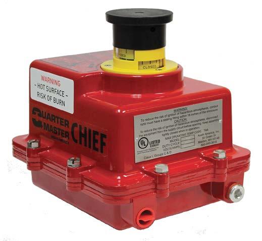
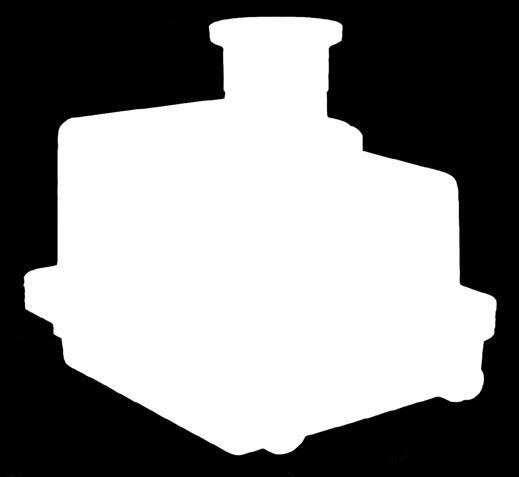
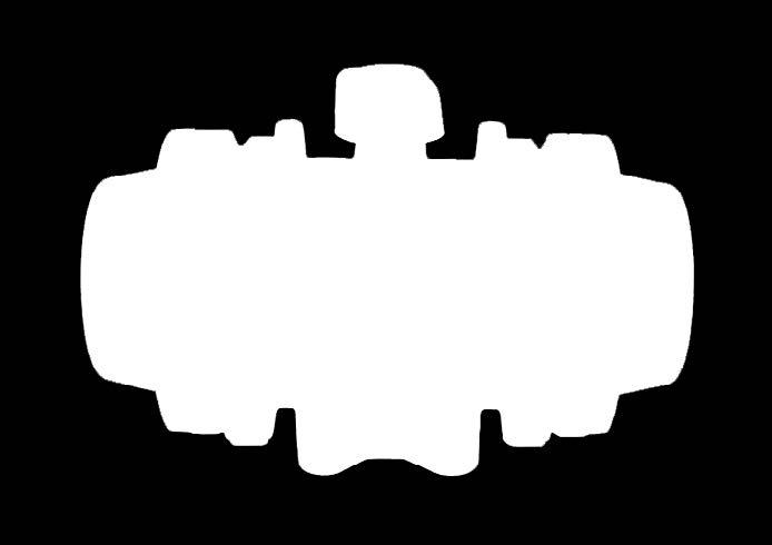
5 Typical Series 92 Electric Actuator Page 5 of 21
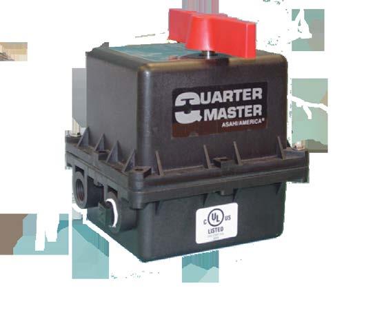
6 Typical Series 94 Electric Actuator Page 6 of 21
7 Specifications Electric actuators will usually have the following specifications: 1. HOUSING MATERIAL (such as Aluminum Alloy) This the material of the actuator housing. Asahi America utilizes a specially treated aluminum alloy for the Series 92 and Series 10, and Zytel FR50 for the Series HOUSING COATING MATERIAL (such as powder coat) This is the protective coating of the actuator housing (if any). Asahi America Series 92 and Series 10 have a thermally bonded powder coat finish. 3. ELECTRICAL PROTECTION: (such as NEMA 4X) A general guideline for enclosures is located on page 10. a. NEMA 4x - This is the rating for the enclosure as defined by the National Electrical Manufacturers Association (NEMA). The 4 designation that follows NEMA is a specific code that states that the enclosure is rated for indoor or outdoor use, and the X designates that the enclosure is non corrosive. Asahi America s Series 92, Series 10 and Series 94 have been designed with a NEMA 4x rated enclosure. b. NEMA 6 - This is the rating for the enclosure as defined by the National Electrical Manufacturers Association (NEMA). The 6 designation that follows NEMA is a specific code that states that the enclosure is rated for temporary submersion at a limited depth. Asahi America s Series 10 has been designed with a combination enclosure rating of NEMA 4x & NEMA 6. c. NEMA 7 - This is the rating for the enclosure as defined by the National Electrical Manufacturers Association (NEMA). The 7 designation that follows NEMA is a specific code that states that the enclosure is rated for use in Hazardous Locations. Asahi America s Series 92 has been designed with a NEMA 7 rated enclosure. d. ATEX Exd IIB T4 - This is the rating for the enclosure as defined by the National Electrical Manufacturers Association (NEMA). This designation is representative of an exclosure that is rated for use in Hazardous Locations. Asahi America s Series 92 and Series 10 have been designed with an ATEX rated enclosure. PLEASE NOTE THAT THE ABOVE SECTION DOES NOT IMPLY CERTIFICATION BY A THIRD PARTY, IT ONLY SUGGESTS THE PROTECTION LEVEL OF THE DESIGN REQUIREMENTS Page 7 of 21
8 4. OUTPUT TORQUE (such as 400 in/lbs) This the amount of torque (typically in in/lbs) that the actuator produces at the rated voltage and phase. Asahi America provides actuators that produce from 150 in/lbs to 48,000 in/lbs. 5. MOTOR TYPE (such as capacitor run) This details the motor type such as brushless, permanent capacitor (or capacitor run), etc. Asahi/America, Inc. provides brushless permanent capacitor motors in the Series 92, Series 10 and Series 94 electric actuator. 6. SWITCHES (such as SPDT) This details the type and rating for switches used in electric actuators (reference page 4). Asahi America s Series 92 and 94 use 2- SPDT 15Amp switches for end of travel, and 2-SPDT 8Amp switches for dry auxiliary contacts. These four switches are standard in the Series 92 & 94. The Series 10 uses 4-SPDT 10 Amp switches; two are end of travel, and two are dry auxiliary contacts. 7. MOTOR VOLTAGE AND PHASE (such as 120/1/60) This is the rated voltage, phase, and cycles (also known as hertz, Hz) for proper and safe operation of the motor. Optional voltages are also available. 8. GEAR TRAIN (such as heat treated) This is the detail of the gearing. Some manufacturers use a powdered/sintered metal or plastic gear train, which will often wear out or break prematurely. Asahi America provides electric actuators with solid alloy steel, Rockwell Hardened gears. 9. MANUAL OVERRIDE (such as declutching) This is a means of cycling the actuator without power. Some manufacturer s offer this and some do not. Also, for those who do offer, there is declutching and non-declutching. The difference is that a declutching manual override disengages the motor from the output gearing and output shaft, whereas non-declutching does not. So when the non-declutching manual override is used, the motor is winding backwards; often times damaging the windings and armature. Asahi America s electric actuators are of the declutching manual override design. 10. CONDUIT ENTRY (such as ½ FNPT) This is the pipe size and thread for electrical conduit connections. Asahi America Series 92 and Series 94 actuators are provided with two (2) ½ FNPT conduit entries. Series 10 actuators are provided with two (2) ¾ FNPT conduit entries. 11. DUTY CYCLE (such as 75%) This is a ratio of on time vs off time shown as a percentage. A higher percentage equals a higher on time rating. This rating is important in selecting an actuator. If you have a high cycle application and a low duty cycle, the motor is going to be overworked and burn out. Let s assume that an electric actuator will run for 10 seconds ( on time ) and then rest for 5 seconds ( off time ). We can compute the duty cycle as follows: Page 8 of 21
9 Duty cycle = Maximum on time Minimum off time Duty cycle = 10 seconds or, 10 5 seconds 5 Duty cycle = 50% For this application example, an electric actuator with a minimum duty cycle of 50% is required. An actuator with a higher duty cycle would be a better choice, such as a more common 75% duty cycle. 12. AMP DRAW (such as 1.0A) This is the amount of current required to cycle the actuator. Some manufacturers show this figure as a running current, while others show it as a locked rotor current, or stall current. Running current is just that, the current required to run or cycle the unit. Locked rotor current, or stall current, is the maximum current that the actuator will draw, even if something were to become lodged in the valve limiting its travel, thus locking the rotor, or stalling the motor. Asahi America publishes ALL amp draws as locked rotor, and believes that this aids electrical designers to properly design their system. 13. MAXIMUM AMBIENT TEMPERATURE (such as 150 F) This is the maximum ambient temperature for safe and proper operation. Asahi America electric actuators have a maximum temperature of 150 F. 14. MOUNTING CONFIGURATION (such as ISO 5211) This is a standard for the bolt circle and output shaft for the mounting of valves. Asahi America electric actuators meet ISO 5211 standards. 15. CERTIFICATION: a. UL APPROVAL/CERTIFICATION (SUCH AS UL508) This is a third party approval that certifies that the actuator has undergone and passed third party testing to a specific standard. Asahi America actuators have been certified to UL508, which is the standard for Industrial Control Equipment. (AKA: NEMA 4) b. UL APPROVAL/CERTIFICATION (SUCH AS UL1203) This is a third party approval that certifies that the actuator has undergone and passed third party testing to a specific standard. Asahi America Series 92 actuators can be certified to UL1203 (Class 1, DIV 1 & 2), which is the standard for Process Control Equipment for use in Hazardous Locations (AKA: NEMA 7, or Explosion Proof). Page 9 of 21
10 c. ATEX CERTIFICATION (SUCH AS Exd IIB T4) This is a third party approval that certifies that the actuator has undergone and passed third party testing to a specific standard. Asahi America Series 92 and Series 10 actuators can be certified to ATEX Exd IIB T4 (Equal to Class 1, DIV 1 & 2), which is the standard for Equipment use in Hazardous Locations (AKA: NEMA 7, or Explosion Proof). Page 10 of 21
11 Enclosure Types According to NEMA The following is from NEMA Standard #250 An enclosure is a surrounding case constructed to provide a degree of protection to personnel against incidental contact with the enclosed equipment and to provide a degree of protection to the enclosed equipment against specified environmental conditions Type 1 Enclosures are intended for indoor use primarily to provide a degree of protection against contact with the enclosed equipment. Type 2 Enclosures are intended for indoor use primarily to provide a degree of protection against limited amounts of falling water and dirt. Type 3 Enclosures are intended for indoor or outdoor use primarily to provide a degree of protection against windblown dust, rain, sleet, and external ice formation. Type 3S Enclosures are intended for indoor or outdoor use primarily to provide a degree of protection against windblown dust, rain, sleet, and to provide for operation of external mechanisms when ice laden. Type 4 Enclosures are intended for indoor or outdoor use primarily to provide a degree of protection against windblown dust and rain, splashing water and hose directed water. Type 4X Enclosures are intended for indoor or outdoor use primarily to provide a degree of protection against corrosion, windblown dust and rain, splashing water and hose directed water. Type 5 Enclosures are intended for indoor use primarily to provide a degree of protection against settling airborne dust, falling dirt, and dripping non-corrosive liquids. Type 6 Enclosures are intended for indoor use primarily to provide a degree of protection against the entry of water during occasional temporary submersion at a limited depth. Type 6P Enclosures are intended for indoor use primarily to provide a degree of protection against the entry of water during prolonged submersion at a limited depth. Type 7 Enclosures are for use in indoor locations classified as Class I, Groups A, B, C, or D, as defined in the National Electric Code. Type 8 Enclosures are for indoor or outdoor locations classified as Class I, Groups A, B, C, or D, as defined in the National Electric Code. Type 9 Enclosures are for use in indoor locations classified as Class II, Groups E, F, and G, as defined in the National Electric Code. Page 11 of 21
12 Type 10 Enclosures are constructed to meet the applicable requirements of the Mine Safety and Health Administration. Type 11 Enclosures are intended for indoor use primarily to provide, by oil immersion, a degree of protection to enclosed equipment against the corrosive effects of liquids and gasses. Type 12 Enclosures are intended for indoor use primarily to provide a degree of protection against dust, falling dirt, and dripping noncorrosive liquids. Type 13 Enclosures are intended for indoor use primarily to provide a degree of protection against dust, spraying water, oil, and noncorrosive coolant. Actuator sizing Actuator sizing is an important step to ensure the actuator can overcome the required valve torque. If the actuator does not produce enough output torque, it can not successfully cycle the valve to which it is coupled to. Most manufacturers use a safety factor when sizing an electric actuator. Asahi America s safety factor is 25%. Minimum actuator output torque is the product of the maximum valve torque and the safety factor, and can be computed using the following formula: Minimum actuator output torque = maximum valve torque (in/lbs) X 1.25 So: Maximum valve torque = (450 in/lbs)(1.25) Minimum actuator output torque = 562 in/lbs For a valve that requires 450 in/lbs of torque to operate, the actuator must produce a minimum of 562 in/lbs to properly cycle the valve. An A92XWJ produces 700 in/lbs and would be the actuator of choice for this application. Electric Actuator Options Feedback Potentiometer A 1000-ohm, 1 watt feedback potentiometer with 5% linearity can be installed for position feedback. The feedback potentiometer provides a varying degree opening percentage from ohms. This option is not used very often. Positioner A solid state PCB is installed inside of the actuator for precise modulating control. The standard positioner accepts 120vac supply voltage and a user selectable control signal of current or voltage. This positioner has 450 points of resolution in a 90 degree quadrant, is Page 12 of 21
13 pushbutton calibrated without the use of tools, and accept a transmitter via plug and socket. Transmitter A solid state PCB installed in the positioner via plug and socket will provide precise valve position to a PLC, DCS, etc. via a current or voltage signal. This is an output signal from the actuator NOT a control signal to the actuator. This is for reporting the precise valve position to the appropriate piece of equipment. Transmitter is also provided with 3 SPST relays; one for open position, one for closed position, and one for a fault condition. Cycle Length Controller (CLC) The CLC allows the field adjustment of the actuator cycle time up. This adjustment is for lengthening the cycle time, is accomplished by pulsing power to the motor. The CLC is configured at the factory for the combination of open and close cycles, and mounted inside of the actuator housing. Mechanical Brake This prevents oscillation typically found with rubber seated Butterfly Valves. The brake is installed on top of the motor armature and is electro-mechanical. When power is applied to the actuator, it is also applied to the brake, which releases the armature and allows the unit to cycle. When the power is lost the springs within the brake lock the armature so that it can no longer rotate, thus eliminating oscillation. Center-Off This option is used when a 90-degree off position is required while using a three-way ball valve. Two additional limit switches and two additional cams are installed in the unit (not to be confused with auxiliary limit switches) and allow three positions for a three way valve; 0 degrees or left port open, 180 degrees or right port open, and 90 degrees or off position. 2-Wire Control The two-wire control option is a relay installed inside of the actuator for direct wiring to timers, level switches, etc. A constant power supply and a SPST switch of some sort are required for cycling of the actuator. When the SPDT switch is closed, the valve opens, and vice versa. Failsafe Battery Back-up A solid state PCB along with a rechargeable battery pack is installed inside of the actuator. When power is lost, the unit will then travel to a pre-determined fail position. It is imperative that there be constant power to the unit to ensure that the battery pack maintain a full charge. Voltages Asahi/America, Inc. offers five voltage options to meet a variety of customer needs: 220vac, 12vdc, 24vdc, 12vac, 24vac Page 13 of 21
14 Local Remote Station The Local Remote Station is also known as a Control Station, and is used to electrically cycle the actuator independent of the control system. These stations typically have pushbutton and/or selector switches, and two position indication lights. Asahi/America, Inc. provides a 3-position selector switch, and a 2-position selector switch. The 3-position selector switch is for Hand-Off Auto selection. The hand mode is for controlling the actuator independent of the control system, the auto mode is for controlling the actuator via the control system, and the off mode disconnects power to the actuator. The 2- position selector switch is for Open or Close. By selecting the open or close switch, in hand mode, you can drive the actuator to either the open or close position. Asahi/America, Inc. supplies these stations with Green/Open and Red Close position indication lights as a standard. Why Specify Electric Actuators? Lack of an air supply, cold climate, PLC controlled process, etc. are all reasons to specify an electric actuator over a pneumatic actuator. In many remote locations, such as the Oil & Gas Industry, it may not be possible to provide an air compressor. In the Oil & Gas Industry, automated valves are located in an oilfield, literally in the middle of nowhere. That means no power supply for the air compressors, which typically run on 120vac or 240vac. This is overcome by using a low voltage electric actuator (12vdc) which is powered by a PLC, which is powered by a 12 volt battery, which is kept at full charge by a solar battery charger. So the required wattage would be 24 watts. On the other hand, if you were to try and use a similar solar system for a pneumatic system, the wattage required would be approximately 2400 watts. A cold climate is not a good choice for a pneumatic system. Water is found in all air systems, which is a component of the atmosphere. When lower temperatures are considered with pneumatics, there is always the possibility of freezing air lines. This could be potentially dangerous depending on the process and the process media. There could also be partial freezing within the actuator. If this happens, the cylinder walls become scored, providing an air leak by the pistons, which dramatically reduces output torque from the actuator. One might consider heat tracing the air lines and actuator. If there is low voltage available for heat tracing, that same power source could be used to power an electric actuator without the concerns of a freezing air system. Computer control systems (PLC, DCS, PID, PAC, etc.) are controlling more and more automated processes. These controllers can be wired directly to the electric actuators, streamlining the system. A pneumatic actuator would require a solenoid valve or a current to pneumatic, or I/P, converter that would wire to the controller, thus complicating the system. Along with the controller and components, an air compressor system would also be required. When all of the required components are factored in, the electric actuator is the best monetary choice. Page 14 of 21
15 Pneumatic Actuators Pneumatic actuators are available in many different styles such as rack and pinion, scotch yoke, vane, etc. These actuators are available as single acting (spring return) or double acting (air open/air close). ALL pneumatic actuators have the same principle of operation. Principal of Operation Pressurized air enters the actuator and pushes against the inside of the housing and a piston or a vane. This pressure forces the piston(s) or vane to move, thus rotating the output shaft in one direction and typically opening the actuator (CCW rotation). If the actuator is double acting, then the air is removed from the open port and introduced through the close port. This channels the air to the opposite side of the piston(s) to rotate the output shaft in the opposite direction; thus closing the actuator (CW rotation). If the actuator is single acting, there are a set of springs that are on the opposite side of the piston(s) or vane that compress during the open stroke. When the air supply is removed, the stored energy in the compressed springs forces the piston(s) or vane back to its original position (typically closed CW rotation). Spring return actuators are also known as failsafe actuators. This is due to the spring action upon the loss of supply air. Most of the time spring return actuators a setup for a failsafe closed position; meaning that the actuator will close upon loss of air supply. These actuators can also be setup for a failsafe open position; meaning that the actuator will open upon loss of air supply. Since the actuator works backwards in a failsafe open application, the actuator will need to be reconfigured for this operation. Therefore, it is imperative that a failsafe open application be specified to the manufacturer prior to shipment, as many actuators can not be reconfigured in the field. Some pneumatic actuators can be powered by other means, such as nitrogen gas, water, oil, etc. One must make sure that the power source is compatible with the actuator materials, so that there are no potential corrosion issues to hamper the operation of the actuator. One should also work with the manufacturer for proper material selection of actuator and actuator components. Page 15 of 21
16 Typical Series 79P PAG Pneumatic Actuator Specifications Pneumatic actuators usually have the following specifications: 1. BODY MATERIAL (such as Aluminum Alloy) This the material of the actuator body. Asahi America has three body materials available: Rilsan coated aluminum alloy, Glass-filled Polyamide, and 316SS. 2. BODY COATING MATERIAL (such as being Anodized) This is the protective coating of the aluminum alloy actuator body. Asahi America utilizes a combination of cataphoresis and Rilsan coating inside and outside. 3. END CAP MATERIAL (such as Aluminum Alloy) This is the material of the actuator end caps. Asahi America uses the same material for the end caps as for the body. 4. END CAP COATING MATERIAL (such as being Anodized) This is the protective coating of the aluminum alloy actuator end caps. Asahi America utilizes a combination of cataphoresis and Rilsan coating inside and outside. Page 16 of 21
17 5. EXTERNAL HARDWARE MATERIAL (such as SS) These are the nuts and bolts used to assemble the actuator. Asahi America uses 303SS for actuators constructed of aluminum alloy and glass-filled Polyamide, and 316SS for the actuators constructed of 316 SS. 6. OUTPUT SHAFT MATERIAL (such as 304 SS) This is the material of the actuator s output shaft. Asahi America uses 304SS, 316SS or cataphoresis coated carbon steel; depending on actuator body materials and actuator size. 7. O-RING MATERIAL (such as Self-lubricating BUNA-N) This is the material of the O-Rings found within the pneumatic actuator. Asahi America uses a selflubrication Buna N material. 8. PISTON MATERIAL (such as Polyarilamide) This is the material that the pistons are constructed of. In some actuators, steel pistons are used. This can be a problem if powered with water, and also if powered from a moist air supply. Asahi America uses polyarilamide or aluminum alloy; depending on actuator size. 9. PISTON GUIDE MATERIAL (such as Polyacetal) This is the material of the piston guides. Piston guides prevent the pistons from side-loading which robs output torque. Asahi America uses polyacetal or PTFE/Bronze; depending on actuator size. 10. TEMPERATURE RANGE (such as -25 F to 195 F) This is the ambient temperature range for safe and proper operation. Asahi America s standard actuators have a temperature range of -25 F to 195 F. For temperatures higher than 195 F, Asahi America offers a HT actuator (which is 316SS with High temperature o-rings installed) that has an upper temperature limit of 450 F. 11. OUTPUT TORQUE (such as 576 in/lbs) This the amount of torque (typically in in/lbs) that the actuator produces at a specific air supply pressure. Asahi America provides actuators that produce from 60 in/lbs to 40,441 in/lbs based on an 80 psi air supply. 12. AIR CONNECTIONS (such as ¼ FNPT) This is the pipe size and thread for air inlet ports. Asahi America actuators are provided with ¼ FNPT air inlets. 13. AIR SUPPLY PRESSURE (such as 80 psi) This is a specified air inlet pressure to obtain a certain amount of output torque. As pressure increases, so does the output torque; and vice versa. 14. MOUNTING DIMENSIONS (such as ISO 5211, NAMUR) These are standards for the mounting of accessories such as solenoid valves or positioners. Asahi America actuators meet both of these standards. Page 17 of 21
18 Actuator sizing Actuator sizing is an important step to insure the actuator can overcome the required valve torque. If the actuator does not produce enough output torque, it can not successfully cycle the valve to which it is coupled to. Most manufacturers use a safety factor when sizing a pneumatic actuator. Asahi America s safety factor is 25%. Minimum actuator output torque is a product of the maximum valve torque and the safety factor, and can be computed using the following formula: Minimum actuator output torque = maximum valve torque (in/lbs) X 1.25 So: Maximum valve torque = (450 in/lbs)(1.25) Minimum actuator output torque = 562 in/lbs For a valve that requires 450 in/lbs of torque to operate, the actuator must produce a minimum of 562 in/lbs, based on the proper air supply, to properly cycle the valve. The CP79PN air to air actuator produces 575 in/lbs at 80 psi and would be the actuator of choice for this application. The DP79PSN air to spring actuator produces 582 in/lbs at 80 psi and would be the actuator of choice for this application. Pneumatic Actuator Options Solenoid Valves Solenoid valves are a necessity for cycling pneumatic actuators. These electric valves allow air to enter specific ports of the actuator based on their design type. Solenoid valves are available as 2-way, 3-way, 4-way, etc. So you must be cautious when selecting solenoid valves. Design Styles 2-way solenoid valves operate as open or closed. 3-way solenoid valves operate as a multi-port valve with one port being an inlet, one port being an outlet, and the third port being exhaust. 3-way solenoid valves are used with single acting actuators. 4-way solenoid valves also operate as a multi-port valve with one port being an inlet, two ports being outlets, and two ports being exhaust. 4-way solenoid valves are used with double acting actuators. Specifications Solenoid valves usually have the following specifications: Page 18 of 21
19 1. DIRECT OR REMOTE MOUNT This specifies the location of the solenoid. Direct mount is mounted directly to the actuator, while Remote Mount is mounted on a manifold and piped to the actuator ports. The standard solenoid for Asahi America, Inc. is Direct Mount. 2. PIPE SIZE (such as ¼ FNPT) This is the pipe size and thread for the inlet and outlet ports for a remote mount solenoid, or the pipe size and thread for the inlet port of a direct mount solenoid. The standard inlet/outlet pipe size for Asahi America, Inc. is ¼ FNPT. 3. ELECTRICAL PROTECTION (such as NEMA 4X) This is the rating for the enclosure as defined by the National Electrical Manufacturers Association (NEMA). A general guideline for enclosures is available on page 7. The standard Electrical Protection level for Asahi America, Inc. is NEMA 4X. 4. COIL VOLTAGE (such as 120vac) This is the voltage that will energize the coil and have the solenoid change states and allow air to enter the actuator, thus cycling the unit. 120vac is the standard voltage for Asahi America, Inc. 5. MAXIMUM INLET PRESSURE (such as 125 psig) This is the maximum allowable inlet pressure allowed without causing damage and also to operate safely. It is very important that the maximum inlet pressure of the solenoid be equal or higher than the actuator. 6. TEMPERATURE RANGE (such as 32 F to 125 F) This is the recommended temperature range for safe and proper operation. Limit Switches Auxiliary limit switches, are used for interlocking with other equipment or valves. They are also widely used as valve position confirmation (end of travel) with a PLC, DCS, etc. 2-SPDT switches with a 15 amp rating are mounted inside of a NEMA 4X enclosure. This enclosure has SS trim, is mounted on top of the actuator, and direct coupled with the actuator output shaft. Pneumatic Positioners The pneumatic positioner accepts variable pneumatic instrumentation signals (typically between 3 and 15 psig) and regulates the 80-psi air supply to the actuator via a characterized cam, diaphragm, and spool. The diaphragm receives an input pressure signal from the controller, which applies force to the spool valve spring causing the spool valve to move. This movement modifies the air pressure to the actuator, permitting the actuator to respond accordingly. The characterized cam transmits the actuator movement to the spool valve. Electro-Pneumatic Positioners The electro-pneumatic positioner accepts variable electrical instrumentation signals (between 4 and 20 milliamps) from a PLC, DCS, set point controller, etc. and regulates Page 19 of 21
20 the 80-psi air supply to and from the actuator via an on-board I/P converter. This process regulates the actuator position within its quadrant for precise modulation. Transmitter A transmitter installed in the positioner will provide precise valve position to a PLC, DCS, etc. via a current signal (typically between 4 and 20 milliamps). This is an output signal from the actuator NOT a control signal to the actuator. This is for reporting the precise valve position to the appropriate piece of equipment. The transmitter is standard piece of equipment within an Asahi America, Inc. positioner. AS-I Bus Networks AS-I (Actuator-Sensor Interface) offers many of the benefits of more complex and costly bus systems, but does it at a substantially lower cost and with greater simplicity. The Actuator-Sensor Interface is ideally suited for controlling valves, actuators and many other field devices in a processing application. This interface can be used for stand-alone process control, or it can be used together with a higher-level bus control system. AS-Interface does not compete with higher-level bus systems; it should be seen as a complimentary system that offers low cost, reliable device control for binary and analog devices. Reliability, simplicity and interoperability make AS-Interface a cost effective connection/control solution, particularly where low installation costs is imperative. A single pair of wires, which handles power and communications, is used to control the network by means of chaining the actuators with the PLC. Each actuator (or device) will then have its own unique address within the system and only that device with the proper address will respond to system commands. ASI is best known for its yellow flat cable, which is pierced by insulation displacement connectors so that the expense of tees and complex connectors is avoided. Devices are simply clamped onto the cable. Digital signals are encoded on this cable in a sinusoidal signal, which has a very narrow frequency bandwidth. Filtering which is distributed through the network rejects all extraneous frequencies, and in this way ASI can be operated in electrically noisy environments without experiencing transmission errors. The yellow flat cable carries low current (30 VDC) for input devices as well as the AS-I signal. If power for outputs (such as energizing relays) is required, an additional BLACK flat cable is available. Standard networking is capable of 62 units with a distance up to 100 meters, and a cycle time of 5ms. A maximum of 300 meters is achieved by installing repeaters. This system also responds well with products from other manufacturers, by installing a gateway to translate the commands of higher-level networks. This allows an existing system to be expanded simply by using the AS-I networking system. Page 20 of 21


21 There are various wiring structures which can be used with this system such as the star, ring, branch, tree, etc. All are practiced and acceptable, but the loop has a distinguished property; if there were a break in the network cable the units would still cycle and the master would detect the loss of a node, and set off an alarm. This feature is unique to the ring structure. These wiring structures can be reviewed below. Declutching Manual Override A declutching manual override is a gear operator that has an offset input handwheel shaft assembly that either engages or disengages with the internal worm gear. When the shaft assembly is disengaged, the actuator cycles normal and the handwheel will rotate freely. When the shaft assembly is engaged, the handwheel must be rotated to manually open or close the actuator. This should only be done when there is no air pressure to the actuator. It is imperative that the valve torque and the actuator torque be used in the sizing equation for air to spring actuators, as the manual override gear box must overcome to valve torque as well as the spring torque. Page 21 of 21

 442-7244 West (800) 282-7244 Fax:")
22 655 Andover St., Lawrence, MA Tel: ; Direct Sales: East (800) Central (800) West (800) Fax:
Actuation & Controls. Pneumatic Actuators Electric Actuators PLC AS-i-Bus Systems Positioners. ASAHI/AMERICA Rev.
 Actuation & Controls Pneumatic Actuators Electric Actuators PLC AS-i-Bus Systems Positioners www.asahi-america.com www.asahi-america.com asahi@asahi-america.com Tel: 800-343-3618 781-321-5409 Fax: 800-426-7058
ASAHI/AMERICA. Series 79. Positioners
 ASAHI/AMERICA Actuation and Controls Series 79 Positioners s and 35 Green Street, P.O. Box 653, Malden, MA 0248 Tel: 800-343-368 78-32-5409 Fax: 800-426-7058 E-mail: asahi@asahi-america.com 23 Register
E Series Electric Actuators
 ENGINEERING MANUAL 13560 Larwin Circle, Santa Fe Springs, CA 90670 Phone: (562) 802-2255 (800) 783-7836 Fax: (562) 802-3114 Netsite: www.svf.net E-mail: Sales@SVF.net E Series Electric Actuators 1/4 3
Double Acting & Spring Return. SERIES 92/93 Rack & Pinion PNEUMATIC ACTUATOR. The High Performance Company
 PNEUMATIC ACTUATOR SERIES 92/93 Rack & Pinion Double Acting & Spring Return The High Performance Company SERIES 92/93 Styling, strength, compactness, and simplicity of design have been combined to produce
PP Series Pneumatic Actuators
 PDF Published February 4, 07 PP Series Pneumatic Actuators for Chemline ball valves up to 6 MATERIAL: Polyamide SERIES: PPS Spring Return PPD Double Acting CONTROL PRESSURE: 40 to 0 psi OUTPUT TORQUES:
PG Series 180º Rotation Pneumatic Actuators
 PDF Published April 18, 2016 PG Series 180º Rotation Pneumatic Actuators for Chemline 3-way ball valves up to 4 material: Epoxy and Rilsan coated aluminum SERIES: PGS Spring Return PGD Double Acting control
Technical Specification. RCS Electric Actuators with a ProfiBus Field Control and Communication Module
 The following specification defines the minimum requirements for the supply of motor operated valve actuators with a field communication bus system for remote control. The complete system shall consist
Electric Actuator Options & Accessories
 The basic options and accessories listed in this section represent many of the most commonly used for electric actuation, factory configured to order on the actuation package. Contact Spears for any desired
COMPLETE LISTING OF OPTIONS. Toggles, Lights
 COMPLETE LISTING OF Toggles, Lights A001 A002 Local Auto/Manual Toggle Switch - NEMA 4. Switch for Auto (i.e. 4-20 ma from control room), or Manual (local control at actuator). Switch is maintain type.
Quarter Master Chief Series 92 Actuator
 Quarter Master Chief Series 92 Actuator Installation, Operation and Maintenance Manual File: Series 92 O & M manual Rev. V 4/22/2013 Page 1 of 13 Table of Contents Series 92 Electric Actuator Introduction...
CONTROLS. Bray Pneumatic Actuators & Accessories. Technical Manual. A Division of BRAY INTERNATIONAL, Inc.
 CONTROLS A Division of BRAY INTERNATIONAL, Inc. Bray Pneumatic Actuators & Accessories Technical Manual TM-056 Pneumatic Actuator - 08//00 Bray Pneumatic Actuators & Accessories Technical Manual - Table
Electric Actuator Accessories. Timer Board 115 VAC Input Suffix A (For EVR, EVS & EVT actuators)
") Timer Board Suffix A Timer board installs within actuator enclosure. Board shown is for EVR, EVS, and EVT actuators. Cycle Time Rate Regulator Suffix B Cycle time rate regulator installs within actuator
Timer Board Suffix A Timer board installs within actuator enclosure. Board shown is for EVR, EVS, and EVT actuators. Cycle Time Rate Regulator Suffix B Cycle time rate regulator installs within actuator
Engineering Information. Solenoid Valves Principles of Operation. Solenoid Valves. Direct Acting Valves (Figures 1A, 1B)
") 4 Engineering Information Principles of Operation A solenoid valve is a combination of two basic functional units: A solenoid (electromagnet) with its core A valve body containing one or more orifices
4 Engineering Information Principles of Operation A solenoid valve is a combination of two basic functional units: A solenoid (electromagnet) with its core A valve body containing one or more orifices
PP Series Pneumatic Actuators
 PDF Published September 9, 0 PP Series Pneumatic Actuators for Chemline ball valves up to 6 for Chemline butterfly valves up to 6 MATERIAL: Polyamide SERIES: PPS Spring Return PPD Double Acting CONTROL
Quarter Master Series 94 Actuator
 Quarter Master Series 94 Actuator Installation, Operation and Maintenance Manual Assembly Series 94 Manual Rev V 9/5/13 Page 1 of 12 Table of Contents Series 94 Electric Actuator Introduction... 3 Description...
+GF+ PNEUMATIC ACTUATED BALL VALVE +GF+ PNEUMATIC ACTUATED BALL VALVE +GF+ PNEUMATIC ACTUATED BALL VALVE 3-16
 +GF+ PNEUMATIC ACTUATED BALL VALVE Type 21/2 2-way True Union Pneumatically actuated ball valve for aggressive fluids and industrial applications. Based on the new Type 546 ball valve, the Type 21-2 uses
SERIES 1000 ELECTRIC ACTUATORS
 DESIGN FEATURES Series 1000 On-Off Rotary Electric Actuator Basic Actuator: Torque Output Range: 347in-lb to 17,359in-lb Housing: NEMA 4X, watertight, corrosion-resistant, robust aluminum die cast Electric
A Compact and Reliable Quarter-Turn Electric Actuator
 A Compact and Reliable Quarter-Turn Electric Actuator Benefits The HQ Series Electric Quarter Turn Actuators are an extension of Emerson s world famous EIM Electric Actuators. The HQ offers a compact,
Pneumatic Actuators. Series 79P (Aluminum) Series 79P (Glass-filled Polyamide) Series 79P (316 Stainless Steel)
 Series 79P (Glass-filled Polyamide) Series 79P (316 Stainless Steel)") Series 79P (Aluminum) Pneumatic Actuators Specifications Series 79 P: Type: Double Piston, Double Rack and Pinion Bodies: Aluminum, Glass-filled Polyamide, and 316 ss Torque: 59 to 40,710 in-lbs. s Air-to-Air
Series 79P (Aluminum) Pneumatic Actuators Specifications Series 79 P: Type: Double Piston, Double Rack and Pinion Bodies: Aluminum, Glass-filled Polyamide, and 316 ss Torque: 59 to 40,710 in-lbs. s Air-to-Air
Z-Tech Severe Chemical Service Valves We Put Control Where You Need It.
 Z-Tech Severe Chemical Service Valves We Put Control Where You Need It. Z-Tech Series Valves TABLE OF CONTENTS Ball Valves ZT 4 Series: Three Piece Flanged Ball Valve... -3 Pneumatic Actuators and Accessories...
Series 10 Actuator. Installation, Operation and Maintenance Manual
 Series 10 Actuator Installation, Operation and Maintenance Manual File: series10.man Location: assembly/manual Rev.E 6/24/14 Page 1 of 8 Table of Contents Series 10 Electric Actuator Introduction... 3
Automation Selection Guide
 A Bray High Performance Company A Subsidiary of BRAY INTERNATIONAL, Inc. Automation Selection Guide Automator Products Pneumatic & Electric Actuators And Accessories PDF processed with CutePDF evaluation
Installation and Operating Manual
 . Installation and Operating Manual WE/XE-690, 1350, 1700, 2640, 4400, 5200, 6900, 10500 17500, 25690 1 (Rev. 020113) IOM8011.docx . Table of Contents Introduction Page Safety Instructions..... 3 Introduction
K10 Intrinsically Safe Electro-Pneumatic Positioner Operating Manual
 K0 Intrinsically Safe Electro-Pneumatic Positioner Operating Manual Pneumatic Connection Outlet Port Gauge Single Acting Actuator (Spring Return): For single acting actuators Outlet Port 2 is to be plugged.
brands you trust. CRANE - Automation Actuators and Instrumentation
 brands you trust. CRANE - Automation Actuators and Instrumentation Automation Capabilities Overview CRANE Energy Flow Solutions provides a variety of valve automation products, including pneumatic and
Automation is the techniques and equipment used to achieve automatic operation or control.
 VALVE AUTOMATION What is Automation? Automation is the techniques and equipment used to achieve automatic operation or control. Automation is an automatic operation and control of machinery or processes
Actuators & Positioners Pneumatic Actuators Series UP1/2/3/4/5/6
 Data Sheet Actuators & Positioners Pneumatic Actuators Series UP1/2/3/4/5/6 Wide Range of Torque Ratings - Six actuator sizes available in ratings from 122 to 6372 Newton meters (90 to 4700 foot-pounds)
Electric Actuators Maximum in-lbs
 Maximum 14040 in-lbs NEMA 4, 4X, 7 ER- Series Features ISO / DIN valve interface Mounting in any position Thermal overload protection (AC & DC except 12 VDC) Friction brake (standard for AC motors except
Electric Actuators Maximum in-lbs
 Maximum 14040 in-lbs NEMA 4, 4X, 7 ER- Series Features ISO / DIN valve interface Mounting in any position Thermal overload protection (AC & DC except 12 VDC) Friction brake (standard for AC motors except
Quarter turn actuators Index
 Index General information page Introduction 227 Product information Pneumatic actuators page Double acting and spring return 228 page Index 231 ECON Compact 232 EL-series 234 ELQ-series 236 Hydraulic actuators
How to Select Automation Accessories for Valves
 How to Select Automation Accessories for Valves Today's process controls range from complete computer systems to the staffmonitored electromechanical type (push buttons, heavy-duty relays, etc.). In the
VALVITALIA VALVE OPERATORS
 A Long Experience in Energy Equipment and one Goal: The Customer s satisfaction. VALVITALIA VALVE OPERATORS 1 VALVITALIA AUTOMATION DIVISION PROFILE Valvitalia Automation Division manufactures all type
Mid-West Instrument. Piston Type Model 220. Hazardous Locations. Indicating / Non-Indicating Differential Pressure Switch or Transmitter
 BULLETIN NO. 220/11 (SUPERSEDES BULLETIN NO. 220/06) Mid-West Instrument Piston Type Model 220 Hazardous Locations Indicating / Non-Indicating Differential Pressure Switch or Transmitter Low cost piston
Proximity Sensors. Reference Information. Principles of Operation. Proximity Sensors
 Reference Proximity Sensors Principles of Operation Inductive Proximity sensors are generally constructed with four main elements: (1) a coil and ferrite core assembly; (2) an oscillator; (3) a convertor/trigger
Q u a r t e r T u r n E l e c t r i c A c t u a t o r s
 Quarter Turn Electric Actuators A101/04 2 Q uarter-turn actuators are used to operate ball, plug or butterfly valves, dampers, vents and any equipment with quarter-turn or part turn travel. BERNARD has
TABLE OF CONTENTS MC SERIES RACK & PINION ACTUATOR PAGE 1 MC SERIES OPTIONS PAGE 2 LIMIT SWITCHES, POSITIONERS LB SERIES ACCESSORIES PAGE 8
 Supersedes ACT-1101 Dated NOVEMBER 5, 2001 TABLE OF CONTENTS MC SERIES RACK & PINION ACTUATOR PAGE 1 MC SERIES OPTIONS PAGE 2 CB & HD SERIES YOKE PNEUMATIC ACTUATORS PAGE 3 SOLENOID VALVES PAGE 4 LIMIT
SERIES 1000 ELECTRIC ACTUATORS
 SERIES 1000 ELECTRIC ACTUATORS DESIGN FEATURES Series 1000 On-Off Rotary Electric Actuator Standard Features SERIES 1000 ELECTRIC ACTUATORS Torque Output Range: 434in-lb to 17,700in-lb Housing: NEMA 4,
Installation, Operation and Maintenance Manual
 HQ 005. ELECTRIC ACTUATORS QUARTER-TURN ELECTRIC ACTUATORS Installation, Operation and Maintenance Manual s Version Ver. 1 Revision Rev. 1 Document No. HKQI-611 Small & Compact Design High corrosion resistance
Automation Capabilities
 Crane Valves North America Automation Capabilities Summary of Capabilities Automation Crane Valves North America provides a variety of valve automation products, including pneumatic and electric actuators,
Type 57 Butterfly Valve
 Standard Features (Sizes -/" ") Standard model (-/" ") has Body and Disc for superior chemical resistance and elevated temperature capabilities 6/ stainless steel shaft has full engagement over the entire
Series Electric Actuators
 Electric Actuators Electric Actuators Series 44000 Electric Actuators ELECTRIC ACTUATORS With maintenance-free operation, the Crane 44000 electric actuator is ideal for small to medium diameter valves
The JR Linear Drive System
 D A M P E R D R I V E S TM The JR Linear Drive System Technical Data Sheet TDS JR-1000 ROTARY + LINEAR DAMPER DRIVES TABLE OF CONTENTS SECTION PAGE NUMBER 1. Introduction 3 2. Applications 3 3. Features
Pneumatic Actuators. 1. DIE CAST ALUMINUM END CAPS: standard polyester powder coated
 4 5 Pneumatic s 1 2 6 NOMINAL VALUES: Pressure rating max 115 PSI Temperature range: standard (-4 F;+185 F), high (-4 F;+302 F), low (-40 F;+185 F) Pre lubricated for life of actuator at assembly 100%
Mid-West Instrument. Diaphragm Type Model 240. Hazardous Locations. Indicating / Non-Indicating Differential Pressure Switch or Transmitter
 BULLETIN NO. 240/11 (SUPERSEDES BULLETIN NO. 240/06) Mid-West Instrument Diaphragm Type Model 240 Hazardous Locations Indicating / Non-Indicating Differential Pressure Switch or Transmitter Field wireable
TABLE OF CONTENTS ACT1212 SUPERCEDES ACT0311 MC SERIES RACK & PINION ACTUATOR PAGE 1 MC SERIES OPTIONS PAGE 2
 TABLE OF CONTENTS ACT1212 SUPERCEDES ACT0311 MC SERIES RACK & PINION ACTUATOR PAGE 1 MC SERIES OPTIONS PAGE 2 CBA & HD SERIES YOKE PNEUMATIC ACTUATORS SOLENOID VALVES REMOTE MOUNT LIMIT SWITCHES, POSITIONERS
DA-053 Series. Overview. Applications. Features & Benefits. Datasheet. 53lb-in (6 Nm), Non-Spring Return Damper Actuators
, Non-Spring Return Damper Actuators") Datasheet 53lb-in (6 Nm), Non-Spring Return Damper Actuators Overview The direct-coupled fail-safe/failin-place electronic actuators are designed for modulating, two position, and floating control of laboratory
Datasheet 53lb-in (6 Nm), Non-Spring Return Damper Actuators Overview The direct-coupled fail-safe/failin-place electronic actuators are designed for modulating, two position, and floating control of laboratory
Type Installation, Operation and Maintenance Instructions. Ordering Information. Contents CA20 -
 Type 2000 Pneumatic and Electropneumatic Valve Positioner Installation, Operation and Maintenance Instructions Ordering Information Use this coding system to order Model CA20 - Type of Positioner 00 P/P
Cam-Lok Single Pole Connectivity. The industry standard for reliable service under the most severe operating conditions.
 Cam-Lok Single Pole Connectivity The industry standard for reliable service under the most severe operating conditions. Cam-Lok Single Pole Connectivity Cam-Lok connectors are the industry standard Cam-Lok
APS & APIS ATEX AIRPOWER SWITCH BOXES FEATURES DESCRIPTION
 page 1 DESCRIPTION The switch boxes are suitable for rotary actuators and are the industry leader in versatility, quality and approvals gained. Models include APS standard range with a variety of outputs
Electric Fast Packs. Pneumatic Fast Packs
 Nine different styles Ships within 24 hours from time of order! Electric or pneumatic actuators Ball or butterfly valve Electric Fast Packs Type-21 Ball Valves Type-57 Butterfly Valves Series 83 Series
Easytork Solenoid Valve IOM
 Easytork Solenoid Valve IOM General This installation document is to be read in conjunction with the Easytork Vane Actuator IOM. Description The Easytork Solenoid Valve ( ESV ) series is intended for the
Bray Series 70 Electric Actuator. Basic Product/Sales School
 Bray Series 70 Electric Actuator What is the Bray S70? Electric Quarter Turn Valve Actuator Physically fits small to midsize valves Three Housing Sizes Ten Torque Ratings S70 Electric Actuator Sizes Housing
Control Valves Positioner
 Control Valves Positioner HiFlo Valve Positioner Easy calibration Corrosion-resistant cover and base Withstands 150 psi at all parts Two -sided cam for easy field reversibility Optional / NPT for piped
Control Valves Positioner
 Control Valves Positioner HiFlo HiFlo Valve Positioner Corrosion-resistant cover and base Easy calibration Withstands 150 psi at all parts Two -sided cam for easy field reversibility Optional / NPT for
Model 5000 Level Controller
 Features Multiple Configurations The 5000 level controller is easily configured for either reverse or direct actions for both pneumatic and electric pilot options. The pneumatic pilot is available in snap
VALVCON ADC-SERIES ELECTRIC ACTUATOR WITH OPTIONAL BATTERY BACK-UP POWER
 VALVCON ADC-SERIES ELECTRIC ACTUATOR WITH OPTIONAL BATTERY BACK-UP POWER Metso is a leading designer and provider of Valvcon compact, reliable, electronically controlled electric actuators for valves and
Actuated Valves PRICING
 Electric & Pneumatic Actuated Valves Actuated Valves PRICING Page Suitable for Oil-Free air handling to 5 psi, not for distribution of compressed air or gas Spears Manufacturing Company Due to Material
Spring Cylinder Rotary Actuator
 Spring Cylinder Rotary Actuator Rotary Actuator Spring Cylinder Rotary Actuators High torque and pneumatic stiffness combine together in the Mascot "Spring cylinder rotary actuator" These characteristics
range to scotch-yoke pneumatic & hydraulic actuators, rack and pinion actuators and relevant control systems.
 Company Profile History Elfor Controls, established in the last 70 s, is an Italian company specialized in engineering and manufacturing a complete range of valves actuators and related accessories. The
Electric Actuator EQ Series
 Electric Actuator EQ Series Engineering Creative Solutions for Fluid Systems Since 1901 INTRODUCTION Pratt Industrial designs and provides high quality actuators and services related to valve automation.
VALVES / ACTUATORS COMPLETE PRODUCT LINE / BRAYLINE ACCESSORIES. The High Performance Company
 VALVES / ACTUATORS COMPLETE PRODUCT LINE / BRAYLINE ACCESSORIES The High Performance Company BRAY CONTROLS Bray Controls is proud to offer our high performance, highest quality product lines. Through years
Series 72 Electri-SAFE On/Off Operation Including CLC Option Installation, Operation and Maintenance Instructions
 WCAIM2049 (Part 18960) Series 72 Electri-SAFE On/Off Operation Including CLC Option Installation, Operation and Maintenance Instructions Series 72 actuators are electro-hydraulic quarterturn valve actuators.
SECTION CONTROL VALVE ACTUATORS
 SECTION 23 09 13.34 - CONTROL VALVE ACTUATORS PART I GENERAL 1.0 OVERVIEW [Background for PSC] A. Control Valve/Actuator Applications 1. See Exhibit 23 09 13.33-1, Control Valve/Actuator Worksheet for
TorqPlus TM Electric Valve Actuators and Controls
 TorqPlus TM Electric Valve Actuators and Controls Introduction For more than 40 years, Bettis Corporation has been recognized worldwide for providing industry with high performance pneumatic and hydraulic
System Electropneumatic Converters (Proportional Valves) Electronic Process Controllers Signal Converters
 Electronic Process Controllers Signal Converters") System 6000 Electropneumatic Converters (Proportional Valves) Electronic Process Controllers Signal Converters Edition April 2018 Information Sheet T 6000 EN Electropneumatic Converters i/p converters
System 6000 Electropneumatic Converters (Proportional Valves) Electronic Process Controllers Signal Converters Edition April 2018 Information Sheet T 6000 EN Electropneumatic Converters i/p converters
CML Electric Actuator for Baumann Series
 Electronic Actuators Product Bulletin CML Electric Actuator for Baumann 4000 Series CML-50 and CML-750 electronic modulating valve actuators feature state-of-the-art brushless DC motor technology to provide
MAQ Series Electric Actuator
 Series Electric Actuator Series INTRODUCTION KEYVALVE designs, produces and provides high quality actuators and services related to valve automation. - Our long years experience in automation field enables
Models UP1/2/3/4/5/6/7 Universal pneumatic rotary actuators. Measurement made easy. High performance actuators for precision damper control
 Data sheet DS/A/UP EN Rev K Models UP1/2/3/4/5/6/7 Measurement made easy High performance actuators for precision damper control Wide range of torque ratings Seven actuator sizes available in ratings from
Pneumatic/Electric Actuators. Catalog 4123 August 2004
 Pneumatic/Electric Actuators Catalog 4123 August 2004 Pneumatic Actuators Introduction Parker 60 Series spring return (AC/AO) or double acting (AD) rack and pinion actuators are compact, simply designed
ivp PROGRAM FNW Ball Valves
 ivp PROGRAM FNW Ball Valves PROGRAM OVERVIEW For actuation and accessories, FNW utilizes Wolseley Industrial Group Valve & Automation, or WIGVA. This facility located in Portland, Oregon is a premier valve
EIM CONTROLS HQ-SERIES QUARTER TURN ELECTRIC ACTUATORS
 EIM CONTROLS HQ-SERIES QUARTER TURN ELECTRIC ACTUATORS CONTENTS HQ Overview...3 Standard Configuration...4-5 Optional Features...6 Capacities & Ratings...7 Basic Outline Dimensions...8 Optional Control
ELECTRIC ACTUATORS. Series 70 Pgs 4-11 PRODUCT QUALITY & PRECISION INTRODUCTION
 R Electric Actuators & Accessories 1 ELECTRIC ACTUATORS Series 70 Pgs 4-11 Lb-Ins Torque Output N-m CONTROLS Series 70 Sizes 003-065 003 300 34 R 006 600 68 008 800 90 012 1200 136 020 2000 226 030 3000
Flowrite Globe. Pneumatic 4-inch Valve Actuator. Valves. Description. Applications. Features D-141.
 Flowrite Globe Pneumatic 4-inch Valve Actuator Flowrite 4-inch Pneumatic Valve Actuator. Designed for use with the Flowrite valves, the Flowrite 4-inch Pneumatic Valve Actuator has a 3/4-inch (20 mm) stroke
Proximity Sensors. Reference Information. Principles of Operation. Proximity Sensors
 Reference Proximity Sensors Principles of Operation Inductive Proximity sensors are generally constructed with four main elements: (1) a coil and ferrite core assembly; (2) an oscillator; (3) a convertor/trigger
Compact Electric Actuated Ball Valves PVC Body, Teflon/EPDM Seals 1/2 to 1 inch Pipe
 Compact Electric Actuated Ball Valves PVC Body, Teflon/EPDM Seals 1/2 to 1 inch Pipe SERIES Features Industrial quality miniature actuator Industrial grade True Union ball valve Visual valve position indicator
PISTON STYLE GAUGE. Mid-West Instrument
 PISTON STYLE GAUGE Mid-West Instrument 1 BULLETIN NO. 120/11 (SUPERSEDES BULLETIN NO. 120/02) Mid-West Instrument Piston Type Differential Pressure Gauges Switches & Transmitters Model 120 A low cost differential
AE Installation Operation & Maintenance Instructions
 AE-1400 Installation Operation & Maintenance Instructions IMPORTANT Please read the installation operation and maintenance instruction prior to using any Jomar Valve component. Failure to follow the instructions
OpenAir Electronic Damper Actuators GLB Series Enhanced Non-spring Return Rotary
 Document No. 155-785 OpenAir Electronic Damper Actuators GLB Series Enhanced Non-spring Return Rotary Description The OpenAir direct coupled enhanced non-spring return rotary electric actuators are designed
R-type, RY-type EPR-Series. Actuators for Quarter-Turn Valves
 R-type, RY-type EPR-Series Actuators for Quarter-Turn Valves >> Introduction The EPR-Series pneumatic actuator provides a rugged solution for quarter-turn actuation while reducing maintenance requirements.
Customized ELECTRO-HYDRAULIC CONTROL SYSTEM
 Customized ELECTRO-HYDRAULIC CONTROL SYSTEM ELECTRO-HYDRAULIC CONTROL SYSTEM 2 Since the founding of Automation Technology (ATI) more than 20 years ago, we have been recognized for innovation and dependability
QUARTER-TURN ELECTRIC ACTUATORS
 QUARTER-TURN ELECTRIC ACTUATORS PRODUCT FEATURES & BENEFITS Sizes: QTE-1.5 / QTE-3.0 / QTE-6.0 Motor split-phase, capacitor driven; 25% Duty cycle 24/115/230VAC, 80% Duty Cycle 12/24 VDC Gearing hardened
CONTROLS INC. Position Indicators. Valve Positioners
 Position Indicators Valve Positioners Apex 5000 The Apex 5000 Pneumatic Positioner provides accurate valve positioning with advanced features. It may be used with 3-15 psi pneumatic control signals, or
Moniteur INSTALLATION & OPERATING INSTRUCTIONS. SERIES 40 Positioners. Installation and Operating Instructions Series 40 Positioners.
 INSTALLATION & OPERATING INSTRUCTIONS SERIES 40 Positioners Form IO2-0406 Description of Device Moniteur's Series 40 pneumatic (3-15psi) and electropneumatic (4-20mA) positioners are advanced control devices
GE Energy. The Becker * DNGP: Fail-Safe Protection for Your Gas Pipeline
 GE Energy The Becker * DNGP: Fail-Safe Protection for Your Gas Pipeline DNGP with Modbus Communication protocol features ZERO Bleed * technology and control logic designed for natural gas control valves
Pneumatic Actuator Accessories. Discrete, NEMA 4, Four-Way Air/Air Suffix A2 (For PAD3 & PKD2 actuators)
") Air connections to actuator Discrete, NEMA 4, Four-Way Air/Air Suffix A2 (For PAD3 & PKD2 actuators) Integral, NEMA 4, Four-Way Air/Air Suffix A8 (For PKD3, PKD5, PKD7, & PKD9 actuators) Suffix A3 Air
Air connections to actuator Discrete, NEMA 4, Four-Way Air/Air Suffix A2 (For PAD3 & PKD2 actuators) Integral, NEMA 4, Four-Way Air/Air Suffix A8 (For PKD3, PKD5, PKD7, & PKD9 actuators) Suffix A3 Air
SECTION SECTION. EATON 2014 Arrow Hart Buyers Guide
 F SECTION SECTION 1 EATON 2014 Arrow Hart Buyers Guide FSECTION Cam-lok Single Pole Connectivity Table of contents Product selector guide F-3 NEMA rating system F-4 F-series F-5 E1010 F-6 E1012 F-7 F-series
VALVCON I-SERIES I6600 OPTION DN DEVICENET PROTOCOL
 VALVCON I-SERIES I6600 OPTION DN DEVICENET PROTOCOL Installation, Maintenance and Operating Instructions IMO-I6600 1/2014 2 IMO-I6600 Table of Contents 1 GENERAL.................................... 3 1.1
IMI vibration switch USER MANUAL INSTALLATION - OPERATION - MAINTENANCE
 USER MANUAL IMI vibration switch INSTALLATION - OPERATION - MAINTENANCE Z0929039_A ISSUED 03/2017 READ AND UNDERSTAND THIS MANUAL PRIOR TO OPERATING OR SERVICING THIS PRODUCT. contents Overview General
SM-1000 SERIES ROTARY ACTUATORS
 SM-1000 SERIES ROTARY ACTUATORS GENERAL DESCRIPTION The SM-1000 Series are multi-turn, rotary actuators, designed to meet the exacting requirements for closed-loop modulating positioning control. Designed
Safe & Secure Series Electric Actuator with Internal Battery Back-up Installation, Operation & Maintenance Manual
 Safe & Secure Series Electric Actuator with Internal Battery Back-up Installation, Operation & Maintenance Manual For Use with: SNS4, SNS6, SNS10 & SNS15 Models Additional supplements may be needed for
SECTION SECTION SECTION EATON 2016 Arrow Hart Buyers Guide
 F SECTION SECTION SECTION 1 EATON 2016 Arrow Hart Buyers Guide www.arrowhart.com /arrowhart FSECTION Cam-Lok Single Pole Connectivity Table of contents Product selector guide F-3 NEMA rating system F-4
Cam-Lok. Single pole connectivity. The industry standard for reliable service under the most severe operating conditions.
 Plugs & receptacles Cam-Lok single pole connectivity Cam-Lok Single pole connectivity The industry standard for reliable service under the most severe operating conditions. Cam-Lok single pole connectivity
J3C-L Nm Smart Electric Valve Actuator Failsafe Function Type: J3C Model: L140-BSR
 Failsafe Function Type: JC Model: L140-BSR Feature rich J+J multi-voltage smart electric actuator with LED status light and function conversion kits. Overview The JC-L140 low voltage electric valve actuator
Actuators & Positioners Models UP1/2/3/4/5/6/7. Universal Pneumatic Rotary Actuators
 Data Sheet D-A-UP_G Actuators & Positioners Models UP1/2/3/4/5/6/7 Universal Pneumatic Rotary Actuators Wide Range of Torque Ratings Six actuator sizes available in ratings from 122 to 7320 Newton meter
POSITION TRANSMITTERS
 POSITION TRANSMITTERS GENERAL DESCRIPTION Jordan Control s Series of position transmitters are rugged, compact industrial components that couple a precision feedback component and/or limit switches to
Actuation and Controls Price List Effective: 02/03/2014
 ACT-0214 Actuation and Controls Price List Effective: 02/03/2014 Revised 01/26/18 Suggested list prices are subject to change without notification. Visit our Website for the most up-to-date product information.
INSTRUCTION MANUAL ACTUATOR CLASSE I TYPE MA, MB
 ACTUATOR CLASSE I TYPE MA, MB CONTENTS Page : 2/13 PRODUCT DESCRIPTION General description 3 Product specification 5 INSTALLATION Storage 6 Unpacking 7 Handling 7 Installation : Mechanical 7 Installation
Electric Actuator Installation, Operation & Maintenance Manual
 ICI Indelac Controls, Inc. Electric Actuator Installation, Operation & Maintenance Manual 6810 Powerline dr.-florence, Ky. 41042 - Telephone 859-727-7890, Tool free 800-662-9424 Fax. 859-727-4070, e-mail:
Chapter 11: Valves and Actuators with the NAMUR-interface
 Right of authorship: the content of the training (wording, drawings, pictures) are owned by the author. Any utilization except for individual use is allowed only after permission of the author. Valves
MANTECH ELECTRONICS. Stepper Motors. Basics on Stepper Motors I. STEPPER MOTOR SYSTEMS OVERVIEW 2. STEPPING MOTORS
 MANTECH ELECTRONICS Stepper Motors Basics on Stepper Motors I. STEPPER MOTOR SYSTEMS OVERVIEW 2. STEPPING MOTORS TYPES OF STEPPING MOTORS 1. VARIABLE RELUCTANCE 2. PERMANENT MAGNET 3. HYBRID MOTOR WINDINGS