E24 SOLUTIONS Manual
|
|
|
- Audrey Short
- 6 years ago
- Views:
Transcription


1 E SOLUTIONS Manual COPYRIGHT 0 HYTROL CONVEYOR COMPANY, INC. BULLETIN NO. 0
2 Contents Motors PowerCubes Control Cards Ei Installation Guide Diagnostics and Troubleshooting Application Information E Standard Control Card Installation Guide Diagnostics and Troubleshooting Card Requirements Application Information 9 E Transfer Control Card 0 Installation Guide Diagnostics and Troubleshooting Card Requirements Trouble Shooting E A Card Installation Guide Diagnostics and Troubleshooting Card Requirements What is Standard? Advanced EZLogic Controls Global Speed Controller EEZ Transfer Merge EZLogic Control Function 9 This function controls the traffic in the area of a transfer merge in Hytrol model EEZ conveyors. The transfer merge function provides a traffic cop control for an incoming conveyor line merging onto a trunk conveyor line at 90 onto a pop-up transfer when both conveyors are zero-pressure conveyors equipped with EZLogic zone controllers. All of the control is provided by the EZLogic controllers, and minimal to no wiring is required at installation. Spur Merge EZLogic Control Function This function controls the traffic in the area of a spur merge. It requires a connection kit to connect the merge controller with the spur discharge zone. The spur-merge function provides a traffic cop control for a spur conveyor line merging onto a trunk conveyor line when both conveyors are zero-pressure conveyors equipped with EZLogic zone controllers. All of the control is provided by the EZLogic controllers, and no wiring of any kind is required at installation. Square Merge EZLogic Control Function This function controls the traffic in the area of a square merge. The square merge function provides a traffic cop control for an incoming conveyor line merging onto a trunk conveyor line at 90 when both conveyors are zero-pressure conveyors equipped with EZLogic zone controllers. All of the control is provided by the EZLogic controllers, and minimal wiring is required at installation. E Transfer Drawing and Parts List E Single Diverter E Double Diverter E Powered Transition Roller 9 E Gate 0 EEZ Gate Wiring Diagrams E Motor E Motors E Motors EZLogic Zones & E Motor per Zone EZLogic Zone & E Motor per Zone EZLogic Zone & E Motors per Zone EZLogic Zones & E Motors per Zone
 W 9W 0W W 9W Speed (Rated) 0 RPM 0 RPM 0 RPM 0 RPM 0 RPM Speed (Minimum) 0 RPM RPM 0 RPM 90 RPM RPM Torque (Continuous) in-lbf in-lbf in-lbf in-lbf in-lbf Torque")
3 ) Motors Below is a chart of the different standard V motors: Motor Size W (Ei ) 00W W 0W 00W Hytrol P/N Voltage VDC VDC VDC VDC VDC Amperage (Rated).A.0A.0A.A.0A Amperage (No Load) 0.A 0.A 0.A 0.A 0.A Watts (Rated) W 9W 0W W 9W Speed (Rated) 0 RPM 0 RPM 0 RPM 0 RPM 0 RPM Speed (Minimum) 0 RPM RPM 0 RPM 90 RPM RPM Torque (Continuous) in-lbf in-lbf in-lbf in-lbf in-lbf Torque (Starting) to in-lbf in-lbf in-lbf in-lbf in-lbf The Ei (W) motor has a built in motor control card mounted on it. The other motors all require a separate motor control card. See Section for motor control cards information. ) PowerCubes Below is a chart of the different standard V PowerCube motors: Motor Size W (Ei ) W 0W 0W 00W 00W Reducer Ratio :.: :.: :.: Hytrol P/N Voltage VDC VDC VDC VDC VDC VDC Amperage (Rated).0A.0A.A.A.0A.0A Speed (Maximum) 0 RPM. RPM 90 RPM 0 RPM RPM. RPM Speed (Minimum) RPM 9. RPM RPM RPM. RPM.9 RPM Torque (Min. Continuous) Torque (Max. Continuous) 0 in-lbf at 0 RPM 0 in-lbf at RPM or lower 0 in-lbf at. RPM 0 in-lbf at 9. RPM 0 in-lbf at 90 RPM 0 in-lbf at RPM 0 in-lbf at 0 RPM 0 in-lbf at RPM 0 in-lbf at RPM 0 in-lbf at. RPM 0 in-lbf at. RPM 0 in-lbf at.9 RPM Notes: ) There is not a 00W motor available for the PowerCube. ) Other ratios are available: :,.:, 0:, :, 0:, :, and 0:. ) The characteristics of the motor are such that torque increases as the speed decreases. ) The motors used on the Powercube are not the same as the motors used on the E conveyor. The motors used in PowerCubes have a shorter round shaft in lieu of the D shaft used on the E conveyor. Figure A Ø0. M 0. Deep, pl.. sq. key.0 long... Ø.9 Ø0.. dia All mounting holes sized for M fasteners.09 Lead Assembly =
 Standard control card that is used with the standard 00W motor. Hytrol Part Number 0.0900. ) Transfer control card that is used with the E Transfers. Hytrol Part Number 0.0900. ) A card that is selectable to power the 00W, W, 0W or 00W motors.")
4 ) Control Cards Hytrol has four different motor control cards. ) Ei control card that is integrated with the motor. Hytrol Part Number ) Standard control card that is used with the standard 00W motor. Hytrol Part Number ) Transfer control card that is used with the E Transfers. Hytrol Part Number ) A card that is selectable to power the 00W, W, 0W or 00W motors. This is standard when used with the PowerCube motors. Hytrol Part Number Figure A.) Ei (Hytrol Part Number 0.090) ) Cover - The cover can help reduce the severity of damage to the controller caused by foreign objects. Caution: The cover does not make the controller waterproof nor dust proof. Removal of the cover will void the warranty. ) LED Feedback Indicators - The control board contains four () LED feedback indicators: One () Amber Motor Current Limiting LED One () Red Fault LED One () Green Power LED One () Red Blown Fuse LED ) Configuration Switches - The control reads the configuration switches only when the unit is powering up. To change a setting, disconnect power, set the switch, and then reconnect the power. As shown in Figure A: Ei Control Components, the OFF position is to the Left and the ON position is to the Right. Configuration Switch Settings: Switch Description: OFF Setting: ON Setting: Rotation Direction Counter-Clockwise Clockwise Braking Action Zero-Motion Hold Coast Speed Selection See Table for Operating Speeds ) M Connector for EZLogic - The M connector is already configured for use with the Hytrol EZLogic control. ) Optional Input-Output (I/O) Connection Header - A -pin Phoenix PT./-PVH-. plug is supplied. If these I/O connections are not being used, leave the connector in place to avoid accidentally shorting the pins. Note: All inputs and outputs except analog are PNP only and are active at + VDC or higher. ) DC Power Input Header - The Ei operates off a + to + Volt DC power supply. The control reads the configuration switches only when the unit is powering up. Make the power connection only after all other connections have been made. Optional Inputs and Outputs Pinout: Caution: Power must be applied with the proper polarity to avoid potentially damaging the controller. Note: When adjacent zones are operating from separate power supplies, you should connect their DC grounds. However, do not connect the positive voltage wires from separate power supplies together. Pin Descrption Run (Input) Reverse (Input) Analog Input + Running (Output) DC Power Inputs Pinout: Pin Signal + to + Volts DC DC Ground L L L L ON Installation Guide Select a Speed - Four () switches determine the operating speed, making it simple to match speed in multiple zones. There is also an option to use a 0-0V DC input for dynamic remote speed adjustments while the system is running. Operating Speeds: SPEED, FPM RPM STD SPEED UP Out SPOOL SPOOL P P P P DIP SWITCH SETTINGS SW SW SW SW OFF OFF OFF OFF ON OFF OFF OFF OFF ON OFF OFF ON ON OFF OFF OFF OFF ON OFF ON OFF ON OFF OFF ON ON OFF ON ON ON OFF OFF OFF OFF ON ON OFF OFF ON OFF ON OFF ON ON ON OFF ON OFF OFF ON ON ON OFF ON ON OFF ON ON ON ON ON ON ON
5 Select the Braking Action - Identify the type of braking required and then set Switch. Switch Settings for Braking Action: Dynamic Braking with Zero-Motion Hold: OFF Coasting Stop: Select the Direction of Rotation - Identify the proper direction of rotation for the motor shaft in order to move the objects from the upstream (entry) end of the conveyor towards the downstream (exit) end of the conveyor. The direction of rotation is defined when viewed from the back side of the motor with the shaft extending away from the viewer. - For clockwise rotation, set Switch to the ON position. - For counter-clockwise rotation, set Switch to the OFF position. Connect User I/O (Optional) - The connections listed in this section are not required but may be used when needed. PNP Run Input - This connection is OR ed with the EZLogic Input. When either is active, or when both are active, the motor will run. PNP Reverse Input - When this input is active and either the PNP Run input or the EZLogic input is also active, the motor will run in the opposite direction from the setting on Switch. ON Fault LED (Red) - This LED is off under normal circumstances. If a problem is detected, it provides one of the following five signals: One () flash in seconds: The motor has a hardware problem. Return it to your supplier. Two () flashes in seconds: The input voltage is too high. Reduce the voltage. Three () flashes in seconds: The input voltage is too low. Increase the voltage. Four () flashes in seconds: There is a problem with the motor or commutation sensors. Five () flashes in seconds: Control over temperature. Six () flashes in seconds: Extreme over current. Constantly ON: The motor is stalled or the sensor is continuously blocked. Check for mechanical obstructions. Power LED (Green) Constantly ON: Power is applied with the proper polarity and the fuse is not blown. Blown Fuse LED (Red) Caution: This robust next-generation fuse will not blow under normal circumstances. Inspect all wiring connections to assure that there are no short circuits. Analog +(0-0V DC Input) - This input may be used to override the speed set by switches,,, and. - If the input is below 0.V DC, the speed defaults to that set by the switches. NOTE: The voltage drop across the return cable will cause the set voltage to vary. - If the input is 9.0V DC or higher, the speed will be the maximum speed. - If in the range of.0 to 9.0 VDC range, the speed will be proportional to the input. - If the input is in the 0. to.0 VDC range, the speed will be the minimum speed. - Unlike the switches, this input is dynamic and may be changed while the motors are operating. NOTE: This input is referenced to the DC ground connected to pin on the Power Input Connector. PNP Running Output - This output is active when either the PNP Run input or the EZLogic input is active, regardless of the condition of the PNP Reverse input. The maximum output current is 0. A. Diagnostics and Troubleshooting Feedback LED s - This motor provides four () LED indicators shown as item in Figure A. The LED s are useful in diagnosing various wiring and connection problems. If power is connected, at least one LED is always illuminated or flashing. When no LED is illuminated, there is no power. Motor LED (Amber) Four Flashes in seconds: Components have overheated and the circuit is limiting the power to the motor to about half (0%) of normal. This problem corrects itself when the motor has adequately cooled. Check for mechanical obstructions. Constantly ON: Motor current is at the maximum allowed and is being electronically limited. Check for mechanical obstructions. Flickering: If the motor starts under significant load, the current may be limited briefly causing the LED to flicker. If the LED flickers constantly, this is an indication that the motor is operating at its upper limit and may never reach the full speed. This is not the cause for concern and no corrective action is required. Speed (RPM) This LED is off under normal circumstances. It illuminates constantly if the.0 amp internal fuse is blown and the power is applied with the proper polarity. If the blown fuse LED is illuminated, return the motor to your Integration Partner or supplier for analysis or repair. The.0 amp fuse is not user-accessible. Application Information Motor Rated Torque - The motor rated torque is in-lbf as shown in the curve in the graph on page. Maximum Motor Speed - The maximum speed of the motor is 0 rpm. Caution: Do not overspeed the motor. Damage may occur without external over-voltage protection. Motor Speed and Input Current vs. Torque - The curve below shows typical Ei W motor speed, input current, and torque at V DC. Ei Motor Speed and Input Current vs. Torque: Motor Rated Torque at 0 rpm Torque (in-lbf) Stall Input Current (Amperes)
 or.00 inch (,. mm) connection cable, depending on the motor selected.")
6 .) E Standard Control Card (Hytrol Part Number ) ) Motor Connection Header - Caution: Use of extension cables may cause permanent damage and will void the product warranty. Unidrive motors come with a built-in.0 inch (. mm) or.00 inch (,. mm) connection cable, depending on the motor selected. (Please refer to the specific UniDrive Motor or PowerCube drive specification sheet for details.) Do not disassemble this cable. If the cable becomes damaged and on-site repairs are required, refer to the following wiring sequence from pin one () on the left through pin eight () on the right: Green Gray Blue Violet Yellow Brown Red Black NOTE: The motor connection cable must be oriented as shown in the Figure A. Figure A CORRECT CABLE CONNECTOR PLUG (CABLE CONECTOR ENCHUFE) -PIN MOTOR CONNECTOR (-PIN MOTOR CONNECTOR) INCORRECT ) DC Power Input Header - Caution: Power must be applied with the proper polarity to avoid potentially damaging the controller. A -pin Phoenix PT./-PVH-. plug is supplied. The operates off a + to + V DC power supply. The control reads the configuration switches only when the unit is powering up. Make the power connection only after all other connections have been made. NOTE: When adjacent zones are operating from separate power supplies, you should connect their DC grounds. However, do not connect the positive voltage wires from separate power supplies together. Optional Inputs and ) Optional Input-Output (I/O) Connection Header - A -pin Phoenix PT./-PVH-. plug is supplied. If these I/O connections are not being used, leave the connector in place to avoid accidentally shorting the pins. NOTE: All input and outputs except analog are PNP only and are active at + VDC or higher. Pin DC Power Inputs Pinout: Pin Signal + to + Volts DC DC Ground Outputs Pinout: Descrption Run (Input) Reverse (Input) Analog Input + Running (Output) AMBER L.E.D. (INIDCATES CURRENT LIMITING) [INDICADOR LED NARANJA (INDICA CORRIENTE LIMITADA)] REPLACEABLE FUSE (LITTEL FUSE 000 OR EQUIVALENT) [(FUSIBLE REEMPLAZABLE (FUSIBLE LITTLE 000 O EQUIVALENTE)] MOTOR CONNNECTOR (CONECTOR DEL MOTOR) RED L.E.D. (FAULT) [INDICADOR LED ROJO (FALLA)] Figure B GREEN L.E.D. (POWER CONNECTED) INDICADOR LED VERDE (POTENCIA CONECTADA) ON (PRENDIDO) SW SW SW SW MOTOR RUN (ARRANQUE DEL MOTOR) MOTOR CABLE (CABLE DEL MOTOR) EZLOGIC CONTROLLER CONNECTOR (CONECTOR DEL CONTROLADOR EZLOGIC) SPEED CONTROL POTENTIOMETER (CONTROLADOR DE VELOCIDAD) RED L.E.D. (BLOWN FUSE INDICATOR) (INDICADOR LED ROJO (INDICADOR DE FUSIBLE FUNDIDO) DC (-) (CORRIENTE DIRECTA DC (-) +V DC INPUT (ENTRADA DE CORRIENTE DIRECTA +V DC) MOTOR RUNNING OUTPUT (SALIDA DE MOTOR EN FUNCIONAMIENTO) ANALOG SPEED INPUT (SALIDA DE VELOCIDAD ANALÓGICA) MOTOR DIRECTION (DIRECCION DEL MOTOR)
7 ) Configuration Switches - The control reads the configuration switches only when the unit is powering up. To change a setting, disconnect power, set the switch, and then reconnect the power. As shown in Figure B. The OFF position is to the Left and the ON position is to the Right. The switches are numbered through, with being the top switch when viewing the control board as shown in the figure. They are read only at power-up, meaning that any changes to switches will not take effect until the power is cycled to the E system. Configuration Switch Settings: Switch: Description: OFF Setting: ON Setting: Rotation Direction Counter-Clockwise Clockwise Input Type NPN PNP Braking Action Zero-Motion Hold Coast Current Limit.A.0A ) LED Feedback Indicators - The control boards contains four () LED feedback indicators: One () Amber Motor Current Limiting LED One () Red Fault LED One () Green Power LED One () Red Blown Fuse LED ) M Connector for EZLogic - The M connector is already configured for use with the Hytrol EZLogic control. This connector accepts a drive/no drive signal from an EZLogic zone controller (when used). The connector is a male mm push-type connector that mates with the female connector of the EZLogic zone controller. When the control board receives a run signal from the EZLogic zone controller, it turns on the E motor. ) Mounting Plate/Heat Sink - This component is for mounting the control assembly to the conveyor frame using two / inch, or 0. in (. mm), bolts while keeping the controller cooler. Caution: If mounting the control on a curved section of conveyor, use washer between the mounting plate and the conveyor frame. This is to assure that the mounting plate is not distorted, causing damage to the enclosed printed circuit board assembly. For best thermal performance mount the controller on a flat surface. ) Cover - The cover can help reduce the severity of damage to the controller caused by foreign objects. Caution: The cover does not make the controller waterproof nor dustproof. Removal of the cover will void the warranty. The E operates off a + to + Volt DC power supply. The control reads the configuration switches only when the unit is powering up. Make the power connection only after all other connections have been made. NOTE: When adjacent zones are operating from separate power supplies, you should connect their DC grounds. However, do not connect the positive voltage wires from separate power supplies together. Installation Guide DC Power Inputs Pinout: Mount the Control - Mount the control in a location where the motor cable reaches the connection header without putting strain on the cable connector or the header. Select the Current Limit - This switch selects the maximum current that the control board will allow the E motor to use. When the switch is in the OFF (left) position, the current limit is set at. amps. When the switch is in the ON (right) position, the current limit is set at.0 amps. For most applications, the switch should be set to the OFF position Pin Signal + to + Volts DC DC Ground to prevent drawing too much current from the motor power supply. Select the Braking Action - This switch is used to enable the dynamic braking feature. When the switch is in the OFF (left) position, the dynamic braking feature acts to stop motor rotation quickly when the motor is turned off. When the switch is in the ON (right) position, the motor will coast to a stop when it is turned off. Switch Settings for Braking Action: Dynamic Braking with Zero-Motion Hold: OFF Coasting Stop: Select Input Type - This switch is used to set the type of input accepted by the motor-run input terminal and the motor direction input terminal. It does NOT affect the EZLogic controller connector input. When switch is in the OFF (left) position, the inputs are NPN type; that is, an input is activated by connecting the terminal to the DC(-) terminal using a jumper wire or through a switch. When switch is in the ON 9(right) position, the inputs are PNP type; that is, an input is activated by connecting the terminal to the +V DC terminal using a jumper wire or through a switch. PNP is recommended. Select the Direction of Rotation - Identify the proper direction of rotation for the motor shaft in order to move the objects from the upstream (entry) end of the conveyor towards the downstream (exit) end of the conveyor. The direction of rotation is defined when viewed from the back side of the motor with the shaft extending away from the viewer. - For clockwise rotation, set Switch to the ON position. - For counter-clockwise rotation, set Switch to the OFF position. Connect User I/O (Optional) - The connections listed in this section are not required but may be used when needed. Run Input - This connection is OR ed with the EZLogic Input. When either is active, or when both are active, the motor will run. Reverse Input - When this input is active is active and either the Run input or the EZLogic input is also active, the motor will run in the opposite direction from the setting on Switch. Analog +(0-0V DC Input) - This input may be used to override the speed set by the speed pot. - If the input is below 0.V DC, the speed defaults to that set by the switches. NOTE: The voltage drop across the return cable will cause the set voltage to vary. - If the input is 9.0V DC or higher, the speed will be the maximum speed. - If in the range of.0 to 9.0 VDC range, the speed will be proportional to the input. - If the input is in the 0. to.0 VDC range, the speed will be the minimum speed. - Unlike the switches, this input is dynamic and may be changed while the motors are operating. NOTE: This input is referenced to the DC ground connected to pin on the Power Input Connector. Running Output - This output is active when either the Run input or the EZLogic input is active, regardless of the condition of the Reverse input. The maximum output current is 0.A. This output is a PNP type output. If you are using this output to run another motor (for example a zone with two motor where EZLogic controls one motor and the output from that motor is connected to the input of the second motor), the second motor MUST be switched to PNP. Select a Speed - The speed control potentiometer is used to vary the speed of an individual E motor. Speed-up and slow-down areas may be created to gap product, provide more accurate positioning, etc. ON
8 Diagnostics and Troubleshooting Feedback LED s - This motor provides four () LED indicators shown as item in Figure A. The LED s are useful in diagnosing various wiring and connection problems. If power is connected, at least one LED is always illuminated or flashing. When no LED is illuminated, there is no power. Motor LED (Amber) Four Flashes in seconds: Components have overheated and the circuit is limiting the power to the motor to about half (0%) of normal. This problem corrects itself when the motor has adequately cooled. Check for mechanical obstructions. Constantly ON: Motor current is at the maximum allowed and is being electronically limited. Check for mechanical obstructions. Flickering: If the motor starts under significant load, the current may be limited briefly causing the LED to flicker. If the LED flickers constantly, this is an indication that the motor is operating at its upper limit and may never reach the full speed. This is not the cause for concern and no corrective action is required. Fault LED (Red) - This LED is off under normal circumstances. If a problem is detected, it provides one of the following five signals: One () flash in seconds: The motor has a hardware problem. Return it to your supplier. Two () flashes in seconds: The input voltage is too high. Reduce the voltage. Three () flashes in seconds: The input voltage is too low. Increase the voltage. Four () flashes in seconds: There is a problem with the motor or commutation sensors. Five () flashes in seconds: Control over temperature. Six () flashes in seconds: Extreme over current. Constantly ON: The motor is stalled or the sensor is continuously blocked. Check for mechanical obstructions. Power LED (Green) Constantly ON: Power is applied with the proper polarity and the fuse is not blown. Blown Fuse LED (Red) Caution: This robust next-generation fuse will not blow under normal circumstances. Inspect all wiring connections to assure that there are no short circuits. This LED is off under normal circumstances. It illuminates constantly if the.0 amp internal fuse is blown and the power is applied with the proper polarity. If the blown fuse LED is illuminated, return the motor and the card to your Integration Partner or supplier for analysis or repair. Card Requirements Power Requirements Power In.0V DC nominal at.0 Amp maximum Limited to.a when DIP switch is OFF Normal operation from VDC Will allow operation above.0 VDC but control will get hotter. Will allow operation below.0 VDC but full speed will be unattainable VDC over-voltage detection (unit will cease normal operation) VDC under-voltage detection (unit will cease normal operation) Polarity protection is provided Note that the control s ground does not attach to the metal chassis; doing so assures a solid ground but then if the power supply is reversed it s positive output Fuse to only be replaced with a A Slo-Blo Littlefuse 000 or equivalent NPN/PNP Selectable Inputs - can be either an NPN or PNP input. PNP is recommended. NPN Input Signal Levels (When switch is OFF) Active when pulled down below.0 VDC Need to be able to sink ma PNP Input Signal Levels (When switch is ON) Active when pulled up above.0 VDC Need to be able to source ma Two input signal Motor Run Motor Reverse Analog Speed Input Allow the speed to be controlled from a single point Voltage range: 0-0 VDC Minimum impedance presented to input: K PNP Output Signal Levels Sources current when active Maximum current for this unprotected output is 0mA A 0Ω series resistor helps the PNP output limit current draw for most situations; voltage out is thus lower as current draw increase Voltage dependents on input power and current draw. One output signal Motor Running Environmental Requirements Temperature The unit shall operate within specified limits over the range of -0 to 0 C (- to 0 F) The unit can be stored in the range of -0 to C (-0 to F) Humidity The unit shall operate within specified limits in relative humidity in the range of 0 to 90% (non-condensing) The unit can be stored in the range of to 9% (noncondensing) Safety - Unintended Use Considerations Installer This product is intended for installation by qualified personnel only; although of relatively low voltage there are dangerous levels of current controlled on the board that are not protected from misplaced fingers. Note that the cover makes it difficult to touch any power other than the fuse. A tool will be required to tweak the pot or move the DIP switches; a plastic-tip screwdriver is recommended. User Product shall be located away from the user such that touching of the control is not possible. Should the on-board fuse require replacement, always use only that detailed in this specification.
9 EEZ Connections ZONE LENGTH Zone Controller Unidrive Motor Control Cordset / E Connections / Unidrive Motor Unidrive Motor Control Wiring Harness W/Drops Trouble Shooting Model E The following charts list possible problems that may occur in the operation of an E conveyor. TROUBLE CAUSE SOLUTION No motors on the conveyor will run. Individual zone will not run. ) No AC power to the power supply unit. ) Main power disconnect on the power supply unit is off. ) Main fuses blown. ) No lights on motor/control board. ) Board not receiving run signal ) Motor/Control Board power pins not connected to wiring harness. ) Motor power connector not connected to Control Board. (E motor only.) ) Blown fuse indicator ON. (Ei ) ) Defective control board. ) Defective motor. Zone will not restart after accumulation. ) O-ring band(s) stretched or worn. ) Replace o-ring(s). Trouble Shooting Model EEZ The following charts list possible problems that may occur in the operation of an EEZ conveyor. 9 ) Check AC power. ) Set disconnect to on. ) Replace fuses. ) Check output power of power supply. ) Check connections and insure run signal is active ) Connect wiring harness and pin connector to power pins on Motor/Control Board. ) Connect motor power connector to Motor Control Board. ) Replace motor. ) Replace fuse. ) Replace control board. TROUBLE CAUSE SOLUTION No zones on the conveyor will run. Individual zone will not run. Zone will not restart after accumulation. Zone will not sleep. Product will not accumulate from the discharge zone back. ) No AC power to the power supply unit. ) Main power disconnect on the power supply unit is off. ) Main fuses blown. ) No lights on Motor/Control Board. ) No power to EZLogic Zone Controller ) Motor/control board power pins not connected to wiring harness. ) EZLogic zone controller output cable not connected to motor/control board. ) Motor power connector not connected to control board. (E motor only.) ) Zone controller lens is dirty. ) Reflector missing or damaged. ) Defective EZLogic zone controller. ) Blown fuse indicator ON. ) Blown fuse indicator ON. (E ) 9) Defective control board. 0) Defective motor. ) Zone controller lens is dirty. ) O-ring band(s) stretched or worn. ) Sleep feature disabled. ) Upstream zone is blocked. ) Check AC power. ) Set disconnect to on. ) Replace fuses. ) Check output power of power supply. ) Check EZLogic connections and IOP. ) Connect wiring harness and pin connector to power pins on Control Board. ) Connect cables. ) Connect motor power connector to motor control board. ) Clean lens. ) Replace reflector. ) Replace EZLogic zone controller. ) Replace motor. ) Replace fuse. 9) Replace control board. 0)Replace motor. ) Clean lens. ) Replace o-ring(s). ) Enable sleep feature. ) Unblock upstream zone. ) No zone stop signal to discharge zone. ) Check input cable and signal source.
 or.00 inch (,. mm) connection cable, depending on the motor selected.")
10 .) E Transfer Control Card (Hytrol Part Number ) ) Motor Connection Header - Caution: Use of extension cables may cause permanent damage and will void the product warranty. Unidrive motors come with a built-in.0 inch (. mm) or.00 inch (,. mm) connection cable, depending on the motor selected. (Please refer to the specific UniDrive Motor or PowerCube drive specification sheet for details.) Do not disassemble this cable. If the cable becomes damaged and on-site repairs are required, refer to the following wiring sequence from pin one () on the left through pin eight () on the right: Green Gray Blue Violet Yellow Brown Red Black NOTE: The motor connection cable must be oriented as shown in the Figure 0A. ) DC Power Input Header - Caution: Power must be applied with the proper polarity to avoid potentially damaging the controller. Figure 0A CORRECT CABLE CONNECTOR PLUG (CABLE CONECTOR ENCHUFE) -PIN MOTOR CONNECTOR (-PIN MOTOR CONNECTOR) INCORRECT A -pin Phoenix PT./-PVH-. plug is supplied. The operates off a + to + V DC power supply. The control reads the configuration switches only when the unit is powering up. Make the power connection only after all other connections have been made. NOTE: When adjacent zones are operating from separate power supplies, you should connect their DC grounds. However, do not connect the positive voltage wires from separate power supplies together. ) Optional Input-Output (I/O) Connection Header - A -pin Phoenix PT./-PVH-. plug is supplied. If these I/O connections are not being used, leave the connector in place to avoid accidentally shorting the pins. Pin Optional Inputs and Outputs Pinout: Descrption Run (Input) Reverse (Input) NOTE: All input and outputs except analog are PNP only and are active at + VDC or higher. DC Power Inputs Pinout: Pin Signal + to + Volts DC DC Ground Analog Input + Running (Output) AMBER L.E.D. (INIDCATES CURRENT LIMITING) [INDICADOR LED NARANJA (INDICA CORRIENTE LIMITADA)] Figure 0B REPLACEABLE FUSE (LITTEL FUSE 000 OR EQUIVALENT) [(FUSIBLE REEMPLAZABLE (FUSIBLE LITTLE 000 O EQUIVALENTE)] MOTOR CONNNECTOR (CONECTOR DEL MOTOR) RED L.E.D. (FAULT) [INDICADOR LED ROJO (FALLA)] GREEN L.E.D. (POWER CONNECTED) INDICADOR LED VERDE (POTENCIA CONECTADA) ON (PRENDIDO) SW SW SW SW MOTOR RUN (ARRANQUE DEL MOTOR) MOTOR CABLE (CABLE DEL MOTOR) EZLOGIC CONTROLLER CONNECTOR (CONECTOR DEL CONTROLADOR EZLOGIC) SPEED CONTROL POTENTIOMETER (CONTROLADOR DE VELOCIDAD) RED L.E.D. (BLOWN FUSE INDICATOR) (INDICADOR LED ROJO (INDICADOR DE FUSIBLE FUNDIDO) DC (-) (CORRIENTE DIRECTA DC (-) +V DC INPUT (ENTRADA DE CORRIENTE DIRECTA +V DC) MOTOR RUNNING OUTPUT (SALIDA DE MOTOR EN FUNCIONAMIENTO) ANALOG SPEED INPUT (SALIDA DE VELOCIDAD ANALÓGICA) MOTOR DIRECTION (DIRECCION DEL MOTOR) 0
11 ) Configuration Switches - The control reads the configuration switches only when the unit is powering up. To change a setting, disconnect power, set the switch, and then reconnect the power. As shown in Figure B. The OFF position is to the Left and the ON position is to the Right. The switches are numbered through, with being the top switch when viewing the control board as shown in the figure. They are read only at power-up, meaning that any changes to switches will not take effect until the power is cycled to the E system. Configuration Switch Settings: Switch: Description: OFF Setting: ON Setting: Rotation Direction Counter-Clockwise Clockwise Input Type NPN PNP Braking Action Zero-Motion Hold Coast Current Limit.A.0A ) LED Feedback Indicators - The control boards contains four () LED feedback indicators: One () Amber Motor Current Limiting LED One () Red Fault LED One () Green Power LED One () Red Blown Fuse LED ) M Connector for EZLogic - The M connector is already configured for use with the Hytrol EZLogic control. This connector accepts a drive/no drive signal from an EZLogic zone controller (when used). The connector is a male mm push-type connector that mates with the female connector of the EZLogic zone controller. When the control board receives a run signal from the EZLogic zone controller, it turns on the E motor. ) Mounting Plate/Heat Sink - This component is for mounting the control assembly to the conveyor frame using two / inch, or 0. in (. mm), bolts while keeping the controller cooler. Caution: If mounting the control on a curved section of conveyor, use washer between the mounting plate and the conveyor frame. This is to assure that the mounting plate is not distorted, causing damage to the enclosed printed circuit board assembly. For best thermal performance mount the controller on a flat surface. ) Cover - The cover can help reduce the severity of damage to the controller caused by foreign objects. Caution: The cover does not make the controller waterproof nor dustproof. Removal of the cover will void the warranty. The E operates off a + to + Volt DC power supply. The control reads the configuration switches only when the unit is powering up. Make the power connection only after all other connections have been made. NOTE: When adjacent zones are operating from separate power supplies, you should connect their DC grounds. However, do not connect the positive voltage wires from separate power supplies together. Installation Guide DC Power Inputs Pinout: Mount the Control - Mount the control in a location where the motor cable reaches the connection header without putting strain on the cable connector or the header. Select the Current Limit - This switch selects the maximum current that the control board will allow the E motor to use. When the switch is in the OFF (left) position, the current limit is set at. amps. When the switch is in the ON (right) position, the current limit is set at.0 amps. For most applications, the switch should be set to the OFF position Pin Signal + to + Volts DC DC Ground to prevent drawing too much current from the motor power supply. Select the Braking Action - This switch is used to enable the dynamic braking feature. When the switch is in the OFF (left) position, the dynamic braking feature acts to stop motor rotation quickly when the motor is turned off. When the switch is in the ON (right) position, the motor will coast to a stop when it is turned off. Switch Settings for Braking Action: Dynamic Braking with Zero-Motion Hold: OFF Coasting Stop: Select Input Type - This switch is used to set the type of input accepted by the motor-run input terminal and the motor direction input terminal. It does NOT affect the EZLogic controller connector input. When switch is in the OFF (left) position, the inputs are NPN type; that is, an input is activated by connecting the terminal to the DC(-) terminal using a jumper wire or through a switch. When switch is in the ON 9(right) position, the inputs are PNP type; that is, an input is activated by connecting the terminal to the +V DC terminal using a jumper wire or through a switch. PNP is recommended. Select the Direction of Rotation - Identify the proper direction of rotation for the motor shaft in order to move the objects from the upstream (entry) end of the conveyor towards the downstream (exit) end of the conveyor. The direction of rotation is defined when viewed from the back side of the motor with the shaft extending away from the viewer. - For clockwise rotation, set Switch to the ON position. - For counter-clockwise rotation, set Switch to the OFF position. Connect User I/O (Optional) - The connections listed in this section are not required but may be used when needed. Run Input - This connection is OR ed with the EZLogic Input. When either is active, or when both are active, the motor will run. Reverse Input - When this input is active is active and either the Run input or the EZLogic input is also active, the motor will run in the opposite direction from the setting on Switch. Analog +(0-0V DC Input) - This input may be used to override the speed set by the speed pot. - If the input is below 0.V DC, the speed defaults to that set by the switches. NOTE: The voltage drop across the return cable will cause the set voltage to vary. - If the input is 9.0V DC or higher, the speed will be the maximum speed. - If in the range of.0 to 9.0 VDC range, the speed will be proportional to the input. - If the input is in the 0. to.0 VDC range, the speed will be the minimum speed. - Unlike the switches, this input is dynamic and may be changed while the motors are operating. NOTE: This input is referenced to the DC ground connected to pin on the Power Input Connector. Running Output - This output is active when either the Run input or the EZLogic input is active, regardless of the condition of the Reverse input. The maximum output current is 0.A. This output is a PNP type output. If you are using this output to run another motor (for example a zone with two motor where EZLogic controls one motor and the output from that motor is connected to the input of the second motor), the second motor MUST be switched to PNP. Select a Speed - The speed control potentiometer is used to vary the speed of an individual E motor. Speed-up and slow-down areas may be created to gap product, provide more accurate positioning, etc. ON
12 Diagnostics and Troubleshooting Feedback LED s - This motor provides four () LED indicators shown as item in Figure A. The LED s are useful in diagnosing various wiring and connection problems. If power is connected, at least one LED is always illuminated or flashing. When no LED is illuminated, there is no power. Motor LED (Amber) Four Flashes in seconds: Components have overheated and the circuit is limiting the power to the motor to about half (0%) of normal. This problem corrects itself when the motor has adequately cooled. Check for mechanical obstructions. Constantly ON: Motor current is at the maximum allowed and is being electronically limited. Check for mechanical obstructions. Flickering: If the motor starts under significant load, the current may be limited briefly causing the LED to flicker. If the LED flickers constantly, this is an indication that the motor is operating at its upper limit and may never reach the full speed. This is not the cause for concern and no corrective action is required. Fault LED (Red) - This LED is off under normal circumstances. If a problem is detected, it provides one of the following five signals: One () flash in seconds: The motor has a hardware problem. Return it to your supplier. Two () flashes in seconds: The input voltage is too high. Reduce the voltage. Three () flashes in seconds: The input voltage is too low. Increase the voltage. Four () flashes in seconds: There is a problem with the motor or commutation sensors. Five () flashes in seconds: Control over temperature. Six () flashes in seconds: Extreme over current. Constantly ON: The motor is stalled or the sensor is continuously blocked. Check for mechanical obstructions. Power LED (Green) Constantly ON: Power is applied with the proper polarity and the fuse is not blown. Blown Fuse LED (Red) Caution: This robust next-generation fuse will not blow under normal circumstances. Inspect all wiring connections to assure that there are no short circuits. This LED is off under normal circumstances. It illuminates constantly if the.0 am internal fuse is blown and the power is applied with the proper polarity. If the blown fuse LED is illuminated, return the motor to your Integration Partner or supplier for analysis or repair. The.0 amp fuse is not user-accessible. Card Requirements Power Requirements Power In.0V DC nominal at.0 Amp maximum Limited to.a when DIP switch is OFF Normal operation from VDC Will allow operation above.0 VDC but control will get hotter. Will allow operation below.0 VDC but full speed will be unattainable VDC over-voltage detection (unit will cease normal operation) VDC under-voltage detection (unit will cease normal operation) Polarity protection is provided Note that the control s ground does not attach to the metal chassis; doing so assures a solid ground but then if the power supply is reversed it s positive output Fuse to only be replaced with a A Slo-Blo Littlefuse 000 or equivalent NPN/PNP Selectable Inputs - can be either an NPN or PNP input. PNP is recommended. NPN Input Signal Levels (When switch is OFF) Active when pulled down below.0 VDC Need to be able to sink ma PNP Input Signal Levels (When switch is ON) Active when pulled up above.0 VDC Need to be able to source ma Two input signal Motor Run Motor Reverse Analog Speed Input Allow the speed to be controlled from a single point Voltage range: 0-0 VDC Minimum impedance presented to input: K PNP Output Signal Levels Sources current when active Maximum current for this unprotected output is 0mA A 0Ω series resistor helps the PNP output limit current draw for most situations; voltage out is thus lower as current draw increase Voltage dependents on input power and current draw. One output signal Motor Running Environmental Requirements Temperature The unit shall operate within specified limits over the range of -0 to 0 C (- to 0 F) The unit can be stored in the range of -0 to C (-0 to F) Humidity The unit shall operate within specified limits in relative humidity in the range of 0 to 90% (non-condensing) The unit can be stored in the range of to 9% (noncondensing) Safety - Unintended Use Considerations Installer This product is intended for installation by qualified personnel only; although of relatively low voltage there are dangerous levels of current controlled on the board that are not protected from misplaced fingers. Note that the cover makes it difficult to touch any power other than the fuse. A tool will be required to tweak the pot or move the DIP switches; a plastic-tip screwdriver is recommended. User Product shall be located away from the user such that touching of the control is not possible. Should the on-board fuse require replacement, always use only that detailed in this specification.
13 Trouble Shooting Model E The following charts list possible problems that may occur in the operation of an E conveyor. TROUBLE CAUSE SOLUTION No motors on the conveyor will run. Individual zone will not run. ) No AC power to the power supply unit. ) Main power disconnect on the power supply unit is off. ) Main fuses blown. ) No lights on motor/control board. ) Board not receiving run signal ) Motor/Control Board power pins not connected to wiring harness. ) Motor power connector not connected to Control Board. (E motor only.) ) Blown fuse indicator ON. (Ei ) ) Defective control board. ) Defective motor. Zone will not restart after accumulation. ) O-ring band(s) stretched or worn. ) Replace o-ring(s). Trouble Shooting Model EEZ The following charts list possible problems that may occur in the operation of an EEZ conveyor. ) Check AC power. ) Set disconnect to on. ) Replace fuses. ) Check output power of power supply. ) Check connections and insure run signal is active ) Connect wiring harness and pin connector to power pins on Motor/Control Board. ) Connect motor power connector to Motor Control Board. ) Replace motor. ) Replace fuse. ) Replace control board. TROUBLE CAUSE SOLUTION No zones on the conveyor will run. Individual zone will not run. Zone will not restart after accumulation. Zone will not sleep. Product will not accumulate from the discharge zone back. ) No AC power to the power supply unit. ) Main power disconnect on the power supply unit is off. ) Main fuses blown. ) No lights on Motor/Control Board. ) No power to EZLogic Zone Controller ) Motor/control board power pins not connected to wiring harness. ) EZLogic zone controller output cable not connected to motor/control board. ) Motor power connector not connected to control board. (E motor only.) ) Zone controller lens is dirty. ) Reflector missing or damaged. ) Defective EZLogic zone controller. ) Blown fuse indicator ON. ) Blown fuse indicator ON. (E ) 9) Defective control board. 0) Defective motor. ) Zone controller lens is dirty. ) O-ring band(s) stretched or worn. ) Sleep feature disabled. ) Upstream zone is blocked. ) Check AC power. ) Set disconnect to on. ) Replace fuses. ) Check output power of power supply. ) Check EZLogic connections and IOP. ) Connect wiring harness and pin connector to power pins on Control Board. ) Connect cables. ) Connect motor power connector to motor control board. ) Clean lens. ) Replace reflector. ) Replace EZLogic zone controller. ) Replace motor. ) Replace fuse. 9) Replace control board. 0)Replace motor. ) Clean lens. ) Replace o-ring(s). ) Enable sleep feature. ) Unblock upstream zone. ) No zone stop signal to discharge zone. ) Check input cable and signal source.
 or.00 inch (,. mm) connection cable, depending on the motor selected.")
14 .) E A Card (Hytrol Part Number ) ) Motor Connection Header - Caution: Use of extension cables may cause permanent damage and will void the product warranty. Unidrive motors come with a built-in.0 inch (. mm) or.00 inch (,. mm) connection cable, depending on the motor selected. (Please refer to the specific UniDrive Motor or PowerCube drive specification sheet for details.) Do not disassemble this cable. If the cable becomes damaged and on-site repairs are required, refer to the following wiring sequence from pin one () on the left through pin eight () on the right: Green Gray Blue Violet Yellow Brown Red Black NOTE: The motor connection cable must be oriented as shown in the Figure A. ) DC Power Input Header - Caution: Power must be applied with the proper polarity to avoid potentially damaging the controller. A -pin Phoenix PT./-PVH-. plug is supplied. The operates off a + to + V DC power supply. The control reads the configuration switches only when the unit is powering up. Make the power connection only after all other connections have been made. DC Power Inputs Pinout: Pin Signal + to + Volts DC DC Ground Figure A CORRECT CABLE CONNECTOR PLUG (CABLE CONECTOR ENCHUFE) -PIN MOTOR CONNECTOR (-PIN MOTOR CONNECTOR) FIGURE B: Hi Performance Control Components INCORRECT NOTE: When adjacent zones are operating from separate power supplies, you should connect their DC grounds. However, do not connect the positive voltage wires from separate power supplies together. ) Optional Input-Output (I/O) Connection Header - A -pin Phoenix PT./-PVH-. plug is supplied. If these I/O connections are not being used, leave the connector in place to avoid accidentally shorting the pins. Pin Optional Inputs and Outputs Pinout: Descrption Run (Input) Reverse (Input) NOTE: All input and outputs except analog are PNP only and are active at + VDC or higher. ) Configuration Switches - The control reads the configuration switches only when the unit is powering up. To change a setting, disconnect power, set the switch, and then reconnect the power. As shown in Figure B. The OFF position is to the Left and the ON position is to the Right. The switches are numbered through, with being the top switch when viewing the control board as shown in the figure. They are read only at power-up, meaning that any changes to switches will not take effect until the power is cycled to the E system. Configuration Switch Settings: SW: Description: OFF Setting: ON Setting: Rotation Direction Counter-Clockwise Clockwise Motor Selection Speed Selection Analog Input + Running (Output) See Motor Selection & Switch Settings Operating Speeds ) LED Feedback Indicators - The control boards contains four () LED feedback indicators: One () Amber Motor Current Limiting LED One () Red Fault LED One () Green Power LED One () Red Blown Fuse LED ) M Connector for EZLogic - The M connector is already configured for use with the Hytrol EZLogic control. This connector accepts a drive/no drive signal from an EZLogic zone controller (when used). The connector is a male mm push-type connector that mates with the female connector of the EZLogic zone controller. When the control
15 board receives a run signal from the EZLogic zone controller, it turns on the E motor. ) Mounting Plate/Heat Sink - This component is for mounting the control assembly to the conveyor frame using two / inch, or 0. in (. mm), bolts while keeping the controller cooler. Caution: If mounting the control on a curved section of conveyor, use washer between the mounting plate and the conveyor frame. This is to assure that the mounting plate is not distorted, causing damage to the enclosed printed circuit board assembly. For best thermal performance mount the controller on a flat surface. ) Cover - The cover can help reduce the severity of damage to the controller caused by foreign objects. Caution: The cover does not make the controller waterproof nor dustproof. Removal of the cover will void the warranty. The E operates off a + to + Volt DC power supply. The control reads the configuration switches only when the unit is powering up. Make the power connection only after all other connections have been made. NOTE: When adjacent zones are operating from separate power supplies, you should connect their DC grounds. However, do not connect the positive voltage wires from separate power supplies together. Installation Guide Mount the Control - Mount the control in a location where the motor cable reaches the connection header without putting strain on the cable connector or the header. Select the Motor - Select the motor you will be using. Properly match the control settings to the motor in use to deliver the best and most predictable performance. In addition to the standard 00 watt UniDrive motor, this control provides maximum performance with our watt, 0 watt, 00 watt motors at their higher speeds. You can also use this control with an optional shunt regulator that enables regenerative braking mode without creating excess voltage on the power supply line. Motor Selection Switch Settings: SW : SW : Motor: OFF OFF 00W ON OFF W OFF ON 0W ON ON 00W Select a Speed - Three switches determine the operating speed, making it simple to match speeds in multiple zones. The actual speed selected also depends on the motor that you selected in the previous step, so set those switches first. There is also an option to use a 0-0 V DC input for remote, dynamic speed adjustment while the system is running. Switches: Speed Selection (RPM): SW : SW : SW : 00W W 0W 00W OFF OFF OFF ON OFF OFF OFF ON OFF ON ON OFF OFF OFF ON ON OFF ON OFF ON ON ON ON ON Select the Braking Action - This switch is used to enable the dynamic braking feature. When the switch is in the OFF (left) position, the dynamic braking feature acts to stop motor rotation quickly when the motor is turned off. When the switch is in the ON (right) position, the motor will coast to a stop when it is turned off. If an optional Shunt Regulator is connect, the control will default to regenerative braking. Switch Settings for Braking Action: Dynamic Braking with Zero-Motion Hold: OFF Coasting Stop: Note: This card does not have Zero-Motion Hold; meaning that it will not try to bring the shaft back to the position it was in when the run signal was removed. Select the Direction of Rotation - Identify the proper direction of rotation for the motor shaft in order to move the objects from the upstream (entry) end of the conveyor towards the downstream (exit) end of the conveyor. The direction of rotation is defined when viewed from the back side of the motor with the shaft extending away from the viewer. - For clockwise rotation, set Switch to the ON position. - For counter-clockwise rotation, set Switch to the OFF position. Connect User I/O (Optional) - The connections listed in this section are not required but may be used when needed. PNP Run Input - This connection is OR ed with the EZLogic Input. When either is active, or when both are active, the motor will run. ON PNP Reverse Input - When this input is active is active and either the PNP Run input or the EZLogic input is also active, the motor will run in the opposite direction from the setting on Switch. Analog +(0-0V DC Input) - This input may be used to override the speed set by switches,, and. - If the input is below 0.V DC, the speed defaults to that set by the switches. NOTE: The voltage drop across the return cable will cause the set voltage to vary. - If the input is 9.0V DC or higher, the speed will be the maximum speed. - If in the range of.0 to 9.0 VDC range, the speed will be proportional to the input. - If the input is in the 0. to.0 VDC range, the speed will be the minimum speed. - Unlike the switches, this input is dynamic and may be changed while the motors are operating.
16 NOTE: This input is referenced to the DC ground connected to pin on the Power Input Connector. PNP Running Output - This output is active when either the PNP Run input or the EZLogic input is active, regardless of the condition of the PNP Reverse input. Shunt Enable Input - This input is only to be used if an external Shunt Regulator is attached. Refer to the Shunt Regulator installation guide. DC Ground - The point is common to the DC ground on pin of the Power Input Connector, should it be required for reference. Diagnostics and Troubleshooting Feedback LED s - This control provides four () LED indicators shown as item in Figure B. The LED s are useful in diagnosing various wiring and connection problems. If power is connected, at least one LED is always illuminated or flashing. When no LED is illuminated, there is no power. Blown Fuse (Red) - Caution: This robust next-generation fuse will not blow under normal circumstances. Inspect all wiring connections to assure that there are no short circuits. This LED is off under normal circumstances. It illuminates constantly if the 0.0 amp internal fuse is blown and the power is applied with the proper polarity. The 0.0 amp fuse on the board is not user-accessible. If the blown fuse LED is illuminated, return the board to your Integration Partner or supplier for analysis or repair. Power LED (Green) Constantly ON: Power is applied with the proper polarity as long as the fuse is not blown. Firmware Version Display - Three () of the feedback LED s are used to communicate the firmware revision of the control assembly during the start-up sequence. Each time that power is applies to the board, the green (power) and red (fault) LEDs will turn on immediately. After.0 second, the amber LED will flash on for 0. seconds followed by an off period. An off period of. seconds represents a decimal point separating major revisions from minor revisions. Start-Up Sequence: Green On Red Amber Continuous 0 Seconds The example sequence above represents firmware revision.. When the red fault LED turns off, the start-up sequence has ended and normal operation begins. Card Requirements On Off On Off Fault LED (Red) - This LED is off under normal circumstances. If a Power Requirements problem is detected, it provides one of the following five signals: Power In One () flash in seconds: The motor has a hardware problem..0v DC nominal at selected motor max amperage Return it to your supplier. Two () flashes in seconds: The input voltage is too high. Normal operation from VDC Will allow operation above.0 VDC but control will Reduce the voltage. Three () flashes in seconds: The input voltage is too low. get hotter. Will allow operation below.0 VDC but full speed Increase the voltage. will be unattainable Four () flashes in seconds: There is a problem with the VDC over-voltage detection (unit will cease motor or commutation sensors or motor cable or connection. Check to see that the cable is not damaged and that all of the wires are secure. If the cable has been cut or the wires disconnected, refer to the Motor Connection Header. normal operation) VDC under-voltage detection (unit will cease normal operation) Polarity protection is provided Five () flashes in seconds: Control Board over temperature Note that the control s ground does not attach to shut down. Six () flashes in seconds: Extreme over current. the metal chassis; doing so assures a solid ground but then if the power supply is reversed it s positive Constantly ON: The motor is stalled or the sensor is continuously output blocked. Check for mechanical obstructions. Fuse is a non-replaceable 0A fuse. PNP Inputs Motor LED (Amber) PNP Input Signal Levels Four Flashes in seconds: Components have overheated Active when pulled up above.0 VDC and the circuit is limiting the power to the motor to about half Need to be able to source ma (0%) of normal. This problem corrects itself when the motor Two input signal has adequately cooled. Check for mechanical obstructions. Constantly ON: Motor current is at the maximum allowed and is Motor Run Motor Reverse being electronically limited. Check for mechanical obstructions. Analog Speed Input Flickering: If the motor starts under significant load, the current Allow the speed to be controlled from a single point may be limited briefly causing the LED to flicker. If the LED flickers constantly, this is an indication that the motor is operating at its upper Voltage range: 0-0 VDC Minimum impedance presented to input: K limit and may From never reach To the full speed. This is not Speed (%) the cause for concern and no corrective action is required.
17 PNP Output Signal Levels Sources current when active Maximum current for this unprotected output is 0mA A 0Ω series resistor helps the PNP output limit current draw for most situations; voltage out is thus lower as current draw increase Voltage dependents on input power and current draw. One output signal Motor Running Environmental Requirements Temperature The unit shall operate within specified limits over the range of -0 to 0 C (- to 0 F) The unit can be stored in the range of -0 to C (-0 to F) Humidity The unit shall operate within specified limits in relative humidity in the range of 0 to 90% (non-condensing) The unit can be stored in the range of to 9% (noncondensing) Safety - Unintended Use Considerations Installer This product is intended for installation by qualified personnel only; although of relatively low voltage there are dangerous levels of current controlled on the board that are not protected from misplaced fingers. Note that the cover makes it difficult to touch any power other than the fuse. A tool will be required to tweak the pot or move the DIP switches; a plastic-tip screwdriver is recommended. Should the on-board fuse require replacement, always use only that detailed in this specification. User Product shall be located away from the user such that touching of the control is not possible. What is Standard? Motors - The W (0.090) motor is standard on our 90E horizontal conveyor line. It only has in-lb of torque, but that is similar to what the 00W motor has at.a. It has been determined that the limiting factor on driving the 90E is the o-rings and not the motor, thus the o-ring will slip before the motor stalls. This motor has the advantage of having the speed range of the 00W and the W motors and to also have a built in motor control card. Because it has a built in motor control card, the height of the motor is higher, thus we are only offering, as standard, the W on conveyor with the motors mounted on the inside. When motors need to be mounted on the outside on a 90E, then the 00W (0.0900) motor is used because it can stay within the flanges of the conveyor. The 00W motor is also used on incline 90E conveyor and units that use stronger/stiffer o-rings. We do this more as a precaution than anything else. Using the 00W motor and the standard motor control card (0.0900) gives us the option to bump the amps up to.0 to give additional torque, if needed. The 00W motor (0.090) motor is standard on the E transfers. This motor is different than the motor mentioned above. This motor has a. long round keyed shaft, where the above motor has a. long D shaft. The W, 0W, and the 00W motors are all optional for all E applications. These motors provide faster speeds; they do not offer more torque. In other words, if you are currently moving a product with a 00W motor but now you need to move it faster, then a higher wattage motor would help. If you introduce a heavier product to the conveyor and the 00W motor won t move it, or it struggles to move it, getting a higher wattage motor is not going to help. The ONLY time this is not true is when you are using a speed up spool. Speed up spools are larger in diameter, so, in effect, you are losing torque capacity when compared to the standard spool. So, if a 00W motor with a speed up spool barely moves a product, then a higher wattage motor with a smaller spool may move it just fine. Keep in mind that typically, our standard o-rings will be the limiting factor. PowerCube s are E motors coupled to a right angle worm gear reducer. The W, : ratio PowerCube (90.00) is standard on our 99CREEZ and 99PVEEZ conveyors. The W,.: ratio PowerCube (90.0) is standard on our CREEZ and PVEEZ conveyors. Other PowerCube s are available, if needed. Higher wattage motors (0W and 00W) are available for higher speeds, and other ratios (up to 0:) are available for more torque. Just a note: the 00W motor is not available in a PowerCube configuration. Motor Control Cards - The motor control card is standard for use with the 00W motor. It is selectable from a.a max setting to a.0a max setting. As standard, it is set on the.a setting. Only in certain cases, such as inclines or using stronger/stiffer o-rings, would we need to us the.0a setting. The motor control card is commonly referred to as our Transfer Card. As you guessed, it is standard for use on our E transfers using the 00W motor. It is selectable from.a max setting to a.0a max setting. It is typically set to the.0a setting for transfers. Transfers typically require more torque to get the product out of the way quickly to help with through put. As stated earlier, torque is proportional to amperage, thus this card allows all the amps the 00W motor is rated for, to get maximum torque to accelerate the product as quickly as possible. The motor control card is known as the A card. It is required on all higher wattage motors and PowerCubes. This card is selectable to be used with all of our motors. Just a note on sizing power supplies. When using the W (0.090) motor or any 00W motor with a card set on the.a setting on a 90E conveyor, we assume a amp draw per motor. Why use amp instead of. amp? Because we have tested and confirmed that with our standard o-ring, amp is all the motor requires. The o-ring will start slipping before it gets up to. amps. Also, count all transfers as using amps and when using higher wattage motors, use the value of max amp draw of the card. See chart below for the A card (0.0900). 00W W 0W 00W Amp Draw.0A.0A.0A.0A
18 Global Speed Controller The E Global Speed Controller (GSC) is capable of sending a speed reference input to multiple E version.0 control cards from one source. The GSC supplies an analog signal ranging from to 0 VDC. This signal is passed through the brown wire of the E wiring harness. Each GSC can control the speed of up to 0 control cards. The GSC is connected between the power supply and the first wiring harness. The GSC is equipped with an on/off switch and a speed control knob. Power Switch - When the switch is in the off position, the motor will revert to the on board speed potentiometer. When the switch is in the on position, the motor speed will be determined by the GSC. Control Knobs - Rotate clockwise to increase speed, counter-clockwise to decrease speed with voltage steps in-between. Maximum speed is RPM, minimum speed is RPM. Cable Connections - Male connector plugs into the power supply or female end of a wiring harness. Female end plugs into a t-cable or the first wiring harness that is to be controlled by the GSC. The speed control is only sent out of the female end of the cable. E Card Connection - Connect the brown wire located in the wiring harness to input terminal number of each control card desired to respond to the GSC. 0 Amp Power Supply - Requires () Global Speed Controller Hytrol part number 0.090, () Gender Changing Cable Hytrol part number and () Power T-Cable Hytrol part number Amp Power Supply - Requires () Global Speed Controllers Hytrol part number and () Gender Changing Cable Hytrol part number
 EZLogic enhanced zone controller, located in the transfer zone of the trunk line. This zone controller will be configured to control the transfer merge. This controller may be the 0.")
19 EEZ Transfer Merge EZLogic Control Function Components Required The components required (in addition to the standard EZLogic components normally supplied) to use the transfer merge function include: () EZLogic enhanced zone controller, located in the transfer zone of the trunk line. This zone controller will be configured to control the transfer merge. This controller may be the 0.0 unitized retroreflective zone controller or the 0.0 unitized diffuse zone controller. If the retro-reflective type is used, a small rectangular reflector must also be used, mounted between the conveyor rollers in the area of the mouth of the infeeding line. A Hytrol-provided transfer merge connection kit, Hytrol part number TC-000. This kit is used to provide all of the control and power connections required by EZLogic and the transfer motor and lift system. This kit is provided pre-assembled. The installer is only required to mount the enclosure to the conveyor frame and make all required plug-in connections. No additional wiring is required. Connect to E wiring harness Connect to E wiring harness Connect to controller A Connect to transfer motor Connect to controller B Connect to transfer solenoid valve 9


20 Installation and configuration of the transfer merge control includes the following steps:. Mount the connection kit near the transfer so that all required connections are within reach of the provided cables and connectors.. Connect the E wiring harness connector on the connection kit box to the wiring harness of the conveyor. NOTE: This may require other wiring harness components, depending on your conveyor layout. Contact the Hytrol factory if you have questions about required cabling.. Connect the connector labeled Zone Controller B, in discharge zone of infeeding line To Transfer Motor to the power connection pins of the E transfer motor control board, located on the transfer base. Plug the connector labeled To Transfer Solenoid Valve to the solenoid air valve of the transfer, located on the transfer base. Connect to the zone controller in the discharge zone of the feeding conveyor (location B in the illustration) using an EZLogic USB programming cable and Genesis.0 software running on a Windows PC. In Genesis, click the edit button on the main screen, then double-click in the Auxiliary Input Mode edit box. This will bring up the Auxiliary Input Wizard screen. Make sure zone stop is selected, then click Next. On the next screen, select Zone Stop signal must be active for a carton to run ( failsafe ) and click the Finish button. Disconnect the programming cable from the controller and plug the connector labeled connect to controller B to the auxiliary port. If it is not already installed, install an EZLogic enhanced zone controller in the transfer zone of the trunk line (location A in the illustration). Connect to the enhanced zone controller in location A using the EZLogic USB programming cable and Genesis.0 software. In Genesis, click the Edit button on the main screen, then double- click in the Special Logic Function edit box. This will bring up the Special Logic Configuration Wizard screen. NOTE: If the Special Logic Configuration does not look like the one shown to the right, you may be connected to a standard zone controller. Select Transfer Merge from the list on the left of the wizard, then click on the green arrow in the center of the wizard. The Transfer Merge function will now appear in the list on the right. Click Next, then click Continue. This will bring up the Transfer Merge wizard. The Transfer Merge wizard asks for three parameters. The first two are determined by the mechanical configuration of the conveyor: the speed of the conveyor, in feet per minute, and the length of the zones in the trunk line, in inches. The third parameter allows you to adjust the amount of time that is allowed for a box released from the infeeding line to clear the infeeding line before the transfer is allowed to return to the lowered position. This timer is used to adjust the drop point of the box onto the trunk line. This value is entered in milliseconds of delay required. Usually the default value of 0 milliseconds is sufficient. Once you have entered the required parameters, click Done. On the main Genesis screen, the Special Logic Function will be listed as Transfer Merge, highlighted in red to indicate that the function has not yet been written to the zone controller. In addition, the Auxiliary Input Mode will be changed to Configurable Logic Input and the Auxiliary Output Mode will be changed to Configurable Logic Output (NO), also highlighted in red. These settings are necessary for proper operation of the transfer merge function and are automatically changed by the wizard. DO NOT ALTER THESE SETTINGS. Click Done to write the changes to the zone controller. Disconnect the programming cable from zone controller A. Connect the other connector labeled connect to controller A to zone controller A. Zone Controller A, enhanced, in receiving zone of trunk line 0
. This zone controller will be configured to control the transfer merge. This controller may be the 0.")

21 Spur Merge EZLogic Control Function Components Required The components required (in addition to the standard EZLogic components normally supplied) to use the spur merge function include: () EZLogic enhanced zone controller, located in the spur zone of the trunk line (see illustration). This zone controller will be configured to control the transfer merge. This controller may be the 0.0 unitized retro-reflective zone controller or the 0.0 unitized diffuse zone controller. If the retroreflective type is used, a small rectangular reflector must also be used, mounted between the conveyor rollers in the area of the mouth of the infeeding line. () Hytrol-provided connection kit (Hytrol part number TC-000). This kit utilizes the auxiliary ports on the zone controllers. The kit consists of three EZLogic Auxiliary I/O modules, a junction box with terminals to provide the proper wiring connections, and a mounting bracket and hardware. The illustration shows the connection kit. Not shown are the mounting bracket and hardware. The cover of the junction box is also not shown so that the terminals and connections can be seen. Please note, however, that all connections are prewired from the Hytrol factory. Removal of the cover is not required to install or configure the connection kit. Installation and configuration of the spur merge control using the connection kit method includes the following steps:. Mount the connection kit junction box to the trunk line conveyor on the spur side.. Plug the auxiliary I/O adapters to the auxiliary ports of zone controllers B and C as shown in the illustrations above and below. Do not connect to zone controller A at this time.. If it is not already installed, install an EZLogic enhanced zone controller in location A. Connect to the enhanced zone controller in location A using an EZLogic USB programming cable and Genesis.0 software running on a Windows PC.. In Genesis, click the Edit button on the main screen, then doubleclick in the Special Logic Function edit box. This will bring up the Special Logic Configuration Wizard screen. NOTE: If the Special Logic Configuration does not look like the one shown to the right, you may be connected to a standard zone controller.. Select Spur Merge from the list on the left of the wizard, then click on the green arrow in the center of the wizard. The Spur Merge function will now appear in the list on the right. Click Next, then click Continue. This will bring up the Spur Merge wizard. Zone Controller A (enhanced), located near center of mouth area of spur on trunk line Zone Controller C, located at mouth of spur Zone Controller B, located in the zone immediately downstream of the spur


22 Connect to Zone Controller B Connect to Zone Controller C Connect to Zone Controller A The Spur Merge wizard asks for three parameters. The first two are determined by the mechanical configuration of the conveyor: the speed of the conveyor, in feet per minute, and the length of the zones in the trunk line, in inches. The third parameter allows you to adjust the amount of time that is allowed for a box released from the spur line to clear the spur line before releasing the boxes on the trunk line. This timer is used to compensate for the length of a spur if the last zone of the spur is several inches away from the trunk line. It may also be used to give the spur line priority by allowing more boxes to be released from the spur line before the trunk line is allowed to release. This value is entered in milliseconds of delay required. Once you have entered the required parameters, click Done. On the main Genesis screen, the Special Logic Function will be listed as Spur Merge, highlighted in red to indicate that the function has not yet been written to the zone controller. In addition, the Auxiliary Input Mode will be changed to Configurable Logic Input and the Auxiliary Output Mode will be changed to Configurable Logic Output (NO), also highlighted in red. These settings are necessary for proper operation of the spur merge function and are automatically changed by the wizard. DO NOT ALTER THESE SETTINGS. Click Done to write the changes to the zone controller. Disconnect the programming cable from zone controller A. Connect the proper auxiliary I/O adapter to zone controller A. Connect the programming cable to zone controller B. Select Edit. Double-click the Auxiliary Output Mode edit box. This will bring up the Auxiliary Output Mode wizard. Select Zone Blocked and Stopped from the list. Click Next. Then click Finish. On the main screen, click Done. Disconnect the programming cable from zone controller B. Connect the proper auxiliary I/O adapter to zone controller B.

 EZLogic auxiliary I/O modules (0.) Installation and configuration of the spur merge control using the connection kit method includes the following steps:.")

23 Square Merge EZLogic Control Function Components Required The components required (in addition to the standard EZLogic components normally supplied) to use the square merge function include: () EZLogic enhanced zone controller, located in the receiving zone of the trunk line. This controller may be the 0.0 unitized retroreflective zone controller or the 0.0 unitized diffuse zone controller. If the retro-reflective type is used, a small rectangular reflector must also be used, mounted between the conveyor rollers in the area of the mouth of the infeeding line. () EZLogic auxiliary I/O modules (0.) Installation and configuration of the spur merge control using the connection kit method includes the following steps:. The two auxiliary I/O modules must be wired together as follows: a. The orange wire from one auxiliary I/O module must be wired to the brown wire of the other auxiliary I/O module. This must be done in both directions; in other words, the orange wire of one must be wired to the brown wire of the other, and vice versa. b. The violet wire from one auxiliary I/O module must be wired to the blue wire of the other auxiliary I/O module. This must be done in both directions; in other words, the violet wire of one must be wired to the blue wire of the other, and vice versa. c. The white and gray wires of the two auxiliary I/O modules are not used, and may be cut short or otherwise managed. The result of the above steps should be similar to what is shown in the illustration. NOTE: These connections may be performed using crimp-on style wire splices, by wiring them to terminals in a junction box (not supplied), etc. Connect to the zone controller in the discharge zone of the feeding conveyor (location B in the illustration) using an EZLogic USB programming cable and Genesis.0 software running on a Windows PC. In Genesis, click the edit button on the main screen, then double-click in the Auxiliary Input Mode edit box. This will bring up the Auxiliary Input Wizard screen. Make sure zone stop is selected, then click Next. On the next screen, select Zone Stop signal must be active for a carton to run ( failsafe ) and click the Finish button.. Disconnect the programming cable from the controller and plug one end of the previously-wired auxiliary I/O module assembly to the auxiliary port. If it is not already installed, install an EZLogic enhanced zone controller in the receiving zone of the trunk line (location A in the illustration). Connect to the enhanced zone controller in location A using the EZLogic USB programming cable and Genesis.0 software. In Genesis, click the Edit button on the main screen, then double-click in the Special Logic Function edit box. This will bring up the Special Logic Configuration Wizard screen. NOTE: If the Special Logic Configuration does not look Zone Controller B, like the one shown, you may in discharge zone of be connected to a standard Zone Controller A, infedding line. zone controller. enhanced, in receiving Select Square Merge from zone of trunk line. the list on the left of the wizard, then click on the green arrow in the center of the wizard. The Square Merge function will now appear in the list on the right. Click Next, then click Continue. This will bring up the Square Merge wizard. The Square Merge wizard asks for two parameters. These are

24 0.. determined by the mechanical configuration of the conveyor: the speed of the trunk conveyor, in feet per minute, and the length of the receiving zone in the trunk line, in inches. Once you have entered the required parameters, click Done. On the main Genesis screen, the Special Logic Function will be listed as Square Merge, highlighted in red to indicate that the function has not yet been written to the zone controller. In addition, the Auxiliary Input Mode will be changed to Configurable Logic Input and the Auxiliary Output Mode will be changed to Configurable Logic Output (NO), also highlighted in red. These settings are necessary for proper operation of the square merge function and are automatically changed by the wizard. DO NOT ALTER THESE SETTINGS. Click Done to write the changes to the zone controller. Disconnect the programming cable from zone controller A. Connect the other connector from the previously-wired auxiliary I/O module assembly to zone controller A.


25 E Transfer Drawing and Parts List ITEM PART NUMBER DESCRIPTION Contact Factory 9.00 DG-00 DG-00 Contact Factory PT-0 PT-0 PT-09-BR PT-0 PT-0-BR PT-0-BR PT--BR PROX SWITCH - DC,INDUCTIVE,N.O. 0MM DIA UNIDRIVE MOTOR-DC,."LG KEYED SHAFT(E) UNIDRIVE MOTOR CONTROL-E./A RATING TIMING BELT - /"WIDE X Specify BR GUIDE TABLE - 00MM BORE, 0MM STROKE PLUMBING DIAGRAM - XFER LIFT, VDC PLUMBING DIAGRAM - XFER LIFT, 0VAC STRAND CROSS BRACE BRACE MOUNTING CLIP - " X -/" CONTROL CARD MTG ANGLE - 90EEZ CROSS BRACE - TB XFER, 90E O-RING GUARD - "RC, 90E BTM GD- TB XFER,."HI CHNL,90E END GUARD - TB XFER, 90E Z-STRIKER BRACKET ITEM PART NUMBER DESCRIPTION 9 0 Contact Factory Contact Factory Contact Factory SA-09 Contact Factory Contact Factory SEE DETAIL SIDE MTG CHNL - TMB TRANSFER SIDE MTG CHNL - RH, PROX SIDE LIFT CHNL - TO STR TB XFER,"&UP BRG TAKE-UP KIT - 90EEZB STRAND PLATE ASSY -RH,DR SD,90E STRAND PLATE ASSY -RH,DR SD,90E DR SHAFT ASSY - /"DIA


26 BR OAW ",,9 B APPROXMATLY / ABOVE ROLLER APPROXMATLY /" BELOW ROLLER / SECTION B-B SCALE / / B ITEM PART NUMBER DESCRIPTION BEARING - CAST IRON, -BOLT, /"BORE TIMING BELT SPKT - TOOTH, /"PITCH SHAFT KEY - /"SQ X "LG TIMING BELT - /"PITCH, TOOTH Contact Factory TIMING BELT SPKT - TOOTH TIMING BELT SPKT - TOOTH, /"PITCH DRIVE SHAFT - TB XFER, 90E

 UNIDRIVE")
 AIR CYLINDER - \"STROKE, MM BORE PLASTIC ELBOW - MALE, 0D")
 STEEL PULLEY - P-M-9 X /\" B (Not Shown) ITEM PART NO.")


27 E Single Diverter A 0 9 / 0 9/ B B NOTES:. SPEED RANGE 0 TO 00 FPM.. LARGE PULLEY TO BE PLACED ON E MOTOR SHAFT.. SEE DG-009-BR FOR HARDWARE A SECTION B-B SCALE / / ITEM PART NO. DESCRIPTION BEARING - CAST IRON, -BOLT, "BORE FEMALE ROD END - /-0 RH THREADS MALE ROD END - /-0 RH THREADS UNIDRIVE MOTOR - DC,-/"LG SHAFT (E) UNIDRIVE MOTOR CONTROL SHAFT KEY - /"SQ X /"LG (Not Shown) O-RING -.0"ID X /"THICK -WAY SINGLE SOL AIR VALVE - VDC PICO CONNECTOR CABLE FOR VALVE #09.09 SPEED CONTROL MUFFLER - /"NPT, BRASS /"OD POLYURETHANE TUBING - GREEN (Not Shown) AIR CYLINDER - "STROKE, MM BORE PLASTIC ELBOW - MALE, 0D SWIVEL W/RET DRIVE SPOOL - "DIA W/INTEGRAL KEY SPOOL SPACER - /"LG, "SHAFT, NYLON SPACER -.0"ID X."OD X."LG COLLAR - "ID X -9/"OD X /"THICK STEEL PULLEY -KEYWAY,P-M-9 X /"B (Not Shown) STEEL PULLEY - P-M-9 X /" B (Not Shown) ITEM PART NO. DESCRIPTION PT-09 PT-00 PT-09-BR PT-0-L PT-0-R PT-0-BR PT-0 PT- PT- PT-9 Contact Factory SA-09-* SA-09 WA-09-BR-L WA-09-BR-R WA-00 DG-009-BR DG-00-BR SUPPORT BLOCK - PIVOT DIVERTER, E 0-M-9H TIMING BELT, BANDO (Not Shown) SIDE SUPPORT ANGLE - E PPD (Not Shown) ACTUATOR ATTACHMENT ANGLE - E PPD DRIVE SHFT-"DIA,0-/"LG,E PPD ROLLER SUPT BRACKET - LH ROLLER SUPT BRACKET - RH PIVOT ANGLE - E PPD GUARD - E PPD TIMING BELT GUARD - E POWER PIVOT TIMING BELT GUARD - E POWER PIVOT ACTUATOR PLATE - 9-9"BR, E PPD SPOOL SPACER - /"LG, 90NSP,NSPEZ.9"OD GALV DBL GRV RLR- NO SPR,"BR PIVOT DIVERTER SHEAVE ASSY BASE WELD - LH,E PPD BASE WELD - RH, E PPD DIVERT SHAFT WELD - E PPD HARDWARE KIT - DOUBLE E PPD (Not Shown) HARDWARE KIT - SINGLE E PPD (Not Shown)


 UNIDRIVE MOTOR CONTROL SHAFT KEY -")


")

 SIDE SUPPORT ANGLE - E PPD")


28 E Double Diverter A 0 9 / 0 9/ B B 0 9 / A SECTION A-A SCALE / SECTION B-B SCALE / / / NOTES:. SPEED RANGE 0 TO 00 FPM.. LARGE PULLEY TO BE PLACED ON E MOTOR SHAFT.. SEE DG-009-BR FOR HARDWARE 0 ITEM PART NO. DESCRIPTION Contact Factory BEARING - CAST IRON, -BOLT, "BORE FEMALE ROD END - /-0 RH THREADS MALE ROD END - /-0 RH THREADS UNIDRIVE MOTOR - DC,-/"LG SHAFT (E) UNIDRIVE MOTOR CONTROL SHAFT KEY - /"SQ X /"LG O-RING -.0"ID X /"THICK -WAY SINGLE SOL AIR VALVE - VDC PICO CONNECTOR CABLE FOR VALVE #09.09 SPEED CONTROL MUFFLER - /"NPT, BRASS /"OD POLYURETHANE TUBING - GREEN (Not Shown) AIR CYLINDER - "STROKE, MM BORE PLASTIC ELBOW - MALE, 0D SWIVEL W/RET DRIVE SPOOL - "DIA W/INTEGRAL KEY SPOOL SPACER - /"LG, "SHAFT, NYLON SPACER -.0"ID X."OD X."LG COLLAR - "ID X -9/"OD X /"THICK STEEL PULLEY -KEYWAY,P-M-9 X /"B (Not Shown) STEEL PULLEY - P-M-9 X /" B (Not Shown) ITEM PART NO. DESCRIPTION PT-09 PT-00 PT-09-BR PT-0-L PT-0-R PT-0-BR PT-0 PT- PT- PT-9 Contact Factory SA-09-* SA-09 WA-09-BR-L WA-09-BR-R WA-00 DG-009-BR DG-00-BR SUPPORT BLOCK - PIVOT DIVERTER, E 0-M-9H TIMING BELT, BANDO (Not Shown) SIDE SUPPORT ANGLE - E PPD ACTUATOR ATTACHMENT ANGLE - E PPD DRIVE SHFT-"DIA,E PPD ROLLER SUPT BRACKET - LH ROLLER SUPT BRACKET - RH PIVOT ANGLE - E PPD GUARD - E PPD TIMING BELT GUARD - E POWER PIVOT TIMING BELT GUARD - E POWER PIVOT ACTUATOR PLATE - 9-9"BR, E PPD SPOOL SPACER - /"LG, 90NSP,NSPEZ.9"OD GALV DBL GRV RLR- NO SPR PIVOT DIVERTER SHEAVE ASSY BASE WELD - LH,E PPD BASE WELD - RH, E PPD DIVERT SHAFT WELD - E PPD HARDWARE KIT - DOUBLE E PPD HARDWARE KIT - SINGLE E PPD


 FLAT STEEL WASHER, ZP Note: in and less")

29 E Powered Transition Roller 0 OAW BR 0 / 9 ITEM PART NUMBER DESCRIPTION 9 0 PT-0 PT-0 PT-0 B-09-BR SA-09 Contact Factory "LG SIDE CHNL - 0-/"DEEP, 90E BUTT CPLG ANGLE - -/" X -/" X 0GA O-RING GUARD - "RC, 90E BED SPACER - SPECIFY BR."OD DBL GRV RLR- PLASTISOL - SPECIFY BR K-BRACKET - -/" X -/" X -/" UNIDRIVE MOTOR - DC,-/"LG SHAFT (E) DRIVE SPOOL - -GROOVE, FOR - FPM UNIDRIVE MOTOR CONTROL O-RING - -9/"ID X /"THICK /- X /"LG HEX HEAD CAP SCREW, ZP /- SMALL FLANGE LOCKNUT, ZP /- X /"LG HEX HEAD CAP SCREW, ZP /- SMALL FLANGE LOCKNUT, ZP #- X /"LG ROUND HEAD MACH SCR, ZP #- HEX LOCKNUT - NYLON INSERT, ZP /"ID (/"BOLT) FLAT STEEL WASHER, ZP Note: in and less - transition roller section in and above - E section with no powered rollers 9

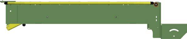

30 E GATE / GAP / 0


31 EEZ GATE 9 " / GAP / 9/ 0 9 ITEM PART NUMBER DESCRIPTION B-00-0 B-00-0 B-00 CONTACT FACTORY PT-0 PT-0 REFLECTOR -.0"DIA,."DIA MTG HOLE TILT SWITCH UNITIZED ZONE CTRL-POL REFLEX TRANSDUCER UNIDRIVE MOTOR CONTROL KNOB - PLASTIC, "DIA, /- THDS ACCUM CHNL - -/"LG REFLECTOR CHNL - -/"LG MTG ANGLE - REFL CHNL,90ABEZ,SPEZ GATE HINGE ASSEMBLY GATE LATCH - -/"LG, DSG K-BRACKET - -/" X " X -/"
32 E MOTOR Connect this end to power supply. This end should be located toward the hinge of the gate to allow connection with power supply. A WITH POWER SUPPLY YELLOW RED YELLOW RED YELLOW BROWN Detail A Scale.: - Switch # set to off (left) POWER SUPPLY PINS - Motor Connection PINS 9 Yellow Wire From Wiring Harness Power Connection From Wiring Harness Ref. No. Part No. Description EB Wiring Harness, Ft Long, with Drops Unidrive Motor Control Unidrive Motor - DC, /" Lg Shaft Tilt Switch - Encapsulated, Non-Mercury E Power Supply - Amps, /0V PH Female Pin Inline Connector Male Pin Inline Connector Standard Conductor Wire - AWG, Red Detail B Scale : Switch # set to off (left) WITHOUT POWER SUPPLY GATE OPERATION: With this configuration when gate is in the up position, the gate will stop, but the power source until will continue to operate. This end should be located toward the hinge of the gate to allow connection with upstream unit. 9 B Use red wire (0.0) to connect motor run (Pin #9) To Pin # on male connector (0.000) DO NOT CONNECT YELLOW WIRE FROM WIRING HARNESS TO TILT SWITCH RED YELLOW RED BROWN RED (0.0) YELLOW Detail C Scale : Power connection from wiring harness RED BROWN FROM WIRING HARNESS
33 E MOTORS Connect this end to power supply. This end should be located toward the hinge of the gate to allow connection with power supply. A B WITH POWER SUPPLY YELLOW RED YELLOW RED YELLOW BROWN Pin 9 Red Wire (0.0) From Pin of Upstream Card Detail A Scale : Detail B Scale : Switch # Set to on (Right) POWER SUPPLY Pin - Motor Connection Pin 9 Yellow Wire From Wiring Harness Pin Red Wire (0.0) To Pin 9 of Downstream Card Power Connection From Wiring Harness Switch # Set to off (Left) Ref. No. Part No. Description EB Wiring Harness, Ft Long, with Drops Unidrive Motor Control Unidrive Motor - DC, /" Lg Shaft Tilt Switch - Encapsulated, Non-Mercury E Power Supply - Amps, /0V PH Female Pin Inline Connector Male Pin Inline Connector Standard Conductor Wire - AWG, Red Detail C Scale : WITHOUT POWER SUPPLY Pins - Motor Connection Pin 9 Red Wire (0.0) To Pin on male connector (0.000) DO NOT CONNECT YELLOW WIRE FROM WIRING HARNESS TO TILT SWITCH Pin Red Wire (0.0) To Pin 9 of Downstream Card C This end should be located toward the hinge of the gate to allow connection with upstream unit Pin 9 Red Wire (0.0) From Pin of Upstream Card E Switch # Set to off (Left) Power Connection from Wiring Harness Detail E Scale : Switch # Set to on (Right) GATE OPERATION: With this configuration when gate is in the up position, the gate will stop, but the power source until will continue to operate. RED 9 D YELLOW RED BROWN 9 From Tilt Switch RED (0.0) To Pin 9 YELLOW RED FROM BROWN WIRING HARNESS Detail D Scale :.
34 E MOTORS Connect this end to power supply. This end should be located toward the hinge of the gate to allow connection with power supply. Detail B Scale :. From Pin to Pin 9 Switch # Set to On (Right) Detail C Scale :. Fron Pin to Pin 9 Switch # Set to On (Right) WITH POWER SUPPLY A 9 YELLOW RED YELLOW YELLOW RED BROWN B Detail A Scale : Switch # Set to Off (Left) Pin 9 Yellow Wire from Wiring Harness 9 C POWER SUPPLY Pins - Motor Connection Pin Red Wire (0.0) To Pin 9 of Downstream Card Power Connection from Wiring Harness Ref. No. Part No. Description EB Wiring Harness, Ft Long, with Drops Unidrive Motor Control Unidrive Motor - DC, /" Lg Shaft Tilt Switch - Encapsulated, Non-Mercury E Power Supply - Amps, /0V PH Female Pin Inline Connector Male Pin Inline Connector Standard Conductor Wire - AWG, Red WITHOUT POWER SUPPLY Pin 9 Red Wire (0.0) To Pin on Male Connector (0.000) Do Not Connect Yellow Wire from Wiring Harness to Tilt Switch Detail D Scale : D YELLOW E RED RED BROWN This end should be located toward the hinge of the gate to allow connection with upstream unit. Pin Red Wire (0.0) To Pin 9 Detail E Not to Scale GATE OPERATION: With this configuration when gate is in the up position, the gate will stop, but the power source until will continue to operate.
35 EZLOGIC ZONES & E MOTOR PER ZONE WIRING DETAIL FOR CARDS MOUNTED TO CLOSE WHEN GATE IS OPEN BLUE YELLOW BROWN Pins - Motor Connection To Controller Power Connection From Wiring Harness SEE ACCUM KIT FOR CONTROLLER ACCUM POWER / LOGIC IN EZLogic controllers will need to be programmed for zone kill using the Genesis software. ACCUM POWER / LOGIC OUT EZLOGIC ZONE & E MOTOR PER ZONE Ref. No. Part No. Description Wiring Harness, ft Lg, with Drops Unidrive Motor Control Unidrive Motor - DC, / LG Shaft Auxiliary Input Cable - Lg Tilt Switch - Encapsulated, Non-Mercury Female Pin Inline Connector Male Pin Inline Connector WIRING DETAIL FOR CARDS Pins - Motor Connection To Controller MOUNTED TO CLOSE WHEN GATE IS OPEN BLUE YELLOW BROWN Power Connection From Wiring Harness SEE ACCUM KIT FOR CONTROLLER ACCUM POWER / LOGIC IN EZLogic controllers will need to be programmed for zone kill using the Genesis software. ACCUM POWER / LOGIC OUT Ref. No. Part No. Description Wiring Harness, ft Lg, with Drop Unidrive Motor Control Unidrive Motor - DC, / LG Shaft Auxiliary Input Cable - Lg Tilt Switch - Encapsulated, Non-Mercury Female Pin Inline Connector Male Pin Inline Connector
36 EZLOGIC ZONE & E MOTOR PER ZONE WIRING DETAIL FOR CARDS Pins - Motor Connection Switch # Set to On (Right) Power Connection From Wiring Harness MOUNTED TO CLOSE WHEN GATE IS OPEN BLUE YELLOW BROWN Pins - Motor Connection Switch # Set to Off (Left) Power Connection From Wiring Harness From EZLogic Controller ACCUM POWER / LOGIC IN SEE ACCUM KIT FOR CONTROLLER EZLogic controllers will need to be programmed for zone kill using the Genesis software. ACCUM POWER / LOGIC OUT EZLOGIC ZONE & E MOTOR PER ZONE Ref. No. Part No. Description Wiring Harness, ft Lg, with Drop Unidrive Motor Control Unidrive Motor - DC, / LG Shaft Auxiliary Input Cable - Lg Tilt Switch - Encapsulated, Non-Mercury Female Pin Inline Connector Male Pin Inline Connector WIRING DETAIL FOR CARDS MOUNTED TO CLOSE WHEN GATE IS OPEN BLUE YELLOW BROWN SEE ACCUM KIT FOR CONTROLLER ACCUM POWER / LOGIC IN Pins - Motor Connection To Controller Power Connection From Wiring Harness EZLogic controllers will need to be programmed for zone kill using the Genesis software. ACCUM POWER / LOGIC OUT Ref. No. Part No. Description Wiring Harness, 0 ft Lg, with Drops Unidrive Motor Control Unidrive Motor - DC, / LG Shaft Auxiliary Input Cable - Lg Tilt Switch - Encapsulated, Non-Mercury Female Pin Inline Connector Male Pin Inline Connector


37 HYTROL CONVEYOR COMPANY, INC. 00 Hytrol Drive Jonesboro, Arkansas EFFECTIVE August 0
Electronic Proportional (EP) Control for Medium Duty Piston Pumps
 Control for Medium Duty Piston Pumps") Electronic Proportional (EP) Control for Medium Duty 72400 Piston Pumps EP Control for Medium Duty 72400 Piston Pumps Table of Contents Introduction........................................................................
Electronic Proportional (EP) Control for Medium Duty 72400 Piston Pumps EP Control for Medium Duty 72400 Piston Pumps Table of Contents Introduction........................................................................
CBM-105FN/FP Circuit Board
 CBM-105FN/FP Circuit Board Features Adjustable acceleration and deceleration time (0 to 2.5s) Stable speed operation Manual or automatic recovery of the thermal overload device One (1) rotary switch to
Electronic Proportional (EP) Control for Heavy Duty Series 2 Piston Pumps Model 33
 Control for Heavy Duty Series 2 Piston Pumps Model 33") Electronic Proportional (EP) Control for Heavy Duty Series 2 Piston Pumps Model 33 Model 39 Model 46 Model 54 Model 64 EP Control for Heavy Duty Series 2 Piston Pumps Table of Contents Introduction........................................................................
Electronic Proportional (EP) Control for Heavy Duty Series 2 Piston Pumps Model 33 Model 39 Model 46 Model 54 Model 64 EP Control for Heavy Duty Series 2 Piston Pumps Table of Contents Introduction........................................................................
GLM SERIES CONTROL Users Manual Rev:
 GLM SERIES CONTROL Users Manual Rev: 808062 Connecting Power Page 2 Motor Terminal Wiring Diagrams Page 3 Getting Started / Setup Page 4 1. Obstruction Detection Devices Page 4 2. Checking Power and Direction
LIPPERTCOMPONENTS, INC.
 LIPPERTCOMPONENTS, INC. SCHWINTEK INWALL SLIDEOUT SYSTEM OPERATION AND SERVICE MANUAL Contents I. Controls 1-1 System components 1 1-1A versions C1 & C2 2 1-2 Motor wiring harness connections 3 1-3 Extend
Electronic Proportional (EP) Control for Heavy Duty Series 0/1 Piston Pumps Model 33 Model 39 Model 46. Model 54 Model 64 Model 76
 Control for Heavy Duty Series 0/1 Piston Pumps Model 33 Model 39 Model 46. Model 54 Model 64 Model 76") Electronic Proportional (EP) Control for Heavy Duty Series 0/1 Piston Pumps Model 33 Model 39 Model 46 Model 54 Model 64 Model 76 Table of Contents Introduction.......................................................
Electronic Proportional (EP) Control for Heavy Duty Series 0/1 Piston Pumps Model 33 Model 39 Model 46 Model 54 Model 64 Model 76 Table of Contents Introduction.......................................................
MD10. Engine Controller. Installation and User Manual for the MD10 Engine Controller. Full Version
 MD10 Engine Controller Installation and User Manual for the MD10 Engine Controller. Full Version File: MartinMD10rev1.4.doc May 16, 2002 2 READ MANUAL BEFORE INSTALLING UNIT Receipt of shipment and warranty
XR Conveyor Maintenance Guide
 XR Conveyor Maintenance Guide EN-0035 Rev. A XR Conveyor Maintenance Guide www.qdraw.com Table of Contents 05/20/2009 Overview Page 3 XR Conveyor Assembly Page 4 General Information Exploded View of an
CONTROL FEATURES AVAILABLE OPTIONS
 Vari Speed A2000 TABLE OF CONTENTS Control Features Options Application Data Operating Condition s Control Ratings Chart Mounting Dimensions Installation and Wiring Typical Wiring Diagram Schematic (Block
EB Conveyor Maintenance Guide
 EB Conveyor Maintenance Guide EN-0037 Rev A EB Conveyor Maintenance Guide www.qdraw.com Table of Contents Overview Page 3 Exploded View Of A Standard EB Conveyor Page 4 Preventative Maintenance Page 5
Installation, Operation and Maintenance Manual
 Document 47681 Vari-Green Motor and Controls Installation, Operation and Maintenance Manual Please read and save these instructions for future reference. Read carefully before attempting to assemble, install,
MANUAL TROUBLESHOOTING. ECM Motor. ECM / ECM-DX Series. v100 Issue Date: 08/15/ Price Industries Limited. All rights reserved.
 MANUAL ECM Motor ECM / ECM-DX Series v100 Issue Date: 08/15/17 2017 Price Industries Limited. All rights reserved. ECM MOTOR TABLE OF CONTENTS ECM Motor Background...1 ECM Motor Power and Control Connectors...2
Eaton Electronic Proportional (EP) Control for Medium Duty Piston Pumps
 Control for Medium Duty Piston Pumps") Eaton Electronic Proportional (EP) Control for Medium Duty 72400 Piston Pumps Table of Contents Introduction....................................................... 3 Identification of Components.........................................
Eaton Electronic Proportional (EP) Control for Medium Duty 72400 Piston Pumps Table of Contents Introduction....................................................... 3 Identification of Components.........................................
Installation, Operation and Maintenance Manual
 Document 47681 Vari-Green Motor and Controls Installation, Operation and Maintenance Manual Please read and save these instructions for future reference. Read carefully before attempting to assemble, install,
User Manual. T6 Tachometer. Online: Telephone: P.O. Box St. Petersburg, Florida 33736
 User Manual T6 Tachometer Online: www.phareselectronics.com Telephone: 727-623-0894 P.O. Box 67251 St. Petersburg, Florida 33736 Table of Contents Overview... 1 Description... 1 Wiring... 1 T6 Tachometer
Boston Gear Ratiotrol DC Motor Speed Control
 Boston Gear Ratiotrol DC Motor Speed Control P-3049-BG Doc. No. 83721 Installation and Operation RG1 and RG2 Models 1/6-1 HP a division of Altra Industrial Motion Contents General Information.....................
Installation, Operation and Maintenance Manual
 Document 473681 Vari-Green Motor and Controls Installation, Operation and Maintenance Manual Please read and save these instructions for future reference. Read carefully before attempting to assemble,
User Manual JS-ICON. 624 ARCH Dimmer Rack. JOHNSON SYSTEMS INC. Spring
 User Manual JS-ICON 624 ARCH Dimmer Rack JOHNSON SYSTEMS INC. Spring 2007 2002161 Table of Contents JS-ICON 624 DMX JS-ICON 624 CC 6-2.4kW Dimming Strip JS-ICON 624 ND 6-2.4kW Relay Strip Introduction...3
Installation, Operation and Maintenance Manual
 Document 473681 Vari-Green Motor and Controls Installation, Operation and Maintenance Manual Please read and save these instructions for future reference. Read carefully before attempting to assemble,
Fincor DC Drives. Flexible & Powerful TYPICAL APPLICATIONS. Conveyor Rugged. Extruder Reliable. Conveyor Simple. Mixer Flexible
 DC Drives Flexible & Powerful single-phase DC drives provide a complete family solution from the compact Series 2120 chassis drive to the powerful Series 2230 and it s feature rich application specific
G213V STEP MOTOR DRIVE REV 7: March 25, 2011
 Thank you for purchasing the G213V drive. The G213V is part of Geckodrive s new generation of CPLD-based microstep drives. It has short-circuit protection for the motor outputs, over-voltage and under-voltage
DC Variable Speed Drive Panel
 DC Variable Speed Drive Panel Installation, Operation & Maintenance Instruction Manual Bulletin #: CC-IOM-0103-D Manufacturers of Quality Pumps, Controls and Systems ENGINEERED PUMP OPERATIONS 2883 Brighton
GENERAL REQUIREMENTS:
 Installation & Service Manual Slim Rack Bunk Lift System with Control Box 1510000199 or 1510000260 Content Copyright Power Gear Issued: January 2013 # 3010002675, Rev. 0D Installation and Service Manual
SERIES 700/700E FACTORY KEYLESS UPGRADE INSTALLATION MANUAL
 SERIES 700/700E FACTORY KEYLESS UPGRADE INSTALLATION MANUAL Items Supplied with the System: Installation Instructions: Main unit 1. Mounting the module: Plug In LED Mount the module in a suitable location
Motor. Document # Vari-Green Motor and Controls. Table of Contents. Features, Operation, Wiring and Troubleshooting
 Document #473681 Vari-Green Motor and Controls Installation, Operation and Maintenance Manual Please read and save these instructions for future reference. Read carefully before attempting to assemble,
Troubleshooting Bosch Proportional Valves
 Troubleshooting Bosch Proportional Valves An Informative Webinar Developed by GPM Hydraulic Consulting, Inc. Instructed By Copyright, 2009 GPM Hydraulic Consulting, Inc. TABLE OF CONTENTS Bosch Valves
GENERAL REQUIREMENTS:
 Installation & Service Manual Slim Rack Bunk Lift System with Control Box 1510000199 or 1510000260 Content Copyright Power Gear Issued: January 2013 # 3010002675, Rev. 0D Installation and Service Manual
DuraWatt DS12VD 140-Watt DC-DC 12 Volt Power Supply Short Form User Manual Version 1.0. Table of Contents
 DuraWatt DS12VD 140-Watt DC-DC 12 Volt Power Short Form User Manual Version 1.0 Table of Contents 1. Getting Started...1 1.1. Introduction...1 1.2. Product Photo...2 1.3. Block Diagram...2 1.4. Included
NOTE. Installation and Service Manual Dual Planetary Gearmotor Slim Rack Slide Out System
 Installation & Service Manual Slim Rack In-Wall Slide Out System Control Box Part Number 1510000199 Content Copyright LCI/Power Gear Issued: December 2014 #3010002588, Rev. 0E Installation and Service
USERS GUIDE LO-21U LOCKOUT RELAY
 USERS GUIDE LO-21U LOCKOUT RELAY PRODUCT DESCRIPTION The LO-21U (PN: 10LO21U) is a micro-processed lock out module designed to operate on swing door applications with BEA s Bodyguard or DK-12 overhead
XENON POWER SUPPLY 4000 Watt Gladiator IV
 XENON POWER SUPPLY 4000 Watt Gladiator IV 220 Volt Equipment Type 62-00049 Rev. February 2003 STRONG INTERNATIONAL a division of Ballantyne of Omaha, Inc. 4350 McKinley Street Omaha, Nebraska 68112 USA
ACC Series Power Conditioner OPERATION & INSTALLATION MANUAL
 ACC Series Power Conditioner OPERATION & INSTALLATION MANUAL PHASETEC digital power conditioners are designed to safely operate electrical equipment in the harshest power quality environments. With a wide
G203V / G213V MANUAL STEP MOTOR DRIVE
 G203V / G213V MANUAL STEP MOTOR DRIVE PRODUCT DIMENSIONS PHYSICAL AND ELECTRICAL RATINGS Minimum Maximum Units Supply Voltage 18 80 VDC Motor Current 0 7 A Power Dissipation 1 13 W Short Circuit Trip 10
BLDC SPEED CONTROL INSTRUCTION MANUAL Line voltage Brushless DC control
 BLDC SPEED CONTROL INSTRUCTION MANUAL Line voltage Brushless DC control Phone 712.722.4135 groschopp.com 420 15th St NE, Sioux Center, IA 51250 Toll-Free 800.829.4135 Email sales@groschopp.com FAX 712.722.1445
Maintenance Manual 13 AMPERE POWER SUPPLY 19A704647P1-P3. Mobile Communications LBI-31801C
 C Mobile Communications 13 AMPERE POWER SUPPLY 19A704647P1-P3 CAUTION THESE SERVICING INSTRUCTIONS ARE FOR USE BY QUALI- FIED PERSONNEL ONLY. TO AVOID ELECTRIC SHOCK DO NOT PERFORM ANY SERVICING OTHER
M T E C o r p o r a t i o n MATRIX FILTER. SERIES B Volts, 50HZ USER MANUAL PART NO. INSTR REL MTE Corporation
 M T E C o r p o r a t i o n MATRIX FILTER SERIES B 380-415 Volts, 50HZ USER MANUAL PART NO. INSTR - 015 REL. 060628 2006 MTE Corporation IMPORTANT USER INFORMATION NOTICE The MTE Corporation Matrix Filter
Owner s Manual Dual Planetary Gearmotor Slim Rack Slide Out System
 Owner s Manual Slim Rack In Wall Slide Out System Control Box Part Number 1510000199 Content Copyright LCI/PowerGear Issued: December 2014 #3010002679, Rev. 0C Owner s Manual Dual Planetary Gearmotor Slim
TA-05/C. Instruction and Operation Manual. valid for art.-no.: F-TA-05/C-ISO. (start at modification No. 1601)
") Instruction and Operation Manual valid for art.-no.: 10091 F-TA-05/C-ISO (start at modification No. 1601) valid for art.-no.: 10092 F-TA-05/C-Sh (start at modification No. 1601) CAUTION: As with any form
Instruction and Operation Manual valid for art.-no.: 10091 F-TA-05/C-ISO (start at modification No. 1601) valid for art.-no.: 10092 F-TA-05/C-Sh (start at modification No. 1601) CAUTION: As with any form
Operating & Installation Manual
 Operating & Installation Manual Variable Speed Controller for DC Motors Up To /2 hp 5 VAC, 50/60 Hz, Single-Phase Input Models: 7-2 & 7-22 85-26 Rev. E Table of Contents.0 Safety Considerations...................................................
IV. PROOF OF PURCHASE: A warranty claim must be accompanied by proof of the date of purchase.
 PD9100 / 9200 SERIES POWER CONVERTER OWNERS MANUAL PROGRESSIVE DYNAMICS, INC. POWER CONVERTER LIMITED WARRANTY I. LIMITED WARRANTY: Progressive Dynamics, Inc. warrants its power converter to be free from
Built-in ZPA Logic Hybrid Driver Card No. HB-508S
 Built-in ZPA Logic Hybrid Driver Card No. HB-508S HB-508S is the new generation of Built-in ZPA Logic Hybrid Driver Card. The HB-508S has both slug (train) tote release mode and singulated tote release
Installation & Service Manual
 Installation & Service Manual for M² Sync Slideout Control Box #1510000122 CONTENTS Introduction Installation Installation Problems Program Mode Operation Mode Preventative Maintenance Fault Diagnostics
APOLLO Gate Operators, Inc.
 APOLLO Gate Operators, Inc. Model 3500ETL/3600ETL Commercial Swing Gate Operator INSTALLATION MANUAL 01/08 CONTENTS IMPORTANT SAFETY INSTRUCTIONS. 3 Applications... 4 Pre-Installation Checklist... 5 Parts
GS10 Series MODELS: GS10 GS10-R NEMA 4X SCR MOTOR CONTROLS. User s Manual
 GS10 Series MODELS: GS10 GS10-R NEMA 4X SCR MOTOR CONTROLS User s Manual Safety Warnings SHOCK HAZARD AVOID HEAT KEEP DRY AVOID VIBRATION This symbol denotes an important safety tip or warning. Please
Electronic Dynamo Regulator INSTRUCTION MANUAL. COPYRIGHT 2014 CLOVER SYSTEMS All Rights Reserved
 DRM TM DRM-HP TM Electronic Dynamo Regulator INSTRUCTION MANUAL COPYRIGHT 2014 CLOVER SYSTEMS All Rights Reserved INTRODUCTION The Clover Systems DRM is a state-of-the art all-electronic voltage and current
17429X.00 SERIES MODELS:
 LEESON ELECTRIC MOTORS, GEARMOTORS AND DRIVES R User s Manual 17429X.00 SERIES MODELS: 174298.00 174299.00 PWM REGENERATIVE DC TO DC DRIVES II Table of Contents 17429X.00 Drives...............................................................
1332 TROUBLESHOOTING GUIDE. Remarks: If this function is not appropriate for the application, it can be eliminated by turning off DSWl, switch 3.
 1332 TROUBLESHOOTING GUIDE Maintenance The Drive is convection or fan cooled by air flowing through the heat sink slots. The slots must never be allowed to become obstructed with dirt or foreign matter.
1.0 Features and Description
 1.0 Features and Description The is an intelligent actuator designed for precise control of quarter turn valves and dampers. Using stepper motor technology, the SmartStep proportionally positions valves
Microroller Driver Module For use with Holjeron Microroller
 Microroller Driver Module For use with Holjeron Microroller ZLD-6510-5 0617 Description The Microroller Driver Module connects directly to a Holjeron Microroller motorized roller. The Microroller Driver
Continuing Education Course #206 Introduction to Designing Machine Control Systems Part 2
 1 of 5 Continuing Education Course #206 Introduction to Designing Machine Control Systems Part 2 1. Continuing to answer the following questions indicates that you understands that the presented material
Part Number Analog Style 15 PSI Fuel/Boost Pressure Gauge. NOTE: Faceplate Configuration Instructions Included on Separate Sheet
 Part Number 30-5144 Analog Style 15 PSI Fuel/Boost Pressure Gauge NOTE: Faceplate Configuration Instructions Included on Separate Sheet AEM Oil/Fuel Pressure Gauge Parts 1 x 35-5144 Pressure Gauge Assembly
APOLLO Gate Operators, Inc.
 APOLLO Gate Operators, Inc. Model 7200ETL Post Mounted Residential & Heavy Duty Commercial Slide Gate Operator INSTALLATION MANUAL 04/11 CONTENTS IMPORTANT SAFETY INSTRUCTIONS... 3 Applications... 4 Pre-Installation
User Manual. Solar Charge Controller 3KW
 User Manual Solar Charge Controller 3KW 1 CONTENTS 1 ABOUT THIS MANUAL... 3 1.1 Purpose... 3 1.2 Scope... 3 1.3 SAFETY INSTRUCTIONS... 3 2 INTRODUCTION... 4 2.1 Features... 4 2.2 Product Overview... 5
Service Manual. Extractor Model XR28QP. For The. For: Troubleshooting Adjustments
 Service Manual For The X Ride 28 Rider Extractor Model XR28QP For: Training Troubleshooting Adjustments Contents 1 Cautions ------------------------------------------------------------------------------
MINE CHARGER INSTALLATION AND OPERATION MANUAL MODEL NUMBERS: MSP MSQ MSR MSS
 MINE CHARGER INSTALLATION AND OPERATION MANUAL MODEL NUMBERS: MSP MSQ MSR MSS Sec# Table of Contents Pg# 1 INSTALLATION 1.1 Receiving 1 1.2 Location 1 1.3 Line Voltage Adjustments 2 1.4 A.C. Service Requirements
27.6 Vdc 1 Amp Switch Mode Power Supply for Fire EN54-4:1997 +A1 +A2
 1 27.6 Vdc 1 Amp Switch Mode Power Supply for Fire EN54-4:1997 +A1 +A2 STX2401-C STX2401-T FEATURES 0843-CPR-0213 14 Elmdene International Ltd Tel: +44(0)23 9269 6638 3 Keel Close, Interchange Park, Fax:
SB SWITCH CONTROL BOX
 Carson Manufacturing Co., Inc. 5451 North Rural Street Indianapolis, IN 462 Phone: (888) 577-6877 Fax: (317) 254-2667 www.carsonsirens.com SB-008-25 SWITCH CONTROL BOX INSTALLATION AND OPERATING INSTRUCTIONS
SALDET SALES & SERVICE, INC. CLINTON TOWNSHIP, MICHIGAN
 Form 1254 BRAKETRON Electronic Motor Brake Instructions SALDET SALES & SERVICE, INC. CLINTON TOWNSHIP, MICHIGAN TABLE OF CONTENTS SECTION TITLE PAGE I. Introduction 1 II. Specifications 1 III. Principles
Installation and Service Manual M² Sync Room Slideout System without Room Lock Connectors on Control Box
 Installation & Service Manual M² Sync Room Slideout System w/o Room Locks: for Slideout Control Box# 1510000143 and 1510000198 Figure 1 01/13 Power Gear #3010002088 Rev. 0C Installation and Service Manual
Microroller Driver Module For use with Holjeron Microroller
 ZLD-6510-6 0318 Description The Microroller Driver Module connects directly to a Holjeron Microroller motorized roller. The Microroller Driver Module uses microprocessor-based commutation of the brushless
User s Manual. Automatic Switch-Mode Battery Charger
 User s Manual Automatic Switch-Mode Battery Charger IMPORTANT Read, understand, and follow these safety rules and operating instructions before using this battery charger. Only authorized and trained service
Dycon D2430 EN54-4 Fire Alarm Power Supply Series
 Dycon D2430 EN54-4 Fire Alarm Power Supply Series Technical Description Installation and Operating Manual Construction Product Regulation 0359-CPR-00434 Page 1 of 14 Contents 1. General... 3 1.1 Product
INSTALLATION INSTRUCTIONS
 INSTALLATION INSTRUCTIONS Universal Air Series!! NOTE!! Covers the following model: 6000 Series 85-0100B-AZ Rev 0 5/07 To ensure that the system is installed properly, provide your electrician with these
Rover Series. Rover 20A 40A Maximum Power Point Tracking Solar Charge Controller
 Rover Series Rover 20A 40A Maximum Power Point Tracking Solar Charge Controller 0 2775 E. Philadelphia St., Ontario, CA 91761 1-800-330-8678 Version 1.5 Important Safety Instructions Please save these
MDCKB VAC, 8A Brushless Controller. User s Guide E. Landon Drive Anaheim, CA
 MDCKB1-120081-01 110VAC, 8A Brushless Controller User s Guide A N A H E I M A U T O M A T I O N 4985 E. Landon Drive Anaheim, CA 92807 e-mail: info@anaheimautomation.com (714) 992-6990 fax: (714) 992-0471
AUTO-PUMP 12V HP-VER FOR VERTICAL MOUNT ONLY MODEL #: V-HP-VER 12VDC HIGH OUTPUT AIR COMPRESSOR SYSTEM INSTRUCTION MANUAL
 INSTRUCTION MANUAL AUTO-PUMP 12V HP-VER 12VDC HIGH OUTPUT AIR COMPRESSOR SYSTEM FOR VERTICAL MOUNT ONLY MODEL #: 091-9-12V-HP-VER INPUT :10-15 volt, 11 amp OUTPUT :125 PSI MAXIMUM File: 091-9-12V-HP-VER_revA
Application Engineering
 Application Engineering March 2011 Copeland Digital Compressor Controller Introduction The Digital Compressor Controller is the electronics interface between the Copeland Scroll Digital compressor or the
WDC CONTROL SERIES. Instruction Manual. Variable Speed DC Control
 WDC CONTROL SERIES Instruction Manual Variable Speed DC Control P.O. Box 307 1 Grove Street - Suite 201B Pittsford, NY 14534 Phone: (800) 808-2131 Fax: (800) 711-1616 www.worldwideelectric.net TABLE OF
Model: ACP-12 AUTO COMPRESSOR PUMP SYSTEM 12 VDC INSTALLATION & OPERATION MANUAL. Phone:
 INSTALLATION & OPERATION MANUAL Model: ACP-12 AUTO COMPRESSOR PUMP SYSTEM 12 VDC Manual Part # M-ACP12 Revised 10/27/08 KK 1 INTRODUCTION The Auto Compressor Pump system is a compact 12 VDC electric motor
ADVR-12. Hybrid Universal Analog Digital Voltage Regulator Operation Manual
 ADVR-12 Hybrid Universal Analog Digital Voltage Regulator Operation Manual Adapter plugs for Digital Regulator Self Excited Automatic Voltage Regulator For use in Brushless PMG and Auxiliary Winding 4501
Type ABL-3906C Low-Voltage Brushless DC Motor Controls (IP-00)
") Instructions for Installation and Operation Type ABL-3906C Low-Voltage Brushless DC Motor Controls (IP-00) Model 3908 12 VDC (60 commutation) Model 3909 24 VDC (60 commutation) Model 3919 24 VDC (120 commutation)
Instructions for Installation and Operation Type ABL-3906C Low-Voltage Brushless DC Motor Controls (IP-00) Model 3908 12 VDC (60 commutation) Model 3909 24 VDC (60 commutation) Model 3919 24 VDC (120 commutation)
Boston Gear Ratiotrol
 Boston Gear Ratiotrol DC Motor Speed Control Installation and Operation Doc. No. 3721 RG1 and RG2 Models 1/6-1 HP GENERAL INFORMATION DESCRIPTION Series RG Controllers statically convert single-phase AC
AVR Hybrid Universal Analog Digital Voltage Regulator Operation Manual
 AVR 63-12 Hybrid Universal Analog Digital Voltage Regulator Operation Manual Self Excited Automatic Voltage Regulator For use in Brushless PMG and Auxiliary Winding 1. SUMMARY The AVR 63-12 is a totally
Power Distribution System User s Manual. Model: PDS-100
 Power Distribution System User s Manual Model: PDS-0 Section Page Product Overview... 1 I) General Information... 2 II) Important Safety Information... 2 III) Installation... 3 A) Materials Provided...
CALTRAP INSTALLATION AND OPERATIONS MANUAL
 INSTALLATION AND OPERATIONS MANUAL NOTE Please read this entire installation and operations manual before energizing the. Safety Considerations: Installing and servicing capacitor equipment can be hazardous.
PL900 ILLUMINATOR. Fiber-Lite. Operation Manual. Setup. Fiber Optic Connection A PRODUCT OF DOLAN-JENNER INDUSTRIES. Voltage Selection:
 PL900 ILLUMINATOR A PRODUCT OF DOLAN-JENNER INDUSTRIES Setup Voltage Selection: Operation Manual Read and review the instructions on the label covering the power entry module and the instructions in this
Installation and Service Manual M² Sync Room Slideout System without Room Lock Connectors on Control Box
 Installation & Service Manual M² Sync Room Slideout System w/o Room Locks: for Slideout Control Box# 1510000143 and 1510000198 Figure 1 01/13 Power Gear #3010002088 Rev. 0C Installation and Service Manual
MODEL 422 Submersible Pump Controller
 MODEL 422 Submersible Pump Controller Monitors True Motor Power (volts x current x power factor) Detects Motor Overload or Underload Operates on 120 or 240VAC, Single-phase or 3-phase Built-in Trip and
BLDC SPEED CONTROL INSTRUCTION MANUAL Low voltage Brushless DC control
 BLDC SPEED CONTROL INSTRUCTION MANUAL Low voltage Brushless DC control Phone 712.722.4135 groschopp.com 420 15th St NE, Sioux Center, IA 51250 Toll-Free 800.829.4135 Email sales@groschopp.com FAX 712.722.1445
BE 1 BODY ELECTRICAL SYSTEM
 BE1 BE2 GENERAL INFORMATION Wiring color code Wire colors are indicated by an alphabetical code. B = Black L = Blue R = Red BR = Brown LG = Light Green V = Violet G = Green O = Orange W = White GR = Gray
CBC-802 Plug-In Clutch/Brake Control with Solid State Switching
 CBC-02 Plug-In Clutch/Brake Control with Solid State Switching P-2104-WE 19-054 Service & Installation Instructions An Altra Industrial Motion Company Brake (Red) and clutch (Green) indicator lights When
Application Engineering
 Application Engineering February, 2009 Copeland Digital Compressor Controller Introduction The Digital Compressor Controller is the electronics interface between the Copeland Scroll Digital Compressor
SE-3SCR-LM MANUAL MOTOR LOAD MANAGER
 3714 Kinnear Place Saskatoon, SK Canada S7P 0A6 Ph: (306) 373-5505 Fx: (306) 374-2245 www.littelfuse.com/relayscontrols SE-3SCR-LM MANUAL MOTOR LOAD MANAGER MARCH 5, 2013 REVISION 4 MOTOR LOAD MANAGER
Matrix APAX. 380V-415V 50Hz TECHNICAL REFERENCE MANUAL
 Matrix APAX 380V-415V 50Hz TECHNICAL REFERENCE MANUAL WARNING High Voltage! Only a qualified electrician can carry out the electrical installation of this filter. Quick Reference ❶ Performance Data Pages
A flexible, reliable and affordable drive for 1/4 through 2 HP DC applications
 A flexible, reliable and affordable drive for 1/4 through 2 HP DC applications DC2 drives combine application flexibility, compact size and reliability into an affordable adjustable speed package that
PM500. Voltage Regulator User Manual. A Regal Brand. Scan here for other languages.
 PM500 Voltage Regulator User Manual A Regal Brand Scan here for other languages. Introduction The PM500 is an encapsulated electronic voltage regulator intended for use with Marathon Generators PMG system.
Electronic Dynamo Regulator INSTRUCTION MANUAL. COPYRIGHT 2014 CLOVER SYSTEMS All Rights Reserved
 DRM TM DRM-HP TM Electronic Dynamo Regulator INSTRUCTION MANUAL COPYRIGHT 2014 CLOVER SYSTEMS All Rights Reserved INTRODUCTION The Clover Systems DRM is a state-of-the art all-electronic voltage and current
2122H. Arm Field Arm Field 1/8-1/ / /8-1/ / / /
 Non-Regen Drives Non-regenerative drives are typically used on applications which primarily motor in one direction and stopping is achieved through friction or infrequent use of a dynamic braking resistor.
Setup and Programming Manual
 Microprocessor and Handy Terminal Setup and Programming Manual Versions U04 to U19 for Sliding Door Systems P/N 159000 Rev 7-2-07 The manufacturer, NABCO Entrances, Inc. suggests that this manual be given
ACCESSORY KIT INSTALLATION INSTRUCTIONS
 ACCESSORY KIT INSTALLATION INSTRUCTIONS Low Ambient Accessory For Air Cooled Split-System Air Conditioners YD360/480/600, YJ-30/-40/-50 and J30/40/50 YD Models 642546-UAI-A-080 GENERAL Standard operation
OnCommand Troubleshooting Guide Hayward Industries
 OnCommand Troubleshooting Guide 2010 Hayward Industries Table of Contents Safety Precautions Page 1 Overview Pages 2-5 Software Troubleshooting Page 6 Local Display Pages 7-8 Relays Pages 9-10 Heaters
HYPPOETL HYPPO DUALETL 12 VOLT DC Swing Gate Operator
 HYPPOETL HYPPO DUALETL 12 VOLT DC Swing Gate Operator Manufactured by NICE SpA INSTALLATION MANUAL 08/10 CONTENTS IMPORTANT SAFETY INSTRUCTIONS... 3 Applications...... 4 Pre-Installation Checklist... 5
DUAL SWIVEL REEL OPERATING INSTRUCTIONS
 DUAL SWIVEL REEL OPERATING INSTRUCTIONS MODELS 100 & 1000 SERIES RAPID-AIR CORPORATION 4601 KISHWAUKEE ST. ROCKFORD, IL 61109-2925 Phone: (815) 397-2578 Fax: (815) 398-3887 Web Site: www.rapidair.com OPERATING
DIN Rail UPS Model: DIN-UPS Installation/Operation Manual
 DIN Rail UPS Model: DIN-UPS 24-10 Installation/Operation Manual Table of Contents Section Page Section Page Quick Start 2 1) General Information 4 Materials Provided 4 Optional Equipment 4 2) Safety Information
CB-005N Circuit Board
 CB-005N Circuit Board Provides Thermal Protection for board and motor Built-in current limiter Error Output signal for self diagnosis Dynamic brake control Variable speed (0% - 100%) by onboard potentiometer
ACCUSENSE CHARGE SERIES ON/OFF BOARD FULLY AUTOMATIC BATTERY CHARGER
 ACCUSENSE CHARGE SERIES ON/OFF BOARD FULLY AUTOMATIC BATTERY CHARGER SPECIFICATIONS: *Photo for reference only* Part number 8890439 Mode Select: Selects Battery Type Refer to Section 6. IMPORTANT: READ
12 Series Linear Actuators. Operation & Maintenance Manual, Analog Positioner Installation
 12 Series Linear Actuators Operation & Maintenance Manual, Analog Positioner Installation 6810 POWERLINE DR.-FLORENCE, KY. 41042 - TELEPHONE 859-727-7890, TOLL FREE 1-800-662-9424 FAX. 859-727-4070, E-MAIL:
MDCKB VAC, 8A Brushless Controller. User s Guide E. Landon Drive Anaheim, CA
 MDCKB1-120081 120VAC, 8A Brushless Controller User s Guide A N A H E I M A U T O M A T I O N 4985 E. Landon Drive Anaheim, CA 92807 e-mail: info@anaheimautomation.com (714) 992-6990 fax: (714) 992-0471
CABINET REEL OPERATING INSTRUCTIONS
 CABINET REEL OPERATING INSTRUCTIONS MODELS 15, 25, 40 & 60 SERIES RAPID-AIR CORPORATION 4601 KISHWAUKEE ST. ROCKFORD, IL 61109-2925 Phone: (815) 397-2578 Fax: (815) 398-3887 Web Site: www.rapidair.com
TRIPS AND FAULT FINDING
 WWW.SDS.LTD.UK 0117 9381800 Trips and Fault Finding Chapter 6 6-1 TRIPS AND FAULT FINDING Trips What Happens when a Trip Occurs When a trip occurs, the drive s power stage is immediately disabled causing