INSTALLATION MANUAL 86/BRZ ZN6/ZC6
|
|
|
- Sabina Paul
- 6 years ago
- Views:
Transcription
1 INSTALLATION MANUAL 86/BRZ ZN6/ZC6
2 Thank you for purchasing this product. General Information This manual has been prepared to provide owners important information and data upon installing and using this product. Please read and utilize this manual fully to ensure your safety before starting your work. This manual is best to be kept in vehicles for constant reference. Product information and mountable vehicle Vehicle Name: TOYOTA 86/SUBARU BRZ Vehicle Model: ZN6/ZC6 Engine: FA20 Transmission: TOYOTA 86 MT AT / SUBARU BRZ MT AT Model Year: 2012/4~(ZN6) / 2012/3~ (ZC6) Product Name: BLITZ TURBO SYSTEM 86/BRZ Product Number: TUNERS KIT W/O CATA TUNERS KIT STARTUP KIT FULL KIT Since January 2014, Products beside TUNERS KIT W/O CATA are compatible for TOYOTA 86(ZN6) MT and SUBARU BRZ MT. Car fitting list (since January 2014) Product\Vehicle type TUNERS KIT W/O CATA TUNERS KIT STARTUP KIT FULL KIT 86 (ZN6) MT AT BRZ(ZC6) MT AT Contact us For information, please contact us through fax or phone as stated as below: Contact name: Blitz Support Center TEL: Adress:4-7-6 Shinmachi, Nishitokyo-City, Tokyo Japan FAX: Precaution This product is assembled from the parts and sub-parts as listed below. If any shortage or defected of goods is found, please contact our support center. Do not drop this product. Do not use excessive force while installing. These will lead to exhaustion or oil leakage and product might not be able to perform perfectly. Genuine parts are reused besides gasket with kit. If the reuse gasket is badly damage or deteriorated, it is advice to prepare a new one. Oil from engine will be extracted in the installment process. Therefore, it is advice to prepare fresh oil beforehand. Please use boost meter to check the condition of the turbocharger.
3 Important Notice This product is made to fit normal vehicles. However, there is possibility for this product to not fit vehicles that has been installed with conventional parts (besides genuine parts), or with accident history. The second catalyzer is a genuine product with certification and approval of exhaust gas. Replacement of second catalyzer to other catalyzer might be non-compliant for vehicle inspection. Re-setting of ECU such as pressure adjustment of booster, fuel and ignition settings is necessary upon usage of this product. All installment work must be operating when vehicle is completely stopped and parked on a flat compound when working. Engine must be completely cool down before installment work begins. All installment work must be operating according to the steps written on the manual handbook provided by the manufacturer. Regular maintenance is necessary after installment, be sure to tighten all loosen parts. Our Company will not be responsible for any installment of this product on vehicle other than the notation car model. Our Company will not be responsible for any side effects or damage of other parts after installment of this product. When driving on public roads, please abide by the law and regulations. Installment Cautions This product must be clean thoroughly before installment. Check for any burrs or debris, be sure to clean it all. Be caution of foreign matters getting inside of the center core. Must read for all installer. This manual must be return to customer after installation. Must read before installment. A new genuine part must be replaced if any degradation of hose or bands in genuine parts is found. Thorough Inspection of the reuse genuine gasket must be perform and must be replaced with a new genuine gasket if any defection found. Warning Injuries upon installment To prevent any injuries during installment of this product, it is advised to send your vehicle to professionals with equipped workshops for installment. Genuine products as above refer to vehicle manufactures standard installment products.
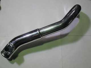
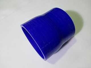
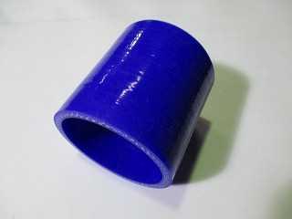
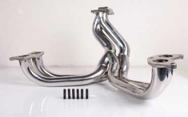
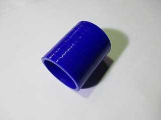
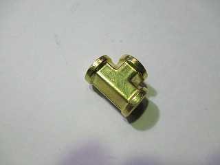
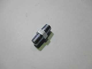
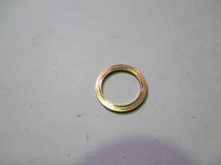
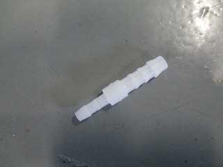
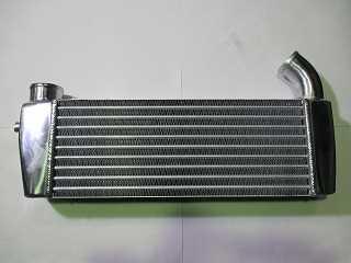
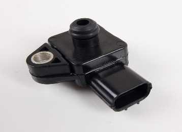
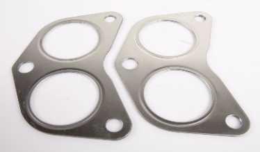
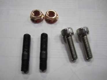
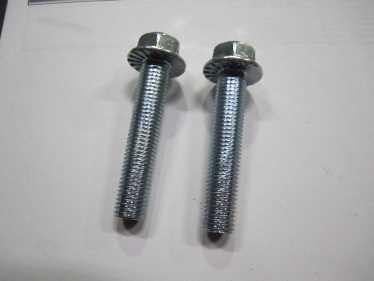
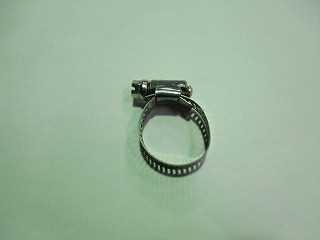
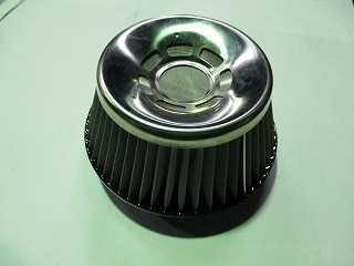
4 Parts List: Before beginning installation, verify that all parts are included in the kit. Report us any shortages or damaged parts immediately. Item Number Description 1 Turbo Charger Assembly(B06-380R) 1 2 Exhaust manifold (Header) 1 3 Turbo down pipe(tuners KIT is without the catalyzer) 1 4 Heat shield of exhaust housing 1 5 Suction pipe(from air cleaner to turbo charger) 1 6 Intake pipe No1 1 7 Intake pipe No angle elbow fitting 1 9 Silicon hose No1(φ60 L=50mm) 2 10 Silicon hose No2(φ50 L=70mm) 2 11 Silicon hose No3(φ60 L=70mm) 1 12 Silicon hose No4(Reducer hose φ75-φ70 L=80mm) 1 13 Blow by gas hose(φ12 L=150mm) 1 14 Joint Pipe for blow by gas hose(φ12 L=52mm) 1 15 Turbo Charger mounting stay No Turbo Charger mounting stay No Collar of Turbo Charger mounting stay(φ20 H=15mm) 2 18 Mounting stay No1 for intercooler (RH) 1 19 Mounting stay No2 for intercooler (LH upside) 1 20 Mounting stay No3 for intercooler (LH downside) 1 21 Oil drain pipe(φ16 For welding process) 1 22 Oil outlet pipe for turbocharger 1 23 Gasket for turbocharger oil outlet 1 24 Oil drain hose(φ16 L=500mm) 1 25 Oil feed hose (Stainless steel) 1 26 Heat shield S(φ15 L=600mm) 1 27 Heat shield M(φ23 L=500mm) 1 28 Straight union fitting way union fitting angle union fitting 1 31 Banjo fitting 1 32 Banjo bolt(m10 P1.25) 1 33 Cu washer(10φ t=1.0mm) 2 34 φ4 silicon tube (L=500mm) 1 35 φ6 silicon tube (L=500mm) 1 36 φ4-φ6 union fitting 1 37 Hose clamp No1(φ15-22mm) 2 38 Hose clamp No2(φ18-32mm) 2 39 Hose clamp No3(φ46-70mm) 4 40 Hose clamp No4(φ57-76mm) 6 41 Hose clamp No5(φ59-82mm) 1 42 Hose clamp No6(φ71-95mm) 1 43 Turbine In Gasket 1 44 Turbine Out Gasket 1 45 Exhaust Manifold Gasket 2 46 Gasket for downpipe 1 47 MAP sensor 1 48 Ceramic fiber turbo wrap (heat shield wrap) 1 49 Inter cooler assembly 1 50 Air cleaner attachment 1 51 Air cleaner core(suspower C4 core) 1 M8 Stud bolt (for turbine housing IN) 2 52 M8 25mmHex socket head cap screw(for turbine housing IN) 2 M8 Nut with flange (for Turbine In) 2 53 M6 16mm Hex flange bolt(for Pipe Oil Out) 2 Qty
5 54 M10 50mm Hex flange bolt(for turbine mounting stay) 2 55 M8 12mm Hex flange bolt (for turbine mounting stay) 2 M8 20mm Hex flange bolt(for turbine mounting stay) 2 M8 Stud bolt (for turbine housing out) 2 56 M8 25mm Hex socket head cap screw(for turbine housing out) 3 M8 Nut with flange (for turbine housing out) 2 57 M10 35mm Hex flange bolt(for down pipe) 2 M10 Nut with flange(for down pipe) 2 58 M6 12mm Hex flange bolt(for heat shield) 3 59 M4 8mm pan head screw(for mass flow sensor) 2 M6 Nut with flange(for intercooler mounting) 3 60 M6 20mm Hex flange bolt(for intercooler mounting) 3 M8 12mm Hex flange bolt(for intercooler mounting) 3 61 Heat shield cloth (200mm 150mm) 1 62 CAG hose(φ24 50mm) 1 63 Spring for actuator (Type : Hi boost adjustable) 1 64 Zip tie (plastic) set 1 65 M6 16mm Hex flange bolt(for horn) 1 M6 Nut with flange(for horn) 1 66 Belt cover 1 67 Installation manual 1 Code No include below parts 68 Boost controller(sbc types) 1 69 Boost sensor adapter 1 You can choose an exclusive oil pan when you cannot process the oil pan. This is an exclusive goods prepared for beforehand. Code No Retail price \20,000 (without tax) Customer who purchased STARTUP KIT (CODE 10201) and FULL KIT (CODE 10200) need to prepare genuine rewrite Tuning ECU beforehand.


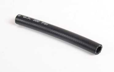


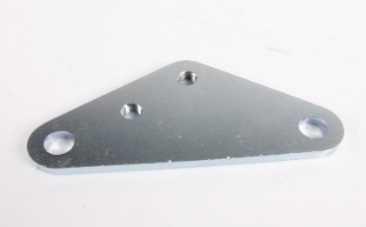

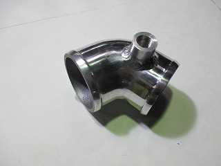
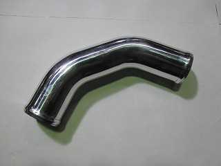


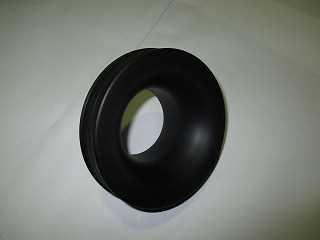
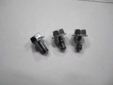
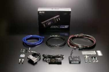
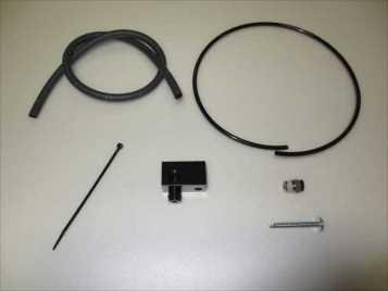
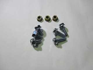
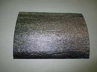
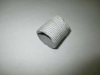
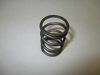
6 Parts picture:


7


8


9
10 1.Preparation / Removal Remember to mark any hose or pipes after detaching (1) Disconnect the negative terminal of battery. (2) Remove the engine under cover. There are 7 plastic clip and 19 bolts. (3) Remove front bumper under cover with 7 plastic clip and 3 bolts. Remove front bumper mounting stay with 3 plastic clip and 3 bolts. (4) Remove front bumper from car. This work need to remove 2 plastic clip and 5 bolts from the front upper part of car body, 7 plastic clip and 2 bolts from lower part of car body, 4 plastic clip and 1 bolt from car side.
 Remove air cleaner box, chamber, cleaner duct, air guide and suction pipe. The mass flow sensor is reused. Please you keep it clean. (8) Remove the exhaust manifold (Header) and exhaust pipe.")
11 (5) Remove the washer tank. (6) Remove bumper reinforcement. Remove the horn from reinforcement. The horn attach to relocation place later. (7) Remove air cleaner box, chamber, cleaner duct, air guide and suction pipe. The mass flow sensor is reused. Please you keep it clean. (8) Remove the exhaust manifold (Header) and exhaust pipe. The air-fuel ratio sensor and O2 sensor as well to be reused. Please you keep these clean.

Remove the radiator core support.")
12 (9) Remove the oil pan from engine. The oil pan as well to be reused after. (10)Remove the oil pressure switch. (11)Remove the radiator core support. Remove 3 bolts from bonnet hood lock then 4 bolts from the upper car body and 2 bolts on the lower car body of the radiator core support.
 : As shown Fig.1 Cut off the support stay (As shown Fig.")

 Please cover the connector of electric fan by the CAG hose. (Fig.")


13 2.Turbo System Installation (1)Modify of the radiator electric fan shroud (LH side) : As shown Fig.1 Cut off the support stay (As shown Fig.2) of the radiator electric fan shroud. Then the wiring of the fan is placed in behind side and fix it with zip tie. (As shown Fig.2) Please cover the connector of electric fan by the CAG hose. (Fig.4) CAG hose : Parts list No.62 In some case you want to use the stainless steel wire. Fig.1 Radiator fan LH side Fig.2 Cut off this part Wiring is placed in behind side. Fig.3 Fig.4 Attach the CAG hose After alteration (2)Modify of the oil pan (2-1)On the oil pan, open a hole of φ20 as shown as below photo. Please refer to Fig.6 and Fig.7 for the hole position. Fig.5 Hole position
Use a nut to temporary fix oil")


14 Fig.6 Fig.7 40mm 35mm 15mm Hole position Hole position (2-2)Use a nut to temporary fix oil drain pipe on the oil pan. Please refer to Fig.8 for the pipe direction. Oil drain pipe : Parts list No.21 Fig.8 Temporary fix (2-3) Temporary fix the oil pan to the engine. Then Temporary fix the exhaust manifold with gasket. Parts list No.2,No.45 It will be removed after the oil drain pipe position is determined. Please reuse genuine bolts for fixing the oil pan and exhaust manifold. Fig.9
 Install the stud bolt of RH side of the turbine flange of the exhaust manifold. (Fig.")
 Put oil drain hose through the heat shield M. Connect the oil outlet pipe to oil drain pipe with oil drain hose.")
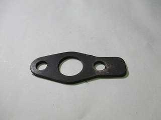
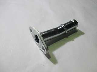
15 (2-4) Attach the supplied oil outlet pipe to the turbo charger assembly using M6 15mm bolts with gasket. Parts list No.22, No.23, No.53 <Tightening torque:10n m(102kgf cm)> Fig.10 Oil outlet pipe M6 15mm Gasket for oil outlet (2-5) Install the stud bolt of RH side of the turbine flange of the exhaust manifold. (Fig.11) Then, turbocharger assembly is temporarily fix to the exhaust manifold using M8x25mm cap screw and M8 nut with flange. Note stud bolt and cap screw positions. Parts list No.1 No.46 No52 Fig.11 Fig.12 Turbo Charger assembly Stud bolt M8 25mm M8 nut (2-6) Put oil drain hose through the heat shield M. Connect the oil outlet pipe to oil drain pipe with oil drain hose. Please make a marking oil drain pipe position. Note drain hose don t touch to exhaust manifold, V belt and crank pulley. (Fig.13) Parts list No.24 No.27 Fig.13 From under view Oil drain hose
 Attach the oil pan with genuine bolt.")
> (3) Attach the supplied turbocharger mounting stay No1 (3-1) Turn the belt tensioner to loosen the V belt. Loosen V belt tensioner by clockwise with a wrench.")
 Remove idler pulley mount bolt from two places. (Fig.15) Prepare 2 M10x50mm bolts, mounting stay No.1, collars of mounting stay.")
16 (2-7) Remove the oil drain hose, turbocharger assembly, exhaust manifold and oil pan (2-8) Remove the nut from the oil drain pipe, then weld the oil drain pipe in the provisionally decided position. Note there is no leakage on the welding part. Please paint the welding part to prevent rust. Oil leaks can cause damage on turbocharger and engine. (2-9) Attach the oil pan with genuine bolt. Make sure the connected surface of oil pan and engine is fully degreased before applying a liquid gasket. Insufficient degreasing leads to oil leakage. <Tightening torque:6.4n m(65kgf cm)> (3) Attach the supplied turbocharger mounting stay No1 (3-1) Turn the belt tensioner to loosen the V belt. Loosen V belt tensioner by clockwise with a wrench. When the tensional is a little loosen, stick in the allen key to fix the V belt. (Fig.14) Fig.14 V belt tensioner Stick in the allen key Rotation direction (3-2) Remove idler pulley mount bolt from two places. (Fig.15) Prepare 2 M10x50mm bolts, mounting stay No.1, collars of mounting stay. (Fig.16) Place the assembly of mounting stay No.1 on to the idler pulley then tighten all hardware. (Fig.17/18) Parts list No.15 No.17 No.54 <Tightening torque:36n m(367kgf cm)> Fig.15 Idler pully Fig.16 Collar of mounting stay Mounting stay No1 M10 50mm


> Fig.19 (4-3) Attach the supplied turbo charger mount stay No.")
17 Fig.17 After attachment Fig.18 (3-3) Finish V-belt back into place by fully retracting the tensioner and correctly routing per the V-belt. Note perform the next process in advance please. (8-1) (8-2) (8-3) (4) Attach the supplied exhaust manifold (4-1) Wrap the exhaust manifold with ceramic fiber turbo wrap and secure it with stainless steel wire. Note wrap the place that close to crank pulley, V belt, radiator electric fan. Parts list No.2 No.48 (4-2) Mount the supplied exhaust manifold to engine using the supplied gasket. (Fig.19) Note use genuine flange nuts. Parts list No.2 No.45 <Tightening torque:30n m(306kgf cm)> Fig.19 (4-3) Attach the supplied turbo charger mount stay No.2 Connect T/C mounting stay No1 to exhaust manifold by T/C mounting stay No2. (Fig.20) Note using supplied bolts. Need to modify fan shroud again when exhaust manifold so close electric fan shroud. Parts list No.16 No.55 Fig.20 M8 12mm Mounting stay No2 M8 20mm


> Fig.22 O2sensor A/F sensor (5-3) Attach M8 stud bolts to the outlet flange of turbocharger assembly.")
18 (5)Attach the turbo charger assembly and turbo down pipe (5-1) Temporarily secure the turbocharger assembly with supplied gasket using M8x25mm cap screw and M8 nut. Note will be tighten after down pipe is mount. Parts list No.43 No.52 Fig.21 M8 25mm (7) ダウンパイプ取付け M8 Nut (5-2) Attachment of A/F sensor and O2 sensor (removed from the genuine exhaust manifold) to the down pipe. Note be caution of the mounting position. A/F ratio sensor (the grey connector): Replace the up side of down pipe O2 sensor (the black connector): replace the low side of down pipe Parts list No.3 <Tightening torque:21n m(214kgf cm)> Fig.22 O2sensor A/F sensor (5-3) Attach M8 stud bolts to the outlet flange of turbocharger assembly. After that, the down pipe with gasket is temporarily fix using M8x25mm cap screw and M8 nut. Each bolts position refer to as well Fig.23 and Fig.24. Parts list No3 No44 No56 Fig.23 under Fig.24 upper M8 Stud bolt M8 25mm M8 Nut
 Adjust the position of the turbocharger assembly, the down pipe, exhaust pipe in best place and then fix all hardware.")
 Regarding O2 sensor and A/F ratio sensor, re-attach connector to the engine side. Fig.")
19 (5-4) Temporarily secure the exhaust pipe and down pipe with gasket for down pipe using M10x25mm bolt and M10 nut. (Fig.25) Parts list No46 No57 Fig.25 Down pipe Exhaust pipe M10 25mm M10 Nut Gasket (5-5) Adjust the position of the turbocharger assembly, the down pipe, exhaust pipe in best place and then fix all hardware. Exhaust manifold to turbo charger <Tightening torque:25n m(255kgf cm)> Turbocharger to down pipe <Tightening torque:25n m(255kgf cm)> Down pipe to exhaust pipe <Tightening torque :35N m(357kgf cm)> (5-6) Regarding O2 sensor and A/F ratio sensor, re-attach connector to the engine side. Fig.26 Black:O2sensor Grey:A/Fsensor (6)Attach oil drain hose Connect the oil drain hose (has been wrapped with heat shield) with oil outlet pipe and oil drain pipe by using hose clamp No.2. Note drain hose don t touch to exhaust manifold, V belt and crank pulley. Please use supplied zip tie if necessary. Parts list No21 No27 NO38 Fig.27


20 (7)Attach the supplied turbo charger bypass hose (Actuator) For customer, who purchased FULLKIT, please install the boost controller kit (SBC type S). Please refer to installation manual of SBC. And It is easy to take manifold pressure with Boost Sensor Adpter. φ4 silicon tube, φ4-φ6 union fitting and φ6 silicon tube are used to connect the turbocharger with the actuator and turbo compressor housing. (Fig.28) Cut the silicon tube to fit the required length. Parts list No34 No35 No36 Fig.28 φ4silicon tube φ4-φ6 union fitting φ6silicon tube (8) Attach the supplied oil line for turbo charger Note use liquid gasket or sealing tape on the threaded portion, which is connected to the straight union and 3-ways union. Mixing of oil line into the gasket dust will cause clogging that will damage the turbocharger. So be sure that the liquid gasket does not protrude into the oil line when applying. (8-1) Mount the straight union with the genuine oil pressure switch on the mounting position. (Fig.29) Parts list No28 <Tightening torque:18n m(184kgf cm)> Fig.29 (8-2) Attach the 3-way union to the straight union. 3-way union must be attached while direction the connection port in vertically. (Fig.30) Parts list No29

 Re-attach connector to the genuine oil pressure switch.")

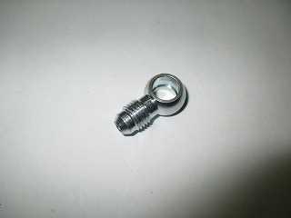
21 Fig.30 (8-3) Attach the genuine oil pressure switch on the upper part of the 3-way union and 90 degree angle union on the lower part of 3-way union. (Fig.31) Parts list No30 Fig.31 (8-4) Re-attach connector to the genuine oil pressure switch. (8-5) Attach the banjo and banjo bolt using 2 copper washers to the turbocharger. The banjo connection port must be facing the front side of the vehicle. (Fig.32) Parts list No31 No32 No33 <Tightening torque:15n m(153kgf cm)> Fig.32 Front of the vehicle
 Parts list No25 No26 Fig.")
 Hole size is about φ5mm. Fig.")

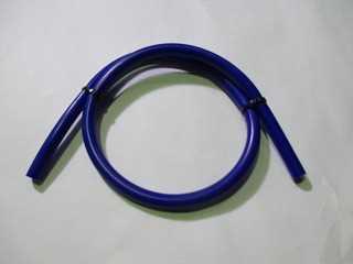
22 (8-6) Cover the oil feed hose with heat shield S, and then connect the oil feed hose to the banjo and the 90 degree angle union. (Fig.33) Parts list No25 No26 Fig.33 Banjo 90 degree union Oil feed hose (8-7) Drill a hole on the shroud of the electric fan, secure the oil feed hose with zip tie. (Fig.34) Hole size is about φ5mm. Fig.34 Use the zip tie (9)Attach the supplied heat shield of exhaust housing Attach the heat shield of exhaust housing on the front pipe using M6x12mm cap screw. (Fig.35) Parts list No4 No58 <Tightening torque:10n m(102kgf cm)> Fig.35 M6 12mm
 Install the 90 degree elbow fitting to the suction pipe, and using 2 piece of silicon hose No.1 and hose clamp No.")
 Note use liquid gasket or sealing tape on the threaded portion, which is connected to the suction pipe. Parts list No5 No9 No40 Fig.")

23 (10)Attach the supplied air cleaner (10-1) Attach the air cleaner to air cleaner attachment using hose clamp. (Fig.36) Parts list No50 No51 Fig.36 Air cleaner attachment (10-2) Install the 90 degree elbow fitting to the suction pipe, and using 2 piece of silicon hose No.1 and hose clamp No.4 to mount the suction pipe from the air cleaner to the turbo charger. (Fig.37) Note use liquid gasket or sealing tape on the threaded portion, which is connected to the suction pipe. Parts list No5 No9 No40 Fig.37 Hose clamp No4 Silicon hoseno1 90 degree elbow fitting (10-3) Connect the blow-by hose and blow-by hose joint pipe by using 2 hose clamp No.1 from 90 degree elbow fitting to genuine ventilation hose. Move the genuine ventilation hose and relocated it between oil filter and alternator cover. (Fig.38) Parts list No8 No13 No14 No37 Fig.38 Relocation the ventilation hose Joint pipe for blow by hose Hose clamp No1 Blow by hose
 Parts list No.66 Fig.39 Fig.")

 Prepare the previously removed front bumper reinforcement and put it against the intercooler assembly.")
 Be caution to not to trim off the bolt hole to be used for the intercooler stay on the RH side.")
24 (10-4) Remove the belt alternator cover and set belt cover. secure the blow-by hose to the belt cover using zip tie. (Fig.39 / Fig.40) Parts list No.66 Fig.39 Fig.40 (10-5) Applied to prevent coming off fuel vapor field hose No.1 and No.2 under the intake manifold. Using the supplied zip tie. Total 4 places. To prevent coming off hose (11)Inter cooler installation(reinforcement and radiator core support modify) (11-1) Prepare the previously removed front bumper reinforcement and put it against the intercooler assembly. Then mark the area to trim off for intercooler. (Fig.41) Be caution to not to trim off the bolt hole to be used for the intercooler stay on the RH side. Please trim dimensions refer to Fig.42 and Fig.43. After mounting the body on LH side, drill a hole for mounting the intercooler. Note anti-rust painted the cut portion. Fig.41 Trim off area


25 Fig.42 RH Fig.43 LH 57mm 29mm Fig.44 RH from bottom view Fig.45 LH from bottom view Use this screw hole Drill a hole later(φ7) (11-2) Install the cut front bumper reinforcement. (11-3) Relocate the genuine horn. Refer to below picture. Parts list No65 Remove: Don t use. Remove Genuine Horn Using the supplied M6 16 and M6 nut. Slide to make a clearance


 for fixing. (Fig.")
 The horn relocated to another location.")
 Parts list No18 No19 No20 No60 Fig.")
26 (11-4) Secure the intercooler by using the intercooler mounting stay No.1, No.2 and No.3. Note mounting stay, left and right position. Use supplied bolt and nut. M6x20mm hex flange bolt, M6 nut and M8x12mm flange bolt. Temporarily secure the intercooler assembly by using the intercooler mounting stay No.1 and No.3. Carefully position the intercooler so as to be centered, and parallel with the A/C condenser, then the intercooler mounting stay No.2 to get a position to drill a hole (φ7) for fixing. (Fig.47) Regarding mounting stay No1, instead of genuine screw, use the supplied M6 20mm flange bolt and M6 nut. (Fig.46) The horn relocated to another location. Regarding mounting stay No3, secure the body by using M6x20mm flange bolt and M6 nut. (Fig.48) Parts list No18 No19 No20 No60 Fig.46 M6 20mm and M6 Nut Remove the horn stay Mounting stay No1 (RH) Reinforcement RH M8 12mm flange bolt Fig.47 M6 20mm and M6 nut Carefully drill a hole of φ7 Mounting stay No2 (LH) M8 12mm Reinforcement LH view from bottom Fig.48 M8 12mm flange bolt Secure mounting stay No.3 by using M6 nut in inside Intercooler mounting stay No3 (LH) M6 20mm flange bolt


27 (11-5) Temporarily locate the supplied intake pipe No.1 on to the turbocharger assembly. Using the supplied 2 silicon hose No.2 and 4 hose clamp No.3. Parts list No6 No10 No39 Fig.49 Turbo charger assembly Hose clamp No3 Silicon hose No2 Intake pipe No1 (11-6) locate the supplied intake pipe No.2 to the throttle body. Using the supplied silicon hose No.3, silicon hose No.4, 2 hose clamp No.4, 1 hose clamp No.5 and 1 hose clamp No.6. Note intake pipe No.2 will be hot so close to the exhaust manifold. Pasted heat shield cloth on the side close exhaust manifold. Parts list No7 No11 No12 No40 No41 No42 No61 Fig.50 Throttle body side Fig.51 Inter cooler side Silicon hoseno4 Silicon hose No3 Hose clampno6 Intake pipe No2 Hose clampno5 Hose clamp No4 (11-7) Attach intake pipe No1 and No2 to the intercooler assembly with the silicon hose provided. (Fig.52) Parts list No.49 Fig.52

 Adjust all pipe position and attach the supplied hose clamp each place.")
> (11-10) Relocate genuine MAF sensor to")
> Fig.")
28 (11-8) Temporarily mount the radiator core support which removed in a previous step. This core support need to be modified to accommodate each intake pipe. Trim off all shaded areas for intake pipe. (Fig.53/Fig.54) Fig.53 Fig.54 Trim off Trim off (11-9) Adjust all pipe position and attach the supplied hose clamp each place. Then tighten every clamp and attach radiator core support and bonnet hood lock. <Tightening torque of core support and hood lock:18n m(184kgf cm)> (11-10) Relocate genuine MAF sensor to intake pipe No.2. Using the supplied M4x8 pan head screw. Note re-attach connector. Parts list No59 <Tightening torque:4.0n m(41kgf cm)> Fig.55 M4 8 pan head screw (12)Replace the MAP sensor Replace the Map sensor with the supplied unit using genuine bolt. Note re-attach connector. Parts list No47 <Tightening torque:4.0n m(41kgf cm)> Fig.56 MAP sensor
29 (13) Attach washer tank, front bumper, front under cover, bumper under cover. Attach all in reverse order of removing. (14) Wait until the liquid gasket of oil pan complete hardens before injecting engine oil. (15) In case of STARTUP KIT and FULL KIT, please install the rewrite ECU(B-EMU). (16) Re-connect the negative terminal of battery. 3.Final check Warning: Do not attempt to operate the vehicle until all components are installed and all operations are completed including the final check. If your vehicle has gone over 30,000km since its last spark plug change, you should change the new one. Re-check all fluid levels, making sure that your tank need be filled with 98 octane or more higher fuel. Do cranking a few time before start up. Start the engine and allow to idle a few minutes, then shut off. Re-check to be sure that no hoses, wires, any other thing are exhaust manifold or moving parts. Look also for any signs of fluid and air leakage during idling. Adjust the tension of the actuator rod to not exceed 0.5hkp during peak boost. Customers, who purchase FULL KIT, please adjust the boost controller (SBCtypes) to not exceed 0,5hkpa. Replace the spark plug base on the engine condition. After all setting is done be sure to tighten every band and screw. In some cases, must remove the hood prop rod completely from vehicle or need to bend the hood prop rod to be fit.
30 Set pressure adjustment for Actuator: 1Refer to Fig.A2, need to prepare pressure supply device and boost gauge. Change the initial pressure to adjust the turnbuckle of actuator rod. Note be sure to adjust it to not exceed recommend boost. Recommend Boost:0.5 hkpa and fewer Standard length : Refer to Fig.A2 Set pressure 0.5hkPa STD length:150.0mm This value is a reference. In some case, there are other value different from this. Standard set length, measure it remove actuator from the turbo charger. 2After adjustment, secured turnbuckle and then attached it to turbo charger. Fig.A1 Boost gauge Fig.A2 STD length actuator Air pressure Adjustment of the boost pressure is gradually increased from lower value upon confirmation each time. Each vehicle with different element and parts will cause slight difference in boost pressure. Also, install of other components than this turbo system may lead different adjustments needed. Always listen carefully for engine detonation. Discontinue heavy throttle usage if detonation is heard. The higher gear used when driving, will lead to higher boost pressure. Be sure to adjust it to not exceed the maximum boost. (0.5hkPa) If the numbers still not exceed 0.5hkpa even after adjustment, please replace to hi type spring of the actuator. Parts list No.63 Set pressure 0.7hkPa STD length:156.5mm 4.Maintenance For more comfortable drive, please do a daily inspection before driving. Engine oil SAE viscosity 10W-30, 10W-40, 5W-40 (100% Full synthetic Polyol ester) is recommended. Change engine oil and oil filter regularly. (Every 3000km is recommended) Tighten every screw regularly. Be sure to use high-octane gasoline. Over 98.

31 5.Data sheet of power graph Reference of power check data Settings of boost pressure is around 0.5hkPa is the characteristic of B-EMU installment. Use chassis dynamometer from Bosch. Boost pressure 0.5hkpa with boost controller (SBC types) ECU TUNE : BLITZ ORIGINAL DATA B-EMU (JAPAN SPEC) The manual number First edition created by February 10, 2015
32
Scion FR-S ZN6. GTX2867R Gen2 (Internal Wastegate) Installation Instructions GPP P/N #
 Installation Instructions GPP P/N #") TURBO KIT Scion FR-S ZN6 Subaru BRZ ZC6 GTX2867R Gen2 (Internal Wastegate) Installation Instructions GPP P/N # 11518000 Vehicle Type Chassis Code Engine Code Transmission Model Year Scion FR-S DBA-ZN6
TURBO KIT Scion FR-S ZN6 Subaru BRZ ZC6 GTX2867R Gen2 (Internal Wastegate) Installation Instructions GPP P/N # 11518000 Vehicle Type Chassis Code Engine Code Transmission Model Year Scion FR-S DBA-ZN6
R35 GT-R GT1000 FULL TURBINE KIT INSTALLATION MANUAL
 R35 GT-R GT1000 FULL TURBINE KIT INSTALLATION MANUAL Installation must be done by a professional. Read this manual prior to the installation. Always have access to this manual as well as a factory service
05-08 GT. Hellion Power Systems Mustang Kit Instructions
 Hellion Power Systems 05-08 Mustang Kit Instructions 1. Disconnect Battery 2. Drain Radiator, keep fluid for re-installation. 3. Remove air box and inlethoses. 6. Next, underneath, punch oil pan for turbo
Procharger Stage II Intercooled Supercharger System (11-14 GT)
") Procharger Stage II Intercooled Supercharger System (11-14 GT) Installation Time: Approximately one day. Installed on 2012 Mustang GT 5.0/Manual Required Tools 3/8 Socket Set (Standard and Metric) 1/2
Procharger Stage II Intercooled Supercharger System (11-14 GT) Installation Time: Approximately one day. Installed on 2012 Mustang GT 5.0/Manual Required Tools 3/8 Socket Set (Standard and Metric) 1/2
Installation Manual. Model Chassis Code Engine Code Year
 INTERCOOLER KIT NISSAN GT-R R35 (VR38 38DETT) SPEC-R HG TYPE29 Full KIT Installation Manual Please read the Installation Manual before installing. Keep this manual for future reference. Model Chassis Code
4. Remove (4) 10mm and (1) 7mm bolt that holds fascia at front corners, on each side
 10mm and (1) 7mm bolt that holds fascia at front corners, on each side") 2010 Camaro LS3 1. Disconnect battery ground 2. Remove front wheels 3. Remove (5) push pins and (5) #20 torx screws on inner front wheel well liners and remove liners on each side 4. Remove (4) 10mm and
2010 Camaro LS3 1. Disconnect battery ground 2. Remove front wheels 3. Remove (5) push pins and (5) #20 torx screws on inner front wheel well liners and remove liners on each side 4. Remove (4) 10mm and
Installation Manual. Model Chassis Code Engine Code Year
 INTERCOOLER KIT NISSAN GT-R R35 (VR38 38DETT) SPEC-R HG TYPE29 Full KIT Installation Manual Please read the Installation Manual before installing. Keep this manual for future reference. Model Chassis Code
Huron Speed Products Twin Turbo Install Gen 2 CTS-V (09-15)
") Huron Speed Products Twin Turbo Install Gen 2 CTS-V (09-15) The following install guide is simply that, a guide to help you with installation. It is by no means the exact method to perform installation,
Huron Speed Products Twin Turbo Install Gen 2 CTS-V (09-15) The following install guide is simply that, a guide to help you with installation. It is by no means the exact method to perform installation,
LChevrolet Camaro Supercharger Kit
 PART #92000A Important Notes: 2010-2013 6.2LChevrolet Camaro Supercharger Kit The use of fuel additives (ie. octane boosters) is not recommended. There is a possibility that these chemicals can damage
Always wear safety glasses when working on your vehicle.
 90-93 MAZDA MIATA SUPERCHARGER KIT The KraftWerks 90-93 Mazda Miata Supercharger Kit was designed for easy installation. Competent mechanics with the appropriate tools will find the process to be relatively
Installation Instructions for: TOYOTA 4.5L SUPERCHARGER SYSTEM
 Installation Instructions for: TOYOTA 4.5L SUPERCHARGER SYSTEM 1995-1997 Land Cruiser * PREMIUM FUEL REQUIRED * Magnuson Products LLC 1990 Knoll Drive, Bldg A, Ventura, CA 93003 (805) 642-8833 phone *
Huron Speed Products Twin Turbo Install Gen 2 CTS-V (09-15)
") Huron Speed Products Twin Turbo Install Gen 2 CTS-V (09-15) 1 2 Remove two bolts in trunk cover with 8mm socket. Pull up on cover to remove. Unscrew net tie down on side cover where battery is located
Huron Speed Products Twin Turbo Install Gen 2 CTS-V (09-15) 1 2 Remove two bolts in trunk cover with 8mm socket. Pull up on cover to remove. Unscrew net tie down on side cover where battery is located
CHALLENGER TWIN TURBO SYSTEM INSTALLATION INSTRUCTIONS
 CHALLENGER TWIN TURBO SYSTEM INSTALLATION INSTRUCTIONS 1 Verify contents of kits with supplied packing list 1) Unhook the battery. 2) Remove wheel wells & front fascia of vehicle. 3) Remove the catalytic
Instant Chat off the main page of Or simply call our tech team at
 FRONT MOUNT INTERCOOLER 2008-13 STI 2014-04- 08 Thank you for purchasing this PERRIN product for your car! Installation of this product should only be performed by persons experienced with installation
GT-R Alpha 10/12 Turbo Kit
 GT-R Alpha 10/12 Turbo Kit Instructions V6 The goal of AMS is to provide the highest quality, best performing products available. By utilizing research and development, and rigorous testing programs AMS
2017+ L5P Duramax 3 ½ Down Pipe & EGR Fix Kit
 2017+ L5P Duramax 3 ½ Down Pipe & EGR Fix Kit Covers installation of PN s: WCF100630, WCF100829 Note: This Kit is for off road competition use only! Off Road Competition Use Tuning & Exhaust System is
BD 6.7L Super B Special Turbo Kit For L Dodge -- I n s t a l l a t i o n I n s t r u c t i o n s -- PN#
 28 January 2014 1045140 6.7L Super B Special Turbo Installation (I-00266) 1 BD 6.7L Super B Special Turbo Kit For 2007.5-2012 6.7L Dodge -- I n s t a l l a t i o n I n s t r u c t i o n s -- PN# 1045140
3 October 2016 PN# V Dodge Twin Turbo Kit (I-00274) ½ D o d g e 2 4 v I S B
 ½ D o d g e 2 4 v I S B") 3 October 2016 PN#1045320 24V Dodge Twin Turbo Kit (I-00274) 1 DOWNLOAD ENHANCED INSTALL MANUALS AT dieselperformance.com BD Twin Turbo Kit 1998½- 2 0 0 2 D o d g e 2 4 v I S B Part# 1045320 PLEASE READ
3 October 2016 PN#1045320 24V Dodge Twin Turbo Kit (I-00274) 1 DOWNLOAD ENHANCED INSTALL MANUALS AT dieselperformance.com BD Twin Turbo Kit 1998½- 2 0 0 2 D o d g e 2 4 v I S B Part# 1045320 PLEASE READ
03-04 Mach 1. Hellion Power Systems Mach 1 Kit Instructions
 Hellion Power Systems 03-04 Mach 1 Kit Instructions Part 1 Hellion recommends that the front suspension system be installed either by trained professionals or by 5.Remove rack bolts K-Member Installation
2006 Honda Civic SI Supercharger Kit Installation Instruction Kit #
 2006 Honda Civic SI Supercharger Kit Installation Instruction Kit #350-091 3239 MONIER CIRCLE, STE.5 RANCHO CORDOVA, CA 95742 916.635.4550 FAX 916.635.4632 www.ct-engineering.com INS-157 VERSION: 3.25.2009
Disconnect the APP sensor harness connector. See Fig. 4. Remove the accelerator pedal mounting nuts. Remove the APP assembly.
 ENGINE CONTROLS - REMOVAL, OVERHAUL & INSTALLATION - 6.6L DIESEL... Page 1 of 41 FUEL SYSTEMS ACCELERATOR PEDAL POSITION SENSOR Removal & Installation Disconnect the APP sensor harness connector. See Fig.
INSTALL MANUAL D o d g e 1 2 v 6 B T A PLEASE READ ALL INSTRUCTIONS BEFORE INSTALLATION.
 PN#1045310 12V Dodge Twin Turbo Kit (I-00273) 1 INSTALL MANUAL BD Twin Turbo Kit 1994-1 9 9 8 D o d g e 1 2 v 6 B T A Part# 1045310 PLEASE READ ALL INSTRUCTIONS BEFORE INSTALLATION. * Picture as shown
TURBO KIT INSTRUCTIONS
 Revision 12/20/10 TURBO KIT INSTRUCTIONS This turbo kit consists of the necessary parts to upgrade or add a turbo to your 22R/RE/RET. This kit may require some fabrication to address your particular application
1996 Aerostar/Ranger/Explorer
 Page 1 of 11 Section 03-01B: Engine, 3.0L V-6 IN-VEHICLE SERVICE 1996 Aerostar and Ranger Vehicles Workshop Manual Water Pump SPECIAL SERVICE TOOL(S) REQUIRED Description Tool Number Fan Clutch Holding
WARNING: ALWAYS relieve fuel pressure before disconnecting any fuel related component. DO NOT allow fuel to contact engine or electrical components.
 4.0L V8 - VINS [K,U] Selected Block 1990 Lexus LS 400 For Lextreme Powertrain 2020 S. Hacienda Blvd. # D Hacienda Heights California 91745 Copyright 1998 Mitchell Repair Information Company, LLC Friday,
INTAKE AND EXHAUST GROUP CONTENTS GENERAL INFORMATION SERVICE SPECIFICATION AIR CLEANER
 15-1 GROUP 15 INTAKE AND EXHAUST CONTENTS GENERAL INFORMATION 15-2 SERVICE SPECIFICATION 15-2 DIAGNOSIS 15-2 INTRODUCTION 15-2 TROUBLESHOOTING STRATEGY 15-2 SYMPTOM CHART 15-2 SYMPTOM PROCEDURES 15-3 SPECIAL
PowerMax Diesel Upgrade For Cummins Engines
 PowerMax Diesel Upgrade For Cummins Engines 00.5-007.5 Dodge Ram With Cummins 5.9L Item 3 4 5 6 7 8 9 0 3 4 5 6 7 8 Parts List Description Turbocharger Ancillary kit 773069- (includes) Installation Instructions
2015+ SUBARU STI FRONT-MOUNT INTERCOOLER PARTS LIST AND INSTALLATION GUIDE INSTALL DIFFICULTY DISCLAIMER CAUTION INSTALL PROCEDURE TOOLS NEEDED
 PARTS LIST AND PARTS INCLUDED 1PC ALUMINUM INTAKE PIPE 1PC BAR-AND-PLATE INTERCOOLER 1PC STEEL CRASH BAR W/ MOUNTING HARDWARE 2PC HOT-SIDE INTERCOOLER PIPES 2PC COLD-SIDE INTERCOOLER PIPES 1PC BPV FLANGE
99-04 GT. Hellion Power Systems Mustang GT Kit Instructions
 Hellion Power Systems 99-04 Mustang GT Kit Instructions Part 1 Hellion recommends that the front suspension system be installed either by trained professionals or by 5.Remove rack bolts K-Member Installation
BD 6.7L Super B Special Turbo Kit For L Dodge -- I n s t a l l a t i o n I n s t r u c t i o n s -- PN#
 26 September 2012 1045140 6.7L Super B Special Turbo Installation 1 BD 6.7L Super B Special Turbo Kit For 2007.5-2012 6.7L Dodge -- I n s t a l l a t i o n I n s t r u c t i o n s -- PN# 1045140 PLEASE
IAG Street Series Air / Oil Separator (AOS) For WRX
 For WRX") P IAG Street Series Air / Oil Separator (AOS) For 2015-16 WRX Part# IAG-ENG-7152 Tools Required: Ratchet, torque wrench, extensions, needle nose pliers, hose cutter, snips/scissors, flat head screw driver,
P IAG Street Series Air / Oil Separator (AOS) For 2015-16 WRX Part# IAG-ENG-7152 Tools Required: Ratchet, torque wrench, extensions, needle nose pliers, hose cutter, snips/scissors, flat head screw driver,
Phone Fax
 Directions for Installation of ECS Paxton Supercharger Kit Disconnect battery Remove stock serpentine belt Remove stock belt tensioner, save the 2 bolts for later use on supercharger bracket Remove alternator
Instant Chat off the main page of Or simply call our tech team at
 FRONT MOUNT INTERCOOLER 2015+ WRX 2017-07-07 Thank you for purchasing this PERRIN product for your car! Installation of this product should only be performed by persons experienced with installation of
Step 6: Remove and save the MAP sensor for later use. Step 7: Remove the passenger side intercooler pipe and the EGR intake manifold.
 LBZ Twin kit Install Step 1: Disconnect both batteries. Step 2: Drain coolant and oil also remove passenger side inner fender. Step 3: Remove intake box and piping. (Remove and save the MAF sensor in the
V1 Truck Manifold Turbo Kit for F-body
 V1 Truck Manifold Turbo Kit for 98-02 F-body Prep: -Remove all A/C Components, Alternator and brackets, tensioner, front bumper, front bumper foam, and front bumper support. Remove radiator and cooling
IAG Air / Oil Separator (AOS) For STi
 For STi") IAG Air / Oil Separator (AOS) For 2008-14 STi Part# IAG-ENG-7000 Tools Required: Ratchet, torque wrench, extensions, needle nose pliers, hose cutter, snips/scissors Sockets: 10mm, 12mm 13mm Wrenches: 10mm,
IAG Air / Oil Separator (AOS) For 2008-14 STi Part# IAG-ENG-7000 Tools Required: Ratchet, torque wrench, extensions, needle nose pliers, hose cutter, snips/scissors Sockets: 10mm, 12mm 13mm Wrenches: 10mm,
4 December 2017 PN# , , Dodge 6.7L Rumble B SXE (I-00400) 1. BD Rumble B SXE. D o d g e 6. 7 L H P C R Installation Instructions
 1. BD Rumble B SXE. D o d g e 6. 7 L H P C R Installation Instructions") 4 December 2017 PN#1045705, 1045706, 1045708 Dodge 6.7L Rumble B SXE (I-00400) 1 DOWNLOAD ENHANCED INSTALL MANUALS AT dieselperformance.com BD Rumble B SXE D o d g e 6. 7 L H P C R Installation Instructions
4 December 2017 PN#1045705, 1045706, 1045708 Dodge 6.7L Rumble B SXE (I-00400) 1 DOWNLOAD ENHANCED INSTALL MANUALS AT dieselperformance.com BD Rumble B SXE D o d g e 6. 7 L H P C R Installation Instructions
LML 3 Y-Bridge Kit or High Flow Intake Bundle Package
 2011-2016 LML 3 Y-Bridge Kit or High Flow Intake Bundle Package Covers installation of PN s: WCF100607, WCF100691, WCF100716, & WCF100353 Note: This Kit is for off road competition use only! Overview-
TURBOCHARGER ON VEHICLE INSPECTION TC 7
 TC7 ONVEHICLE INSPECTION 1. INSPECT INTAKE AIR SYSTEM Check for leakage or clogging between the air cleaner and turbocharger inlet and between the turbocharger outlet and cylinder head. Clogged air cleaner...
IAG Competition Series Air / Oil Separator (AOS) For WRX
 For WRX") P IAG Competition Series Air / Oil Separator (AOS) For 2015-16 WRX Part# IAG-ENG-7252 Tools Required: Ratchet, torque wrench, extensions, needle nose pliers, hose cutter, snips/scissors, flat head screw
P IAG Competition Series Air / Oil Separator (AOS) For 2015-16 WRX Part# IAG-ENG-7252 Tools Required: Ratchet, torque wrench, extensions, needle nose pliers, hose cutter, snips/scissors, flat head screw
Installation Instructions
 2011-2013 LML DURAMAX COMPOUND-ADD 2011-2015 LML A Duramax TURBO KIT Add INSTALL A Turbo INSTRUCTIONS Compound Kit Installation Instructions 1-800-955-0476 - www.industrialinjection.com - info@industrialinjection.com
INSTALLATION INSTRUCTIONS AOS-R (Air Oil Separator-Return) Turbo Subaru and STi Document# Support:
 Turbo Subaru and STi Document# Support:") INSTALLATION INSTRUCTIONS AOS-R (Air Oil Separator-Return) 02-14 Turbo Subaru and 2015+ STi Document# 19-0102 Support: info@radiumauto.com These instructions are based on a vehicle with an OEM turbocharger
INSTALLATION INSTRUCTIONS AOS-R (Air Oil Separator-Return) 02-14 Turbo Subaru and 2015+ STi Document# 19-0102 Support: info@radiumauto.com These instructions are based on a vehicle with an OEM turbocharger
Installation Instructions for: TOYOTA 3.4L SUPERCHARGER SYSTEM
 Installation Instructions for: TOYOTA 3.4L SUPERCHARGER SYSTEM 1996-2002 4Runner 1997-1998 T100 1997-2004 Tacoma 2000-2003 Tundra * PREMIUM FUEL REQUIRED * Magnuson Products LLC 1990 Knoll Drive, Bldg
Ford 6.0L. Part #: Part #: BD GASKET PART# will be needed for this installation.
 1 BD EGR COOLER 2003-2007 Ford 6.0L Part #: 1090201 Part #: 1090202 PLEASE READ ALL INSTRUCTIONS BEFORE INSTALLATION BD GASKET PART# 1090002 will be needed for this installation. 2 K I T C O N T E N T
PARTIAL ENGINE ASSY (2TR FE)
") COMPONENTS 147 1421Z01 Clip Hood Subassy x9 Radiator Support to Frame Seal LH 30 (306, 22) 30 (306, 22) Fan and Generator V Belt 5.0 (51, 44 in. lbf) Fan Shroud Fan Pulley Fan w/ Fluid Coupling PRE RUNNER
COMPONENTS 147 1421Z01 Clip Hood Subassy x9 Radiator Support to Frame Seal LH 30 (306, 22) 30 (306, 22) Fan and Generator V Belt 5.0 (51, 44 in. lbf) Fan Shroud Fan Pulley Fan w/ Fluid Coupling PRE RUNNER
96-04 tt. Hellion Power Systems Mustang Twin Turbo Kit Instructions
 96-04 tt Hellion Power Systems 1996-2004 Mustang Twin Turbo Kit Instructions 1. Disconnect battery and elevate front end of car on either Jack stands or a lift if available 2.Lock steering wheel and remove
REMOVAL & INSTALLATION
 REMOVAL & INSTALLATION NOTE: For reassembly reference, label all electrical connectors, vacuum hoses and fuel lines before removal. Also place mating marks on engine hood and other major assemblies before
INSTALLATION INSTRUCTIONS AOS-R (Air Oil Separator-Return) Turbo Subaru and STi
 Turbo Subaru and STi") INSTALLATION INSTRUCTIONS AOS-R (Air Oil Separator-Return) 02-14 Turbo Subaru and 2015+ STi These instructions are based on a vehicle with an OEM turbocharger and top-mount intercooler. If a front-mount
INSTALLATION INSTRUCTIONS AOS-R (Air Oil Separator-Return) 02-14 Turbo Subaru and 2015+ STi These instructions are based on a vehicle with an OEM turbocharger and top-mount intercooler. If a front-mount
TURBOCHARGER Toyota Celica DESCRIPTION OPERATION TURBOCHARGING SYSTEMS All Models
 TURBOCHARGER 1988 Toyota Celica 1988 TURBOCHARGING SYSTEMS All Models DESCRIPTION Most models use a water-cooled turbocharger, mounted directly to the exhaust manifold with a wastegate assembly attached
Section 10 Chapter 17
 Section 10 Chapter 17 24 Valve, 8.3 Liter Engine Air Intake System Note: All coding used in the 8.3 Liter and 9 Liter engine manuals are Cummins engine codes. These engine codes have no meaning to New
Instant Chat off the main page of Or simply call our tech team at
 Subaru WRX/STI Air Oil Separator for Front Mounted Intercooler Setups 2013-02- 22 Thank you for purchasing this PERRIN product for your car! Installation of this product should only be performed by persons
Always use fuel with a minimum octane rating of 93 (R+M)/2. (Equivalent to 98 RON).
/2. (Equivalent to 98 RON).") Before Commencing Installation Verify that you have all necessary tools as listed. Clean all air ducting prior to commencing installation. The sequence of installation of each part is very important. It
Before Commencing Installation Verify that you have all necessary tools as listed. Clean all air ducting prior to commencing installation. The sequence of installation of each part is very important. It
INSTALLATION INSTRUCTIONS AOS-R (Air Oil Separator-Return) Turbo Subaru and STi Document# Support:
 Turbo Subaru and STi Document# Support:") INSTALLATION INSTRUCTIONS AOS-R (Air Oil Separator-Return) 02-14 Turbo Subaru and 2015+ STi Document# 19-0102 Support: info@radiumauto.com These instructions are based on a vehicle with an OEM turbocharger
INSTALLATION INSTRUCTIONS AOS-R (Air Oil Separator-Return) 02-14 Turbo Subaru and 2015+ STi Document# 19-0102 Support: info@radiumauto.com These instructions are based on a vehicle with an OEM turbocharger
Installation Manual v1.0: Twin CP3 Fuel Injection Kit Dodge 5.9L
 Installation Manual v1.0: Twin CP3 Fuel Injection Kit 2004.5-2007 Dodge 5.9L Figure 1 - Full Kit Photo 25 Figure 2 - Hardware Kit Please read all instructions before installation. This kit is not emissions
Installation manual BMW E TS1/TS2
 Installation manual BMW E46 330 TS1/TS2 Technical support Europe: +4741558555 Technical support USA: (858)314-2954 Email support: support@esstuning Installation manual BMW E46 330 TS1/TS2 Remove and send
INSTALLATION INSTRUCTIONS AIR/OIL SEPARATOR KIT
 INSTALLATION INSTRUCTIONS AIR/OIL SEPARATOR KIT 2015+ SUBARU WRX (LHD ONLY) Document: 19-0136 Support: info@radiumauto.com This document covers the installation of the Radium brake master cylinder brace
Included parts: 1 - BorgWarner SX-E Turbocharger 1 - SX-E 90-Degree Compressor Outlet Elbow 1 - HSM Cast Exhaust Manifold 1 - HSM Downpipe
 TROUBLESHOOTING: Please read and understand all installation instructions before proceeding with the installation. If you have questions during the installation of this product, please email H&S Motorsports
ZX-14 Stage I Turbo Kit
 62910 Peerless Ct. Bend, OR 97701 Phone 541.385.0706 Fax 541.382.9406 ZX-14 Stage I Turbo Kit WARNING: This turbo kit is for OFF-ROAD RACING use ONLY. Advisement: These instructions are written to be comprehensive
Burien Toyota 5S-FE Turbocharger
 Burien Toyota 5S-FE Turbocharger Burien Toyota Seattle, WA 98148 Revised May 9, 2002 Burien Toyota 5SFE Turbo Installation Instructions Disclaimer: This project and related modifications are the responsibility
Included parts: 1 - BorgWarner SX-E Turbocharger 1 - SX-E 90-Degree Compressor Outlet Elbow 1 - HSM Cast Exhaust Manifold 1 - HSM Downpipe
 TROUBLESHOOTING: Please read and understand all installation instructions before proceeding with the installation. If you have questions during the installation of this product, please email H&S Motorsports
TURBOCHARGER SYSTEM TURBOCHARGER TC 1
 TURBOCHARGER SYSTEM TURBOCHARGER TC1 TC2 TURBOCHARGER SYSTEM Description DESCRIPTION Systems which increase the amount of air sent to the engine are either turbocharger type (using exhaust gas to turn
Installation Manual v1.0: Aurora Plus Turbo Kit ( ) 5.9L Dodge. Please read all instructions before installation.
 5.9L Dodge. Please read all instructions before installation.") Installation Manual v1.0: Aurora Plus - 4000 Turbo Kit (2003-2007) 5.9L Dodge Please read all instructions before installation. Figure 1: Aurora Plus - 4000 Kit Contents 1 Figure 2: Aurora Plus Hardware
Installation Manual v1.0: Aurora Plus - 4000 Turbo Kit (2003-2007) 5.9L Dodge Please read all instructions before installation. Figure 1: Aurora Plus - 4000 Kit Contents 1 Figure 2: Aurora Plus Hardware
INSTALLATION INSTRUCTIONS DUAL OIL CATCH CAN KIT
 INSTALLATION INSTRUCTIONS DUAL OIL CATCH CAN KIT SUBARU WRX FA20F ENGINE Document: 19-0135 Support: info@radiumauto.com This dual catch can kit installs in the right-hand side of the engine bay and intercepts
BD SUPER B SINGLE TURBO KIT Dodge 5.9L Cummins v ISBe (Non 600 motors)
") 1 DOWNLOAD ENHANCED INSTALL MANUALS AT dieselperformance.com BD SUPER B SINGLE TURBO KIT Dodge 5.9L Cummins 2003-2004 24v ISBe (Non 600 motors) Part # 1045230 PLEASE READ ALL INSTRUCTIONS BEFORE INSTALLATION
1 DOWNLOAD ENHANCED INSTALL MANUALS AT dieselperformance.com BD SUPER B SINGLE TURBO KIT Dodge 5.9L Cummins 2003-2004 24v ISBe (Non 600 motors) Part # 1045230 PLEASE READ ALL INSTRUCTIONS BEFORE INSTALLATION
MC Xpress AB Norra Altervägen ALTERSBRUK Sweden
 Installation manual turbo kit SkiDoo/Lynx ACE 900 1 MC Xpress AB Norra Altervägen 821 945 92 ALTERSBRUK Sweden Tel: +46 911 202005 Fax: +46 911 202008 www.mcx.se Supreme of the extreme! Thank you for choosing
BD TrackMaster S D o d g e H P C R Installation Instructions
 7 July 2016 PN#1045701, 1045702, 1045704 Dodge 6.7L TMS400 (I-00361) 1 BD TrackMaster S400 2008-2012 D o d g e H P C R Installation Instructions 1045701 2008-2009 Dodge 6.7L TMS400 1045702 2010-2012 Dodge
FUEL SYSTEM PRECAUTION FU 1
 2GR-FE EL EL SYSTEM EL SYSTEM PRECAUTION 1 1. EXPRESSIONS OF IGNITION SWITCH (a) The type of the ignition switch used on this model differs according to the specifications of the vehicle. The expressions
INSTALLATION INSTRUCTIONS CATCH CAN KIT
 INSTALLATION INSTRUCTIONS CATCH CAN KIT FORD FOCUS Document: 19-0150 Support: info@radiumauto.com STEPS 1-19 COVER THE PCV SIDE CATCH CAN KIT (P/N: 20-0315) STEPS 20-32 COVER THE CRANKCASE CATCH CAN KIT
XDP Complete EGR Race Track Kit w/up-pipe. Item Number: XD144
 XDP Complete EGR Race Track Kit w/up-pipe Item Number: XD144 PACKING LIST: 2 - Lined 3/4" SS Hose Clamp 1-3/4 Silicone Hose 1 - XDP Engraved EGR Valve Block-Off Plate with O-ring 1 - EGR Cooler Block-Off
IAG Street Series Air / Oil Separator (AOS) For 2017 WRX
 For 2017 WRX") P IAG Street Series Air / Oil Separator (AOS) For 2017 WRX Part# IAG-ENG-7152 Tools Required: Ratchet, torque wrench, extensions, needle nose pliers, hose cutter, snips/scissors, flathead screwdriver,
P IAG Street Series Air / Oil Separator (AOS) For 2017 WRX Part# IAG-ENG-7152 Tools Required: Ratchet, torque wrench, extensions, needle nose pliers, hose cutter, snips/scissors, flathead screwdriver,
Instant Chat off the main page of Or simply call our tech team at
 02-07 WRX/STI Air Oil Separator for Top Mounted Intercooler Setups 2013-02- 27 Thank you for purchasing this PERRIN product for your car! Installation of this product should only be performed by persons
Steeda S197 Mustang Whipple Supercharger Drive
 Steeda S197 Mustang Whipple Supercharger Drive Parts List Qty. Description 1 Whipple supercharger snout 1 Whipple snout collar 1 10-rib supercharger pulley 1 10-rib crank pulley 1 10-rib belt tensioner
Zoom and Print Options
 Vehicle» Engine, Cooling and Exhaust» Engine» Service and Repair» Removal and Replacement» Engine Replacement Engine Replacement ^ Tools Required - J 38185 Hose Clamp Pliers Removal Procedure 1. Remove
8 Zip Tie Zip Tie 1 Union Fitting 1 ½ ½ Union Reducer Fitting Union 1 5/8 ½ (For Plastic Intake Manifold Vehicles)
") P IAG Street Series Air / Oil Separator (AOS) For 2017 STI Part# IAG-ENG-7151 Tools Required: Ratchet, torque wrench, extensions, needle nose pliers, hose cutter, snips/scissors, flat head screw driver,
P IAG Street Series Air / Oil Separator (AOS) For 2017 STI Part# IAG-ENG-7151 Tools Required: Ratchet, torque wrench, extensions, needle nose pliers, hose cutter, snips/scissors, flat head screw driver,
INTAKE AND EXHAUST GROUP CONTENTS CHARGE AIR COOLER <2.0L ENGINE> GENERAL DESCRIPTION SERVICE SPECIFICATIONS...
 15-1 GROUP 15 INTAKE AND EXHAUST CONTENTS GENERAL DESCRIPTION 15-2 SERVICE SPECIFICATIONS 15-2 DIAGNOSIS 15-2 INTRODUCTION 15-2 TROUBLESHOOTING STRATEGY 15-2 SYMPTOM CHART 15-2 SYMPTOM PROCEDURES 15-3
EM 97 2TR-FE ENGINE MECHANICAL ENGINE ASSEMBLY INSTALLATION
 2TR-FE ENGINE MECHANICAL ENGINE ASSBLY 97 G038557E01 INSTALLATION 1. INSTALL ENGINE OIL PRESSURE SWITCH ASSBLY ( LU-1) 2. INSTALL FRONT NO. 1 ENGINE MOUNTING BRACKET RH (a) Install the engine mounting
Air Oil Separator for WRX
 Air Oil Separator for 2015+ WRX 2018-06-05 Thank you for purchasing this PERRIN product for your car! Installation of this product should only be performed by persons experienced with installation of aftermarket
TURBO KIT INSTALLATION GUIDE FORD F150 (NA) 4X4 & 2WD CXRACING CXRACING
 4X4 & 2WD CXRACING CXRACING") TURBO KIT INSTALLATION GUIDE 1997-2003 FORD F150 (NA) 4X4 & 2WD Below Are Our Policy and Product Warnings/Disclaimers. Please Read Before Proceeding: All products and products are for Off Road Racing or
TURBO KIT INSTALLATION GUIDE 1997-2003 FORD F150 (NA) 4X4 & 2WD Below Are Our Policy and Product Warnings/Disclaimers. Please Read Before Proceeding: All products and products are for Off Road Racing or
Industrial Injections Compound Turbo Installation For 6.7L Scorpion
 Industrial Injections Compound Turbo Installation For 6.7L Scorpion Step 1: Whenever you are doing an installation the first thing you should do is unhook the batteries to avoid arcing. You will need an
All cores due 30 days after invoice date - no credit after 60 days.
 NO WARRANTY STATEMENT High performance parts & products no warranty policy: The purchaser understands and recognizes that high performance diesel products and services sold by INDUSTRIAL INJECTION SERVICE.
FULL BORE PERFORMANCE EXHAUST MANIFOLDS F-150 ECOBOOST 3.5L
 2018-01-15 FORD F150 ECOBOOST 3.5L FULL BORE PERFORMANCE MANIFOLD SET (PART #500101X) 1 FULL BORE PERFORMANCE EXHAUST MANIFOLDS F-150 ECOBOOST 3.5L INSTALLATION INSTRUCTIONS 2011-2012 FORD F150 3.5L ECOBOOST
Corvette Stage X Twin Turbo Installation. Please read the entire instructions as we ve made many changes.
 Corvette Stage X Twin Turbo Installation Please read the entire instructions as we ve made many changes. Disconnect battery. Remove plastic fuel rail covers over the valve cover. Remove Air Box in front
GReddy Intercooler Kit Nissan 240SX (KA24DE) Front mount Type 24
 Front mount Type 24") GReddy Intercooler Kit 96-98 Nissan 240SX (KA24DE) Front mount Type 24 96-98 Nissan 240SX (KA24DE) Front mount Type 24 Installation Manual Please read the entire manual before installing this kit. Application:
GReddy Intercooler Kit 96-98 Nissan 240SX (KA24DE) Front mount Type 24 96-98 Nissan 240SX (KA24DE) Front mount Type 24 Installation Manual Please read the entire manual before installing this kit. Application:
MAZDASPEED3 Intercooler Instructions
 MAZDASPEED3 Intercooler Instructions Congratulations on your purchase of the COBB Tuning Front Mount Intercooler System for your 2007-2009 Mazdaspeed3. The following instructions should assist you through
03-04 Cobra. Hellion Power Systems Mustang Cobra Kit Instructions
 Hellion Power Systems 03-04 Mustang Cobra Kit Instructions NECESSARY PARTS REQUIRED FOR INSTALLATION Necessary: 03-04 Cobra hellion Kit ONLY 99-01 Alternator #YR3210346AA Alternator Bracket #XR3Z-10153-AB
Instant Chat off the main page of Or simply call our tech team at
 08+ Rotated Tuner Kit for Garrett GT Turbos 2016-11-03 Thank you for purchasing this PERRIN product for your car! Installation of this product should only be performed by persons experienced with installation
TIMING BELT COMPONENTS EM 15
 ENGINE MECHANICAL COMPONENTS EM15 EM16 ENGINE MECHANICAL COMPONENTS (Cont d) ENGINE MECHANICAL EM17 REMOVAL OF (See pages EM15 and 16) 1. DISCONNECT CABLE FROM NEGATIVE TERMINAL OF BATTERY CAUTION: Work
* PLEASE READ INSTRUCTIONS PRIOR TO INSTALLATION
 XDP 6.0L Complete EGR Delete Kit w/up-pipe Item Number: XD169 PACKING LIST: 2 - Lined 3/4" Hose Clamps, 1-180 Coolant Tube, 1-3/4 Silicone Hose, 1 - Stainless Steel Up-pipe 1 - EGR Valve Block-Off Plate,
On all settings above 100 horsepower the following precautions should be observed:
 ELECTRONIC FUEL INJECTED 5.0 COYOTE PLATE SYSTEM INSTALLATION INSTRUCTIONS Congratulations on the purchase of your Nitrous Express Coyote Plate system. Nitrous Express utilizes only the highest quality
Z1 Motorsports 300zx 2.5 Upgraded piping & BA SMIC Install Guide
 Z1 Motorsports 300zx 2.5 Upgraded piping & BA SMIC Install Guide Congratulations on your new upgraded piping and intercooler kit, this kit has proven to provide the lowest intake air temps to date on our
ENGINE <6G7> Click on the applicable bookmark to selected the required model year.
 ENGINE Click on the applicable bookmark to selected the required model year. 11A-2 ENGINE CONTENTS GENERAL INFORMATION... 3 SERVICE SPECIFICATIONS... 3 SEALANT... 4 SPECIAL TOOLS... 4 ON-VEHICLE
EXHAUST SYSTEM AND INTAKE MANIFOLD
 J EXHAUST SYSTEM AND INTAKE MANIFOLD 11-1 EXHAUST SYSTEM AND INTAKE MANIFOLD CONTENTS page EXHAUST SYSTEM... 1 EXHAUST SYSTEM DIAGNOSIS... 2 page SERVICE PROCEDURES... 3 TORQUE SPECIFICATIONS... 10 EXHAUST
- Installation Manual -
 965 009 A CUSCO USA Inc. 16631 Gemini Lane Huntington Beach, CA 92647 Tel: (714) 907-0033 Fax: (714) 369-8142 info@cuscousainc.com www.cuscousainc.com Thank you for purchasing CUSCO products. Please make
Slingshot Rotrex Supercharger Kit
 Slingshot Rotrex Supercharger Kit This supercharger kit improves on the Slingshot by forcing more dense air into the engine and creating more power. Installation time of the supercharger depends on you
 Page 1 of 14 Oil Pan Removal & Installation 4.2L Engine 4WD Vehicles To Remove: 1. Before servicing the vehicle refer to the precautions at the beginning of this section. 2. Raise and support the vehicle.
ENGINE SPECIFICATIONS
 ENGINE SPECIFICATIONS MECHANICAL LOCATION INDEX Engine cover 1 (See ENGINE COVER REMOVAL/INSTALLATION.) 2 Drive belt Page 1 (See DRIVE BELT DEFLECTION/TENSION INSPECTION.) (See DRIVE BELT ADJUSTMENT.)
Tools Required. Metric Wrench Set Screwdriver Set Metric Socket Set Pliers Heavy duty hydraulic Jack and Car Stands Box knife or similar Hacksaw WD40
 Subaru 2004+ Legacy GT & Outback XT For JDM 2.0 twinscroll turbo and USDM 2.5 turbo models Front Mount Intercooler Fitting Instructions PN# LEG-1348-000 You are now the proud owner of a highly tested and
VALCON PLUS V-CAM SYSTEM STEP 1 INSTRUCTION MANUAL
 VALCON PLUS V-CAM SYSTEM STEP 1 INSTRUCTION MANUAL NAME OF PRODUCT USE RB26 V-CAM SYSTEM STEP1 AUTOMOBILE PARTS PART NUMBER 22007-AN002 TYPE A MAKE ENGINE YEAR REMARKS 22007-AN003 TYPE B NISSAN SKYLINE
ENGINE COOLING SYSTEM
 B ENGINE A SECTION ENGINE COOLING SYSTEM CO C D CONTENTS E PRECAUTIONS... 2 Precautions for Liquid Gasket... 2 REMOVAL OF LIQUID GASKET SEALING... 2 LIQUID GASKET APPLICATION PROCEDURE... 2 PREPARATION...
GHG14 DD15 Asymmetrical Turbocharger May Removal of the GHG14 DD15 Asymmetrical Turbocharger
 5 31-13 1 5 31-13 SUBJECT DATE GHG14 DD15 Asymmetrical Turbocharger May 2013 Additions, Revisions, or Updates Publication Number / Title Platform Section Title Change Removal of the GHG14 DD15 Asymmetrical