Preventative Maintenance Service Manual
|
|
|
- Esther King
- 6 years ago
- Views:
Transcription


1 Preventative Maintenance Service Manual 2017
2

3 155 Norcom Way Sparta, TN Date Tub Model Serial # Facility Name Phone Contact Address City State Zip Pre-In-service Installation Inspection 1. Inspect tub for any damage that has occurred during shipping or installation. 2. Make sure all hoses and drain lines have been tightened. 3. Operate door to make sure it is working properly. Is Delrin on bottom of locking assembly tight? 4. Check shower and disinfectant wand to hose, make sure they are tightly attached. 5. Turn valve to disinfect- check for leaks. Turn to rinse, check for leaks. Turn to off. 6. Turn Thermostatic Mixing Valve to maximum setting, turn on tub fill - Should read 104 F or 40 C 7. Turn on shower wand and check for leaks. Should read 104 F or 40 C 8. Fill the tub, and check for door leaks; operate the air spa system. 9. Have you made all the necessary adjustments and are satisfied with this product. Notes: 1. Proper opening, closing and locking of door. In-service Training 2. Proper operating of the valve system, tub fill, shower wand, temperature read out. 3. Fill the tub up to the over flow. 4. Operate the key pad and air spa ( explain air system will automatically come on after 10 min cycle ) 5. Drain the tub and show them how to load disinfectant and use the system. 6. Questions and answers Faculty and RANE Representative Sign Off 1. Questions and concerns were addressed fully during the course of today's in-service. 2. I now have the proper knowledge to operate and service our tub. 3. I am happy with the quality and performance of my tub. No. Staff Available for Training D.O.N. Administrator Name Title RANE In-Service Representative Date of In-Service
4
5 TABLE OF CONTENTS PREVENTATIVE MAINTENANCE CHECKLIST 2 SERVICE ITEMS DOORS Adjustment 3 Adjustment (RR7) 4 Tension Adjustment (RR7) 5 Handle Adjustment 6 Seal Replacement 7 Seal Replacement (RR7) 8 AIR SPA CleanRane TM Air Spa 9 Button Functions 10 Check Motor Mounts 11 Check Blower Hose Clamps 12 Motor Replacement 13 Motor Replacement (RR7) 14 Jet Replacement 15 FAQs 16 SCHMIEDL VALVE Service Bulletin (1/2 and 3/4 Schmiedl Valves) 18 Schmiedl Valves Replacement 19 THERMOSTATIC MIXING VALVE Calibration 22 Handle Assembly 23 Cartridge Removal 24 DISINFECTANT Checking DEMA Valve Function 25 Cleaning a DEMA Valve 26 Check Valve Replacement 27 ACTUATOR Check Actuator Mount 28 Replacement (RR7 ) 29 Replacement (RS8) 31 DRAIN Cable Drain Correction / Adjustment 32 Drain Stop Repair 33 TROUBLESHOOTING MATRIX 34 UPGRADES BUTTONS RR7 Recline Button Replacement 37 RR7 Autofill Button Replacement 38 RS8 2-Button Height Adjust Replacement 39 RS8 4-Button Height Adjust Replacement 40 RS8 Autofill Button Replacement 41 THERMOMETER Thermometer Replacement 42 Thermometer Replacement (RS8) 43 DISINFECTANT WAND Upgrade Disinfectant Wand 44 RANE PARTS AND SOLUTIONS 46
6
7 Preventative Maintenance Checklist Check and ensure that the thermostatic mixing valve is working properly. Check to ensure that the thermometer is providing an accurate reading. Disconnect the water supply hoses, and check inlet screen for debris. Check hinge bolts and ensure they are secured tightly. Check gas shock on RR7II for proper tension. Check door seal for wear or tears. Check to ensure the DEMA valve is still diluting 59mL (2 oz) of disinfectant per 4L (1 gal) of water. Check and ensure the actuator operations for functionality. (RR7II & RS8) Check and ensure actuator mounting bolts and pins are secure. (RR7II & RS8) Check and ensure functionality of Air Spa blower keypad. Check and ensure Air Spa blower bolts are secure and motor mounts tight. Check and ensure Air Spa blower hose (grey) clamps are secure on the motor and manifold. Check for corrosion around the Air Spa blower s grey Cat5 cable. Check and ensure the battery backup is working properly on the RS8 (Height Adjustable) and the RR7II (If equipped). 2


 1")

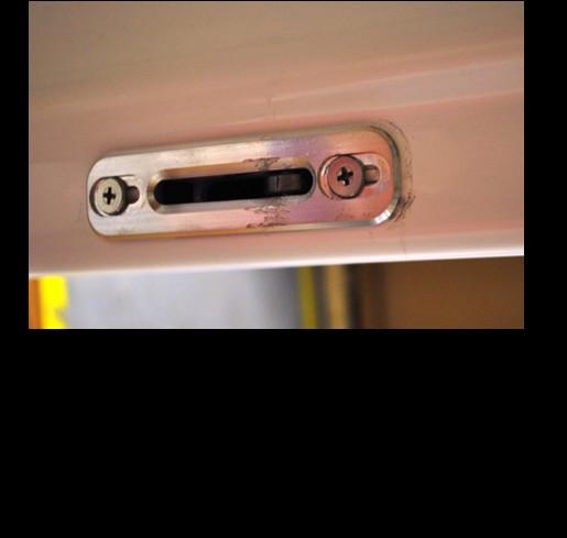
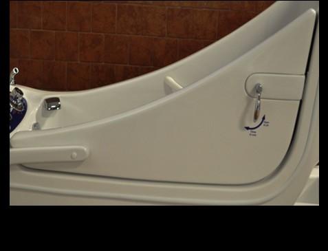
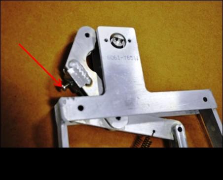
8 ADJUST RH4, RT4, RH6, RG9, RK12 AND RB14 DOOR TOOLS NEEDED: #3 AND #2 PHILLIPS SCREWDRIVER, 5/64 ALLEN WRENCH Turn set screw (which is on the bottom of the lock slide) 1 revolution clockwise. Check for leaks. If door still leaks repeat this step. 3


9 ADJUST AN RR7II DOOR TOOLS NEEDED: PHILLIPS SCREWDRIVER, 3/16 ALLEN WRENCH, PENCIL, SHIMS 4
 If the door moves down, refer to instructions below. RR7II- ADJUST DOOR TENSION TOOLS NEEDED: PHILLIPS SCREW DRIVER, 1/4 RATCHET DRIVE, 5/16 SOCKET 1) Ensure tub is in the lowest position.")
 Set the panel aside. KEEP TRACK OF ALL SCREWS. 6) Slightly tighten the 4 Phillips screws on the door hinge shown below. 7) Open door to a position between 1 and 2 o'clock.")
10 RR7II- CHECK DOOR TENSION 1) Ensure tub is in the lowest position. 2) Open door to a position between 1 and 2 o'clock. 3) Door should stay in place. 4) If the door moves down, refer to instructions below. RR7II- ADJUST DOOR TENSION TOOLS NEEDED: PHILLIPS SCREW DRIVER, 1/4 RATCHET DRIVE, 5/16 SOCKET 1) Ensure tub is in the lowest position. 2) Locate the front access panel. 3) Open the 4 hinged screw caps using a knife or small flat head screw driver. (See Figure 1) 4) Remove the 4 screws using a Phillips screw driver. 5) Set the panel aside. KEEP TRACK OF ALL SCREWS. 6) Slightly tighten the 4 Phillips screws on the door hinge shown below. 7) Open door to a position between 1 and 2 o'clock. 8) Repeat steps 6 and 7 until the door stays in the 1 to 2 o'clock position. The door should be easy to lift and close as well. FIGURE 1 5


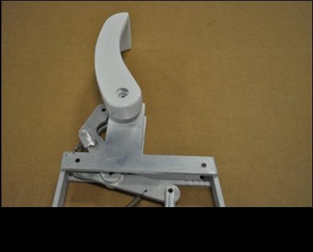
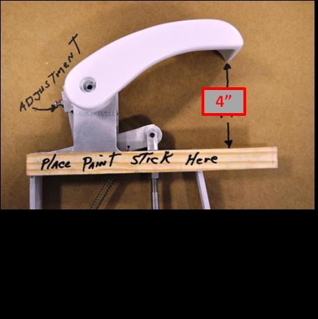
11 ADJUST RH4, RT4, RH6, RG9, RK12 AND RB14 DOOR HANDLE TOOLS NEEDED: PHILLIPS SCREWDRIVER, PAINT STICK 6


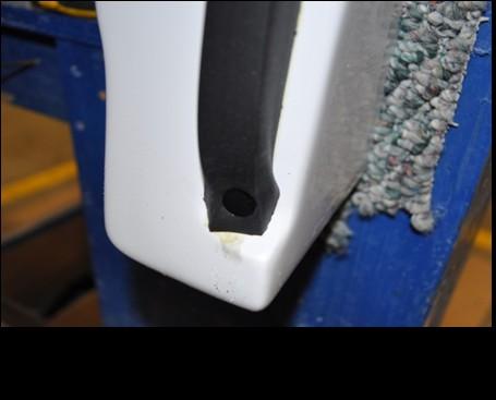
12 REPLACING A RH4, RT4, RH6, RG9, RK12 AND RB14 DOOR SEAL 7
 minutes).")

 hours before the first use.")
13 REPLACING AN RR7 DOOR SEAL CONTENTS OF DOOR SEAL Rubber Door Seal Two (2) Black Push Pins Contact Cement Sandpaper Brush INSTRUCTIONS 1. Using a paint brush, apply an even coat of glue to both the rough surface of seal and surface on the door. 2. Allow the glue on both surfaces to skin over (approximately five (5) minutes). 3. Beginning at one end of the seal, carefully place the seal into seal area of door taking care to make good contact between the door and seal. Be sure that the wide flat portion of seal is positioned as shown. Narrow Wide CORRECT POSITIONING INCORRECT POSITIONING INCORRECT POSITIONING 4.Use masking tape as necessary to help hold seal in place. 5.When entire seal is in place, taper ends as needed for proper fit and insert push pins at both ends of doors. 6.Use lacquer thinner on a towel to clean excess glue off the door surface. 7.Allow the glue to set for at least two (2) hours before the first use. NOTE: THE USE OF PETROLEUM BASED CLEANERS OR LUBRICANTS WILL CAUSE RUBBER DOOR SEAL TO FAIL. TO CLEAN AND MAINTAIN SEAL, USE MILD SOAP AND WATER OR PRODUCTS DESIGNED SPECIFICALLY FOR RUBBER PRODUCTS. 8


14 CLEANRANE TM AIR SPA The CleanRane Air-Spa System features spring loaded check valves with back flow prevention, eliminating the extra step to disinfect or flush the air lines. This provides the highest level of protection from bacteria and contaminants. When the system is turned off, the spring loaded check valves shut immediately, therefore, no water or debris can enter the air-spa lines. Simply disinfect the surface of the tub and air-spa jets, which kills the bacteria and contaminants. Rinse the tub and you re ready to go. The CleanRane Air Spa System features 12 jets strategically placed for maximum effect. 9
 ON/OFF BLOWER 1st")


15 AIR SPA BUTTON FUNCTIONS AIR SPA BUTTON ON/OFF BUTTON 1st press: Blower turns on at high speed 2nd press: Blower changes to lo speed 3rd press: Blower turns off AIR SPA KEYPAD (Discontinued- may be on older models) ON/OFF BLOWER 1st press: The blower starts 2nd press: The blower stops BLOWER SPEED ON / OFF BLOWER SPEED VARIATION 1st press: Press & hold to increase the blower speed, release pressure at desired speed 2nd press: Press & hold to lower the blower speed, release pressure at desired speed. PULSATION PULSATION MODES 1st press: Wave Speed will vary gradually from maximum to minimum 2nd press: Pulse Speed will go directly to minimum and then straight to maximum. 3rd press: Returns to maximum speed. 10
16 CHECK AIR SPA MOTOR MOUNTS 1) Open the disinfectant door and locate the Air Spa motor. (RR7II - Remove the front panel using a knife and Phillips screw driver) 2) Ensure the 3 bolts are secure. 3) Tighten with a 1/2" wrench. 11


17 CHECK AIR SPA BLOWER HOSE CLAMPS Hose clamps should be attached to air spa motor as shown. Hose clamps should be attached to manifold as shown. 12


, which secures the grey flexible hose to the Air Spa Motor. Do not remove the grey flexible hose.")
. Remove the Air Spa Motor, including the grey CAT5 cable.")
, which comes with the new Air Spa Motor.")

18 AIR SPA MOTOR REPLACEMENT TOOLS NEEDED: #2 PHILLIPS SCREWDRIVER, TWO 7/16 WRENCHES, PVC CEMENT, 5/16 SOCKET OR LARGE FLAT TIP SCREWDRIVER STEP 1: Remove access panel and unplug Air Spa Motor from GFCI outlet. STEP 2: Follow the grey CAT5 cable from the Air Spa Motor to the back of the Air Spa Keypad, press tab and remove. STEP 3: Using a 5/16 socket or large flat tip screwdriver, remove the hose clamp and self tapping screw (if installed), which secures the grey flexible hose to the Air Spa Motor. Do not remove the grey flexible hose. STEP 4: Using two 7/16 wrenches, remove Air Spa Motor mount nuts, bolts, and washers (top bolt and nut underneath). Remove the Air Spa Motor, including the grey CAT5 cable. STEP 5: Install new Air Spa Motor (see Step 4). Install new CAT5 cable and plug into the Air Spa Keypad (see Step 2), which comes with the new Air Spa Motor. STEP 6: Put a light coat of PVC Cement on the area where the grey flexible hose slides onto the Air Spa Motor. Re-attach the grey flexible hose to the Air Spa Motor. Using the 5/16 socket or large flat tip screwdriver, tighten the hose clamp that secures the grey flexible hose. Wipe off any excess PVC Cement. * Make sure there are no kinks or obstructions in the flexible grey hose, which can cause overheating leading to failure and/or damage to the Air Spa Motor. 13
19 AIR SPA MOTOR REPLACEMENT- RR7 TOOLS NEEDED: #2 PHILLIPS SCREWDRIVER, TWO 7/16 WRENCHES, PVC CEMENT, 5/16 SOCKET OR LARGE FLAT TIP SCREWDRIVER Make sure all is power is off to the tub. Open white cap screw covers and use a Phillips head screwdriver to remove 4 screws. Remove the back turtle access panel. Slowly bring panel out and unplug up/down button wires. Take a flat head screwdriver and remove 4 screws on gray junction box. Loosen black connectors on junction box. Pull out the wire connectors and disconnect the air spa wires. Cut the old air spa motor cord right beside old motor. Attach a rubber band to the old cord and the new air spa motor cord and pull cord thru to the other end of tub. Remove old air spa motor, by loosening up bolts on pump mount Place new air spa motor in tub and attach with bolts from old air spa motor. Cut end off of new air spa motor cord. Strip wires as needed. Attach wires in junction box with wire connectors, to correct color coding. Plug gray cord on tub in GFI outlet and test air spa motor. If motor works correctly refer to next step. If not make sure wires are hooked up correctly and wire connectors are tight. After motor is tested and working properly, replace gray junction box cover with 4 screws. Replace turtle shell cover on back of tub. Attach wires to the up/down buttons on tub. Replace 4 screws to white panel. Close white screw covers. 14


 to expose the internal parts of the jet assembly and remove the old brass insert and spring.")


20 AIR SPA JET REPLACEMENT TOOLS NEEDED: SMALL FLAT TIP SCREWDRIVER AND SMALL NEEDLE NOSE PLIERS STEP 1: Turn on air spa motor for 30 seconds to blow out any water in the assembly. STEP 2: Place the drain plug over drain hole or close cable drain to avoid any parts falling into the tub drain. Openings STEP 3: Using a small flat tip screwdriver, insert tip into one of the 6 small openings in the jet cover cap and gently pop off. Be careful not to damage gelcoat or nylon assembly. Using small needle nose pliers, remove the Y piece (see Fig. 1) to expose the internal parts of the jet assembly and remove the old brass insert and spring. Do not lose or throw out the Y piece, set aside. Y Piece Y Piece STEP 4: Make sure the jet assembly is free of debris, mildew, or any buildup before inserting new brass insert and spring. Clean with cotton swab if needed. Insert the new brass insert and spring into the existing jet assembly. Make sure the spring is installed directly in the center of the jet assembly. STEP 6: Insert the Y piece directly centered on the spring. Push down on the Y piece till it snaps into place. Spring must be centered to work properly (see above picture). Install jet cover cap. Press until you hear a snap noise indicating it s in the correct position. 15
21 AIR SPA FAQ s Can the air blower be installed anywhere other than under the bathtub? Yes, it can. The air blower can be installed up to 15 feet away from the bathtub. However, 1. Never insulate the blower. However, it is recommended to insulate the air hose to prevent cooling of the air circulating within. 2. The ambient air surrounding the air blower must be maintained at the same temperature as the room where the bathtub is installed. The blower was not designed to heat cold air from a basement or a garage. The blower starts on its own. Almost all air blowers are standard with a built in automatic purge cycle that will start 10 minutes after the use of the system. However, 1. If there is a power outage, the purge cycle could be activated. 2. If the system is equipped with a water detector, the purge cycle will start every time there is water in the bathtub (after you shower, after cleaning the bathtub, etc.). 3. If this happens often even if the system has not been used, contact your dealer. The keypad could be defective and will have to be replaced. The purge cycle does not start. First verify with your distributor to make sure that your blower is equipped with this option. If it is: 1. Verify that the power to your system does not go through a timer or a security switch. If the timer or switch was shut off before the purge cycle count down has finished, the blower will not turn on. 2. Verify that there is no water in the bottom of your bathtub. Your system may be equipped with a water detector that is preventing the purge cycle to start. Can the air blower be installed anywhere other than under the bathtub? Yes, it can. The air blower can be installed up to 15 feet away from the bathtub. However, 1. Never insulate the blower. However, it is recommended to insulate the air hose to prevent cooling of the air circulating within. 2. The ambient air surrounding the air blower must be maintained at the same temperature as the room where the bathtub is installed. The blower was not designed to heat cold air from a basement or a garage. The blower starts on its own. Almost all air blowers are standard with a built in automatic purge cycle that will start 20 minutes after the use of the system. However, 1. If there is a power outage, the purge cycle could be activated. 2. If the system is equipped with a water detector, the purge cycle will start every time there is water in the bathtub (after you shower, after cleaning the bathtub, etc.). 3. If this happens often even if the system has not been used, contact your dealer. The keypad could be defective and will have to be replaced. The purge cycle does not start. First verify with your distributor to make sure that your blower is equipped with this option. If it is: 1. Verify that the power to your system does not go through a timer or a security switch. If the timer or switch was shut off before the purge cycle count down has finished, the blower will not turn on. 2. Verify that there is no water in the bottom of your bathtub. Your system may be equipped with a water detector that is preventing the purge cycle to start. Unfortunately some people are more sensitive to this effect than others. The solution is to change positions in the bathtub and the sensation will diminish. 16
22 AIR SPA FAQ s (Continued) The purge cycle does not start. First verify with your distributor to make sure that your blower is equipped with this option. If it is: 1. Verify that the power to your system does not go through a timer or a security switch. If the timer or switch was shut off before the purge cycle count down has finished, the blower will not turn on. 2. Verify that there is no water in the bottom of your bathtub. Your system may be equipped with a water detector that is preventing the purge cycle to start. Unfortunately some people are more sensitive to this effect than others. The solution is to change positions in the bathtub and the sensation will diminish. The air blower functions but the options on my keypad do not always function. 1.If the problem is only with the «+» button; please note that your system starts at a maximum speed. Therefore, pressing this button will have no effect. To verify the proper function of your system press the button; the speed should go down. Then press the «+» button and the speed will increase. 2. If it is a problem with any other button, your keypad could be defective. Sometimes a humidity problem can occur within the electronic system if a wet cloth is left too long on the keypad or if the keypad label is cracked. Contact your distributor who will guide you through the procedure to have your keypad changed. I press on the air push button but the system does not turn on or off. With an air push button the solutions are quite simple most of the time. 1. If the button is hard to press or comes back too slowly to its initial position, there may be too much air accumulated within the hose. - To correct the problem, locate the transparent hose and with a thin pin, poke one or two holes through it to let the air out. (This will not harm your system in any way). - Verify that the hose is not kinked or bent preventing the air from flowing easily. 2. If the button is easy to manipulate, unplug the transparent hose from under the button and gently blow into it. - If the blower starts, the problem is in the air push button. - If the blower does not start, the problem is in the blower. In both cases, contact your distributor for the procedure to have the defective part replaced. Please inform them of your testing results. Nothing seems to work. 1. Check the main power box of the house if the breaker is at the ON position. 2. Check if the ground fault circuit interrupter (GFCI) has not tripped. Most manufactures test their products before it leaves the plant. Risks that nothing works are almost null. Interrupt the current for 15 seconds and then reconnect it. This should solve your problem. My ground fault circuit breaker switches off. 1. If your bathtub is equipped with both a whirlpool pump and an air blower, verify that each unit is connected to a separate ground fault circuit interrupter (GFCI). 2. Sometimes it can occur that the interrupter (GFCI) is too sensitive. To verify this, disconnect the blower and connect either a hair blower or a light bulb. If the ground fault circuit interrupter trips again, it may be that there is a short circuit somewhere in the electrical line. Have your electrician verify the problem. If the problem persists, the ground fault circuit should be replaced. 17

23 18


.")
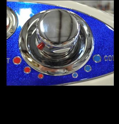
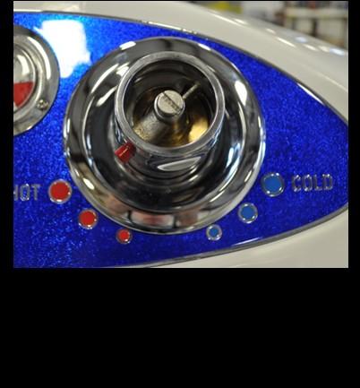
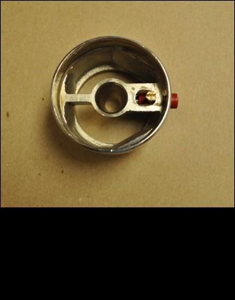
24 HOW TO REPLACE A TUB-FILL OR SHOWER DIVERTER VALVE STEM TOOLS NEEDED: CRESCENT WRENCH, SILICONE ADHESIVE, AND 17MM SOCKET (if needed) Figure 1 Step 1: Using both hands, grip the knob firmly. Pull firmly and steady to remove the knob. Step 2: Remove the chrome escutcheon and gently peel off the rubber gasket. Step 3: Using a crescent wrench, remove part A (fig.1). Hold the valve assembly firmly with your fingers. Step 4: Remove part B (fig.1). Simply pull straight out. 19
.")


25 HOW TO REPLACE A TUB-FILL OR SHOWER DIVERTER VALVE STEM (Continued) Step 5: Using a crescent wrench, remove part C (fig.1). Step 7: Using a crescent wrench, remove part E (fig.1). Step 10: Use tongue & groove pliers on base of valve stem and tighten until it stops. Be careful not to over tighten and snap the stem. Step 8: Use tongue & groove pliers on base of valve stem and remove. Step 11: Re-install part E (fig.1). Note: Do not over tighten. Step 13: Using a crescent wrench, Re-install part C (fig.1)/ Step 6: Remove part D (fig.1). Step 9: Insert and carefully thread in new valve stem. Hand tighten. Step 12: Re-install part D (fig.1)/ Step 14: Re-install part B (fig1). 20


.")

26 HOW TO REPLACE A TUB-FILL OR SHOWER DIVERTER VALVE STEM (Continued) Step 15: Re-install part A (fig.1). Hand tighten until it stops, then using the crescent wrench, tighten 2 full turns. Note: Do not over tighten. If turning the valve on and off is stiff or makes a grinding noise, the nut is too tight. Back off by loosening a 1/2 to 1 turn. The valve should be fluid and easy to turn on and off. Step 16: Re-install the chrome escutcheon and rubber gasket. Note: If rubber gasket loses its adhesive backing during removal in Step 2, use a small bead of silicone adhesive around the entire rubber gasket. Wipe off any excess silicone. Step 17: Align the teeth inside the knob with the teeth on part B (fig.1). Using the palm of your hand, push in the knob firmly until it locks into place. Note: If knob doesn t lock into place, use a small amount of shampoo or body wash on the teeth for lubrication. Note: If the valve stem is broken off, use either a 17mm socket or channel locks to remove it. Remove all of the parts (A-E on fig.1) from the broken valve and begin at Step 9. If parts cannot be removed from the broken valve, you ll need to order the complete valve package (item # /2 shower valve or # /4 tub-fill valve). 21


27 CALIBRATING PROCEDURE TO MAKE WATER TEMPERATURE HOTTER TOOLS NEEDED: CRESCENT WRENCH AND FLATHEAD SCREWDRIVER 22

28 THERMOSTATIC MIXING VALVE HANDLE ASSEMBLY TOOLS NEEDED FOR INSTALLATION: SMALL FLAT TIP SCREWDRIVER, LARGE FLAT TIP SCREWDRIVER 23


29 THERMOSTATIC MIXING VALVE CARTIDGE REMOVAL TOOLS NEEDED: SMALL FLAT TIP SCREW DRIVER, LARGE FLAT TIP SCREW DRIVER, CRESCENT WRENCH AFTER REMOVING CARTRIDGE, SOAK IN 1 TBSP BAKING SODA PER 8 OZ WATER. 24
 Turn the disinfectant valve to the disinfectant position.")
 The smaller container should lose approximately 2oz for every gallon jug filled.")

30 CHECK DEMA FUNCTION 1) Fill a container up with water and insert the DEMA valve hose. 2) Turn the disinfectant valve to the disinfectant position. 3) Fill an empty gallon jug up using the disinfectant sprayer. 4) The smaller container should lose approximately 2oz for every gallon jug filled. 5) If this is not the case, then use a small straight (flat tip) screw driver to adjust the flow rate on the DEMA Valve. The adjustment screw is shown below. Turn counter-clockwise to pull more disinfectant. 25


31 CLEANING A DEMA VALVE TOOLS NEEDED: ADJUSTABLE WRENCH, 3/32 ALLEN WRENCH, FLATHEAD SCREWDRIVER STEP 1: Turn cold water supply off and identify the Disinfectant Valve System, which consists of a Metering Knob Assembly and Disinfectant Injector. STEP 2: Remove the knob using a 3/32 Allen wrench. Remove the large nut holding the 3-way Valve in place with an Adjustable wrench. Simply pull or push the disinfectant valve system out of the hole, which will allow easy access for the repair/cleaning. Metering Knob Assembly Disinfectant Injector STEP 3: Remove the clear hose that goes from the Metering Knob Assembly to the disinfectant bottle. Run hot water through the hose and filter on the end to remove debris or build-up. STEP 4: Label or mark the hoses to insure they are reconnected correctly. Remove the hoses using the quick disconnects and/or compression nut (Adjustable wrench needed). * Removing the hoses is not required, however, it makes it easier to perform the task. 26


32 REPLACING A CHECK VALVE TOOLS NEEDED: ADJUSTABLE WRENCH AND TEFLON TAPE STEP 1: Shut off main water supply and locate the Brass T that branches off the main cold water supply and feeds the disinfection system. STEP 2: Disconnect hose coming into the Brass T from the main cold water supply. Quick Connect Brass T Check Valve New Check Valve Arrow towards Brass T STEP 3: Disconnect hoses that lead to the disinfection system. Remove quick connect from Check Valve. Remove Check Valve from Brass T. Hoses to Disinfection System STEP 4: With teflon tape, wrap quick connect threads and screw tightly into Check Valve, then wrap Check Valve threads and screw tightly into the Brass T with arrows pointing towards Brass T. DO NOT OVER TIGHTEN. STEP 5: Reconnect hoses that lead to disinfection system back into quick connects as shown above. Reconnect the hose that leads to the main cold water supply. Turn on main water supply and check for leaks. 27
 Ensure tub is in the highest position. 2) Open the disinfectant cabinet.")
33 CHECK ACTUATOR MOUNT - RR7II 1) Ensure tub is in the highest position. 2) Ensure the actuator mount under the tub is securely fastened. 3) If it is not, (2) 9/16" wrenches to tighten. The nuts are accessible from under the base. CHECK ACTUATOR MOUNT - RS8 1) Ensure tub is in the highest position. 2) Open the disinfectant cabinet. 3) Using a flashlight, ensure the actuator bolts and pins are securely fastened. 4) If it is not, (2) 9/16" wrenches to tighten. The nuts are accessible from under the base. 28
 Ensure tub is in the lowest position if possible.")
 Remove white screw caps with a small flat head screw driver.")
 Unhinge the 4 screw caps on the rear panel and remove using a Phillips screw driver.")
34 RR7II ACTUATOR REPLACEMENT PARTS NEEDED: TOOLS NEEDED: ACTUATOR PHILLIPS SCREW DRIVER 1/4 RATCHET DRIVE 5/16 BOARD OR SIMILAR TO USE AS A PROP PROCEDURE: 1) Ensure tub is in the lowest position if possible. 2) Locate the actuator access just above the disinfectant door. 3) Remove white screw caps with a small flat head screw driver. 4) Using a ¼ Ratchet Drive and the 5/16" Socket, remove the 4 hex head screws from the access panel. Set aside. 5) Unhinge the 4 screw caps on the rear panel and remove using a Phillips screw driver. SET ASIDE WITHOUT UNPLUGGING THE BUTTON WIRE LEADS 6) Remove the retainer clip 7) Unplug the actuator cable as from the control box: shown below: Press the 3 tabs to release. Actuator Cable 29


 Remove the upper clevis pin and 2 washers from the actuator. 12) Pull the actuator from the bath tub.")
 Remove the board or prop and let down slowly. 16) Install the lower clevis pin, 2 washers, and cotter pin.")
35 RR7II ACTUATOR REPLACEMENT (Continued) 8) Remove the lower clevis pin and 2 washers from the actuator. Do this by pulling the cotter pin from it. 9) Unhinge the 4 screw caps on the front panel and remove using a Phillips screw driver. SET ASIDE AND KEEP TRACK OF SCREW COVERS. 10) Lift the front of the tub where shown below and place a 2x4 board or similar to keep propped up. 11) Remove the upper clevis pin and 2 washers from the actuator. Do this by pulling the cotter pin from it. 12) Pull the actuator from the bath tub. 13) Install the new actuator as shown here. 14) Install the lower clevis pin, 2 washers, and cotter pin. 15) Remove the board or prop and let down slowly. 16) Install the lower clevis pin, 2 washers, and cotter pin. 17) Reroute the new actuator cable and plug it in. 18) Re-install the retainer clip. 19) Re-install rear panel. 20) Test the actuator to insure proper functionality. 21) Reinstall front panel. 22) Reinstall actuator access panel. 30


36 RS8 ACTUATOR REPLACEMENT TOOLS NEEDED: SMALL PLIERS, 2 x 4 x 12 WOOD BOARD, #2 PHILLIPS HEAD SCREWDRIVER PARTS NEEDED: ACTUATOR Actuator Actuator Piston Wood Board STEP 1: Remove back panel (6 screws and white cap covers). Raise the tub to the highest position. STEP 2: Put 2 x 4 x 12 wood board in place and lower tub until weight is on board and pressure is off of actuator. Actuator Plugin STEP 3: Locate the Control Box. Locate the Connector Clip that holds the Actuator Plug in place. Remove Connector Clip by pressing tabs on each end. Unplug Actuator Plug. Lower Clevis Pin Top Clevis Pin STEP 4: Remove the cotter pin/hairpin from both top and bottom clevis pins with small pliers. Remove the top clevis pin and washers first, then remove lower clevis pin and washers. Remove the defective Actuator. STEP 5: Install the top of the new Actuator with clevis pin, washers, and cotter pin/hairpin. Connect Actuator Plug-In and install the Connector Clip. Press the raise button to lower the bottom of the Actuator to align with the bottom Actuator mount. When properly aligned, install the bottom clevis pin, washers, and cotter pin/hairpin. STEP 6: Raise the tub to the highest position and remove the 2 x 4 x 12 wood board. Raise and lower tub to test if Actuator is working properly. Lubricate Actuator Piston with white lithium grease (see Step 1). STEP 7: Install back panel (6 screws and white cap covers). 31


37 CABLE DRAIN CORRECTION / ADJUSTMENT STEP 1: Using a Phillips head screwdriver, remove set screw. STEP 2: Remove cable drain handle STEP 3: Use a wrench to remove nut and place as shown in Step 4. STEP 4: This is the correct way the plate sits. CORRECT INCORRECT * When replacing the plate and nut, make sure the nut is secure. STEP 5: Make sure handle moves freely and does not rub the finish on the tub. If handle is too tight, remove handle and readjust the nut tighter. 32


38 REPAIR DRAIN STOP / SET SCREW ASSEMBLY 33
39 Trouble Shooting Institutional Symptoms Check Solutions Water too hot or cold when using the thermostatic mixing valve controls Check to ensure the water supplies (hot & cold) are within 10% of each other Check hot & cold inlet connections. Check to ensure hot & cold supply lines are installed correctly Check thermostatic mixing valve cartridge. Check the maximum temperature setting. Consult licensed plumber Shut off hot & cold supply valves, disconnect supply hoses, and ensure supply hose screens are free of debris Reverse connections if backwards Shut off hot & cold supply valves, remove cartridge from body and soak in a cleaning solution overnight, re-install and test Contact a RANE authorized dealer for calibration instructions Air Spa does not turn on Check GFCI Check 15A breaker Check that the motor is plugged into the GFCI Check that the grey cord is connected to the motor and keypad Reset if necessary Reset if necessary Plug in if necessary Re-attach if necessary Air Spa jets not working, but can hear the motor running Check to ensure the grey flew hose is connected between the motor and the manifold Re-attach if necessary with a 1 ½ hose clamp Door swings closed by itself Check gas shock for compression Check screws are tight on the inner and outer hinge bushings If replacement needed, contact RANE authorized dealer for replacement parts Tighten with a Phillips screw driver if loose Door will not latch Check door handle and mechanism are functioning properly If replacement needed, contact RANE authorized dealer for replacement parts Door will not release Check door seal for soap build up Clean seal with mild soap and water solution, then pat dry. Apply a rubber dressing 34
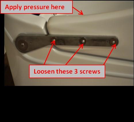
40 Trouble Shooting Institutional (Continued) Symptoms Check Solutions Water leaking from door area Check adjustment on door latch bearing Check door positioning is equal around the tub rim and seal Check door seal Loosen the 2 Phillips screws and slide the bearing assembly down 1/8 at a time to make door shut tighter Remove hinge cover and loosen the 3 button head screws attached to the door as necessary Re-attach if loose with contact cement, suitable for fiberglass. If replacement needed, contact RANE authorized dealer for replacement parts No disinfectant dispensing Check to ensure there is disinfectant in the bottle Check to ensure the clear disinfectant hose is inserted into the bottle Check to ensure the clear disinfectant hose is not clogged Check adjustment on the DEMA valve Fill if necessary Insert into bottle if necessary Clean hose and re-attach Adjust small flat tip screw counterclockwise for more, and clockwise for less RR7II Tub will not tilt Check GFCI Check 15A breaker Check momentary switches for continuity Check control box on back of tub has power Check all connections going to the control box Reset if necessary Reset if necessary If replacement needed, contact RANE authorized dealer for replacement parts Carefully remove back cover and prevent breakage of the momentary switch wires. Check the clear circular window on the control box for the light to be green Ensure all connections are plugged into the control box, and attach if removed RR7II Tub making grinding noise when tilted back and forth Check actuator to be the grinding noise If replacement needed, contact RANE authorized dealer for replacement parts 35
41 Trouble Shooting Institutional (Continued) Symptoms Check Solutions RS8 Tub will not raise or lower Check GFCI Check 15A breaker Check that the tub is plugged into the GFCI Check momentary switches for continuity Check control box on back of tub has power Reset if necessary Reset if necessary Plug in if necessary If replacement needed, contact RANE authorized dealer for replacement parts Carefully remove back cover and prevent breakage of the momentary switch wires. Check the clear circular window on the control box for the light to be green Check all connections going to the control box Ensure all connections are plugged into the control box, and attach if removed Make sure the supply lines are not switched Switch the Supply Lines Thermostatic Mixing Valve is acting erratically The supply line screens may be clogged The mixing valve cartridge may by clogged Disconnect the supply lines and clean the screens Refer to the cartridge removal procedure Soak the cartridge 24hrs in a high concentration of CLR Contact your dealer for a cartridge replacement 36
42 UPGRADES RR7II RECLINE BUTTON REPLACEMENT PARTS NEEDED: 4 - FEMALE SLIP-ON QUICK SPADE LUG CONNECTORS 2 - BUTTONS TOOLS NEEDED: 1 - WIRE CRIMPS 1 - PHILLIPS SCREW DRIVER 1 - OPE END ADJUSTABLE WRENCH PROCEDURE: 1) Remove white screw caps with a small flat head screw driver 2) Remove 4 Phillips screws from the rear cover. 3) Remove the cover and set aside. KEEP TRACK OF ALL SCREWS. 4) Push the 2 actuator buttons out of the mounting holes. 5) Disconnect the 4 female quick connects from the button lugs. 6) Replace the 4 female quick connects with the provided quick spade lug connects. 7) Remove the mounting nut from each replacement button. 8) Push the buttons into the holes. 9) Tighten the mounting nuts from the back side. 10) Connect the orange & red wire to the 'LOWER' button and green & red wire to the 'RAISE' button. 11) Test the buttons to ensure proper functionality. 12) Re-mount the rear cover using the 6 mounting screws. 37
 Remove white screw caps with a small flat head screw driver 2) Remove 4 Phillips screws from the rear cover. 3) Remove the cover and set aside.")
 Replace the 4 female quick connects with the provided quick spade lug connects. 7) Remove the mounting nut from each replacement button. 8) Push the buttons into the holes.")
43 UPGRADES RR7II AUTO FILL BUTTON REPLACEMENT PARTS NEEDED: 4 - FEMALE SLIP-ON QUICK SPADE LUG CONNECTORS 2 - BUTTONS TOOLS NEEDED: 1 - WIRE CRIMPS 1 - PHILLIPS SCREW DRIVER 1 - OPEN END ADJUSTMENT WRENCH PROCEDURE: 1) Remove white screw caps with a small flat head screw driver 2) Remove 4 Phillips screws from the rear cover. 3) Remove the cover and set aside. Keep track of all screws 4) Push the 2 Auto Fill buttons out of the mounting holes. 5) Disconnect the 4 female quick connects from the button lugs. 6) Replace the 4 female quick connects with the provided quick spade lug connects. 7) Remove the mounting nut from each replacement button. 8) Push the buttons into the holes. 9) Tighten the mounting nuts from the back side. 10) Connect the orange & red wire to the 'STOP' button and green & red wire to the 'START' button. 11) Test the buttons to ensure proper functionality. 12) Re-mount the rear cover using the 6 mounting screws. OLD BUTTON NEW BUTTON 38
 Remove white screw caps with a small flat head screw driver 2) Remove 6 Phillips screws from the rear cover.")
44 RS8 HEIGHT ADJUST 2-BUTTON REPLACEMENT PARTS NEEDED: 4 - FEMALE SLIP-ON QUICK SPADE LUG CONNECTORS 2 - BUTTONS 2 - WIRE TIES TOOLS NEEDED: 1 - WIRE CRIMPS 1 - PHILLIPS SCREW DRIVER 1 - DIAGONAL CUTTERS 1 - OPEN END ADJUSTABLE WRENCH UPGRADES PROCEDURE: 1) Remove white screw caps with a small flat head screw driver 2) Remove 6 Phillips screws from the rear cover. 3) Remove the cover and set aside. KEEP TRACK OF ALL SCREWS. 4) Remove 2 Phillips screws from the battery pack. Allow battery pack to hang from tub 5) Use diagonal cutters to remove 2 wire ties from the Air Spa manifold (if equipped). Allow Air Spa manifold to hang free 6) Push the 2 actuator buttons out of the mounting holes. 7) Disconnect the 4 female quick connects from the button lugs. 8) Replace the 4 female quick connects with the quick spade lug connects. 9) Remove the mounting nut from each replacement button. 10) Push the buttons into the holes. 11) Tighten the mounting nuts from the back side. 12) Connect the orange & red wire to the 'LOWER' Button and green & red wire to the 'RAISE' button. 13) Test the buttons to ensure proper functionality. 14) Use the provided wire ties to re-mount the Air Spa manifold. 15) Re-mount battery pack using the 2 mounting screws. 16) Re-mount rear cover using the 6 mounting screws. 39
 Remove white screw caps with a small flat head screw driver 2) Remove 6 Phillips screws from the rear cover. 3) Remove the cover and set aside. KEEP TRACK OF ALL SCREWS.")
45 RS8 HEIGHT ADJUST 4-BUTTON REPLACEMENT UPGRADES PARTS NEEDED: 8 - FEMALE SLIP-ON QUICK SAPDE LUG CONNECTORS 4 - BUTTONS TOOLS NEEDED: 1 - WIRE CRIMPS 1 - PHILLIPS SCREW DRIVER 1 - OPEN END ADJUSTABLE WRENCH PROCEDURE: 1) Remove white screw caps with a small flat head screw driver 2) Remove 6 Phillips screws from the rear cover. 3) Remove the cover and set aside. KEEP TRACK OF ALL SCREWS. 4) Push the 4 actuator buttons out of the mounting holes. 5) Disconnect the 8 female quick connects from the button lugs. 6) Replace the 8 female quick connects with the provided quick spade lug connects. 7) Remove the mounting nut from each replacement button. 8) Push the buttons into the holes. 9) Tighten the mounting nuts from the back side. 10) Connect the orange & red wire to the 'LOWER' button and green & red wire to the 'RAISE' button. 11) Test the buttons to ensure proper functionality. 12) Re-mount the rear cover using the 6 mounting screws. 40
46 RS8 AUTO FILL BUTTON REPLACEMENT UPGRADES PARTS NEEDED: 4 - FEMALE SLIP-ON QUICK SPADE LUG CONNECTORS 2 - BUTTONS TOOLS NEEDED: 1 - WIRE CRIMPS 1 - PHILLIPS SCREW DRIVER 1 - OPEN END ADJUSTABLE WRENCH PROCEDURE: 1) Remove white screw caps with a small flat head screw driver 2) Remove 6 Phillips screws from the rear cover. 3) Remove the cover and set aside. KEEP TRACK OF ALL SCREWS. 4) Push the 2 Auto Fill buttons out of the mounting holes. 5) Disconnect the 4 female quick connects from the button lugs. 6) Replace the 4 female quick connects with the provided quick spade lug connects. 7) Remove the mounting nut from each replacement button. 8) Push the buttons into the holes. 9) Tighten the mounting nuts from the back side. 10) Connect the orange & red wire to the 'STOP' button and green & red wire to the 'START' button. 11) Test the buttons to ensure proper functionality. 12) Re-mount the rear cover using the 6 mounting screws. 41


47 UPGRADES RR7-II, RK12, RG9, RB14 THERMOMETER REPLACEMENT PROCEDURE PARTS NEEDED: 1 - THERMOMETER TOOLS NEEDED: 1 - WIRE CRIMPS, 1 - PHILLIPS SCREW DRIVER, 1-11/16" WRENCH, 1-7/8" WRENCH STEP 1: Turn cold water supply off and identify the Disinfectant Valve System, which consists of a Metering Knob Assembly and Disinfectant Injector. 3 Screws STEP 2: Using the 11/16 wrench, remove the smaller bushing first. Pull out the smaller bushing and probe. Remove larger adapter bushing with 7/8 wrench. See Fig. 1 STEP 3: Remove the 3 small Phillips head screws and pull out thermometer body and probe. Adapter Bushing FIGURE 1 Small Bushing & Probe Adapter Bushing STEP 4: Wrap new Adapter Bushing threads with Teflon tape and insert into copper threaded pipe using 7/8 wrench. Tighten well. STEP 5: Insert new thermometer body and probe through faceplate. STEP 6: Wrap small bushing threads with Teflon tape and insert probe and small bushing (fig. 1) into adapter bushing. Tighten with 11/16 wrench. STEP 7: Insert 3 small Phillips head screws that secure thermometer body to faceplate, see Step 3. STEP 8: Turn main water supply on. Test for leaks at bushings. If leak occurs, try tightening more. If leak still occurs, turn main water supply off and repeat Step 4 and Step 6. STEP 9: Re-install access panel. 42
 Remove 6 Phillips screws from the rear cover. 3) Remove the cover and set aside.")
 Using the 7/8 and the 11/16 wrenches, turn the thermometer fitting counter clockwise to remove. 7) Remove thermometer.")
 Apply Teflon tape (thread sealant) to the male threads only of the brass threaded bushing. This is the larger fitting. 12) Insert and tighten.")
48 RS8 THERMOMETER REPLACEMENT PROCEDURE UPGRADES PARTS NEEDED: 1 - THERMOMETER TOOLS NEEDED: 1 - WIRE CRIMPS 1 - PHILLIPS SCREW DRIVER 1-11/16" WRENCH 1-7/8" WRENCH PROCEDURE: 1) Remove white screw caps with a small flat head screw driver 2) Remove 6 Phillips screws from the rear cover. 3) Remove the cover and set aside. Keep track of all screws 4) Remove 3 Phillips screws from the thermometer housing. 5) Remove Phillips screws from the Control Box. ALLOW CONTROL BOX TO HANG FROM THE TUB. 6) Using the 7/8 and the 11/16 wrenches, turn the thermometer fitting counter clockwise to remove. 7) Remove thermometer. 8) Clean flange surface with a cleaner, such as glass cleaner or rubbing alcohol. 9) Insert new thermometer into the mounting hole. 10) Re-install the 3 mounting screws. 11) Apply Teflon tape (thread sealant) to the male threads only of the brass threaded bushing. This is the larger fitting. 12) Insert and tighten. 13) Apply Teflon tape (thread sealant) to the male threads only of the brass thermometer fitting. 14) Insert and tighten. 15) Re-install the Control Box. 16) Re-install the rear cover. 43
. 2.")


49 INSTALL A DISINFECTANT WAND UPGRADE KIT (# 1904+H) INSTALLATION: RG9 1. Place mounting bracket behind white disinfectant tray as shown in Figure 1a & 1b. Make sure the mounting bracket is snug against the top and side lip of the white disinfectant tray, which helps hold it in place (see Figure 1b). 2. Mark the location of the hole in the mounting bracket as shown in Figure 1b. 3. Drill a 3/16 hole through the mounting bracket and white disinfectant tray. 4. Using the screw and kept nut provided, assemble as shown in Figure 1a & 1b. 5. Install and hand tighten snuggly the disinfectant hose fitting and washer to the wand. 6. Using an adjustable wrench, tighten the red coiling disinfectant hose to the disinfectant hose fitting. * Teflon plumbing tape may be needed on the threads at the end of the red coiling disinfectant hose if a leak occurs.* Mounting Bracket **Make sure mounting bracket is snug against top and side lip Drill 3/16 hole here Disinfectant Tray FIGURE 1a Disinfectant Hose Fitting FIGURE 1b INSTALLATION: RR7 1. Remove the existing mounting bracket. 2. Using the screw and kept nut provided, replace and assemble the new mounting bracket as shown in Figure 2a. 3. If there is not an existing mounting bracket, align the mounting bracket on the side of the disinfectant cabinet you prefer and drill a 3/16 hole through the mounting bracket and lip of the cabinet. 4. Install and hand tighten snuggly the disinfectant hose fitting and washer to the end of the wand as shown in Figure 2b. 5. Using an adjustable wrench, tighten the end of the red coiling disinfectant hose to the disinfectant hose fitting. * Teflon plumbing tape may be needed on the threads at the end of the red coiling disinfectant hose if a leak occurs. * Mounting bracket can be installed on either side. FIGURE 2b Mounting Bracket Washer FIGURE 2a Disinfectant Hose Fitting 44

50 INSTALL A DISINFECTANT WAND UPGRADE KIT (# 1904+H) (Continued) INSTALLATION: RS8, RK12, & RB14-IM 1. Open the white hinged screw caps on the rear access panel (RS8 and RK12). 2. Remove rear access panel using a Phillips screwdriver. 3. Remove the old wand holster. 4. Mount the new holster, using the existing hole in the fiberglass, with the wider opening pointing up and the narrower opening pointing down (holster is tapered). Mark the second hole that needs to be drilled. 5. Drill a 3/16 hole through the fiberglass. 6. Use the remaining screw, washer, and kept nut provided, assemble as shown in Figure Reassemble the rear access panel (RS8, RK12). 8. Install and hand tighten snuggly the wand and washer directly into the existing disinfectant wand hose. FIGURE 3 Wider Opening Washer Narrower Opening 45
51 RANE Parts & Solutions 46
52 RANE Parts & Solutions (Continued) 47
53 RANE Parts & Solutions (Continued) 48

54 RANE Parts & Solutions (Continued) 49
THANK YOU FOR CHOOSING BATHERBOX GETTING STARTED WHAT S IN THE BOX? N. Northview Ave Sioux Falls, SD 57107
 INSTRUCTION MANUAL THANK YOU FOR CHOOSING BATHERBOX You are on your way to creating an unmatched bathing experience both for you and the lucky animal. The BatherBox is designed to save you hours of time
PACIFIC Recumbent Height-Adjustable Bath System Parts Breakdown and Assembly Manual
 PACIFIC Recumbent Height-Adjustable Bath System 9700 Parts Breakdown and Assembly Manual Panel 390010-1 Tubs 390011-1 or 390022-1 390748 Revision H 4/1/2014 PENNER PATIENT CARE, INC Box 523 / 101 Grant
Cascade Comfort Bathing Systems with Aqua-Aire Parts Breakdown & Assemblies
 Cascade Comfort Bathing Systems with Aqua-Aire Parts Breakdown & Assemblies PENNER PATIENT CARE INC. Box 523 / 101 Grant St. Aurora, NE 68818 SPAS MODEL NUMBERS- 560010-X, 560010-XL (X REPRESENTS A COLOR
Installation Instructions
 ARIANA IN WALL PRESSURE BALANCING BATH AND SHOWER SETS Installation Instructions 0 0 Thank you for selecting American-Standard...the benchmark of fine quality for over 00 years. To ensure that your installation
INSTALLATION INSTRUCTIONS
 INSTALLATION INSTRUCTIONS Universal Air Series!! NOTE!! Covers the following model: 6000 Series 85-0100B-AZ Rev 0 5/07 To ensure that the system is installed properly, provide your electrician with these
3.1 DISPENSER BLACK SHADOW SERIES. Tools Needed for Mounting SCS Dispenser Hammer
 SCS 2 BLACK SHADOW SERIES 3.1 DISPENSER ALWAYS OBSERVE PRODUCT SAFETY AND HANDLING INSTRUCTIONS. ALWAYS DIRECT DISCHARGE AWAY FROM YOU or other persons. ALWAYS DISPENSE CLEANERS AND CHEMICALS AS DIRECTED
Installation Manual TWM Performance Short Shifter Cobalt SS/SC, SS/TC, HHR SS, Ion Redline and Saab 9-3
 Page 1 Installation Manual TWM Performance Short Shifter Cobalt SS/SC, SS/TC, HHR SS, Ion Redline and Saab 9-3 Please Note: It is preferable to park on a flat surface, as you will have to engage and disengage
WARNING. Important Notice
 CAL (Color AquaLuminator ) Light and Return Water Flow for Above Ground Pools Owners Manual IMPORTANT SAFETY INSTRUCTIONS READ AND FOLLOW ALL INSTRUCTIONS SAVE THESE INSTRUCTIONS Table of Contents SECTION
Tools Needed for Mounting Cleá Filling Station
 ALWAYS OBSERVE PRODUCT SAFETY AND HANDLING INSTRUCTIONS. ALWAYS DIRECT DISCHARGE AWAY FROM YOU or other persons. ALWAYS DISPENSE CLEANERS AND CHEMICALS AS DIRECTED ON THE LABEL. ALWAYS DISPENSE INTO APPROVED
Cascade. Aqua-Aire. Standard & Swivel Lift Spas, Optional Reservoir. Parts Breakdown & Assemblies Right, Left, and End Tub Access Door Systems
 Cascade Aqua-Aire Standard & Swivel Lift Spas, Optional Reservoir Parts Breakdown & Assemblies Right, Left, and End Tub Access Door Systems X= Color, L- Left, W= Wide, T= Swivel Lift TUBS: 360010-X, 360010-XL,
Rollstar Shade Installation Instructions
 Rollstar Shade Installation Instructions All Lifting Systems Inside or Outside Mount Thank you for purchasing your new Rollstar shade. It has been custom-made from the highest quality materials to the
Installation Instructions
 BERWICK / BOULEVARD MONOBLOCK LAVATORY FAUCET with Speed Connect Drain Installation Instructions 70.0 7.0 Congratulations on purchasing your American Standard faucet with Speed Connect drain, a feature
ELECTRICAL SYSTEM UPGRADE
 NEW CONTROLLER & ELECTRICAL SYSTEM UPGRADE FOR DAIRY TECH, INCORPORATED 10, 30 & 60G PASTEURIZERS Parts to Include 2 Wire ties (Nuts) 2 sticky wire mount pads Large Rubber Grommet (for bottom of electric
Installation Instructions
 Installation Instructions SELECTRONIC PROXIMITY TOILET CONCEALED FLUSH VALVE. &. GPF Certified to comply with ASME A..M 00 AS America, Inc. Concealed Flushometer for -/" Top or Back Spud Bowls MODEL NUMBERS
Marsh Shipping Supply Co. LLC. Marsh TD2100 Electric Taper Technical Manual
 Marsh Shipping Supply Co. LLC Marsh TD2100 Electric Taper Technical Manual 2 A wall-socket must be close to the product and readily accessible. The overall system is protected against overload by the branch
Section 7 - Troubleshooting Guide
 Section 7 - Troubleshooting Guide Section 7 - Troubleshooting Guide IMPORTANT While this troubleshooting guide provides information to aid in troubleshooting problems with the range, it does not contain
Installation Instructions
 COLONY/COLONY SOFT Bidet Faucet and Transfer Valve with Speed Connect Drain Congratulations on purchasing your American Standard faucet with the Speed Connect drain, a feature found only on American Standard
INSTALLATION INSTRUCTIONS. Solid-State Series !! NOTE!! Covers the following models: Refer to INSERT for additional information
 INSTALLATION INSTRUCTIONS Solid-State Series!! NOTE!! Covers the following models: " CS6100 - CS7100 " CS6200 - CS9200 " CS6220 - CS9220 " CS6230 - CS9230 " CS6500 - CS7500 " CS6330 - CS9300 " CS9400 -
Installation Instructions JASMINE Spread Lavatory Faucet with the EverClean Finish & Speed Connect Drain
 Installation Instructions JASMINE 80. Spread Lavatory Faucet with the EverClean Finish & Speed Connect Drain Congratulations on purchasing your American Standard faucet with the EverClean finish and Speed
Part# JL AIR IT UP 4 Tire On Board Air Delivery System. (Requires External Air Source)
") Part# 18-1819 JL AIR IT UP 4 Tire On Board Air Delivery System (Requires External Air Source) The most up-to-date instructions always visit www.updownair.com www.updownair.com 833-226-4863 I M P O R T
Part# 18-1819 JL AIR IT UP 4 Tire On Board Air Delivery System (Requires External Air Source) The most up-to-date instructions always visit www.updownair.com www.updownair.com 833-226-4863 I M P O R T
SERIN MONOBLOCK LAVATORY FAUCET with
 SERIN MONOBLOCK LAVATORY FAUCET with Speed Connect Drain Installation Instructions 0.0 Congratulations on purchasing your American Standard faucet with Speed Connect drain, a feature found only on American
Procharger Stage II Intercooled Supercharger System (11-14 GT)
") Procharger Stage II Intercooled Supercharger System (11-14 GT) Installation Time: Approximately one day. Installed on 2012 Mustang GT 5.0/Manual Required Tools 3/8 Socket Set (Standard and Metric) 1/2
Procharger Stage II Intercooled Supercharger System (11-14 GT) Installation Time: Approximately one day. Installed on 2012 Mustang GT 5.0/Manual Required Tools 3/8 Socket Set (Standard and Metric) 1/2
INSTALLATION INSTRUCTIONS
 INSTALLATION INSTRUCTIONS Part# 22-7810 Add On Kit for Your ADS System Contents: Complete Install Kit for Your ARB CKMTA12V Compressor For the most up-to-date instructions please visit www.updownair.com
Installation Instructions Series
 PORTSMOUTH MONOBLOCK LAVATORY FAUCET with Speed Connect Drain Installation Instructions 70.0 7.0 Series 7.0 Congratulations on purchasing your American Standard faucet with Speed Connect drain, a feature
Installation Instructions
 TIMES SQUARE Spread Lavatory Faucet with Speed Connect Drain Installation Instructions 8.80 8.8 Congratulations on purchasing your American Standard faucet with Speed Connect drain, a feature found only
HYDRAULICS. TX420 & & lower. Hydraulic Tandem Pump Removal. 4. Remove the LH side panel (Fig. 0388).
.") TX420 & 425 240000299 & lower 4. Remove the LH side panel (Fig. 0388). Hydraulic Tandem Pump Removal Note: Cleanliness is a key factor in a successful repair of any hydraulic system. Thoroughly clean all
TX420 & 425 240000299 & lower 4. Remove the LH side panel (Fig. 0388). Hydraulic Tandem Pump Removal Note: Cleanliness is a key factor in a successful repair of any hydraulic system. Thoroughly clean all
Installation Instructions Series Series
 PORTSMOUTH Spread Lavatory Faucet with Speed Connect Drain Congratulations on purchasing your American Standard faucet with Speed Connect drain, a feature found onlyon American Standard faucets. Recommended
Installation Instructions Table of Contents
 Installation Instructions Table of Contents Pre- Installation of Garage Storage Lift 2 Layout the Garage Storage Lift 3 Installing the strut Channels 3 Install the Drive Assembly 5 Install the Drive Shaft
INSTALLATION INSTRUCTIONS STUDIO S
 INSTALLATION INSTRUCTIONS STUDIO S 70.0 MONOBLOCK LAVATORY FAUCET WITH SPEED CONNECT Thank you for selecting American Standard... the benchmark of fine quality for over 00 years. To ensure that your installation
Solstice Electric Fryers SE Series Service Manual
 Solstice Electric Fryers SE Series Service Manual L22-330 R1 (10/12) Notice In the event of problems or questions about your order, contact the Pitco Frialator factory at (603) 225-6684. In the event of
PILLOWS DECK-MOUNT BATH FAUCET WITH FLUME SPOUT
 PILLOWS DECK-MOUNT BATH FAUCET WITH FLUME SPOUT BEFORE YOU BEGIN NOTES Observe all local plumbing and building codes. Advance planning before installation is crucial. Carefully read the entire instructions
C15C C15C. Page 1 of 20
 2 x Lid Front Hinge 1135 8 x M8 Bolt 8 x M8 Washer (3mm Thick) 4 x M6 Large washers 4 x M6 Spring washers 4 x M6 x 40mm Bolts 6 x M6 20mm Bolts 6 x M6 Washers 20 x Screws 2 x Lid mount gas strut bracket
Installation Instructions
 Preparing your vehicle to install your brake system upgrade 1. Rack the vehicle. 2. If you don t have a rack, then you must take extra safety precautions. 3. Choose a firmly packed and level ground to
S-9100, S-9200, S-9300, S-9400, S-9700, S-9800
 SPEAKMAN COMPANY 1of 18 S-9100, S-9200, S-9300, S-9400, S-9700, S-9800 Series Installation, Maintenance & Operation Instructions SENSORFLO BATTERY or AC POWERED SLIM DESIGN FAUCETS with DIFFERENT OPTIONS
Type 2 Push-Through 37 Ton Log Splitter. Assembly Manual
 Type 2 Push-Through 37 Ton Log Splitter Assembly Manual Refer to this manual for the following models: RS37PT-LF09PC-16-1 RS37PT-LF09EC-16-1 RS37PT-LF09EC-16-2 RS37PT-LF13EC-22-1 RS37PT-LF13EC-22-2 RS37PT-LF15EC-22-1
M-8100EP. Installation Guide ENGINEERED PLASTIC MANIFOLD SERIES. Introduction. A. Assemble Manifold Components
 Introduction The Pro Manifolds with Integrated adaptor are designed for use in Hydronic radiant panel heating and cooling applications. They are available in various sizes, configurations, and options
PowerFlo 50 Parts List/Assembly Instructions/Users Guide ***PLEASE READ ALL INSTRUCTIONS CAREFULLY AND THOROUGHLY***
 PowerFlo 50 Parts List/Assembly Instructions/Users Guide ***PLEASE READ ALL INSTRUCTIONS CAREFULLY AND THOROUGHLY*** Owners Manual (Please check to make sure to locate all parts before assembly.) 11/12/2008
OWNER S MANUAL Model: LG ( ) (25 Gallon Lawn & Garden Trailer Sprayer)
 (25 Gallon Lawn & Garden Trailer Sprayer)") OWNER S MANUAL Model: LG-2500-304 (5301440) (25 Gallon Lawn & Garden Trailer Sprayer) Technical Specifications 25 Gallon Corrosion-Resistant Polyethylene Tank 12 Volt Diaphragm Pump, 2.1 g.p.m. 60 psi
OWNER S MANUAL Model: LG-2500-304 (5301440) (25 Gallon Lawn & Garden Trailer Sprayer) Technical Specifications 25 Gallon Corrosion-Resistant Polyethylene Tank 12 Volt Diaphragm Pump, 2.1 g.p.m. 60 psi
Go-ped ESR750 / ESR750EX Rear Brake Installation Instructions
 Go-ped ESR750 / ESR750EX Rear Brake Installation Instructions This kit provides all the parts you need to install a rear brake on your ESR750 or ESR750EX. It will not work on an ESR Sport, or other Go-ped
INSTALLATION INSTRUCTIONS
 INSTALLATION INSTRUCTIONS MODEL: GRAFTON RH-510 1 REV.A Restoration Hardware Balance Pressure Tub /Shower Set Specification Diagram Ensure that the stop ring () is correctly installed, prior to finished
6-12 WIDESPREAD 6-12 W. Cleopatra Series INSTRUCTION GUIDE SAVE THIS INSTRUCTION GUIDE
 INSTRUCTION GUIDE STEP-BY-STEP ILLUSTRATED INSTALLATION INSTRUCTIONS TROUBLE SHOOTING & REPAIR TIPS 20 YEAR LIMITED WARRANTY PROPER FINISH CARE Read these instructions carefully before installing your
Installation Instructions COMPETITION/PLUS SHIFTER Ford Mustang MT82 6-Speed Manual Transmission Catalog#
 Installation Instructions COMPETITION/PLUS SHIFTER 2015-2017 Ford Mustang MT82 6-Speed Manual Transmission Catalog# 3916037 Rev. 00 WORK SAFELY! For maximum safety, perform this installation on a clean,
Assembly Manual. 1/10th Formula 1 Car
 Assembly Manual 1/10th Formula 1 Car Center Pivot Bag 1 3374 - Center Pivot Socket 40194 - Hard Anodized Alum Pivot ball 3254-2-56 *Note - Sometimes it is helpful to slightly over-tighten the top clamp
WARNING Carefully Read These Instructions Before Use
 DO NOT RETURN THIS SPRAYER TO STORE Call: 1-800-950-4458 Backpack Sprayer Use and Care Manual Manufactured for Northern Tool + Equipment Co., Inc. WARNING Carefully Read These Instructions Before Use Model
INSTALLATION INSTRUCTIONS PATIENCE
 INSTALLATION INSTRUCTIONS PATIENCE 706.8X DUAL CONTROL WIDESPREAD LAVATORY FAUCET WITH SPEED CONNECT Thank you for selecting American Standard... the benchmark of fine quality for over 00 years. To ensure
Installation Instructions
 CADET Centerset Lavatory Faucet with Speed Connect Drain Installation Instructions Congratulations on purchasing your American Standard faucet with the Speed Connect Drain, a feature found only on American
INSTALLATION INSTRUCTIONS
 INSTALLATION INSTRUCTIONS Part# 69-0717 AIR IT UP 4 Tire On Board Installed Air Delivery System with Rear Mounted Controller (Requires External Air Source) For the most up-to-date instructions please visit
Loose Components. VetPro 5000 Wall / Cabinet Mount Installation. Applies to Models:
 VetPro 5000 Wall / Cabinet Mount Installation warning Equipment not suitable for use in the presence of a flammable anesthetic mixture. Applies to Models: 8001-001 8001-002 8001-005 8001-006 Loose Components
08-18 STI Flex Fuel Bluetooth Mk2 Kit Install Instructions For Cobb Tuning Access Port
 For Cobb Tuning Access Port Delicious Tuning 1948 Don Lee Place Suite #7 Escondido, CA 92029 408-480-0995 Rough Draft BJP Rev: 2.0 Date: 2/1/17 FFBT parts: (1) Ethanol Content Analyzer Module (1) Ethanol
INSTALLATION & OWNER S MANUAL
 INSTALLATION & OWNER S MANUAL CAB INSTALLATION INSTRUCTIONS JOHN DEERE 3000 SERIES (4200/4300/4400) (4210/4310/4410) & (3120/3320/3520/3720) HARD SIDED CAB ENCLOSURE (p/n 1JD3520AS) SOFT SIDED CAB ENCLOSURE
PowerFlo 20 Parts List/Assembly Instructions/Users Guide ***PLEASE READ ALL INSTRUCTIONS CAREFULLY AND THOROUGHLY***
 PowerFlo 20 Parts List/Assembly Instructions/Users Guide ***PLEASE READ ALL INSTRUCTIONS CAREFULLY AND THOROUGHLY*** Owners Manual (Please check to make sure to locate all parts before assembly.) 11/12/2008
Detroit Speed, Inc. Electric Headlight Door Kit Corvette P/N: &
 Detroit Speed, Inc. Electric Headlight Door Kit 1968-82 Corvette P/N: 122006 & 122007 The Detroit Speed Inc. Electric Headlight Door Kit replaces the stock vacuum actuated system on all 1968-82 Corvettes.
Start Up & Troubleshooting Manual. Resfab Equipment Inc. St Jean Sur Richelieu Website: resfab.com
 Start Up & Troubleshooting Manual Resfab Equipment Inc. 725 Rossiter St Jean Sur Richelieu 1 450 359 0800 Website: resfab.com Yogurt Blender Service Manual Page SECTION 1: Start Up and Repair... 3 thru
Installation Instructions QUICKSILVER CONSOLE SHIFTER Fits: Chevelle / El Camino
 WORK SAFELY! For maximum safety, perform this installation on a clean, level surface and with the engine turned off. Place blocks or wedges in front of and behind both rear wheels to prevent movement in
INSTALL MANUAL. FOR ON LINE ORDERING- E Commerce Visit Our Website
 INSTALL MANUAL FOR ON LINE ORDERING- E Commerce Visit Our Website WWW.PRESSUREGUARD.COM Contact Information Technical Support: Chris@pressureguard.com Sales Support: Sales@pressureguard.com By Phone: 615-227-6024
Installation Instructions
 TROPIC Spread Lavatory Faucet with EverClean Finish & SpeedConnect Drain Installation Instructions 708.80 Congratulations on purchasing your American Standard faucet with EverClean finish and Speed Connect
Written By: David Hodson
 2008-Present Scion xb Oil Change Second generation Scion xb oil change. Written By: David Hodson ifixit CC BY-NC-SA www.ifixit.com Page 1 of 19 INTRODUCTION Change the oil in your 2008 or newer Scion xb
FlexJet Carriage Circuit Board (PCB) Replacement
 Replacement") P/N: 111484 R0 14140 NE 200th St. Woodinville, WA. 98072 PH: (425) 398-8282 FX: (425) 398-8383 ioline.com FlexJet Carriage Circuit Board (PCB) Replacement Notices: Warning! Ensure that all AC power cables
P/N: 111484 R0 14140 NE 200th St. Woodinville, WA. 98072 PH: (425) 398-8282 FX: (425) 398-8383 ioline.com FlexJet Carriage Circuit Board (PCB) Replacement Notices: Warning! Ensure that all AC power cables
IMPORTANT SAFETY INSTRUCTIONS READ AND FOLLOW ALL INSTRUCTIONS SAVE THESE INSTRUCTIONS
 AQUALUMINATOR & AQL LIGHT AND RETURN WATER FLOW FOR ABOVE GROUND SWIMMING POOLS INSTALLATION AND USER'S GUIDE Contents SECTION I. IMPORTANT SAFETY INSTRUCTIONS... 2 SECTION II. LAMP HOUSING INSTALLATION...
Suzuki GS1000G fork seal replacement
 Suzuki GS1000G fork seal replacement Before you start you require: 1) To read workshop service manual for your model 2) Socket allen key M8 3) Torque wrench 4) Special tool to hold inner, make your own,
Installation Instructions. QuickSilver Shifter. Fits: GM, Ford, Chrysler Transmissions See Application Guide for Specific Applications Part # 80683
 Installation Instructions QuickSilver Shifter Fits: GM, Ford, Chrysler Transmissions See Application Guide for Specific Applications Part # 80683 WORK SAFELY! For maximum safety, perform this installation
Fabric Studio Custom Roll Shades Installation Instructions
 Fabric Studio Custom Roll Shades Installation Instructions Cassette System Battery Motor Lifting System Inside or Outside Mount Thank you for purchasing your new roll shade. It has been custom-made from
Installation Instructions
 Installation Instructions Thermostatic Valve and Trim Model No. RH-5944 1 REV.A Restoration Hardware Product Size Specification Diagram General Characteristics In case of instantaneous heaters, hot water
ADVANTAGE Annual Preventive Maintenance Instructions
 ADVANTAGE Annual Preventive These instructions should be followed to perform preventive maintenance on the Advantage reprocessor. Before commencing work on the reprocessor, ensure that you have the appropriate
OPERATION AND MAINTENANCE MANUAL
 WREN IBT SERIES HYDRAULIC TORQUE WRENCHES IBT SQUARE DRIVE SERIES OPERATION AND MAINTENANCE MANUAL FOR WREN Products: POINT 75, 1IBT, 3IBT, 5IBT, 8IBT, 10IBT, 20IBT, 25IBT, 35IBT, 50IBT SQUARE DRIVE HYDRAULIC
Installation Instructions
 Instructions Aerada 900 Series Futura Faucet With Battery (BIR) Infrared Control S53-284 4" Centerset/Centershank S53-289 Centerset/Centershank w/plate Table of Contents Pre- Information............2 900
NSGV EVE-ER I, O, & M MANUAL
 TABLE OF CONTENTS Rail Layout.. Page 1 Support Placement...Page 1 Rail Assembly.Page 1 Rail Duct Connections.. Page 2 Rubber Lip Installation.. Page 3 Pneumatic End Stop. Page 4 End Stop. Page 4 End Cap..
STATIM CASSETTE AUTOCLAVE TROUBLESHOOTING GUIDE
 STATIM CASSETTE AUTOCLAVE TROUBLESHOOTING GUIDE Version 2.1 Original Statim Error Codes The Statim Sterilizer should never leak steam or have water dripping from under the machine. If either of these conditions
CONTENTS. Product Features and Specifications Installation Requirement Installation Exploded View Operation Instruction...
 1 CONTENTS Product Features and Specifications... 3 Installation Requirement... 5 Installation... 6 Exploded View... 20 Test... 22 Operation Instruction... 25 Maintenance... 26 Trouble Shooting... 27 Parts
DISCONTINUED. Installation. Aerada 900 Series Futura Faucet. With Accu-Zone (AZ) Infrared Control
 Infrared Control") Aerada 900 Series Futura Faucet With Accu-Zone (AZ) Infrared Control BRADLEY SC A S53-141 4" Centerset S53-148 4" Centerset, no Solenoid Valve S53-186 4" Centerset with 8" Trim Plate S53-285 Centershank
Aerada 900 Series Futura Faucet With Accu-Zone (AZ) Infrared Control BRADLEY SC A S53-141 4" Centerset S53-148 4" Centerset, no Solenoid Valve S53-186 4" Centerset with 8" Trim Plate S53-285 Centershank
Sachs shock manual. ( ) 2 & 4 Stroke RR Enduro. ( ) RS Dual Sport
 2 & 4 Stroke RR Enduro. ( ) RS Dual Sport") Sachs shock manual (2013 2015) 2 & 4 Stroke RR Enduro (2014-2015) RS Dual Sport 1 Introduction The procedures in this manual must take place in a clean environment using professional tools and some specific,
Sachs shock manual (2013 2015) 2 & 4 Stroke RR Enduro (2014-2015) RS Dual Sport 1 Introduction The procedures in this manual must take place in a clean environment using professional tools and some specific,
EZ LITE CRUISER. Service & Maintenance Manual
 EZ LITE CRUISER Service & Maintenance Manual Table Of Contents Introduction to the EZ Lite Cruiser 3 Identification of Components 4 Controller System Component Diagram 6 Controller System I/O Ports Detail
Installation Instructions Z-Gate Shifter
 Installation Instructions Z-Gate Shifter Part Number 80681 1998, 2001 by B&M Racing and Performance Products The B&M Z-Gate shifter can be used in vehicles equipped with most popular three speed automatic
Installation Instructions QUICKSILVER SHIFTER Fits: Chevrolet Camaro Pontiac Firebird Catalog # 80688
 Installation Instructions QUICKSILVER SHIFTER Fits: 1973-1981 Chevrolet Camaro 1970-1981 Pontiac Firebird Catalog # 80688 WORK SAFELY! For maximum safety, perform this installation on a clean, level surface
The POWER. In PRESENTATION PRODUCTS. Instruction Book for BOARDROOM ELECTROL DA-LITE SCREEN COMPANY, INC.
 The POWER In PRESENTATION PRODUCTS Instruction Book for BOARDROOM ELECTROL DA-LITE SCREEN COMPANY, INC. 3100 North Detroit Street Post Office Box 137 Warsaw, Indiana 46581-0137 Phone: 574-267-8101 800-622-3737
RHINO SUSPENSION SYSTEM INSTALLATION INSTRUCTIONS
 PARTS INCLUDED: 2 FRONT UPPER A-ARMS 2 FRONT LOWER A-ARMS 2 UNI-BALL JOINTS 2 UNI-BALL JOINT STUDS 2 UNI-BALL JOINT CAPS 2 RETAINING RINGS 1 FRONT SHOCK ASSEM. 2 DELRON STEERING STOPS 2 SHOCK MOUNT SPACERS
Milano AUTOMATIC FAUCET
 Milano AUTOMATIC FAUCET with Surround Sensor Technology Installation & Maintenance IMPORTANT: PLEASE READ ENTIRE INSTRUCTION BOOKLET BEFORE YOU BEGIN INSTALLATION! Looks Clean - Is Clean. AutoFaucet Parts
Maintenance Information
 Form 16575334 Edition 1 April 2005 Electric Screwdrivers EL, EP and ET 34V DC Series Maintenance Information Save These Instructions WARNING Maintenance procedures have the potential for severe shock hazard
PRO RATCHET UNIVERSAL SHIFTER
 Installation Instructions PRO RATCHET UNIVERSAL SHIFTER Fits: GM, Ford and Chryslers w/automatic Transmission See Application Guide for Specific Vehicles Catalog # 80842 WORK SAFELY! For maximum safety,
Honda Civic Oil Change
 1988-1991 Honda Civic Oil Change Change the oil in your '88-'91 Honda Civic to improve engine performance and longevity. Written By: Phillip Takahashi ifixit CC BY-NC-SA www.ifixit.com Page 1 of 13 INTRODUCTION
Installation Instructions
 Spread Lavatory Faucet with the Speed Connect Drain Congratulations on purchasing your American Standard faucet with Speed Connect drain, a feature found only on American Standard faucets. Speed Connect
CALIFORNIA TRIMMER MOWER MAINTENANCE MANUAL
 CALIFORNIA TRIMMER MOWER MAINTENANCE MANUAL 2 Table of Contents Section 1: General Information Page Handle Assembly Instructions 4 Maintenance All Models 6 Oil Change Procedures All Models 9 Height Adjustment
and 1/4 TURN SECOND STAGE REGULATOR TAL 502 (L) Rev. 0 MSA 2005 Prnt. Spec (I) Mat Doc
 Rev. 0 MSA 2005 Prnt. Spec (I) Mat Doc") and 1/4 TURN SECOND STAGE REGULATOR TAL 502 (L) Rev. 0 MSA 2005 Prnt. Spec. 10000005389 (I) Mat. 10064383 Doc. 10064383 REGULATOR COMPONENTS Item Part No. Description 1 MASK MOUNTED REGULATOR ASSEMBLY
and 1/4 TURN SECOND STAGE REGULATOR TAL 502 (L) Rev. 0 MSA 2005 Prnt. Spec. 10000005389 (I) Mat. 10064383 Doc. 10064383 REGULATOR COMPONENTS Item Part No. Description 1 MASK MOUNTED REGULATOR ASSEMBLY
EDGEMERE DUAL CONTROL WIDESPREAD LAVATORY FAUCET INSTALLATION INSTRUCTIONS
 EDGEMERE DUAL CONTROL WIDESPREAD LAVATORY FAUCET INSTALLATION INSTRUCTIONS 708.80 Thank you for selecting American Standard... the benchmark of fine quality for over 00 years. To ensure that your installation
PowerFlo Parts List/Assembly Instructions/Users Guide ***PLEASE READ ALL INSTRUCTIONS CAREFULLY AND THOROUGHLY***
 PowerFlo Parts List/Assembly Instructions/Users Guide ***PLEASE READ ALL INSTRUCTIONS CAREFULLY AND THOROUGHLY*** Owners Manual (Please check to make sure to locate all parts before assembly.) 11/12/2008
Desktop 5.5 Z Axis Retrofit
 Page 1 Kit parts Desktop 5.5 Z Axis Retrofit Carriage plate with stop bolt and Z proximity switch installed Zip ties Spare bolts Spindle mounting plate with stop bolt, spring mount, and rail Z proximity
Second Stage Regulator - 1/4 Turn
 Second Stage Regulator - 1/4 Turn MAINTENANCE AND REPAIR TAL 806 (L) Rev. 6 MSA 2008 Prnt. Spec. 10000005389 (I) Mat. 10042827 Doc. 10000015245 1/4 TURN SECOND STAGE REGULATOR SECOND STAGE REGULATOR COMPONENTS
GruvenParts.com BRASS GM Power Folding Mirror Gear Replacement Instructions. Updated 8/25/2017 Additional Pictures / Tips Posted!
 Page 1 GruvenParts.com BRASS GM Power Folding Mirror Gear Replacement Instructions Updated 8/25/2017 Additional Pictures / Tips Posted! ** Latest Design is uses an ALL BRASS SPUR GEAR!!! ** ** If you don
Installation Guide. Single-Control Bath and Shower Trim A K K K 12021
 Installation Guide Single-Control Bath and Shower Trim K 12007 K 12014 K 12021 1031258-2-A IMPORTANT INSTRUCTIONS READ AND SAVE FOR THE CONSUMER WARNING: Risk of scalding or other severe injury. Before
SB-1821-E. Instructions for Models: What You Need To Know: Tools: Required: Need Help? For additional assistance or service call: Helpful:
 Instructions for Models: SB-8 SB-8-E What You Need To Know: Tools: Required: *Adjustable Wrench *Groove Joint Pliers *Philips Screwdriver Important Notes: Be sure to read instructions thoroughly before
INSTALLATION INSTRUCTIONS JEEP 2011-UP JK SECURITY FULL CONSOLE #274
 INSTALLATION INSTRUCTIONS JEEP 2011-UP JK SECURITY FULL CONSOLE #274 PARTS CHECKLIST Tuffy Console #9 Left Front Mounting Bracket #10 Right Front Mounting Bracket #11 Electronics mounting bracket #12 Divider
Trouble Shooting Guide for Hubbell Systems
 Trouble Shooting Guide for Hubbell Systems NOTE: Hubbell Special Products discontinued operations in 2008, so there is a very limited number of repair parts available for motor repair. In some ways, this
Thank you for purchasing the Craven Speed FlexPod Complete Gauge Pod Kit For R56, R58, R59, R60 with Refresh Engines (2011+)
") Thank you for purchasing the Craven Speed FlexPod Complete Gauge Pod Kit For R56, R58, R59, R60 with Refresh Engines (2011+) Before You Start Please read instructions completely before installing. These
Thank you for purchasing the Craven Speed FlexPod Complete Gauge Pod Kit For R56, R58, R59, R60 with Refresh Engines (2011+) Before You Start Please read instructions completely before installing. These
INSTALLATION MANUAL SPECTRUM BRAKE CONTROL
 INSTALLATION MANUAL 51170 SPECTRUM BRAKE CONTROL TABLE OF CONTENTS Controls & Components Tools List Before You Begin Wiring Wiring Diagram Mounting the LED Display Rotary Knob Wiring the Plug Connector
A B C D E F. Tools Required (supplied by others)
") Page 1 of 17 Parts List Below Deck Automatic Retractable Security Cover Kit (1) Tube End Bearing Plate (A) (1) Rope Reel and Cover Drum Motor Assembly (B) (1) Cover Drum (1) Pulley Support Channel (2)
Page 1 of 17 Parts List Below Deck Automatic Retractable Security Cover Kit (1) Tube End Bearing Plate (A) (1) Rope Reel and Cover Drum Motor Assembly (B) (1) Cover Drum (1) Pulley Support Channel (2)
Detroit Speed, Inc. Electric Headlight Door Kit Corvette P/N: &
 Detroit Speed, Inc. Electric Headlight Door Kit 1968-82 Corvette P/N: 122006 & 122007 The Detroit Speed Inc. Electric Headlight Door Kit replaces the stock vacuum actuated system on all 1968-82 Corvettes.
HydroCycle Vertical NFT Lettuce & Herb Systems
 HydroCycle Vertical NFT Lettuce & Herb Systems 2016 Growers Supply All Rights Reserved. Reproduction is prohibited without permission. STK# DIMENSIONS 11510950 51" W x 80" H x 58" L* *Dimensions have been
Oreck Magnesium Series Service Manual. The Oreck Manufacturing Company
 Oreck Magnesium Series Service Manual The Oreck Manufacturing Company 08/2012 10/2011 The Oreck Manufacturing Company Contents Covering all Magnesium Upright Models Including: LW100, LW125, LW1000, AND
Motion System Components Diagram. Note: #2 Mirror Cover and X-Axis Motor Cover have been removed for visibility. Maintenance.
 Professional Laser System PLS3.75, PLS4.75, PLS6.75 and PLS6.150D Keeping the laser system clean will ensure the highest quality engraving. A clean laser system is the best performing laser system. The
 Operation and Maintenance Manual http://www.torsionx.eu Use the MaxDrv Series Square Drive Torque Wrench Model.75, 1, 3, 5, 8, 10, 20, 25, 35, 50 to install and remove threaded fasteners requiring precise