1 GENERAL SAFETY PRECAUTIONS
|
|
|
- Aubrey Lee
- 6 years ago
- Views:
Transcription
1
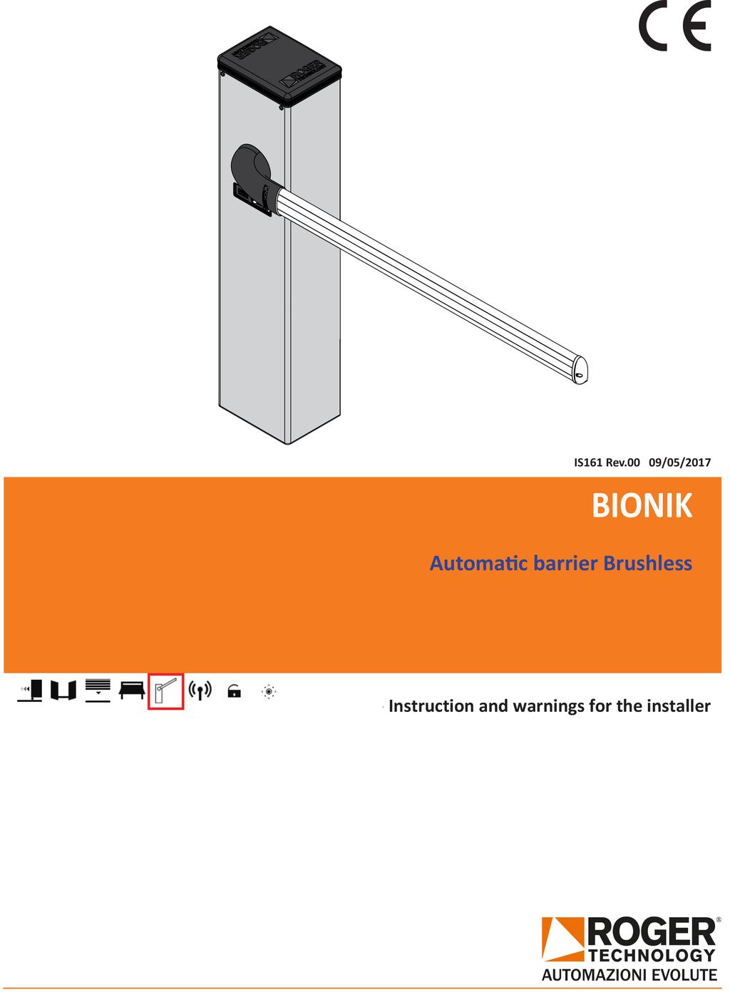
2 16EN 16 1 GENERAL SAFETY PRECAUTIONS Failure to respect the information given in this manual may cause personal injury or damage to the device. This installation manual is intended for qualified personnel only. ROGER TECHNOLOGY cannot be held responsible for any damage or injury due to improper use or any use other the intended usage indicated in this manual. Installation, electrical connections and adjustments must be performed by qualified personnel, in accordance with best practices and in compliance with applicable regulations. Read the instructions carefully before installing the product. Bad installation could be dangerous. Before installing the product, make sure it is in perfect condition: if in doubt, do not use the equipment and contact qualified personnel only. Do not install the product in explosive areas and atmospheres: the presence of inflammable gas or fumes represents a serious safety hazard. Before installing the motorisation device, make all the necessary structural modifications to create safety clearance and to guard or isolate all the crushing, shearing, trapping and general hazardous areas. Make sure the existing structure is up to standard in terms of strength and stability. ROGER TECHNOLOGY is not responsible for failure to observe Good Working Methods when building the frames to be motorised, or for any deformation during use. The safety devices (photocells, safety edges, emergency stops, etc.) must be installed taking into account: applicable laws and directives, Good Working Methods, installation premises, system operating logic and the forces developed by the motorised door or gate. The safety devices must protect against crushing, cutting, trapping and general danger areas of the motorised door or gate. The European standards EN and EN define the minimum safety requirements for the operation of automatic doors and gates. In particular, these standards require the use of force limiting and safety devices (sensing ground plates, photocell barriers, operator detection function etc.) intended to detect persons or objects in the operating area and prevent collisions in all circumstances. Where the safety of the installation is based on an impact force limiting system, it is necessary to verify that the characteristics and performance of the automation system are compliant with the requisites of applicable standards and legislation. The installer is required to measure impact forces and programme the control unit with appropriate speed and torque values to ensure that the door or gate remains within the limits defined by the standards EN and EN ROGER TECHNOLOGY declines all responsibility if component parts not compatible with safe and correct operation are fitted. Display the signs required by law to identify hazardous areas. Each installation must bear a visible indication of the data identifying the motorised door or gate. An omnipolar disconnection switch with a contact opening distance of at least 3mm must be fitted on the mains supply. Make sure that upline from the mains power supply there is a residual current circuit breaker that trips at no more than 0.03A and overcurrent cutout upstream of the electrical system in accordance with best practices and in compliance with applicable regulations. When requested, connect the automation to an effective earthing system that complies with current safety standards. During installation, maintenance and repair operations, cut off the power supply before opening the cover to access the electrical parts. The electronic parts must be handled using earthed antistatic conductive arms. Only use original spare parts for repairing or replacing products. The installer must supply all information concerning the automatic, manual and emergency operation of the motorised door or gate, and must provide the user with the operating instructions. The packaging materials (plastic, polystyrene, etc.) should not be discarded in the environment or left within reach of children, as they are a potential source of danger. Dispose of and recycle the packing components in accordance with the standards in force. These instruction must be kept and forwarded to all possible future user of the system. 2 DECLARATION OF CONFORMITY I the undersigned, as acting legal representative of the manufacturer: Roger Technology - Via Botticelli 8, Bonisiolo di Mogliano V.to (TV) hereby DECLARE that the appliance described hereafter: Description: Automatic barrier Model: BIONIK serie Is conformant with the legal requisites of the following directives: Directive 2006/42/EC (Machinery Directive) and subsequent amendments; Directive 2014/35/EU (Low Voltage Directive) and subsequent amendments; Directive 2011/65/EC (RoHS Directive) and subsequent amendments; Directive 89/106/CEE CPD Directive) and subsequent amendments; and that all the standards and/or technical requirements indicated as follows have been applied: EN EN EN Last two figures of year in which marking was applied 17. Place: Mogliano V.to Date: Signature 3 INTENDED USE The BIONIK automated barrier is specifically conceived for installations in private or public car parks, in residential, commercial or industrial areas or in high traffic zones. This product may only be used for its expressly intended purpose. Any other usage is prohibited. ROGER TECHNOLOGY cannot be held directly or indirectly responsible for any damage resulting from incorrect, inappropriate or unreasonable usage of this product.
3 4 LIMITATIONS USE BIONIK barriers are suitable for VERY HEAVY DUTY operation and may be used with booms up to 4 metres in length. 5 DESCRIPTION OF THE PRODUCT BI/004 BI/004/115 36V DC BIONIK BRUSHLESS barrier for 3 or 4 metre booms, with control unit and on-board native encoder, complete with a fastening base with tie rods and screws and boom fastening flanges. 36V DC BIONIK BRUSHLESS barrier for 3 or 4 metre booms, with control unit and on-board native encoder, complete with a fastening base with tie rods and screws and boom fastening flanges. For 115 V line power supplies. 6 DIMENSIONS All measurements are expressed in mm unless otherwise indicated. EN / PACKAGE CONTENT COMPLETE BIONIK BARRIER CABINET WITH INTEGRATED CONTROL UNIT HEAD COMPLETE WITH DIFFUSER AND BI/BLED FLASHING LAMP UNIT ASSEMBLED BOOM SUPPORT ACCESSORIES - BOLTS AND SCREWS 17
4 8 TECHNICAL CHARACTERISTICS BI/004 BI/004/115 POWER SUPPLY 230 Vac - 50 Hz ±10% 115 Vac - 60 Hz ±10% MOTOR POWER SUPPLY FROM 0 TO 36 Vdc FROM 0 TO 36 Vdc POWER CONSUMPTION FROM 0 TO 15 A FROM 0 TO 15 A POWER MOTOR 220 W 220 W TORQUE FROM 0 TO 200 Nm FROM 0 TO 200 Nm OPEN / CLOSE TIME 90 FROM 3 TO 6 sec FROM 3 TO 6 sec CONTROL SYSTEM ABSOLUTE ENCODER DIGITAL ABSOLUTE ENCODER DIGITAL 18EN 18 USE FREQUENCY CONTINUOUS CONTINUOUS OPERATING CYCLES PER DAY (OPENING/CLOSING - 24 HOURS NO STOP) GRADE OF PROTECTION IP54 IP54 OPERATING TEMPERATURE -20 C +55 C -20 C +55 C CONTROL UNIT (INTEGRATED) 36 Vdc AG/CTRL AG/CTRL ACCESSORIES POWER SUPPLY 24 Vdc 24 Vdc BOOM UP TO 4 METRES UP TO 4 METRES EMERGENCY BATTERY OPTIONAL OPTIONAL RELEASE SYSTEM KEY WITH A STANDARD CYLINDER KEY WITH A STANDARD CYLINDER 9 TYPICAL INSTALLATION 1 Automatic Barrier BIONIK serie 2 Integrated control unit 3 Flashing lights 4 External Photocell 5 Boom with shockproof rubber 6 Strip led Reflective sticker 8 Internal Photocell 9 Fixed end rest for boom complete with a shock-resistant rubber mechanical stop 10 Release system 11 Key or keypad release switch
5 10 REFERENCES AND ACCESSORIES EN Code Description 1 BI/004 Barrier unit cabinet, in carbon steel with anti-corrosion BI/004/115 treatment and painted. 2 Key release with a standard lock RL670 Key release with DIN cylinder (OPTIONAL) 3 Boom support arm rear cover 4 BI/BA3/01 Elliptical boom up to 3 m, in white painted aluminium with slot cover profiles and shock-resistant rubber. BI/BA4/01 Elliptical boom up to 4 m, in white painted aluminium with slot cover profiles and shock-resistant rubber. 5 Boom support arm in die-cast aluminium. 6 Boom support arm front cover. Head in die-cast aluminium with anti-corrosion treatment 7 and painted, complete with diffuser in transpa- rent polycarbonate and BI/BLED led lights. 8 AG/CTRL Controller unit 9 Gate open/close mechanical stop 10 Steel spring fastening linkage lever 11 Gear motor complete with brushless motor and absolute encoder 12 Corrosion-proof, painted steel inspection hatch. 13 KT240 Galvanised base plate for barrier fastening. 14 BI/ALED4C 4 m LED strip. 15 AG/SP61/01 Blue Ø61 spring (for booms and accessories, see chap. 12). 16 AG/SP72/01 Red Ø72 spring (for booms and accessories, see chap. 12) Code Description 17 KT231 Fixed end rest fastening plate. 18 AG/BAFS/01 Fixed end rest, non-adjustable, with rubber buffer. 19 AG/BAFS/03 Fixed end rest with rubber, non-adjustable, with holes for a latch chain and rubber buffer. 20 AG/BAFS/02 Fixed end rest with rubber, adjustable, telescopic with rubber buffer. 21 AG/BAFS/04 Fixed end rest with rubber, adjustable, telescopic with holes for a latch chain and rubber buffer. 22 AG/BAFS/05 Fixed end rest with rubber, adjustable, telescopic with rubber buffer and integrated magnet. 23 AG/BAMS/01 Hinged end rest for booms. 24 AG/BAMS/01/EXT Extension for hinged end rest 25 AG/BARK/02 Drop skirt in painted aluminium. L = 2 m. 26 BI/BAJ/02 Joint with 90 pivot point with lower tie-rod 27 BI/BAJ/03 Joint with 90 pivot point with upper tie-rod 28 BI/BAT/KIT Emergency battery kit complete with battery charger and wiring (optional). 29 BI/BCHP Battery charge board complete with wiring (optional) 30 KT239 DIN bar 31 AG/BASB40 Package of 40 refractive adhesive strips for the boom. 32 RS/GR1/100 Lithium grease (EP LITIO). 19


6 11 INSTALLATION 11.1 Preliminary checks Check that the material received is in good condition and suitable for the application. Check that the operating limits of the product are not exceeded. Check that the site chosen for installation meets the overall space requirements of the product and that there are no obstacles hindering open or close manoeuvres. Check the concrete base for the barrier installation. The base must be cast in accordance with proper working practices, perfectly level and clean Installing base plate 20EN 20 The illustrations herein are indicative only. The space necessary for fastening the automation system and the accessories may vary depending on the overall dimensions of the installation. The installer is responsible for determining the most suitable solution. Excavate a foundation pit measuring 1m x 1m x 0.4 m and fill with concrete reinforced with steel mesh. Fasten the 4 anchor ties to the plate (fig. 1). N.B.: the bottom nut must be tightened to the end of the thread on the screw so that the length Z is at least 40 mm. Sink the base plate with the anchors in the centre of the foundation pit, so that the surface is flush with the concrete and perfectly level. The corrugated cable conduits must protrude by a few centimetres from the centre of the plate. PAY ATTENTION to the installation direction of the plate. See the detailed view in fig. 2. The inspection side must be accessible from inside the home / shop / business. Installation on existing surfaces. Place the base plate on the surface and trace the positions of the fastener points. Drill the surface and fit 4 expansion anchor bolts (purchased separately) Installing the barrier N.B.: the barrier is configured by default for installation on the right hand side (viewed from the inspection hatch). Undo and remove the washers and nuts from the anchors on the base plate (fig. 3). Open the inspection hatch, turning the key clockwise 90 (fig. 4) and remove it. Place the cabinet on the plate. The anchors on the base plate must fit through the four slots. Fit the washers and nuts removed previously. Move the cabinet as necessary in the slots to adjust the position of the barrier correctly. Tighten the nuts securely (fig. 6). 1 KT Z=>40 mm Lato sportello di ispezione Inspection hatch side 53 4xØ12,
7 EN 11.4 Selecting direction of aperture BIONIK barriers are configured by default for installation on the right hand side (seen from the inspection hatch side). For left hand installations: Unlock the barrier (see chapter 21). Turn the linkage lever as shown in figure. Move the mechanical stop. Lock the barrier (see chapter 21). LEFT RIGHT 7 LEFT-HAND INSTALLAZIONE SIDE INSTALLATION A SINISTRA INSTALLAZIONE RIGHT-HAND SIDE INSTALLATION A DESTRA 21
8 11.5 Support and boom installation 1. Unlock the barrier (see chapter 21). 2. Based on the opening direction of the barrier (fig. 7), turn the linkage lever until reaching the stop on the mechanical limit switch (fig. 7), in the position in which it is possible to install the boom horizontally. 3. Lock the barrier. 4. Open the boom support cover [A] by unscrewing the self-tapping screws TCC 4.2x19 [B]. 5. Loosen the screws [E1] and insert the boom support [C] on the drive shaft [D] making sure that there is a maximum distance of 1 mm between the support and the barrier cabinet, as shown in the detailed view. 6. Fasten the support with the TCEI M8x35 screws [E1], [E2] and [E3] tightening them securely. 7. Fasten the rear cover with the provided self-tapping screws [F] TCC 4.2x Unscrew the screws [G] TCC 4.2x13 and remove the cap [H]. 9. Unscrew the screws [I] TCC 2.9x19. Remove the support [L], shock-resistant rubber [M] and the profile [N] at least 200 mm. 10. Insert the boom [O] in the support [C] and fasten it with the provided screws TCEI M8x20 [P] (complete with washers). 11. Reposition the profile [N], the shock-resistant rubber [M] and the plastic support [L] and fasten them with the screws [I] TCC 2.9x Fasten the cap [H] with the screws [G] TCC 4.2x Fasten the plastic support cover [A] with the self-tapping screws TCC 4.2x19 [B]. 22EN 22 A E1 C F C C E2 P E3 P 1 mm C D E3 B E3 O N 200 L M I H G 8
9 12 INSTALLING AND ADJUSTING THE SPRING Select the desired opening direction as indicated in paragraph Unlock the barrier (see chapter 21) and move the boom into the completely open vertical position. Select the most suitable spring (see tables in paragraph 12.1). The springs are colour coded for identification. The coloured part of the spring must always be at the top.: blue - Ø61 springs (AG/SP61/01); red - Ø72 springs (AG/SP72/01). Unscrew the upper screw TE M14x60 of the spring (viewed from the top coloured side). Unscrew the screw TE M14x45 from the linkage lever and fasten the spring with the same screw (fig. 9): - For barriers with left-side opening, use the SX1 or SX2 holes. - For barriers with right-side opening, use the DX2 or DX3 holes. Fasten the springs to the fixed structure (fig. 9), on the steel cross bar of the barrier, using the screws TE M14x60 included in the package. Lubricate the pivot points with lithium based grease (EP LITIO) (fig. 10). Available upon request, article RS/GR1/100: 100 g can of lithium grease. To adjust the spring tension, loosen the nuts [A] as indicated in fig Then turn the spring [B] clockwise to reduce the tension or anticlockwise to increase tension (fig. 11). Lift the boom manually to an angle of 45 and let go. If the boom rises, reduce the spring tension. If the boom drops, increase the spring tension. Once the spring tension is correct, tighten the nuts securely [A]. EN 9 TE M14x60 1 SX LT TE M14x45 2 DX RT TE M14x Grasso Grease A B B A 23
10 12.1 Spring selection The booms are understood as complete with shock-resistant rubber and LED strips. BI/BA3/01 BI/BA4/01 (with boom up to 4 m) Blu/Blue AG/SP61/01 EN (with boom up to 3 m) The adjustable fixed end rest with integrated magnet AG/BAFS/05 must be used. Rosso/Red AG/SP72/01 Configuration only possible if the drop skirt is installed as close as possible to the cabinet. The fixed end rest must be used. The adjustable fixed end rest with integrated magnet AG/BAFS/05 must be used. 24 1m 1m The adjustable fixed end rest with integrated magnet AG/BAFS/05 must be used.
11 13 ADJUSTING THE MECHANICAL STOP The figure shows the mechanical stop on a barrier installed on the left hand side. For barriers installed on the right, perform the mirror images of the procedures illustrated. Unlock the barrier (see chapter 21). Set the completely open and completely closed positions by adjusting the relative mechanical stops. Lock the barrier (see chapter 21). CHIUSA CLOSE APERTA OPEN CONNECTING PHOTOCELLS F4ES type photocells may be installed on both sides of the barrier at two different heights: (50 cm or 100 cm). 1. Disconnect the mains power (if applicable). 2. Switch the control unit switch to the OFF position (fig. 15). 3. Open the photocells, rest the base on the cabinet and use it as a drilling template. 4. Drill the barrier cabinet as shown in figure 13 and fasten the base of the photocells. 5. Route the connector cables upwards, taking care not to interfere with the movements of the automation system and through the cable conduit indicated in figure Connect the photocells to the terminals COM-FT1/FT2 as indicated in the control unit installation manual. 7. Refer to the control unit manual for the photocell settings. 8. Set the switch to the ON position. 9. Reconnect to mains power. EN TX 990 RX 490 RX TX Ø15 4xØ3,25 25
12 15 ELECTRICAL CONNECTIONS 26EN 26 All electrical connections must be made with the unit disconnected from mains power and, if applicable, battery power. See controller manual for instructions on making connections and programming. Before connecting to electrical power, ensure that the mains power specifications on the identification plate match the mains power supply used. A switch or an omnipolar cut-off switch with a contact opening of at least 3 mm must be installed on the mains power line. Ensure that an adequate residual current circuit breaker and a suitable overcurrent cut-out are installed ahead of the electrical installation. Use a 3x2.5 mm 2 double insulated cable for the mains power line. Feed the cable on the left hand side of the barrier through the rubber cable grommet on the left hand side of the controller casing and connect it to the terminals L (brown), N (blue) and (yellow/green) inside the automation unit. Fasten the power cable with the cable grips included. At least 50 mm of the connector cable conduit must protrude from the holes in the base plate and into the automation unit. 16 INSTALLING THE BATTERY KIT (OPTIONAL) 1. Disconnect the mains power. 2. Unscrew the screws and remove the head [A] (if applicable). 3. Lift the cable grommet [B] and disconnect the connector [C]. 4. Open the transparent control unit cover [D]. 5. Switch the control unit switch to the OFF position [E]. 6. Lift the control unit and insert the batteries in their housing [F]. 7. Connect the red, black and blue wires to the batteries (see detailed view) 8. Connect the batteries to the +BATTERY terminal (red wire) and -BATTERY terminal (black wire). 9. Insert the battery charge board BI/BCHP in the plug-in connector [G]. 10. Reposition the control unit. 11. Switch the control unit switch to the ON position [E]. 12. Reposition the transparent control unit cover [D]. 13. Reconnect the connector [C] and close the cable grommet [B]. 14. Close the head [A] and tighten the front screws. 15. Reconnect the mains power. 16 A B C D BATTERY (+) BATTERY (-) SEC2 G E OFF BATTERY C N L RED BLACK F ROSSO/RED (+) NERO/BLACK (-) BLU/BLUE G
13 17 INSTALLING THE BI/BLED LED FLASHING LIGHT 1. The BI/BLED flashing lamp unit is factory supplied already pre-installed in the head [A], packaged separately inside the BIONIK package. 2. Insert the connector [B] in the LIGHT terminal of the control unit. 3. Refer to the control unit manual for the flashing lamp unit settings. 4. Fasten the cable grommet [C], making sure it is positioned correctly. 5. Position the head [A] on the barrier. 6. Tighten the fastening screws. In case of replacement: 1. Disconnect the mains and battery power supplies (if applicable). 2. Unscrew the screws that fasten the head [A] to the barrier. 3. Lift the cable grommet [C]. 4. Disconnect the connector [B]. 5. Remove and overturn the head [A]. 6. Remove the BI/BLED flashing lamp unit [D] from the diffuser. 7. Insert the new LED circuit in the diffuser, paying attention to the installation direction (fig. 18). 8. Insert the connector [B] in the LIGHT terminal of the control unit. 9. Refer to the control unit manual for the flashing lamp unit settings. 10. Fasten the cable grommet [C], making sure it is positioned correctly. 11. Reposition the head [A] on the barrier. 12. Tighten the fastening screws. 13. Reconnect the mains and battery power supplies (if applicable). EN 17 A A C B LED LIGHT B 18 A D D 27
14 che 18 MAINTENANCE possano danneggiare il cavo di alimentazione. 19 DISPOSAL 28EN 28 N.B.: Only use original spare parts when repairing or replacing products. The installer must provide the user with complete instruction for using the motorised door or gate in automatic, manual and emergency modes, and must hand the operating instructions to the user of the installation upon completion. The installer must compile the maintenance log book, in which all scheduled and unscheduled maintenance operations performed must be indicated. The installation must be subject to regular maintenance. We recommend servicing at least once every 6 months. Disconnect from mains electricity and from battery power (if applicable) to avoid the risk of accident or injury. Check the tightness of all the fastener screws and nuts. Clean the photocell lenses with a cloth moistened slightly with water. Do not use solvents or other chemical products, as these may damage the electronic components. Clean and lubricate the pivot points with lithium based grease (EP LITIO). Check the electrical connections. Check that the manual lock release system works. Check that the boom is balanced correctly as indicated in chapter 12. Check that there are now plants within the radius of action of the boom which could interfere with the photocells or with the movements of the boom itself. Reconnect to mains power. Check that the safety devices and all the control functions work correctly. Check that the obstacle detection function works correctly. Check that there is no risk of the boom accidentally lifting persons or objects. Check that the force limiting function prevent potentially dangerous situations in compliance with the standard EN RELEASE AND LOCK PROCEDURE FIG. 1 This product may only be uninstalled by qualified technical personnel, following suitable procedures for removing the product correctly and safely. This product consists of numerous different materials. Some of these materials may be recycled, while others must be disposed of correctly at the specific recycling or waste management facilities indicated by local legislation applicable for this category of product. Do not dispose of this product as domestic refuse. Observe local legislation for differentiated refuse collection, or hand the product over to the vendor when purchasing an equivalent new product. Local legislation may envisage severe fines for the incorrect disposal of this product. Warning! some parts of this product may contain substances that are harmful to the environment or dangerous and which may cause damage to the environment or health risks if disposed of incorrectly. 20 ADDITIONAL INFORMATION AND CONTACT ROGER TECHNOLOGY is the exclusive proprietor holder of all rights regarding this publication. ROGER TECHNOLOGY reserves the right to implement any modifications without prior notification. Copying, scanning or any alterations to this document are prohibited without express prior authorised from by ROGER TECHNOLOGY. ROGER TECHNOLOGY CUSTOMER SERVICE: business hours: Monday to Friday 08:00 to 12:00-13:30 to 17:30 Telephone no: support@rogertechnology.it Skype: service_rogertechnology Unlock the barrier in the event of a power outage or before performing scheduled maintenance or repairs. The unlock procedure must be performed with the boom in the closed position. Ensure that there are no persons, objects or animals within the operating radius of the barrier when unlocking. RELEASE AND MANUAL OPERATION Open the lock cover as indicated in step 1. Insert the key included into the lock and turn clockwise by 90, as indicated in step 2. Open the release cover completely (3). Move the boom manually. RESTORING AUTOMATIC OPERATION To relock the barrier, close the release cover by turning the key 90 clockwise, paying attention to your fingers. With the door closed, turn the key 90 anticlockwise. Remove the key and close the lock cover. 3 FIG. 2
EC MACHINE DIRECTIVE COMPLIANCE DECLARATION
 EC MACHINE DIRECTIVE COMPLIANCE DECLARATION (DIRECTIVE 89/392 EEC, APPENDIX II, PART B) Manufacturer: FAAC S.p.A. Address: Via Benini, 1 40069 - Zola Predosa BOLOGNA - ITALY Hereby declares that: the 770
EC MACHINE DIRECTIVE COMPLIANCE DECLARATION
 770 EC MACHINE DIRECTIVE COMPLIANCE DECLARATION (DIRECTIVE 89/392 EEC, APPENDIX II, PART B) Manufacturer: FAAC S.p.A. Address: Via Benini, 1 40069 - Zola Predosa BOLOGNA - ITALY Hereby declares that: the
Ditec PWR25H/35H Automation for hinged gates
 Ditec PWR25H/35H Automation for hinged gates (translation of the original instructions) www.entrematic.com IP2250EN Technical Manual Contents Subject Page 1. General safety precautions 27 2. Declaration
Ditec LUXO Swing gates automation (Original instruction)
") Ditec LUXO Swing gates automation (Original instruction) IP2128EN Technical manual www.ditecentrematic.com Index Subject Page 1. General safety precautions 21 2. Declaration of incorporation of partly
Ditec LUXO Swing gates automation (Original instruction) IP2128EN Technical manual www.ditecentrematic.com Index Subject Page 1. General safety precautions 21 2. Declaration of incorporation of partly
THE NEW DIGITAL REVOLUTION IN THE AUTOMATION SECTOR
 THE NEW DIGITAL REVOLUTION IN THE AUTOMATION SECTOR CATALOGUE NOVEMBER 2017 THE BRUSHLESS MOTOR The Roger Technology Brushless motor is a digital three phase motor. The word Brushless means a motor without
IP2160 EN. Ditec NEOS Sliding Gates. Technical Manual. (Original instructions)
") Ditec NEOS Sliding Gates (Original instructions) IP2160 EN Technical Manual www.ditecentrematic.com Index Subject Page 1. General safety precautions 4 2. Declaration of incorporation of partly completed
Ditec NEOS Sliding Gates (Original instructions) IP2160 EN Technical Manual www.ditecentrematic.com Index Subject Page 1. General safety precautions 4 2. Declaration of incorporation of partly completed
Ditec QIK80EH Electromechanical barrier. IP2085EN Technical Manual. (Original instructions)
") Ditec QIK80EH Electromechanical barrier (Original instructions) IP2085EN Technical Manual www.ditecentrematic.com 2 Index Subject Page 1. General safety precautions 4 2. EC Declaration of Conformity 5
Ditec QIK80EH Electromechanical barrier (Original instructions) IP2085EN Technical Manual www.ditecentrematic.com 2 Index Subject Page 1. General safety precautions 4 2. EC Declaration of Conformity 5
Ditec QIK4E-7EH-7YEH Electromechanical barrier (Original instructions)
") Ditec QIK4E-7EH-7YEH Electromechanical barrier (Original instructions) IP1861EN Technical Manual www.ditecentrematic.com 24 Index Key Subject 1. General safety precautions 26 2. EC Declaration of Conformity
Ditec QIK4E-7EH-7YEH Electromechanical barrier (Original instructions) IP1861EN Technical Manual www.ditecentrematic.com 24 Index Key Subject 1. General safety precautions 26 2. EC Declaration of Conformity
BULL 424 ESA BULL 624 ESA
 L8542677 01/2012 rev 1 BULL 424 ESA BULL 624 ESA UNIONE NAZIONALE COSTRUTTORI AUTOMATISMI PER CANCELLI, PORTE SERRANDE ED AFFINI 1 140 260 92 83 330 330 210 326 2 X BULL.P3 34 mm = = 3 3 4 P P D 102 mm
Automatic concealed bollards 275 H600 and 275 H800 with pit
 Automatic concealed bollards 275 H600 and 275 H800 with pit Technical installation manual CE Declaration of conformity Warnings for the installer Bollard technical data Preparing and installing the bollard
EC DECLARATION OF CONFORMITY FOR MACHINES (DIRECTIVE 98/37/EC) WARNINGS FOR THE INSTALLER
 WARNINGS FOR THE INSTALLER") EC DECLARATION OF CONFORMITY FOR MACHINES (DIRECTIVE 98/37/EC) Manufacturer: Address: Declares that: FAAC S.p.A. Via Benini, 1-40069 Zola Predosa BOLOGNA - ITALY 740-24V mod. operator is built to be integrated
EC DECLARATION OF CONFORMITY FOR MACHINES (DIRECTIVE 98/37/EC) Manufacturer: Address: Declares that: FAAC S.p.A. Via Benini, 1-40069 Zola Predosa BOLOGNA - ITALY 740-24V mod. operator is built to be integrated
MEKO OPENER FOR RACK-DRIVEN SLIDING MOTOR
 Installation Manual MEKO OPENER FOR RACK-DRIVEN SLIDING MOTOR 02_2016 1. WARNINGS AND GENERAL SAFETY INSTUCTIONS This manual contains important safety information. An incorrect installation or an improper
Ditec BOX Balanced up and over doors
 Ditec BOX Balanced up and over doors (original instructions) IP1529EN Technical Manual www.ditecentrematic.com All the rights concerning this material are the exclusive property of Entrematic Group AB.
Installation manual. English. mystrike OPENER FOR RACK-DRIVEN SLIDING MOTOR
 Installation manual English mystrike OPENER FOR RACK-DRIVEN SLIDING MOTOR 1. WARNINGS AND GENERAL SAFETY INSTRUCTIONS This manual contains important safety information. An incorrect installation or an
INDEX CE DECLARATION OF CONFORMITY FOR MACHINES... 2 WARNINGS FOR THE INSTALLER DESCRIPTION AND TECHNICAL SPECIFICATIONS...
 INDEX CE DECLARATION OF CONFORMITY FOR MACHINES... 2 WARNINGS FOR THE INSTALLER... 2 1. DESCRIPTION AND TECHNICAL SPECIFICATIONS... 3 1.1 MAXIMUM USE CURVE... 4 2 ELECTRIC PREPARATIONS (standard system)...
Ditec CUBIC Swing gates automation
 Ditec CUBIC Swing gates automation (Original instructions) IP1812EN Technical Manual www.entrematic.com Index Subject Page 1. General safety precautions 21 General safety precautions for the user 22 2.
Installation manual ASTER AUTOMATION FOR SWING GATES 11_16
 Installation manual ASTER AUTOMATION FOR SWING GATES 11_16 Contents 1. GENERAL SAFETY PRECAUTIONS... page 01 2. INTENDED USE AND APPLICATION... page 01 2.1 Kit contents... page 01 2.2 Technical features...
Typical Installation Schematic
 The 760 Gate Automation System The FAAC 760 automation system consists of a monoblock hydraulic unit and foundation box assembly. The system is designed for underground installation, and will not alter
Contents. EC DECLARATION OF CONFORMITY FOR MACHINES... p. 10. WARNINGS FOR THE INSTALLER... p. 10
 Contents EC DECLARATION OF CONFORMITY FOR MACHINES... p. 10 WARNINGS FOR THE INSTALLER... p. 10 1. DESCRIPTION AND TECHNICAL SPECIFICATIONS... p. 11 1.1. DIMENSIONS... p. 11 2. ELECTRIC DEVICES (standard
INSTALLATION MANUAL FOR SWING SHUTTERS KAF212. FACE S.r.l. Viale delle Industrie, Dosson di Casier Treviso Italy
 INSTALLATION MANUAL FOR SWING SHUTTERS KAF212 FACE S.r.l. Viale delle Industrie, 74 31030 Dosson di Casier Treviso Italy INDEX Subject Page 1. General safety instruction 2 1.1 EC marking and European directives
MOUNTING AND CONNECTING INSTRUCTIONS 1. GATE ARRANGEMENT ENGLISH
 SATURN SATURN is a motor reducer designed for the automation of sliding gates with grease lubrication of the gear in the 600 version; in oil bath in the 1000 and 2000 versions. The irreversibility of the
BULL 5M - BULL 5M.S BULL 8M - BULL 8 M.S BULL 8 OM - BULL 8 OM.S
 L8542676 04/2012 rev. 2 BULL 5M - BULL 5M.S BULL 8M - BULL 8 M.S BULL 8 OM - BULL 8 OM.S UNIONE NAZIONALE COSTRUTTORI AUTOMATISMI PER CANCELLI, PORTE SERRANDE ED AFFINI 1 140 260 100 91 330 330 210 326
Ditec PWR50H/HV/HR Automation for swing gates
 Ditec PWR50H/HV/HR Automation for swing gates (translation of the original instructions) IP2253EN Technical Manual www.entrematic.com Contents Subject Page 1. General safety precautions 23 2. Declaration
Installation Manual. Swing Gate System. Leading the way...
 Installation Manual 402 Swing Gate System Leading the way... Contents EC DECLARATION OF CONFORMITY FOR MACHINES... p. 2 WARNINGS FOR THE INSTALLER... p. 2 1. DESCRIPTION AND TECHNICAL SPECIFICATIONS...
E R A I GATE AUTOMATION DIVISION
 S E R A I GATE AUTOMATION DIVISION INSTALLATION MANUAL MC/5C - 03.5C UNDERGROUND MOTOR 230 Vac FOR WING GATES UP TO 3,00m AND 300 Kg EACH WING + FOUNDATION BOX IN HOT-GALVANISED STEEL Thank you for choosing
EC DECLARATION OF CONFORMITY FOR MACHINES (DIRECTIVE 98/37/EC)
") EC DECLARATION OF CONFORMITY FOR MACHINES (DIRECTIVE 98/37/EC) Manufacturer: Address: Declares that: FAAC S.p.A. Via Benini, 1-40069 Zola Predosa BOLOGNA - ITALY The operator mod. 844 R Reversible is built
EC DECLARATION OF CONFORMITY FOR MACHINES (DIRECTIVE 98/37/EC) Manufacturer: Address: Declares that: FAAC S.p.A. Via Benini, 1-40069 Zola Predosa BOLOGNA - ITALY The operator mod. 844 R Reversible is built
FORCE SPD 800/1500/2000
 English AUTOMATION SYSTEMS FOR SLIDING GATES Operating and installation instructions FORCE SPD 800/1500/2000 v1.0 Rev 11/2012 INDEX 1) General Safety Regulations... pág. 01 2) Description... pág. 02 3)
AUTOMATION SYSTEM FOR SWING GATES FROG SERIES INSTALLATION MANUAL SUPERFROG
 AUTOMATION SYSTEM FOR SWING GATES FROG SERIES INSTALLATION MANUAL SUPERFROG IMPORTANT SAFETY INSTRUCTIONS FOR INSTALLATION CAUTION: IMPROPER INSTALLATION MAY CAUSE SERIOUS DAMAGE, FOLLOW ALL INSTALLATION
Automation Swing Gate Opener
 Automation Swing Gate Opener Operating and installation instructions SP EIFFEL 400 V1.0 Rev 08/01 CONTENTS 0) GENERAL SAFETY REGULATIONS...Page 0 1) DESCRIPTION...Page 03 ) TECHNICAL SPECIFICATIONS 3)
EC DECLARATION OF CONFORMITY FOR MACHINES WARNINGS FOR THE INSTALLER
 EC DECLARATION OF CONFORMITY FOR MACHINES (DIRECTIVE 2006/42/EC) Manufacturer: Address: Declares that: FAAC S.p.A. Via Benini, 1-40069 Zola Predosa BOLOGNA - ITALY 740 / 741 mod. operator is built to be
WEL. Manuale di installazione e manutenzione per automazioni per porte battenti. Installation and maintenance. for swing doors.
 WEL IP1891 - rev. 2007-04-20 I GB F D E P Manuale di installazione e manutenzione per automazioni per porte battenti. Installation and maintenance manual for automations for swing doors. Manuel d installation
INSTRUCTIONS FOR INSTALLATION
 HYDRAULIC OPERATOR MODO 110-110/L FOR SINGLE- OR DOUBLE-WING SWING GATES INSTRUCTIONS FOR INSTALLATION GENERAL WARNINGS These warnings constitute an integral and essential part of the product and must
IRREVERSIBLE OPERATOR FOR SWING GATES AND DOORS
 VH IRREVERSIBLE OPERATOR FOR SWING GATES AND DOORS WARNING!! Before installing, thoroughly read this manual that is an integral part of the pack Our products if installed by qualified personnel capable
CE DECLARATION OF MACHINE CONFORMITY
 CE DECLARATION OF MACHINE CONFORMITY (DIRECTIVE 2006/42/EC) Manufacturer : Address: Declares that: FAAC S.p.A. Via Calari, 10-40069 Zola Predosa BOLOGNA - ITALY Operator mod. 541 3ph is built to be incorporated
L /2013 rev 0 BISON 35 OTI UNIONE NAZIONALE COSTRUTTORI AUTOMATISMI PER CANCELLI, PORTE SERRANDE ED AFFINI
 L8543019 04/2013 rev 0 BISON 35 OTI UNIONE NAZIONALE COSTRUTTORI AUTOMATISMI PER CANCELLI, PORTE SERRANDE ED AFFINI 1 458 250 A F 645 477 B 195 470 270 2 C 13 ±5 156 70 2 3 4 D2 R D2 I D1 T 5 W D H G R
Ditec DOD Industrial sectional door automations
 Ditec DOD Industrial sectional door automations (Original instructions) IP1733EN Technical manual www.ditecentrematic.com Index Subject Page 1. General safety precautions 33 2. Declaration of incorporation
Ditec VALOR Sliding doors automation (Original instructions)
") Ditec VALOR Sliding doors automation (Original instructions) IP1950 EN Technical manual www.entrematic.com Index Subject Page 1. General safety precautions 3 2. Declaration of incorporation of partly completed
Ditec VALOR Sliding doors automation (Original instructions) IP1950 EN Technical manual www.entrematic.com Index Subject Page 1. General safety precautions 3 2. Declaration of incorporation of partly completed
FITTING AND CONNECTION INSTRUCTIONS
 LEPUS is an oil-bathed motor-reducer created for sliding gates automation. The motor-reducer irreversibility allows a perfect and safe gate closing avoiding the setup of an electrolock and in case of power
DOCUMENT TYPE = FITTING INSTRUCTIONS ORIGINAL LANGUAGE = ENGLISH. Maximum door weight = 40kg per leaf total system 80kg
 Evolve SIM Kit DOCUMENT TYPE = FITTING INSTRUCTIONS ORIGINAL LANGUAGE = ENGLISH 80kg Maximum door weight = 40kg per leaf total system 80kg Maximum door width 2 x 2mtr Track = 675-1058mm (Up to 2035 mm
IMPORTANT NOTICE FOR THE INSTALLER
 EC MACHINE DIRECTIVE COMPLIANCE DECLARATION (DIRECTIVE 89/392 EEC, APPENDIX II, PART B) Manufacturer: FAAC S.p.A. Address: Via Benini, 1 40069 - Zola Predosa BOLOGNA - ITALY Hereby declares that: the 6
SLIDE & OL USER'S AND INSTALLER'S MANUAL V1.0 REV. 06/2017
 SLIDE & OL USER'S AND INSTALLER'S MANUAL V1.0 REV. 06/2017 00. CONTT 01. SAFETY INSTRUCTIONS INDEX 01. SAFETY INSTRUCTIONS STANDARDS TO FOLLOW 02. OPERATOR TECHNICAL SPECIFICATIONS DESCRIPTION DIMSIONS
UNDERGROUND OPERATOR FOR SWINGING GATES. WARNING!! Before installing, thoroughly read this manual that is an integral part of the pack
 UNDERGROUND OPERATOR FOR SWINGING GATES COMPAS 2 WARNING!! Before installing, thoroughly read this manual that is an integral part of the pack Our products if installed by qualified personnel capable to
EC DECLARATION OF CONFORMITY
 EC DECLARATION OF CONFORMITY Manufacturer : Address: Declares that: FAAC S.p.A. Via Benini, 1-40069 Zola Predosa BOLOGNA - ITALY 844 T control board, conforms to the essential safety requirements of the
BISON 20 OM BISON 25 OTI
 L8542939 11/2011 rev 0 BISON 20 OM BISON 25 OTI UNIONE NAZIONALE COSTRUTTORI AUTOMATISMI PER CANCELLI, PORTE SERRANDE ED AFFINI 2 x 1,5 GND 13 8 7 5 RG 58 4 3 4 x 0,35 6 1 2 4 3 x 1,5 min 230V 2 x 0,35
L /2012 rev 0 BISON 45 OTI UNIONE NAZIONALE COSTRUTTORI AUTOMATISMI PER CANCELLI, PORTE SERRANDE ED AFFINI
 L8542965 03/2012 rev 0 BISON 45 OTI UNIONE NAZIONALE COSTRUTTORI AUTOMATISMI PER CANCELLI, PORTE SERRANDE ED AFFINI 1 470 327 F A 500 825 B 243.5 2 C 445 210 15 ±5 205 92 50 2 3 4 I D2 D2 D1 5 T 6 D A
L /2012 rev 0 BISON 30 OTI UNIONE NAZIONALE COSTRUTTORI AUTOMATISMI PER CANCELLI, PORTE SERRANDE ED AFFINI
 L8542968 07/2012 rev 0 BISON 30 OTI UNIONE NAZIONALE COSTRUTTORI AUTOMATISMI PER CANCELLI, PORTE SERRANDE ED AFFINI 1 458 250 A F 645 477 B 195 470 270 2 C 13 ±5 156 70 2 3 4 D2 R D2 I D1 T 5 W D H G R
INSTALLER AND USER S MANUAL. v4.0 REV. 01/2019
 MBM6 -BARRIER INSTALLER AND USER S MANUAL v4.0 REV. 01/2019 00. CONTT INDEX 01. SAFETY INSTRUCTIONS STANDARDS TO FOLLOW 01. SAFETY INSTRUCTIONS STANDARDS TO FOLLOW 02. PACKAGE INSIDE PACKAGE 03. OPERATOR
GROUND GROUND - ( ) Interrati elettromeccanici ISTRUZIONI PER L INSTALLAZIONE. Electromechanical underground INSTRUCTIONS FOR INSTALLATIONS
 Interrati elettromeccanici ISTRUZIONI PER L INSTALLAZIONE. Electromechanical underground INSTRUCTIONS FOR INSTALLATIONS") GROUND GROUND - (610-624) Interrati elettromeccanici ISTRUZIONI PER L INSTALLAZIONE Electromechanical underground INSTRUCTIONS FOR INSTALLATIONS I UK F E D P NL GR 2 GROUND 1a 6 3 4 7 Ø 5 x4 3 9 1 8 1
GROUND GROUND - (610-624) Interrati elettromeccanici ISTRUZIONI PER L INSTALLAZIONE Electromechanical underground INSTRUCTIONS FOR INSTALLATIONS I UK F E D P NL GR 2 GROUND 1a 6 3 4 7 Ø 5 x4 3 9 1 8 1
SARGON S - M - L. All rights reserved INSTALLATION MANUAL
 INSTALLATION MANUAL Our compliments for your excellent choice. SARGON LINE S (300mm) M (400mm) and L (600mm) electro-mechanical gear motor has been produced for reliability and high quality. This Manual
Control panel installation manual for 230 V~ automation with one or two motors D5 S5 JT RF ON TC RP TR R1 OM J7. Electric lock. Flashing light.
 FUSE Ditec LOGIC M Control panel installation manual for 230 V~ automation with one or two motors IP1854EN LOGICM F2 FUSE JR4 JR10 SO D5 S5 JT NIO CT 1 2 3 4 5 RF ON AUX AUX F1 POWER SA IN 11 12 TM JR6
AC 100. Operating instructions Pneumatic Crimper AC 100. Date of issue: 05/2010. Keep for future use!
 Operating instructions Pneumatic Crimper AC 100 Date of issue: 05/2010 Keep for future use! SAFETY SAFETY Basic information The basic prerequisite for ensuring safe use and continuous operation of the
Ditec CROSS18-19 Sliding gates automation. IP1984 EN Technical Manual. (original instructions)
") Ditec CROSS18-19 Sliding gates automation (original instructions) IP1984 EN Technical Manual www.ditecentrematic.com 2 Index Subject Page 1. General safety precautions 4 2. Declaration of incorporation
Ditec CROSS18-19 Sliding gates automation (original instructions) IP1984 EN Technical Manual www.ditecentrematic.com 2 Index Subject Page 1. General safety precautions 4 2. Declaration of incorporation
VERG 24V BARRIER. English
 VERG 24V BARRIER General features VERG 24V is an electro-mechanical barrier (2, 3, 4, 5 m) recommended for the automation of access points which require a high opening/closing speed (parking lots, motorways,
ECO PLUS RAPID DOOR USER S AND INSTALLER S MANUAL
 ECO PLUS RAPID DOOR USER S AND INSTALLER S MANUAL v1.0 REV. 02/2018 00. CONTT 01. SAFETY INSTRUCTIONS INDEX 01. SAFETY INSTRUTIONS STANDARDS TO FOLLOW 02. THE AUTOMATISM COMPONTS TECHNICAL SPECIFICATIONS
INSTALLATION MANUAL ENGLISH ALPHA 200 ALPHA 330. L C (stroke) 960 mm 1160 mm
 960 mm 1160 mm") INSTLLTION MNUL The LPH is provided with a mechanical locking system that grants the operator locking in the opened and closed position avoiding any needs for electric locks and/or magnetic locks. The
INSTLLTION MNUL The LPH is provided with a mechanical locking system that grants the operator locking in the opened and closed position avoiding any needs for electric locks and/or magnetic locks. The
CICLÓN ATTUATORE ELETTROMECCANICO IRREVERSIBILE A BRACCIO SNODATO PER CANCELLI A BATTENTE
 by IL n. 366 EDIZ. 28/03/2012 CICLÓN I GB F E P D ATTUATORE ELETTROMECCANICO IRREVERSIBILE A BRACCIO SNODATO PER CANCELLI A BATTENTE IRREVERSIBLE ELECTROMECHANICAL PIVOTING ARM ACTUATOR FOR SWING GATES
Operating instructions Solenoid interlock TKM/TKF. 1. About this document. Content
 1. About this document Operating instructions.............pages 1 to 6 Original 1.1 Function This operating instructions manual provides all the information you need for the mounting, set-up and commissioning
Mod: KLD6-12/35XLAS-N
 12/2011 Mod: KLD6-12/35XLAS-N Production code: 1914070 INSTRUCTION MANUAL LOGIC LINE PLUS HOOD Reseller Stamp for Warranty Dear customer, Above all, thank you for choosing our product and we would like
BAYT 980. Oil-hydraulic OIL-HYDRAULIC BARRIER FOR TRAFFIC CONTROL INSTALLATION MANUAL. code 4425 Post with fixing base. POLO 44 - optional -
 Oleodinamica BAYT 980 Oil-hydraulic OIL-HYDRAULIC BARRIER FOR TRAFFIC CONTROL POLO 44 - optional - BAYT 980 560 code 4425 Post with fixing base the gate opener Made in Italy INSTALLATION MANUAL GB INSTRUCTIONS
UNDERGROUND OPERATOR FOR SWING GATES 119AS45EN. Installation manual FROG-A / FROG-AV / FROG-AE. English
 119AS45EN UNDERGROUND OPERATOR FOR SWING GATES Installation manual FROG-A / FROG-AV / FROG-AE English EN WARNING! important safety instructions: READ CAREFULLY! NECESSARY AND IN A VISIBLE PLACE SPECIAL
Index. 4. DESCRIPTION... p PRELIMINARY CHECKS... p ASSEMBLY... p. 6
 D1000 Index GENERAL SAFETY INSTRUCTIONS FOR INSTALLATION AND MAINTENANCE... p. 2 TOOLS AND MATERIALS... p. 2 DECLARATION OF CONFORMITY... p. 3 WARNINGS FOR THE INSTALLER... p. 3 1. DIMENSIONS... p. 4 2.
GENERAL SAFETY... 3 PARTS LIST...
 Rev 17a 1 GENERAL SAFETY... 3 PARTS LIST... 4 GTR100... 4 GTR058... 5 TECHNICAL SPECIFICATIONS... 6 FEATURES:... 6 QUICK INSTALLATION GUIDE... 7 GATE ARM INSTALLATION... 8 BEFORE YOU START... 8 INSTALLATION
Automatic concealed bollards 275 H600 and 275 H800 Control station
 Automatic concealed bollards 275 H600 and 275 H800 Control station Technical installation manual CE Declaration Warnings for the installer Bollard electrical connection Technical specifications for control
Original Operating Manual
 matev GmbH Nürnberger Str. 50 90579 Langenzenn T +49 (0) 9101 9087-0 F +49 (0) 9101 9087-20 info@matev.eu www.matev.eu Original Operating Manual Snow blade SRM-FB 120 CD Angle adjustment mechanical Version
FEATURES AND SPECIFICATIONS
 FEATURES AND SPECIFICATIONS The is a high quality hydraulic operator for residential and condominium use with leaf length up to 3 m. Available in the following versions: AC (with lock in opening and closing)
Index. 4 DESCRIPTION... p. 5 5 PRELIMINARY CHECKS... p. 5 6 ASSEMBLY... p. 6
 Index GENERAL SAFETY INSTRUCTIONS FOR INSTALLATION AND MAINTENANCE... p. 2 TOOLS AND MATERIALS... p. 2 DECLARATION OF CONFORMITY... p. 3 WARNINGS FOR THE INSTALLER... p. 3 1 DIMENSIONS... p. 4 2 TECHNICAL
INSTALLATION MANUAL (cod )
") is a bollard designed for the management of traffic areas, parkings and protection of public and private accesses. It has an hydraulic system is engineered in our factory to achieve minimum noise and maximum
is a bollard designed for the management of traffic areas, parkings and protection of public and private accesses. It has an hydraulic system is engineered in our factory to achieve minimum noise and maximum
TECHNICAL DATA HYDRAULIC UNIT
 GB INSTRUCTIONS MANUAL RISING BOLLARD OIL-HYDRAULIC AUTOMATION COMPONENTS strabuc 918 RELEASE KEY PLUG FOR RELEASE HOLE BOLLARD COVER 12 V WARNING LIGHTS REFLECTORS COMPLETELY RETRACTABLE POST WITH ELECTROPHORESIS
Index. 4. DESCRIPTION... p PRELIMINARY CHECKS... p ASSEMBLY... p. 6
 Index GENERAL SAFETY INSTRUCTIONS FOR INSTALLATION AND MAINTENANCE... p. 2 TOOLS AND MATERIALS... p. 2 DECLARATION OF CONFORMITY... p. 3 WARNINGS FOR THE INSTALLER... p. 3 1. DIMENSIONS... p. 4 2. TECHNICAL
BARRY BARRIER GATE AUTOMATION
 BARRY BARRIER GATE AUTOMATION Installation Manual 1. WARNINGS AND GENERAL SAFETY INSTUCTIONS This manual contains important safety information. An incorrect installation or an improper use may cause serious
Corso Principi di Piemonte, 65/ RACCONIGI (CN) ITALY tel fax
 ITALY tel fax") V2 S.p.A. Corso Principi di Piemonte, 65/67 12035 RACCONIGI (CN) ITALY tel. +39 01 72 81 24 11 - fax +39 01 72 84 050 info@v2home.com - www.v2home.com IL n.131 EDIZ. 28/08/2012 Bingo I GB F E P D NL ATTUATORE
V2 S.p.A. Corso Principi di Piemonte, 65/67 12035 RACCONIGI (CN) ITALY tel. +39 01 72 81 24 11 - fax +39 01 72 84 050 info@v2home.com - www.v2home.com IL n.131 EDIZ. 28/08/2012 Bingo I GB F E P D NL ATTUATORE
IP2160EN. Ditec NeoS / NeoS+ Sliding Gates. Technical Manual. (Original instructions)
") Ditec NeoS / NeoS+ Sliding Gates (Original instructions) IP2160EN Technical Manual www.entrematic.com Contents Subject Page 1. General safety precautions 29 General safety precautions for the user 30 2.
Ditec NeoS / NeoS+ Sliding Gates (Original instructions) IP2160EN Technical Manual www.entrematic.com Contents Subject Page 1. General safety precautions 29 General safety precautions for the user 30 2.
USER INSTRUCTIONS FOR SLIDING DOORS
 ENGLISH USER INSTRUCTIONS FOR SLIDING DOORS SL3L LIGHT SL4A ADVANCED SL5A ADVANCED SL5H HEAVY SLTA TELESCOPIC-ADVANCED SL4E EMERGENCY SL5E EMERGENCY SL5B BIG SLTE TELESCOPIC-EMERGENCY FACE S.p.A. Viale
SLIDE NEW CONTROL BOARD
 GB SLIDE NEW CONTROL BOARD CN1 CN2 3 4 5 FUSE 2 RL2 RL1 FUSE 1 TR2 TR1 TR3 TR4 U 1 JP1 Ld2 CMR 3 4 CN E Ld7 Ld6 Ld5Ld4Ld3 CN3 3 4 5 6 7 8 9 10 11 SW 12 13 14 Ld1 P2 P1 FUSE 1 FUSE 2 TR1 TR2 TR3 TR4 SW.1
SUBWING 700 USER S AND INSTALLER S MANUAL V1.0 REV. 04/2017
 SUBWING 700 USER S AND INSTALLER S MANUAL V1.0 REV. 04/2017 00. CONTT 01. SAFETY INSTRUCTIONS INDEX 01. SAFETY INSTRUCTIONS STANDARDS TO FOLLOW 02. OPERATOR CONNECTION SCHEME INSTALLATION MAP TECHNICAL
Table of Contents. General Safety Preparation for Installation Parts List Optional Accessories Part List... 5
 REV 12a Table of Contents General Safety....... 2 Preparation for Installation....... 3 Parts List....... 4 Optional Accessories Part List...... 5 Technical Specifications & Feature...... 5 Installation
D Vers. 03 ELECTROMECHANICAL AUTOMATION FOR SWING GATES
 E5 D811007 15-09-99 Vers. 03 ELECTROMECHANICAL AUTOMATION FOR SWING GATES 122 This product complies with recognised technical standards and safety regulations. We declare that this product is in conformity
PW150/PW200 USER MANUAL SWING GATE OPENERS 24V DC GEAR MOTOR
 PW150/PW200 USER MANUAL SWING GATE OPENERS 24V DC GEAR MOTOR FOR RESIDENTIAL Flashing Light Push Button Control box Declaration of Conformity Applicant: Powertech Electronics Inc. Manufacturer: Timotion
IN-GROUND OPERATOR FOR SWING GATES FROG SERIES INSTALLATION MANUAL FROG-A 230V
 IN-GROUND OPERATOR FOR SWING GATES FROG SERIES INSTALLATION MANUAL FROG-A 230V IMPORTANT INSTALLATION, SAFETY INSTRUCTIONS CAUTION: IMPROPER INSTALLATION MAY CAUSE SERIOUS DAMAGE, FOLLOW ALL INSTALLATION
Cross14, Cross14E, Cross14VE, Cross15V
 Cross14, Cross14E, Cross14VE, Cross15V IP1732 - rev. 2005-03- I GB F D E P Manuale di installazione e manutenzione per automazioni per cancelli scorrevoli. Installation and maintenance manual for sliding
AUTOMATION FOR STREET BARRIERS GARD 4 SERIES INSTALLATION MANUAL G G4041I
 AUTOMATION FOR STREET BARRIERS GARD 4 SERIES INSTALLATION MANUAL G4041 - G4041I IMPORTANT SAFETY INSTRUCTIONS FOR INSTALLATION CAUTION: IMPROPER INSTALLATION MAY CAUSE SERIOUS DAMAGE, FOLLOW ALL INSTALLATION
FORCE 250 N - MAXIMUM STROKE 360 MM
 CHAIN OPERATED ACTUATOR CLOUD FORCE 250 N - MAXIMUM STROKE 360 MM VOLTAGE: 110/230VAC, 50/60HZ OR, 24VDC MANUAL FOR INSTALLATION AND USE ENGLISH First edition 2011/07 The machine described in this manual
Operating instructions ErgoPack 600 E
 Operating instructions ErgoPack 600 E Operation of the device is only permitted if the operating instructions have been carefully read and understood before use! Declaration of conformity EU declaration
HALOGEN FLOODLIGHTS Models CHL1260C & 1260T Part Nos: &
 HALOGEN FLOODLIGHTS Models CHL1260C & 1260T Part Nos: 5460600 & 5460595 OPERATING & MAINTENANCE INSTRUCTIONS GC0610 INTRODUCTION Thank you for purchasing this CLARKE Halogen Floodlight. Before attempting
Sheet n 1 of 20 Doc. n WDMM/02/E MOD. WDMM INSTALLATION, USE AND SERVICE MANUAL. PETROL INSTRUMENTS S.r.l APRILIA (LT) - ITALY
 - ITALY") Sheet n 1 of 20 WATER DRAW/ MASTER METER PETROL COUNTER MOD. WDMM INSTALLATION, USE AND SERVICE MANUAL PETROL INSTRUMENTS S.r.l. - 04011 APRILIA (LT) - ITALY Sheet n 2 of 20 INSTALLATION, USE AND SERVICE
Sheet n 1 of 20 WATER DRAW/ MASTER METER PETROL COUNTER MOD. WDMM INSTALLATION, USE AND SERVICE MANUAL PETROL INSTRUMENTS S.r.l. - 04011 APRILIA (LT) - ITALY Sheet n 2 of 20 INSTALLATION, USE AND SERVICE
HYDRAULIC SWING GATE OPENER
 is320 / is320d HYDRAULIC SWING GATE OPENER USER MANUAL INDEX 1.1 GENERAL SAFETY PRECAUTION...P.1 1.2 INSTALLATION A. INSTALLATION CHECK...P.2 B. BRACKET MOUNTING DIMENSIONS...P.3 C. INSTALLATION...P.4
ACROBAT SWING STAND MODEL
 Mounting instructions Directions for use ACROBAT SWING STAND MODEL Dr. Mach GmbH u. Co.KG, Flossmannstrasse 28, D-85560 Ebersberg Tel.: +49 (0)8092 2093 0, Fax +49 (0)8092 2093 50 Internet: www.dr-mach.com,
INSTALLATION INSTRUCTIONS
 POWERED ELECTRONIC LOCK INSTALLATION INSTRUCTIONS RECHARGEABLE F 1.0 TABLE OF CONTENTS 1 - GENERAL INSTRUCTIONS... pag. 3 1.1 - WARRANTY TERMS 1.2 - LIMITS OF LIABILITY 2 - INSTALLATION... 4 2.1 - DRILLING
INSPECTIONS AND MAINTENANCE
 GB INSTRUCTIONS MANUAL STRABUC 930 ARMOURED OIL-HYDRAULIC RISING BOLLARD COMPONENTS strabuc 930 RELEASE KEY PROTECTION PLUG TO ACCESS RELEASE HOLE BOLLARD COVER 12V WARNING LIGHTS REFLECTORS RISING POST
QIK4E-QIK7EH. Installation and maintenance manual for electromechanical barrier. (Translation of the original instructions) IP1861EN- rev.
 IP1861EN- rev.") QIK4E-QIK7EH IP1861EN- rev. 2012-03-14 EN Installation and maintenance manual for electromechanical barrier. (Translation of the original instructions) DITEC S.p.A. Via Mons. Banfi, 3-21042 Caronno Pertusella
QIK4E-QIK7EH IP1861EN- rev. 2012-03-14 EN Installation and maintenance manual for electromechanical barrier. (Translation of the original instructions) DITEC S.p.A. Via Mons. Banfi, 3-21042 Caronno Pertusella
Ditec VALOR HH-HS IP2063EN. Technical manual Sliding doors automation for hospitals and heavy sliding doors (Translation of the original instructions)
") IP2063EN Ditec VLOR HH-HS Technical manual Sliding doors automation for hospitals and heavy sliding doors (Translation of the original instructions) www.ditecentrematic.com Index Subject Page 1. General
IP2063EN Ditec VLOR HH-HS Technical manual Sliding doors automation for hospitals and heavy sliding doors (Translation of the original instructions) www.ditecentrematic.com Index Subject Page 1. General
Sectional and Tilting Door Opener
 Sectional and Tilting Door Opener Installation Instructions and User Guide 600 800 1000 S/N WARNING Please read the manual carefully before installation and use. The installation of your new door opener
contents OPERATOR Maintenance SHAFT-120 Installation and Operating Manual DoorHan, 2012
 OPERATOR contents General Information Safety instructions Operator unit operator Installation Electrical Connections adjustment of extreme positions operator programming Release operation Maintenance Trouble
INSTALLATION MANUAL ACE. Gearmotor for swing gates 01_17
 INSTLLTION MNUL E Gearmotor for swing gates 0_7 Index. SFETY INSTRUTIONS... pag. 0 OMPLINE DELRTION... pag. 0 2. DESRIPTION ND INTENDED USE... pag. 0 2. Technical data... pag. 02 2.2 Kit content... pag.
USE AND MAINTENANCE MANUAL
 LATERAL TURNOVER 360 ORIGINAL INSTRUCTIONS INTRODUCTION This manual includes instructions for assembly, maintenance (regular and extraordinary), and for possible faults with remedies. The instructions
BAYT 980. Oil-hydraulic Road Traffic Barrier. BAYT 980 painted version BAYT 980 stainless steel version inox
 BAYT 980 Oil-hydraulic Road Traffic Barrier BAYT 980 painted version BAYT 980 stainless steel version inox GB Oil-hydraulic road traffic barrier BAYT 980 The Bayt 980 operator is a road barrier used to
AUTOMATION FOR STREET BARRIERS GARD 8 SERIES INSTALLATION MANUAL G G2080I
 AUTOMATION FOR STREET BARRIERS GARD 8 SERIES INSTALLATION MANUAL G2080 - G2080I IMPORTANT SAFETY INSTRUCTIONS FOR INSTALLATION CAUTION: IMPROPER INSTALLATION MAY CAUSE SERIOUS DAMAGE, FOLLOW ALL INSTALLATION
Original Operating Manual
 matev GmbH Nürnberger Str. 50 90579 Langenzenn T +49 (0) 9101 9087-0 F +49 (0) 9101 9087-20 info@matev.eu www.matev.eu Original Operating Manual Front Power System und Front PTO shaft FPS- JD X 950 R for
GB Instructions Manual
 GB Instructions Manual pages - 8 CMYK- 0 0 KYMC- 0 0 KYMC- 0 0 0 KYMC- 8 KYMC- 0 KYMC- 0 0 0 KYMC- 0 0 0 0 Underground oil-hydraulic operator for swinging gates or 7 shaft rotation Compact all-in-one oil-hydraulic
Maximum Weight = 80 kg for 2 doors; Maximum door width = 1100mm (to suit up to maximum 2120mm clear opening) Quick Start. 5 & 4mm Allen keys.
 Quick Start. 5 & 4mm Allen keys.") EVOLVE 80 SIM KIT FITTING INSTRUCTIONS - NOTICE DE POSE - MONTAGE HANDLEIDING - MONTAGEANLEITUNG ISTRUZIONI DI MONTAGGIO - INSTUCCIONES DE MONTAJE 80kg Maximum Weight = 80 kg for 2 doors; Maximum door
EVOLVE 80 SIM KIT FITTING INSTRUCTIONS - NOTICE DE POSE - MONTAGE HANDLEIDING - MONTAGEANLEITUNG ISTRUZIONI DI MONTAGGIO - INSTUCCIONES DE MONTAJE 80kg Maximum Weight = 80 kg for 2 doors; Maximum door