Catalogue 8 STAUFF Diagtronics
|
|
|
- Maurice George
- 6 years ago
- Views:
Transcription
1 Pressure Gauges Hydraulic Testers Oil Analysis Equipment Catalogue 8 STAUFF Diagtronics
2 Germany Walter Stauffenberg GmbH & Co. KG Im Ehrenfeld Werdohl Tel.: Fax: sales@stauff.com STAUFF products and services are globally available through wholly-owned subsidiaries and a tight network of authorised distributors and representatives in all major industrial regions of the world. You can find detailed contact information on the last two pages of this product catalogue or at Please note: Unless otherwise stated, all data and figures in this product catalogue are approximate values and are only valid as references, which are not binding (also in respect to any third parties rights of protection) and thus do not release the customer / user from checking and testing the suitability of the products for the foreseen purposes. Therefore, data and figures can only be used in a limited sense for construction purposes. The application of the products is beyond the control possibilities of the manufacturer and, therefore, is exclusively subject to the responsibility of the customer / user. In the event that a liability is nevertheless considered, any compensation will be limited to the value of the goods supplied by the manufacturer and used by the customer / user. As a matter of course, the manufacturer guarantees the perfect quality of all products in accordance with the General Terms and Conditions of usiness and Sale. Subject to modifications due to the ongoing development and improvement of the products. With the publication of this product catalogue, previous editions are no longer valid.
3 Introduction Introduction 4-11 Pressure Gauges A Hydraulic Testers Oil Analysis Equipment C Appendix (Product-Specific Abbreviations / Global Contact Directory) Catalogue 8 Edition 10/2017 3


4 Introduction Catalogue 1 STAUFF Clamps lock Clamps Special Clamps Light Series Clamps Saddle Clamps U-olt Clamps Metal Clamps Construction Series Catalogue 2 STAUFF Connect Tube Connectors Assembly Tools and Devices Catalogue 3 STAUFF Flanges SAE Flanges Gear Pump Flanges Catalogue 4 VOSWINKEL Hose Connectors Hose Connectors High-Pressure Hose Connectors Catalogue 5 VOSWINKEL Quick Release Couplings Push-to-Connect Couplings Multi Couplings Screw-to-Connect Couplings Catalogue 6 STAUFF Valves Two-Way all Valves Multi-Way all Valves Flow Control and Check Valves Gauge Isolator Valves 4 Catalogue 8 Edition 10/2017


5 Introduction Catalogue 7 STAUFF Test Test Couplings Test Adaptors Test Hoses and Connectors Catalogue 8 STAUFF Diagtronics Pressure Gauges Hydraulic Testers Oil Analysis Equipment Catalogue 9 STAUFF Filtration Technology Catalogue 10 STAUFF Hydraulic Accessories Replacement Filter Elements Pressure Filters Return-Line Filters In-Line Filters Spin-On Filters Offline and ypass Filters Filtration Systems Fluid Level and Temperature Indicators Tank Filler reathers Giant and Desiccant Air reathers Suction Strainers Diffusors Catalogue 8 Edition 10/2017 5


6 Introduction For more than 50 years, the companies of STAUFF Group have been developing, manufacturing and distributing pipework equipment and hydraulic components for mechanical and plant engineering and for service and industrial maintenance. In addition to mobile and industrial hydraulic machinery, typical applications also include commercial and special purpose vehicles, rail transportation and energy technology. Likewise, STAUFF products are used in marine, oil and gas applications and in the process, food and chemical industries. The overall range currently includes about standard products as well as numerous special and system solutions according to customer s specifications or based on our in-house development. All STAUFF products undergo relevant testing in accordance with international regulations and are governed by the high standards of the in-house quality management system. Furthermore, many items have received certifications and approvals from various international institutes, organisations and authorities who have independently confirmed the quality and performance of the products. Wholly-owned manufacturing, sales and service facilities in 18 countries and a tight global network of authorised distribution partners ensure high presence and service paired with a maximum of availability. Quality Management ISO 9001:2015 Environmental Management ISO 14001:2015 Safety Management OHSAS 18001:2007 STAUFF LINE Components With the seven dedicated STAUFF Line product groups STAUFF Clamps STAUFF Connect STAUFF Flanges VOSWINKEL Hose Connectors VOSWINKEL Quick Release Couplings STAUFF Valves STAUFF Test from own, in-house development and manufacturing, the companies of the STAUFF Group provide a comprehensive range of components for fastening and connecting pipes, tubes and hoses for mobile and industrial hydraulic applications and many other industries. The portfolio is completed by components for shutting-off, regulating, throttling and measuring fluid media. In order to perfectly match each other, STAUFF Line products are designed and offered on a high, uniform level of quality. A large proportion of the range made from steel comes as standard with the premium STAUFF Zinc/Nickel surface coating, which is also optionally available for many of the other components. This coating offers the most reliable surface protection far beyond the previous market standards even after transport, handling and assembly of the components and meets all current legal requirements. If desired, Original Equipment Manufacturers can be supported with value-added services, from technical consultation to pre-assembly, assembly and kitting as well as logistics services: Support with the selection of suitable standard components and ordering options; provision of customised solutions according to customer s specifications or based on our in-house development from prototyping to large scale production Analysis and optimization of existing and design and developments of new systems aimed at increasing the efficiency and performance of machines and equipment and creating value for customers by reducing the total cost Pre-assembly, assembly and kitting of individual components to customer-specific system modules Individually coordinated procurement solutions (e.g. web shop and electronic data interchange) and supply models (e.g. from warehousing of customised components to Kanban logistics and just-in-time delivery of pre-fabricated system modules to the assembly lines of the customers) aimed at optimising material flows 6 Catalogue 8 Edition 10/2017


7 Introduction Aligned with the needs of the market, the product groups STAUFF Test STAUFF Diagtronics STAUFF Filtration Technology STAUFF Hydraulic Accessories include a comprehensive range of analogue and digital measuring equipment and devices, filtration systems and replacement filter elements as well as accessories for the construction of tanks, reservoirs, power packs and gear boxes in mobile and industrial hydraulics. The offer is completed by relevant value-added services: Support with the selection of suitable components and ordering options; provision of customised solutions according to customer s specifications or based on our in-house development from prototyping to large scale production Analysis of existing hydraulic circuits aimed at filtration systems, tank components and monitoring devices that perfectly match to the specific requirements, and developing integrated concepts to increase the efficiency and performance of machines and equipment Individually coordinated procurement solutions and supply models Catalogue 8 Edition 10/2017 7

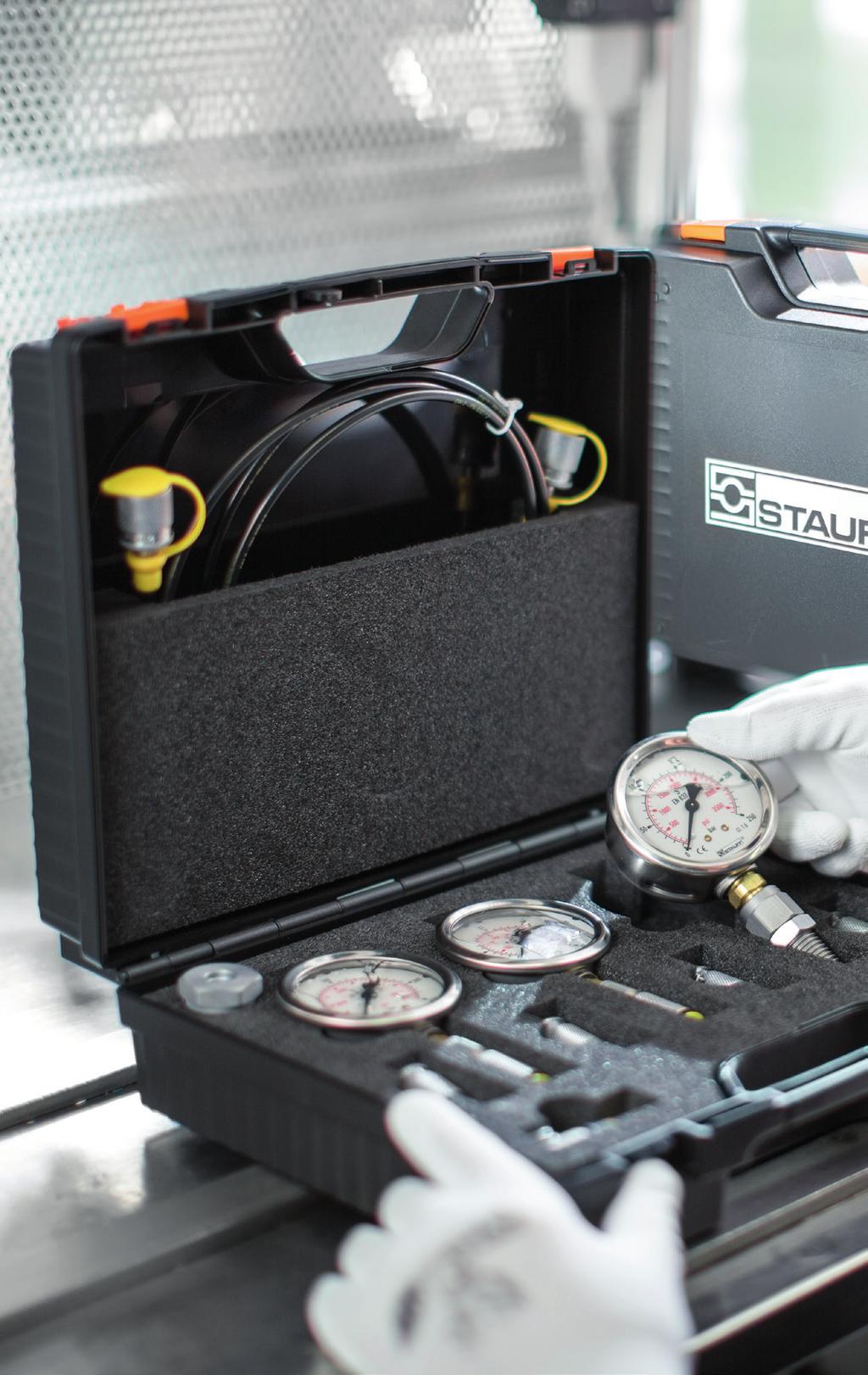
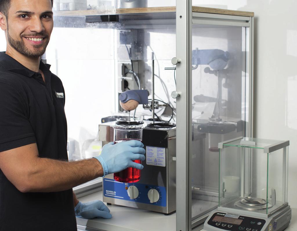
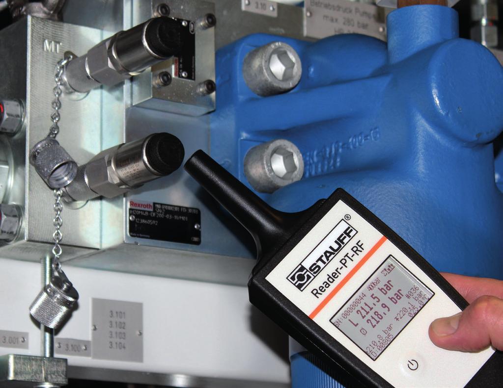
8 Introduction STAUFF Diagtronics With measuring, testing, display and analysis devices and equipment from the STAUFF Diagtronics product range, system operators, maintenance personnel and repair technicians can determine and monitor the essential parameters in mobile and industrial hydraulics: operating pressure, maximum pressure, differential pressure, system temperature, volume flow, contamination and much more. The range includes analogue and digital pressure gauges, that are either supplied individually or as part of practical pressure test kits including the required connection adaptors and accessories, as well as high-performance hand-held hydraulic testers of the PPC series, that have been developed to meet the growing demands of the industry. The PT-RF series of pressure transmitters and readers are an alternative solution for universal pressure measurements for fluid technology applications. The advantages resulting from the use of the non-contact RFID technology for system operators, maintenance personnel and repair technicians are clear: Measurements can be carried very easily, without extensive training and within a few seconds at the press of a button and then documented in a reliable process while temporary opening of the system if not required. Potential hazards for people, machines and the environment as well as ingress of contamination into the system can be effectively excluded. Fluid analysis is a crucial element of any oil management program. Early detection of system contamination can prevent costly repairs and downtime. Portable and permanently installed STAUFF particle counters and monitors enable the precise determination of cleanliness levels of hydraulic media according to international standards. 8 Catalogue 8 Edition 10/2017
9 Introduction Catalogue 8 Edition 10/2017 9

10 Introduction The STAUFF online catalogue centre at provides fast and direct access to digital versions of this as well as other STAUFF product catalogues in all available languages. Online Page-Flip Catalogues Easy navigation through index or the powerful full text search functionality Contents can be shared and forwarded by , printed or downloaded and saved in PDF file format Also suitable for mobile devices The fastest way to the online page-flip catalogue: The links that can be found at the bottom edge of all pages of this product catalogue will lead you directly to the corresponding page in the online page-flip catalogue. In doing so, contents can be searched, shared and forwarded by , printed or downloaded and saved in PDF file format. Scan the QR code next to the direct link with the camera of your mobile device* and also use the functions in this way. * may require a suitable app 10 Catalogue 8 Edition 10/ Download Catalogues Download entire product catalogues and save them in PDF file format Catalogue Request Contact form to request printed copies of the product catalogue as well as digital copies on CD-ROM or US stick 10 Catalogue 8 Edition 10/2017

11 Introduction General information about the companies of STAUFF Group, latest business and product news as well as complete global contact details Comfortable pre-registration for scheduled and unscheduled product returns of of your measuring, testing and analysis devices to STAUFF, e.g. for calibration or service Online database for the qiuck and eady identification and interchange of almost all common brands and types of replacement filter elements Follow STAUFF and keep yourself updated: Facebook Twitter Linkedin Youtube Catalogue 8 Edition 10/
12

13 Pressure Gauges Introduction 14 A Information on the Pressure Equipment Directive 15 Accessories for Pressure Gauges 15 Pressure Gauges Analogue Pressure Gauge SPG Analogue Pressure Test Kit SM-20 / SM-15 Digital Pressure Gauge 20 SPG-DIGI Digital Pressure Test Kit 21 SM-DIGI Catalogue 8 Edition 10/

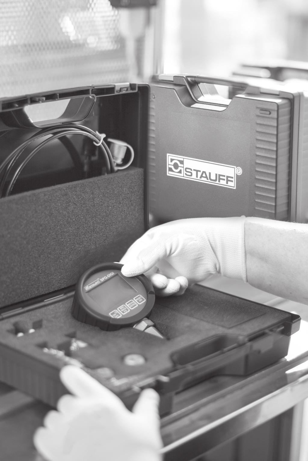
14 Pressure Gauges Pressure Gauges (analogue/digital) and Accessories A Measuring pressure on equipment is indispensable for monitoring and ensuring the smooth functioning and operating safety of these systems. STAUFF offers a variety of simple pressure measuring devices for liquid and gaseous media. These pressure gauges can be used as both stationary or portable devices. STAUFF addresses the very extensive width of possible system pressures and the strict requirements for precision with a variety of pressure gauge types with different measuring ranges. The glycerine filled gauge range is available with various connection ports to fit many different installation needs. The pressure gauges can be purchased alone or in a test kit. The kits can be supplied with gauges with different pressure ranges and adaptors to satisfy any requirement. The analog pressure gauges are primarily designed for permanent installations. STAUFF also offers a digital line for analytical troubleshooting. These digital pressure gauges are also available as a pressure test kit and also make it possible to perform the many different measurement tasks with the help of adaptors and the measuring hose. An important advantage is the possibility to measure pressure peaks with the device, to save them short term and to display them in the display as MIN and MAX values. In addtion to the individual products, the STAUFF measuring devices are also available as kit. 14 Catalogue 8 Edition 10/2017
 conform to the European Standard EN 837-1 and are manufactured and tested according to")
.")

.")
 Multi Station")
 Test Hoses - Gauge Adaptor (see Catalogue 7 - STAUFF Test) Gauge Adaptor (see Catalogue 7 - STAUFF Test)")
15 Pressure Gauges Information on the Pressure Equipment Directive (PED) 97/23/EC Pressure Equipment Directive (PED) Our pressure gauges (SPG) conform to the European Standard EN and are manufactured and tested according to appropriate requirements. Pressure gauges with a full scale value between 0,5 bar and 200 bar / 7.25 PSI and 2900 PSI come under Good Engineering Practice and must not carry a CE mark (section 3, paragraph 3). A Pressure gauges (SPG) with a full scale value of less than 0,5 bar / 7.25 PSI and loose diaphragm sealings do not come under the PED and must not carry a CE mark. Our pressure gauges (SPG) with a full scale value of > 200 bar / 2900 PSI receive a CE mark according to the conformity procedure. The CE mark is attached to the outside of the housing (type designation plate). We are not authorised to CE mark pressure gauges without a company name or a company logo. Pressure Gauges Accessories Single Station Gauge Isolator Valve (see Catalogue 6 - STAUFF Valves) Multi Station Gauge Isolator Valve (see Catalogue 6 - STAUFF Valves) Gauge Isolator Needle Valves (see Catalogue 6 - STAUFF Valves) Test Hoses - Gauge Adaptor (see Catalogue 7 - STAUFF Test) Gauge Adaptor (see Catalogue 7 - STAUFF Test) Direct Gauge Adaptor (see Catalogue 7 - STAUFF Test) Adjustable Gauge Fitting (see Catalogue 7 - STAUFF Test) Catalogue 8 Edition 10/
16 Pressure Gauges Pressure Gauge (analogue) Type SPG A Pressure Gauge (Analogue) Type SPG (Stem Mounting) Pressure Gauge (Analogue) Type SPG (Panel Mounting) Product Description Area of Application Mechanical pressure measurement Features Suitable for hydraulic oil and gaseous media compatible with copper based alloys Available in nominal sizes 63 and 100 mm / 2.5 and 4 in Thread form: for SP (G1/4 and G1/2), NPT (1/4 NPT and 1/2 NPT), SAE (7/16 20 UNF) Stainless Steel (1.4301) housing Acrylic sight glass Glycerine filled Standard dual scales with pressure indication in bar and PSI U-bolt or flange mounting kit on request Note: Please contact STAUFF before you use SPG with other media. Options Protective rubber cap Additional scale readings including personilisation U-bolt and flange mounting kits are available separately as spare parts Technical Data Pressure gauge according to EN Subject to technical modifications Accuracies SPG-063: 1.6 (± 1.6 % FS* as per EN 837-1) SPG-100: 1.0 (± 1.0 % FS* as per EN 837-1) Order Codes SPG P U a Series and Type Stainless Steel Pressure Gauge SPG b Size Ø 63 mm, with G1/4 or 1/4 NPT connection 063 Ø 100 mm, with G1/2 or 1/2 NPT connection 100 c Pressure Ranges Pressure Ranges for style of scale 01 - bar/psi Code Note: Others on request. Information always refer to the pressure setting of the outside scale. Pressure Ranges for style of scale 05 - PSI/bar ,5 bar / PSI (-00001) , bar / -30 inhg... 0 PSI 30HG bar / PSI (-00001) , ,07 bar / -30 inhg PSI bar / PSI ,07 bar / PSI bar / PSI ,14 bar / PSI bar / PSI ,89 bar / PSI bar / PSI ,03 bar / PSI bar / PSI ,79 bar / PSI bar / PSI ,68 bar / PSI bar / PSI ,74 bar / PSI bar / PSI ,37 bar / PSI bar / PSI ,95 bar / PSI bar / PSI ,42 bar / PSI bar / PSI ,90 bar / PSI bar / PSI ,84 bar / PSI bar / PSI ,79 bar / PSI ,74 bar / PSI Code ,69 bar / PSI ,11 bar / PSI ,48 bar / PSI Permissible Temperatures Ambient: -20 C C / -4 F F Media: max. +60 C / max F Protection Ratings IP 65: IP 54 for all manometer SPG-100 and SPG-063 > 16 bar / 232 PSI IP 65 protection rating: Dust tight and protected against water jets for all manometer SPG bar / 232 PSI due to pressure compensation opening IP 54 protection rating: Dust protected and protected against splashing water d Styles of Scales bar / PSI (bar outside/psi inside - standard option Europe) 01 bar 02 PSI 03 PSI / bar (PSI outside/ bar inside - standard option North America) 05 kpa / PSI (kpa outside/ PSI inside) 10 Note: Others on request. e Adaption Stem mounting Panel mounting S P f Process Connection G1/4 (only SPG-063) 04 G1/2 (only SPG-100) 08 1/4 NPT (only SPG-063) N04 1/2 NPT (only SPG-100) N08 7/16 20 UNF (only SPG-063) U04 Note: Others on request. g Accessories No accessory U-bolt assembly Front flange assembly (for panel mount only) Rear flange assembly U-bolt and front flange assembly (for panel mount only) Protective rubber cap (for stem mount only) (none) U F R UF G For further information see Catalogue 7 - STAUFF Test. * FS = Full Scale 16 Catalogue 8 Edition 10/2017
17 Pressure Gauges Pressure Gauge (analogue) Type SPG A ØA E F ØA SW Hex14 (Hex.55) E F ØA ØE ØF SW Hex14 (Hex.55) E F F1 C SW Hex14 (Hex.55) ØD H Ø ØC ØD C G Ø3,5 (3x) (Ø.14) (3x) 120 ØC ØD C Dimensions SPG-063 SPG S... SPG P... U SPG P... F Version Pressure Gauge SPG-063 SPG U SPG F Dimension ( mm /in) ØA Ø ØC ØD ØE ØF C E F F1 G 69 G1/ , /4 NPT /16 20 UNF G1/ ,5 56 1/4 NPT /16 20 UNF G1/ ,5-1/4 NPT /16 20 UNF ØA CHex22 (Hex.87) ØD E H F ØA Ø ØC 30 Hex22 (Hex.87) (1.18) ØD C G E F Ø4,75 (3x) (Ø.19) (3x) ØA ØE ØF 120 Hex22 (Hex.87) ØC 30 (1.18) ØD C E F1 F SPG S... SPG P... U SPG P... F Dimensions SPG-100 Version Pressure Gauge SPG-100 SPG U SPG F Dimension ( mm /in) ØA Ø ØC ØD ØE ØF C E F F1 G 107 G1/ /2 NPT G1/ , /2 NPT G1/ , /2 NPT * FS = Full Scale Dimensional drawings: All dimensions in mm (in). Catalogue 8 Edition 10/

18 Pressure Gauges Pressure Test Kit (analogue) Type SM-20 / SM-15 A Pressure test kit (analogue) with SPG-063 (3x) Pressure test kit (analogue) with SPG-100 (1x) Product Description Order Codes In addition to the individual SPG gauges, the STAUFF Pressure Gauges are also available as part of a pressure test kit. SM xxx/xxx/xxx - W3 The SM Pressure Test Kits are assembled in various versions, in accordance with customer wishes. All pressure test kits are supplied in a handy case with custom-designed foam inserts. Custom kits available upon request. Please contact STAUFF. Please see on page 19 for standard options. a Series and Type Pressure Test Kit, analogue (STAUFF Test 20) SM-20 Pressure Test Kit, analogue (STAUFF Test 15) SM-15 b Number of Pressure Gauges 1 pressure gauge SPG pressure gauges SPG pressure gauges SPG pressure gauge SPG-100 /100-1 c Pressure Ranges bar / PSI (-1) bar / PSI bar / PSI bar / PSI bar / PSI bar / PSI bar / PSI bar / PSI bar / PSI bar / PSI 400 Note: Please indicate pressure ranges in bar. For one pressure gauge please replace xxx. For two pressure gauges please replace xxx/xxx. For three pressure gauges please replace xxx/xxx/xxx. d Material Surface Steel, zinc/nickel plated W3 For further information see Catalogue 7 - STAUFF Test. 18 Catalogue 8 Edition 10/2017
19 Pressure Gauges Standard Option for Pressure Test Kits (analogue) Type SM-20 / SM-15 Series Components Order Codes Series Components Order Codes 1x Test hose (2000 mm length) SMS W3 1x Test hose (2000 mm length) SMS W3 1x Pressure gauge Ø 63 mm SPG-063-xxx-... 1x Pressure gauge Ø 63 mm SPG-063-xxx-... 1x Gauge adaptor G1/4 SMA-20-G1/4--OR-W3 1x Gauge adaptor G1/4 SMA-15-G1/4--OR-W3 SM-20-1-xxx-W3 1x Direct gauge adaptor G1/4 SMD-20-G1/4--OR-W3 1x Direct gauge adaptor G1/4 SMD-15-G1/4--OR-W3 SM-15-1-xxx-W3 1x Test coupling G1/4 SMK-20-G1/4--C-W3 1x Test coupling G1/4 SMK-15-G1/4---W3 1x Test coupling M10 x 1 SMK-20-M10x1--A-W3 1x Test coupling M14 x 1,5 SMK-15-M14x1.5---W3 1x Thread adaptor G3/8 SRS-20-G3/8--W3 1x Thread adaptor G3/8 SRS-15-G3/8--W3 1x Thread adaptor G1/2 SRS-20-G1/2--W3 1x Thread adaptor G1/2 SRS-15-G1/2--W3 xxx/xxx/xxx = pressure ranges see on page 18 (please indicate pressure ranges in bar) Custom kits available upon request. Please contact STAUFF. A Series Components Order Codes Series Components Order Codes 1x Test hose (2000 mm length) SMS W3 1x Test hose (2000 mm length) SMS W3 2x Pressure gauges Ø 63 mm SPG-063-xxx-... 2x Pressure gauges Ø 63 mm SPG-063-xxx-... 1x Gauge adaptor G1/4 SMA-20-G1/4--OR-W3 1x Gauge adaptor G1/4 SMA-15-G1/4--OR-W3 SM-20-2-xxx/xxx-W3 1x Direct gauge adaptor G1/4 SMD-20-G1/4--OR-W3 1x Direct gauge adaptor G1/4 SMD-15-G1/4--OR-W3 SM-15-2-xxx/xxx-W3 1x Test coupling G1/4 SMK-20-G1/4--C-W3 1x Test coupling G1/4 SMK-15-G1/4---W3 1x Test coupling M10 x 1 SMK-20-M10x1--A-W3 1x Test coupling M14 x 1,5 SMK-15-M14x1.5---W3 1x Thread adaptor G3/8 SRS-20-G3/8--W3 1x Thread adaptor G3/8 SRS-15-G3/8--W3 1x Thread adaptor G1/2 SRS-20-G1/2--W3 1x Thread adaptor G1/2 SRS-15-G1/2--W3 xxx/xxx/xxx = pressure ranges see on page 18 (please indicate pressure ranges in bar) Custom kits available upon request. Please contact STAUFF. Series Components Order Codes Series Components Order Codes 2x Test hoses (2000 mm length) SMS W3 2x Test hoses (2000 mm length) SMS W3 3x Pressure gauges Ø 63 mm SPG-063-xxx-... 3x Pressure gauges Ø 63 mm SPG-063-xxx-... 1x Gauge adaptor G1/4 SMA-20-G1/4--OR-W3 1x Gauge adaptor G1/4 SMA-15-G1/4--OR-W3 SM-20-3-xxx/xxx/xxx-W3 2x Direct gauge adaptors G1/4 SMD-20-G1/4--OR-W3 2x Direct gauge adaptors G1/4 SMD-15-G1/4--OR-W3 SM-15-3-xxx/xxx/xxx-W3 3x Test couplings G1/4 SMK-20-G1/4--C-W3 3x Test couplings G1/4 SMK-15-G1/4---W3 3x Test couplings M10 x 1 SMK-20-M10x1--A-W3 3x Test couplings M14 x 1,5 SMK-15-M14x1.5---W3 1x Thread adaptor G3/8 SRS-20-G3/8--W3 1x Thread adaptor G3/8 SRS-15-G3/8--W3 1x Thread adaptor G1/2 SRS-20-G1/2--W3 1x Thread adaptor G1/2 SRS-15-G1/2--W3 xxx/xxx/xxx = pressure ranges see on page 18 (please indicate pressure ranges in bar) Custom kits available upon request. Please contact STAUFF. Series Components Order Codes Series Components Order Codes 1x Test hose (2000 mm length) SMS W3 1x Test hose (2000 mm length) SMS W3 1x Pressure gauge Ø 100 mm SPG-100-xxx-... 1x Pressure gauge Ø 100 mm SPG-100-xxx-... 1x Gauge adaptor G1/2 SMA-20-G1/2--OR-W3 1x Gauge adaptor G1/2 SMA-15-G1/2--OR-W3 SM-20/100-1-xxx-W3 1x Direct gauge adaptor G1/2 SMD-20-G1/2--OR-W3 1x Direct gauge adaptor G1/2 SMD-15-G1/2--OR-W3 SM-15/100-1-xxx-W3 1x Test coupling G1/2 SMK-20-G1/2--C-W3 1x Test coupling G1/4 SMK-15-G1/4---W3 1x Test coupling M10 x 1 SMK-20-M10x1--A-W3 1x Test coupling M14 x 1,5 SMK-15-M14x1.5---W3 1x Thread adaptor G3/8 SRS-20-G3/8--W3 1x Thread adaptor G3/8 SRS-15-G3/8--W3 1x Thread adaptor G1/2 SRS-20-G1/2--W3 1x Thread adaptor G1/2 SRS-15-G1/2--W3 xxx/xxx/xxx = pressure ranges see on page 18 (please indicate pressure ranges in bar) Custom kits available upon request. Please contact STAUFF. Accessories (Connection Adaptors) G 1/4 M16 x 2 G Adaptor Adaption from to Dimension G SDA-20-G1/4-W3 G1/4 M16 x 2 SDA-15-G1/4-W3 G1/4 M16 x 1,5 SDA-12-G1/4-W3 G1/4 S12,65 x 1,5 SDA adaptor Connects the pressure gauge to a test coupling G SAD adaptor Only in conjunction with the G SDA-20-G1/4-W3 adaptor, connects to other test coupling sizes Test coupling STAUFF Test or comparable SAD-20/15--W3 M16 x 2 M16 x 1,5 SAD-20/12--W3 M16 x 2 S12,65 x 1,5 SAD-20/10--W3 M16 x 2 Plug-in system Other adaptors are available. Catalogue 8 Edition 10/
20 Pressure Gauges Digital Pressure Gauge Type SPG-DIGI A Product Description The SPG-DIGI Digital Pressure Gauges are intended to measure and display pressures in hydraulic systems, particularly for oils, lubricants and water. They can display the current measured values, as well as minimum and maximum values, with an accuracy of 0,5 % of full scale. The SPG-DIGI Digital Pressure Gauges are available individually, or as part of a complete pressure test kit. They are very sturdy, reliable, easy to use and come with the CE mark (evidence of conformity compliance). Features ar graph display (drag indicator) ackground lighting Zero correction attery charge display Order Codes a Series and Type Digital Pressure Gauge SPG-DIGI CAL SPG-DIGI b Pressure Ranges bar / PSI bar / PSI bar / PSI bar / PSI 0600 c Process Connection G1/4 7/16 20 UNF U d Calibration Without calibration certificate With calibration certificate (none) CAL Pressure Ranges Version Pressure Range ( bar /PSI) Maximum Pressure ( bar /PSI) urst Pressure ( bar /PSI) Technical Data Materials Housing made of die-cast Zinc with TPE rubber protective covering Wetted parts: Stainless Steel , NR, ceramic Gaskets: NR (una-n ) FKM (Viton ) or EPDM upon request Dimensions and Weight Diameter: 79 mm / 3.11 in Depth: 33 mm / 1.30 in Weight: 540 g / 1.19 Ibs Display Text display 4 1/2-digit Size: 50 x 34 mm / 1.97 x 1.34 in Actual value display: 15 mm /.59 in MIN-/MAX or FS* display: 8 mm /.31 in Units: bar, PSI, Mpa, kpa, mbar Peak pressure measurement with 10 ms sampling rate Lighted measured value display Accuracy ±0,25 % FS* typ. / ±0,5 % FS* max. Resolution: 4096 steps Permissible Temperatures Ambient: -10 C C / +14 F F Media: -20 C C / -4 F F Storage: -20 C C / -4 F F Relative humidity: < 85 % attery life: max hours (operating without lighting, 2 x 1,5 V DC AA (LR6-AA) Alkaline Mignon) Process Connections G1/4 or 7/16 20 UNF made of Stainless Steel Vibration: IEC / Hz / 5 g Shock: IEC / 11 ms / 25 g Load cycles (10 6 ): 100 Protection Rating IP 67 protection rating: Dust tight and protected against powerful water jets; even immersion (up to 1 m / 3.28 ft) in water is possible under defined conditions of pressure and time * FS = Full Scale 20 Catalogue 8 Edition 10/2017
21 Pressure Gauges Pressure Test Kit (digital) Type SM-DIGI A Pressure Test Kit (Digital) Type SM-DIGI Order Codes Product Description Pressure Ranges SM-DIGI CAL a Series and Type Pressure Test Kit, digital pressure gauge SM-DIGI b Adaptor Version Adapts to STAUFF Test 20 (M16 x 2) 20 c Pressure Ranges bar / PSI bar / PSI bar / PSI bar / PSI 0600 d Process Connection G1/4 7/16 20 UNF U e Calibration Without calibration certificate With calibration certificate Version Pressure Range ( bar /PSI) Maximum Pressure ( bar /PSI) urst Pressure ( bar /PSI) (none) CAL In addition to the individual SPG-DIGI devices, the STAUFF Digital Pressure Gauges are also available as part of a pressure test kit. The SM-DIGI pressure test kits are assembled in various versions, in accordance with customer wishes. All pressure test kits are supplied in a handy case with custom-designed foam inserts. Components Standard Option SM-DIGI-20 Digital Pressure Gauge SPG-DIGI Test Hose (2 m / 6.56 ft), M16 x 2, pressure-resistant 600 bar (8702 PSI) SMS W3 Adaptor SDA (G1/4 to M16 x 2) SDA-20-G1/4-W3 Hose Connector SSV-20-W3 Test Coupling SMK-20-G1/4--C-W3 Test Coupling SMK-20-M10x1--A-W3 Thread Adaptor SRS-20-G3/8--W3 Thread Adaptor SRS-20-G1/2--W3 Operating manual (multilingual) on CD Accessories (Connection Adaptors) G 1/4 M16 x 2 G Adaptor Adaption from to Dimension G SDA-20-G1/4-W3 G1/4 M16 x 2 SDA-15-G1/4-W3 G1/4 M16 x 1,5 SDA-12-G1/4-W3 G1/4 S12,65 x 1,5 SDA adaptor Connects the pressure gauge to a test coupling G SAD adaptor Only in conjunction with the G SDA-20-G1/4-W3 adaptor, connects to other test coupling sizes Test coupling STAUFF Test or comparable SAD-20/15--W3 M16 x 2 M16 x 1,5 SAD-20/12--W3 M16 x 2 S12,65 x 1,5 SAD-20/10--W3 M16 x 2 Plug-in system Other adaptors are available. Catalogue 8 Edition 10/


22 Introduction 25 Overview 26 Functional lock Diagrams 27 Hydraulic Testers PPC-04-plus PPC-04-plus-CAN 28 PPC-06/08-plus 29 PPC-Pad Pressure Sensors PPC-04/12-P 34 PPC-CAN-P 35 Temperature Sensors PPC-04/12-T 36 PPC-CAN-T 37 Pressure / Temperature Sensors PPC-04/12-PT 38 PPC-CAN-PT 39


23 Hydraulic Testers Flow Turbine Pressure Transmitter PPC-04/12-SFM 40 Overview 51 PPC-CAN-SFM 41 PT-RF 52 Rotational Speed Sensor PPC-04/12-SDS-CA 42 Reader-PT-RF 53 Current / Voltage / Frequency Converter 43 Complete Systems 54 Sensorconverter-PPC PT-RF-SET Accessories 44 Accumulator Adaptor SAA / SDAA 55 CAN Accessories 45 Flow Indicators CAN Frequency Converter 45 Flow Indicators PPC-CAN-FR SDM / SDMKR Complete Systems PPC-04/06/08-plus-SET 46 PPC-04-CAN-SET 47 PPC-Pad-SET 48 Ordering Tables For analogue Hydraulic Testers 49 For CAN Hydraulic Testers 50 Catalogue 8 Edition 10/
24 Hydraulic Testers 24 Catalogue 8 Edition 10/2017

25 Hydraulic Testers Hydraulic Testers of the PPC Series The STAUFF measuring and test equipment of the PPC series are perfectly suited for measuring all relevant parameters in fluid power systems, including pressure, differential pressure, temperature, flow and rotational speed. Depending on the type, they allow evaluation, storage and further processing in PCs or notebooks. They have been especially developed for the growing needs of system monitoring, troubleshooting and determining measured values in hydraulic and pneumatic systems. The application areas are broad: Industrial hydraulics Mobile, agricultural and forestry hydraulics Marine and offshore hydraulics Chemical and petrochemical industries Energy and air conditioning industries Heating and sanitary industries Among other things, the latest generation of Hydraulic Tester PPC-04-plus is characterised by a simple operation. Even in low-light situations, measured values can be read quickly and reliably from the multi-line, backlit LCD display. The new Hydraulic Tester is available in two versions, either with two inputs for analogue sensors or with a CAN interface for connecting up to three digital sensors. oth versions are equipped with an internal data memory and an US port. They are driven by an internal power supply (Lithium-Ion pack). The Hydraulic Testers of the PPC-06/08-plus series, depending on the type, provide the potential of connecting three or four analogue sensors. Even older sensors of the STAUFF Diagtronics product program or third-party sensors can be used with these units without any problems. oth Hydraulic Testers are equipped with a large data memory and an integrated US port, they can be used for several hours in battery operation. The included PC software allows to show the measured values as numerical values or as curve graphs on PCs or notebooks. The PPC Pad is the highest-performance unit of the PPC series. This portable multi-function hand-held measuring instrument has been especially developed for the increasing fluid technology requirements. STAUFF s CAN bus sensors take advantage of the bus system s automatic sensor recognition to provide an easy-to-install Plug & Play solution. The measured values can be displayed in various presentation styles and make effective solutions-orientated analysis possible. The Hydraulic Testers of the PPC series and their corresponding sensors are also available as calibrated version, they are delivered with a calibration certificate. A subsequent calibration can be ordered by using a special order code. Catalogue 8 Edition 10/
26 Hydraulic Testers Hydraulic Testers of the PPC Series Product Overview Hydraulic Testers Options PPC-04-plus PPC-04-plus-CAN PPC-06-plus PPC-08-plus PPC-Pad Rechargeable attery Number of Sensor Inputs 2 (max. 2 analogue sensors) 1x CAN (max. 3 CAN sensors) 3 4 max x CAN (each 8 sensors) PC Interface US US US US US / Ethernet Online Function Internal Memory Programming of Automatic Measuring Tasks Internal Trigger Function Data Display Display Lightning Curve Printout on Display PC Software Kit Pressure Measurement Temperature Measurement Flow Measurement Rotational Speed Measurement Frequency Measurement Third-Party Sensors Current / Voltage Adaptor STAUFF CAN Sensor = standard, = not available 26 Catalogue 8 Edition 10/2017


 k PPC Connection Cable as a component of the PC Sets PC-SET-06/08-plus-SW-CA (US) l PPC Connection Cable as a component of the PC Sets PC-SET-04-plus-SW-CA (US) m PPC Connection Cable as a")
 j k g a b g g g h h h f i c d e a Hydraulic Tester PPC-04-plus-CAN with CAN interface (1x) b Hydraulic Tester PPC-Pad with two CAN interfaces c CAN")
27 Hydraulic Testers Hydraulic Testers of the PPC Series l k k m a b c d j j j j e f g h i a Hydraulic Tester PPC-04-plus max. two analogue sensors can be connected at the same time b Hydraulic Tester PPC-06-plus max. three analogue sensors can be connected at the same time c Hydraulic Tester PPC-08-plus max. four analogue sensors can be connected at the same time d Hydraulic Tester PPC-Pad max. six analogue sensors can be connected at the same time e Pressure Sensor PPC-04/12-P f Pressure / Temperature Sensor PPC-04/12-PT g Rotational Speed Sensor PPC-04/12-SDS-CA with integrated connection cable, optionally with Contact Adaptor PPC-04/12-SKA-Contact or Focusing Adaptor PPC-04/12-SKA-Focus h Screw-in Temperature Sensor PPC-04/12-T Manual Temperature Sensor PPC-04/12-TSH i Flow Turbine PPC-04/12-SFM with integrated signal converter, for connecting pressure and temperature sensor j 5-pin Connection Cable for sensors PPC-04/12-CA3 (3 m / 9.84 ft), optionally with Extension Cable PPC-04/12-CA5-EXT (5 m / ft) k PPC Connection Cable as a component of the PC Sets PC-SET-06/08-plus-SW-CA (US) l PPC Connection Cable as a component of the PC Sets PC-SET-04-plus-SW-CA (US) m PPC Connection Cable as a component of the PC Sets LAN- or US 2.0-Cable Hydraulic Testers PPC Series (CAN Version) j k g a b g g g h h h f i c d e a Hydraulic Tester PPC-04-plus-CAN with CAN interface (1x) b Hydraulic Tester PPC-Pad with two CAN interfaces c CAN Pressure Sensor PPC-CAN-P d CAN Temperature Sensor PPC-CAN-T e CAN Pressure / Temperature Sensor PPC-CAN-PT f CAN Flow Turbine PPC-CAN-SFM with integrated signal converter, for connecting pressure and temperature sensors g CAN Connection Cable PPC-CAN-CAX h CAN Y-Splitter Cable PPC-CAN-CA-Y i CAN Terminating Resistor PPC-CAN-R j PPC Connection Cable as a component of the PC Sets PC-SET-04-plus-SW-CA (US) k PPC Connection Cable as a component of the PC Sets LAN- or US 2.0-Cable Catalogue 8 Edition 10/
 Product Description Order Codes The PPC-04-plus and PPC-04-plus-CAN Hydraulic Testers have been developed for the growing demands in mobile and industrial hydraulic")
28 Hydraulic Testers Hydraulic Testers Type PPC-04-plus / PPC-04-plus-CAN PPC-04-plus with 2 sensor inputs for max. 2 analogue sensors PPC-04-plus-CAN with CAN interface for max. 3 sensors (max. 50 m / 164 ft cable length) Product Description Order Codes The PPC-04-plus and PPC-04-plus-CAN Hydraulic Testers have been developed for the growing demands in mobile and industrial hydraulic systems. They are perfectly suited for the precise determination of pressure, temperature, volume flow and rotational speed. PPC-O4-plus - CAN - CAL Multi-line, backlit LCD display Max. two analogue sensors can be connected at the same time With CAN interface, max. three digital sensors can be connected at the same time Integrated data memory for data records External storage by using a US memory stick (1 G included) Max. CAN bus length: 50 m / 164 ft (CAN version) a Series and Type Hydraulic Tester b Version Analogue version CAN version Technical Data PPC-04-plus (none) CAN c Calibration Without calibration certificate With calibration certificate Note: Calibration certificate is only available for the analogue Hydraulic Tester PPC-04-plus. (none) CAL The Hydraulic Testers are available in two versions. The PPC-04-plus, analogue version, comes with two inputs for connecting up to two analogue sensors at the same time. The PPC-04-plus-CAN comes with an CAN interface for connecting up to three digital sensors at the same time. oth versions provide automatic sensor recognition, thus making the tedious and often time-consuming parameterization of sensors redundant. The units can be easily operated via the keyboard and the individual device configurations can be viewed and managed. Due to its extremely robust construction and oil-resistant rubber coating, the Hydraulic Testers can withstand impacts, vibrations, dust and moisture (protection class up to IP 67) and is designed for use in particularly harsh conditions. The internal battery (Lithium Ion pack) can be charged via an micro US connection, this connection can be also used to transfer the internally stored datas to a PC or notebook. Furthermore, this connection is also provided for real-time presentation of the measured values on the PC. The PPC-04-plus devices can store up to data records and measured values. The included PPC software is compatible with popular PC operating systems (Windows XP, Windows Vista, Windows 7, Windows 8 and Windows 10 ) and permits various evaluation methods. It is also possible to connect the Pressure Sensors under load, with the equipment switched on. The temperature and volume flow sensors are to be installed in the pipelines. The Rotational Speed Sensor is a non-contacting sensor and uses an optical mark on the rotating parts. Measuring the differential pressure requires two Pressure Sensors with identical measuring ranges. The units are also available as a complete set. See pages 46 / 47 for further information. Materials Housing made of AS in a rubber protective Dimensions and Weight W x H x D: 96 x 172 x 54 mm / 3.78 x 6.77 x 2.13 in Weight: ca. 540 g / 1.19 lbs Measurements / Display Pressure: in bar, PSI, mbar, kpa, MPa Temperature: in C und F Volume flow: in l/min and US GPM Rotational speed: in 1/min and RPM Display: FSTN-LCD, graphic, LED backlit Visible area: 62 x 62 mm / 2.44 x 2.44 in Resolution: 130 x 130 Pixel Power Supply External: attery: Micro US socket, type +5V DC, max ma Lithium Ion pack 3,7 V DC / 2250 mah or 3,7 V DC / 4500 mah CAN version Operating time with the rechargeable battery: approx. 8 hours Sensor Inputs Push-in connection: 5-pol., push-pull or 5-pol., M12x1, SPEEDCON, connector (CAN version) Automatic sensor recognition Sampling rate: 1 ms Accuracy: < ±0,2 % FS* ±1 Digit Permissible Temperatures Ambient: 0 C C / +32 F F Storage: -25 C C / -13 F F Relative humidity: < 80 % CE certified Interfaces US device: US host: Online transmission between unit and PC via PPC-Soft-plus (software) Measured value transmission: ACT/MIN/MAX, min. 5 ms US standard: 2.0, fullspeed Push-in connection: Micro US socket, shielded, type A Connection for US stick, max. 4 G US standard: 2.0, fullspeed, max. 100 ma Push-on connection: Micro US socket, shielded, type Protection Rating IP 54 protection rating: Dust protected and protected against splashing water (CAN version) IP 67 protection rating: Dust tight and protected against splashing water Software A PC set, consisting of a US connection lead, length 1 m / 3.28 ft and the corresponding PC software, is included in the scope of delivery. The measured data and curves can be easiliy transferred and processed by using PPC-Soft-plus software as well as exported to Microsoft Excel. SPEEDCON is a trademark of PHOENIX CONTACT GmbH & Co. KG Dimensional drawings: All dimensions in mm (in). 28 Catalogue 8 Edition 10/2017


29 Hydraulic Testers Hydraulic Testers Type PPC-06-plus / PPC-08-plus Order Codes PPC-08-plus with 4 sensor inputs Technical Data Product Description PPC - 06-plus - CAL a Series and Type Hydraulic Tester b Version With 3 sensor inputs With 4 sensor inputs c Calibration Without calibration certificate With calibration certificate Version No. Integrated Data Memory for Sensor Inputs Measured Value Points Memory Curves 06-plus plus 4 Points Points Software PPC 06-plus 08-plus (none) CAL A PC set, consisting of a US connection lead, length 1,5 m / 4.9 ft and the corresponding PC software, is included in the scope of delivery. The measured data and curves can be easiliy transferred and processed by using PPC-Soft-plus software as well as exported to Microsoft Excel. Material Housing made of fibreglass-reinforced PA Dimensions and Weight W x H x D: 106 x 235 x 53 mm / 4.17 x 9.25 x 2.09 in Weight: 530 g / 1.17 lbs Measurements / Display Pressure: in bar, PSI, mbar, kpa, MPa Temperature: in C and F Volumen flow: in l/min and US GPM Rotational speed: in 1/min and RPM Digital LCD display: 128 x 64 Pixel Visible area: 72 x 40 mm / 2.84 x 1.58 in Automatic numeral height adjustment Numeral height: 6 mm /.24 in with eight-line display Data output for connection to neotebook or PC 12-key membrane keyboard Electromagnetic compatibility (EMC): Emitted interference: DIN EN 50081, Part 1 Interference immunity: DIN EN 50082, Part 2 Auto power off (after 20 minutes) attery charge display Measured Data Memory Variable memory interval (1 ms s) or variable memory time (2 s h) Manual and automatic triggering Power Supply Power supply: 110/230 V AC (50/60 Hz) Rechargeable battery charging unit Internal nickel metal hydride (NiMh) battery 7,2 V / 700 mah Operating time with the rechargeable battery: approx. 8 hours The PPC-06/08-plus Hydraulic Testers have been especially developed for the growing demands of system monitoring and troubleshooting in hydraulic and pneumatic systems. Automatic sensor recognition Larger data memory Possible to record MIN-/MAX values over long periods Internal trigger function External trigger function Online data transmission Display lighting Programming by PC and notebook Integrated US interface The ergonomically designed housing and the LCD display, which sets automatically to the appropriate line size, now allows problem free use even under difficult enviromental conditions. The individual PPC-06-plus and PPC-08-plus Hydraulic Testers differ in the number of sensor inputs (3-channel or 4-channel technology). oth Hydraulic Testers can measure, store and process all relevant hydraulic parameters such as pressure, differential pressure, temperature, rotational speed and flow. The comprehensive programmer options, and the internal memory capacity in particular, allow for diverse measurements, trigger functions or measuring data from third-party sensors. The PPC-06/08-plus devices can store up to measuring value points and curve memory points. The stored values can be transferred using the built-in US interface to a PC or notebook. The included PPC software is compatible with popular PC operating systems (Windows XP, Windows Vista, Windows 7, Windows 8 and Windows 10 ) and permits various evaluation methods. Sensor Inputs (5-Pin) Automatic sensor detection Input signal: V DC (R = 470 kω) Frequency range: 0,5 Hz khz Sampling rate: 1 ms Accuracy: < ±0,25 % FS* Data Output Integrated US port (US 2.0) Online data transmission to a PC Speed individually eligible (5 ms s) The automatic sensor recognition feature makes the PPC-06-plus and the PPC-08-plus Hydraulic Testers easy to operate, and the testers can be individually configured to meet customer requirements without a great programming effort. oth Hydraulic Testers allow the data from third-party sensors to be measured and processed. The units are also available as a complete set. See page 46 for further information. * FS = Full Scale Permissible Temperature Ambient: 0 C C / +32 F F Storage: -25 C C / -13 F F Temperature error: < 0,02 % / C Relative humidity: < 80 % CE certified IP 54 protection rating: Dust protected and protected against splashing water Catalogue 8 Edition 10/
30 Hydraulic Testers Hydraulic Tester Type PPC-Pad Product Description The application possibilities for hydraulics have recently increased throughout all areas of drive and control systems. This trend has been particularly noticeable in the sectors of machine, plant and automotive construction. At the same time, hydraulics and electronics have become increasingly intertwined. STAUFF s hand-held measuring instrument PPC Pad helps you to deal with these new trends. It has never been so easy to follow the complex processes in these sectors with measurement, display and analysis. Potential uses include preventative maintenance, commissioning, troubleshooting and machine optimization. The expanded requirements of these modern applications (such as the increased number of measurement points, longer cable lengths and high noise immunity) have driven further development of the CAN bus. STAUFF s CAN bus sensors now take advantage of the bus system s automatic sensor recognition to provide an easy-toinstall Plug & Play solution (max. CAN bus length 100 m / 328 ft). Compatibility with existing diagnostic sensors is also provided. Our proven storage strategy is focused on MIN and MAX value measurements. Combined with a wide variety of value presentation styles, these features make effective solutions oriented analysis possible. The PPC-Soft-plus PC software offers additional methods for analysis, control and remote maintenance using LAN and US connections. Together with this software, the PPC Pad is a truly user-friendly measuring instrument that can be used for any type of diagnostics application. Features Portable multi-function hand-held measuring instrument Pressure, temperature, flow and speed can be measured, monitored and analysed Measurement and display of over 50 channels Measured value display: numerical, bar graph, pointer, curve graph Project templates can be saved and loaded Interfaces: CAN, LAN, US Total memory with up to 1 billion measured values Measured data can be (automatically) recorded, saved and analysed with the PPC-Soft-plus PC software and a LAN or US connection Max. CAN bus length: 100 m / 328 ft Scope of Delivery Hydraulic Tester PPC Pad Installed handle 24 V DC / 2,5 A Power Supply incl. country-specific Adaptor M8 x 1 / 4-pin (digital in/out) US 2.0 cable (2 m / 6.56 ft) LAN cable (5 m / ft) Operating instructions PC software MicroSD memory card M12 cable socket for ma / V aux. sensors Technical Data See page 31 for technical information. Order Codes Hydraulic Tester Version Version PPC-Pad CAL a Series and Type Hydraulic Tester CAN Sensor Inputs 2 networks each with 8 sensors max. Sensor Inputs with Aux. Sensor Recognition Sensor Input STAUFF (Analogue) (Analogue) PPC-Pad PPC-Pad PPC-Pad PPC-Pad b Version PPC-Pad PPC-Pad PPC-Pad c Calibration (only -102 / -103) Without calibration certificate With calibration certificate (none) CAL 30 Catalogue 8 Edition 10/2017
 Inputs / Outputs CAN sensor inputs: 1 digital trigger input: 2 CAN bus networks each with 8 sensors and max.")
31 Hydraulic Testers Hydraulic Tester Type PPC-Pad Technical Data (General) Materials Housing: Protective Sleeve: AS/PC (Thermoplastic) TPE (Thermoplastic Elastomer) Dimensions and Weight W x H x D: 257 x 181 x 75 mm / x 7.13 x 2.95 in Weight: 1550 g / 3.4 lbs (basic model) Inputs / Outputs CAN sensor inputs: 1 digital trigger input: 2 CAN bus networks each with 8 sensors and max. 16 channels (for STAUFF CAN bus sensors) Scanning rate: 1 ms = 1000 measured values/sec. M12x1 push-in connector, 5-pin with SPEEDCON Scanning rate: 1 ms Input impedance: 1 kω Active high: > V DC Active low: <1 V DC isolated 1 digital trigger output: Scanning rate: 1 ms Max.switching signal: +24 V DC/max. 20 ma isolated Push-in connector for digital input and output: M8 x 1 / 4-pin, push-in connector Module Slots 2, for input module, flexible placement possible Slot 1 = IN1, IN2, IN3, IN4/5 Slot 2 = IN6, IN7, IN8, IN9/10 (expandable only by STAUFF) Display FT-LCD colour graphic display Visible area: 115 x 86 mm/ 4.53 x 3.39 in Resolution: 640 x 480 Pixel Interface US device: Online data transmission between unit and PC via PPC-Soft-plus Measured value transmission: ACT/MIN/MAX US standard: 2.0, fullspeed Push-in connection: US socket, shielded, type US host: Ethernet: Connection for mass storage devices such as US memory stick or removeable hard disc standard: 2.0, fullspeed, 100 ma max. Push-in connection: US socket, shielded, type A Online data transmission between unit and PC via PPC-Soft-plus and remote control Measured value transmission: ACT/MIN/MAX standard: 10, 100 Mbit/s, IEEE (10/100 base T) Push-in connection: RJ45, socket, shielded Functions Measurement: ACT/MIN/MAX avlues Measured value display: Numerical, bar graph, pointer, curve graph Measuring functions: Start/stop, points, trigger Trigger: Pre-trigger Remote operation via the Ethernet Acoustic notification at any incident Slope, manual, level, window, time, logic (interconnection of up to two events for the measurement start and stop) Measured Data Memory For storing measured values, project data and screenshots Memory capacity: Memory format: Memory interval: Memory duration: Internal: External SD memory: 4 million measured values per measurement Total measured value memory >1 billion measued values ACT/MIN/MAX 1 ms to 24 h 1 ms to 300 h (trigger measurement) 64 M (approx. 32 million measured values) MicroSD memory card incl. in standard shipment Slot: MicroSD memory card Ambient Conditions Operating temperature: 0 C +50 C / +32 F F Storage temperature: -25 C +60 C / -13 F F Relative humidity: < 80 % Environmental test: IEC (1 m, free fall) Power Supply Internal: Protection Rating IP 64 protection rating: Lithium Ion pack, +7.4 V DC / 4500 mah attery charging circuit/operating time with 3 CAN sensors: > 8 h Dust tight and protected against splashing water Technical Data (for PPC-Pad-102 and 103) Input with Sensor Recognition 3 or 6 sensor inputs (up to 6 or 12 analogue measurement channels) with sensor recognition (p/t/q/n) for PPC sensors Push-in connection: 5-pin, push-pull, combination panel plug/socket Scanning rate: 1 ms = 1000 measured values/sec. For the PPC-04/12-PT combined Pressure/Temperature Sensor, there is an additional temperature channel for each sensor input Temperature scanning: 1 s Inputs for Auxiliary Sensors 2 analogue sensor inputs:for measuring current and voltage Scanning rate: 1 ms = 1000 measured values/sec. Voltage measuring range: V DC (freely configurable) Current measuring range: 0/4 20 ma Supply external sensors: V DC/max. 100 ma Push-in connection: M12x1, 5-pin socket FAST mode: Scanning rate: 0.1 ms = measured values/sec. only one auxiliary sensor input is useable Accuracy +0,02 % per C External US mass memory device: up to 40 G SPEEDCON ist ein Markenzeichen der PHOENIX CONTACT GmbH & Co. KG Catalogue 8 Edition 10/


 automatic sensor recognition m PC interface (US 2.")
32 Hydraulic Testers Hydraulic Tester Type PPC-Pad i h m l a g b c j f d k n e Functional Description a High protection from moisture and dirt due to cover caps and a rubber protective sleeve, protection class IP 64 b Illuminated display for good readability in any situation c Protection of the housing, affording usage in tough enviroments and absorption of shocks d ig 5.7 in colour display for clearly viewing the extensive information e Intuitive operation due to clear-cut control elements and function-oriented keys f Ergonomic housing shape ensures convenient portability and long operating times g Large keyboard and fonts for easy operation and readability h Portabel multi-function hand-held measuring instrument strong in design and tough in operation i Easy to carry and hang up with carrying strip j 110 / 240 V AC power supply, battery life 8 hours, recharging time 3 hours k 2 x CAN bus networks with each 16 channels l Modular design for up to 6 analogue sensors or 2 highspeed channels (0,1 ms) automatic sensor recognition m PC interface (US 2.0); ACT/MIN/MAX measured value transmission to the PPC-Soft-plus software, terminal for US mass storage devices n LAN interface for remote monitoring, MicroSD memory card for storage enlargement Connection of Analogue Sensors / CAN Sensors Connection Cable (analogue) PPC-04/12-CA3 Analogue Pressure / Temperature Sensor PPC-04/12-PT Analogue Pressure Sensor PPC-04/12-P Analogue Temperature Sensor PPC-04/12-T Analogue Flow Turbine PPC-04/12-SFM CAN Connection Cable PPC-CAN-CAX CAN Terminating Resistor PPC-CAN-R CAN Connection Cable PPC-CAN-CAX CAN Y-Junction PPC-CAN-CA-Y CAN Y-Junction PPC-CAN-CA-Y Each CAN bus network (CAN X, CAN Y) can handle up to 8 sensors CAN Terminating Resistor PPC-CAN-R CAN Pressure / Temperature Sensor PPC-CAN-PT CAN Flow Turbine PPC-CAN-SFM 32 CAN Temperature Sensor PPC-CAN-T CAN Pressure Sensor PPC-CAN-P Catalogue 8 Edition 10/2017


33 Hydraulic Testers Hydraulic Tester PPC-Pad-Display Display of measured values as figures and bars Fixing of alarm ranges in green, yellow and red Trailing pointer function with MIN and MAX values Up to 4 channels in one large-format display Simultaneous display of ACT, MIN and MAX values Information lines of current settings, events and views Individual measurement channel identifier Large-area pointer display of measured values Trailing pointer for MIN and MAX values Alarm range in green, yellow and red Further channels can be called up with the arrow keys Up to 8 channels in one display Colour allocation of the individual channels Uniform headings with measurement titels, sensors connected, interfaces, date, time and battery condition indicator Display can be changed between MIN and MAX values and full scale Up to 8 channels in one graph display Fine, precise graph image thanks to high definition display Choice between ACT and MIN/MAX value display Automatic and manual scaling of the time axis for optimum measured value display Catalogue 8 Edition 10/
34 Hydraulic Testers Pressure Sensor Type PPC-04/12-P Ø22 (.87) Ø12 (.47) SDA-20-G1/4-W3 G1/4G 1/2 SAD-20/15--W3 M16 10 (.39) 55,5 (2.19) M16 53,6 (2.11) (2,11) M16x1,5 39 (1.53) (1,46) M16 M16 12 (.47) G1/4 39 (1.53) (1,53) 37 (1.45) (1,45) Ø18,8 (.74) S 12,65x1,5 SAD-20/12--W3 SAD-20/10--W3 Product Description The Pressure Sensors PPC-04/12-P can be used with all analogue Hydraulic Testers of the PPC series, due to their 5-pin connection. Due their sturdy Stainless Steel design, the quick response times (< 1 ms) and the high accuracy (±0,25% FS* typ.) with automatic sensor recognition, the Pressure Sensors are a reliable and flexible solution for the Hydraulic Testers of the PPC series. Note: A Connection Cable PPC-04/12-CA3 (3 m / 9.84 ft) is needed to connect the Pressure Sensor PPC-04/12-P to the current Hydraulic Testers. An Extension Cable PPC-04/12- CA5-EXT (5 m / ft) is also available as an option. See page 44 for further information. Order Codes a Series and Type Pressure Sensor b Version See table Pressure Range and Accuracies PPC-04/12-P CAL PPC-04/12-P c Calibration Without calibration certificate With calibration certificate (none) CAL PPC-04/12-P Pressure Measurement yes Temperature Measurement no Process Connection G1/4 Type analogue 5-pin connection Technical Data Sturdy Stainless Steel housing (1.4301) FKM (Viton ) gasket Weight: 85 g /.19 lbs Suitable for gases and liquids (in the case of aggressive media, only after contactation) 5-pin connection Pressure connection G1/4 (without adaptor) Ambient Conditions Media temperature: -25 C C /-13 F F Ambient temperature: -25 C C / -13 F F Storage temperature: -25 C C / -13 F F Load cycles (10 6 ): 100 Version Sensor PPC-04/12-P- Pressure Range and Accuracies Pressure Measuring Range ( bar /PSI) Type of Measurement Maximum Pressure ( bar /PSI) urst Pressure ( bar /PSI) Accuracy (±% FS*) typ Relative pressure ,25 0, Absolute pressure ,25 0, Absolute pressure ,25 0, Absolute pressure ,25 0, Absolute pressure ,25 0, ** Absolute pressure ,25 0,5 * FS = Full Scale ** Pressure peaks up to 1000 bar / PSI Connection Adaptors for PPC Sensors Accuracy (±% FS*) max. Electrical Data Input voltage: V DC Output signal: V DC Response time: 1 ms Long-term stability: < 0,2 % FS* /a Vibration loading: acc. to IEC (20 g) Shock loading: acc. to IEC (50 g) In addition to the Pressure Sensors, different adaptors and adaptor sets are available that not only connect to the STAUFF Test 20 (SDA-20-G1/4-W3), but also to the Test Couplings of the STAUFF Test 15/12/10 series (SAD-20/15--W3, SAD-20/12--W3, SAD-20/10--W3). For further information please see Catalogue 7 - STAUFF Test. Dimensional drawings: All dimensions in mm (in). 34 Catalogue 8 Edition 10/2017
35 Hydraulic Testers CAN Pressure Sensor Type PPC-CAN-P SDA-20-G1/4-W3 G1/4G 1/2 SAD-20/15--W3 M16 Ø22 (.87) Ø10,6 (.47) 53,6 (2.11) (2,11) 39 (1.53) (1,46) 10,5 (.41) M16 M16 M16x1,5 M16 45,3 (1.78) 39 (1.53) (1,53) 37 (1.45) (1,45) 12 (.47) G1/4 S 12,65x1,5 SAD-20/12--W3 SAD-20/10--W3 Ø18,9 (.74) Order Codes a Series and Type CAN Pressure Sensor b Version See table Pressure Range and Accuracies PPC-CAN-P CAL PPC-CAN-P c Calibration Without calibration certificate With calibration certificate (none) CAL Product Description The CAN Pressure Sensors PPC-CAN-P are specially designed for use with the CAN Hydraulic Testers. These sensors are using the CANopen protocol to transfer the measurement values to the CAN Hydraulic Testers. Most technical details are the same as with the Pressure Sensors. Due their sturdy Stainless Steel design, the quick response times (< 1 ms) and the high accuracy (±0,25% FS* typ.) with automatic sensor recognition, the CAN Pressure Sensors are a reliable and flexible solution for the CAN Hydraulic Tester. The status of the sensor is indicated via LED. Connecting the CAN Pressure Sensor to the CAN Hydraulic Tester a CAN Connection Cable and a CAN Terminating Resistor is needed. See page 45 for further information. Version Sensor PPC-CAN-P- Pressure Range and Accuracies Pressure Measuring Range ( bar /PSI) Type of Measurement Maximum Pressure ( bar /PSI) urst Pressure ( bar /PSI) Accuracy (±% FS*) typ Relative pressure ,25 0, Absolute pressure ,25 0, Absolute pressure ,25 0, Absolute pressure ,25 0, Absolute pressure ,25 0, ** Absolute pressure ,25 0,5 * FS = Full Scale **Pressure peaks up to 1000 bar / PSI Connection Adaptors for PPC Sensors In addition to the CAN Pressure Sensors, different adaptors and adaptor sets are available that not only connect to the STAUFF Test 20 (SDA-20-G1/4-W3), but also to the Test Accuracy (±% FS*) max. Couplings of the STAUFF Test 15/12/10 series (SAD-20/15--W3, SAD-20/12--W3, SAD-20/10--W3). For further information please see Catalogue 7 - STAUFF Test. PPC-CAN-P Pressure Measurement yes Temperature Measurement no Process Connection G1/4 Type CAN connection 5-pin, M12x1 Technical Data Sturdy Stainless Steel housing (1.4301) FKM (Viton ) gasket) Sensor identification LED Weight: 85 g /.19 lbs Suitable for gases and liquids (in the case of aggressive media, only after contactation) 5-pin SPEEDCON connection plug Pressure connection G1/4 (without adaptor) Ambient Conditions Media temperature: -25 C C /-13 F F Ambient temperature: -25 C C / -13 F F Storage temperature: -25 C C / -13 F F Load cycles (10 6 ): 100 CANopen Interface CANopen protocol profile DS406 v3.2 with manufacturer-specific additions LSS service DS305 v2.0 Electrical Data Response time: 1 ms Long-term stability: < 0,2 % FS* /a Vibration loading: acc. to IEC (20 g) Shock loading: acc. to IEC (50 g) SPEEDCON is a trademark of PHOENIX CONTACT GmbH & Co. KG Dimensional drawings: All dimensions in mm (in). Catalogue 8 Edition 10/
36 Hydraulic Testers Temperature Sensor Type PPC-04/12-T Ø23 (.91) Ø22 (.87) M10 44 (1.73) SW17 (Hex.67) 9 (.35) 12 (.47) SW22 (Hex.87) 19 (.75) 360 (14.17) 19 (.75) 275 (10.83) Ø8,5 M10x1 (.33) Ø13 (.51) G1/4 Ø18,8 (.74) Ø8,5 (.33) Screw-in Temperature Sensor (T) Process Connection M10x1 Process Connection G1/4 Ø4 (.16) Rod-type Temperature Sensor (TSH) Product Description Order Codes The Screw-in Temperature Sensors PPC-04/12-T measure current temperature directly in the pipeline and are compatible with the Flow Turbine PPC-04/12-SFM and the Straight Threaded Joint SGV-16S-G-W3 (only process connection M10x1, see figure below). See product information of Flow Turbine on page 40. The Rod-type Temperature Sensor PPC-04/12-TSH is especially designed to determine the media temperatures in tanks and containers. Note: A Connection Cable PPC-04/12-CA3 (3 m / 9.84 ft) is needed to connect the Temperature Sensor PPC-04/12-T or -TSH to the current Hydraulic Testers. An Extension Cable PPC-04/12-CA5-EXT (5 m / ft) is also available as an option. See page 44 for further information. PPC-04/12-T Pressure Measurement no Temperature Measurement yes Process Connection M10x1 or G1/4 Type analogue 5-pin connection PPC-04/12-T-M02 with SGV-16S-G-W3 For further information please see Catalogue 7 - STAUFF Test. a Series and Type Temperature Sensor b Version Screw-in Rod-type Technical Data PPC-04/12 - T - M02 - CAL PPC-04/12 Suitable for liquids (in the case of aggressive media only after contactation) 5-pin connection Materials Housing (T): Stainless Steel Gaskets (T): FKM (Viton ) Rod (TSH): Stainless Steel Handle (TSH): Delrin Weight Screw-in (T) M02 (M10x1): 04 (G1/4): Rod-type (TSH): 70 g /.15 lbs 55 g /.12 lbs 120 g /.26 lbs Connection STAUFF Test connection SGV-16S-G-W3 in the pipeline (only M10x1) Screw-in thread (T): M10x1 or G1/4 (see figure) Screw-in thread (TSH): M10 T TSH Ambient Conditions (Screw-in Temperature Sensor) Media temperature: -40 C C / -40 F F Ambient temperature: -40 C C / -40 F F Storage temperature: -40 C C / -40 F F Ambient Conditions (Rod-type Temperature Sensor) Media temperature: -25 C C / -13 F F Ambient temperature: -25 C C / -13 F F Storage temperature: -25 C C / -13 F F c Process Connection (only for Version T) M10x1 M02 G1/4 04 d Calibration Without calibration certificate With calibration certificate (none) CAL Measuring Range Measuring range (T): -40 C C / -40 F F Measuring range (TSH): -25 C C / -13 F F Operating pressure (T): 630 bar / 9137 PSI Maximum pressure (T): 800 bar / PSI urst pressure (T): 2150 bar / PSI Accuracy: ±1 % FS Electrical Data Input signal: V DC Output signal: V DC Response time (T) M02 (M10x1): T50 4 s, T90 14 s 04 (G1/4): T50 4 s, T90 12 s Response time (TSH): T90 9,1 s Vibration loading: acc. to IEC (20 g) Shock loading: acc. to IEC (50 g) * FS = Full Scale Dimensional drawings: All dimensions in mm (in). 36 Catalogue 8 Edition 10/2017
37 Hydraulic Testers Ø22 (.87) M12x1 CAN Temperature Sensor Type PPC-CAN-T SW17 (Hex.67) 9 (.35) 12 (.47) SW22 (Hex.87) 45 (1.77) 19 (.75) 19 (.75) Ø8,5 M10x1 (.33) Ø13 (.51) G1/4 Ø18,8 (.74) Ø8,5 (.33) Process Connection M10x1 Process Connection G1/4 Order Codes a Series and Type CAN Temperature Sensor b Version Screw-in PPC-CAN - T - M02 - CAL PPC-CAN T c Process Connection (only for Version T) M10x1 M02 G1/4 04 d Calibration Without calibration certificate With calibration certificate (none) CAL Product Description The CAN Temperature Sensor PPC-CAN-T are specially designed for use with the CAN Hydraulic Testers. This sensor is using the CANopen protocol to transfer the measurement values to the CAN Hydraulic Testers. The PPC-CAN-T is compatible with the CAN Flow Turbine PPC-CAN-SFM and the Straight Threaded Joint SGV-16S-G-W3 (only process connection M10x1, see figure below). See product information of CAN Flow Turbine on page 41. Most technical details are the same as with the Temperature Sensor PPC-04/12-T. Due their sturdy Stainless Steel design with automatic sensor recognition, the CAN Temperature Sensor is a reliable and flexible solution for the CAN Hydraulic Tester. The status of the sensor is indicated via LED. Technical Data Suitable for liquids (in the case of aggressive media only after contactation) 5-pin SPEEDCON connection plug Sensor identification LED Materials Housing: Gaskets: Weight M02 (M10x1): 04 (G1/4): Stainless Steel FKM (Viton ) 70 g /.15 lbs 55 g /.12 lbs Ambient Conditions Media temperature: -40 C C / -40 F F Ambient temperature: -40 C C / -40 F F Storage temperature: -40 C C / -40 F F CANopen Interface CANopen protocol profile DS301, Typ 2.0A with manufacturer-specific additions LSS service DS305 v2.0 Electrical Data Output signal: CAN bus Response time M02 (M10x1): T50 4 s, T90 12 s 04 (G1/4): T50 4 s, T90 14 s Vibration loading: acc. to IEC (20 g) Shock loading: acc. to IEC (50 g) Connecting the CAN Temperature Sensor to the CAN Hydraulic Tester a CAN Connection Cable and a CAN Terminating Resistor is needed. See page 45 for further information. PPC-CAN-T Pressure Measurement no Temperature Measurement yes Process Connection M10x1 or G1/4 Type CAN connection 5-Pin, M12x1 PPC-CAN-T-M02 with SGV-16S-G-W3 For further information please see Catalogue 7 - STAUFF Test. Measuring Range Measuring range: -40 C C / -40 F F Operating pressure: 630 bar / 9137 PSI Maximum pressure: 800 bar / PSI urst pressure: 2150 bar / PSI Accuracy: ±0,66 % FS * FS = Full Scale SPEEDCON is a trademark of PHOENIX CONTACT GmbH & Co. KG Dimensional drawings: All dimensions in mm (in). Catalogue 8 Edition 10/
 M16 M16 M16x1,5 M16 16,5 (.65) 14 (.55) 39 (1.53) (1,53) 37 (1.45) (1,45) G1/2 Ø26 (1.")
38 Hydraulic Testers Pressure / Temperature Sensor Type PPC-04/12-PT Ø26,9 (1.06) Ø12 (.04) 10,5 (.41) SDA-20-G1/2-W3 G 1/2 53,6 (2.11) (2,11) SAD-20/15--W3 M16 39 (1.53) (1,46) 68,6 (2.70) M16 M16 M16x1,5 M16 16,5 (.65) 14 (.55) 39 (1.53) (1,53) 37 (1.45) (1,45) G1/2 Ø26 (1.02) S 12,65x1,5 SAD-20/12--W3 SAD-20/10--W3 Product Description Order Codes The Pressure / Temperature Sensor PPC-04/12-PT can be used with all Hydraulic Testers of the PPC series, due to the 5-pin connection. This sensor is able to measure and display temperatures on the Hydraulic Testers. Due the sturdy Stainless Steel design, the quick response time (< 1 ms) and the high accuracy (±0,25% FS* typ.) with automatic sensor recognition, the Pressure / Temperature Sensor is a reliable and flexible solution for the Hydraulic Testers of the PPC series. Note: A Connection Cable PPC-04/12-CA3 (3 m / 9.84 ft) is needed to connect the Pressure / Temperature Sensor to the current Hydraulic Testers. An Extension Cable PPC-04/12- CA5-EXT (5 m / ft) is also available as an option. See page 44 for further information. PPC-04/12-PT- Pressure Measurement yes Temperature Measurement yes Process Connection G1/2 Type analogue 5-pin connection Technical Data Sturdy Stainless Steel housing (1.4301) FKM (Viton ) gasket Weight: 200 g /.44 lbs Suitable for gases and liquids (in the case of aggressive media, only after contactation) 5-Pin connection Pressure connection G1/2 (without adaptor) a Series and Type Pressure / Temperature Sensor b Version See table Pressure Range and Accuracies PPC-04/12-PT - 015/2 - CAL PPC-04/12-PT Version Pressure Range and Accuracies Sensor PPC-04/12-PT- Pressure Measuring Range ( bar /PSI) Type of Measurement Maximum Pressure ( bar /PSI) 015/ Relative pressure 060/ Absolute pressure 150/ Absolute pressure 400/ Absolute pressure 600/ Absolute pressure 601/ ** Absolute pressure c Calibration Without calibration certificate With calibration certificate urst Pressure ( bar /PSI) Accuracy (±% FS*) typ. Accuracy (±% FS*) max. Temperature Measuring Range ( C/ F) ,25 0, ,25 0, ,25 0, ,25 0, ,25 0, ,25 0, * FS = Full Scale ** Pressure peaks up to 1000 bar / PSI (none) CAL Accuracy (±% FS*) 1,5 1,5 1,5 1,5 1,5 1,5 Ambient Conditions Media temperature: -25 C C /-13 F F Ambient temperature: -25 C C / -13 F F Storage temperature: -25 C C / -13 F F Compensated range: 0 C C / +32 F F Load cycles (10 6 ): 100 Electrical Data Input voltage: V DC Output signal: V DC Response time: 1 ms Long-term stability: < 0,2 % FS* /a Vibration loading: acc. to IEC (20g) Shock loading: acc. to IEC (50g) Connection Adaptors for PPC Sensors In addition to the Pressure / Temperature Sensors, different adaptors and adaptor sets are available that not only connect to the STAUFF Test 20 (SDA-20-G1/2-W3), but also to the Test Couplings of the STAUFF Test 15/12/10 series (SAD-20/15--W3, SAD-20/12--W3, SAD-20/10--W3). For further information please see Catalogue 7 - STAUFF Test. Dimensional drawings: All dimensions in mm (in). 38 Catalogue 8 Edition 10/2017
39 Hydraulic Testers SDA-20-G1/2-W3 G 1/2 SAD-20/15--W3 M16 Ø26,9 (1.06) Ø10,6 (.47) CAN Pressure / Temperature Sensor Typ PPC-CAN-PT 53,6 (2.11) (2,11) 39 (1.53) (1,46) M16 M16 M16x1,5 M16 39 (1.53) (1,53) 37 (1.45) (1,45) 68,1 (2.68) 16,5 (.65) 14 (.55) 11,8 (.46) G1/2 S 12,65x1,5 SAD-20/12--W3 SAD-20/10--W3 Ø26,8 (1.06) Order Codes Product Description a Series and Type CAN Pressure / Temperature Sensor b Version See table Pressure Range and Accuracies PPC-CAN-PT CAL PPC-CAN-PT c Calibration Without calibration certificate With calibration certificate (none) CAL The CAN Pressure / Temperature Sensors PPC-CAN-PT are specially designed for use with the CAN Hydraulic Testers. This sensor is using the CANopen protocol to transfer the measurement values to the CAN Hydraulic Testers. Most technical details are the same as with the Pressure / Temperature Sensor PPC-04/12-PT. The CAN sensor is able to measure and display temperatures on the CAN Hydraulic Testers. Due the sturdy Stainless Steel design, the quick response time (< 1 ms) and the high accuracy (±0,25% FS* typ.) with automatic sensor recognition, the pressure / temperature sensor is a reliable and flexible solution for the CAN Hydraulic Tester. The status of the sensor is indicated via LED. Version Sensor PPC-CAN-PT- Pressure Range and Accuracies Pressure Measuring Range ( bar /PSI) Type of Measurement Maximum Pressure ( bar /PSI) urst Pressure ( bar /PSI) Accuracy (±% FS*) typ. Accuracy (±% FS*) max. Temperature Measuring Range ( C/ F) Accuracy (±% FS*) Relative ±2K typ./ 0,25 0, pressure ±3K max Absolute ±2K typ./ 0,25 0, pressure ±3K max Absolute ±2K typ./ 0,25 0, pressure ±3K max Absolute ±2K typ./ 0,25 0, pressure ±3K max Absolute ±2K typ./ 0,25 0, pressure ±3K max ** Absolute ±2K typ./ 0,25 0, pressure ±3K max. * FS = Full Scale ** Pressure peaks up to 1000 bar / PSI Connection Adaptors for PPC Sensors In addition to the CAN Pressure / Temperature Sensors, different adaptors and adaptor sets are available that not only connect to the STAUFF Test 20 (SDA-20-G1/2-W3), but also to the Test Couplings of the STAUFF Test 15/12/10 series (SAD-20/15--W3, SAD-20/12--W3, SAD-20/10--W3). For further information please see Catalogue 7 - STAUFF Test. Connecting the CAN Pressure / Temperature Sensor to the CAN Hydraulic Tester a CAN Connection Cable and a CAN Terminating Resistor is needed. See page 45 for further information. PPC-CAN-PT Pressure Measurement yes Temperature Measurement yes Process Connection G1/2 Type CAN connection 5-pin, M12x1 Technical Data Sturdy Stainless Steel housing (1.4301) FKM (Viton ) gasket Sensor identification LED Weight: 200 g /.44 lbs Suitable for gases and liquids (in the case of aggressive media, only after contactation) 5-pin SPEEDCON connection plug Pressure connection G1/2 (without adaptor) Ambient Conditions Media temperature: -25 C C /-13 F F Ambient temperature: -25 C C / -13 F F Storage temperature: -25 C C / -13 F F Compensated range: 0 C C / +32 F F Load cycles (10 6 ): 100 CANopen Interfaces CANopen protocol profile DS406 v3.2 with manufacturer-specific additions LSS service DS305 v2.0 Electrical Data Response time: Vibration loading: Shock loading: 1 ms acc. to IEC (20g) acc. to IEC (50g) SPEEDCON is a trademark of PHOENIX CONTACT GmbH & Co. KG Dimensional drawings: All dimensions in mm (in). Catalogue 8 Edition 10/

40 Hydraulic Testers Flow Turbine Type PPC-04/12-SFM Test coupling, pressure sensor connection (M16 x 2) Signal converter H Temperature sensor connection (M10 x 1) G D L Recommended direction of flow Product Description The PPC-04/12-SFM Flow Turbine is permanently installed in the pipeline. The oil flow rotates the internal axial turnine. The frequencies generated are processed by digital electronics (a signal converter). Interferences caused by flow effects are compensated by this process. The signal converter is now directly integrated into the Flow Turbine. This allows even simpler operation and supports permanent coupling of the turbine and signal converter components that are matched to one another. The Flow Turbine also improves the response time (from previously 400 ms to 50 ms) and increases the measuring accuray. The PPC-04/12-SFM is available in five versions for various flow speeds. A Pressure Sensor PPC-04/12-P (see page 34) can be connected in parallel to the Flow Turbine by way of the integrated test coupling. In addition, the oil temperature can also be measured using the connection of the Temperature Sensor PPC-04/12-T (see page 36). In general, the Flow Turbine can handle flows in either direction. The specified technical data and the calibration (available as an option) apply only when the flow through the Flow Turbine matches the recommended flow direction. A double-headed arrow is shown on the nameplate of the PPC-04/12-SFM. The thicker end of the double-headed arrow specifies the recommended direction of flow. Note: A Connection Cable PPC-04/12-CA3 (3 m / 9.84 ft) is needed to connect the Flow Turbine to the current Hydraulic Testers. An Extension Cable PPC-04/12-CA5-EXT (5 m / ft) is also available as an option. See page 44 for further information. Technical Data Materials Housing: Aluminium (black anodised) Gaskets: FKM (Viton ) 5-pin connection Pressure measurement connection: SMK-20 (M16 x 2) Temperature measurement connection: M10 x 1 (standard screw plug) Ambient Conditions Media temperature: -20 C C / -4 F F Ambient temperature: -10 C C / +14 F F Storage temperature: -20 C C / -4 F F Permissible particle size: <10 Micron for SFM-015, <25 Micron for others Viscosity range: cst Electrical Data Response time: Process Connection Please see table below 50 ms Order Codes PPC-04/12 - SFM CAL a Series and Type Flow Turbine PPC-04/12 b Version l/min / US GPM SFM l/min / US GPM SFM l/min / US GPM SFM l/min / US GPM SFM l/min / US GPM SFM-600 c Calibration Without calibration certificate With calibration certificate UNF version available on request. (none) CAL Dimensions and Measuring Range Version Measuring Range Dimensions ( mm /in) Flow Turbine PPC-04/12- SFM-015 SFM-060 SFM-150 SFM-300 SFM-600 Measuring Range ( l/min /US GPM) Max. Flow ( l/min /US GPM) Operating Pressure ( bar /PSI) Max. Pressure ( bar /PSI) Accuracy (at 21 cst) Max. Pressure Drop (at FS*) ( bar /PSI) 1,5 G ** (SP) G (UNF) D L H Weight ( g /lbs) , ±1 (% FS*) G1/2 3/ ±1 (% of the 1, G3/4 1-1/ displayed value) ±1 (% of the 1, G3/4 1-1/ displayed value) ±1 (% of the G1 1-5/ displayed value) ±1 (% of the G1-1/4 1-5/ displayed value) * FS = Full Scale ** Standard option Dimensional drawings: All dimensions in mm (in). 40 Catalogue 8 Edition 10/2017
41 Hydraulic Testers CAN Flow Turbine Type PPC-CAN-SFM Signal converter Test coupling, pressure sensor connection (M16 x 2) H Temperature sensor connection (M10 x 1) G D Recommended direction of flow L Order Codes PPC-CAN - SFM CAL a Series and Type CAN Flow Turbine PPC-CAN b Version l/min / US GPM SFM l/min / US GPM SFM l/min / US GPM SFM l/min / US GPM SFM l/min / US GPM SFM-600 c Calibration Without calibration certificate With calibration certificate UNF version available on request. (none) CAL Technical Data Materials Housing: Aluminium (black anodised) Gaskets: FKM (Viton ) 5-pin SPEEDCON connection plug Pressure measurement connection: SMK-20 (M16 x 2) Temperature measurement connection: M10 x 1 (standard screw plug) Ambient Conditions Media temperature: -20 C C / -4 F F Ambient temperature: -10 C C / +14 F F Storage temperature: -20 C C / -4 F F Permissible particle size: <10 Micron for SFM-015 (CAN), <25 Micron for others Viscosity range: cst Electrical Data Response time: Process Connection Please see table below 50 ms Product Description The CAN Flow Turbine PPC-CAN-SFM is specially designed for the use with the CAN Hydraulic Testers and has to be installed permanently in the pipeline where the oil flow rotates the internal axial turbine. The generated frequencies are processed by digital electronics (a signal converter). Interferences caused by flow effects are compensated by this process. The signal converter is now directly integrated into the CAN Flow Turbine. This allows even simpler operation and supports permanent coupling of the turbine and signal converter components that are matched to one another. The CAN Flow Turbine also improves the response times/ reaction times (from a previous 400 ms to 50 ms) and increases measurement accuracy. The CAN Flow Turbine is available in five versions for various flow speeds. A CAN Pressure Sensor PPC-CAN-P (see page 35) can be connected parallel to the CAN Flow Turbine by the way of the integrated test coupling. In addition, the oil temperature can also be measured using the connection of the Temperature Sensor PPC-CAN-T (see page 37). In general, the CAN Flow Turbine can handle flows in either direction. The specified technical data an the calibration (available as an option) apply only when the flow through the CAN Flow Turbine matched the recommended flow direction. A double-headed arrow is shown on the nameplate of the PPC-CAN-SFM. The thicker end of the double-headed arrow specifies the recommended direction of the flow. Connecting the CAN Flow Turbine to the CAN Hydraulic Tester a CAN Connection Cable and a CAN Terminating Resistor is needed. See page 45 for further information. Dimensions and Measuring Range Version Measuring Range Dimensions ( mm /in) Flow Turbine PPC-CAN- SFM-015 SFM-060 SFM-150 SFM-300 SFM-600 Measuring Range ( l/min /US GPM) Max. Flow ( l/min /US GPM) Operating Pressure ( bar /PSI) Max. Pressure ( bar /PSI) Accuracy (at 21 cst) Max. Pressure Drop (at FS*) ( bar /PSI) 1,5 G ** (SP) G (UNF) D L H Weight ( g /lbs) 37 78, , ±1 (% FS*) G1/2 3/ ±1 (% of the 1, , G3/4 1-1/ displayed value) ±1 (% of the 1, , G3/4 1-1/ displayed value) ±1 (% of the , G1 1-5/ displayed value) ±1 (% of the , G1-1/4 1-5/ displayed value) * FS = Full Scale ** Standard option SPEEDCON is a trademark of PHOENIX CONTACT GmbH & Co. KG Dimensional drawings: All dimensions in mm (in). Catalogue 8 Edition 10/
 PPC-04/12-SKA-Contact Adaptor Product Description Applications Examples Order Codes The PPC-04/12-SDS-CA Rotational Speed Sensor allows non-contact speed measurement of rotating components.")


 CAL Note: The analogue Rotational Speed Sensor PPC-04/12- SDS-CA can only be used with analogue Hydraulic Testers.")
42 130 (5,11) Hydraulic Testers Rotational Speed Sensor Type PPC-04/12-SDS-CA Perimeter: 100 (3,93) 26 (1,02) 70 (2,75) Ø34 (1,33) PPC-04/12-SDS-CA Ø 32,5 (1,28) PPC-04/12-SFA-Focus Adaptor Ø 32,5 (1,28) PPC-04/12-SKA-Contact Adaptor Product Description Applications Examples Order Codes The PPC-04/12-SDS-CA Rotational Speed Sensor allows non-contact speed measurement of rotating components. The sensor is based on a opto-electrical measurement principle that determines the rotational speed with high-accuracy using a reflecting strip on the shaft. Fig. 1 - Contacting rotational speed measurement with the contact adaptor PPC-04/12-SDS-CA - CAL The contact rotational speed measurement is obtained by using a Contact Adaptor that is mounted to the sensor, and which makes contact with the rotating component during measurement. This also produces high-accuracy measurement results. In the case of espacially small areas, using the focusing adaptor facilities measurement. Fig. 2 - End face rotational speed measurement with the contact adaptor a Series and Type Rotational Speed Sensor b Calibration Without calibration certificate With calibration certificate PPC-04/12-SDS-CA (none) CAL Note: The analogue Rotational Speed Sensor PPC-04/12- SDS-CA can only be used with analogue Hydraulic Testers. Order Codes Technical Data Focus Adaptor Material: AS Weight: 230 g /.51 lbs 5-pin connection oth contacting and non-contacting measurement possible Type of measurement: optical, red LED Ambient Conditions Ambien temperature: 0 C C / +32 F F Measuring Range Measuring range: /min Measuring distance: mm ( in) Measuring angle: ±45 C Accuracy: ±0,5 % FS* Resolution: ±5 1/min Fig. 3 - Rotating shaft / non-contacting rotational speed measurement using the focusing adaptor and marking strip PPC-04/12-SFA-focus a Series and Type Focus Adaptor Contact Adaptor PPC-04/12-SFA-focus PPC-04/12-SKA-contact Electrical Data Output signal: Input signal: V DC V DC Note: We recommended not extending the 2 m / 6.56 ft permanent cable connection provided on the sensor! a Series and Type Contact Adaptor PPC-04/12-SKA-contact Dimensional drawings: All dimensions in mm (in). 42 Catalogue 8 Edition 10/2017

43 Hydraulic Testers Current/Voltage/Frequency Converter Type Sensorconverter-PPC Order Code Product Description a Series and Type Current/Voltage/Frequency Converter Sensorconverter-PPC Sensorconverter-PPC In addition to pressure, temperature, rotational speed and flow measurements, the Hydraulic Testers can measure and evaluate different signals from other or third-party sensors. Measuring electrical signals from third-party sensor (e.g ma, V,...) with the Sensorconverter- PPC. The Sensorconverter-PPC Current/Voltage/Frequency Converter is used, for example, for measuring current at proportional valves or for determining the switching states of motors or pumps and to evaluate and process measurements from third-party sensors. Typical applications are the generation and measurement of a force-distance graph or torque-flow characteristics curves. The following input signals can be processed by this converter: Electrical currents up to 4 A DC Electrical voltages up to 48 V DC Frequencies up to 5 khz The measured data are transmitted directly to the Hydraulic Testers by a permanent cable connection. Catalogue 8 Edition 10/
44 Hydraulic Testers Connection and Extension Cables (analogue) Connection Cable PPC-04/12-CA3 Extension Cable PPC-04/12-CA5-EXT Product Description PC Connection Cable as a component of the PPC-SET-PPC-04-plus-SW-CA PC Connection Cable as a component of the PPC-SET-PPC-06/08-plus-SW-CA Different Connection and Extension Cables for all Hydraulic Testers of the PPC series are available. These cables on the one hand, connect the sensors to the Hydraulic Testers and on the other hand connect the Hydraulic Testers with a PC or laptop. The following items are available: Connection and Extension Cables A PPC-04/12-CA3 Connection Cable is required to connect the sensors to the current Hydraulic Testers PPC-04/06/08- plus or PPC Pad. The cable comes with a 5-pin push/pull connection at each end and has a length of 3 m / 9.84 ft. Note: This cable cannot be used with older Hydraulic Testers and/or sensors (with 4-pin connection)! The PPC-04/12-CA5-EXT Exentsion Cable has a length of 5 m/16 ft. Note: Please keep in mind that it is generally recommended not to exceed a total cable length of 8 m / ft! Order Codes PPC-04/12-CA3 PC Connection Cable and PC Software A PC set, consisting of a US connecting lead (1 m / 3.28 ft) and the corresponding PC software. Note: The appropriate PC set is included when purchasing a PPC-04-plus and /or PPC-04-plus-CAN Hydraulic Tester. Order Code PC-SET-PPC-04-plus-SW-CA PC Connection Cable and PC Software A PC set, consisting of a US connecting lead (1,5 m / 4.92 ft) and the corresponding PC software. Note: The appropriate PC set is included when purchasing a PPC-06/08-plus and/or PPC-Pad Hydraulic Testers. Order Code PC-SET-PPC-06/08-plus-SW-CA a Series and Type Standard Connection Cable for Sensors Extension Cable PPC-04/12-CA3 PPC-04/12-CA5-EXT a Series and Type PC Set PC-SET-PPC-04-plus-SW-CA a Series and Type PC Set PPC-SET-PPC-06/08-plus-SW-CA 44 Catalogue 8 Edition 10/2017


45 Hydraulic Testers CAN Accessories CAN Connection Cable PPC-CAN-CA CAN Y-Splitter Cable PPC-CAN-CA-Y CAN Terminating Resistor PPC-CAN-R Product Description To connect the CAN bus sensors to the CAN Hydraulic Testers are different cable lengths are available, depending on customers requirements. The CAN sensors work on a bus system as displayed in the connection overview on page 32. All connections are 5-pin SPEEDCON connection plugs. The following items are available: CAN Connection Cable The CAN Connection Cable is available in different lengths between 0,5 m / 1.64 ft and 20 m / ft. CAN Y-Splitter Cable To connect a new sensor to the CAN bus, a CAN Y-Splitter Cable is necessary. CAN Terminating Resistor Each sensor on the end of a CAN bus has to be closed with a CAN Terminating Resistor. The resistor is also necessary when only one sensor is used. Order Codes PPC-CAN - CA2 Order Code PPC-CAN-CA-Y Order Code PPC-CAN-R a Series and Type CAN Connection Cable PPC-CAN a Series and Type CAN Y-Splitter Cable 0,3 m /.98 ft PPC-CAN-CA-Y a Series and Type CAN Terminating Resistor PPC-CAN-R b Length 0,5 m / 1.64 ft CA0.5 2 m / 6.65 ft CA2 5 m / ft CA5 10 m / ft CA10 20 m / ft CA20 Product Description Measuring Frequency with PPC-CAN-FR The PPC-CAN-FR can be used to connect frequency signals (e.g. from turbines, flow counters or tachometers) to the PPC-Pad or PPC-04-plus-CAN. The instruments can process sinus and rectangle signals from 1 Hz to 5 KHz with signal amplitude from 20 mv to 10 V. Configuration is possible via US and PC software. Power Supply for External Sensors An external sensor can be supplied with 24 V using the PPC-CAN-FR. Analogue or CAN Output The PPC-CAN-FR can be connected either to an analogue input or CAN input. CAN Frequency Converter CAN Frequency Converter PPC-CAN-FR Order Code a Series and Type CAN Frequency Converter PPC-CAN-FR PPC-CAN-FR * FS = Full Scale SPEEDCON is a trademark of PHOENIX CONTACT GmbH & Co. KG Technical Data Dimensions 114 x 64 x 26 mm / 4.49 x 2.52 x 1.02 in Ambient Conditions Operating temperature: 0 C C / +32 F F Storage temperaure: -25 C C / -13 F F Relaltive humidity: < 80 % Electrical Data Measuring range: Sensor power supply: I Out (Max.) without power supply: 50 ma 1 Hz... 5 KHz Sinus and rectangle signals 40 m V pp V pp 24 V DC ± 0,5 V DC I Out (Max.) power supply at 24 V DC: 100 ma Accuracy: ±1 % FS* ± 0,05 %/ C Power Supply Power supply (external): V DC Electrical Connection Sensor: External power supply: 3-pin, female US: 4-pin, female Analogue: 5-pin, female CAN: 5-pin, M12 4-pin, M8, plug (Female with screw-in connections included with standard option) Catalogue 8 Edition 10/
46 Hydraulic Testers Complete Systems for analogue Hydraulic Testers PPC-04/06/08-plus Product Description Complete Systems PPC-06/08-plus Complete systems for analogue Hydraulic Testers are assembled in different versions according to customer wishes. The complete systems are supplied in a handy case with individually designed pockets/sections and have space for the components listed below. Components Standard Options for Complete Systems PPC-04-plus 1x Hydraulic Tester PPC-04-plus 1x Power supply incl. country-specific adaptor Up to 3 Pressure Sensors PPC-04/12-P with installed adaptors for STAUFF Test 20 (M16 x 2) Up to 2 Connection Cables (3 m / 9.84 ft) 1x Temperature Sensor PPC-04/12-T-M02 with installed SGV-16S-G-W3 (optional) 3x Adaptors SAD for the STAUFF Test 15/12/10 series (standard for all PPC complete systems) 1x Operating instructions (multilingual) on CD 1x PC software for PPC-04-plus 1x PC connection cable Standard Options for Complete Systems PPC-06/08-plus 1x Hydraulic Tester PPC-06-plus or PPC-08-plus 1x Power supply incl. country-specific adaptor Up to 3 Pressure Sensors with installed adaptors STAUFF Test 20 (M16 x 2) Up to 3 Connection Cables (3 m / 9.84 ft) 1x Temperature Sensor PPC-04/12-T-M02 with installed SGV-16S-G-W3 (optional) 3x Adaptors SAD for the STAUFF Test 15/12/10 series (standard for all PPC complete systems) 1x Printed operating instructions (German and English) 1x Operating instructions (multilingual) on CD 1x PC software for PPC-06/08-plus 1x PC connection cable Note: Please contact STAUFF for calibrated version. Order Codes a Series and Type Hydraulic Tester Complete Systems PPC-04-plus PPC - 04-SET T / 150 / CAL b Version 2 sensor inputs, incl. PC software and PC connection cable 3 sensor inputs, incl. PC software and PC connection cable 4 sensor inputs, incl. PC software and PC connection cable Pressure Range and Pressure Sensor Pressure Range 000 Pressure Sensor When ordering a complete system with one or two pressure sensors, specify 000 for the pressure range of the 2. and / or 3. pressure sensors e.g. Pressure Range 1. Pressure Sensor 015 (15 bar) Pressure Range 2. Pressure Sensor 060 (60 bar) Pressure Range 3. Pressure Sensor 000 (0 bar) Please keep in mind that two pressure sensors with identical measuring ranges are necessary for differential pressure measurements. PPC 04-SET 06-SET 08-SET c Number of Pressure Sensors With 1 Pressure Sensor 1 With 2 Pressure Sensors 2 With 3 Pressure Sensors 3 d Temperature Sensor Without Temperature Sensor T and SGV With Temperature Sensor T and SGV (none) T e Pressure Range and Pressure Sensor 1. Pressure Sensor see table f Pressure Range and Pressure Sensor 2. Pressure Sensor see table g Pressure Range and Pressure Sensor 3. Pressure Sensor see table h Calibration Without calibration certificate With calibration certificate (none) CAL 46 Catalogue 8 Edition 10/2017
47 Hydraulic Testers Complete Systems Type PPC-04-CAN-SET Complete Systems PPC-04-CAN-SET Order Codes PPC - 04-CAN-SET T / 060 / CAL Product Description Complete Systems for Hydraulic Testers PPC-04-plus-CAN are assembled in different versions according to customer wishes. The complete systems are supplied in a handy case with individually designed pockets/sections and have space for the components listed below. a Series and Type Hydraulic Tester b Version CAN version with CAN interface PPC 04-CAN-SET c Number of CAN Pressure Sensors With one CAN Pressure Sensor 1 With two CAN Pressure Sensors 2 With three CAN Pressure Sensors 3 d CAN-Temperature Sensor Without CAN-Temperature Sensor T and SGV With CAN-Temperature Sensor T and SGV Pressure Range and CAN Pressure Sensor (none) T e Pressure Range and Pressure Sensors 1. CAN Pressure Sensor see table f Pressure Range and Pressure Sensors 2. CAN Pressure Sensor see table g Pressure Range and Pressure Sensors 3. CAN Pressure Sensor see table h Calibration Without calibration certificate With calibration certificate (none) CAL Components Standard Options for Complete Systems PPC-04-plus-CAN 1x Hydraulic Tester PPC-04-plus-CAN 1x Power Supply incl. country-specific Adaptor Up to 3 CAN Pressure Sensors PPC-CAN-P with installed Adaptors for STAUFF Test 20 (M16 x 2) 1x CAN Temperature Sensor PPC-CAN-T-M02 with installed SGV-16S-G-W3 (optional) 3x Adaptors SAD for the STAUFF Test 15/12/10 series (standard for all PPC complete systems) Up to 3 CAN Connecting Cables Up to 2 CAN Y-Splitter Cables 1x CAN Terminating Resistor 1x Operating instructions (multilingual) on CD 1x PC software 1x PC connection cable Note: Please contact STAUFF for calibrated version. Pressure Range 000 CAN Pressure Sensor When ordering a complete system with one or two CAN pressure sensors, specify 000 for the pressure range of the 2. and / or 3. CAN pressure sensors e.g. Pressure Range 1. CAN Pressure Sensor 016 (16 bar) Pressure Range 2. CAN Pressure Sensor 060 (60 bar) Pressure Range 3. CAN Pressure Sensor 000 (0 bar) Please keep in mind that two CAN pressure sensors with identical measuring ranges are necessary for differential pressure measurements. Catalogue 8 Edition 10/
48 Hydraulic Testers Complete Systems Type PPC-Pad-SET Product Description The PPC Pad is also available in a special designed case to store your unit and your accessories. The case is robust, lightweight and can be carried directly to your machine. It has individually designed inserts that can hold up to 4 Pressure Sensors, 1 CAN Flow Turbine, 1 Flow Turbine, 1 Frequency- and 1 Aux.-Adaptor. Cable and additional equipment also have their own place inside. PPC Pad case is the best way to store and protect your equipment. Standard PPC-Pad-SET kits have been put together to equip an user with the basic equipment needed for basic measurement. Version PPC-Pad-Set Complete Systems PPC-Pad-SET Components Standard Options for Complete Systems PPC-Pad-SET Hydraulic Tester PPC Pad Installed Handle 24 V DC / 2,5 A Power supply incl. country-specific adaptor M8 x 1 / 4-pin (digital in/out) US 2.0 cable (2 m / 6.56 ft) LAN cable (5 m / ft) Operating Instructions PC software MicroSD memory card Equipment case Neck strap CAN Connection Cable (5 m / ft) 2x CAN Terminating Resistor Analogue Connection Cable (3 m / 9.84 ft) M12 cable socket Aux. output Order Codes PPC-Pad - SET CAL a Series and Type Hydraulic Tester b Version PPC-Pad-SET-101 PPC-Pad-SET-102 PPC-Pad-SET-103 c Calibration (only -102 / -103) Without calibration certificate With calibration certificate PPC-Pad SET-101 SET-102 SET-103 (none) CAL Version Hydraulic Tester CAN Sensor Inputs Sensor Inputs with Sensor Recognition STAUFF (Analogue) Aux. Sensor Inputs (Analogue) Case Neck Strap CAN Connection Cable 5m / ft CAN Terminating Resistor Analogue Connection Cable 3m / 9.84 ft PPC-Pad-SET-101 PPC-Pad networks PPC-Pad-SET-102 PPC-Pad-102 each with PPC-Pad-SET-103 PPC-Pad-103 max. 8 sensors Aux. Sensor Inputs - Cable Adaptor 48 Catalogue 8 Edition 10/2017
49 Hydraulic Testers Ordering Table for analogue Hydraulic Test Equipment Series Descriptions Order Codes Pages 1. Hydraulic Testers 2. Pressure Measurement 3. Temperature Measurement 4. Pressure/ Temperature Measurement 5. Connection Adaptors for PPC Sensors 6. Flow Measurement 7. Rotational Speed Measurement Hydraulic Tester PPC-04-plus with 2 sensor inputs, incl. accessories PPC-04-plus 28 Hydraulic Tester PPC-06-plus with 3 sensor inputs, incl. accessories PPC-06-plus Hydraulic Tester PPC-08-plus with 4 sensor inputs, incl. accessories PPC-08-plus 29 Pressure Sensors G1/4 (without Adaptor) Pressure range from bar / PSI relative pressure PPC-04/12-P-015 Pressure range from bar / PSI absolute pressure PPC-04/12-P-060 Pressure range from bar / PSI absolute pressure PPC-04/12-P-150 Pressure range from bar / PSI absolute pressure PPC-04/12-P Pressure range from bar / PSI absolute pressure PPC-04/12-P-600 Pressure range from bar / PSI absolute pressure * PPC-04/12-P-601 Temperature Sensors (-40 C C / -40 F F) Screw-in Temperature Sensor for pipeline installation (M10x1) PPC-04/12-T-M02 Screw-in Temperature Sensor for pipeline installation (G1/4) PPC-04/12-T-02 Rod-type Temperature Sensor for tank / container measurements PPC-04/12-TSH 36 Straight threaded Adaptor with M10 x 1 connection (for PPC-04/12-T-M02) SGV-16S-G-W3 Pressure/ Temperature Sensors G1/2 (without Adaptor) Pressure range from bar / PSI relative pressure PPC-04/12-PT-015 Pressure range from bar / PSI absolute pressure PPC-04/12-PT-060 Pressure range from bar / PSI absolute pressure PPC-04/12-PT-150 Pressure range from bar / PSI absolute pressure PPC-04/12-PT Pressure range from bar / PSI absolute pressure PPC-04/12-PT-600 Pressure range from bar / PSI absolute pressure * PPC-04/12-PT-601 Connection Adaptors Adaptor G1/4 to M16 x 2 (STAUFF Test 20) SDA-20-G1/4-W3 Adaptor G1/2 to M16 x 2 (STAUFF Test 20) SDA-20-G1/2-W3 34 / Adaptor M16 x 2 to M16 x 1,5 (STAUFF Test 20 to STAUFF Test 15) SAD-20/15--W3 38 Adaptor M16 x 2 to S12,65 x 1,5 (STAUFF Test 20 to STAUFF Test 12) SAD-20/12--W3 Adaptor M16 x 2 to plug-in (STAUFF Test 20 to STAUFF Test 10) SAD-20/10--W3 Flow Turbines with integrated Signal Converter Measuring range from l/min / US GPM PPC-04/12-SFM-015 Measuring range from l/min / US GPM PPC-04/12-SFM-060 Measuring range from l/min / US GPM PPC-04/12-SFM Measuring range from l/min / US GPM PPC-04/12-SFM-300 Measuring range from l/min / US GPM PPC-04/12-SFM-600 Rotational Speed Sensor with integrated Connection Cable 2 m / 6.56 ft PPC-04/12-SDS-CA Contact Adaptor PPC-04/12-SKAcontact adaptor 42 Focus Adaptor PPC-04/12-SFAfocus adaptor 8. Current / Voltage / Current / Voltage / Frequency Converter / Third-party Sensor Frequency Converter / Third-party (up to 4 A DC / 48 V DC / 5 khz) Sensors Connection Cable 3 m / 9.84 ft (5-pin push/pull connection on both sides) 9. Extension Cable 5 m / ft 5-pin push/pull connection on both sides) Accessories (Connection / Extension Cables PC Connection Cable and PC Software for PPC-04-plus and Software) PC Connection Cable and PC Software for PPC-06/08-plus 10. Ersatzteile / Komplettsysteme Sensorconverter-PPC 43 PPC-04/12-CA3 PPC-04/12-CA5- EXT PC-SET-PPC-04- plus-sw-ca PC-SET-PPC-06/08- plus-sw-ca Case PPC-04-plus (with foam insert) PPC-04-plus case Case PPC-06/08-plus (with foam insert) PPC-06/12 case Power Supply (110/230 V AC) for PPC-04-plus with US connections, PPC-04-plusincl. country-specific adaptor 110V/230V-US Power Supply (110/230 V AC) for PPC-06/08-plus, PPC-04/12- incl. country-specific adaptor 110V/230V Complete Systems for Analogue Hydraulic Testers PPC-04/06/08-plus, Order Codes on page All available individual components for analogue Hydraulic Testers PPC-04-plus, PPC-06-plus and PPC-08-plus, with their order codes, are listed below. They can be configured by the customer using this form. In the list, the components are sorted according to application areas/tasks to provide a better overview. For custom kits, please contact STAUFF. * Pressure peaks up to 1000 bar / PSI All hydraulic testers and sensors are available in calibrated version. Please add -CAL to the order code. Catalogue 8 Edition 10/
50 Hydraulic Testers Ordering Table for CAN Hydraulic Test Equipment All available components for CAN Hydraulic Testers, with their order codes, are listed below. They can be configured by the customer using this form. In the list, the components are sorted according to application areas/tasks to provide a better overview. For custom kits, please contact STAUFF. * Pressure peaks up to 1000 bar / PSI All CAN Hydraulic Testers (except PPC-04-plus-CAN and PPC-Pad-101) and sensors are available as calibrated versions. Please add -CAL to the order code. Series Descriptions Order Codes Pages 1. CAN Hydraulic Testers 2. Pressure Measurement 3. Temperature Measurement 4. Pressure/ Temperature Measurement 5. Connection Adaptors for PPC Sensors 6. Flow Measurement 7. CAN Accessories 8. Connection Cable and Accessories 9. CAN Frequency Converter 10. Spare Parts and Complete Systems CAN Hydraulic Tester PPC-04-plus-CAN with CAN interface, incl. accessories PPC-04-plus-CAN 28 CAN Hydraulic Tester PPC-Pad-101 with 2 CAN networks, incl. accessories PPC-Pad-101 CAN Hydraulic Tester PPC-Pad-102 with 2 CAN networks and 3 analogue sensor inputs, incl. accessories PPC-Pad-102 CAN Hydraulic Tester PPC-Pad-103 with 2 CAN networks and 6 analogue sensor inputs, incl. accessories PPC-Pad-103 CAN Pressure Sensors G1/4 (without Adaptor) Pressure range from bar / PSI relative pressure PPC-CAN-P-016 Pressure range from bar / PSI absolute pressure PPC-CAN-P-060 Pressure range from bar / PSI absolute pressure PPC-CAN-P-160 Pressure range from bar / PSI absolute pressure PPC-CAN-P-400 Pressure range from bar / PSI absolute pressure PPC-CAN-P-600 Pressure range from bar / PSI absolute pressure * PPC-CAN-P-601 CAN-Temperature Sensors (-40 C C / -40 F F) Screw-in Temperature Sensor for pipeline installation (M10x1) PPC-CAN-T-M02 Screw-in Temperature Sensor for pipeline installation (G1/4) PPC-CAN-T-02 Straight threaded Adaptor with M10 x 1 connection (for PPC-CAN-T-M02) SGV-16S-G-W3 CAN Pressure/ Temperature Sensors G1/2 (without Adaptor) Pressure range from bar / PSI relative pressure PPC-CAN-PT-016 Pressure range from bar / PSI absolute pressure PPC-CAN-PT-060 Pressure range from bar / PSI absolute pressure PPC-CAN-PT-160 Pressure range from bar / PSI absolute pressure PPC-CAN-PT-400 Pressure range from bar / PSI absolute pressure PPC-CAN-PT-600 Pressure range from bar / PSI absolute pressure * PPC-CAN-PT-601 Connection Adaptors Adaptor G1/4 to M16 x 2 (STAUFF Test 20) SDA-20-G1/4-W3 Adaptor G1/2 to M16 x 2 (STAUFF Test 20) SDA-20-G1/2-W3 Adaptor M16 x 2 to M16 x 1,5 (STAUFF Test 20 to STAUFF Test 15) SAD-20/15--W3 Adaptor M16 x 2 to S12,65 x 1,5 (STAUFF Test 20 to STAUFF Test 12) SAD-20/12--W3 Adaptor M16 x 2 to plug-in (STAUFF Test 20 to STAUFF Test 10) SAD-20/10--W3 CAN Flow Turbines with integrated Signal Converter Measuring range from l/min / US GPM PPC-CAN-SFM-015 Measuring range from l/min / US GPM PPC-CAN-SFM-060 Measuring range from l/min / US GPM PPC-CAN-SFM-150 Measuring range from l/min / US GPM PPC-CAN-SFM-300 Measuring range from l/min / US GPM PPC-CAN-SFM-600 CAN Connection Cable 0,5 m / 1.64 ft PPC-CAN-CA0.5 CAN Connection Cable 2 m / 6.65 ft PPC-CAN-CA2 CAN Connection Cable 5 m / ft PPC-CAN-CA5 CAN Connection Cable 10 m / ft PPC-CAN-CA10 CAN Connection Cable 20 m / ft PPC-CAN-CA20 CAN Y-Splitter Cable 0,3 m /.98 ft PPC-CAN-CA-Y CAN Terminating Resistor PPC-CAN-R PC Connection Cable and PC Software for PPC-04-plus-CAN PC-SET-PPC-04- plus-sw-ca CAN Frequency Converter PPC-CAN-FR 45 Complete Systems for CAN Hydraulic Tester PPC-04-plus-CAN, Order Codes on page 47 Case PPC-04-plus-CAN (with foam insert) PPC-04-plus case Power Supply (110/230 V AC) for PPC-04-plus-CAN with US connection, PPC-04-plusincl. country-specific Adaptor 110V/230V-US Case PPC-Pad (with foam insert) PPC-Pad case Complete System PPC-Pad-SET-101 with 2 CAN networks, incl. accessories, case, CAN Connection Cable Complete System PPC-Pad-102 with 2 CAN networks and 3 analogue sensor inputs, incl. accessories, case, CAN Connection Cable Complete System PPC-Pad-SET-103 with 2 CAN networks and 6 analogue sensor inputs, incl. accessories, case, CAN Connection Cable PPC-Pad-SET-101 PPC-Pad-SET-102 PPC-Pad-SET / Catalogue 8 Edition 10/2017

51 Hydraulic Testers Pressure Transmitter The PT-RF series of pressure transmitters are an alternative solution for universal pressure measurements for fluid technology applications, which will provide benefits for system operators, maintenance personnel and repair technicians as well as for original equipment manufacturers. The advantages resulting from the use of the new technology for system operators, maintenance personnel and repair technicians are clear: Measurements can be carried very easily, without extensive training and within a few seconds at the press of a button and then documented in a reliable process. Unscrewing and re-installing pressure gauges or other measuring and display devices practically a temporary opening of the system is not required. Potential hazards for people, machines and the environment, for example from emitted residual oil in the test hose or leaks at the measuring point, as well as ingress of dirt into the system (e.g. in dusty environments) can be effectively excluded. Original equipment manufacturers will also benefit from this new technology: If the pressure transmitters are installed at their factory already, the innovative technology can provide a competitive edge over alternative suppliers and open up specific advantages for the users, increasing the value retention of their own devices in the long term. If the pressure transmitters are installed directly in the system or pipeline for permanent use, they protrude only slightly more than conventional hydraulic test couplings and meet the highest demands with regard to space requirements and weight. Catalogue 8 Edition 10/
 Process connection G1/4 (04) 1/4NPT Process connection 1/4NPT (N04) Product Description The pressure transmitters from the PT-RF series are integrated into fluid technology plants and systems")


52 Hydraulic Testers Pressure Transmitter Type PT-RF Ø24 (.94) 12 (.47) 8,7 (.34) SW24 (Hex.94) 47 (1.85) G1/4 Ø18,9 (.74) Process connection G1/4 (04) 1/4NPT Process connection 1/4NPT (N04) Product Description The pressure transmitters from the PT-RF series are integrated into fluid technology plants and systems permanently or temporarily using the appropriate process connection adapters. The energy required for a measurement is transferred to the pressure transmitter via the antenna of the reading device using wireless RFID technology. This means that the pressure transmitters require neither internal nor external power supply and are completely maintenance-free. Technical Data Wetted Parts Suitable for liquid and gaseous media Materials Housing: Stainless Steel Sealing (04): FKM (Viton ) Cap: Polyamide (glass fibre-reinforced) Dimensions / Weight Dimensions: 59 x 26 mm / 2.32 x 1.02 in Weight: 80 g /.18 lbs Temperature Range Media temp. (N04): -40 C +135 C / -40 F +275 F Media temp. (04): -30 C +135 C / -22 F +275 F Ambient temp.: -40 C C / -40 F F Storage temp.: -55 C C / -67 F F Electrical Data Sampling rate: typ. 250 ms / max. 400 ms Long-term stability: according to IEC EN max. ± 0,25 % FS* /a Load cycles (10 6 ): 10 Vibration loading: acc. to IEC (20 g) Shock loading: acc. to IEC (30 g) 11ms Protection Rating IP69 protection rating: Dust tight and protected against high-pressure and steam cleaning Order Codes a Series and Type Pressure Transmitter b Version Signal transmission via RFID technology Pressure Range and Accuracies PT - RF a b c d PT RF c Pressure Range see table d Process Connection G1/4 04 1/4 NPT N04 Version Pressure Range and Accuracies Pressure Transmitter Pressure Range Type of Maximum urst Pressure Accuracy Accuracy PT-RF ( bar /PSI) Measurement Pressure ( bar /PSI) ( bar /PSI) (±% FS*) typ. (±% FS*) max Relative pressure ,25 0, Relative pressure ,25 0, Relative pressure ,25 0, Relative pressure ,25 0, Relative pressure ,25 0,5 Temperature behaviour: max. ± 0,2 % FS* /10K (test condition 25 C; 45 % v. F.) * FS = Full Scale Process Connection Adaptors for Pressure Transmitter PT-RF Various adaptors are available in addition to the pressure transmitters from the PT-RF series, allowing connection to the known STAUFF Test 20 system as well as installation in pipes. SDA-20-G1/4-W3 Adaptor for process connection G1/4 (04) on test coupling STAUFF Test 20 (connection thread M16 x 2) SRS-G1/4-***-V-G-W3 Straight fitting with adaptor Note: Please replace *** with tube-ø and series (L or S). SMD-20-1/4NPT-W3 Adaptor for process connection 1/4NPT (N04) on test coupling STAUFF Test 20 (connection thread M16 x 2) Dimensional drawing: All dimensions in mm (in). 52 Catalogue 8 Edition 10/2017


53 Hydraulic Testers Reader Type Reader-PT-RF Order Code Set Up Product Description Reader-PT-RF a uttons Connection The hand-held readers transfer the energy required for a measurement to the pressure transmitter using RFID technology. All that is required is a maximum distance of 1.5 cm / 0.6 in from the antenna to the tip of the pressure transmitter for the duration of the measurement. a Series and Type Reader Reader-PT-RF Standard option: Reader-PT-RF Manual and software on CD Quick guide US 2.0 cable (1 m / 3.28 ft) 5 V DC / 1 A power supply incl. country-specific adaptors Technical Data Material Housing made of AS Dimensions / Weight Dimensions: 76 x 35 x 240 mm / 3.0 x 1.38 x 9.45 in Weight: 220 g /.49 lbs Measurements / Display Pressure: in bar and PSI Temperature: in C and F Display: graphic, LED backlit Visible area: 55 x 46 mm / 2.17 x 1.81 in Resolution: 128 x 64 Pixel Cap Housing Antenna Display SW24 Hex.95 Application Side Reader-PT-RF Reader Measurement Range Distance: max. 1.5 cm / 0.6 in within the measurement range indicated Pressure Transmitter (direct assembly without adapter) Power Supply attery: Lithium Ion (3,7 V DC / 900 mah) Operating time approx. 6h (approx individual measurement) Temperature Range Ambient temp.: -20 C C / -4 F F Storage temp.: -25 C C / -13 F F CE certified When the pressure transmitter is activated by the press of a button, a current measured value is determined within only 0.5 seconds and then immediately transmitted back to the reading device together with other relevant information and then output on the illuminated display and stored. Over 15,000 of these measurement sets can be stored in the internal memory of the device. PC Software The software included with the delivery allows transmission of the stored measured values from the reading device to the PC, subsequent evaluation and export, e.g. to Microsoft Excel. Electrical Data / Interface Sampling rate: typ. 250 ms / max. 400 ms Interface: Micro US EMV: EN :2013 EN Protection Rating IP65 protection rating: Dust tight and protected against water jets Type of Measurement Start Measurement 1. Switch on the reader using the function button. During the brief start process, the charge state of the lithium ion battery (attery) is shown on the display and the share of the currently occupied data memory (MemUsed) in percent as well as the current date and time. 2. Position the tip of the antenna of the reader inside the measurement range of the pressure transmitter and hold this position as long as possible during the entire measurement process. Individual Measurement (Single Value) 3. Start the individual measurement by tapping the function button once. Permanent Measurement (Multiple Values) 3. Start the permanent measurement by holding down the function button. The simplest way of recognising the successful start of a permanent measurement is the change in the corresponding symbol in the upper right-hand corner of the display. The absolute number of the values determined as part of the measurement process is shown below the current pressure. 4. End a continuous measurement by releasing the function key Serial number 2 Upper full scale 3 Type of measurement 4 Current pressure 5 Measurement ID 6 Current temperature Display after successful individual measurement I Serial number 2 Upper full scale 3 Type of measurement 4 Last pressure 5 Ø pressure 6 Number of measurements 7 Measurement ID 8 Ø temperature I MIN /MAX pressure Display after successful permanent measurement Catalogue 8 Edition 10/


 1x Power Supply incl.")
 Adaptor")
54 Hydraulic Testers Complete system Type PT-RF-SET Complete system in case PT-RF-SET Product Description The PT-RF-SET complete system is compiled in different versions according to customer requirements. All complete systems are supplied in a handy carrying case containing individually shaped foam inserts for a maximum of 10 pressure transmitters and 10 process connection adaptors and offering space for the following components: Standard Option Order Codes PT-RF - SET / 600 / a a Series and Type Series PT-RF b c PT-RF d e f g d Pressure Range / Version 1 st pressure transmitter see table 1x Reader-PT-RF up to 3 Pressure Transmitters PT-RF up to 3 Process Connection Adaptors SDA or SMD 1x Manual and Software on CD 1x Quick Guide 1x US 2.0 cable(1 m / 3.28 ft) 1x Power Supply incl. country-specific adaptors b Version Complete system in case SET c Number of Pressure Transmitters in the Set 1x pressure transmitter 1 2x pressure transmitter 2 3x pressure transmitter 3 e Pressure Range / Version 2 nd Pressure Transmitter see table f Pressure Range / Version 3 rd Pressure Transmitter see table g Process Connection Adaptor Adaptor SDA for process connection G1/4 (04) Adaptor SMD for process connection 1/4NPT (N04) N Pressure Transmitter: Pressure Range and Version Pressure Range Version of Pressure Transmitter 000 When ordering a complete system with one or two pressure transmitters, the pressure range for the 2 nd and 3 rd pressure transmitter is given as Version pressure transmitter: (pressure range: bar / PSI) 060 Version pressure transmitter: (pressure range: bar / PSI) 160 Version pressure transmitter: (pressure range: bar / PSI) 400 Version pressure transmitter: (pressure range: bar / PSI) 600 Version pressure transmitter: (pressure range: bar / PSI) e.g. 400 (400 bar) 600 (600 bar) 000 (0 bar) Spare Parts / Accessories Case-Reader-PT-RF Product Description In addition to the Charger-Set-Reader-PT-RF which is available as a spare part, the Case-PT-RF-Set is also available as an individual item for assembling a complete system later on. The Case-Reader-PT-RF is available if only a storage case for the reading device is required. It only provides space for the reading device and the associated accessories (without pressure transmitters and process connection adaptors). Order Codes Spare Parts / Accessories a a Spare Parts / Accessories Case, small Case-Reader-PT-RF Case, large Case-PT-RF-SET 5 V DC / 1 A power supply incl. country-specific Charger-Set-Reader-PT-RF adaptors and US 2.0 cable Adaptor for pressure transmitter (04) SDA-20-G1/4-W3 Adaptor for pressure transmitter (N04) SMD-20-1/4NPT-W3 Straight fitting SRS-G1/4-***-V-G-W3 with adaptor 54 Catalogue 8 Edition 10/2017
 ladder accumulator type SAA-U05-04 Diaphragm accumulator type SDAA-M08-04 Order Codes a Adaptor Type Stauff ladder Accumulator Adaptor 7/8-14UNF Accumulator Connection Thread Stauff Diaphram")


55 Hydraulic Testers 7/8-14 UNF 1/2-20 UNF M28x1,5 M8 Accumulator Adaptor Type SAA / SDAA SW 27 G1/4 64 (2.51) SW 27 G1/4 64 (2.51) SW (1.18) SW (1.18) 7/8-14 UNF 25 (.98) M28x1,5 25 (.98) ladder accumulator type SAA-U05-04 Diaphragm accumulator type SDAA-M08-04 Order Codes a Adaptor Type Stauff ladder Accumulator Adaptor 7/8-14UNF Accumulator Connection Thread Stauff Diaphram Accumulator Adaptor M28x1,5 Accumulator Connection Thread Set Up SAA - U05-04 a b c SAA SDAA b Valve Connection Thread 1/2-20UNF (only for SAA) M8 (only for SDAA) Other Connection Threads on request. U05 M08 c Sensor Connection Thread G1/4 Sensor Connection 04 Other Connection Threads on request. Product Description Membrane and bladder accumulators are important components of modern hydraulic systems. Monitoring the nitrogen pressure level is becoming ever more important for ensuring correct operation. The STAUFF Accumulator Adaptor together with the PT-RF pressure sensors allow maintenance personal to quickly and easily check the accumulator pressure without pressure loss. Pressure values, serial numbers, date and time will automatically be stored in the memory of the reader and then easily and conveniently read out on the PC later on. For this, the Accumulator Adaptor is screwed onto the nitrogene connection of the accumulator and a PT-RF pressure sensor is attached at the side. SKK-20-1/2UNF-V-E-FILL-W3 (not part of delivery) Standard Acc. Plug Screw (not part of delivery) The original Valve from the Accumulator can either still be used on top of the Adaptor in case it is equipped with an 1/2-20UNF thread, or be replaced by a Valve with the above thread e.g. STAUFF SKK-20-1/2UNF-V-E-FILL-W3. Charging devices already in use can still be used. SW min. 19 PT-RF (not part of delivery) 7/8-14 UNF PT-RF (not part of delivery) M28x1,5 Technical Data max. Pressure: urst Pressure: Sealing Material: 400 bar / 5801 PSI 1600 bar / PSI NR (una-n ) Set Up of ladder accumulator Set Up of Diaphragm accumulator Application ladder accumulator in use with Reader-PT-RF Diaphragm accumulator Catalogue 8 Edition 10/
 Inlet and outlet both G3/4 30 (1.18) 8 ø9 (2x) (.35) 37 (1.46) (.")
56 Hydraulic Testers Flow Indicator Types SDM / SDMKR 146 (5.75) (5.12) (.28) 49 (1.93) 30 (1.18) 67 (2.64) 38,6 (1.52) 70 (2.76) 74 (2.91) ,5 (2.28) (.71) (.73) 78 (3.07) Inlet and outlet both G3/4 30 (1.18) 8 ø9 (2x) (.35) 37 (1.46) (.31) Thread for pressure gauge G1/4 Dimensions SDM-750 Product Description Order Codes Analogue flow indicators for measuring the flow rate of fluids in mobile and industrial hydraulics. The SDMKR is designed with a loading valve for the strain test of the hydraulic system to facilitate precise control of the operating pressure. In addition, this product can also be subjected to a reverse flow direction (without flow rate determination). Features Suitable for Mineral Oil (Aluminium), HFC Fluids and Water (rass) Designed for in-line installation Mechanical flow measurement Controlling working pressure with a pressure control valve (only SDMKR) Flow indication in l/min and GPM for Aluminium units, rass units have flow indication for Water and Oil both in l/min Aluminium unit: Dual scale rass unit: Single scale Thread to connect with pressure gauge (only SDM) Technical Data Accuracy (at a kinematic viscosity of 28cSt): Flow: ±4 % FSD Temperature: ±2,5 C / ±5 F Pressure (only SDMKR): ±1.6 % FS* Temp. measuring range: +20 C C / +55 F F Media temperature permanent: +80 C / +176 F temporary (<10 min.): +110 C / +245 F Note: Other thread versions available on request. a Series and Type Flow Indicator Type SDM Flow Indicator Type SDMKR SDM A T SDM SDMKR b Size (only SDM) 1500 c Housing Material Aluminium rass (only SDM) Functional Principal Flow Measuring N S N The flow indicators SDM and SDMKR have a sharp-edged orifice and a tapered metering piston, which moves in proportion to changes of flow against a spring. In no flow condition the piston closes the opening and the pointer indicates zero. With increasing flow and differential pressure the piston moves against the calibrated spring. The piston movement is directly proportional to the flow rate and is magnetically coupled to the rotary pointer. During this function the sharp-edged orifice minimises the effects of viscosity. The flow is shown on a calibrated scale in l/min and gal/min. S A d Flow Ranges See table on page 57 e Thermometer With integrated thermometer (standard option) Controlling Working Pressure with SDMKR The pressure control valve of the SDMKR is directly connected to a flow-block and together with the integrated pressure gauge it allows an exact control of the working pressure in the maximum range. For protection the SDMKR has two rupture disks. At a pressure >420 bar the disks burst and the fluid is by-passed around the valve. The rupture disks (other pressure ranges on request) can be replaced easily. The SDMKR also permits flow in the reverse direction (without flow rate determination). T Dimensional drawings: All dimensions in mm (in). *FS = Full Scale 56 Catalogue 8 Edition 10/2017
57 Hydraulic Testers Flow Indicators Types SDM / SDMKR (.43) (2.56) 199 (7.83) 180 (7.09) 10 (.39) 43,5 (1.71) 70 (2.76) 74 (2.91) 43 (1.69) 53 (2.09) 85 (3.45) 124,5 (4.90) 47,5 (1.87) 47,5 (1.87) (1.57) (.79) 73 (2.87) 87 (3.43) Inlet and outlet both G1-1/2 Mounting holes (4x) 3/8 UNC,14 mm (.55 in) deep SW41 (Hex41) 53 (2.09) 329 (12.95) 27,5 (1.08) SW41 (Hex41) Thread for pressure gauge G1/4 T 30 (1.18) T 160 (6.30) View shown without cover 420 bar / 6091 PSI Dimensions SDM-1500 Dimensions SDMKR-750 Technical Data Max. Working Pressure ( bar /PSI) Flow Range ( l/min /US GPM) Aluminum Units Flow Range rass Units (only SDM) * Weight ( kg /lbs) , , , , , l/min in oil 3, l/min in water l/min in oil 3, l/min in water l/min in oil 3, l/min in water , , , l/min in oil 8, l/min in water l/min in oil 8, l/min in water , , , , Flow Curves - rass Version (Water) Connection T Order Codes G3/4 SDM-750-A-016-T G3/4 SDM-750-A-030-T G3/4 SDM-750-A-060-T G3/4 SDM-750-A-120-T G3/4 SDM-750-A-180-T G3/4 SDM T G3/4 SDM T G3/4 SDM T G1-1/2 G1-1/2 G1-1/2 G1-1/2 G1-1/2 SDM-1500-A-200-T SDM-1500-A-300-T SDM-1500-A-400-T SDM T SDM T G3/4 SDMKR-750-A-030-T G3/4 SDMKR-750-A-060-T G1 G1 SDMKR-750-A-120-T SDMKR-750-A-200-T Flow Curves - Aluminium Version (Oil) (Curves reffer to kinematic viscosity of 25cSt): Δp in PSI Δp in bar SDM SDM ,0 1.0 SDM , , , , , Q in l/min Q(l/min) 16 Q in US GPM Δp in PSI Δp in bar 116 8, , , ,0 2.0 SDM SDM Q in l/min Q(l/min) 46.8 Q in US GPM Δp in PSI Δp in bar 23.2 p 1,6 1.6 (bar) , , ,4 0.4 SDM SDM Q in l/min Q(l/min) 72.8 Q in US GPM SDM Δp in PSI Δp in bar SDM SDM Q in l/min Q in US GPM Δp in PSI Δp in bar SDM SDM Q in l/min Q in US GPM Δp in PSI Δp in bar SDM ,0 44 3,0 29 2,0 14,5 1,0 0,0 0, Q in l/min Q in US GPM * The rass units have a scale for water and oil in l/min. Dimensional drawings: All dimensions in mm (in). Catalogue 8 Edition 10/

58


 68 Particle Monitor 70-74 LPM-II 70 Interface-LPM-II-US/ETH 71")

59 Oil Analysis Equipment Overview 60 Oil Condition Sensor Features & Options 61 Overview 75 Laser Particle Counter Oil Condition Sensor 76 C Portable LasPaC-II-P Mobile LasPaC-II-M ottle Sampler Unit ottle-sampler-laspac-ii Interface-OCS-I-US 76 Oil Condition Display 77 OCS Starterkit 77 Accessories 67 Technical Data (Overview) 68 Particle Monitor LPM-II 70 Interface-LPM-II-US/ETH 71 Display-LPM-II-Remote 71 Flow Control Valve 72 LPM-II-DAV ATEX Device 73 LPM-II-... -CX Oil Sampling Kit 74 SFSK-1/-2 Catalogue 8 Edition 10/


60 Oil Analysis Equipment Laser Particle Counter Type LasPaC-II Fluid analysis is a crucial component of any oil management program. Early detection of potential problems can prevent costly repairs and downtime. The LasPaC-II makes it possible to detect the ISO Cleanness levels of the hydraulic media. Characteristics The LasPaC-II devices feature a twin laser system and eight channels for different particle sizes in order to gurantee high accuracy and repeatability. These compact unit are easy to handle for mobile and inline applications for systems with pressures up to 400 bar / 5801 PSI. The LasPaC-II is available in three different versions: C LasPaC-II-P: Portable Laser Particle Counter The LasPaC-II-P is a fully equipped portable laser particle counter. The LasPaC-II-P features a complete QWERTY keyboard, an integrated thermal printer, an internal rechargeable battery and a large LCD display. LasPaC-II-M: Mobile Laser Particle Counter The LasPaC-II-M is a highly accurate laser particle counter. With a competitive price, the LasPaC-II-M is the best compromise between lower cost and briliant accuracy/reliability. All LasPaC-II devices have an internal data memory and are available within the accompanying Windows based software package for reports and data downloads. Overview Options LasPaC-II-P (Portable) LasPaC-II-M (Mobile) ottle Sampler 110 ottle Sampler 500 LPM-II LED Laser Laser Type Twin-Laser Twin-Laser - - Analysis Range 8 channels (4,6,14,21,25,38,50,68 µm(c)) 8 channels (4,6,14,21,25,38,50,68 µm(c)) channels (4,6,14,21,25,38,50,68 µm(c)) Power Supply External External - - External attery Option Internal Internal (optional) Display Integrated (large) Integrated (small) - - Internal / External Keyboard Integrated Printer Integrated Data Storage Internal (for approximately 600 tests) Internal (for approximately 600 tests) - - Internal (for approximately 4000 tests) PC Interface RS-232 RS RS485, RS232, Modbus, CAN us Fluid Preparation - - Integrated vacuum/pressure pump Integrated vacuum/pressure pump - Maximal ottle Size ml 500 ml - Compatible with 60 Mineral oil and petroleum based Mineral oil and petroleum based Mineral oil and petroleum based Mineral oil, petroleum based fluids, Specific Water Glycol fluids, Specific Water Glycol fluids fluids and Specific Water Glycol fluids or phosphate ester fluids or phosphate ester fluids or phosphate ester Catalogue 8 Edition 10/2017 Mineral oil and Specific Water Glycol fluids or phosphate ester


61 Oil Analysis Equipment Laser Particle Counter Type LasPaC-II Features & Options: LasPaC-II (General) Mobile - Compact and Convenient The LasPaC-II-P (Portable), the LasPaC-II-M (Mobile) and all its accessories are supplied in a light-weight rugged industrial case. This user-friendly portable case is waterproof and resistant against all common fluids. Accuracy - Twin-laser, 100% Coverage In all STAUFF laser particle counting devices, the fluid passes through the measuring cell and through a laser beam. The light from the laser is evaluated by a photo diode. As the fluid passes through the laser beam the amount of light changes. These changes are directly proportional to size of the particles, and the total volume of particles. In many other particle counters only part of the measuring cell is lighted by the laser, thus only a part of the total amount of particles are registered, and the result is projected. In contrast, the measuring cell of the LasPaC-II is completely examined, and all particles are registered. In addition to this, a second laser is used to analyze all particles sizes smaller than 6 μm (c). Additionally, the integrated booster cylinder allows very precisely dosage of the test fluids. This ensures a very high accuracy with excellent repeatability. Functional - Calibration to ISO The LasPaC-II devices are calibrated with ISO Medium Test Dust (MTD) based on the ISO :1999 calibration standard. STAUFF particle counters meet the new ISO 4406 cleanliness classification codes and provide results in the NAS 1638 and the SAE 4059 codes. Global Use - Variable Voltage Supply The external power supply unit provides most variable voltage ranges of V AC. European, UK and US plug adaptors ensure a worldwide applicability of the LasPaC-II. Always Secure - External Alarms The LasPaC-II-P devices offer the opportunity to define different alarm levels. It is possible to configure two separate contamination alarm levels (e.g. clean alarm level and dirt alarm level). When set, an alarm indicator is given to external devices (e.g. indicator light, offline-filter) if the alarm level is reached. Making the Connection - Downloading with RS-232 Interface and US Adaptor The measured data can be downloaded onto any PC or laptop computer via the RS-232 interface or alternativley via a US adaptor. The LasPaC-II software supports an easy download for data processing of the recorded measurements. Cleanliness - High-Speed Flush Valve To ensure an accurate measurement is taken, the sensor must be cleaned before each test. The LasPaC-II achieves this by means of an electric operated flush valve. This valve can be opened on demand and between tests by simply depressing the flushing valve push button. The optimized design of the flush valve reduces the rinsing process to the minimum requirement, and ensures a quick restart of the next measurement. For all Applications - High Compatibility The LasPaC-II units are compatible with all Mineral Oil and Petroleum based fluids. Phosphate Ester (e.g. Skydrol ) and Water Glycol compatible devices are available upon request. Please contact STAUFF for details. More Oil Information - The Moisture/ Temperature Sensor The LasPaC-II also offers the option of adding an integral moisture / temperature sensor. This sensor measures the moisture content of the test fluids (displayed as relative humidity in RH %) and also indicates the current fluid temperature (in C). Please note that the moisture/ temperature sensor is not compatible with Phosphate Ester (e.g. Skydrol ) and Water Glycol fluids. For further information please see on page 67. Optional - ottle Sampling Unit Highly aerated fluids may lead to inaccurate results. Therefore a de-aeration facility has been incorporated into the optional bottle sampling units. oth sizes (110 ml and 500 ml) of the bottle sampling unit are delivered with an external power supply, and allow the user to properly condition the sample fluid prior to any measurements taken. For further information please see on page 66. C Several diagrams are available and are automatically generated to offer a very clear arrangement of all data for analysis. Data can also be easily exported to Microsoft Excel. Please note that the moisture/ temperature sensor as mentioned above does not work in conjunction with the bottle sampling unit. Always up-to-date - Integrated Clock An integrated rechargeable battery-operated clock provides the exact date and time which are shown on every printout. Scope of Delivery Each kit of a laser particle counter STAUFF LasPaC-II includes: For any Type of Application - Large Pressure Range A big advantage of the LasPaC-II devices is the wide pressure range: Low pressure measurements starting with 2 bar / 29 PSI and high pressure tests up to 400 bar / 5801 PSI result in reliable readings. Many other products available today require special add-on devices or pressure cartridges which need to be recharged for this. The test hoses, which are provided with the device, allow an easy connection to common test couplings M16 x 2 (STAUFF TEST 20 or comparable). In addition, every download of measured data is marked with date and time as well. The precise time of measurement is documented on all printouts and for all data stored. Adaptable - Software Updates The RS-232 (or US) interface ensures flexibility for future developments in terms of calibration, evaluation and output. Software updates can easily be installed onto the LasPaC-II devices. 1x Laser particle counter STAUFF LasPaC-II 1x LasPaC-II-M / LasPaC-II-P: Waste hose 2 m / 3.65 ft 1x Pressure hose: 1,5 m / 2.67 ft 1x Waste bottle 1x External power supply including cable with European, UK and USA plug adaptors 1x RS-232 connecting cable, 1 m / 1.78 ft including RS-232 to US converter 1x Software CD "LasPaC-II View" 1x User guide LasPaC-II 1x User guide LasPaC-II View 3x Thermal printer paper (only with LasPaC-II-P) Catalogue 8 Edition 10/


62 Oil Analysis Equipment Laser Particle Counter Type LasPaC-II-P (Portable) C Light-Weight Rugged Industrial Case Integrated Printer Product Description The LasPaC-II-P (Portable) is the most complete way to measure the contamination level of your system. With the LasPaC-II-P you have the ability to measure, analyze and document your results immediately without the need of any additional equipment. Features Quick Results - Fast Results and Easy Operation The integrated complete QWERTY keyboard, a large LCD display and intuitive handling all lead to the easy and quick operation of the LasPaC-II Portable. The optimized flushing process of the LasPaC-II-P is quick and effective, and allows for continuously accurate measurements. lack and White - Integrated Printer The integrated printer in the LasPaC-II-P supports print-outs in the field, thus providing immediate documentation. Every printout confirms date and time of your measurement. Independent Use - Rechargeable attery Mode The integrated rechargeable battery of the LasPaC-II-P allows the use of on site measurements, even in the event where access of an external power source is not available. The measurement data is stored in the internal memory of the unit and can be transferred to a computer when required. Once charged the LasPaC-II-P can run approximately 100 tests before recharging is needed again. Options Order Codes LasPaC-II - P - M - O a Series and Types Laser Particle Counter b Version Portable LasPaC-II c Fluid Compatibility Mineral Oil, Petroleum based fluids (standard option) M Phosphate Ester (e.g. Skydrol ) E Specific Water Glycol fluids G d Moisture/ Temperature Sensor Without moisture/ temperature sensor With moisture/ temperature sensor Please note: The moisture/ temperature sensor is not suitable for Phosphate Ester (e.g. Skydrol ) and Water Glycol fluids. P O W Moisture / Temperature Sensor This sensor measures the moisture content of the test fluids (displayed as relative humidity in RH %) and also indicates the current fluid temperature (in C). For further information please see on page 67. Phosphate Ester (e.g. Skydrol ) or specific Water Glycol fluids units on request 62 Catalogue 8 Edition 10/2017

 according to ISO 11")
 Standard accuracy laser:6.")
63 Oil Analysis Equipment Laser Particle Counter Type LasPaC-II-P (Portable) C Highspeed Flush Valve Computer Interfaces of the LasPaC-II-P Easy Connection to common Test Couplings Technical Data Dimensions and Weight L/W/H: 551 x 358 x 226 mm / x x 8.90 in Weight: 13 kg / lbs Keyboard / Printer Keyboard: Printer: Power Supply Voltage range: QWERTY keyboard Integrated thermal printer (384 dots per line) V AC V DC European, UK and US power plug adaptors included Number of tests before recharging is required: 100 Calibration Calibration: Analysis range: ISO Medium Test Dust (MTD) according to ISO :1999 ISO 8-24, ISO 4406 Code, NAS 1638 Code 2-12, SAE AS 4059 Code 2-12 Pressure / Viscosity Pressure range: bar / PSI Viscosity range: cst Laser Sensors High accuracy laser: μm(c) Standard accuracy laser: μm(c) Measured channels: 4, 6, 14, 21, 25, 38, 50, 68 μm(c) The orifice of the sensor has a cross section of 0,9 x 0,9 mm /.04 x.04 in The maximum concentration is ISO 4406 Code 24 ( p/ml) Accessories ottle Sampling Unit 110 ml (for Mineral Oil and Petroleum based fluids) ottle Sampling Unit 500 ml (for Mineral Oil and Petroleum based fluids) ottle Sampling Unit 500 ml (Version E) (for Phosphate Ester (e.g. Skydrol ) available on request) For further information please see on page 66. Screen filter: 500 μm (see on page 67) Hose Connections Test coupling STAUFF Test 20 or comparable (M16 x 2) Sample Volume 8 ml (short) 15 ml (normal) 30 ml (dynamic) 24 ml (bottle sampler) 15 ml (continuous) Permissible Temperature Operating: +5 C C / +41 F F Data Output Cumulative particle counts, as well as cleanliness classes according to ISO 4406 (1999) / SAE AS 4059 Rev.D (2001) and ISO 4406 (1191) / NAS 1638 (1964) Max. Concentration ISO 24 Accumulator Internal rechargeable battery Data Storage 600 tests Fluid Compatibility Mineral Oil, Petroleum based fluids Phosphate Ester and Water Glycol compatible devices on request Computer Interface RS-232 communication port as standard US adaptors included External Alarm External alarm socket with switching outputs max. 24 V DC/AC, 1 A Software Downloading and storage of the data with included LasPaC-II View software. Further processing with Microsoft Excel possible. Catalogue 8 Edition 10/

64 Oil Analysis Equipment Laser Particle Counter Type LasPaC-II-M (Mobile) C LasPaC-II-M with integrated battery (standard option) Product Description The LasPaC-II-M is a highly accurate laser particle counter. With a competitive price, the LasPaC-II-M is the best compromise between lower cost and briliant accuracy/reliability. LasPaC-II-M also available without integrated battery Features Versatile - Lightweight and Convenient The LasPaC-II-M (Mobile) is designed for applications where it is necessary to have a small, light and robust service unit. Order Codes LasPaC-II - M - M - O - Low Cost - Same Functions for a udget Price Without losing the quality in measurement accuracy, reliability and repeatability the LasPaC-II-M is a cost effective alternative to the fully equipped LasPaC-II-P. Options a Type and Series Laser Particle Counter b Version Mobile LasPaC-II M Moisture / Temperature Sensor This sensor measures the moisture content of the test fluids (displayed as relative humidity in RH %) and also indicates the current fluid temperature (in C). For further information please see on page 67. Phosphate Ester (e.g. Skydrol ) or specific Water Glycol fluids units on request LasPaC-II-M also available without integrated battery c Fluid Compatibility Mineral Oil, Petroleum based fluids (standard option) M Phosphate Ester (e.g. Skydrol ) E Specific Water Glycol fluids G d Moisture/ Temperature Sensor Without moisture/ temperature sensor With moisture/ temperature sensor Please note: The moisture/ temperature sensor is not suitable for Phosphate Ester (e.g. Skydrol ) and Water Glycol fluids. O W e attery With internal rechargeable battery (standard option) Without internal rechargeable battery O 64 Catalogue 8 Edition 10/2017

 according to ISO 11 171:1999 ISO 8-24, ISO 4406 Code, NAS 1638 Code 2-12, SAE AS 4059 Code 2-12 2... 400 bar / 29... 5801 PSI 1.")
65 Oil Analysis Equipment Laser Particle Counter Type LasPaC-II-M (Mobile) C LasPaC-II-M with small ottle Sampler Display and uttons Technical Data Dimensions and Weight L/W/H: 340 x 295 x 152 mm / x x 5.98 in Weight: 4,75 kg / lbs Power Supply Voltage range: V AC V DC European, UK and US power plug adaptors included Number of tests before recharging is required: 60 Calibration Calibration: Analysis range: Pressure / Viscosity Pressure range: Viscosity range: ISO Medium Test Dust (MTD) according to ISO :1999 ISO 8-24, ISO 4406 Code, NAS 1638 Code 2-12, SAE AS 4059 Code bar / PSI cst Laser Sensors High accuracy laser: μm(c) Standard accuracy laser: μm(c) Measured channels: 4, 6, 14, 21, 25, 38, 50, 68 μm(c) The orifice of the sensor has a cross section of 0,9 x 0,9 mm /.04 x.04 in The maximum concentration is ISO 4406 Code 24 ( p/ml) Accessories ottle Sampling Unit 110 ml (for Mineral Oil and Petroleum based fluids) ottle Sampling Unit 500 ml (for Mineral Oil and Petroleum based fluids) ottle Sampling Unit 500 ml (Version E) (for Phosphate Ester (e.g. Skydrol ) available on request) For further information please see on page 66. Screen filter: 500 μm (see on page 67) Hose Connections Test coupling STAUFF Test 20 or comparable (M16 x 2) Sample Volume 8 ml (short) 15 ml (normal) 30 ml (dynamic) 24 ml (bottle sampler) 15 ml (continuous) Permissible Temperature Operating: +5 C C / +41 F F Data Output Cumulative particle counts, as well as cleanliness classes according to ISO 4406 (1999) / SAE AS 4059 Rev.D (2001) and ISO 4406 (1191) / NAS 1638 (1964) Max. Concentration ISO 24 Data Storage 600 tests Fluid Compatibility Mineral Oil, Petroleum based fluids Phosphate Ester and Water Glycol compatible devices on request Computer Interface RS-232 communication port as standard US adaptors included Software Downloading and storage of the data with included LasPaC-II View software. Further processing with Microsoft Excel possible. Internal Rechargeable attery Standard option with internal rechargeable battery Catalogue 8 Edition 10/

66 Oil Analysis Equipment ottle Sampling Unit Typ ottle-sampler-laspac-ii C ottle Sampling Unit 110 ml and Accessories ottle Sampling Unit 110 ml ottle Sampling Unit 500 ml Product Description Order Codes Analysis Everywhere - ottle Sampling Unit If a direct particle count on your system is not possible, the LasPaC-II bottle sampler units allow you to take measurement samples for analysis at a later time. ottle-sampler - LasPaC-II M Conditioning - The De-aeration Facility A highly aerated fluid may lead to inaccurate results; therefore a de-aeration process has been incorporated into the bottle sampling units. y evacuating the air from the sampling chamber, aeration within the fluid is removed, and the fluid is properly conditioned prior to sampling. Your Choice ml or 500 ml Size STAUFF offers two sizes of bottle sampling units for the LasPaC-II devices: the 110 ml and the 500 ml units. The 110 ml unit is supplied in an extra case including various accessories such as power supply, sampling hoses, pressure hoses, bottles (sample and waste) and adaptors. It is designed for mobile applications and is only compatible with Mineral Oil and Petroleum based fluids. a ottle Sampling Unit ottle Sampling Unit b Type and Series Laser Particle Counter ottle-sampler LasPaC-II c Unit 110 ml ottle Sampling Unit suitable for Mineral Oil and 110-M Petroleum based fluids only 500 ml ottle Sampling Unit suitable for Mineral Oil and 500-M/G Specific Water Glycol fluids, Petroleum based fluids only 500 ml ottle Sampling Unit suitable Phosphate Ester 500-E (e.g. Skydrol ) The standard version of the 500 ml unit is compatible with Mineral Oil and Petroleum based fluids; a Phosphate Ester (e.g. Skydrol ) compatible version of the 500 ml unit is available on request. Please contact STAUFF for details. The 500 ml bottle sampling unit is delivered with the required power supply. Please note that the moisture / temperature sensor does not work in combination with bottle sampler devices. 66 Catalogue 8 Edition 10/2017


67 Oil Analysis Equipment Moisture / Temperature Sensor Product Description Saturation Levels Since the effects of free (also emulsified) water are more harmful than those of dissolved water, water levels should remain always well below the saturation point. However, even water in solution can cause damage, and therefore every reasonable effort should be made to keep saturation levels as low as possible. There is no such thing as too little water. As a guideline, we recommend maintaining saturation levels below 50 % in all equipment. Different oils have different saturation levels, and % saturation is the best and most practical measurement. These results can be converted to ppm (parts per million), if the oil type saturation / temperature characteristic is known. Saturation Point Emulsified 100 % 75 % 50 % 25 % Free Water More Oil Analysis - Oil Saturation and Temperature In Mineral Oils and non-aqueous fire resistant fluids, water is undesirable. Once the water exceeds a saturation level (about 500 ppm for Mineral Oils) the fluid starts to appear hazy. Above this level there is a danger of free water accumulating in the system. This can lead to corrosion and accelerated wear. As an option, all LasPaC-II devices provide accurate and repeatable measurement of the saturation level of water in oil with the moisture / temperature sensor. The sensor is located internally in a specially designed housing and is positioned in the low pressure constant flow line. Additional Information - Oil Temperature Readings eside the saturation level the optional moisture / temperature sensor of the LasPaC-II units has the ability to measure the fluid temperature. This allows to provide a reference temperature for the RH (relative humidity / % saturation of water in oil) readings. oth results, RH % and C, are displayed on the main / test progress screen and on the printed analysis. C 0 % Dissolved Water Please note: Due to the temperature gradient existing between the system tapping point and the RH / temperature module, the temperature reading can be 5 to 10 less than the actual system temperature, depending on operating conditions. The moisture / temperature sensor is not suitable for bottle sampling. Laser Particle Counter Accessories Order Codes Product Description: Screen Filter Accessories / Spare Parts a Type of Accessories / Spare Parts Waste hose 2 m / 6.56 ft Hose-LasPaC-II-Waste-2m Pressure hose 1,5 m / 4.92 ft SMS A-W3 110 ml certified clean bottle (5 pieces) Set-ottle-LasPaC-II-110-C 250 ml certified clean bottle (5 pieces) Set-ottle-LasPaC-II-250-C 110 ml glass sample bottle (5 pieces) Set-ottle-LasPaC-II ml glass sample bottle (5 pieces) Set-ottle-LasPaC-II ml glass sample bottle (5 pieces) Set-ottle-LasPaC-II-500 Printer paper LasPaC-II-P (5 pieces) Set-Paper-LasPaC-II-Printer RS 232 to US converter Adaptor-PPC-04/12-RS232-to-US-CA Screen filter Screen-Filter-LasPaC-II An optional Screen Filter is available for heavily contaminated systems. The filter device is assembled directly to the supply line and allows particle counts in ambient conditions where normally the contamination is too high for a reliable test. The Stainless Steel Filter has a mesh of 500 μm and is cleanable. Catalogue 8 Edition 10/
68 Oil Analysis Equipment Laser Particle Counter Technical Data C Type LasPaC-II-P (Portable) LasPaC-II-M (Mobile) LPM-II Dimensions ( mm /in) (W x D x H) Weight ( kg /lbs) 551 x 358 x x 295 x x 116 x 63, x x x x x 4.57 x ,75 1, Keyboard QWERTY keyboard integrated - 5 utton Display Settings Printer Thermal printer integrated (384 dots per line) - - Viscosity Range cst cst <= 1000 cst Calibration MTD, ISO :1999 MTD, ISO :1999 MTD, ISO 11171:1999 Analysis Range ISO 8-24, ISO 4406 Code, NAS 1638 Code 2-12, SAE AS 4059 Code 2-12 ISO 8-24, ISO 4406 Code, NAS 1638 Code 2-12, SAE AS 4059 Code 2-12 ISO 8-24, ISO 4406 Code, NAS 1638 Code 2-12, SAE AS 4059 Code 2-12 Sensitivity 4, 6, 14, 21, 25, 38, 50, 68 µm (c) 4, 6, 14, 21, 25, 38, 50, 68 µm (c) 4, 6, 14, 21, 25, 38, 50, 68 µm (c) Sample Volume Pressure Range ( bar /PSI) 8 ml (short) 8 ml (short) 15 ml (normal) 15 ml (normal) 30 ml (dynamic) 30 ml (dynamic) 24 ml (bottle sampler) 24 ml (bottle sampler) 15 ml (continuous) 15 ml (continuous) Adjustable by user Please refer differential pressure diagram Operating Temperature ( C / F) Max. Concentration ISO 24 ISO 24 ISO 24 Power Supply V AC V DC V AC V DC V AC V DC, <2,2W attery Internal rechargeable battery Internal rechargeable battery - Data Storage 600 tests 600 tests 4000 tests Fluid Compatibility Mineral Oil / Petroleum based fluids; Phosphate Ester and water glycol compatible devices on request Mineral Oil / Petroleum based fluids; Phosphate Ester and Water Glycol compatible devices on request Mineral Oil / Petroleum based fluids; Phosphate Ester and Water Glycol compatible devices on request PC Interface RS-232 RS-232 RS-232 External Alarm External alarm socket - External Alarm Hose Connections Accessories Test coupling STAUFF Test 20 or comparable (M16 x 2) Test coupling STAUFF Test 20 or comparable (M16 x 2) Test coupling STAUFF Test 20 or comparable (M16 x 2) Moisture/temperature sensor Moisture/temperature sensor Remote Display ottle sampling unit (110 ml / 500 ml) ottle sampling unit (110 ml / 500 ml) Interface Module Screen filter (500 µm) Screen filter (500 µm) Flow Control Valve 68 Catalogue 8 Edition 10/2017
69 Oil Analysis Equipment C Catalogue 8 Edition 10/
 Product Description Order Codes The LPM-II Particle Monitor determines the contamination level of the measured fluid on eight size channels and offers precise and complete determination of")

 b Version With display and keypad Without display and keypad LPM-II D O c Fluid Compatibility Fluids based on Mineral Oil and Petroleum (standard) M Phosphate Ester")

70 Oil Analysis Equipment Particle Monitor LPM-II M16x2 test coupling 25,5 (1.00) C Ø 7 (.28) 116 (4.57) 58 (2.28) Flow M16x2 test coupling 126 (4.96) 141 (5.55) 48,5 (1.91) 27,9 (1.10) 63,5 (2.50) Product Description Order Codes The LPM-II Particle Monitor determines the contamination level of the measured fluid on eight size channels and offers precise and complete determination of particle sizes in accordance with international standards. LPM-II - D - M - W The LPM-II is an automatic, optical particle counter with high-performance LEDs that work on the light obscuration principle. STAUFF recommends recalibrating the measuring equipment at regular intervals. Options Moisture sensor / temperature sensor: RH in % (relative humidity) and temperatures in C Phosphate Ester- (e.g. Skydrol ) and Water Glycolcompatible devices are available on request Technical Data a Series and Type Particle Monitor (Incl. LPM-II-CA-P-FL-3 connecting cable) b Version With display and keypad Without display and keypad LPM-II D O c Fluid Compatibility Fluids based on Mineral Oil and Petroleum (standard) M Phosphate Ester (e.g. Skydrol ) E Specific Water Glycols G Note: If you have any queries on fluid compatibility, please contact STAUFF. d Moisture Sensor / Temperature Sensor Without moisture sensor / temperature sensor With moisture sensor / temperature sensor Note: In the case applications with extreme pressure peaks, please contact STAUFF. Note: Versions E and G can only be supplied without moisture sensor / temperature sensor Note: You need an interface module with either a US or an Ethernet interface for exporting and programming. O W Channels >4, 6, 14, 21, 25, 38, 50, 70 µm(c) according to ISO 4406:1999 Measuring Range / Purity Classes ISO 4406:1999 Code 0 to 25, NAS 1638 Class 00 to 12, AS4059 Rev. E. Tables 1 and 2 Sizes A-F: Classes 000 to 12, ISO Classes 00 to 12 (lower codes or classes are test time-dependent) Precision ±1/2 Code for 4, 6, 14 µm(c) ±1 Code for larger particles Calibration Each device is individually calibrated using ISO Medium Test Dust (MTD) in accordance with ISO (1999); Flow ml/min / US GPM Viscosity Range 1000 mm²/s Medium Temperature -25 C C / -13 F F *pressure-dependent Ambient Temperature LMP II-O: -25 C C / -13 F F LMP II-D: -25 C C / -13 F F Weight 1.15 kg / 2.53 lbs Fluid Compatibility M: suitable for Synthetic and Mineral Oil based fluids, Diesel and Petroleum G: Austenitic Stainless Steel, FKM (Viton ): suitable for offshore and aqueous fluids E: Austenitic Stainless Steel, Perfluorinated Rubber (FFKM): suitable for Phosphate Ester and aggressive media Max. Permissible Operating Pressure 400 bar / 5801 PSI static *temperature-dependent (Note: In systems with extreme pressure peaks, please contact STAUFF) Test Duration Settable between sec., set ex-works to 120 sec. As standard with start delay and freely programmable test intervals Moisture Sensor / Temperature Sensor % RH (relative humidity) ±3 % ±3 C / ±32 F Volumetric Flow Measurement As display only Hose Connections Test coupling STAUFF Test 20 or comparable (M16 x 2) Data Storage Max measuring results Interfaces RS485, RS232, Modbus, CAN us International Protection Rating IP 65: Dust-proof and protected from spray Impact resistance rating IK04 Power Supply / Power V DC, < 2.2 W (connecting cable with flying leads is included) Current Consumption 12 V: 70 ma (LPM-II-O), 150 ma (LPM-II-D) 24 V: 40 ma (LPM-II-O), 80 ma (LPM-II-D) 36 V: 30 ma (LPM-II-O), 60 ma (LPM-II-D) Housing Surface Treatment Painted, Polyurethane based paint, according to SX34 colour S (dark grey) Tested according to: S2X34A and S2X34, MMO114 and SP-J Part II. Cl. A The unit meets: MIL-PRF Wetted parts M: C46400 Cu Alloy, 316 Stainless Steel, FKM (Viton ), FR4, Sapphire G: 316 Stainless Steel, FKM (Viton ), Sapphire E: 316 Stainless Steel, Perfluorinated Rubber (FFKM), Sapphire, EPDM 70 Catalogue 8 Edition 10/2017
 LPM-II-O II-D (without display) display) LPM II-O (w/o display) Incl. LPM-II-CA-P-FL-3 connecting cable incl.")

71 Oil Analysis Equipment Interface Module with US or Ethernet Interface INTERFACE -LPM-II-US/ETH hydr. Hydraulic line line LPM-II-D (with display) LPM-II-O II-D (without display) display) LPM II-O (w/o display) Incl. LPM-II-CA-P-FL-3 connecting cable incl. connection cable LPM II-CA-P-FL-3 INTERFACE-LPM-II-US II-US CAN us or CAN Modbus or interface Modbus US US Flow INTERFACE-LPM-II-ETH II-ETH V ma C ETH ETH Network ETH Connection diagram: PC connection of the LPM-II Particle Monitor Order Code INTERFACE-LPM-II-US Order Code INTERFACE-LPM-II-ETH Product Description The LPM-II is connected to an EDP system or a laptop/pc using an interface module with a US or an Ethernet interface. a Series and Type Interface module with US interface Interface module with US interface Interface module with US interface Scope of supply: Power supply unit Interface module with US interface Connecting cable (3 m / 9.84 ft) US cable INTERFACE-LPM-II-US INTERFACE-LPM-II-US-010V INTERFACE-LPM-II-US-420A a Series and Type Interface module with Ethernet interface Scope of supply: Power supply unit Interface module with Ethernet interface Connecting cable (3 m / 9.84 ft) Note: An Ethernet cable is not supplied. INTERFACE-LPM-II-ETH Either interface module is connected to the LPM-II using a connecting cable (3 m / 9.84 ft). With the power supply unit connected, the LPM-II is supplied with current via the connecting cable. The interface modules allow you to evaluate the measured data and to carry out programming using the supplied software. In US operation, the LPM-II can be supplied with current via the US cable too. The US interface is optionally also available with additional 0-10 V or 4-20 ma outputs. The 0-10 V interface provides six ISO channels, the relative humidity and the temperature on eight voltage outputs. The 4-20 ma version, on the other hand, supplies e.g. the NAS code and the relative humidity on two outputs. Remote Display Unit DISPLAY-LPM-II-REMOTE Hydraulic hydr. line line display) LPM-II-O (without display) DISPLAY-LPM-II-REMOTE LPM II-REMOTE Flow LPM-II-CA-P-P-3 US/ETH / ETH / / CAN / us/modbus Connection diagram: Remote display Order Code DISPLAY-LPM-II-REMOTE Product Description In the case of applications outside the operator s field of view or in locations that are difficult to access, it is possible to display via a remote display the values that the LPM-II measured. a Series and Type DISPLAY-LPM-II-REMOTE Scope of supply: Remote Display LPM-II-CA-P-P-3 connecting cable Catalogue 8 Edition 10/
 Flow SW24 Flow C Product Description In systems in which the volumetric flow or the pressure is too high, the optimum flow is achieved with the use of a flow control valve.")
72 Oil Analysis Equipment Flow Control Valve LPM-II-DAV M16x2 test coupling SW19 ~145,5 (5.73) Flow SW24 Flow C Product Description In systems in which the volumetric flow or the pressure is too high, the optimum flow is achieved with the use of a flow control valve. It can process pressures from 4 bar bar / 58 PSI PSI. Order Code LPM-II-DAV - M The LPM-II-DAV, flow control valve is connected to the hydraulic outlet of the LPM-II via the connection fittings. Max. Permissible Operating Pressure 400 bar / 5801 PSI (Note: Note that a minimum operating pressure of 4 bar / 58 PSI must be maintained for the proper function of the flow control valve.) a Series and Type Flow Control Valve LPM-II-DAV b Fluid Compatibility Fluids based on Mineral Oil and Petroleum (standard) M Phosphate Ester (e.g. Skydrol ) E Specific Water Glycols G LPM-II with flow control valve LPM-II-DAV Δp in bar between LPM-II inlet and outlet Flowrate too high Flow control valve required Flowrate ok Flowrate too low 0, Viscosity in mm²/s 72 Catalogue 8 Edition 10/2017
 130 (5.11) 58 (2.28) 48,5 (1.90) 186 (7.")
 M16x2 test coupling Product Description C LPM-II - D - M - O - CX The ATEX version of the Particle Monitor LPM-II is approved for use in hazardous areas (zone 2 / category 3G).")
 M Phosphate Ester (e.g.")
73 Oil Analysis Equipment Particle Monitor LPM-II-...-CX Wiring Diagram Note: Please note that an ATEX approved connecting cable is not included in the scope of delivery of LPM-II-O-...-CX. A corresponding ATEX plug is included. M16x2 test coupling 145 (5.70) 130 (5.11) 58 (2.28) 48,5 (1.90) 186 (7.32) Earth G F A View when looking at supplied male connector Order Codes H E C D A Data- Data+ C Power 0V D Power +9V-36V DC E Output 1 F Output 2 G Common H Start 313 (12.32) 200 (7.87) M16x2 test coupling Product Description C LPM-II - D - M - O - CX The ATEX version of the Particle Monitor LPM-II is approved for use in hazardous areas (zone 2 / category 3G). The device thus meets the conditions to be used in e.g. oil and gas industry or chemical and process industry. a Series and Type Particle Monitor b Version With display LPM-II c Fluid Compatibility Fluids based on Mineral Oil and Petroleum (standard) M Phosphate Ester (e.g. Skydrol ) E Specific Water Glycols G Note: If you have any queries on fluid compatibility, please contact STAUFF. D d Moisture Sensor / Temperature Sensor Without moisture sensor / temperature sensor With moisture sensor / temperature sensor e Version according to ATEX 94/9/EG ATEX certification (Zone 2 / Cat. 3G) Note: Versions E and G can not be supplied with moisture sensor / temperature sensor. Note: You need an interface module with either US or an ethernet interface for exporting and programming. The US interface is not ATEX rated. O W CX Product Features Determines contamination level of measured fluids in 8 size particle channels Precise and complete determination of particel sizes in accordance with international standards Integrated data storage for up to 4000 measuring results Integrated Modbus and CAN us interfaces can be used to connect the device to existing machine control, and data acquisition systems Option to specify different alarm thresholds Software on CD (included) ATEX compliant (Zone 2 / Category 3G) Technical Data Channels >4, 6, 14, 21, 25, 38, 50, 70 µm(c) acc. to ISO 4406:1999 Measuring Range / Purity Classes ISO 4406:1999 Code 0 to 25, NAS 1638 classes 00 to 12, AS4059 Rev. E. tables 1 and 2 sizes A-F: classes 000 to 12, ISO classes 00 to 12 (lower codes or classes are test time-dependent) Accurancy ±1/2 code for 4, 6, 14 µm(c) ±1 code for larger particles Calibration Each device is individually calibrated using ISO Medium Test Dust (MTD) in accordance with ISO (1999) Flow ml/min / US GPM Viscosity Range 1000 mm²/s Temperature Range Media: -25 C C / -13 F F Ambient: -5 C C / +23 F F Weight 5,5 kg / lbs Power Supply V DC Fluid Compatibility M: suitable for Synthetic and Mineral Oil based fluids, Diesel and Petroleum G: Austenitic Stainless Steel, FKM (Viton ): suitable for offshore and aqueous fluids E: Austenitic Stainless Steel, Perfluorinated Rubber (FFKM): suitable for Phosphate Ester and aggressive media Max. Permissible Operating Pressure 400 bar / 5801 PSI (Note: In systems with extreme pressure peaks, please contact STAUFF) Test Duration Settable between sec., set ex-works to 120 sec. As standard with start delay and freely programmable test intervals Moisture Sensor / Temperature Sensor % RH (relative humidity) ±3 % ±3 C / ±32 F Volumetric Flow Measurement As display only Hose Connections Test coupling STAUFF Test 20 or comparable (M16 x 2) Data Storage Max measuring results Interfaces RS485, RS232, Modbus, CAN us Current Consumption 12 V: 70 ma 24 V: 40 ma 36 V: 30 ma Power <2,2 W Housing Surface Treatment Polyester vinyl paint (light grey) Cast Stainless Steel Material spec.: ANC AF/C Wetted Parts M: C46400 Cu Alloy, 316 Stainless Steel, FKM (Viton ), FR4, Sapphire G: 316 Stainless Steel, FKM (Viton ), Sapphire E: 316 Stainless Steel, Perfluorinated Rubber (FFKM), Sapphire, EPDM ATEX Directive 94/9/EG Harmonises legal provisions of memberstates for devices and protection systemsfor designated use in potentially explosive areas. ATEX Classification CE II 3G Ex nr II T6 X ATEX Rating Zone 2 / Cat. 3G Catalogue 8 Edition 10/


74 Oil Analysis Equipment Oil Sampling Kit Type SFSK-1 / -2 C Product Description Components Order Codes Fluid analysis is a crucial component of any oil management program. Early detection of potential problems can prevent costly repairs and downtime. STAUFF SFSK oil analysis kits provide the tools to take a sample from a STAUFF test coupling or directly from a reservoir or sump. For this the supplied hose is directly connected to the test coupling with an adaptor and the fluid is filled into the supplied vials. ut there is also the possibility to draw up the sample directly from a tank with the hand pump and fill it into the vial. This sample set is available in two versions with SP and NPT test couplings. SFSK-1 1x Fluid Sample Pump FSP-38 1x Hose adaptor SHA mm 1 m / 3.28 ft Push on 1/4 hose 1x SMK-20-1/4NPT-V-D-W3 1x SMK-20-7/16UNF-V-E-W3 Sample bottles SFSK-2 1x Fluid Sample Pump FSP-38 1x Hose adaptor SHA mm 1 m / 3.28 ft Push on 1/4 hose 1x SMK-20-G1/4--C-W3 1x SMK-20-M10x1--A-W3 Sample bottles a Series and Type NPT type SP type SFSK-1 SFSK-1 SFSK-2 Scope of Delivery Contains vacuum pump for drawing samples of oil equipment 1 m / 3.28 ft hose for insertion into tank Two sample bottles STAUFF test points and adaptor allows oil sample to be taken from STAUFF Test 20 test points 74 Catalogue 8 Edition 10/2017

75 Oil Analysis Equipment Oil Condition Sensor C Preventative maintenance and servicing is playing an increasingly relevant role today to guarantee the trouble-free operation of plant and machinery. With hydraulic and lubricating oil systems, the main focus is on preventative monitoring of their condition and analysis of the fluids used. Apart from the purity of the oils, which can be determined using mobile or stationary STAUFF LasPac-II and LPM-II Laser Particle Counters, oil ageing is a second important criterion for the decisive and comprehensive determination of the condition of a system. Lubricants and operating media age with progressive use. Old or used oils can sometimes no longer guarantee the necessary protection of system components from wear, a factor that can decisively impair the operation of sensitive components in particular. Quite often this means repairing or replacing the affected components, which usually results in expensive downtimes and unplanned oil changes. The STAUFF OCS Oil Condition Sensor continuously monitors the condition of hydraulic and lubricating oils and displays this in real time on the OCD Oil Condition Display, optionally available as an accessory. The OCD displays the values recorded by the OCS sensor on a multi-segment display, which enables the oil condition and temperature to be recorded at a glance without the need to connect to a PC. The data can, of course, also be transmitted directly into the machine control or to a PC, if required. More important, a multi-coloured LED provides the ACTUAL condition in relation to the TARGET condition, which enables demand-led maintenance and oil change intervals to be planned. Catalogue 8 Edition 10/
76 Oil Analysis Equipment Oil Condition Sensor Type OCS-I-M-08-M16 Ø , , Ø Ø21.83 Ø11,3.44 Ø36, C G1/2 31, Product Description The Oil Condition Sensor OCS is designed for continuous monitoring of hydraulic systems. Permanently installed in the system the OCS sensor monitors the condition of hydraulic fluids and lubricating oils in real time, whereby water ingress and oxidation can be detected in time. The OCS sensor is 60 times more sensitive than dielectric sensors on increasing contamination and protects the system from cost-intensive downtimes and reduces machine downtimes. Features Robust construction Usage under extreme conditions with temperatures from -20 C to +120 C / -4 F to +248 F Suitable for use at operating pressures up to 20 bar / 290 PSI Order Code OCS-I-M-08-M16 a Series Oil Condition Sensor (only) OCS-I-M-08-M16 Technical Data Materials Stainless Steel (corrosion-resistant Steel) AISI304, Dimensions 90 x 37 mm / 3.54 x 1.46 in Weight 160 g /.35 lbs Sealing Material FKM (Viton ) Max. urst Pressure 20 bar / 290 PSI Media Temperature -20 C C / -4 F F Media Compatibility Mineral and Synthetic Oil (Please contact STAUFF for other fluids) Process Connection G1/2 Electrical Connection 6-pin connection plug Power Supply V DC Analog Output ma Computer Interface RS485 Protection Rating IP67 US Interface Type Interface-OCS-I-US Product Description Display-OCS-I The OCS sensor respectively the Display-OCS-I can be connected to a PC or laptop using the Interface-OCS-I-US. It allows you to download the measured data and to carry out programming using the supplied software. Cable-OCS-I-Display OCS-I-M-08-M16 Display-OCS-I Cable-OCS-I-FL 4-20 ma CANbus Modbus The Interface-OCS-I-US was not designed for a permanent operating and should be used for programming the OCS sensor respectively download the measured data from the Display-OCS-I only. OCS-I-M-08-M16 Cable-OCS-I-Display Interface-OCS-I-US/2 Electrical Connection PC / Laptop OCS-I-M-08-M16 Cable-OCS-I-FL 4-20 ma CANbus Modbus Interface-OCS-I-US/2 PC / Laptop OCS-I-M-08-M16 Electrical Connection Order Code Cable-OCS-I-Display Order Code Interface-OCS-I-US/2 Order Code Cable-OCS-I-FL a Series Connection Cable Cable-OCS-I-Display a Series Connection Cable Interface-OCS-I-US/2 a Series Connection Cable Cable-OCS-I-FL 76 Catalogue 8 Edition 10/2017
 C Order Code Product Description Display-OCS-I The optional Oil Condition Display OCS unit shows the values measured by the sensor using a multi-segment LED indicator, which")

 Mounting Mounting flange on back side 150 x 64 mm / 5.91 x 2.")
77 OK Check Alert Change Duration Oil Analysis Equipment Oil Condition Display Type Display-OCS-I OIL STATUS OIL QUALITY RATE OF CHANGE OIL TEMPERATURE ( ) C Order Code Product Description Display-OCS-I The optional Oil Condition Display OCS unit shows the values measured by the sensor using a multi-segment LED indicator, which makes the oil condition apparent at a glance and without any connection to a PC. a Series Oil Condition Display OCS Display-OCS-I The display unit also has integrated measurement value memory, from which the data can be subsequently transferred for assessment via US. Technical Data Materials Polycarbonate Dimensions 150 x 64 x 42 mm / 5.91 x 2.52 x 1.65 in Weight 250 g /.35 lbs Power Supply V DC Analog Output ma Computer Interface RS485, 9600 aud (half duplex) Mounting Mounting flange on back side 150 x 64 mm / 5.91 x 2.52 in Protection Rating IP67 Display Multi-segment LED indicator (20 segments: 13 green LED, 4 amber LED, 3 red LED, 1 red LED (Unit ON)) Starterkit Type Starterkit-OCS-I Order Code Includes Starterkit-OCS-I 1x Oil Condition Sensor - 1x Oil Condition Display - Type OCS-I-M-08-M16 Type Display-OCS-I 1x Connection Cable - Type Cable-OCS-I-Display a Series Starterkit Starterkit-OCS-I 1x Connection Cable - Type Interface-OCS-I-US/2 1x Connection Cable - Type Cable-OCS-I-FL STARTERKIT incl. Connection Cable Catalogue 8 Edition 10/
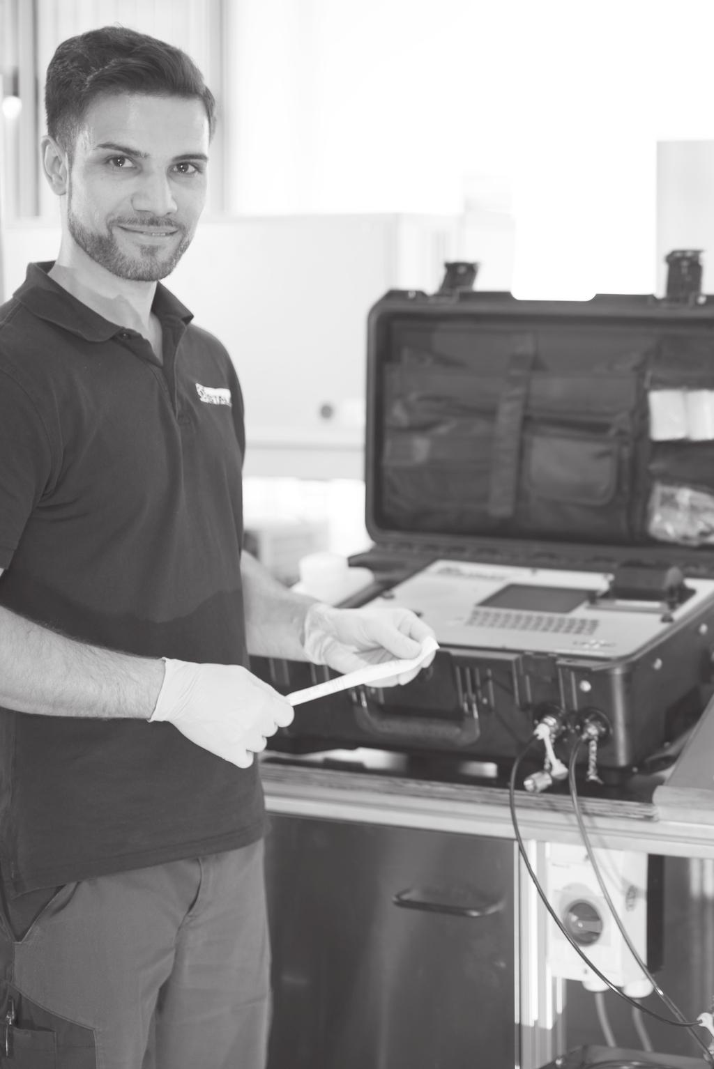
78
79 Appendix Product-Specific Abbreviations 80 Global Contact Directory Catalogue 8 Edition 10/
80 Appendix Product-Specific Abbreviations Abbreviation Product Category Product Description Page ottle-sampler-laspac-ii Oil Analysis Equipment ottle Sampler Unit 66 Display-LPM-II-Remote Oil Analysis Equipment Particle Monitor 71 Interface-LPM-II-US/ETH Oil Analysis Equipment Particle Monitor Interface 71 LasPaC-II-M Oil Analysis Equipment Laser Particle Counter (Mobile) 64 LasPaC-II-P Oil Analysis Equipment Laser Particle Counter (Portable) 62 LPM-II Oil Analysis Equipment Particle Monitor 70 LPM-II-... -CX Oil Analysis Equipment Particle Monitor (ATEX) 73 LPM-II-DAV Oil Analysis Equipment Flow Control Valve 72 OCS Oil Analysis Equipment Oil Condition Sensor 76 PPC-04/06/08-plus Hydraulic Testers Complete Systems 46 PPC-04/12-P Hydraulic Testers Pressure Sensors 34 PPC-04/12-PT Hydraulic Testers Pressure / Temperature Sensors 38 PPC-04/12-SDS-CA Hydraulic Testers Rotational Speed Sensor 42 PPC-04/12-SFM Hydraulic Testers Flow Turbine 40 PPC-04/12-T Hydraulic Testers Temperature Sensors 36 PPC-04-CAN-SET Hydraulic Testers Complete Systems 47 PPC-04-plus Hydraulic Testers Hydraulic Testers 28 PPC-04-plus-CAN Hydraulic Testers Hydraulic Testers 28 PPC-06/08-plus Hydraulic Testers Hydraulic Testers 29 PPC-CAN-FR Hydraulic Testers CAN Frequency Converter 45 PPC-CAN-P Hydraulic Testers Pressure Sensors 35 PPC-CAN-PT Hydraulic Testers Pressure / Temperature Sensors 39 PPC-CAN-SFM Hydraulic Testers Flow Turbine 41 PPC-CAN-T Hydraulic Testers Temperature Sensors 37 PPC-Pad Hydraulic Testers Hydraulic Testers 30 PPC-Pad-SET Hydraulic Testers Complete Systems 48 PT-RF Hydraulic Testers Pressure Transmitter 52 PT-RF-SET Hydraulic Testers Pressure Transmitter (Complete Systems) 54 Reader-PT-RF Hydraulic Testers Pressure Transmitter Reader 53 SDM Hydraulic Testers Flow Indicators 56 SDMKR Hydraulic Testers Flow Indicators 56 Sensorconverter-PPC Hydraulic Testers Current / Voltage / Frequency Converter 43 SFSK-1 /-2 Oil Analysis Equipment Oil Sampling Kit 74 SM-20 / SM-15 Pressure Gauges Analogue Pressure Test Kit 18 SM-DIGI Pressure Gauges Digital Pressure Test Kit 21 SPG Pressure Gauges Analogue Pressure Gauge 16 SPG-DIGI Pressure Gauges Digital Pressure Gauge 20 SAA /SDAA Hydraulic Testers Accumulator Adaptor for Pressure Transmitter Catalogue 8 Edition 10/2017
81 Appendix Catalogue 8 Edition 10/


 23867 Suello (LC) Tel.")

82 Appendix Global Contact Directory STAUFF products and services are globally available through wholly-owned subsidiaries and a tight network of authorised distributors and representatives in all major industrial regions of the world. Contact information on this page may be subject to changes and additions over time. Frequently updated and complete contact information can always be found at Germany Walter Stauffenberg GmbH & Co. KG Im Ehrenfeld Werdohl Tel.: Fax: sales@stauff.com Neuenrade-Küntrop Logistics Centre Wasserburgstraße Neuenrade Plettenberg-Ohle Production Site Lennestraße Plettenberg Voswinkel GmbH Neugrünenthal Meinerzhagen Tel.: Fax: info@voswinkel.net Europe France Ireland Italy Poland STAUFF S.A.S. 230, Avenue du Grain d Or Z.I. de Vineuil - lois Sud Vineuil-cedex Tel.: Fax: direction@stauffsa.com STAUFF UK Ltd. lock, 9 Ferguson Drive Knockmore Hill Industrial Estate Lisburn, County Antrim, T28 2EX Tel.: Fax: sales@stauffireland.com STAUFF Italia s.r.l Via orima 21 (Frazione orima) Suello (LC) Tel.: Fax: sales@stauff.it STAUFF Polska Sp. z o.o. Miszewko 43 A anino Tel.: Fax: sales@stauff.pl Russian Federation United Kingdon STAUFF LLC uilding 1 19, Leninskaya Sloboda Moscow, Tel.: Fax: sales@stauff.ru STAUFF UK Ltd. 500, Carlisle Street East Off Downgate Drive Sheffield, S4 8S Tel.: Fax: sales@stauff.co.uk STAUFF UK Ltd. adentoy Avenue adentoy Industrial Estate Portlethen, Aberdeen, A12 4Y Tel.: Fax: sales@stauffscotland.co.uk STAUFF UK Ltd. Unit 9, Southampton Trade Park Third Avenue, Millbrook Southampton, SO15 0AD Tel: Fax: sales@stauffsouthampton.co.uk Further branch offices in Engels, Volzhskiy, Magnitogorsk, Nizhny Novgorod and St. Petersburg. North America Canada United States South America razil STAUFF Canada Ltd. 866 Milner Avenue Scarborough Ontario M1 5N7 Tel.: Fax: sales@stauffcanada.com STAUFF Corporation 7 Wm. Demarest Place Waldwick, New Jersey Tel.: Fax: sales@stauffusa.com STAUFF rasil Ltda. Avenida Gupê Galpão 2 - loco A arueri, São Paulo, CEP Tel.: Fax: stauff@stauffbrasil.com Further branch office in Canton, Michigan. 82 Catalogue 8 Edition 10/2017
Catalogue 6 STAUFF Valves
 Two-Way Ball Valves Multi-Way Ball Valves Flow Control and Check Valves Gauge Isolator Valves Catalogue 6 STAUFF Valves Germany Walter Stauffenberg GmbH & Co. KG Im Ehrenfeld 4 58791 Werdohl Tel.: +49
Product Overview STAUFF Diagtronics
 Pressure Gauges Hydraulic Testers Oil Analysis Equipment Product Overview STAUFF Diagtronics With measuring, testing, display and analysis devices and equipment from the STAUFF Diagtronics product range,
SAE Flanges. Gear Pump Flanges. Catalogue 3 STAUFF Flanges
 AE langes ear Pump langes Catalogue 3 TAU langes ermany Walter tauffenberg mbh & Co. K Im Ehrenfeld 4 5879 Werdohl Tel.: +49 2392 9 60 ax: +49 2392 9 6 60 E-Mail: sales@stauff.com www.stauff.com TAU products
SPG-DIGI. Operating Instruction. Please read carefully before use!
 WALTER STAUFFENBERG GMBH & CO.KG Im Ehrenfeld 4 D-58791 Werdohl Postfach 1745 D-58777 Werdohl Germany Tel.: +49 (0) 2392 / 916-0 Fax: +49 (0) 2392 / 2505 E-Mail: sales@stauff.com Internet: www.stauff.com
Catalogue 7 STAUFF Test
 est Couplings est daptors est Hoses and Connectors Catalogue 7 SUFF est Germany Walter Stauffenberg GmbH & Co. KG Im Ehrenfeld 4 58791 Werdohl el.: +49 2392 91 60 Fax: +49 2392 91 61 60 E-Mail: sales@stauff.com
Endless Opportunities. Pressure Transmitter and Reader. of the Series PT-RF. Pressure Transmitter and Reader. of the PT-RF Series
 Endless Opportunities of the Originating and located in Werdohl in the German Sauerland region, we have become an internationally leading developer, manufacturer and supplier of pipework equipment and
Catalogue 10 STAUFF Hydraulic Accessories
 Fluid Level and Temperature Indicators Tank Filler Breathers Giant and Desiccant Air Breathers Suction Strainers Diffusors Catalogue 10 STAUFF Hydraulic Accessories Germany Walter Stauffenberg GmbH & Co.
Portable pressure calibrator, Wally Box III Model CPH7600
 Calibration technology Portable pressure calibrator, Wally Box III Model CPH7600 WIKA data sheet CT 17.01 Applications Calibration service companies and service industry Measurement and control laboratories
JUMO dtrans p20. Process pressure transmitter. Type Brief description. Key features. Block diagram
 Data Sheet 403025 Page 1/10 JUMO dtrans p20 Process pressure transmitter Brief description The JUMO dtrans p20 pressure transmitter with HART interface combines maximum precision with easy operation. It
Fluid Technology Components for Mobile Construction Machinery
 Local Solutions For Individual Customers Worldwide STAUFF Clamps STAUFF Test Filtration Technology Diagtronics Hydraulic Accessories Valves Flanges Fluid Technology Components Product Overview Mobile Machines
Catalogue 7 STAUFF Test
 est Couplings est daptors est Hoses and Connectors Catalogue 7 SUFF est Introduction Introduction 4-11 est Couplings 12-53 est daptors 54-59 B est Hoses and Connectors 60-71 C echnical ppendix 72-77 D
Parker Hannifin GmbH & Co. KG Tube Fittings Division Europe Am Metallwerk 9, Bielefeld Phone Fax
 Parker Hannifin GmbH & Co. KG Tube Fittings Division Europe Am Metallwerk 9, 33659 Bielefeld Phone ++49-521-4048-0 Fax ++49-521-4048-4280 Operating Instruction ServiceJunior SensoControl Please read carefully
JUMO dtrans p20 DELTA
 Data Sheet 403022 Page 1/9 JUMO dtrans p20 DELTA Differential pressure transmitter Brief description The JUMO dtrans p20 DELTA differential pressure transmitter with HART interface combines maximum precision
DM01. Battery Powered Precision Digital Gauge. Stainless Steel Sensor. class 0.05
 Battery Powered Stainless Steel Sensor class 0.05 Nominal pressure from 0 00 mbar up to 0... 00 bar Special characteristics modular sensor concept data logger graphic display stainless steel housing Ø
Mobile Filtration Systems SMFS-P and SMFS-U
 SMFS-P-015 SMFS-U-030 SMFS-U-DL-015-G SMFS-U-060 SMFS-U-110 SMFS-U-CM-110 Mobile Filtration Systems SMFS-P and SMFS-U Introduction 2 Introduction STAUFF Filtration Technology offers a complete range of
DL 01. Battery Powered Precision Digital Gauge for Leak Testing. Stainless Steel Sensor. class 0.05
 DL 0 Battery Powered for Leak Testing Stainless Steel Sensor class 0.05 Nominal pressure from 0 00 mbar up to 0... 00 bar Special characteristics modular sensor concept data logger graphic display stainless
10 Pressure/temperature measurement SCPT analogue
 10 Pressure/temperature measurement SCPT analogue Pressure/temperature measurement SCPT analogue Robust stainless steel design Response times of 1 ms Capturing of pressure peaks Accuracy ±0.5 % Fast response
Electronic Pressure Switch EDS 3000
 Description: The EDS 3000 is a compact, electronic pressure switch with integral digital display. The unit can have one or two switching outputs, and there is the option of an additional analogue output
Differential Pressure and Flow meters Accessories for the Media Series
 Differential Pressure and Flow meters Accessories for the Media Series 7 8 9 10 11 6 12 Media 5 Media 6 Media 05 1 5 2 4 Media 4 3 Selection and application These accessories upgrade the devices of the
Magnetic-inductive flow meter EPS / UMF2. Technical data sheet
 Magnetic-inductive flow meter EPS / UMF2 Technical data sheet high accuracy: 0.3 % of actual maintenance-free no pressure drop numerous lining materials numerous electrode materials low-cost grounding
Pressure Transmitters
 Transmitters Wetted parts are all made of stainless steel for high resistance to chemicals Stainless steel diaphragm welded with casing No seals and thus low leakage rate even with difficult gases High
Hydraulic Deadweight Tester Model CPB5800
 Calibration technology Hydraulic Deadweight Tester Model CPB5800 Applications Primary standard for ranges up to 20,000 psi hydraulic Pressure reference / calibration standard used in production and calibration
Low voltage AC drives. ABB micro drives ACS to 3 hp/0.18 to 2.2 kw Catalog
 Low voltage AC drives ABB micro drives ACS55 0.25 to 3 hp/0.18 to 2.2 kw Catalog ACS55 IP20 Overview ACS55 micro drives are designed for use in a wide variety of simple machinery applications where only
STAUFF Test. Test Couplings. Test Adaptors. Test Hoses and Connectors. Product Overview
 Test Adaptors Test Hoses and Connectors Product Overview STAUFF Test Test couplings from the STAUFF Test product range are already planned in suitable positions in the hydraulic system during the design
Magnetic-inductive flow meter for hazardous areas
 Magnetic-inductive flow meter for hazardous areas Technical Datasheet EPX / UMF3 high accuracy: 0.3 % of actual maintenance-free no pressure drop numerous lining materials numerous electrode materials
The right choice for your application. Pressure sensors from ifm.
 The right choice for your application. Pressure sensors from ifm. Process sensors www.ifm.com/gb/pressure Systems for pressure monitoring. The optimum solution for every requirement. Pressure sensors with
Types E2 and D2. Types Q and L. Including products with: Digital Precision Pressure Gauges
 JJ Types E-Ex and D-Ex JJ Types E2 and D2 JJ Type J JJ Type P JJ Types Q and L Including products with: Digital Precision Pressure Gauges DS_Digital_Precision_Pressure_gauges 01/2016 Digital precision
Pressure/temperature/RPM measurement
 Pressure/temperature/RPM measurement Pressure/temperature/RPM measurement Various sensors are available depending on the measurement requirements. Pressure sensors, type SCP Robust stainless steel design
JUMO DELOS SI. Precision pressure transmitter with switching contacts and display. Application. Brief description. Key features.
 Data sheet 405052 Page 1/10 JUMO DELOS SI Precision pressure transmitter with switching contacts and display Application Food & pharma CIP/SIP systems Machine and system construction Air conditioning and
Solid State Electronic Pressure Switch with Integral LED Display Model PSD-10
 Solid State Electronic Pressure Switch with Integral LED Display Model PSD-10 Electronic Pressure Measurement WIKA Datasheet PSD-10 Applications Hydraulics and pneumatics Filter monitoring Pump control
Unidrive M600 High performance drive for induction and sensorless permanent magnet motors
 Unidrive M600 High performance drive for induction and sensorless permanent magnet motors 0.75 kw - 2.8 MW Heavy Duty (1.0 hp - 4,200 hp) 200 V 400 V 575 V 690 V Unidrive M600 features Easy click-in keypad
JUMO MIDAS S05 Pressure transmitter Type
 Data Sheet 40.00 Page /8 JUMO MIDAS S05 Pressure transmitter Type 4000 Brief description The JUMO MIDAS S05 pressure transmitter is available with both relative pressure and absolute pressure measurement
2018 High Performance Check Valves for liquid and gaseous media
 2018 High Performance Check Valves for liquid and gaseous media Check valves Catalogue 45 Date: 04/2018 WEH - We Engineer Hightech All rights reserved, WEH GmbH 2018. Unauthorized copies are strictly forbidden
Miniature resistance thermometer For sanitary applications Model TR21-A, with flange connection
 Electrical temperature measurement Miniature resistance thermometer For sanitary applications Model TR21-A, with flange connection WIKA data sheet TE 60.26 Applications Sanitary applications Food and beverage
Mechanical pressure gauges
 J Bourdon tube pressure gauges J Differential pressure gauges J Diaphragm pressure gauges J capsule element pressure gauges Mechanical pressure gauges J Contains products with: DS_Mechanical_pressure_gauges
flowtronic Sensor Series S8005 flowtronic Sensor Series S8005 Product Information Version GREGORY Technology GmbH
 Product Information Version 11.04.2016 GREGORY Technology GmbH www.flowtronic.de Introduction The flowtronic sensors are developed for fuel consumption measurement of internal combustion engines. Today
SAE J1939 CAN compatible sensors for hydraulic system monitoring of flow, pressure and temperature on pumps, valves and hydrostatic transmissions
 SAE J99 CAN compatible sensors for hydraulic system monitoring of flow, pressure and temperature on pumps, valves and hydrostatic transmissions Milwaukee, WI, USA Tel: + () 769-600 sales-us@webtec.com
JUMO dtrans p20. Process pressure transmitter. Brief description. Special features. Block diagram. Approvals/approval marks (see "Technical data")
") Page 1/15 JUMO dtrans p20 Process pressure transmitter Brief description The device with the HART interface combines maximum precision with simple operation. It is used to measure the system pressure of
Page 1/15 JUMO dtrans p20 Process pressure transmitter Brief description The device with the HART interface combines maximum precision with simple operation. It is used to measure the system pressure of
SITRANS P measuring instruments for pressure
 Overview Application The pressure transmitter is designed for the special requirements of the food, pharmaceutical and biotechnology industries. The use of high-grade materials guarantees compliance with
US-S/FFL. Ultrasonic energy meters. Function. Flexible design. Connection. Mounting. High reliability
 Revision 2017-08-15 Ultrasonic energy meters Flanged ultrasonic energy meters, intended for heating or cooling. Size DN25 DN100 Nominal flow 3.5 60 m³/h For horizontal or vertical mounting No data loss
Technical Documentation
 Technical Documentation Product manual Holding brake controller Document: 0198441113316 Edition: V1.00, 03.2006 Important information The drive systems described here are products for general use that
JUMO thermocor. Portable measuring system for AMS2750 and CQI-9. Brief description. Block diagram. Special features. JUMO thermocor.
 sales@jumo.co.uk info.us@jumo.net Page 1/8 JUMO thermocor Portable measuring system for AMS2750 and CQI-9 Brief description The JUMO thermocor is a high-precision documenting test device with 12 analog
This section covers the comprehensive range of Torque Calibration equipment manufactured by Gedore Torque.
 Torque Calibration Introduction This section covers the comprehensive range of Torque Calibration equipment manufactured by Gedore Torque. Torque calibration equipment is used for the testing, calibration
Pressure balance Differential pressure version Model CPB5600DP
 Calibration technology Pressure balance Differential version Model CPB5600DP WIKA data sheet CT 31.56 for further approvals see page 7 Applications Primary standard for the calibration of differential
Heating chamber with mechanical convection
 FED series 720 Drying ovens / Heating ovens Heating chamber with mechanical convection The multi-talented BINDER heating chamber of the FED series provides almost unlimited capacity and is particularly
SUCO Product Overview
 SUCO Product Overview Pressure Monitoring & an overview Mechanical Pressure Switches Electronic Pressure Sensors www.suco.de Mechanical Pressure Switches Pressure Switches with integrated connectors NO
Differential pressure transmitter PASCAL Ci4 Delta P
 Differential pressure transmitter PASCAL Ci4 Delta P for general application, Type Series CI4300 Features Differential pressure transmitter with metallic diaphragm High-resolution graphic display with
Spin-on filter according to Bosch Rexroth standard: Type 50 SL 30 to 80D. Features. Contents. RE Edition:
 Spin-on filter according to Bosch Rexroth standard: Type 50 SL 30 to 80D RE 51476 Edition: 2015-06 Nominal sizes: 30 to 80D Connection up to G1; SAE 10 56558_d Features Spin-on filters are used in hydraulic
Resistance thermometer with digital display Model TR75, battery operation
 Electrical temperature measurement Resistance thermometer with digital display Model TR75, battery operation WIKA data sheet TE 60.75 Applications DiwiTherm Machine building, plant and vessel construction
GEMÜ 549 esydrive Motorized globe valve
 esydrive Motorized globe valve Features Linear or modified equal-percentage control characteristics High flow rates Force and speed are variably adjustable Extensive diagnostic facilities Operable via
Heating chamber with mechanical convection
 FED series 53 Drying ovens / Heating ovens Heating chamber with mechanical convection The multi-talented BINDER heating chamber of the FED series provides almost unlimited capacity and is particularly
Products Solutions Services. Customized Pressure Sensors and Components Made by Endress+Hauser
 Products Solutions Services Customized Pressure Sensors and Components Made by Endress+Hauser 2 Customized Pressure Sensors and Components High quality for your application and products The development
Electronic flow switch With display, for liquid media Model FSD-3
 Flow Electronic flow switch With display, for liquid media Model FSD-3 WIKA data sheet FL 80.01 Applications Control of cooling lubricant systems Monitoring of cooling circuits Control of filter units
JUMO thermocor. Portable measuring system for AMS2750 and CQI-9. Brief description. Block diagram. Special features. JUMO thermocor.
 Page 1/8 JUMO thermocor Portable measuring system for AMS2750 and CQI-9 Brief description The JUMO thermocor is a high-precision documenting test device with 12 analog inputs for thermocouples. The use
Spin-on elements. Type 80, 81 and 82. Contents. Features. RE Edition:
 Spin-on elements Type 80, 81 and 82 RE 51478 Edition: 2015-06 Sizes according to according to Bosch Rexroth standard: 30 to 130 Pressure differential resistance up to 5 bar [72.5 psi] Filter rating: 1
DCT 533. Industrial Pressure Transmitter with IO-Link Interface. Stainless Steel Sensor
 DCT 5 Industrial Pressure Transmitter with IO-Link Interface Stainless Steel Sensor accuracy according to IEC 60770: standart: ± 0.5 % FSO sption: ± 0.5 % FSO Nominal pressure from 0... 00 mbar up to 0...
Differential pressure transmitter PASCAL Ci4 Delta P
 Differential pressure transmitter PASCAL Ci4 Delta P for diaphragm seal operation, Type series CI4330 Features Application area General process engineering Chemical and petrochemical industry General process
DIGI-TEL THERMOMETERS
 TEL-TRU MANUFACTURING COMPANY DIGI-TEL THERMOMETERS www.teltru.com ELECTRONIC DIGITAL THERMOMETERS Tel-Tru s DIGI-TEL Thermometers combine the easy, quick visual reference feature of a local indicator
SUCO Product Overview
 SUCO Product Overview Pressure Monitoring & an overview www.suco-tech.com Pressure Switches with integrated connectors NO / NC / Changeover IP67 (up to IP6K9K) Robust, compact design Various connector
P r e s s u r e i S w i t c h e s V a c u u m i S w i t c h e s PressureiTransmitters
 P r e s s u r e i M o n i t o r i n g P r e s s u r e i S w i t c h e s V a c u u m i S w i t c h e s PressureiTransmitters TRADITION AND INNOVATION From a mechanical workshop to an international industrial
INSTRUMENTATION & CONTROL
 Irrigation Controller.................... 172 Window Controller.................... 174 Water Meter Controller.................. 176 Digital Level Switch.................... 177 Filtration Controller Set..................
CATALOG. ABB micro drives ACS55, 0.18 to 2.2 kw
 CATALOG ABB micro drives ACS55, 0.18 to 2.2 kw 2 ABB MICRO DRIVES, ACS55, 0.18 TO 2.2 KW/0.25 TO 3 HP Ease of integration. ACS55 drives. 3 Table of contents 004 ABB micro drives, ACS55 005 Easily integrated
SensoControl Diagnostic Equipment
 SensoControl Diagnostic Equipment Together, We Can Measure and Record Critical Data A Wise Investment An ounce of prevention Diagnosing a problem before it occurs should be your primary objective. Whether
VALVE CONTROLLERS Controllers for Dust Extr 2010 / 2011 action Technology
 VALVE CONTROLLERS Controllers for Dust Extraction 2010 Technology / 2011 Valve controllers for all cases HESCH has the skills and technology to tackle any control task for dedusting of filter and dust
Industrial Diesel Generator Set KD2250-F 50 Hz Fuel Consumption Optimized
 RATINGS 400 V - 50 Hz Standby kva 2250 KWe 1800 Prime kva 2045 KWe 1636 Benefits & features premium quality provides one source responsibility for the generating system and accessories The generator set,
GEMÜ 539 esydrive Motorized globe valve
 esydrive Motorized globe valve Features Linear or modified equal-percentage control characteristics High flow rates Force and speed are variably adjustable Extensive diagnostic facilities Operable via
Pipe surface resistance thermometer, for clamping Model TR57-M, miniature design
 Electrical temperature measurement Pipe surface resistance thermometer, for clamping Model TR57-M, miniature design WIKA data sheet TE 60.57 Applications Sanitary applications Food and beverage industry
Second Life. First Choice.
 Second Life. First Choice. Turbocharger overhaul The right turn for a sustainable business With improved balancing quality and profitability in the overhaul of turbochargers RT 1061-1e TURBOCHARGER OVERHAUL
WSTH/WPTH. Woltmann type combined energy meter. Measuring distance. Function. Connection. High reliability. Mounting.
 Woltmann type combined energy meter Flanged Woltmann flow meters for large nominal flows, intended for flow measurements in large plants, such as those found in district heating systems. Size DN50 DN300
Pressure transmitter PASCAL CV4
 Pressure transmitter PASCAL CV4 with threaded connection, Type series CV4100 Features Application area Pharmaceutical industry Food industry Biotechnology General process technology Compact case of stainless
Industrial Diesel Generator Set KD3300-F 50 Hz Fuel Consumption Optimized
 RATINGS 400 V - 50 Hz Standby kva 3300 KWe 2640 Prime kva 3000 KWe 2400 Benefits & features premium quality provides one source responsibility for the generating system and accessories The generator set,
Heating chamber with mechanical convection
 FED series 240 Drying ovens / Heating ovens Heating chamber with mechanical convection The multi-talented BINDER heating chamber of the FED series provides almost unlimited capacity and is particularly
ETP80. Electronic Transmitter for Pressure, Differential Pressure and Level
 ETP80 Electronic Transmitter for Pressure, Differential Pressure and Level The ETP80 is a series of pressure transmitters with a wide range of s to suit most applications. The transmitters can measure
Reliable and powerful starting for diesel engines and generators
 When Power is Critical EN-1834-1 EN-1834-2 Reliable and powerful starting for diesel engines and generators HYDRAULIC STARTING SYSTEMS For diesel engines up to 80 litres IPU s hydraulic starting systems
Technical Information Cleanfit Control CYC25
 TI01231C/07/EN/04.16 71326840 Products Solutions Services Technical Information Cleanfit Control CYC25 Cleaning unit for retractable assemblies in conjunction with Chemoclean Plus Application Cleanfit
High-Tech Waterjet Cutting
 6,200 bar High-Pressure Innovations STREAMLINE PRO-I ultra high-pressure pumps PRO series cutting heads AMS PRO abrasive management system PSC PRO installation parts High-Tech Waterjet Cutting About KMT
More Precision. mainsensor Magneto-inductive displacement sensor
 More Precision mainsensor Magneto-inductive displacement sensor mainsensor Magneto-inductive sensors for non-contact linear displacement measurement Measuring principle mainsensor is based on an innovative
Customised drive solutions
 Customised drive solutions Electric motors & systems Drive components Services Introduction 03 Halm quality drive technology Over 50 years of experience in developing electric motors with asynchronous
Dead-weight tester in compact design Model CPB3800
 Calibration Dead-weight tester in compact design Model CPB3800 WIKA data sheet CT 31.06 for further approvals see page 9 Applications Primary standard for calibrating the scale in a hydraulic range up
Industrial Diesel Generator Set KD3500-F 50 Hz Fuel Consumption Optimized
 RATINGS 400 V - 50 Hz Standby kva 3500 KWe 2800 Prime kva 3182 KWe 2546 Benefits & features premium quality provides one source responsibility for the generating system and accessories The generator set,
Motor-pump group. Features. Table of contents RE 51171/ Type ABAPG and ABHPG
 Motor-pump group RE 51171/07.12 1/16 Type ABAPG and ABHPG with pump type: PV7 Electric motor frame size 90S to 250M max. pressure up to 160 bar max. flow up to 162.5 l/min H7896+7897_d Table of contents
Resistance thermometer For sanitary applications Model TR22-B, for orbital welding
 Electrical temperature measurement Resistance thermometer For sanitary applications Model TR22-B, for orbital welding WIKA data sheet TE 60.23 for further approvals see page 11 Applications Sanitary applications
2-Color Display High-Precision Digital Pressure Switch
 2-Color Display High-Precision Digital Pressure Switch Settings can be copied to up to 1 slave sensors at once. The settings of the master sensor can be copied to the slave sensors. Reduced setting efforts
Heating chamber with mechanical convection
 FED series 53 Drying ovens / Heating ovens Heating chamber with mechanical convection The multi-talented BINDER heating chamber of the FED series provides almost unlimited capacity and is particularly
SATRON VTe pressure transmitter
 SATRON VTe pressure transmitter belongs to the series V-transmitters which will have both analog and smart properties. SATRON VTe is used for 0-4 kpa...0-00 MPa ranges. The transmitter communicates in
Technical Information Liquiline System CAT810
 TI01138C/07/EN/02.16 71341422 Products Solutions Services Technical Information Control of sample preparation by the Liquiline System CA80 or a time control system Automatic sample preparation system for
Quality and Service worldwide. Hydraulic Accessories Flow Indicators
 Quality and Service worldwide Hydraulic Accessories Flow Indicators Distributor Walter Stauffenberg GmbH & Co. KG P.O.Box 1745 D-58777 Werdohl Im Ehrenfeld 4 D-58791 Werdohl Tel. : + 49 (0) 2392 916-0
Micro Motion 7827 Digital Viscosity Meter
 Product Data Sheet PS-001217, Rev. C April 2013 Micro Motion 7827 Digital Viscosity Meter Micro Motion viscosity meters are built to tackle the most demanding process and control applications. Rugged and
DMP 331. Industrial Pressure Transmitter for Low Pressure. Stainless Steel Sensor
 DMP Industrial Pressure Transmitter for Low Pressure Stainless Steel Sensor accuracy according to IEC 60770: standard: 0.5 % FSO option: 0.5 / 0. % FSO Nominal pressure from 0... 00 mbar up to 0... 40
Drilling Rig LB LB
 Drilling Rig LB 16-18 EN LB 1.6 Concept and characteristics Leader top for Kelly rope Leader top for auxiliary rope Kelly rope Kelly Rotary Inclination device Special "Low Head" Auxiliary winch Standard
P500 Pressure Sensor. Description. Features. Applications MAIN FEATURES
 P500 Pressure Sensor Description The P500 incorporates Kavlico s 4th generation ceramic capacitive sense element with the latest state of the art proprietary ASIC. Available in brass or stainless steel
Intelligent Positioner
 Intelligent Positioner Construction The GEMÜ 1 µpos is a digital electro-pneumatic positioner for process valve control. Designed for simple, safe and quick use with valves with strokes < mm. The positioner,
GREASE CONTROL GUNS GREASE CONTROL GUNS Grease control gun Grease control gun with rigid stem and 3 jaw connector ( ).
.") MEASURE AND CONTROL GREASE CONTROL GUNS AND ACCESSORIES GREASE METERS OIL CONTROL GUNS AND ACCESSORIES OIL METERS OIL METER ACCESSORIES FLUID CONTROL GUNS FLUID METERS HIGH FLOW IN LINE METERS ADVANCED
MEASURE AND CONTROL GREASE CONTROL GUNS AND ACCESSORIES GREASE METERS OIL CONTROL GUNS AND ACCESSORIES OIL METERS OIL METER ACCESSORIES FLUID CONTROL GUNS FLUID METERS HIGH FLOW IN LINE METERS ADVANCED
FEATURES AND BENEFITS
 DESCRIPTION Honeywell Zephyr Digital Airflow Sensors: HAF Series-High Accuracy, provide a digital interface for reading airflow over the specified full scale flow span and temperature range. Their thermally
Differential Pressure Gauges Cryo Gauge Model , Cu-alloy Model , Stainless Steel Series
 Differential Pressure Gauges Cryo Gauge Model 712.15.160, Cu-alloy Model 732.15.160, Stainless Steel Series Mechanical Pressure Measurement WIKA Data Sheet PM 07.30 Applications Level measurement in closed
Industrial communication AS-Interface instead of complex wiring
 Industrial communication www.ifm.com/gb/as-i instead of complex wiring controllers / gateways Safe, easy, cost-optimised! I/O modules expansion power supplies / earth fault monitors AirBoxes for pneumatics
Inductive conductivity meter
 Inductive conductivity meter CIP version Type 8228 can be combined with... Standard version Perfect for concentrated liquids and wide conductivity range Pre-parameterized versions available for direct
WE CREATE CONNECTIONS
 WE CREATE CONNECTIONS Introduction THERE ARE MORE THAN A FEW GOOD REASONS We are a renowned German provider of fluid technology systems and components with a primary focus on hydraulics and pneumatics.
Resistance thermometer with digital indicator Model TR75, battery operation
 Electrical temperature measurement Resistance thermometer with digital indicator Model TR75, battery operation WIKA data sheet TE 60.75 Applications DiwiTherm Machine building, plant and vessel construction
OPTISWITCH 6500 C Technical Datasheet
 OPTISWITCH 6500 C Technical Datasheet Switch for level detection and dry-run protection Optimised sensor geometry, easy to clean Measures products with dielectric constant > 1.5 Maintenance-free KROHNE