SURE TRIP SLT-201 SECONDARY TEST SET
|
|
|
- Claire Newman
- 6 years ago
- Views:
Transcription
1 1 SURE TRIP SLT-201 SECONDARY TEST SET SURE TRIP, INC 703-A CONCORD ROAD ALBEMARLE, NORTH CAROLINA TOLL FREE: (877) (800) FAX: (905) (704) E MAIL: SURETRIP@suretrip.com
2 2 SLT-201 SECONDARY TEST SET The SURE TRIP SLT-201 Secondary Test Set has been designed to perform full function testing of the RMS-2007AF, RMS-2002, RMS-85, WESTRIP RMS-2000, AMPTECTOR, and ITEKTOR Logic controllers. It allows the user to check the time current characteristics of the logic programmer at an infinite number of points along its curves, test the programmer diagnostic circuitry, and flux shifter operation. The test set is a rugged, lightweight, portable device designed specifically with the service man in mind. The following are some simple precautions that should be observed when performing a secondary test on any logic controller. * The Test Set operates, at full load, at more than 60 amps and is designed to handle current amplitudes according to the Long Time trip curves. Prolonged or repetitive testing at higher current settings will cause internal damage to the Test Set and Logic. * Holding the CALIBRATE switch for more than 10 to 15 seconds at a time may cause overheating and/or damage to the Test Set and Logic. * Use the STOP whenever a trip occurs and the Test Set does not cut off. LEGEND TO PICTURE 1 1> POWER CORD 2> FUSE 3> POWER 4> TRIP TIMER 5> AMMETER 6> PHASE SELECTOR 7> ACTUATOR 8> TIMER 9> RESET 10> PICK-UP 11> TEST 12> CALIBRATE 13> RANGE 14> VARIAC 15> STOP 16> TEST/RESET 17> INST 18> SHORT DELAY 19> LOGIC SELECTOR 20> GROUND FAULT 21> EXTERNAL AMMETER 22> RMS 2007AF INTERFACE CABLE 23> OPTIONAL AMPTECTOR & ITEKTOR INTERFACE CABLE 1> POWER CORD Receptacle for inserting modular power cord supplied with unit 2> FUSE Replace with 4A fuse only. 3> POWER Switch turns power on and off to the test set. The red lamp indicates when power is on. Lamp will not light if Fuse has failed. 4> TRIP TIMER Meter shows the elapsed time between the start of the Test and the trip pulse from the logic. 5> AMMETER Meter shows the level of current flowing to the logic from the test set. The reading updates about 3 times per second. 6> PHASE SELECTOR 4-Position switch that simulates the three phase ( A, B, C ) currents for testing of the logic inputs. The N setting is for testing of the GROUND FAULT on the AMPTECTOR or ITEKTOR logic. 7> ACTUATOR Binding post that allows an external actuator to be tested with the logic without having to wire directly to the logic. 8> TIMER Switch to turn the TRIP TIMER indication ON or OFF.
3 9> RESET Green indication for the RESET function of the test set. 3 10> PICK-UP Yellow indication that shows PICK-UP for the AMPTECTOR or ITECKTOR logic. 11> TEST Red indication for the TEST function of the test set. 12> CALIBRATE Switch that allows the test current to be set at higher levels. It turns on the output current and prevents the test set from tripping. 13> RANGE LO limits the output current to about 7.5 Amps. HI is not limited and will exceed 60A when testing a logic. Care should be taken to start all tests at the lower setting so as not to damage the logic control. The N setting of the PHASE SELECTOR switch works with the LO setting only. 14> VARIAC Provides for accurate control of the output current. Levels are determined by the setting on the RANGE switch. 15> STOP Switch stops all tests that are in progress. 16> TEST/RESET Switch to the TEST position to begin the test. The RESET position to reset the test set after a trip. The test set must be RESET after turning the test set ON and prior to running any test. 17> INST Disables the INSTANTANEOUS function on the AMPTECTOR and ITECKTOR logic. 18> SHORT DELAY Defeats the SHORT DELAY function on the AMPTECTOR and ITECKTOR logic. 19> LOGIC SELECTOR Used to select the type of logic being tested. 20> GROUND FAULT TEST position to test the GROUND FAULT portion of the SURETRIP RMS DEFEAT position to test the LONG TIME, SHORT TIME, and INSTANTANEOUS functions of the RMS-2007AF, RMS-2002, RMS-85, WESTRIP RMS > EXTERNAL AMMETER Binding posts that allows an external ammeter to be connected to the test set. Can be used to verify the AMMETER reading. A jumper must be placed between the posts if an external ammeter is not used. 22> SURETRIP RMS-2007AF INTERFACE CABLE(Not Pictured) Allows for the interface of the test set and the SURETRIP RMS-2007AF logic. 23>OPTIONAL AMPTECTOR & ITEKTOR INTERFACE CABLE(Not Pictured) Allows for the interface of the test set and the AMPTECTOR & ITEKTOR logic.
4 4 BASIC SETUP AND TEST PROCEDURE 1. Insert the AC cord into the test set and connect to a 120-volt outlet. 2. Select the correct interface for the type of logic being tested. Connect it to the test set by screwing the round connector plugs together. Plug the into the logic. 3. Turn on test set by placing the POWER switch to the ON position. 4. RESET the Test Set using the TEST/RESET switch. 5. If an external ammeter is not used, make certain that a jumper is placed between the EXTERNAL AMMETER binding posts. 6. Set VARIAC to 0 and RANGE to LO. *After testing a selected pick-up current or delay function, it is advised to return the VARIAC control to zero before proceeding to the next test. 7. To begin a test move the TEST/RESET switch to the TEST position. *When testing pick-up currents, start by selecting LO on the RANGE switch. With the VARIAC at zero turn clockwise until the unit trips or the pickup light turns on. If the logic controller does not trip at this setting, return the VARIAC to zero and select the HI position on the RANGE switch and proceed with the test. 8. Testing of each logic and function is described in more detail on the following pages. NOTE: When secondary testing with the Logic on the Breaker, it may not be possible to trip the Actuator and the Test Set Timer at the same time. To test the timing it may be necessary to remove the Actuator wiring. SAMPLE TEST CHART DATE: / / LOGIC SERIAL NUMBER: LONG TIME FUNCTION: SWITCH SETTING AMP TAP PICKUP CURRENT DELAY SETTING TEST CURRENT ELAPSED TIME A B C SHORT TIME FUNCTION: SWITCH SETTING AMP TAP PICKUP CURRENT DELAY SETTING TEST CURRENT ELAPSED TIME A B C INSTANTANEOUS FUNCTION: SWITCH SETTING AMP TAP PICKUP CURRENT TEST CURRENT ELAPSED TIME A B C ARC FLASH FUNCTION: SWITCH SETTING AMP TAP PICKUP CURRENT TEST CURRENT GROUND FAULT FUNCTION: SWITCH SETTING ELAPSED TIME A B C PICKUP CURRENT DELAY SETTING TEST CURRENT ELAPSED TIME A B C

5 5 2. FUSE 3. POWER 1. POWER CORD 6. PHASE SELECTOR 4. TRIP TIMER 7. ACTUATOR 8. TIMER 12. CALIBRATE 13. RANGE 17. INST 18. SHORT DELAY 9. RESET 11. TEST 10. PICK-UP 15. STOP 5. AMMETER 16. TEST/RESET 14. VARIAC 20. GROUND FAULT 21. EXTERNAL AMMETER 19. LOGIC SELECTOR TEST PROCEDURE FOR THE SURETRIP RMS-2007AF LOGIC 1. Using the RMS-2007AF Interface Cable, connect to the test set wiring harness to the logic box to be tested. 2. Verify the VARIAC is set to zero, RANGE is on LO, then switch POWER ON. 3. Switch the LOGIC SELECTOR to RMS-2007AF, etc. 4. RESET the test set. 5. When testing the LSI logic the GROUND FAULT switch must be set to DEFEAT. The LSIG logic can also be tested on this setting except for GROUND function. Set this switch to the TEST position to test the GROUND function. 6. After testing a selected pick-up current or delay function, it is advised that the VARIAC be returned to zero before proceeding to the next test. 7. When testing pick-up currents, start by selecting the LO RANGE. With the VARIAC at zero, turn clockwise until the unit trips or the pick-up light on the logic turns on. If the logic controller does not trip at this setting, return the VARIAC to zero and select HI RANGE and proceed with the test. 8. Testing of each function is described in more detail on the following pages. The Sample Test Chart on page 4 gives a basic layout for recording the results of the test performed on any Logic Control. The form can be used when testing on secondary or primary.
6 LONG TIME FUNCTION TESTING PICK-UP TEST 1. Select the Phase to be tested. Make certain all other functions are adjusted so as not to interfere with the selected test. 2. Set the LONG TIME Delay switch to 2 and the LONG TIME Pick up switch to the test point. 3. Start the Test Set and slowly increase the VARIAC from 0 until the PICK-UP LED on the logic turns on. The PICK-UP Light on the Test Set does not function with the WESTRIP RMS Record the AMMETER reading just as the pick-up LED lights. Compare the reading to that of Chart 2A. The reading should be within +/- 10% of the stated value. 5. Return VARIAC control to 0. Repeat for other phases or pick-up settings if desired. LONG TIME DELAY 1. Select the Phase to be tested. Make certain all other functions are adjusted so as not to interfere with the selected test. 2. Set the LONG TIME Delay switch to the desired setting; 2, 3, 4, 5, 7, 10, 12, 15, 20, or 24. These settings are referenced to a current level equal to 600% of the LONG TIME Pick-Up. Actual delays can vary in accordance with the Time vs. Current Characteristic curves. If a current level of 200% or 300% is used, refer to the table below for the corresponding timing range. 3. After the logic is adjusted, set the test current to the desired level, i.e. 300% of the long time pick-up switch setting. STOP the test and RESET the test set. 4. Start, TEST, the test set and let run until the logic trips and the TRIP TIMER stops. The TRIP TIMER should indicate the elapsed time. Compare this time to that of the Chart 1A below or the trip curves. Repeat for other phases or switch settings if desired. 5. Return the VARIAC to 0. Chart 1A Test Current Level Long Time Delay 200% 300% 600% *Time in Seconds Low Side High Side Low Side High Side Low Side High Side Delay Setting 6 LONG TIME PICK UP Chart 2A L/T Pick-Up Amp Tap
7 SHORT TIME FUNCTION TESTING PICK-UP TEST 2. Set SHORT TIME Delay switch to.15 and adjust the SHORT TIME Pick up switch to the test point. 3. Start the Test Set and slowly increase the VARIAC from 0 until the logic trips. 4. Record the AMMETER reading at the moment the trip occurs. Compare the reading to the value found in Chart 2B. The reading should be within +/- 10% of the stated value. Repeat for other phases or pick-up settings if desired. 5. Return the VARIAC to 0. SHORT TIME DELAY 2. Set the SHORT TIME Delay switch to the desired setting;.1,.15,.2,.25,.3,.35,.4,.45,.5, or I 2 T. 3. Using the CALIBRATE switch set the test current to a level that is 150% of the SHORT TIME Pick-up current. Once the VARIAC is set, release the CALIBRATE switch. RESET the test set. When performing the test, the INSTANTANEOUS or ARC FLASH pick-up may interfere. If this occurs adjust the DEFEAT SELECTOR on the logic box to the INSTANTANEOUS setting and Jumper to external connector for the ARC FLASH Defeat to prevent tripping. 4. Start, TEST, the test set and let run until the logic trips and the TRIP TIMER stops. The TRIP TIMER should indicate the elapsed time. Compare this time to that of the Chart 1B below or the trip curves. Repeat for other phases or switch settings if desired. 5. Return the VARIAC to 0. Chart 1B Test Current Level Short Time Delay 150% *Time in milli-sec. Low Side High Side **I 2 T.58 Sec..90 Sec. **I 2 T Test Settings: AMP TAP = 1.0, SHORT TIME = 2, Test current = 15A. Delay Setting SHORT TIME PICK UP Chart 2B S/T Pick-up Amp Tap 7
8 INSTANTANEOUS FUNCTION TESTING PICK-UP TEST 2. Set INSTANTANEOUS Pick up switch to the test point. 3. Start the Test Set and slowly increase the VARIAC from 0 until the logic trips. 4. Record the AMPERE reading at the moment the trip occurs. Compare the reading to the value found in Chart 2C. The reading should be within +/- 10% of the stated value. Repeat for other phases or pick-up settings if desired. 5. Return the VARIAC to 0. INSTANTANEOUS DELAY 2. Using the CALIBRATE switch set the test current to a level that is 150% of the INSTANTANEOUS Pick-up current. Once the VARIAC is set, release the CALIBRATE switch. RESET the test set. 3. Start, TEST, the test set and let run until the logic trips and the TRIP TIMER stops. The TRIP TIMER should indicate the elapsed time. Compare this time to that of the Chart 1C below or the trip curves. Repeat for other phases or switch settings if desired. 4. Return the VARIAC to 0. Chart 1C Instantaneous Delay Set Secondary Current To 150% of Chart 2C No More Than.06 Sec INSTANTANEOUS PICK UP Chart 2C Inst. Pick-up Amp Tap 8
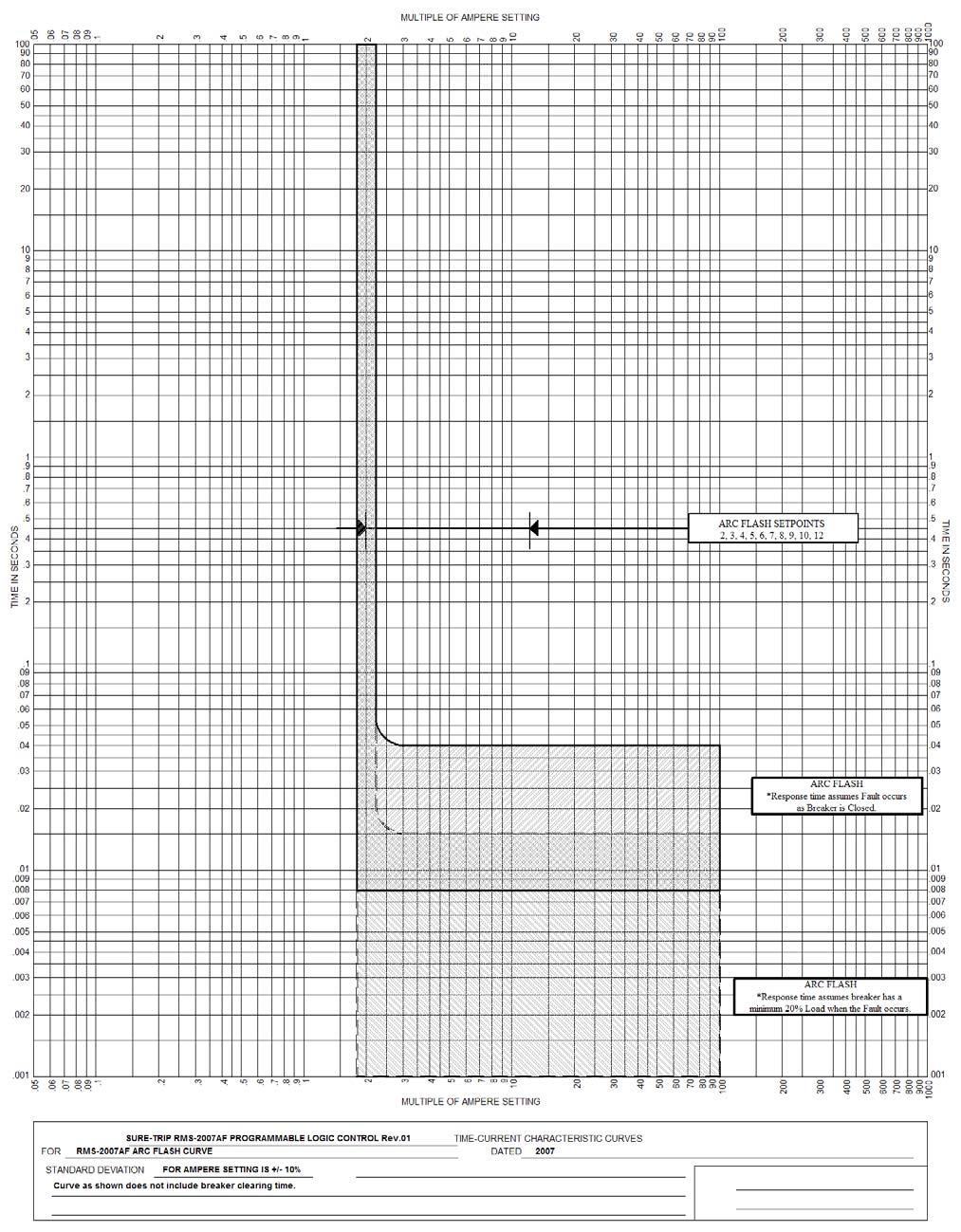
9 ARC FLASH FUNCTION TESTING PICK-UP TEST 2. Set ARC FLASH Pick up switch to the test point. 3. Start the Test Set and slowly increase the VARIAC from 0 until the logic trips. 4. Record the AMPERE reading at the moment the trip occurs. Compare the reading to the value found in Chart 2D. The reading should be within +/- 10% of the stated value. Repeat for other phases or pick-up settings if desired. 5. Return the VARIAC to 0. INSTANTANEOUS DELAY 2. Using the CALIBRATE switch set the test current to a level that is 150% of the ARC FLASH Pick-up current. Once the VARIAC is set, release the CALIBRATE switch. RESET the test set. 3. Start, TEST, the test set and let run until the logic trips and the TRIP TIMER stops. The TRIP TIMER should indicate the elapsed time. Compare this time to that of the Chart 1D below or the trip curves. Repeat for other phases or switch settings if desired. 4. Return the VARIAC to 0. Chart 1D Instantaneous Delay Set Secondary Current To 150% of Chart 2D No More Than.05 Sec ARC FLASH PICK UP Chart 2D Inst. Pick-up Amp Tap 9
10 GROUND FAULT FUNCTION TESTING PICK-UP 1. Set the GROUND FAULT switch to the TEST setting. 2. Select the Phase to be tested and set the LONG TIME Delay switch to 24. Make certain all other functions are 3. Set GROUND FAULT Delay switch to.15 and adjust the GROUND FAULT Pick up switch to the test point. 4. Start the Test Set and slowly increase the VARIAC from 0 until the logic trips. 5. Record the AMMETER reading at the moment the trip occurs. Compare the reading to the value found in Chart 2E. The reading should be within +/- 10% of the stated value. Repeat for other phases or pick-up settings if desired. 6. Return the VARIAC to 0. GROUND DELAY Verify that GROUND FAULT is set to TEST. 2. Set the GROUND FAULT Delay switch to the desired setting;.1,.15,.2,.25,.3,.35,.4,.45, or Using the CALIBRATE switch set the test current to a level that is 300% of the GROUND FAULT Pick-up current. Once the VARIAC is set, release the CALIBRATE switch. RESET the test set. 4. Start, TEST, the test set and let run until the logic trips and the TRIP TIMER stops. The TRIP TIMER should indicate the elapsed time. Compare this time to that of Chart 1E below or the trip curves. Repeat for other phases or switch settings if desired. 5. Return the VARIAC to Chart 1EE Test Current Level Ground Fault Delay 300% *Time in milli-sec Low Side High Side Delay Setting Chart 2E Ground Fault Pick-up Currents GROUND FAULT PICK UP Defeat No Trip NOTE GROUND FAULT Pick ups not affected by AMP TAP setting.

11 11
12 12
SURE-TRIP OEM RELACEMENT TRIP UNIT
 RMS CURRENT MEASUREMENT with SURE-TRIP OEM RELACEMENT TRIP UNIT Update Circuit Breaker Solid State Controls with SURE-TRIP LOGIC The SURE-TRIP Solid State Tripping Systems Have Been Designed, Tested And
SURE TRIP RETRO KITS
 RMS CURRENT MEASUREMENT with SURE TRIP RETRO KITS Circuit Breaker Solid State Controls with SURE TRIP LOGIC The Sure Trip Solid State Tripping Systems Have Been Designed, Tested And Produced To all Applicable
Table of Contents. For latest version, visit:
 Table of Contents 1.0 Introduction... 1.0 Overview... 1 3.0 Test Set Controls... 6 3.1 Power... 6 3. Time Display... 6 3.3 Timer Clear Push Button... 6 3.4 Start Push Button and LED... 6 3.5 Stop Push
Advanced Test Equipment Rentals ATEC (2832)
") Established 1981 Advanced Test Equipment Rentals www.atecorp.com 800-404-ATEC (2832) INSTRUCTIONS FOR MAGNUM DS TRIP UNIT TESTING USING TEST KIT SYLES 140D481G02R, 140D481G02RR, 140D481G03 AND 140D481G04
Established 1981 Advanced Test Equipment Rentals www.atecorp.com 800-404-ATEC (2832) INSTRUCTIONS FOR MAGNUM DS TRIP UNIT TESTING USING TEST KIT SYLES 140D481G02R, 140D481G02RR, 140D481G03 AND 140D481G04
PORTABLE CURRENT SOURCE FOR CIRCUIT BREAKER AND MOTOR OVERLOAD TESTING INSTRUCTION MANUAL PI-250B. Release 1.0 April 5, 2013
 PORTABLE CURRENT SOURCE FOR CIRCUIT BREAKER AND MOTOR OVERLOAD TESTING INSTRUCTION MANUAL PI-250B Release 1.0 April 5, 2013 Electrical Test Instruments, Inc. 1301 Avondale Road, Suite J New Windsor, MD
Cutler-Hammer. Installation Instructions for the Digitrip OPTIM Pole Trip Unit Installation and Operation with L-Frame Series C Circuit Breakers
 Cutler-Hammer Installation Instructions for the Digitrip OPTIM 550 3-Pole Trip Unit Installation and Operation with L-Frame Series C Circuit Breakers Table of Contents Description Page 1.0 General Information......................1
Phenix Technologies Inc. 75 Speicher Drive Accident, Maryland 21520
 USER S MANUAL PORTABLE HIGH CURRENT TEST SET MODEL NUMBER HC2 Version 4.0 Phenix Technologies Inc. 75 Speicher Drive Accident, Maryland 21520 Copyright Phenix Technologies, Inc. Rev 11/20/2014 nab TABLE
WESTINGHOUSE / CUTLER HAMMER DS POWER BREAKERS
 etc-12 e-series, direct replacement retrofit for WESTINGHOUSE / CUTLER HAMMER DS POWER BREAKERS Section 1 Installation Manual Contents Introduction. 1 Required Tools 2 Pre-Installation 2 Programmer Installation.
HT Dielectric Withstand Tester Volts AC Output 25mA Leakage Option
 HT-10000 Dielectric Withstand Tester 0-10000 Volts AC Output 25mA Leakage Option Instruction Manual COMPLIANCE WESTUSA Dear Customer: Congratulations! Compliance West USA is proud to present you with your
GENSET CONTROL MODULE A121A / A241A
 Technical Data Sheet GENSET CONTROL MODULE A121A / A241A Features: Models for both 12V and 24V systems. One model for both spark ignition and diesel engines. 4-alarm light outputs with lamp-test provisions.
PORTABLE POWER SUPPLY MODEL NUMBER VMS-1 VERSION 1.0
 PORTABLE POWER SUPPLY MODEL NUMBER VMS-1 VERSION 1.0 MM September 21, 2012 TABLE OF CONTENTS Section Number DANGER INTRODUCTION AND TECHNICAL SPECIFICATIONS 1 CONTROL AND METERING DESCRIPTION 2 OPERATION
SECTION MICROPROCESSOR TRIP UNITS FOR LV CIRCUIT BREAKERS. This section is organized as indicated below. Select desired Paragraphs.
 SECTION 16904 MICROPROCESSOR TRIP UNITS FOR LV CIRCUIT BREAKERS PART 2 PRODUCTS 01 MANUFACTURERS A. B. C. Eaton * * The listing of specific manufacturers above does not imply acceptance of their products
3 in 1 TRAIL CHARGER with LOCKOUT
 Owner s Manual P/N: 283821 500 3 in 1 TRAIL CHARGER with LOCKOUT 283821 01 Version 2.04 07/05/2011 Owners Manual Operation Installation Wiring Diagram Troubleshooting Parts Breakdown 1 GENERAL OPERATION
INSTRUCTION MANUAL MODEL CB-7120A CIRCUIT BREAKER
 INSTRUCTION MANUAL For MODEL CB-7120A CIRCUIT BREAKER TEST SET SERIAL NO. It is essential that this instruction book be read thoroughly before putting the equipment in service. APPRECIATION We are indebted
SELECT DIAGNOSTIC GUIDE. INST028 Doc 3.02
 SELECT DIAGNOSTIC GUIDE INST028 Doc 3.02 CONTENTS General Information...2 Select Call-Outs...3 Wire Diagram and Legend...4 Diagnostics...6 Excessive Voltage Drop Diagnostics...6 Static Diagnostics...7
Self-Testing Industrial Series
 Series: AS-I (Maint.-Free) Self-Testing Industrial Series Emergency Lighting Equipment Instructions for INSTALLATION OPERATION SERVICE SPECIFICATIONS 1300650 1300654 1300666 1300754 1300823 1300886 Hubbell
TRANSMISSION - NGC. Symptom: P0706-CHECK SHIFTER SIGNAL. When Monitored and Set Condition:
 Symptom: P0706-CHECK SHIFTER SIGNAL When Monitored and Set Condition: P0706-CHECK SHIFTER SIGNAL When Monitored: Continuously with the ignition on. Set Condition: After 3 occurrences in one ignition cycle
Valcom Failsafe Unit. 1620ESv2 SERIES. Operation and Maintenance Manual
 Valcom Failsafe Unit 1620ESv2 SERIES Operation and Maintenance Manual Table of Contents Section Title Page 1. - Introduction.. 2. - Unpacking the Failsafe unit. 3. - Installation 3.1 - Auto / Timed UPS
GENSET CONTROL MODULE LEVEL 1 A121CM / A241CM. Special logic to re-establish cranking following a false start.
 Technical Data Sheet GENSET CONTROL MODULE LEVEL 1 A121CM / A241CM Features: Models for both 12V and 24V systems. One model for both spark ignition and diesel engines. 5-alarm light outputs with lamp-test
HT Dielectric Withstand Tester Volts AC Output Volts DC Output COMPLIANCE WESTUSA. Instruction Manual
 HT-5000 Dielectric Withstand Tester 0-5000 Volts AC Output 0-7200 Volts DC Output Instruction Manual COMPLIANCE WESTUSA Dear Customer: Congratulations! Compliance West USA is proud to present you with
GRD502-B Flow Chart 02/05/09
 PINPOINT TEST A: NO PROVE OUT OF ANY LEDs prove out (all LED's light up) of the LED's when module power is applied or module "wakes up", indicates that: - the Guardian module does not have power. - the
www. ElectricalPartManuals. com Instructions for Field Testing of Ground Fault Systems Utilizing Cutler-Hammer Magnum DS Circuit Breakers
 Instructions for Field Testing of Ground Fault Systems Utilizing Cutler-Hammer Magnum DS Circuit Breakers The National Electrical Code makes the following statement regarding ground fault conformance testing:
HT-25kVdc Dielectric Withstand Tester Volts DC Output
 HT-25kVdc Dielectric Withstand Tester 0-25000 Volts DC Output Instruction Manual COMPLIANCE WESTUSA Dear Customer: Congratulations! Compliance West USA is proud to present you with your Dielectric Withstand
Spectron Industrial Series
 1300650 1300654 1300666 1300754 1300823 1300886 Table B Constant Value per Voltage System Wire Size (Maximum Voltage Drop 5%) System 6 Volt 12 Volt 24 Volt Wire Size #12 #10 #8 #6 #12 #10 #8 #6 #10 #12
COOKSON OWNER'S MANUAL
 COOKSON OWNER'S MANUAL FDO-A10 INDUSTRIAL DUTY FIRE DOOR OPERATOR R L I S T E D 3040233 US CONTROL PANEL SERIAL# OPERATOR SERIAL# 9001.DWG ECN 0959 REV 4 SPECIFICATIONS MOTOR TYPE:...INTERMITTENT HORSEPOWER:...1/8
Inlet Controller SB3500 USER'S MANUAL
 Inlet Controller USER'S MANUAL NOTICE Every effort has been made to ensure that this manual is complete, accurate and up-to-date. The information contained in it is however subject to change without notice
Digitrip Retrofit System for ITE K-3000, K-3000 S, K-4000 and K-4000 S Breakers
 Supersedes IL 33-858-4 Dated 05/02 Digitrip Retrofit System for ITE K-3000, K-3000 S, K-4000 and K-4000 S Breakers Digitrip Retrofit System for ITE K-3000, Digitrip Retrofit System for ITE K-3000, K-3000
SE-3SCR-LM MANUAL MOTOR LOAD MANAGER
 3714 Kinnear Place Saskatoon, SK Canada S7P 0A6 Ph: (306) 373-5505 Fx: (306) 374-2245 www.littelfuse.com/relayscontrols SE-3SCR-LM MANUAL MOTOR LOAD MANAGER MARCH 5, 2013 REVISION 4 MOTOR LOAD MANAGER
BIGLA30-T/BIELA14-T Event Codes Quick Reference EXPLANATION CORRECTIVE ACTION PARTS TO CARRY ON SERVICE CALL
 E13 TEMPERATURE PROBE FAILURE E16 HIGH LIMIT 1 EXCEEDED A. TEMP Probe reading out of range. B. Bad Connection. C. Problem with the temperatur e measuring circuitry including the probe. High limit temperature
U. Electric Golf Cart (egc) CHARGING PROCEDURE. California Roadster. HUMMER H3 egc. Cadillac Escalade egc
 CHARGING PROCEDURE. California Roadster. HUMMER H3 egc. Cadillac Escalade egc") 2010-08-U 2010 Electric Golf Cart (egc) CHARGING PROCEDURE California Roadster Cadillac Escalade egc HUMMER H3 egc. GENERAL WARNINGS 1) This Charging Procedures Manual should be read completely before
2010-08-U 2010 Electric Golf Cart (egc) CHARGING PROCEDURE California Roadster Cadillac Escalade egc HUMMER H3 egc. GENERAL WARNINGS 1) This Charging Procedures Manual should be read completely before
Modular Metering - Trip Unit for >1200A Mains DEH41187 Application Guide
 GE Industrial Solutions Modular Metering - Trip Unit for >1200A Mains DEH41187 Application Guide TABLE OF CONTENTS Description Page 1.0 General Information...... 1 1.1 Protection..... 1 2.0 UL Listed Devices...
1. INTRODUCTION AND SYSTEM DESCRIPTION CONDENSED OPERATING INSTRUCTIONS SPECIFICATIONS CONTROLS AND DISPLAYS...
 TABLE OF CONTENTS 1. INTRODUCTION AND SYSTEM DESCRIPTION... 5 2. CONDENSED OPERATING INSTRUCTIONS... 8 2.1 Constant Current Charge (normal mode)... 8 2.2 Constant Voltage... 9 2.3 Peak Voltage Charge...
GENSET CONTROL MODULE A121H / A241H. User selectable time delays for engine start and engine stop (cool down).
.") Technical Data Sheet GENSET CONTROL MODULE A121H / A241H Features: Models for both 12V and 24V systems. One model for both spark ignition and diesel engines. 4-alarm light outputs with lamp-test provisions.
Technical Data Sheet GENSET CONTROL MODULE A121H / A241H Features: Models for both 12V and 24V systems. One model for both spark ignition and diesel engines. 4-alarm light outputs with lamp-test provisions.
XENON POWER SUPPLY Watt
 XENON POWER SUPPLY 3000-5000 Watt 220 Volt Equipment Type 62-00016 62-00017 62-00004 (Export) Rev. February 2006 STRONG INTERNATIONAL a division of Ballantyne of Omaha, Inc. 4350 McKinley Street Omaha,
 Page 1 of 6 2007 Chevrolet Tahoe 5.3L Eng 1Search Print Date: P0036 DTC P0030, P0036, P0053, P0054, P0135, Or P0141 DTC Descriptors DTC P0030 HO2S Heater Control Circuit Bank 1 Sensor 1 DTC P0036 HO2S
5. OVERCURRENT RELEASE (OCR)
") 5. OVERCURRENT RELEASE (OCR) Options available for the type AR ACBs include a highly reliable, multi-functional overcurrent release (OCR) with a built-in 8- bit microprocessor. This OCR is supplied with
5. OVERCURRENT RELEASE (OCR) Options available for the type AR ACBs include a highly reliable, multi-functional overcurrent release (OCR) with a built-in 8- bit microprocessor. This OCR is supplied with
Data Bulletin. Ground-Censor Ground-Fault Protection System Type GC Class 931
 Data Bulletin 0931DB0101 July 2001 Cedar Rapids, IA, USA Ground-Censor Ground-Fault Protection System Type GC Class 931 09313063 GT Sensor Shunt Trip of Circuit Interrupter Window Area for Conductors GC
C.E. Niehoff & Co. C653/C653A and C625 Alternators Troubleshooting Guide NOTICE. Hazard Definitions. Battery Charge Volt and Amp Values
 C.E. Niehoff & Co. C653/C653A and C625 Alternators Troubleshooting Guide Hazard Definitions These terms are used to bring attention to presence of hazards of various risk levels or to important information
To ensure proper installation, digital pictures with contact information to before startup.
 Check List for Optimal Filter Performance [ ] There should be no back-pressure on the flush line. A 1 valve should have a 2 waste line, and 2 valve should have a 3 waste line. Do not use rubber hosing
COOPER POWER SERIES. VFI tester operating instructions. Underground Distribution Switchgear MN285001EN
 Underground Distribution Switchgear MN285001EN Effective December 2018 Supersedes MN285001EN January 2015 COOPER POWER SERIES VFI tester operating instructions DISCLAIMER OF WARRANTIES AND LIMITATION OF
ES52 Auto Start Engine Controller Installation and User Manual for the ES52 Auto Start Engine Controller.
 ES52 Auto Start Engine Controller Installation and User Manual for the ES52 Auto Start Engine Controller. Full Version File: ES52rev2.63.doc October 24, 2006 2 Thank You For Purchasing This DynaGen Product
XENON POWER SUPPLY 4000 Watt Gladiator IV
 XENON POWER SUPPLY 4000 Watt Gladiator IV 220 Volt Equipment Type 62-00049 Rev. February 2003 STRONG INTERNATIONAL a division of Ballantyne of Omaha, Inc. 4350 McKinley Street Omaha, Nebraska 68112 USA
Dielectric Withstand Tester
 Dielectric Withstand Tester Model HT-20KVPac 0-20,000 Volts AC Output Instruction Manual i Dear Customer: Congratulations! Compliance West USA is proud to present you with your Dielectric Withstand Tester.
C.E. Niehoff & Co. C703/C703A and C706 Alternators Troubleshooting Guide CAUTION. Testing Guidelines. Hazard Definitions WARNING.
 C.E. Niehoff & Co. C703/C703A and C706 Alternators Troubleshooting Guide WARNING Before troubleshooting any CEN products, the service technician should: read, understand, and agree to follow all information
INSTALLATION GUIDE Table of Contents
 CT-3100 Automatic transmission remote engine starter systems. What s included..2 INSTALLATION GUIDE Table of Contents Door lock toggle mode..... 4 Notice...2 Installation points to remember. 2 Features..2
XENON POWER SUPPLY Compact Model 220 Volt Equipment Type
 XENON POWER SUPPLY Compact Model 220 Volt Equipment Type 62-80106 62-80108 62-80109 62-80113 Rev. August 2001 STRONG INTERNATIONAL a division of Ballantyne of Omaha, Inc. 4350 McKinley Street Omaha, Nebraska
Instructions for using Functional Test Kit on Digitrip 520 and 1150 family of Power Circuit Breaker Trip Units and Series G and FD MCCB Trip Units
 EATON CORPORATION Cutler-Hammer Functional Test Kit - Information Leaflet 5721B13H04 I.L. 5721B13H04 Page 1 Instructions for using Functional Test Kit on Digitrip 520 and 1150 family of Power Circuit Breaker
Flight Systems. Replacement for KASSEC DESCRIPTION
 DESCRIPTION The is a universal generator controller that will start, stop, and provide engine protection for most generators. Universal replacement for both the 90353 and 90354 KASSEC Compatible with most
DKG-114 MANUAL AND REMOTE START UNIT
 DKG-114 MANUAL AND REMOTE START UNIT FEATURES Both manual and remote controlled engine starting and stopping, Automatic shutdown on fault condition, Optional cooldown cycle on remote start operation, Optional
CORESENSE DIAGNOSTICS FOR STREAM REFRIGERATION COMPRESSORS
 Date of last update: Apr-15 Ref: D7.8.4/0112-0415/E Application Engineering Europe CORESENSE DIAGNOSTICS FOR STREAM REFRIGERATION COMPRESSORS CoreSense Diagnostics for Stream Refrigeration Compressors...
320 to 327 M Series Low and Medium Voltage Motor Protection Relays
 1. Protection Features 320 to 327 M Series Low and Medium Voltage Motor Protection Relays INSTALLATION AND SETTING UP PROCEDURE Overloading (for both cyclic and sustained overload conditions) Start stall
Utilization of Electric Power Laboratory 3 rd Year G2: Testing & Characteristic of MCCB Used in Commercial and Industrial Applications
 G2: Testing & Characteristic of MCCB Used in Commercial and Industrial Applications Contents 1. Laboratory Objective... 4 2. MECHANICAL OPERATION TESTS... 4 2.1 Purpose... 4 2.2 Procedure... 4 2.3 Results...
CONTENTS TABLE OF CONTENTS... 1 INTRODUCTION... 2 SEC 1 - SPECIFICATIONS... 3 SEC 2 - DESCRIPTION... 5 SEC 3 - OPERATING INSTRUCTIONS...
 CONTENTS SUBJECT PAGE TABLE OF CONTENTS... 1 INTRODUCTION... 2 SEC 1 - SPECIFICATIONS... 3 SEC 2 - DESCRIPTION... 5 SEC 3 - OPERATING INSTRUCTIONS... 8 SEC 4 - BATTERY CHARGING NOTES... 9 SEC 5 - VERIFICATION
Application Engineering Europe
 Date of last update: Feb-12 Ref: D7.8.4/0112-0212/E Application Engineering Europe CORESENSE DIAGNOSTICS FOR STREAM REFRIGERATION COMPRESSORS 1/17 1 Introduction CoreSense is an ingredient brand name for
Parr Instrument Company
 No. 446M Parr Instrument Company Operating Instruction Manual for 4836 Temperature Controllers TABLE OF CONTENTS Related Instructions...2 Customer Service...2 Preface...3 Scope...3 Applications...3 Electrical
Page 2 DS LOW VOLTAGE POWER CIRCUIT BREAKERS Digitrip Trip Unit Inside Wiring Guide Outside Wiring Guide Shutter Drawout Unit Position Indicator Escut
 Page 1 Supersedes Renewal Parts Data 33-790-1G pages 1-20 dated December, 1988 Mailed to: C, D, E/33-700 Westinghouse DS and DSL Low Voltage Power Circuit Breakers and Cell Parts Contents Pages DS Breaker
Centrifuge Operator / Service Manual
 3000 Centrifuge Centrifuge Operator / Service Manual cat.# 26230 & 26231 The Q-sep 3000 centrifuge complies with all requirements of UL standard 3101 20, Can/CSA C22.2 No. 1010.1, and Can/CSA C22.2 No.
Electronic On-Delay Timers TA8-A/TA8-SA
 Electronic On-Delay imers A8-A/A8-SA New short body on-delay timers, with 16 ranges selectable from front panel. Plug-in or panel mounting iming ranges 0.05 secs to 60 hours 16 ranges, front panel selectable
MODEL 520 REMOTE START ENGINE MANAGEMENT SYSTEM
 MODEL 520 REMOTE START ENGINE MANAGEMENT SYSTEM DSE 520 ISSUE 4 4/4/02 MR 1 TABLE OF CONTENTS Section Page INTRODUCTION... 4 CLARIFICATION OF NOTATION USED WITHIN THIS PUBLICATION.... 4 1. OPERATION...
90XL PINSPOTTER CONTROL CHASSIS
 90XL PINSPOTTER CONTROL CHASSIS Installation & Operating Guide EVEN LANE 0 MANUAL MODE LANE SELECTED MANUAL MODE ODD LANE 1 SA SB SC CYCLE 2 CONT CYCLE 3 TA1 TA2 TB CAUTION! THIS DEVICE HAS THREE SUPPLY
Easy Start. 364 (3 ton) Soft Starter 368 (6 ton) Soft Starter. Installation Manual
 Soft Starter 368 (6 ton) Soft Starter. Installation Manual") Easy Start 364 (3 ton) Soft Starter 368 (6 ton) Soft Starter Installation Manual Micro Air Corporation Phone (609) 259-2636 124 Route 526. www.microair.net Allentown NJ 08501 Fax (609) 259-6601 Retrofit
Easy Start 364 (3 ton) Soft Starter 368 (6 ton) Soft Starter Installation Manual Micro Air Corporation Phone (609) 259-2636 124 Route 526. www.microair.net Allentown NJ 08501 Fax (609) 259-6601 Retrofit
STARTING SYSTEMS 8B - 1 STARTING SYSTEMS CONTENTS
 TJ STARTING SYSTEMS 8B - 1 STARTING SYSTEMS CONTENTS page DESCRIPTION AND OPERATION STARTER MOTOR... 2 STARTER RELAY... 3 STARTING SYSTEM... 1 DIAGNOSIS AND TESTING STARTER MOTOR... 8 STARTER MOTOR NOISE
MD10. Engine Controller. Installation and User Manual for the MD10 Engine Controller. Full Version
 MD10 Engine Controller Installation and User Manual for the MD10 Engine Controller. Full Version File: MartinMD10rev1.4.doc May 16, 2002 2 READ MANUAL BEFORE INSTALLING UNIT Receipt of shipment and warranty
IOTA ONE OPERATING MANUAL AND SETUP INSTRUCTIONS IOTA ONE. Please Read this Instruction Manual COMPLETELY Before Operating the System IOTA ONE
 OPERATING MANUAL AND SETUP INSTRUCTIONS The is a complete system for driving molecular beam pulsed sources for laser spectroscopy experiments. Supersonic carrier gas pulses for Helium, Argon, etc. can
Axpert-CSS AMTECH DRIVES Axpert-CSS Amtech
 The Axpert-CSS is a range of Combination Soft Starter panels offered by AMTECH DRIVES. We also offer the module unit as an individual product, named as Axpert-Opti torque Soft Starter. This is only the
Using the PST-2000 with Peterbilt Trucks. Document Number B
 Using the PST-2000 with Peterbilt Trucks Document Number Every effort has been made to keep the information in this document current and accurate as of the date of publication or revision. However, no
SIEMENS. Microprocessor-Based Tripping System. Static lrip III. www. ElectricalPartManuals. com
 SIEMENS Microprocessor-Based Tripping System Static lrip III A Revolutionary Advance In Equipment Protection. Siemens. a pioneer in electronics technology, now provides the highest level of equipment monitoring
OPERATORS INSTRUCTION MANUAL CIRCUIT BREAKER TEST SET MODEL DDA-1600
 OPERATORS INSTRUCTION MANUAL For CIRCUIT BREAKER TEST SET MODEL DDA-1600 It is essential that this instruction book be read thoroughly by the operator of the test equipment before putting the equipment
Type SOQ Negative Sequence Time Overcurrent Relay
 ABB Power T&D Company Inc. Power Automation & Protection Division Coral Springs, FL Allentown, PA April 1998 Supersedes DB dated August 1991 Mailed to: E,D, C/41-100B For Protection of Rotating Machinery
Fisher Pierce. Cable Accessories. Faulted Circuit Indicators. Series 1548 Overhead FCIs
 Series 1548 Overhead FCIs Reliable fault indication for single-phase overhead applications FCIs with Radio Transmitters Series 1548 radio FCIs can signal faults to handheld receivers, radio receivers and
INSTALLATION INSTRUCTIONS
 TT-338 /0 INSTALLATION INSTRUCTIONS Original Issue Date: /0 Model: Transfer Switches with Programmable Controllers Market: ATS Subject: Transformer Kits GM6369 (480 V) and GM6859 (600 V) Introduction A
MM1 Installation Instructions
 MM1 Installation Instructions PROFESSIONAL INSTALLATION STRONGLY RECOMMENDED Installation Precautions: Roll down window to avoid locking keys in vehicle during installation Avoid mounting components or
Film-Tech. The information contained in this Adobe Acrobat pdf file is provided at your own risk and good judgment.
 Film-Tech The information contained in this Adobe Acrobat pdf file is provided at your own risk and good judgment. These manuals are designed to facilitate the exchange of information related to cinema
C.E. Niehoff & Co. C840D Alternator Troubleshooting Guide CAUTION. Testing Guidelines. Hazard Definitions WARNING.
 C.E. Niehoff & Co. C840D Alternator Troubleshooting Guide WARNING Before troubleshooting any CEN products, the service technician should: read, understand, and agree to follow all information contained
POWER SUPPLY MODEL XP-800. TWO AC VARIABLE VOLTAGES; 0-120V and 7A, PLUS UP TO 10A. Instruction Manual. Elenco Electronics, Inc.
 POWER SUPPLY MODEL XP-800 TWO AC VARIABLE VOLTAGES; 0-120V and 0-40V @ 7A, PLUS 0-28VDC @ UP TO 10A Instruction Manual Elenco Electronics, Inc. Copyright 1991 Elenco Electronics, Inc. Revised 2002 REV-I
825-P Modular Protection System for motors Specification Guide
 Specification Guide 1.0 General 1.01 The motor protection relay shall have a current operating range of 0.5 and 5000 amperes. 1.02 The motor protection relay shall provide current measurement-based protection
ELECTRICAL SYSTEM RP-7
 ELECTRICAL SYSTEM RP-7 This section of the manual does not include integral electrical components of the engine. Refer to section Engine RP-1 for details. This section of the manual is divided into three
Induction Power Supplies
 Induction Power Supplies 7.5kW; 135 400kHz 480V version (Integral Heat Station) User s Guide Model 7.5-135/400-3-480 SMD Control Brds Rev. D 5/08 Table of Contents 1. Specifications and features...3 2.
Installation Instructions & Users Manual
 Installation Instructions & Users Manual UTILITY/ BUILDING INPUT 120 VAC ( OPTION) 15-20A N L CONTROL BOARD G SECURITY LIGHTING POWER SUPPLY (OPTION) CHARGER- POWER SUPPLY ASSBY XFMR (OPTION) CBM MODEL
TIME REQUIREMENT GUIDE (TRG)
") CAT SWITCHGEAR TIME REQUIREMENT GUIDE (TRG) This warranty repair time requirement guide is designed to: Provide detailed guidance on troubleshooting Determine possible solutions Guide the technician to
CAT SWITCHGEAR TIME REQUIREMENT GUIDE (TRG) This warranty repair time requirement guide is designed to: Provide detailed guidance on troubleshooting Determine possible solutions Guide the technician to
INSTRUCTION MANUAL PROTECTIVE RELAY TEST SET MODEL SR-76A. For SERIAL NO.
 INSTRUCTION MANUAL For PROTECTIVE RELAY TEST SET MODEL SR-76A SERIAL NO. It is essential that this instruction book be read thoroughly before putting the equipment in service. IMPORTANT The information
P0030, P0036, -- P0135, P0141, P0155, P0161 P0030, P0036, P0050, P0056, P0135, P0141,
 Page 1 of 6 2008 Pontiac G8 DTC P0030, P0036, P0053, P0054, P0135, or P0141 Diagnostic Instructions Perform the Diagnostic System Check - Vehicle prior to using this diagnostic procedure. Review Strategy
REDUCE ARC-FLASH EXPOSURE and INCREASE RELIABILITY
 REDUCE ARC-FLASH EXPOSURE and INCREASE RELIABILITY Upgrade any 480/600V circuit breaker manufactured since 1930 Basics of Power Breaker Life Extension: expensive, it often requires significant downtime
INSTALLATION & OPERATION MANUAL
 INSTALLATION & OPERATION MANUAL MODEL T575N TEMPERATURE COMPENSATED TOTALIZER/PRINTER DOC#: MN-T575N SPONSLER, INC. Liquid and Gas Flow Measuring Devices and Controls LBS ON OFF TRUCK TOTALIZER MODEL T575N
SEAS - INSTRUCTIONS - MERCEDES -
 SEAS - INSTRUCTIONS - MERCEDES - Please read the complete document before starting the installation Brand assignment SEAS add-on module is delivered NOT PROGRAMMED, therefore a brand (Mercedes in this
GFM-40ac COMPLIANCE WESTUSA. Ground Circuit Tester. Instruction Manual
 GFM-40ac Ground Circuit Tester Instruction Manual COMPLIANCE WESTUSA Dear Customer: Congratulations! Compliance West USA is proud to present you with your Ground Fault Circuit Tester. Your instrument features
INSTALLATION AND OPERATION MANUAL ARM-4073 AUTOMATIC REPRESSURE MODULES
 INSTALLATION AND OPERATION MANUAL ARM-4073 AUTOMATIC REPRESSURE MODULES SYSTEM CONCEPT When not transferring fuel, the pressure in the underground closed piping system of a gasoline station may fall due
BE1-50/51B with S1 Case or FT-11 sized Case and Cover For non-retrofit applications, see Product Bulletin UHD.
 BE1-50/51B SELF POWERED TIME OVERCURRENT RELAY RETROFIT KITS BE1-50/51B with S1 Case or FT-11 sized Case and Cover For non-retrofit applications, see Product Bulletin UHD. BE1-50/51B, CO Retrofits BE1-50/51B,
Inlet Controller TC5-ITA USER'S MANUAL. M rev. 02 K rev. 00
 Inlet Controller TC5-ITA USER'S MANUAL M 890-00047 rev. 02 K 895-00458 rev. 00 TABLE OF CONTENTS PRECAUTIONS... 3 FEATURES... 4 LOCATION OF THE CONTROLS... 5 Status Leds...5 Internal Switches...6 INSTALLATION
User s Manual. Automatic Switch-Mode Battery Charger
 User s Manual Automatic Switch-Mode Battery Charger IMPORTANT Read, understand, and follow these safety rules and operating instructions before using this battery charger. Only authorized and trained service
GLM SERIES CONTROL Users Manual Rev:
 GLM SERIES CONTROL Users Manual Rev: 808062 Connecting Power Page 2 Motor Terminal Wiring Diagrams Page 3 Getting Started / Setup Page 4 1. Obstruction Detection Devices Page 4 2. Checking Power and Direction
SECTION 2 - PROCEDURES. Features. 2.6 MOTOR CONTROLLER. Modes of Operation JLG Lift 2-5
 2.6 MOTOR CONTROLLER. Modes of Operation. 1. Traction Motor Drive. a. Drive in either forward or reverse will start only if the following conditions are satisfied: 1. Function switches off. 2. No procedure
Solstice Electric Fryers SE Series Service Manual
 Solstice Electric Fryers SE Series Service Manual L22-330 R1 (10/12) Notice In the event of problems or questions about your order, contact the Pitco Frialator factory at (603) 225-6684. In the event of
STR3. Step Motor Drive. User Manual
 STR3 Step Motor Drive User Manual Contents 1 Introduction... 3 1.1 Overview... 3 1.2 Features... 3 1.3 Block Diagram... 4 1.4 Safety Instructions... 5 2 Getting Started... 6 2.1 Mounting Hardware... 6
Electromagnetic Industries LLP
 GROUND FAULT CURRENT DETECTION GFM Relay (Model 252 & 262) The GFM system is designed for electrical protection, not for personnel protection Application: These Class 1 (Model GFM) Ground Fault protection
Eaton Digitrip RMS and Digitrip OPTIM Trip Units with Types DSII and DSLII Low Voltage Power Circuit Breakers
 Effective July 2010 Supersedes July 1997 IL8700C39-03 Eaton Digitrip RMS and Digitrip OPTIM Trip Units with Types DSII and DSLII Low Voltage Power Circuit Breakers Contents Description Page 1.0 Supplementary
Mar H: SUPPLEMENTAL PARALLELING GEAR (16315-H)
") 2101 Commonwealth Blvd, Suite B Ann Arbor, MI 48105-5759 www.med.umich.edu/facilities/plan/ 263010-H: SUPPLEMENTAL PARALLELING GEAR (16315-H) Related Sections Basis Guideline: N/A For an explanation of
2101 Commonwealth Blvd, Suite B Ann Arbor, MI 48105-5759 www.med.umich.edu/facilities/plan/ 263010-H: SUPPLEMENTAL PARALLELING GEAR (16315-H) Related Sections Basis Guideline: N/A For an explanation of
INSTRUCTIONAL MATERIAL SPECIFICATION INFORMATION
 NOTES: INSTRUCTIONAL MATERIAL SPECIFICATION INFORMATION 1. Layout: Print one-sided to two-sided. 2. Stock: Cover: 10 pt. coated one side. Body: 50# offset paper, 8-1/2 x 11 in. finished size. 3. Binding:
CHAPTER 24 - ELECTRICAL POWER TABLE OF CONTENTS
 ELECTRICAL POWER 24-00 General 1 Electrical Power - Serials w/o Perspective Avionics 1 Electrical Power - Serials w/ Perspective Avionics 1 Troubleshooting 2 DC GENERATION 24-30 Description 1 DC Generation