We greatly appreciate your business and promise to work hard to provide you with the highest level of service at all times.
|
|
|
- Myles Griffin Ford
- 6 years ago
- Views:
Transcription
1

2
3 Thank you for purchasing a Magnaglide from Airlift Doors, Inc. We take great pride in the quality and workmanship of our products and stand behind our products 100%. If you have any questions or concerns please contact us directly and we would be glad to assist you in any way possible. This owner s manual is meant to be an informational tool for you to operate and maintain your Magnaglide. Further information is available on our website or by contacting us directly. Please reference the contact information below. We greatly appreciate your business and promise to work hard to provide you with the highest level of service at all times. Thank you again for choosing Airlift Doors. Airlift Doors, Inc Table of Contents I. Basic Operation of the Magnaglide Air Opener II. Serial Number Location and Opener Measurements III. Maintenance a. Magnaglide Cleaning Instructions b. Magnaglide Oiling Instructions c. Magnaglide Re-Couple Instructions d. Magnaglide Carriage Replacement Instructions IV. Troubleshooting V. Parts Diagrams (Horizontal and Vertical Mount) VI. Maintenance Checklist VII. Unlimited Warranty VIII. Returned Goods Authorization

 6. Metal Spacers (dark color) 7. Wiper Seal (Blue) 8. Piston U-Cup Seal 9. Snap Ring Channel 1. 3. 7. 2. 5. 6. 4. 8. 9. FIG.")
4 I. NORMAL OPERATION A. Basic Operation of the Magnaglide Air Opener Description The Magnaglide Air Opener is a pneumatically operated, magnetically coupled overhead door opener. Constructed of stainless steel, plastic, and other corrosion resistant materials, the Magnaglide is ideal for environments where exposure to moisture, chemicals, and other contaminents are present. Construction The Magnaglide Air Opener consists of a 2 sealed 304SS stainless steel cylinder housing a magnetic piston that is magnetically coupled to an exterior carriage. (FIG. 1A) 1. Air Cylinder 2. Carriage Housing 3. Piston 4. Plastic Bushings 5. Rare Earth Magnets (light color) 6. Metal Spacers (dark color) 7. Wiper Seal (Blue) 8. Piston U-Cup Seal 9. Snap Ring Channel FIG. 1A Air Flow During Operation 1. Air enters through the 3/8 airline at either end of the cylinder. 2. Pressurized air pushes piston towards opposite end of cylinder. 3. Magnetically coupled carriage is pushed along with the piston due to the large magnetic force present. 4. Air on non-pressurized side of piston is exhausted through the airline at the opposite end
5
6 Step 1 - Removal of Existing Carriage Magnaglide Air Opener Cleaning Instructions 1-1: Drain the air from the regulator by turning the regulator knob counterclockwise until it stops and the gauge reads zero PSI. 1-2: Remove the airlines from both ends of the opener by pushing in on the colored portion of the air fitting and pulling out on the airline. Remove air fittings from each end of the cylinder and set aside. **CAUTION** There may be built up air pressure in the airlines even after the regulator is shut off. Grip airlines tightly when removing to prevent injury. 1-3: Loosen the two large nuts on both ends of the cylinder using a 1-1/16 wrench. **CAUTION** Use two people to perform this step. One person should hold the cylinder while the other loosens the mounting nuts. **NOTE: It is not necessary to remove the mounting brackets from the wall or ceiling. Only remove the large nuts holding the cylinder to the mounting brackets. 1-4: Carefully remove the cylinder from the mounting brackets and lay the cylinder on a work bench. 1-5: Push the carriage by hand to either end of the cylinder. **NOTE: Some early versions of the Magnaglide may have two different size end caps. If this is the case, slide the carriage towards the end with the smaller diameter end cap. 1-6: Lay the cylinder on a table/workbench with the carriage hanging over the edge of bench. (FIG. 1A) FIG. 1A 1-7: Grip the cylinder on the side of the workbench opposite of the carriage and pull the cylinder towards you in a snapping motion. This will cause the carriage to strike the edge of the workbench. You must apply enough force to the cylinder to disengage the carriage from the internal magnetic piston. (FIG. 1B) FIG. 1B **During this step, the carriage may fall to the floor. Place a cushioned surface beneath the magnaglide carriage to prevent damaging it when it slides off the cylinder.

 Step 2 - Clean the carriage 3-1: Using a clean rag, wipe the inside of the carriage to remove any existing grease, dirt, or other")
7 Step 2 - Clean the cylinder 2-1: Wipe the cylinder down and clean off any grease or chemical residue. If residue is difficult to remove, WD40 or a Scotch Brite pad may be used to clean the cylinder. **CAUTION** Be careful not to scratch or dent the surface of the cylinder. 2-2: Once the cylinder is clean, use a clean rag and apply a thin layer of lightweight oil to the entire surface of the cylinder. (Airlift Cylinder Lubricant or any non-detergent 10w oil may be used) Step 2 - Clean the carriage 3-1: Using a clean rag, wipe the inside of the carriage to remove any existing grease, dirt, or other buildup. 3-2: Use a wire wheel on a drill to remove any corrosion from the magnets and spacers. 3-3: Once the inside of the carriage is clean, apply a layer of grease to the magnets and spacers. **CAUTION** Be sure not to apply grease to the wiper seals and plastic bushings. Grease should only be applied to the metal spacers and magnets. (FIG. 3A) Do NOT apply grease to wiper seals or plastic bushings Apply grease to magnets and spacers only Step 4 -Re-install carriage 4-1: Slide the carriage onto the cylinder from the opposite end from which it was removed. Push the carriage by hand to the other end of the cylinder until it stops. (FIG s. 4A & 4B) FIG. 4A FIG. 4B 4-2: With the same motion you used to remove the old carriage, pull the cylinder towards you forcing the carriage further down the cylinder. 4-3: When the carriage re-engages to the internal magnetic piston, you will hear an audible SNAP. Keep pulling the cylinder until you hear the carriage snap TWICE onto the magnets.
8 4-4: Push the carriage to the end of the cylinder if it is not already there. Measure from the end face of the carriage to the weld line where the end cap of the cylinder is welded on. - This measurement should be approximately 5/8 to ensure the carriage has been re-engaged correctly. (FIG. 4C) - If the measurement is more than 5/8, redo step 4-2 through 4-4 until the carriage is re-engaged. - If the measurement is less than 5/8 or the carriage travels right up to the weld line, you must push the carriage to the opposite end of the cylinder and repeat steps 4-2 through 4-4 in the opposite direction. 5/8 FIG. 4C Step 5- Re-install cylinder 5-1: Remount the cylinder to the brackets using the large hex nuts and lock washers you removed in step : Reattach air fittings and airlines to both ends of the cylinder. 5-3: Adjust air pressure on the regulator to desired setting. (rmal psi range is psi) 5-4: Run door in both directions to test proper operation.
9

10 Magnaglide Carriage Lubrication Instructions Your Magnaglide carriage is fitted with a re-fillable oil wick that supplies lubrication to the internal components of the carriage. The oil wick will supply the necessary lubrication for an extended period of time, but oil should be added on a quarterly basis to ensure proper operation of the opener. Oil Fill Plug To add oil to the carriage: 1. Remove the bolt/plug from the side of the carriage. 2. Using an oil can, add approx. 1/4oz to 1/2oz of oil into the fill hole. 3. Replace the bolt/plug and tighten. Oil should be added at a minimum, once every 3 months or more often as needed.
11 TO DETERMINE IF THE MAGNAGLIDE CARRIAGE IS CORRECTLY COUPLED, FOLLOW THE STEPS AS LISTED BELOW. STEP 1: OPEN THE DOOR TO THE FULL OPEN POSITION AS SHOWN BELOW. STEP 2: MEASURE THE DISTANCE BETWEEN THE EDGE OF THE CARRIAGE AND THE WELD LINE ON THE CYLINDER AS SHOWN BELOW. MEASURE FROM EDGE OF CARRIAGE TO WELD LINE STEP 3: WHEN THE CARRIAGE IS COUPLED CORRECTLY, THE DISTANCE BETWEEN THE EDGE OF THE CARRAGE AND THE WELD LINE WILL BE 5/8". IF THE DISTANCE IS LESS OR GREATER THAN 5/8", THE CARRIAGE NEEDS TO BE RECOUPLED. FOLLOW THE PROCEDURES ON THE NEXT PAGE TO RECOUPLE THE CARRIAGE.
12 TO RECOUPLE THE MAGNAGLIDE CARRIAGE, FOLLOW THE STEPS AS LISTED BELOW. STEP 1: Drain the air from the regulator by turning the regulator knob counterclockwise until it stops and the gauge reads zero psi. STEP 2: Remove the airline from both ends of the operator by pushing down on the colored portion of the air fittings and pulling on the airline. Next, remove both air fittings from the cylinder and set aside. STEP 3: Disconnect the carriage bracket from the carriage by removing the four 1/2" bolts and lock washers from the bottom of the carriage. STEP 4: Loosen and remove large nuts and lock washers from each end of the cylinder using a 1-1/16" wrench. NOTE: IT IS NOT NECESSARY TO DETACH THE END BRACKETS FROM THE CEILING OR WALL. ONLY REMOVE THE LARGE NUTS TO REMOVE THE OPERATOR FROM THE BRACKETS. STEP 5: Remove cylinder from brackets and place on floor. STEP 6: Determine which direction to recouple the carriage. - Push the carriage to one end of the cylinder and measure from the edge of the carriage to the weld line where the end cap is welded on. - If the measurement is greater than 5/8, (most likely it will be 2-3 ), then proceed to step 7. - If the measurement is less than 5/8 or the carriage travels up to or past the weld line, push the carriage to the opposite end of the cylinder and proceed to step 7.
13 STEP 7: Place cylinder on a flat table with the edge of the carriage over the edge of the table. See Below. STEP 8: Grip the cylinder on the side of the table opposite the carriage. Pull the cylinder towards you in a snapping motion allowing the carriage to strike the edge of the table. Keep snapping the cylinder until you hear the carriage snap TWICE onto the magnets. When the carriage is correctly seated, there will be approximately 5/8" inbetween the edge of the carriage and the inside edge of the end cap. IMPORTANT: THE CARRIAGE MUST SNAP TWICE ONTO THE MAGNETS TO BE IN THE CORRECT POSITION. See below. GRIP THIS END AND PULL TOWARDS YOU 5/8" THE CARRIAGE IS IN CORRECT POSITION


14 Magnaglide Air Opener Carriage Replacement Instructions Step 1 - Removal of Existing Carriage 1-1: Drain the air from the regulator by turning the regulator knob counterclockwise until it stops and the gauge reads zero PSI. 1-2: Remove the airlines from both ends of the opener by pushing in on the colored portion of the air fitting and pulling out on the airline. Remove air fittings from each end of the cylinder and set aside. **CAUTION** There may be built up air pressure in the airlines even after the regulator is shut off. Grip airlines tightly when removing to prevent injury. 1-3: Loosen the two large nuts on both ends of the cylinder using a 1-1/16 wrench. **CAUTION** Use two people to perform this step. One person should hold the cylinder while the other loosens the mounting nuts. **NOTE: It is not necessary to remove the mounting brackets from the wall or ceiling. Only remove the large nuts holding the cylinder to the mounting brackets. 1-4: Carefully remove the cylinder from the mounting brackets and lay the cylinder on a work bench. 1-5: Push the carriage by hand to either end of the cylinder. **NOTE: Some early versions of the Magnaglide may have two different size end caps. If this is the case, slide the carriage towards the end with the smaller diameter end cap. 1-6: Lay the cylinder on a table/workbench with the carriage hanging over the edge of bench. (FIG. 1A) FIG. 1A 1-7: Grip the cylinder on the side of the workbench opposite of the carriage and pull the cylinder towards you in a snapping motion. This will cause the carriage to strike the edge of the workbench. You must apply enough force to the cylinder to disengage the carriage from the internal magnetic piston. (FIG. 1B) FIG. 1B **During this step, the carriage may fall to the floor. Place a cushioned surface beneath the magnaglide carriage to prevent damaging it when it slides off the cylinder.
15 Step 2 - Clean the cylinder 2-1: Wipe the cylinder down and clean off any grease or chemical residue. If residue is difficult to remove, WD40 or a Scotch Brite pad may be used to clean the cylinder. **CAUTION** Be careful not to scratch or dent the surface of the cylinder. 2-2: Once the cylinder is clean, use a clean rag and apply a thin layer of lightweight oil to the entire surface of the cylinder. (Airlift Cylinder Lubricant or any non-detergent 10w oil may be used) Step 3 - Install new carriage **NOTE** Both the cylinder and carriage can be oriented either direction. There is no front or rear direction either of them must be mounted. 3-1: Slide the new carriage onto the cylinder from the opposite end from which the old carriage was removed. Push the carriage by hand to the other end of the cylinder until it stops. (FIG s. 3A & 3B) FIG. 3A FIG. 3B 3-2: With the same motion you used to remove the old carriage, pull the cylinder towards you forcing the carriage further down the cylinder. 3-3: When the carriage re-engages to the internal magnetic piston, you will hear an audible SNAP. Keep pulling the cylinder until you hear the carriage snap TWICE onto the magnets.

16 3-4: Push the carriage to the end of the cylinder if it is not already there. Measure from the end face of the carriage to the weld line where the end cap of the cylinder is welded on. - This measurement should be approximately 5/8 to ensure the carriage has been re-engaged correctly. (FIG. 3C) - If the measurement is more than 5/8, redo step 3-2 through 3-4 until the carriage is re-engaged. - If the measurement is less than 5/8 or the carriage travels right up to the weld line, you must push the carriage to the opposite end of the cylinder and repeat steps 3-2 through 3-4 in the opposite direction. 5/8 FIG. 3C Step 4 - Re-install cylinder 4-1: Remount the cylinder to the brackets using the large hex nuts and lock washers you removed in step : Reattach air fittings and airlines to both ends of the cylinder. 4-3: Adjust air pressure on the regulator to desired setting. (rmal psi range is psi) 4-4: Run door in both directions to test proper operation.
17 Magnaglide Troubleshooting Flow Chart For Door In UP Position Does the door close?, the door closes, but it jerks or sticks at certain points. Clean the cylinder by pouring some light oil on a rag to remove any chemical buildup that could cause the door to stick. Does the door run smooth? Drain air and disconnect door from the operator. Turn air back on and try running the cylinder without the door. Does the cyinder run smooth by itself? When you push the down button, does the air valve switch? Is their constant exhaust air coming out of the flow controls on the left side of the control box? See control box owner s manual for troubleshooting See control box owner s manual for troubleshooting Drain air and disconnect door from the operator. Turn air back on and try running the cylinder without the door. Does the cyinder run smooth by itself? Check the door for any problems. Open flow controls on the left side of control box. Does opener run smooth? Check the door for any problems. Drain air and try to move carriage by hand. Does it move easily? Are there any dents or scratches on the cylinder? When trying to run door up and down do you hear piston moving without the carriage? Are there any dents or scratches on the cylinder? Replace Complete Cylinder Replace Carriage See carriage recoupling instructions. Replace Complete Cylinder Disconnect down (rear) airline from the cylinder. Is there air pressure to that airline Replace Carriage Replace Complete Cylinder Check Control Box
18 Magnaglide Troubleshooting Flow Chart For Door In DOWN Position Does the door open?, the door opens, but it jerks or sticks at certain points. Clean the cylinder by pouring some light oil on a rag to remove any chemical buildup that could cause the door to stick. Does the door run smooth? Drain air and disconnect door from the operator. Turn air back on and try running the cylinder without the door. Does the cyinder run smooth by itself? When you push the up button, does the air valve switch? Is their constant exhaust air coming out of the flow controls on the left side of the control box? See control box owner s manual for troubleshooting See control box owner s manual for troubleshooting Drain air and disconnect door from the operator. Turn air back on and try running the cylinder without the door. Does the cyinder run smooth by itself? Check the door for any problems. Open flow controls on the left side of control box. Does opener run smooth? Check the door for any problems. Drain air and try to move carriage by hand. Does it move easily? Are there any dents or scratches on the cylinder? When trying to run door up and down do you hear piston moving without the carriage? Are there any dents or scratches on the cylinder? Replace Complete Cylinder Replace Carriage See carriage recoupling instructions. Replace Complete Cylinder Disconnect up airline from the cylinder. Is there air pressure to that airline Replace Carriage Replace Complete Cylinder Check Control Box
19 11' 6" clear for O03R2111 horizonal 13' 6" clear for O03R2135 horizonal 15' 6" clear for O03R2159 horizonal 17' 6" clear for O03R2183 horizonal 6.5" P/N O04R2009 Ø2.0" 8'-P/N O03R '-P/N O03R '-P/N O03R '-P/N O03R " P/N O04R2010 P/N O04R2008 P/N O04R2004 P/N O04R2002 P/N O22R1100 P/N O22R1100 P/N O04R2005 (2x) P/N O04R2007 (2x) P/N O04R2006 P/N O21R2103 P/N O21R2100 (P/N O21R2101)KIT P/N O04R2011 AIRLIFT DOORS 4700 OSSEO RD ~ MPLS, MN (612) PHONE (612) FAX Rev notes: B. changed P/N for both ends and changed bracket 1004 to single pc. 3/7/03 B.S. changed P/N to & added extra dimensions for different sizes. 10/17/05 THIS DOCUMENT CONTAINS INFORMATION WHICH IS PROPRIETARY TO AIRLIFT DOORS. NO REPRODUCTION OR PUBLICATION OF THIS DOCUMENT OR IT'S CONTENTS, IN WHOLE OR PART, SHALL BE MADE WITHOUT THE WRITTEN CONSENT FROM AIRLIFT DOORS. DRAWING DATE 7/3/02 PART NAME: MAGNAGLIDE DOOR OPERATOR -HORIZONTAL ASSEMBLY NUMBER: MGH1 REV: C
20

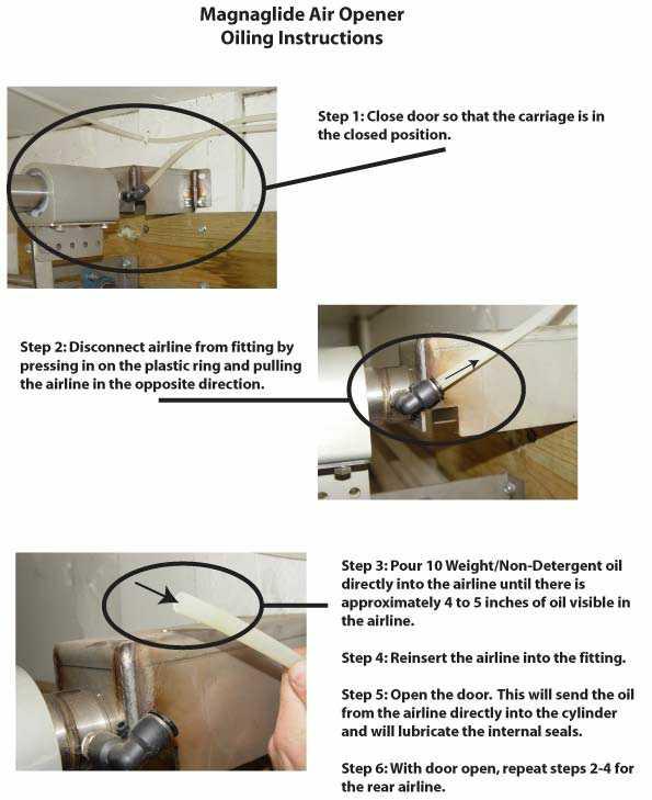
21 AIRLIFT DOORS, INC. QUARTERLY MAINTENANCE PROGRAM MAGNAGLIDE AIR OPERATOR Airlift Doors, Inc. recommends performing quarterly maintenance on your Magnaglide Air Operator. Maintenance steps explained: A. Cleaning Be sure to disconnect power to the control box and remove all air from the system before cleaning the cylinder. Failure to do so may result in serious injury. To prevent chemical buildup on the operator, the cylinder should be cleaned quarterly or more frequently if necessary. Clean the cylinder with water, mild soap, and a soft cloth. Rinse with water and dry with a non-abrasive towel or cloth B. External lubrication of cylinder Be sure to disconnect power to the control box and remove all air from the system before lubricating the cylinder. Failure to do so may result in serious injury. Spray a lubricant such as JB-80 or similar to the entire length of the cylinder. Airlift Cylinder Lubricant may also be used. Apply the cylinder lubricant directly to the cylinder with a clean rag. C. Internal lubrication of the cylinder If your control box has an automatic oiler to the right of the regulator set the automatic oiler for one drop of oil per each up and down cycle. Consult the control box owners manual for adjustment instructions. Depending on the amount of use, the oiler should be filled quarterly at a minimum. If your control box is not equipped with an automatic oiler, you can add oil manually. Close the door so that the carriage is in the closed position. Shut off the power to your control box to ensure that the door will not operate while performing maintenance. Disconnect the airline from the fitting closest to the carriage. Pour 10 weight/ non-detergent oil directly into the airline until there is approximately 4-5 inches of oil visible in the airline. Re-insert the airline back into the fitting. Turn the power back on and cycle the door to the open position. This will push the oil into the cylinder to lubricate the internal piston seals. With the door open, shut off the power and repeat to the other side of the cylinder. This step should be performed quarterly. D. Carriage lubrication Remove the bolt/plug from the side of the carriage. Using an oil can, add approximately ¼ oz. to ½ oz of 10 weight non-detergent oil into the fill hole. Replace the bolt/plug and tighten. See instructions in this manual for further information. E. Air compressor maintenance Every time you perform maintenance you should drain your compressor to reduce the amount of water contained in the system. See your air compressor manual for further information and proper drainage instructions.
22 Quarterly Maintenance Program For "Magnaglide" Air Openers Year: te: Mark date in each box when maintenance is performed to keep accurate records Steps 1st Quarter 2nd Quarter 3rd Quarter 4th Quarter A. Cleaning B. External Lubrication C. Internal Lubrication D. Carriage Lubrication E. Air Compressor 1st Quarter tes: 2nd Quarter tes: 3rd Quarter tes: 4th Quarter tes:
23 UNLIMITED Warranty for the Magnaglide Air Opener Airlift Doors, Inc. warrants to the original purchaser or original user that all Magnaglide model air openers sold by Airlift Doors, Inc. and all parts thereof are free from defects in material or workmanship under normal use and service. Airlift Doors Inc. sole obligation under this warranty shall be limited to furnishing replacement parts F.O.B Maple Lake, Minnesota for the periods specified below from the date of initial shipment by Airlift Doors, Inc. Complete Opener (3) Year These Warranties are void if the original product warranted has been damaged by accident, abuse, misuse or neglect, improper installation or service, unauthorized modifications, misapplication, or other use not arising out of defects in material and workmanship. Warranty redemption requires verification of original purchase date and completion in full of return goods form. Returns are only accepted when return authorization number has been provided by Airlift Doors, Inc. before product is returned. The warranties set out in this certificate are the exclusive remedy of the original owner or user in lieu of all other warranties written, oral or implied (including any warranty or merchantability or fitness for the purpose) and all other obligations or liabilities on the part of Airlift Doors, Inc. Airlift Doors, Inc. neither assumes nor authorizes any person to assume for it any other obligation or liability in connection with the sale, installation, or use of the Magnaglide Air Opener or any parts thereof. Airlift Doors, Inc. will not be responsible for labor or shipping and handling charges for the analysis of a defective condition or for the replacement and installation of defective parts. The warranties herein shall be null and void if the Magnaglide Air Opener is not installed by a competent contractor and/or if the Magnaglide Air Opener is not installed according to Airlift Doors, Inc. provided instructions. In no event will Airlift Doors, Inc. be responsible for, or liable to anyone for, special, indirect, collateral, punitive, incidental, or consequential damages, even if Airlift Doors, Inc. has been advised of the possibility of such damages. Such excluded damages include, but are not limited to, personal injury, damage to property, loss of goodwill, loss of profits, loss of use, cost of cover with any substitute product, interruption of business, or other similar indirect financial loss.
24 AIRLIFT DOORS, INC. RETURN GOODS AUTHORIZATION Airlift Doors, Inc. will not accept any return goods without prior authorization. Only the original purchaser is authorized to obtain return approval. If the goods were not purchased directly from Airlift Doors, Inc. please contact the Company the goods were purchased from to process the return with Airlift Doors, Inc. Return Goods Procedure Directions: Please complete this form and fax it to or to Upon review and approval of this form you will be contacted by your preferred contact method. Company: Address: City: State: Zip: Contact: Preferred method of Contact: Original Invoice #: Item(s) being returned: Part # (if known): Reason for Return: Return Terms and Conditions: All pre-approved returns must have the RGA number printed on the outside of the package All Returns must be made within 30 days of authorization. A copy of the RGA Slip and packing slip must be included with the return when replacement items have been shipped. Airlift Doors, Inc. will provide this slip with the replacement shipment. All items to be returned to: Airlift Doors, Inc RGA # 400 State Hwy. 55 Maple Lake, MN 55358
MAGNAGLIDE AIR OPERATOR VERTICAL MOUNT
 MAGNAGLIDE AIR OPERATOR VERTICAL MOUNT INSTALL GUIDE TROUBLE SHOOTING GUIDE MAINTENANCE MANUAL AIRLIFT DOORS, INC. 4700 4700 OSSEO OSSEO ROAD ROAD MINNEAPOLIS, MN MN 55430 55430 TOLL FREE: 888-368-4403
DeZURIK AFR3 Filter Regulator Used on Pneumatic Cylinder Actuators
 AFR3 Filter Regulator Used on Pneumatic Cylinder Actuators Instructions D11033 August 2013 Instructions These instructions provide information about AFR3 Filter Regulators. They are for use by personnel
LUBRICATOR GUN INSTRUCTIONS-PARTS LIST. 10,000 psi (700 bar) Maximum Delivery Pressure. Detachable-type
 Maximum Delivery Pressure. Detachable-type") INSTRUCTIONS-PARTS LIST 306 460 INSTRUCTIONS This manual contains important warnings and information. READ AND KEEP FOR REFERENCE. Rev. E Supercedes D Detachable-type LUBRICATOR GUN 10,000 psi (700 bar)
INSTRUCTIONS-PARTS LIST 306 460 INSTRUCTIONS This manual contains important warnings and information. READ AND KEEP FOR REFERENCE. Rev. E Supercedes D Detachable-type LUBRICATOR GUN 10,000 psi (700 bar)
"WHERE TUBING AND FITTINGS COME TOGETHER"
 CLEAN ROOM DEVICES, LLC "WHERE TUBING AND FITTINGS COME TOGETHER" CRD200SS TUBE EXPANDER OPERATIONS MANUAL VERSION 4.3 LAST EDITED 06.17.15 cleanroomdevices.com Table of Contents Table of Contents....1
Effective June 1, 2013 This guide supersedes all previous versions
 Effective June 1, 2013 This guide supersedes all previous versions 3842 Redman Drive 1-800-797-7974 Fort Collins, CO 80524 www.commandlight.com L-CAS THANK YOU Please allow us to express a simple thank
Spray Nozzle Adapters
 INSTRUCTIONS-PARTS LIST 306 788 INSTRUCTIONS This manual contains important warnings and information. READ AND KEEP FOR REFERENCE. First choice when quality counts. Rev. G Supersedes Rev. F DIRECTIONAL
Air Control Kit INSTRUCTIONS-PARTS LIST. Table of Contents HIGH VOLUME. 250 psi (1.7 MPa, 17.2 bar) Maximum Air Inlet Pressure
 Maximum Air Inlet Pressure") INSTRUCTIONS-PARTS LIST INSTRUCTIONS This manual contains important warnings and information. READ AND KEEP FOR REFERENCE. 308 648 Rev. B Supersedes A HIGH VOLUME Air Control Kit 250 psi (.7 MPa, 7.2 bar)
INSTRUCTIONS-PARTS LIST INSTRUCTIONS This manual contains important warnings and information. READ AND KEEP FOR REFERENCE. 308 648 Rev. B Supersedes A HIGH VOLUME Air Control Kit 250 psi (.7 MPa, 7.2 bar)
P5510. Users Manual. Pneumatic Comparison Test Pump
 P5510 Pneumatic Comparison Test Pump Users Manual PN 3952297 November 2010 2010 Fluke Corporation. All rights reserved. Printed in USA. Specifications are subject to change without notice. All product
Cincinnati, OH USA
 Part No. 87630PE Revised November 2007 Hot Dog Roller Grills Non-Stick Instruction Manual Model #8023PE, Model #8024PE and Model #8025PE Model #8023SLPE, Model #8024SLPE and Model #8025SLPE Model #8023PE
OWNER'S MANUAL L A W N R O L L E R PRT-481S BH. Safety Assembly Operation Repair Parts Maintenance. Visit us on the web!
 OWNER'S MANUAL L A W N R O L L E R ROLLER MODEL: PRC- BH PRT- BH PRT-S BH PRT-S BH Safety Assembly Operation Repair Parts Maintenance Recommended for use with Riding Mowers, Lawn or Garden Tractors, and
Pneumatic Cylinder 14 Bore X 22 Stroke Part No. R (Formerly P )
") Pneumatic Cylinder 14 Bore X 22 Stroke Part No. R434001268 (Formerly P -193419-00003) Service Information INSTALLATION Before installing this cylinder, all air lines in the system should be blown clean
Pneumatic Cylinder 14 Bore X 22 Stroke Part No. R434001268 (Formerly P -193419-00003) Service Information INSTALLATION Before installing this cylinder, all air lines in the system should be blown clean
MULTIPOSITION AIR CYLINDER
 MULTIPOSITION AIR CYLINDER CAST ALUMINUM FOUR-POSITION - ALL AIR SERVICE INFORMATION MOUNTING! Devices should be mounted and positioned in such a manner that they cannot be accidentally operated. INSTALLATION
CRD600 Automatic Fitting Inserter
 CRD600 Automatic Fitting Inserter OPERATIONS MANUAL VERSION 2.3 LAST EDITED 12.07.2018 cleanroomdevices.com 1 Table of Contents Title Page.. 1 Table of Contents. 2 1.0 General Product & Safety Information...3
Pneumatic Cylinder 14 Bore X 21 Stroke Part No. P Replaces Part No. P
 Pneumatic Cylinder 14 Bore X 21 Stroke Part No. P -322908-00000 Replaces Part No. P-191067-00000 Service Information WARNING: INSTALLATION AND MOUNTING The user of these devices must conform to all applicable
Blue Air. Commercial Refrigeration Inc. Installation & Operation Manual Chef Bases
 Blue Air Commercial Refrigeration Inc. Installation & Operation Manual Chef Bases Please read this manual completely before installing or operating this unit! BACB53 BACB71 BACB74 BACB83 BACB86 BACB96
Air Curtain. Installation, Operating and Maintenance Instructions
 Installation, Operating and Maintenance Instructions Save this manual for future reference. Air Curtain Model Numbers: ES026, ES036, ES042, ES048, ES060, ES072 READ THIS OWNER S MANUAL CAREFULLY BEFORE
DeZURIK 2 20" BOS BUTTERFLY VALVES
 2 20" BOS BUTTERFLY VALVES Instruction D10459 October 2013 2-20 BOS Butterfly Valves Instructions These instructions provide information about BOS Butterfly Valves. They are for use by personnel who are
!"" #$% "!&' ( ( ) *
 *") !"" #$% "!&' (( ) * FunPop CART Assembly Manual Model # 2689 CARTS Part No. 59411 Revised: FEB 2009 Cincinnati, OH 45241-4807 USA INSTALLATION INSTRUCTIONS Checking Shipment Unpack all cartons and check
!"" #$% "!&' (( ) * FunPop CART Assembly Manual Model # 2689 CARTS Part No. 59411 Revised: FEB 2009 Cincinnati, OH 45241-4807 USA INSTALLATION INSTRUCTIONS Checking Shipment Unpack all cartons and check
HF4145 FOLDING MULTI-POSITION WORKOUT BENCH
 HF4145 FOLDING MULTI-POSITION WORKOUT BENCH Note: Both Serial Number and Model Number are Required when Ordering Parts RECORD SERIAL NUMBER HERE CATALOG NUMBER 0406-001 Customer Service (800) 548-5438
Hollywood Racks Assembly & installation instructions for models:
 Hollywood Racks Assembly & installation instructions for models: HR1400Y (4 bike), HR1450Y (2 bike), HR1475Y, 1450Y-E & 1455Y-E (E bikes) For use on 2 hitches only. Do not use a 1 ¼ -2 hitch adapter. Maximum
CRD400 Fitting Inserter OPERATIONS MANUAL
 CRD400 Fitting Inserter OPERATIONS MANUAL ORIGINAL INSTRUCTIONS VERSION 3.4 LAST EDITED 01.07.2019 www.cleanroomdevices.com 1 Table of Contents Title Page.. 1 Table of Contents... 2 1.0 General Product
Installation Guide. Marking and Inspection Gauge. Marking Gauge. Inspection Gauge E 1. Marking and inspection gauges are combined into one gauge.
 Marking and Inspection Gauge Marking and inspection gauges are combined into one gauge. Marking Gauge The gauge has a pin and a slot for marking along the centerline. Position the pin with the end of the
OWNERS MANUAL HF4263
 OWNERS MANUAL HF4263 ADJUSTABLE AB / BACK HYPER BENCH Note: Both Serial Number and Model Number are Required when Ordering Parts RECORD SERIAL NUMBER HERE CATALOG NUMBER 0805-000 Customer Service (800)
Compressor Clutch Replacement Procedure
 Clutch Replacement Procedure P-1401-WE 819-0316 Installation Instructions An Altra Industrial Motion Company Warner Replacement Clutches for the following compressors: Denso 6E171 10P15 6P148 6C17 Ford
Customer Support
 Portable auxiliary air tanks owner's Manual aux05 aux05a aux10 WWW.CALIFORNIAAIRTOOLS.COM Customer Support 1-866-409-4581 TAbLe OF CONTeNTS INTROduCTION IntroductIon Important Safety InStructIonS components
Lubricator Gun: 10,000 psi (700 bar) Maximum Delivery Pressure when disconnected from Dispenser
 Maximum Delivery Pressure when disconnected from Dispenser") INSTRUCTIONS-PARTS LIST 30 455 INSTRUCTIONS This manual contains important warnings and information. READ AND KEEP FOR REFERENCE. Rev. C Supercedes B Hand-Operated Portable Grease Dispenser Buckshot Luber
INSTRUCTIONS-PARTS LIST 30 455 INSTRUCTIONS This manual contains important warnings and information. READ AND KEEP FOR REFERENCE. Rev. C Supercedes B Hand-Operated Portable Grease Dispenser Buckshot Luber
CRD610 Automatic Fitting Inserter
 CRD610 Automatic Fitting Inserter OPERATIONS MANUAL VERSION 1.2 LAST EDITED 12.12.2018 cleanroomdevices.com 1 Table of Contents Title Page. 1 Table of Contents...2 1.0 General Product & Safety Information....3
Reach ins, Freeezers & Refrigerators Installation & Operation Manual
 Reach ins, Freeezers & Refrigerators Installation & Operation Manual BSR23 BSF23 BSR49 BSF49 BSR72 BSF72 IMPORTANT SAFETY INSTRUCTIONS (SAVE THESE INSTRUCTIONS) Visit us on the web at www.blueairinc.com
CLEAN ROOM DEVICES, LLC "WHERE TUBING AND FITTINGS COME TOGETHER"
 CLEAN ROOM DEVICES, LLC "WHERE TUBING AND FITTINGS COME TOGETHER" CRD400 Fitting Inserter OPERATIONS MANUAL VERSION 3.1 LAST EDITED 03.08.11 DOCUMENT NUMBER 001 cleanroomdevices.com 1 Table of Contents
MetroPrime 22MPC Self-Priming Centrifugal Pump
 Page 1 of 6 prevent priming or reduce pump capacity. OPERATION The 22 MPC-Metropolitan Pump is a self-priming centrifugal pump and only requires priming prior to its initial start. The pump will retain
Procedure to Install the New Autogap components in ER-1225 and ER825 Brake with inverted Armature Hub
 Procedure to Install the New Autogap components in ER-15 and ER85 Brake with inverted P-30-1 819-0376 Installation & Operating Instructions Contents Introduction........................... Kit Parts List..........................
Blue Air. Commercial Refrigeration Inc. Installation & Operation Manual Glass Door Countertop Refrigerator
 Blue Air Commercial Refrigeration Inc. Installation & Operation Manual Glass Door Countertop Refrigerator Please read this manual completely before installing or operating this unit! BAGR7 Blue Air reserves
37SCENE 46SCENE 79SCENE
 Installation and Operation Instructions LED SCENE LIGHT LED SCENE LIGHT 37SCENE 46SCENE 79SCENE 37SCENE 46SCENE Introduction The 37SCENE, 46SCENE, 79SCENE LED Scene Lights are designed for the emergency
CLEAN ROOM DEVICES, LLC "WHERE TUBING AND FITTINGS COME TOGETHER"
 CLEAN ROOM DEVICES, LLC "WHERE TUBING AND FITTINGS COME TOGETHER" CRD600 Automatic Fitting Inserter OPERATIONS MANUAL VERSION 2.1 LAST EDITED 7.25.14 DOCUMENT NUMBER 001 cleanroomdevices.com 1 Table of
ECONOMAIR SERIES CYLINDERS
 OPERATOR S MANUAL INCLUDING: APPLICATION, LUBRICATION, INSTALLATION & SERVICE ECONOMAIR SERIES CYLINDERS 2XXX-XXX9-XXX RELEASED: 9-14-92 REVISED: 3-6-01 (REV. B) READ THIS MANUAL CAREFULLY BEFORE INSTALLING,
Adjustable Shop Stool with Backrest
 Adjustable Shop Stool with Backrest Owner s Manual WARNING: Read carefully and understand all ASSEMBLY AND OPERATION INSTRUCTIONS before operating. Failure to follow the safety rules and other basic safety
OWNER S MANUAL Z SERIES TRACKS. Rev. 355_05
 OWNER S MANUAL Z SERIES TRACKS Rev. 355_05 LOEGERING 800-373-5441 15514 37 th Street SE 701-347-5441 Casselton, ND 58012 USA Fax: 701-347-4323 E-Mail: lmi@loegering.com Internet: www.loegering.com Loegering
Instruction Sheet SRSR SERIES. Rotating Sliding Rail System
 Instruction Sheet SRSR SERIES Rotating Sliding Rail System THANK YOU Thank you for purchasing the SRSR Series Rotating Sliding Rail System. Please read these instructions thoroughly before assembling this
TACTIK Factory Taillight Euro-Guards
 TACTIK Factory Taillight Euro-Guards Installation Manual: for 07- Current Jeep Wrangler JK # 13117.0101 and # 13117.0201 Passenger PARTS LIST: Driver Side Taillight Euro-Guard - QTY 1 Passenger Taillight
Owner s Manual SB5010 Broadcast Spreader. Caution: Read all Safety Instructions and Operating Instructions Carefully.
 Manufacture s Limited Warranty for Broadcast Spreader Owner s Manual SB00 Broadcast Spreader The limited warranty set forth below is given by Precision Products Incorporated with respect to new merchandise
Kit INSTALLATION GUIDE. For maximum effectiveness and safety, please read these instructions completely before proceeding with installation.
 Kit 25690 MN-369 (111512) ECR 8349 INSTALLATION GUIDE For maximum effectiveness and safety, please read these instructions completely before proceeding with installation. Failure to read these instructions
CLEAN ROOM DEVICES, LLC "WHERE TUBING AND FITTINGS COME TOGETHER"
 CLEAN ROOM DEVICES, LLC "WHERE TUBING AND FITTINGS COME TOGETHER" CRD600AF Automatic Fitting Inserter With Auto Feed OPERATIONS MANUAL (Shown with optional alcohol dispenser) 1 VERSION 1.1 LAST EDITED
Read this entire manual before operation begins.
 Read this entire manual before operation begins. Record below the following information which is located on the serial number data plate. Serial No. Model No. Date of Installation Contents Specifications.............
Motorized Stainless 2-Way Valves
 Installation and Operation Manual Motorized Stainless 2-Way Valves Safety Valve ETV Applications WARNING This Heat-Timer valve is strictly an operating valve; it should never be used as a primary limit
Hot Dog Roller Grills Instruction Manual Model #8023, Model #8024 and Model #8025 Model #8023SL, Model #8024SL and Model #8025SL
 Part No. 87630 Revised November 2007 Hot Dog Roller Grills Instruction Manual Model #8023, Model #8024 and Model #8025 Model #8023SL, Model #8024SL and Model #8025SL Model #8023 shown Cincinnati, OH 45241-4807
Thank you for purchasing a 911EP GALAXY Light Bar! Every light bar is carefully inspected for defects prior to shipment.
 OWNER S MANUAL Safety First Thank you for purchasing a 911EP GALAXY Light Bar! Every light bar is carefully inspected for defects prior to shipment. Questions or Concerns? 911EP wants to quickly resolve
OWNERS MANUAL HF4550 PREACHER CURL. Customer Service (800) (858) Fax (858) RECORD SERIAL NUMBER HERE
 (858) Fax (858) RECORD SERIAL NUMBER HERE") OWNERS MANUAL HF4550 PREACHER CURL Note: Both Serial Number and Model Number are Required when Ordering Parts RECORD SERIAL NUMBER HERE CATALOG NUMBER 0805-001 Customer Service (800) 548-5438 (858) 578-7676
OWNERS MANUAL HF4550 PREACHER CURL Note: Both Serial Number and Model Number are Required when Ordering Parts RECORD SERIAL NUMBER HERE CATALOG NUMBER 0805-001 Customer Service (800) 548-5438 (858) 578-7676
Stainless Steel Air Motor Conversion Kits
 Instructions Stainless Steel Air Motor Conversion Kits 096B Conversion Kit 650 For 00 Pumps Conversion Kit 65 For 590 Pumps Conversion Kit 65 For 50 Pumps Model 650 Model 65 Model 65 Graco Inc. P.O. Box
OWNERS MANUAL HF PAIR VERTICAL DUMBBELL RACK. Customer Service (800) (858) Fax (858) RECORD SERIAL NUMBER HERE
 (858) Fax (858) RECORD SERIAL NUMBER HERE") OWNERS MANUAL HF4459 5 PAIR VERTICAL DUMBBELL RACK Note: Both Serial Number and Model Number are Required when Ordering Parts RECORD SERIAL NUMBER HERE CATALOG NUMBER 0605-000 Customer Service (800) 548-5438
OWNERS MANUAL HF4459 5 PAIR VERTICAL DUMBBELL RACK Note: Both Serial Number and Model Number are Required when Ordering Parts RECORD SERIAL NUMBER HERE CATALOG NUMBER 0605-000 Customer Service (800) 548-5438
APCO ASR-400/450 SEWAGE AIR RELEASE VALVES
 APCO ASR-400/450 SEWAGE AIR RELEASE VALVES Instruction D12005 December 2012 Instructions These instructions provide installation, operation and maintenance information for the APCO ASR- 400/450 Sewage
OnBoard Drum Major Podium
 Assembly and Owner s Manual OnBoard Drum Major Podium CONTENTS CONTENTS................................................................................. 1 SAFETY...................................................................................
OWNERS MANUAL HF
 OWNERS MANUAL HF4461-48 HORIZONTAL DUMBBELL RACK Note: Both Serial Number and Model Number are Required when Ordering Parts RECORD SERIAL NUMBER HERE CATALOG NUMBER 1005-000 Customer Service (800) 548-5438
ROUSH Short Throw Shifter Kit
 ROUSH Short Throw Shifter Kit Part Number 1310R7400 Application: 2010 Ford Mustang GT Installation Instructions Before installing your ROUSH Performance Product(s), read through the entire installation
Installation & Operation Manual Chef Base
 Installation & Operation Manual Chef Base Please read this manual completely before installing or operating this unit! BACB53 BACB53M BACB71 BACB71M BACB74 BACB74M BACB83 BACB83M BACB86 BACB86M BACB96
Level One Electric Vehicle Charging Station FREE STANDING Product Guide
 Level One Electric Vehicle Charging Station FREE STANDING Product Guide Model # SC2-120 Shorepower Technologies 2351 NW York St. Portland, OR 98664 503-892-7345 info@shorepower.com www.shorepower.com 2
APCO CRF-100A RUBBER FLAPPER SWING CHECK VALVES
 APCO CRF-100A RUBBER FLAPPER SWING CHECK VALVES Instruction D12043 June 2016 DeZURIK Instructions These instructions provide installation, operation and maintenance information for APCO CRF-100A Rubber
Model NTX7 Series Automatic Battery Charger User s Manual Rev. 1.0 October 17, 2006
 B R A N D Model NTX7 Series Automatic Battery Charger User s Manual Rev. 1.0 October 17, 2006 For Sales, Support and Service phone: 407-331-4793 fax: 407-331-4708 website: www.xenotronix.com email: information@xenotronix.com
Air Control Kits INSTRUCTIONS-PARTS LIST. Table of Contents HIGH VOLUME. 250 psi (1.7 MPa, 17.2 bar) Maximum Air Inlet Pressure
 Maximum Air Inlet Pressure") INSTRUCTIONS-PARTS LIST INSTRUCTIONS This manual contains important warnings and information. READ AND KEEP FOR REFERENCE. 308 722 Rev. A HIGH VOLUME Air Control Kits 250 psi (.7 MPa, 7.2 bar) Maximum
INSTRUCTIONS-PARTS LIST INSTRUCTIONS This manual contains important warnings and information. READ AND KEEP FOR REFERENCE. 308 722 Rev. A HIGH VOLUME Air Control Kits 250 psi (.7 MPa, 7.2 bar) Maximum
Stainless Steel Air Motor Conversion Kits
 Instructions Stainless Steel Air Motor Conversion Kits 096D Conversion Kit 650 For 00 Pumps Conversion Kit 65 For 590 Pumps Conversion Kit 65 For 50 Pumps Model 650 Model 65 Model 65 Installation Pressure
DRAGO. Corn Header Manual f HEADSIGHT.COM
 DRAGO Corn Header Manual 09020801f HEADSIGHT.COM 574.546.5022 About Headsight Headsight Contact Info Headsight, Inc. 4845 3B Road Bremen, IN 46506 Phone: 574-546-5022 Fax: 574-546-5760 Email: info@headsight.com
203 TRANSFER CASE CONVERSION
 203 TRANSFER CASE CONVERSION PN:501 OUR FOUR TRANSFER CASE WEDGES REPLACE THE SPIDER GEARS AND CONNECT THE PLANETARY GEAR AND REAR OUTPUT SHAFT MAKING ONE UNIT. SIMILAR IN DESIGN & FUNCTION TO THE BEST
Installation Instructions Sunrider for Hardtop
 Installation Instructions Sunrider for Hardtop Installation Instructions Sunrider for Hardtop Vehicle Application: Jeep Wrangler / Wrangler Unlimited 2007- current Part Number 52450 Installation Tips Before
Read this entire manual before operation begins.
 Read this entire manual before operation begins. Record below the following information which is located on the serial number data plate. Serial No. Model No. Date of Installation Contents Specifications.............
Model , Series A 9 in. (23 cm) roller frame with 45 angle and 12 in. reach 1/2 in. (13 mm) nap roller cover
 roller frame with 45 angle and 12 in. reach 1/2 in. (13 mm) nap roller cover") Operating Instructions 309899 Rev. A This manual contains important warnings and information. READ AND KEEP FOR REFERENCE. INSTRUCTIONS Manufactured by Model 246818, Series A 9 in. (23 cm) roller frame
Operating Instructions 309899 Rev. A This manual contains important warnings and information. READ AND KEEP FOR REFERENCE. INSTRUCTIONS Manufactured by Model 246818, Series A 9 in. (23 cm) roller frame
Safety Sentry Electronic Breakaway Switch
 Safety Sentry Electronic Breakaway Switch P-616-WE 819-0454 Installation Instructions An Altra Industrial Motion Company Parts List Mounting hardware included with the Safety Sentry Breakaway Switch kit:
Instruction Manual. Fudge Puppy Display Case
 Instruction Manual Fudge Puppy Display Case Model No. 5535 10700 Medallion Drive, Cincinnati, Ohio 45241-4807 USA 2014 Gold Medal Products Co. Part No. 89074 SAFETY PRECAUTIONS DANGER Machine must be properly
OWNERS MANUAL HF4261
 OWNERS MANUAL HF4261 ADJUSTABLE AB BENCH Note: Both Serial Number and Model Number are Required when Ordering Parts RECORD SERIAL NUMBER HERE CATALOG NUMBER 0905-000 Customer Service (800) 548-5438 (858)
Old Proportioning Pumps
 Repair - Parts Old Proportioning Pumps 311391F For proportioning pumps on Gusmer and Old Graco H-25 and H-XP2 Hydraulic Proportioners. Important Safety Instructions Read all warnings and instructions in
Operating and Installation Instructions
 Model Number 20902 Fabricator's Power Module Kit - Aluminum Operating and Installation Instructions CAUTION! This product is to be installed only by persons knowledgeable in the repair and modification
ATD Gallon Pressurized Oil Drain Owner s Manual
 ATD-5203 30 Gallon Pressurized Oil Drain Owner s Manual TECHNICAL SPECIFICATIONS Model: ATD-5203 Capacity: 30 Gallon Drain Funnel Working Height: 47.25 to 70.5 Drain Funnel Diameter: 15.75 Plastic Tray:
PFS Rotameter. Variable Area Flowmeter. Instruction Manual PFS-RM200, RM230, RM250
 PFS Rotameter 09/2018 Rev. 0 Variable Area Flowmeter Instruction Manual PFS-RM200, RM230, RM250 Please note: This instruction manual provides detailed information and instructions that must be read, understood
Pump/Manifold Kits. Instructions F ENG. To convert E-Flo 4-Ball Piston Pumps to a different size lower. For professional use only.
 Instructions Pump/Manifold Kits 311611F ENG To convert E-Flo 4-Ball Piston Pumps to a different size lower. For professional use only. See page 2 for a list of available kits. Important Safety Instructions
Installation Instructions Twill Replace-a-top
 Installation Instructions Twill Replace-a-top Upper Door Skins Not Included Vehicle Application Jeep Wrangler TJ 1997-2006 Tinted Glass Windows Part Number: 79841 www.bestop.com - We re here to help! Visit
Microscope light manual
 Microscope light manual LS-12 and LS-14 LS-12 LS-14 1/9 Content Overview... 3 Mounting... 4 Light adjustment... 5 Mirror... 6 Filters... 6 Replacing microscope light... 7 Technical data... 8 Troubleshooting...
INSTRUCTIONS PARTS LIST
 INSTRUCTIONS PARTS LIST 30812 This manual contains important warnings and information. READ AND RETAIN FOR REFERENCE See manual 308393 for complete gun washer warnings and instructions. Rev. B AIR SPRAY
DeZURIK KUL KNIFE GATE VALVES
 KUL KNIFE GATE VALVES Instruction D11025 September 2013 Instructions These instructions are intended for personnel who are responsible for the installation, operation and maintenance of your KUL knife
Electrically Released Motor Brake Module for EM-MBFB and EUM-MBFB
 Electrically Released Motor Brake Module for EM-MBFB and EUM-MBFB P-1337-WE 819-0314 Installation Instructions An Altra Industrial Motion Company Warner Electric s MBFB series of Electrically Released
Pressure Washer Hose Reel
 Pressure Washer Hose Reel Owner s Manual WARNING: Read carefully and understand all ASSEMBLY AND OPERATION INSTRUCTIONS before operating. Failure to follow the safety rules and other basic safety precautions
Installation Instructions for Drapery System Drapery
 Installation Instructions for Drapery System 5060 Drapery - 5060 Table of Contents Tools Required: Power Screwdriver w/phillips bit Installing the 5060.............................. 3 Splicing the 5060...............................4
MODEL G300 BRAKE BLEEDER
 MODEL G300 BRAKE BLEEDER Installation, Operation & Repair Parts Information Branick Industries, Inc. 4245 Main Avenue P.O. Box 1937 Fargo, North Dakota 58103 REV120716 P/N: 81-0035H THIS PAGE INTENTIONALLY
RCV-V PNEUMATIC DIRECTIONAL CONTROL VALVE
 RCV-V PNEUMATIC DIRECTIONAL CONTROL VALVE Part Number R434005262 (Valve Assembly Less Mounting Risers) Part Number R434005983 (Valve Assembly With Mounting Risers) Service Information Valve Only The RCV-V
TYPE S RELAY VALVE (Volume booster) Service Manual
 Service Manual") TYPE S RELAY VALVE (Volume booster) Service Manual The Type "S" Relay Valve is a pilot operated, 3-way, pneumatic pressure control valve with open exhaust. This large capacity valve receives pressure signals
TYPE S RELAY VALVE (Volume booster) Service Manual The Type "S" Relay Valve is a pilot operated, 3-way, pneumatic pressure control valve with open exhaust. This large capacity valve receives pressure signals
Installation Instructions
 Installation Instructions Trektop Doors not included Vehicle Application Jeep Wrangler Unlimited 2007 2011 Part Number: 56805 www.bestop.com - We re here to help! Visit our web site and click on Ask a
Assembly Instructions
 Assembly Instructions Questions, problems, or missing parts? Before returning to the store, call Royal Garden Customer Service. 866-988-3300 8 a.m. -5 p.m., PST Monday - Friday Retain this manual for future
POST LANTERN ITEM # MODEL #39487 ATTACH YOUR RECEIPT HERE. Serial Number. Purchase Date
 ITEM #356-4981 POST LANTERN MODEL #39487 ATTACH YOUR RECEIPT HERE Serial Number Purchase Date Questions, problems, missing parts? Before returning to your retailer, call our customer service department
Kitchen Tech Series Air Curtain
 Installation, Operating, and Maintenance Instructions Save this manual for future reference. Kitchen Tech Series Air Curtain Model Numbers: KTECH026, KTECH036, KTECH042, KTECH048, KTECH060, KTECH072, KTECH084,
Air and water reels. Models and Series B. Installation and maintenance guide DANGER
 Installation and maintenance guide Air and water reels Models 83753 and 83754 Series B Date of issue June 2014 Form number 404665A Section E35 Page 83A DANGER Read manual prior to installation or use of
Adjustable Angled Incline Conveyor Owners Manual with Operating Instructions
 Adjustable Angled Incline Conveyor Owners Manual with Operating Instructions Revision 012211 Table of Contents Basic Conveyor Features 3 Getting Started 4 Setting Up the Incline Conveyor 5 Belt Removal
Installation Instructions Twill Replace-a-top
 Installation Instructions Twill Replace-a-top Upper Door Skins Not Included Vehicle Application Jeep Wrangler TJ 2003-2006 Tinted Glass Windows Part Number: 79841 www.bestop.com - We re here to help! Visit
POST LANTERN ITEM # MODEL #39434 ATTACH YOUR RECEIPT HERE. Serial Number. Purchase Date
 ITEM #356-4894 POST LANTERN MODEL #39434 ATTACH YOUR RECEIPT HERE Serial Number Purchase Date Questions, problems, missing parts? Before returning to your retailer, call our customer service department
4-Ton Electric Log Splitter
 4-Ton Electric Log Splitter Questions: Support@Powrkraft.com PK65556 2 18ga. @ 20ft, 16ga. @ 50ft, 14 ga. @ 75ft. 12ga @ 100ft, 10ga @ 200ft These are minimum cord requirements. 13-16 Model Number 65556
15H882 Slider Bearing Kit
 Instructions 15H882 Slider Bearing Kit 311616D ENG To replace slider bearings on E-Flo 4-Ball Piston Pumps. For professional use only. Important Safety Instructions Read all warnings and instructions in
HATCHGRIP Installation Instructions/Operation and Maintenance Manual
 HATCHGRIP Installation Instructions/Operation and Maintenance Manual Models: HTG-PCG Contact Information Table of Contents: Safety Precautions... 2 Product Information... 2 Operation... 3 Installation
Installation Instructions Trektop
 Installation Instructions Trektop Vehicle Application Jeep Wrangler (JK) Unlimited 2007 Current Part Number: 56805 www.bestop.com - We re here to help! Visit our web site and click on Ask a Question. Click
Assembly Instructions
 Assembly Instructions Aluminum Padded Sling Chaise Lounge Questions, problems, or missing parts? Before returning to the store, call Customer Service. -866-988-3300 8 a.m. -5 p.m., PST Monday - Friday
Installation Instructions Twill Replace-a-top with Tinted Windows
 Installation Instructions Twill Replace-a-top with Tinted Windows Vehicle Application Jeep Wrangler Unlimited (JK) 4 Door 2007 2009 Part Number: 79837 Upper Door Skins not included www.bestop.com - We
Installation Instructions SRC Over-Size Tire Carrier Jeep Wrangler/Unlimited Part # 2743
 NOTE: Carefully read instructions entirely before assembling/installing this product. Parts Included Qty Parts Included Qty Tire Carrier 1 8 x 70mm Hex Bolt 4 Brake Light Bracket 1 8mm Flat Washer 4 Tire
Operator s Manual. Twin Rear Bagger For FastAttach Compatible Lawn Tractors
 Operator s Manual Twin Rear Bagger For FastAttach Compatible Lawn Tractors Models OEM-190-601 (for 38-inch & 42-inch decks) OEM-190-602 (for 46-inch decks) MTD PRODUCTS INC. P.O. BOX 368022 CLEVELAND,
OWNER S MANUAL. LOEGERING th Street SE Casselton, ND USA Fax:
 OWNER S MANUAL TRAIL BLAZERS and D SERIES TRACKS LOEGERING 800-373-5441 15514 37 th Street SE 701-347-5441 Casselton, ND 58012 USA Fax: 701-347-4323 E-Mail: lmi@loegering.com Internet: www.loegering.com
Model 0390 EZFILL TOP FILL MULTIFEED KIT WITH 1.32 GAL. (5L) CONTAINER EZFILL KIT* INSTALLATION AND MAINTENANCE GUIDE
 CONTAINER EZFILL KIT* INSTALLATION AND MAINTENANCE GUIDE") Model 0390 EZFILL KIT* EZFILL TOP FILL MULTIFEED KIT WITH.32 GAL. (5L) CONTAINER INSTALLATION AND MAINTENANCE GUIDE 3070623 Rev G 20 July 205 Space Provided For Owner Notes * EZFILL KIT pictured with optional
Model 0390 EZFILL KIT* EZFILL TOP FILL MULTIFEED KIT WITH.32 GAL. (5L) CONTAINER INSTALLATION AND MAINTENANCE GUIDE 3070623 Rev G 20 July 205 Space Provided For Owner Notes * EZFILL KIT pictured with optional