INSTALLATION GUIDE. JK v8 Hemi builder kit 5.7L, 6.1L, 6.4L hemi JK- swb, lwb. AEV30207AB Last Updated: 07/14/17
|
|
|
- Candice Patterson
- 6 years ago
- Views:
Transcription
1 JK v8 Hemi builder kit 5.7L, 6.1L, 6.4L hemi JK- swb, lwb AEV30207AB Last Updated: 07/14/17 INSTALLATION GUIDE
2 table of contents 1. Overview 1 2. Engine and Transmission Mounts 9 3. Wiring Battery Tray Steering Shaft Relocation Plumbing Exhaust 35 PLEASE NOTE THAT THIS KIT HAS NOT BEEN TESTED TO COMPLY WITH FMVSS STANDARDS AND MUST NOT BE INSTALLED IN ANY NEW VEHICLE PRIOR TO DELIVERY TO THE END USER. WHILE ALL CORRECT EMMISSIONS EQUIPMENT IS DESIGNED TO BE INSTALLED WITH THIS KIT, THIS KIT MAY STILL NOT BE LEGAL FOR ON-ROAD USE IN ALL STATES OR COUNTRIES AND AS SUCH IS CURRENTLY INTENDED FOR OFF-ROAD USE ONLY. IT IS THE USERS RESPONSIBILITY TO COMPY WITH ALL REGULATIONS. AEV DOES NOT RECOMMEND ANY MODIFICATIONS TO HEMI ENGINES OR TRANSMISSIONS. TECH SUPPORT CAN NOT BE PROVIDED FOR ANY CONVERSIONS USING AFTERMARKET PERFORMANCE PARTS INCLUDING BUT NOT LIMITED TO CAMSHAFTS, HEADS, EXHAUST MANIFOLDS, AFTERMARKET EXHAUSTS, INTAKES, THROTTLE BODIES, PERFORMANCE ECU CALIBRATIONS, STROKER KITS, SUPERCHARGERS, TURBOCHARGERS, SHIFT KITS OR ANY OTHER NON PRODUCTION ITEM. ii
3 PLEASE READ BEFORE YOU START TO GUARANTEE A QUALITY INSTALLATION, WE RECOMMEND READING THESE INSTRUCTIONS THOROUGHLY BEFORE BEGINNING ANY WORK. THESE INSTRUCTIONS ASSUME A SUBSTANTIAL AMOUNT OF MECHANICAL ABILITY AND ARE NOT WRITTEN NOR INTENDED FOR SOMEONE NOT FAMILIAR WITH AUTO REPAIR. INCLUDED PARTS QTY REQUIRED TOOLS This product is covered under the AEV Parts Limited Warranty, a copy of which can be found at aev-conversions.com/warranty. iii
4 part I: Overview and Tips Congratulations on purchasing your AEV JK HEMI Installation kit. These instructions have been written for shops or DIY individuals with experience in general mechanics and welding. AEV also assumes that this kit will be installed in a shop environment with access to general shop equipment. If you are not familiar with JK systems, please reference the Jeep Service Manual available at any Chrysler dealership.in order to help facilitate installation, we have composed a series of tips below: This kit requires a Grand Cherokee engine. If using a 2011 engine you must change the water pump and crank pulley to parts. TIP 1: Although it is not required, AEV recommends using a two post hoist to remove the body from the vehicle. The Jeep JK Wrangler was designed by Chrysler to have the body and chassis built as two complete assemblies which are then mated together on the assembly line, because of this; removal of the body only requires about 45 minutes. The general procedure is outlined below: 1. Discharge the AC system 2. Disconnect the steering shaft at the firewall. 3. Disconnect the appropriate brake lines at the ABS Module. 4. Disconnect the battery harness from the battery, firewall, and right front fender. 5. Unplug the 34 way powertrain connector at the firewall (C100) and the 34 way Chassis connector (C300) on the right hand side of the radiator. 6. Unplug the PCM (C1, C2, C3, and C4.) Remove the harness from left front fender and firewall. 7. Disconnect the front left O2 sensor located below the master cylinder (pre-2011) or on the firewall (post-2011.) 8. Drain and disconnect the radiator and heater hoses. 9. Disconnect the transmission cooler lines at the radiator. 10. Remove the power steering reservoir from the body. 11. Disconnect the vacuum line from the brake booster and firewall. 12. Disconnect the ground strap from the hood and firewall. 13. Remove the battery tray and air filter 14. Remove the heater core hoses from the engine. 15. Remove the drive shafts 16. Remove the trailer harness if equipped. 17. Remove all the body mounts 18. Disconnect the emergency brake cables at the rear axle. 19. Disconnect the transmission and transfer case cables 20. Disconnect the fuel fill hose. 21. Disconnect all vapor lines at the purge valve. 22. Disconnect the top of the rear axle vent line. 1
5 Once the body is separated, it is easy to remove the stock powertrain, weld in the new mounts and to install the assembled 5.7, 6.1L, or 6.4L powertrain and exhaust into the chassis. While the body is on the hoist, the completed cooling module, and steering modifications can be completed. The body is then mated back to the chassis using the reverse procedure, the harnesses are plugged in, the brake lines are hooked back up and bled, the radiator hoses can then be connected and the vehicle can be filled with fluid and started. TIP 2: There are several variations of sensors, alternators, water pumps, crank pulleys, and power steering pumps used in different applications from 2005 onward. Please check that you have all the correct parts listed in the Bill of Materials provided on our website. Using the wrong part can cause serious damage to other components. TIP 3: The exhaust system is designed to fit the 5.7L motor in a stock application. 6.1L and 6.4L motors use the 5.7 exhaust but will be required to use the 5.7L Manifolds, Gaskets, and bolts also listed in the Bill of Materials. The routing has been fitted assuming a stock suspension and bumpers. The use of aftermarket suspensions, bumpers or other components may require modifications to the exhaust system or other components. Two Door Wranglers will need a section of tail pipe cut out of the system. TIP 4: Jeep Wranglers being converted from Manual to Automatic Transmissions will require AEV Part # AA which is an additional wire for the body side of the harness. The other parts required to perform the manual to automatic conversion are listed in the Bill of Materials. TIP 5: Four door wranglers can use the stock driveshaft s front and rear; two door models will need a new or modified rear driveshaft. TIP 6: WK and XK powertrains come with a rear sump aluminum oil pan (plastic pan on 2011s must be changed.) This pan will work but is easily damaged off-road. As an option, a steel pan is available from the Dodge Ram and all parts are listed in the supplied Bill of Materials. LX powertrains come with a front sump aluminum pan and will need to be changed to the steel pan. Be sure to reference a 5.7 manual regarding the Torque To Yield main bearing cap bolt and always use a new bolt. 2

6 TIP 7: The stock JK transfer case cable bracket must be modified in order to clear the floorpan as shown in Figure 1. TIP 8: Fig. 1 The AEV Harness is the same for 5.7L, 6.1L, and 6.4L conversions. There are two connectors included that are for the 5.7L engines only and must be tied up on 6.1L conversions. TIP 9: The MDS (Gray) connector located at the top rear of block must be zip tied to the harness and will not be used for 6.1L. The EGR solenoid connector (black 6-way) located at the front right of engine has a plastic clip located in the connector which is designed to fasten under the AEV air filter bracket on any conversions without EGR. 5.7 conversions can utilize the Grand Cherokee or Commander engine cover however it must be modified prior to installation using the template provided in Figure 2. For 6.4L conversions, you can utilize the Grand Cherokee valve covers but the driver s side needs to be modified. See Figure 3 illustrating the portion to be removed. TIP 10: The new position of the V8 motor on top of and in front of the front axle causes approximately 430 lbs of weight to be shifted to the front axle and suspension. Stock springs will see approximately 1 of drop, aftermarket springs will vary depending on the manufacturer of the springs. 3


7 Fig. 3 TIP 11: Use only Mopar +4 Transmission Fluid and Mopar Coolant. Other brands may harm the seals or cause cooling problems. Tip 12. Position the V8 Decals as shown in Figure 4. Fig. 4 4


8 AC compressor modification The 3.8L AC Compressor must be modified to clear the steering gear. A. Using a 7/8-in countersink bit, drill out the factory hole as shown. B. Use a grinder to bevel the corner of the mounting point as shown. C. Grind the raised portion of housing flush as shown. a. B. before after C. C. before after 5

9 A. Mount AC compressor to engine block. Use the supplied flat head bolt in the upper mounting hole, a factory bolt in the lower, and a factory bolt in the rear with the supplied spacer between the compressor and engine block. supplied bolt supplied spacer factory bolts 6

10 FIG 2 hemi cover edge Remove this section of plastic * Retain this side of the paper to align with shape of hemi cover edge / hemi badging H. cut along these lines 1in 1in hemi badging H
11 8


12 Part II: Engine & transmission mounting 5.7L, 6.1L, and 6.4L WK or XK Powertrains with Dodge 4WD Adapter in place JK SWB, LWB, LHD only a. mounting preparation 1. After the 3.8L Powertrain is removed, disconnect the front ABS connectors at the frame and remove the right side wiring harness bolt on clips that are located on the frame behind the right side shock tower. 2. Cut off the OE engine mounts from the frame and clean up the area with a sanding disc. b. installation of the engine mounts 1. Each engine mount has an L or R inscribed into the metal indicating the Left from the Right. There is also an arrow indicating the front of the mount. 2. Place the mounts on the frame rail and line up the oval holes precisely. Tack in place and finish weld as shown in Figure Paint all bare areas as required. 4. Reinstall the wiring harness mount with the stock hardware (Figure 2.) Fig. 1 9

13 Fig. 2 c. installation of the transmission mount 1. All 5 45 Transmissions must have the 3/4 Ton or 1 Ton Dodge 4WD adapter (Mopar AB) installed prior to the transmissions mount. 2. Install the AEV Mount to the 4WD Adapter on the transmission using the stock bolts. 3. Install the stock JK transmission isolator to the AEV Transmission Mount using the two 3/8 x 1 bolts, nuts, and washers and two 1/2 x 1 bolts, nuts, and washers. D. installation of the cross-member mount 1. Begin by bolting the top plate of the transmission cross member mount to the JK transmission isolator using the stock hardware. 2. Bolt the top plate of the transmission cross member mount to the JK cross member using 4 of the 1/2 13 bolts, washers, and flange nuts. 3. Bolt the top plate of the transmission cross member mount to the bottom of the JK cross member using three of the stock bolts into the cross member nutserts. Drill out one hole using the bottom plate as a drill template. Use the remaining two 1/2 13 bolts, washers and flange nuts to secure the bottom plate to the cross member. 4. Weld top and bottom plates as shown (Figure 3.) 5. Paint any raw material and welds. 10
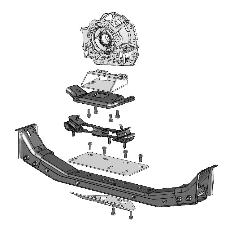
14 Fig. 3 11
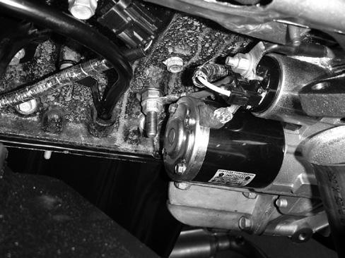
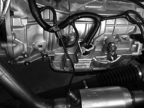
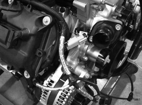
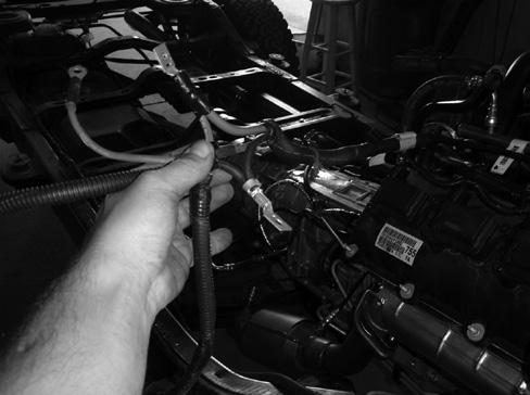
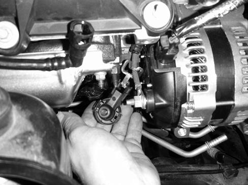
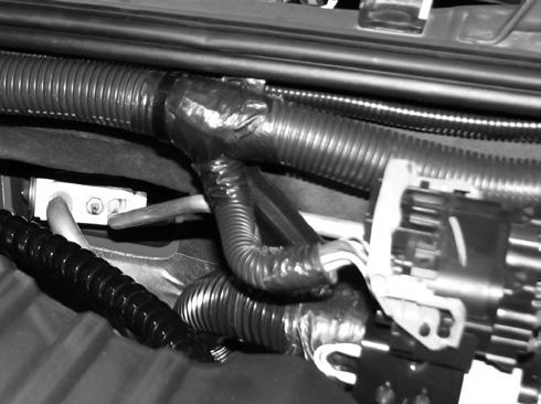
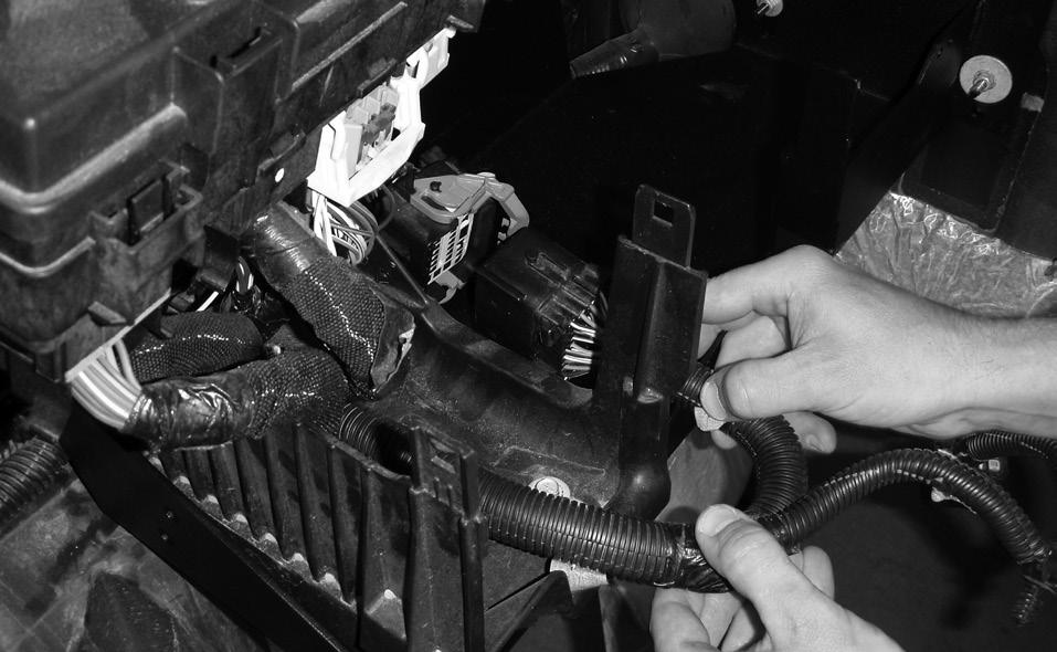
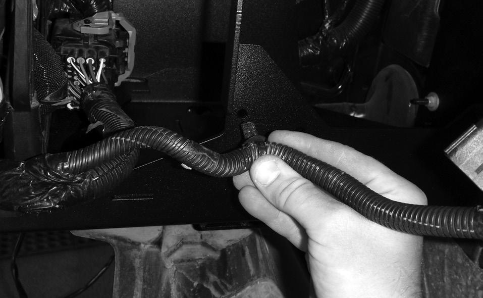
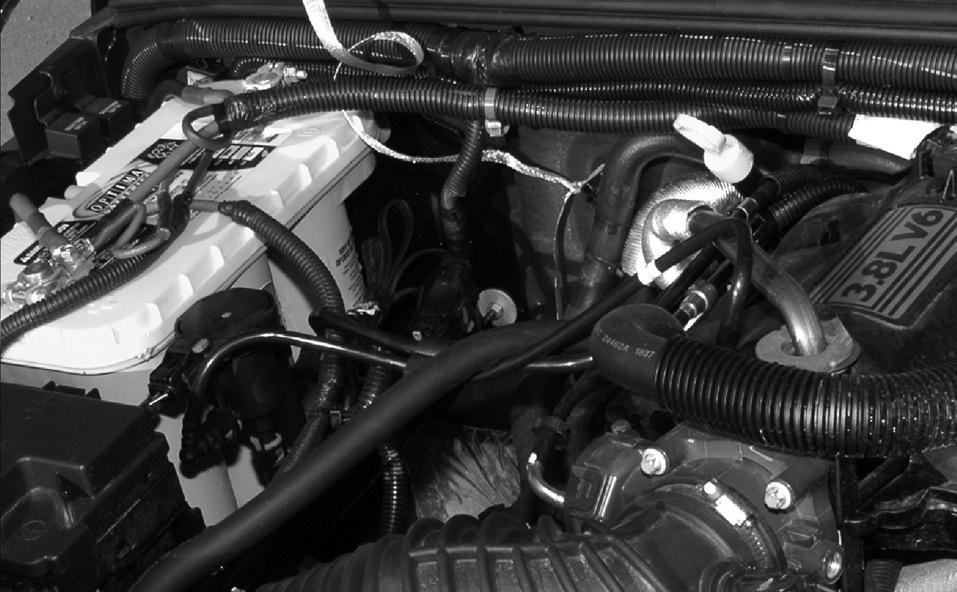
15 Part III: wiring harness installation Every AEV HEMI JK Wiring Harness is 100% computer checked for quality and accuracy before shipment. The harness is installed and routed the same way as a factory Grand Cherokee or Commander Powertrain Harness; if more information than what is provided in this manual is required, please refer to any WK or XK Factory Service Manual. a. harness to powertrain 1. Lay out the harness on the ground as shown, with the PCM Connectors to the left when viewed from the driver s position. The injector connectors will be towards the front. Orient the harness next to the assembled powertrain so that the routing can be easily seen. The part of the harness that connects to the powertrain is an H shape and is designed to have the center portion (the bar) of the H located and centered at the top of the area where the engine and transmission interface. 2. Install the braided ground strap from the right to the left and then leave the loose end so that it will attach to the firewall stud on the right side of the vehicle. 3. Begin plugging in the left side injectors and coils, proceed around the front of the engine and down to the knock sensor. 4. Route the right side of the injector harness forward and then down behind the alternator plugging in the Cam, Crank, Oil Temp, and Knock sensors. 5. Plug in the left side of the transmission, including the Input Speed Sensor, Solenoid Assembly, Out put Speed Sensor, and Transfer Case Mode Selector. 6. Continue by installing the right side of the transmission by securing the O 2 Sensors and the Pressure Transducer. 7. Secure all O 2 Sensors and zip tie the harness securely to the powertrain. Do not over tighten zip ties you may damage the harness. 8. Carefully route the starter wire as shown. The ground stud located behind the starter is reused from the 3.8L. 9. On 6.4L engines, connect the Variable Runner Intake. Other engines be sure to zip tie this connection to the harness so it is out of harm s way. 10. Re-use the factory 3.8L Battery Harness. 12

 connector by releasing the terminal lock inside the connector (red slide.")

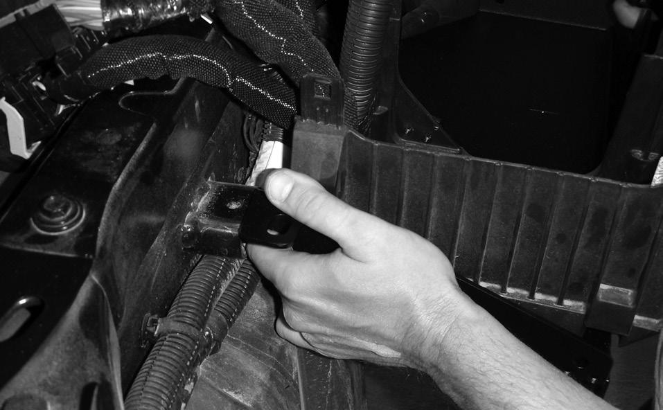
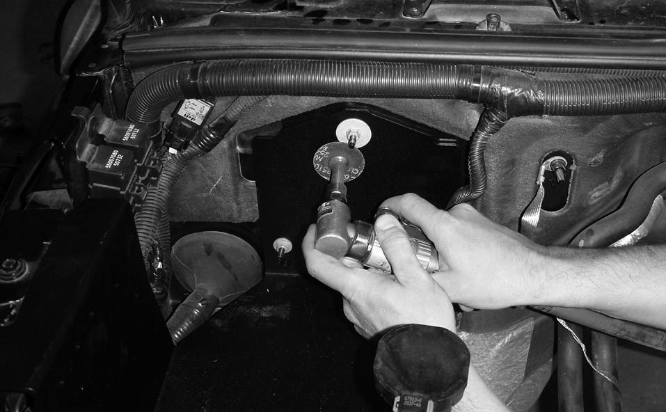
16 b. harness to body 1. Install the 10-way gray connector to the inside of the firewall using the double push-pin fastener included in the connector. 2. Install the C way connector to the firewall bracket like stock. 3. Route the harness over the AC Liquid line and around to the PCM/Computer. You can reuse the factory zip ties to fasten the harness to the washer bottle tray 4. Plug the harness into the AEV PCM and then into the AC Pressure Transducer. 5. Install the AEV 4-way Pigtail Harness into the PCM/Computer connector C3 (body side white) connector by releasing the terminal lock inside the connector (red slide.) Insert a very small allen wrench or similar tool into the backside of the cavities specified on the pigtail wires and with a small amount of force, break off the small plastic studs and poke them through the front of the connector. You may need a small needle nose pliers to remove the plastic studs from the connector. Once the cavities are clear, insert the wires until the terminal has a definite click into position. Once all the wires are inserted, activate the terminal lock and plug C3 into place. Reference photos Ground connect to PCM/Computer C3 13
17 14
18 15
 from the battery tray; disconnect the large 34 way (black) connector as shown. 3. Remove the tray from the vehicle. B. Install the new tray 1.")
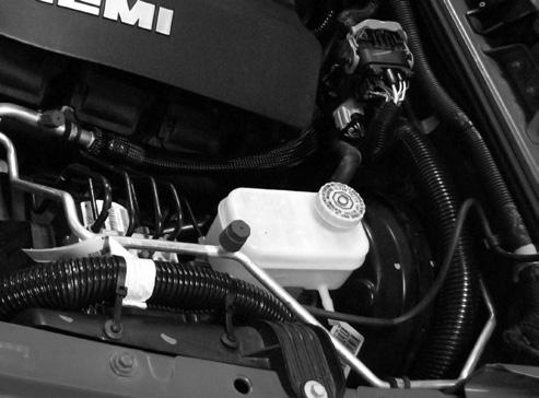
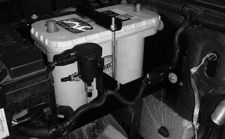
19 Part iv: battery tray a. remove the factory battery 1. Remove the factory air box, purge valve, and battery. 2. Release the TIPM (fuse block) from the battery tray; disconnect the large 34 way (black) connector as shown. 3. Remove the tray from the vehicle. B. Install the new tray 1. The new tray is a tight fit and there is only one way to install it without bending the mounting tabs. Place the new tray starting with the three bolts on the rear of the tray; try to slide the tray into place in the front of the vehicle using a motion that is horizontal, from the center of the vehicle outward. Use the factory bolts to fasten the tray into position. 2. Remove the TIPM bracket and the speed nuts from the original tray, re-use this hardware on the AEV tray and re-mount the TIPM and 34 way connector. 3. Trim the studs on the firewall using a cut-off wheel. 4. Install the battery as shown using the included bracket, J-bolt and nut. 5. Mount the purge valve and rearrange the hoses as shown. C. 5.7L, 6.1L, & 6.4L air filter bracket 1. Using the filter bracket supplied with the HEMI kit, mount the bracket to the front of the battery tray and to the front of the vehicle as shown Install the bolts from inside the battery tray outward. 2. Mount the supplied K&N air filter to the bracket (K&M #RC-4630) 16


20 D. 3.8L air box mounting 1. Mount the included brackets as shown to the front of the AEV Battery Tray. Install the bolts from inside the battery tray outward. 2. Remove the stock rubber air box isolators from the original tray and reuse them in the supplied brackets. 3. Mount the stock air box. 17
21 18
22 19
23 20
24 21

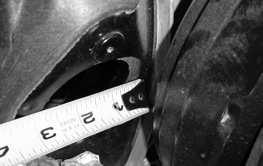
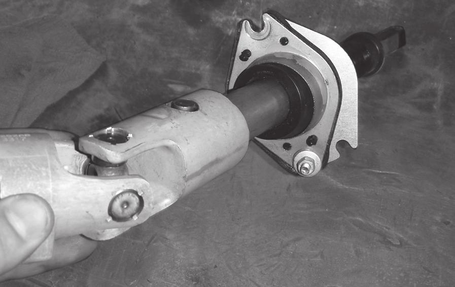
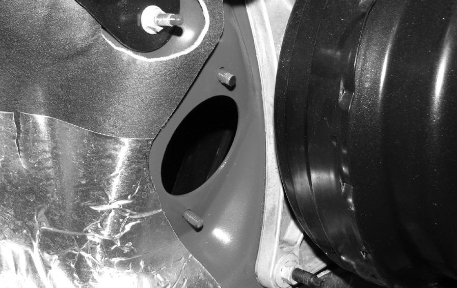
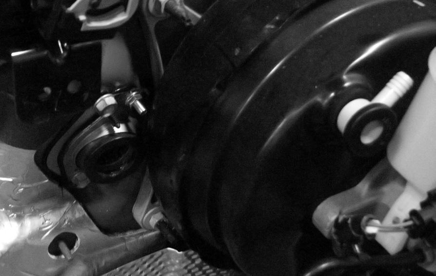
25 Part v: STEERING SHAFT RELOCATION In order to provide ample clearance between the steering shaft, ignition coils, and valve cover, a relocation bracket is provided. The use of a die grinder is required. If you are not familiar with JK systems, please reference the Jeep Service Manual available at any Chrysler dealer. 1. From inside the vehicle, remove the upper intermediate shaft. Be sure that the steering wheel is secured to prevent rotation so that the clock spring is not broken. 2. From the engine side of the firewall, mark a cut line as shown (Figure 3.) You will need to open the hole in the firewall up approximately 9/16 at the arc s maximum. 3. Using a die grinder or similar tool cut the crescent shape to enlarge the hole (Figure 4.) Use touch up paint on the edge to prevent corrosion. 4. Fit the AEV steering relocation bracket to the firewall loosely, followed by the upper intermediate shaft. Using the supplied and stock hardware, tighten the bracket and shaft down while maintaining maximum offset for the shaft. Use a small bead of black silicone to seal the plate to the firewall. For Models: Steering relocation bracket will be placed on the engine side of the firewall. This will require trimming of the mounting studs. Refer to figures Check for clearance to the vacuum booster, there should be approximately 1/8 clearance. Fig. 1 22

26 Fig. 2 Fig. 3 23

27 Fig. 4 Fig. 5 24

28 Fig. 6 Fig. 7 25

29 Fig. 8 Fig. 9 26


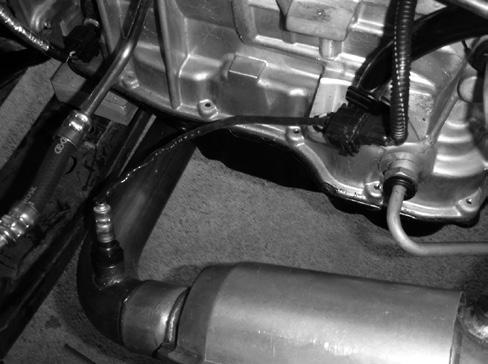
30 PART VI: PLUMBING A. AEV HEMI Fuel Line 1. Remove the locking clip out of the plastic fuel line at the tank as shown (fig. 1.) 2. Install the stud provided into the 5-45 transmission and reuse the steel fuel line bracket from the V6 engine (fig. 2.) 3. Install the AEV Fuel Line; be sure to lubricate all tubes or hoses prior to installation in order to avoid damaging seals (fig. 3.) fig. 1 fig. 2 fig. 3 27
 1.")
 fig.")
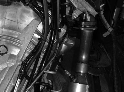
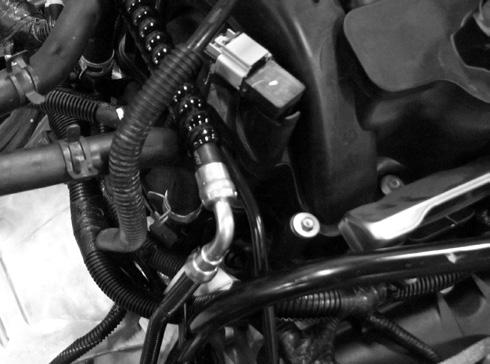
31 b. Power steering lines This step is to be performed after the powertrain has been installed. Be sure you are using the correct power steering pump (Mopar # AA.) 1. Install the lines as shown (fig. 4.) Be sure to lubricate all O-rings prior to assembly. 2. The two lines with push connect fittings attach to the stock trans cooler (fig. 5.) fig. 4 fig. 5 28

 onto the compressor using stock hardware. The firewall side will be installed when the body is mated to the chassis. 3.")
32 c. AEV AC Lines (body side) 1. Install the liquid line (Condenser to Firewall.) Use the stock hardware to connect the lines. 2. Fasten the line to the ground stud located on the left fender structure immediately behind the ABS module using the supplied clip. 3. Be sure to lubricate all O-rings prior to assembly. d. aev ac lines (powertrain side) 1. Reuse the 3.8L AC Compressor: Modification is required (see instructions in Overview Guide.) 2. Install the suction line (Compressor to Firewall) onto the compressor using stock hardware. The firewall side will be installed when the body is mated to the chassis. 3. Install the AC Discharge line (Compressor to Condenser) to the compressor using the stock hardware. Install the stock pressure transducer. The condenser side will be installed when the body is mated to the chassis. 4. Be sure to lubricate all O-rings prior to assembly. e. AEV transmission cooler 1. Install the transmission cooler to the AC condenser. Locate the cooler 3.5 from the top of the condenser and 3.5 from the right side of the condenser. Pre-install transmission cooler hose on each barb of the transmission cooler. 2. Using the Mopar AA Transmission Cooler lines, remove the OE hose portion (fig. 6) and flare the lines as shown (fig. 7) fig. 6 fig. 7 29

33 f. heater hoses Cut the stock 3.8L hoses as shown (fig. 8a) keeping the center sections. Fit these sections to the completed powertrain before mating the body to the chassis (fig. 8b.) fig. 8a fig. 8b g. evaporative purge valve hoses 1. Reuse the stock 3.8L hose from the fuel tank to the purge valve. Attach this line to the fuel line using the stock bracket and a couple zip ties. 2. Use Mopar part # AA hose to go from the intake, around the engine to the purge valve. This hose doesn t quite go all the way to the purge valve; you will need to use a portion of the stock 3.8L purge valve line from the purge valve to the engine. 30

34 h. radiator hoses 1. Install the lower radiator hose as shown (fig. 9.) 2. Fan shroud may need to be trimmed to ensure proper clearance from radiator hose. fig. 9 31

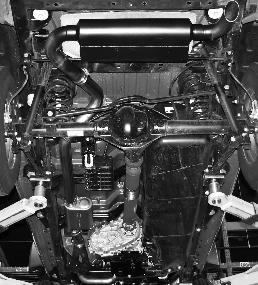
35 Part vii: exhaust AEV s HEMI exhaust is designed specifically for the 5.7L HEMI but can be used for 6.1L and 6.4L engines as long as the 5.7L manifolds, gaskets, and bolts are used. The exhaust is designed around the stock suspension and bumpers and may need to be modified to accommodate aftermarket suspensions, bumpers, or other accessories. DO NOT TIGHTEN ANY PART OF THE EXHAUST SYSTEM UNTIL THE FINAL DESIRED FIT IS ACHIEVED! 1. Install the hanger mount into the existing cross member hole behind the transfer case. 2. Adjust for clearances paying particular attention to the area around the front driveshaft, JK cross member, transmission pan, rear trackbar, and rear bumper. 3. The right hand down that goes under the transmission oil pan should be parallel with JK cross member when fitted properly. 4. You may wish to tack weld all joints for increased durability. 5. Install the star washers on the four isolator hangers. 6. Refer to the included photos for placement of exhaust pieces. 32
36 33
37 VIII. procal MODULE Programming. Please refer to the User Guide and Quick Reference Guide that came with your ProCal for correct programming procedure. Throttle Tolerance Programming This mode allows the user to program throttle tolerance and effectively pair a PCM and pedal. When a new PCM or pedal has been installed, the previous values stored in the PCM may not match the specific tolerance of the pedal and need to be reprogrammed Notes: This mode requires simultaneous inputs from a user on the throttle pedal as well as the multifunction light stalk. When programming, follow the steps in a deliberate, but not rushed manner. The entire process should take approximately 3 4 seconds. If the process is completed either too fast or too slow, the pairing will fail. Procedure: Set the DIP switches as shown below. With the engine off and ignition on, plug the module into the OBD port and follow the steps below: 1. When the module is ready, the Electronic Throttle (ETC) Indicator (a lightning bolt surrounded by two vertical lines) will flash on the dash. 2. To start the pedal routine, pull the headlight stalk back into the Highbeam Flash position, then release the headlight stalk allowing it to fall back into the Highbeam Off position. The routine has now started. 3. Press and hold the pedal all the way to the floor. 4. Move the headlight stalk forward to the Highbeam On position. 5. Release the pedal completely. 6. Move the headlight stalk back to the Highbeam Off position. 7. The routine is now completed. 8. Turn the ignition OFF, wait, then start the engine. Test the pedal and verify that it is functioning properly. If not, repeat steps
38 axle ratio programming Using the ProCal Module to program axle ratio once your new HEMI engine is installed requires a special mode. Programming axle ratio is required after completing your HEMI conversion even if you did not change your axle gear ratio. There is no performance increase by adjusting this value to anything besides what the vehicle has physically installed. Failure to program the axle gear ratio or programming the incorrect ratio will cause some vehicles to go into Limp-In mode. 1. Set the first 3 DIP switches as shown. 2. Set switches 4 and 5 as shown. 5.7 L 6.4 L 3. Set the remaining switches based on the chart. Once all the dip switches are set, please refer to the User Guide that came with your ProCal Module for the proper programming procedure. tire size programming You may now use the ProCal Module to program your tire size. Please use the Quick Reference Guide and User Guide that came with your ProCal Module for the proper programming procedure. 35
JK V8 HEMI BUILDER KIT Overview
 JK V8 HEMI BUILDER KIT Overview Installation Guide 5.7L & 6.1L HEMI 2007-2008 JK - SWB, LWB Page 1 of 1 Congratulations on purchasing your AEV HEMI JK Installation kit. These instructions have been written
AEV30243AJ Last Updated: 11/14/17. 3 Dualsport front suspension ram truck 2500/3500 INSTALLATION GUIDE
 AEV30243AJ Last Updated: 11/14/17 3 Dualsport front suspension ram truck 2500/3500 INSTALLATION GUIDE PLEASE READ BEFORE YOU START TO GUARANTEE A QUALITY INSTALLATION, WE RECOMMEND READING THESE INSTRUCTIONS
AEV30213AF Last Updated: 05/24/18. jk wrangler dualsport sc suspension right hand drive INSTALLATION GUIDE
 AEV30213AF Last Updated: 05/24/18 jk wrangler 3.5 4.5 dualsport sc suspension right hand drive INSTALLATION GUIDE PLEASE READ BEFORE YOU START TO GUARANTEE A QUALITY INSTALLATION, WE RECOMMEND READING
AEV30213AH Last Updated: 04/28/17. jk wrangler dualsport sc suspension INSTALLATION GUIDE
 AEV30213AH Last Updated: 04/28/17 jk wrangler 3.5 4.5 dualsport sc suspension INSTALLATION GUIDE PLEASE READ BEFORE YOU START TO GUARANTEE A QUALITY INSTALLATION, WE RECOMMEND READING THESE INSTRUCTIONS
AEV30243AK Last Updated: 05/01/18. 3 Dualsport front suspension ram truck 2500/3500 INSTALLATION GUIDE
 AEV30243AK Last Updated: 05/01/18 3 Dualsport front suspension ram truck 2500/3500 INSTALLATION GUIDE PLEASE READ BEFORE YOU START TO GUARANTEE A QUALITY INSTALLATION, WE RECOMMEND READING THESE INSTRUCTIONS
Procharger Stage II Intercooled Supercharger System (11-14 GT)
") Procharger Stage II Intercooled Supercharger System (11-14 GT) Installation Time: Approximately one day. Installed on 2012 Mustang GT 5.0/Manual Required Tools 3/8 Socket Set (Standard and Metric) 1/2
Procharger Stage II Intercooled Supercharger System (11-14 GT) Installation Time: Approximately one day. Installed on 2012 Mustang GT 5.0/Manual Required Tools 3/8 Socket Set (Standard and Metric) 1/2
Instant Chat off the main page of Or simply call our tech team at
 FRONT MOUNT INTERCOOLER 2015+ WRX 2017-07-07 Thank you for purchasing this PERRIN product for your car! Installation of this product should only be performed by persons experienced with installation of
INSTALLATION GUIDE. 3 Dualsport suspension. ram truck 2500/3500. AEV30243AA Last Updated: 04/10/15
 3 Dualsport suspension AEV30243AA Last Updated: 04/10/15 ram truck 2500/3500 INSTALLATION GUIDE PLEASE READ BEFORE YOU START TO GUARANTEE A QUALITY INSTALLATION, WE RECOMMEND READING THESE INSTRUCTIONS
INSTALLATION GUIDE. High Steer Kit
 AEV30212AE Last Updated: 12/09/16 High Steer Kit Designed for 2007 current Jeep JK Wrangler and Wrangler Unlimited models in all trim levels, including Rubicon, with at least 3.0 of suspension lift. INSTALLATION
AEV30207AA Last Updated: 2/14/ Dualsport xt suspension INSTALLATION GUIDE
 AEV30207AA Last Updated: 2/14/12 2.5 Dualsport xt suspension INSTALLATION GUIDE PLEASE READ BEFORE YOU START TO GUARANTEE A QUALITY INSTALLATION, WE RECOMMEND READING THESE INSTRUCTIONS THOROUGHLY BEFORE
Step 6: Remove and save the MAP sensor for later use. Step 7: Remove the passenger side intercooler pipe and the EGR intake manifold.
 LBZ Twin kit Install Step 1: Disconnect both batteries. Step 2: Drain coolant and oil also remove passenger side inner fender. Step 3: Remove intake box and piping. (Remove and save the MAF sensor in the
97-02 JEEP TJ BODY LIFT KIT INSTRUCTIONS
 92RC60500 97-02 JEEP TJ BODY LIFT KIT INSTRUCTIONS Congratulations on your purchase of a new Rough Country 2 /3 Body Lift. We are committed to providing you with the best product available for the best
PREMIUM FRONT BUMPER FOR RAM 2500/3500. AEV30239AJ Last Updated: 09/05/17 INSTALLATION GUIDE
 PREMIUM FRONT BUMPER FOR RAM 2500/3500 AEV30239AJ Last Updated: 09/05/17 INSTALLATION GUIDE PLEASE READ BEFORE YOU START TO GUARANTEE A QUALITY INSTALLATION, WE RECOMMEND READING THESE INSTRUCTIONS THOROUGHLY
09-12 Dodge 4WD /4 Body Lift
 92RC80000 09-12 Dodge 4WD 1500 1 1/4 Body Lift Thank you for choosing Rough Country for all your suspension needs. Rough Country recommends a certified technician install this kit. Attempts to install
JEEP CHEROKEE, WAGONEER (XJ) FRONT BUMPER INSTALLATION INSTRUCTIONS KIT# W/ WINCH KIT# 83203
 FRONT BUMPER INSTALLATION INSTRUCTIONS KIT# W/ WINCH KIT# 83203") 3651 N Highway 89 Chino Valley, AZ 86323 (928) 636-7080 www.p-a-g.net JEEP CHEROKEE, WAGONEER (XJ) FRONT BUMPER INSTALLATION INSTRUCTIONS 1984-2001 KIT# 83202 1984-2001 W/ WINCH KIT# 83203 WARNING Before
3651 N Highway 89 Chino Valley, AZ 86323 (928) 636-7080 www.p-a-g.net JEEP CHEROKEE, WAGONEER (XJ) FRONT BUMPER INSTALLATION INSTRUCTIONS 1984-2001 KIT# 83202 1984-2001 W/ WINCH KIT# 83203 WARNING Before
HASPORT PERFORMANCE EFH1
 HASPORT PERFORMANCE Installation Instructions For: Part Number EFH1 1988-1991 Honda Civic/CRX Hasport Performance mounts are the result of extensive research and engineering. All mounts are designed with
07-11 GM 4WD 1500 P/U 1 1/4 Body Lift
 92RC70100 07-11 GM 4WD 1500 P/U 1 1/4 Body Lift Thank you for choosing Rough Country for all your suspension needs. Rough Country recommends a certified technician install this kit. Attempts to install
05-08 GT. Hellion Power Systems Mustang Kit Instructions
 Hellion Power Systems 05-08 Mustang Kit Instructions 1. Disconnect Battery 2. Drain Radiator, keep fluid for re-installation. 3. Remove air box and inlethoses. 6. Next, underneath, punch oil pan for turbo
PRODUCT USE INFORMATION
 9RC61000 Jeep YJ Body Lift Thank you for choosing Rough Country for all your suspension needs. This body lift fits both manual and Automatic equipped vehicles!!! Refer to last page of this Instruction
3 Dualsport rear suspension ram truck 2500 AIR RIDE. AEV30262AA Last Updated: 07/11/17 INSTALLATION GUIDE
 3 Dualsport rear suspension ram truck 2500 AIR RIDE AEV30262AA Last Updated: 07/11/17 INSTALLATION GUIDE PLEASE READ BEFORE YOU START TO GUARANTEE A QUALITY INSTALLATION, WE RECOMMEND READING THESE INSTRUCTIONS
ADVANCE ADAPTERS INC. P/N: VORTEC GEN. III V8 SQ. BOLT TJ WRANGLER MOTOR MOUNTS (WITH A/C)
") Paso Robles, CA 93447 PAGE 1 OF 6 Telephone: (800) 350-2223 Fax: (805) 238-4201 Page Rev. Date: 04-16-14 KIT CONSISTS OF: No. Qty Part No. Description 1. 2 713092A BOLT SLEEVE 2. 4 713092B GEN 3 MOTOR
Paso Robles, CA 93447 PAGE 1 OF 6 Telephone: (800) 350-2223 Fax: (805) 238-4201 Page Rev. Date: 04-16-14 KIT CONSISTS OF: No. Qty Part No. Description 1. 2 713092A BOLT SLEEVE 2. 4 713092B GEN 3 MOTOR
INSTALLATION INSTRUCTIONS 97 FORD EXPEDITION
 INSTALLATION INSTRUCTIONS 97 FORD EXPEDITION 1. Read the instructions completely and carefully before you begin. Check the kit for proper contents (refer to the part s list and the picture diagrams). Before
NISSAN FRONTIER 2 & 4WD AUTOMATIC & MANUAL TRANS. KING & CREW CAB MODELS 3 BODY LIFT KIT INSTALLATION INSTRUCTIONS KIT# 40083
 3651 N Highway 89 Chino Valley, AZ 86323 (928) 636-7080 www.p-a-g.net NISSAN FRONTIER 2 & 4WD AUTOMATIC & MANUAL TRANS. KING & CREW CAB MODELS 3 BODY LIFT KIT INSTALLATION INSTRUCTIONS 2005-2011 KIT# 40083
DODGE DAKOTA 3 BODY LIFT INSTALLATION INSTRUCTIONS KIT # 60153
 DODGE DAKOTA 3 BODY LIFT INSTALLATION INSTRUCTIONS 2003-04 KIT # 60153 Installation of a Performance Automotive Group body lift kit will change the vehicle s center of gravity and handling characteristics
AEV30308AA Last Updated: 05/31/18. 4 DUALSPORT sc SUSPENSION system for RAM 1500 air ride standard and rebel INSTALLATION GUIDE
 AEV30308AA Last Updated: 05/31/18 4 DUALSPORT sc SUSPENSION system for RAM 1500 air ride standard and rebel INSTALLATION GUIDE PLEASE READ BEFORE YOU START TO GUARANTEE A QUALITY INSTALLATION, WE RECOMMEND
IAG Street Series Air / Oil Separator (AOS) For WRX
 For WRX") P IAG Street Series Air / Oil Separator (AOS) For 2015-16 WRX Part# IAG-ENG-7152 Tools Required: Ratchet, torque wrench, extensions, needle nose pliers, hose cutter, snips/scissors, flat head screw driver,
P IAG Street Series Air / Oil Separator (AOS) For 2015-16 WRX Part# IAG-ENG-7152 Tools Required: Ratchet, torque wrench, extensions, needle nose pliers, hose cutter, snips/scissors, flat head screw driver,
BLACKBIRD INSTALLATION SUPPLEMENT
 BLACKBIRD INSTALLATION SUPPLEMENT FOR 2003-7 FORD 6.0 LITER DIESEL SINGLE ALTERNATOR F-350, F-450, F-550, EXCURSION VERSION 7-07 Parts Description Blackbird Wiring Manual Installation Supplement 6.0 Liter
Installation Instructions For: Part Number EFK1 K-series Mount Kit for Civic and CR-X
 HASPORT PERFORMANCE Installation Instructions For: Part Number EFK1 K-series Mount Kit for 1988 1991 Civic and CR-X HASPORT PERFORMANCE Inc. 2849 S. 44 th St. Phoenix, AZ 85040 Phone: (602) 470-0065 Fax:
MAZDASPEED3 Intercooler Instructions
 MAZDASPEED3 Intercooler Instructions Congratulations on your purchase of the COBB Tuning Front Mount Intercooler System for your 2007-2009 Mazdaspeed3. The following instructions should assist you through
Disconnect negative battery cable and remove coolant bottle cap.
 1 of 16 3/25/2012 10:18 AM ools Required SA9105E 3-Bar Engine Support Fixture SA9412G Constant Force Clamp Pliers SA9127E Gage Bar Set Powertrain Assembly Removal Caution: Do not allow smoking or the use
INSTALLATION GUIDE. 2.0 Spacer. suspension system. AEV30211AE Last Updated: 11/06/14
 AEV30211AE Last Updated: 11/06/14 2.0 Spacer suspension system INSTALLATION GUIDE PLEASE READ BEFORE YOU START TO GUARANTEE A QUALITY INSTALLATION, WE RECOMMEND READING THESE INSTRUCTIONS THOROUGHLY BEFORE
JEEP WRANGLER (TJ), UNLIMITED (TJL), RUBICON MODELS BODY LIFT KIT INSTALLATION INSTRUCTIONS KIT# KIT# 973
, UNLIMITED (TJL), RUBICON MODELS BODY LIFT KIT INSTALLATION INSTRUCTIONS KIT# KIT# 973") JEEP WRANGLER (TJ), UNLIMITED (TJL), RUBICON MODELS BODY LIFT KIT INSTALLATION INSTRUCTIONS 1997-2006 2 KIT# 972 3 KIT# 973 WARNING Installation of a Performance Automotive Group body lift will change
JEEP WRANGLER (TJ), UNLIMITED (TJL), RUBICON MODELS BODY LIFT KIT INSTALLATION INSTRUCTIONS 1997-2006 2 KIT# 972 3 KIT# 973 WARNING Installation of a Performance Automotive Group body lift will change
IAG Competition Series Air / Oil Separator (AOS) For WRX
 For WRX") P IAG Competition Series Air / Oil Separator (AOS) For 2015-16 WRX Part# IAG-ENG-7252 Tools Required: Ratchet, torque wrench, extensions, needle nose pliers, hose cutter, snips/scissors, flat head screw
P IAG Competition Series Air / Oil Separator (AOS) For 2015-16 WRX Part# IAG-ENG-7252 Tools Required: Ratchet, torque wrench, extensions, needle nose pliers, hose cutter, snips/scissors, flat head screw
LPE C5 Battery Relocation Kit
 LPE C5 Battery Relocation Kit The LPE C5 Corvette battery relocation kit improves vehicle weight distribution by moving weight to the rear of the vehicle. The improved weight distribution increases traction
»Product» Safety Warning
 #J9210 Installation Instructions 2007-13 Jeep Wrangler JK 2" Body Lift Kit Read and understand all instructions and warnings prior to installation of product and operation of vehicle. Zone Offroad Products
09-12 Dodge 4WD Leveling Kit
 9235900 09-12 Dodge 4WD 1500 2.5 Leveling Kit Thank you for choosing Rough Country for all your suspension needs. DOES NOT FIT TRX PACKAGE VEHICLES!! Rough Country recommends a certified technician install
Revised 10/22/2014 Page 2 of?
 1.Remove side panels, hood, seat, fuel tank, and 2.Remove stock air box, remove fuel line muffler. Save exhaust springs and rubber muffler mounts for turbo bracket. Sand back surface flat for mounting.
Installation Instructions For: Part Number EGK Honda Civic, Del Sol & Integra
 HASPORT PERFORMANCE Installation Instructions For: Part Number EGK1 1992-1995 Honda Civic, 1993-1997 Del Sol & 1994-2001 Integra HASPORT PERFORMANCE Inc. 4046 East Winslow Ave. Phoenix, AZ 85040 Phone:
TOYOTA TUNDRA 3 BODY LIFT INSTALLATION INSTRUCTIONS 2014 KIT# 5643
 3651 N Highway 89 Chino Valley, AZ 86323 (928) 636-7080 www.p-a-g.net TOYOTA TUNDRA 3 BODY LIFT INSTALLATION INSTRUCTIONS 2014 KIT# 5643 Installation of a Performance Automotive Group body lift kit will
8 Zip Tie Zip Tie 1 Union Fitting 1 ½ ½ Union Reducer Fitting Union 1 5/8 ½ (For Plastic Intake Manifold Vehicles)
") P IAG Street Series Air / Oil Separator (AOS) For 2017 STI Part# IAG-ENG-7151 Tools Required: Ratchet, torque wrench, extensions, needle nose pliers, hose cutter, snips/scissors, flat head screw driver,
P IAG Street Series Air / Oil Separator (AOS) For 2017 STI Part# IAG-ENG-7151 Tools Required: Ratchet, torque wrench, extensions, needle nose pliers, hose cutter, snips/scissors, flat head screw driver,
Edelbrock E-Force Supercharger Part #1538: Dodge 1500 Truck 5.7L V8 HEMI
 Edelbrock E-Force Supercharger Part #1538: 2009-2014 Dodge 1500 Truck 5.7L V8 HEMI 2009-14 Dodge 5.7L Hemi 1500 Truck INTRODUCTION Thank you for purchasing the Edelbrock Supercharger System for the 2009-15
CHEVY AVALANCHE 1/2-TON ONLY 3 BODY LIFT KIT INSTALLATION INSTRUCTIONS KIT# 10173
 3651 N Highway 89 Chino Valley, AZ 86323 (928) 636-7080 www.p-a-g.net CHEVY AVALANCHE 1/2-TON ONLY 3 BODY LIFT KIT INSTALLATION INSTRUCTIONS 2003-2005 KIT# 10173 Installation of a Performance Automotive
INSTALLATION GUIDE. JK Rear bumper & tire carrier. AEV30105AC Last Updated: 10/11/16 US PATENT: D642,502 ; D
 AEV30105AC Last Updated: 10/11/16 JK Rear bumper & tire carrier US PATENT: D642,502 ; D633.024 INSTALLATION GUIDE PLEASE READ BEFORE YOU START TO GUARANTEE A QUALITY INSTALLATION, WE RECOMMEND READING
TURBOCHARGER L INSTALLATION GUIDE
 1 TURBOCHARGER INSTALLATION GUIDE TABLE OF CONTENTS Chapter Page 1 Intake and Cooling System Preparation 04 2 Intake Plenum and Manifold 08 3 Turbocharger Lubrication 11 4 Fuel Injectors 13 5 Re-installing
Installation Instructions
 2011-2013 LML DURAMAX COMPOUND-ADD 2011-2015 LML A Duramax TURBO KIT Add INSTALL A Turbo INSTRUCTIONS Compound Kit Installation Instructions 1-800-955-0476 - www.industrialinjection.com - info@industrialinjection.com
Ford 6.7 EGR Delete Kit
 Fits: 2011 12 Powerstroke 6.7L Read instructions thoroughly before proceeding! ***This kit may void factory warranty please check with manufacturer.*** ***This kit is intended for off road use only.***
I. Before starting installation
 5. Park the vehicle on a clean, dry, flat, level surface and block the tires so the vehicle cannot roll in either direction. A. Disconnect battery cables 1. Disconnect the negative cable first, then the
INSTALLATION GUIDE PREMIUM FRONT BUMPER FOR RAM AEV30304AA Last Updated: 09/18/17
 AEV30304AA Last Updated: 09/18/17 PREMIUM FRONT BUMPER FOR RAM 1500 INSTALLATION GUIDE PLEASE READ BEFORE YOU START To guarantee a quality installation, we recommend reading these instructions thoroughly
2015 Corvette Supercharger System Instructions
 2015 Corvette Supercharger System Instructions These instructions are meant to serve as a guide to the installation of the ECS 2015 Corvette Supercharging system. Please be sure to use all safety equipment
IAG Street Series Air / Oil Separator (AOS) For 2017 WRX
 For 2017 WRX") P IAG Street Series Air / Oil Separator (AOS) For 2017 WRX Part# IAG-ENG-7152 Tools Required: Ratchet, torque wrench, extensions, needle nose pliers, hose cutter, snips/scissors, flathead screwdriver,
P IAG Street Series Air / Oil Separator (AOS) For 2017 WRX Part# IAG-ENG-7152 Tools Required: Ratchet, torque wrench, extensions, needle nose pliers, hose cutter, snips/scissors, flathead screwdriver,
07-11 GM 1500 Pickup, Avalanche, Yukon, Tahoe, Suburban Front 2.5 Kit
 92130500 07-11 GM 1500 Pickup, Avalanche, Yukon, Tahoe, Suburban Front 2.5 Kit Thank you for choosing Rough Country for all your suspension needs. Rough Country recommends a certified technician install
4. Remove (4) 10mm and (1) 7mm bolt that holds fascia at front corners, on each side
 10mm and (1) 7mm bolt that holds fascia at front corners, on each side") 2010 Camaro LS3 1. Disconnect battery ground 2. Remove front wheels 3. Remove (5) push pins and (5) #20 torx screws on inner front wheel well liners and remove liners on each side 4. Remove (4) 10mm and
2010 Camaro LS3 1. Disconnect battery ground 2. Remove front wheels 3. Remove (5) push pins and (5) #20 torx screws on inner front wheel well liners and remove liners on each side 4. Remove (4) 10mm and
Always wear safety glasses when working on your vehicle.
 90-93 MAZDA MIATA SUPERCHARGER KIT The KraftWerks 90-93 Mazda Miata Supercharger Kit was designed for easy installation. Competent mechanics with the appropriate tools will find the process to be relatively
INSTALLATION MANUAL
 315000 INSTALLATION MANUAL EGR & Cooler Race Kit for 2015+ 6.7L Ford Powerstroke WARNING ONLY install this kit if you are using a tuner that disables the EGR sensors & circuit system. Any product that
Corvette Stage X Twin Turbo Installation. Please read the entire instructions as we ve made many changes.
 Corvette Stage X Twin Turbo Installation Please read the entire instructions as we ve made many changes. Disconnect battery. Remove plastic fuel rail covers over the valve cover. Remove Air Box in front
Subaru Front Mount Intercooler Kit STI Subaru Front Mount Intercooler Kit STI
 Subaru Front Mount Intercooler Kit STI 2008-2014 715500 Subaru Front Mount Intercooler Kit STI 2008-2014 Congratulations on your purchase of the Subaru Front Mount Intercooler Kit STI 2008-2014. The following
SL63 Weistec M156 Supercharger System Installation Guide Stage 1 / Stage 2
 SL63 Weistec M156 Supercharger System Installation Guide Stage 1 / Stage 2 WARNING! DO NOT HAVE YOUR ECU REPROGRAMMED ANYWHERE BUT AT WEISTEC FOR THIS SUPERCHARGER. THE AMG 63 USES AN ELECTRONIC THROTTLE
TOYOTA TACOMA 2 & 4WD AUTO & MANUAL TRANS W/O OEM TRAILER HITCH 3 BODY LIFT INSTALLATION INSTRUCTIONS KIT# 5603*
 3651 N Highway 89 Chino Valley, AZ 86323 (928) 636-7080 www.p-a-g.net TOYOTA TACOMA 2 & 4WD AUTO & MANUAL TRANS W/O OEM TRAILER HITCH 3 BODY LIFT INSTALLATION INSTRUCTIONS 2005-2015 KIT# 5603* *VEHICLES
NISSAN TITAN 3 BODY LIFT INSTALLATION INSTRUCTIONS KIT # 40053
 3651 N Highway 89 Chino Valley, AZ 86323 (928) 636-7080 NISSAN TITAN 3 BODY LIFT INSTALLATION INSTRUCTIONS 2004-2009 KIT # 40053 Installation of a Performance Automotive Group body lift kit will change
1963 GEN IV SUREFIT VINTAGE AIR CONDITIONING INSTALLATION
 by Randy Irwin 1963 GEN IV SUREFIT VINTAGE AIR CONDITIONING INSTALLATION Randy Irwin - Technical Writer Randy has been involved in the Chevy parts business for over 30 years. He is a wizard at creating,
IAG Competition Series Air / Oil Separator (AOS) For 2017 STI
 For 2017 STI") P IAG Competition Series Air / Oil Separator (AOS) For 2017 STI Part# IAG-ENG-7251 Tools Required: Ratchet, torque wrench, extensions, needle nose pliers, hose cutter, snips/scissors, flat head screw driver,
P IAG Competition Series Air / Oil Separator (AOS) For 2017 STI Part# IAG-ENG-7251 Tools Required: Ratchet, torque wrench, extensions, needle nose pliers, hose cutter, snips/scissors, flat head screw driver,
Parts List See cover Page
 Thank you for purchasing the CorkSport Front Mount Intercooler Kit for the 2010-2013 Mazdaspeed 3. Keep your BAT s under check with the CorkSport FMIC Kit with the small or large intercooler. Please let
Scion FR-S ZN6. GTX2867R Gen2 (Internal Wastegate) Installation Instructions GPP P/N #
 Installation Instructions GPP P/N #") TURBO KIT Scion FR-S ZN6 Subaru BRZ ZC6 GTX2867R Gen2 (Internal Wastegate) Installation Instructions GPP P/N # 11518000 Vehicle Type Chassis Code Engine Code Transmission Model Year Scion FR-S DBA-ZN6
TURBO KIT Scion FR-S ZN6 Subaru BRZ ZC6 GTX2867R Gen2 (Internal Wastegate) Installation Instructions GPP P/N # 11518000 Vehicle Type Chassis Code Engine Code Transmission Model Year Scion FR-S DBA-ZN6
PRXB EXHAUST BRAKE MAXIMUM EXHAUST FLOW DESIGN
 MAXIMUM EXHAUST FLOW DESIGN PRXB EXHAUST BRAKE C44072/C44073/C44074/C44075/C44076 APPLICATION: 994-2002 DODGE RAM TRUCKS W/5.9L CUMMINS DIESEL ENGINES WITH MANUAL & AUTOMATIC TRANSMISSIONS STOCK DODGE
DODGE RAM 2500/3500 (4WD) *HEMI ENGINE ONLY* (INCLUDING MEGA CAB) (EXCLUDING POWER WAGON) 3 BODY LIFT INSTALLATION INSTRUCTIONS KIT# 60223
 *HEMI ENGINE ONLY* (INCLUDING MEGA CAB) (EXCLUDING POWER WAGON) 3 BODY LIFT INSTALLATION INSTRUCTIONS KIT# 60223") 3651 N Highway 89 Chino Valley, AZ 86323 (928) 636-7080 www.p-a-g.net DODGE RAM 2500/3500 (4WD) *HEMI ENGINE ONLY* (INCLUDING MEGA CAB) (EXCLUDING POWER WAGON) 3 BODY LIFT INSTALLATION INSTRUCTIONS 2010-2012
3651 N Highway 89 Chino Valley, AZ 86323 (928) 636-7080 www.p-a-g.net DODGE RAM 2500/3500 (4WD) *HEMI ENGINE ONLY* (INCLUDING MEGA CAB) (EXCLUDING POWER WAGON) 3 BODY LIFT INSTALLATION INSTRUCTIONS 2010-2012
REMOVAL & INSTALLATION
 REMOVAL & INSTALLATION NOTE: For reassembly reference, label all electrical connectors, vacuum hoses and fuel lines before removal. Also place mating marks on engine hood and other major assemblies before
WD GM FRT 1.75 REAR LIFT KIT Thank you for choosing Rough Country for your suspension needs.
 921277N201 2007-13 4WD GM 1500 3.5 FRT 1.75 REAR LIFT KIT Thank you for choosing Rough Country for your suspension needs. Rough Country recommends a certified technician install this system. In addition
INSTALLATION INSTRUCTIONS DODGE DAKOTA 2 KIT # 682 (2WD), 692 (4WD) 3 KIT # 683 (2WD), 693 (4WD)
, 692 (4WD) 3 KIT # 683 (2WD), 693 (4WD)") INSTALLATION INSTRUCTIONS 1997-1999 DODGE DAKOTA 2 KIT # 682 (2WD), 692 (4WD) 3 KIT # 683 (2WD), 693 (4WD) Installation of a Performance Accessories body lift kit will change the vehicle s center of gravity
INSTALLATION INSTRUCTIONS 1997-1999 DODGE DAKOTA 2 KIT # 682 (2WD), 692 (4WD) 3 KIT # 683 (2WD), 693 (4WD) Installation of a Performance Accessories body lift kit will change the vehicle s center of gravity
SHELBY GT500
 2007-2009 SHELBY GT500 Removal of Factory Unit WARNING: 1. Radiator fluid must be handled properly. Please observe local ordinances with regards to handling and disposal. 2. Allow vehicle and components
C40008 & C40009 EXHAUST BRAKES
 EXHAUST BRAKES C40008 & C40009 1995 2003 Ford F250 / F350 7.3 L Powerstroke Diesel with manual transmissions 1995 1998 Ford F250 / F350 7.3 L Powerstroke Diesel with automatic transmission* *Requires the
7 th Gen. Celica GTS Turbo Kit Installation Guide This kit has not been CARB approved and is intended for racing / offroad purposes only.
 7 th Gen. Celica GTS Turbo Kit Installation Guide This kit has not been CARB approved and is intended for racing / offroad purposes only. The purpose of this guide is to serve as a reference for use when
FULL LENGTH HEADERS/ CATTED HEAD PIPES
 INSTALLATION INSTRUCTIONS INS232 2016-2018 CAMARO 6.2L V8 FULL LENGTH HEADERS/ CATTED HEAD PIPES Part #4044 and 40440 Special Tools required: 10mm, 12mm, 13mm, 15mm Socket and Wrenches, Pliers, Saw, Welder
4 December 2017 PN# , , Dodge 6.7L Rumble B SXE (I-00400) 1. BD Rumble B SXE. D o d g e 6. 7 L H P C R Installation Instructions
 1. BD Rumble B SXE. D o d g e 6. 7 L H P C R Installation Instructions") 4 December 2017 PN#1045705, 1045706, 1045708 Dodge 6.7L Rumble B SXE (I-00400) 1 DOWNLOAD ENHANCED INSTALL MANUALS AT dieselperformance.com BD Rumble B SXE D o d g e 6. 7 L H P C R Installation Instructions
4 December 2017 PN#1045705, 1045706, 1045708 Dodge 6.7L Rumble B SXE (I-00400) 1 DOWNLOAD ENHANCED INSTALL MANUALS AT dieselperformance.com BD Rumble B SXE D o d g e 6. 7 L H P C R Installation Instructions
Instant Chat off the main page of Or simply call our tech team at
 FRONT MOUNT INTERCOOLER 2008-13 STI 2014-04- 08 Thank you for purchasing this PERRIN product for your car! Installation of this product should only be performed by persons experienced with installation
DODGE DAKOTA 3 KIT INSTALLATION INSTRUCTIONS KIT# 60043
 DODGE DAKOTA 3 KIT INSTALLATION INSTRUCTIONS 2000-2002 KIT# 60043 Installation of a Performance Automotive Group body lift kit will change the vehicle s center of gravity and handling characteristics both
1 of 12 10/5/2015 8:11 AM
 1 of 12 10/5/2015 8:11 AM REMOVAL 1. Perform the fuel pressure release procedure See: Fuel Pressure Release > Procedures > Fuel System Pressure Release Procedure. 2. Recover the refrigerant from the refrigerant
PRXB EXHAUST BRAKE HIGH PERFORMANCE
 HIGH PERFORMANCE PRXB EXHAUST BRAKE C44059, C4406, C44063, C44065 APPLICATION 994-2002 DODGE RAM AUTOMATIC TRUCKS EQUIPPED WITH 47RE TRANSMISSIONS WITH 5.9L, 24 VALVE CUMMINS DIESEL ENGINES GETTING STARTED
AEV30229AD Last Updated: 06/17/14 REAR VISION SYSTEM INSTALLATION GUIDE
 AEV30229AD Last Updated: 06/17/14 REAR VISION SYSTEM INSTALLATION GUIDE PLEASE READ BEFORE YOU START TO GUARANTEE A QUALITY INSTALLATION, WE RECOMMEND READING THESE INSTRUCTIONS THOROUGHLY BEFORE BEGINNING
CHALLENGER TWIN TURBO SYSTEM INSTALLATION INSTRUCTIONS
 CHALLENGER TWIN TURBO SYSTEM INSTALLATION INSTRUCTIONS 1 Verify contents of kits with supplied packing list 1) Unhook the battery. 2) Remove wheel wells & front fascia of vehicle. 3) Remove the catalytic
FORD RANGER/SPLASH MAZDA B-SERIES (2&4WD, STANDARD & EXT. CAB) 3 BODY LIFT KIT INSTALLATION INSTRUCTIONS KIT# 853
 3 BODY LIFT KIT INSTALLATION INSTRUCTIONS KIT# 853") 3651 N Highway 89 Chino Valley, AZ 86323 (928) 636-7080 www.p-a-g.net FORD RANGER/SPLASH MAZDA B-SERIES (2&4WD, STANDARD & EXT. CAB) 3 BODY LIFT KIT INSTALLATION INSTRUCTIONS 1995-1997 KIT# 853 Installation
3651 N Highway 89 Chino Valley, AZ 86323 (928) 636-7080 www.p-a-g.net FORD RANGER/SPLASH MAZDA B-SERIES (2&4WD, STANDARD & EXT. CAB) 3 BODY LIFT KIT INSTALLATION INSTRUCTIONS 1995-1997 KIT# 853 Installation
TOYOTA TACOMA 2WD & 4WD 3 KIT INSTALLATION INSTRUCTIONS KIT# KIT# 5593
 3651 N Highway 89 Chino Valley, AZ 86323 (928) 636-7080 TOYOTA TACOMA 2WD & 4WD 3 KIT INSTALLATION INSTRUCTIONS 2001-2002 KIT# 5583 2003-2004 KIT# 5593 Installation of a Performance Automotive Group body
This information covers the proper procedure for replacing the Volvo D16F engine in a VT or VNL chassis.
 Volvo Trucks North America Greensboro, NC USA Engine, Replacement DService Bulletin Trucks Date Group No. Page 10.2007 210 139 1(47) Engine, Replacement Volvo D16F VNL, VT W2005773 This information covers
INSTRUCTIONS E36 SUPERCHARGER WITH C38 BLOWER.
 INSTRUCTIONS 1996-1999 E36 SUPERCHARGER WITH C38 BLOWER. 1 Introduction Congratulations on your purchase of an Active Autowerke Supercharger, and welcome to the AA Tuning family. Your supercharger kit
Jeep Wrangler TJ. Complete Air Conditioning System. Slide Control Head. Installation instructions
 WWW.JEEPAIR.COM 1996-1998 Jeep Wrangler TJ Complete Air Conditioning System Slide Control Head Installation instructions Kit Information After 1994 every vehicle was designed for R134a refrigerant. The
PRE-INSTALLATION. INSTALLATION INSTRUCTIONS Front Dodge Ram WD 6" Suspension Lift Kit
 2012-2015 Dodge Ram 1500 4WD 6" Suspension Lift Kit PRE-INSTALLATION 35015 2 - Knuckle (Driv/Pass) 2 - Crossmember (Front/Rear) 2 - Differential Bracket (Driv/Pass) 1 - Diff. Brace Bracket (Pass) 2 - Front
Sport S/T3 Suspension Installation Guide
 1 Sport S/T3 Suspension Installation Guide #1258250-JK 2-Door Sport S/T3 (No Shocks) #1258200-JK 2-Door Sport S/T3 (w/ Fox Shocks) #1258450-JK 4-Door Sport S/T3 (No Shocks) #1258400-JK 4-Door Sport S/T3
DODGE RAM 2500/3500 2WD *DIESEL ENGINE ONLY* (INCLUDING MEGA CAB) 3 BODY LIFT INSTALLATION INSTRUCTIONS KIT# PA60313
 3 BODY LIFT INSTALLATION INSTRUCTIONS KIT# PA60313") DO NOT combine suspension, body, or other lift devices. Use of vehicle with combined lifts may result in unsafe and/or unexpected handling characteristics. DODGE RAM 2500/3500 2WD *DIESEL ENGINE ONLY*
DO NOT combine suspension, body, or other lift devices. Use of vehicle with combined lifts may result in unsafe and/or unexpected handling characteristics. DODGE RAM 2500/3500 2WD *DIESEL ENGINE ONLY*
INSTALLATION INSTRUCTIONS AIR/OIL SEPARATOR KIT
 INSTALLATION INSTRUCTIONS AIR/OIL SEPARATOR KIT 2015+ SUBARU WRX (LHD ONLY) Document: 19-0136 Support: info@radiumauto.com This document covers the installation of the Radium brake master cylinder brace
BD TrackMaster S D o d g e H P C R Installation Instructions
 7 July 2016 PN#1045701, 1045702, 1045704 Dodge 6.7L TMS400 (I-00361) 1 BD TrackMaster S400 2008-2012 D o d g e H P C R Installation Instructions 1045701 2008-2009 Dodge 6.7L TMS400 1045702 2010-2012 Dodge
CLS63 Weistec M156 Supercharger System Installation Guide Stage 1 / Stage 2
 CLS63 Weistec M156 Supercharger System Installation Guide Stage 1 / Stage 2 WARNING! DO NOT HAVE YOUR ECU REPROGRAMMED ANYWHERE BUT AT WEISTEC FOR THIS SUPERCHARGER. THE AMG 63 USES AN ELECTRONIC THROTTLE
Powerstroke EGR Delete A B C
 20-203 6.7 Powerstroke EGR Delete A B C D E F G H I J K Part # A B C D E F G H I J K PACKING LIST: QTY. 3 5 2 Description Sensor Bracket Exhaust Blockoff Plate Straights Barbed Brass Fitting 39 5/8 Coolant
WARNING: ALWAYS relieve fuel pressure before disconnecting any fuel related component. DO NOT allow fuel to contact engine or electrical components.
 4.0L V8 - VINS [K,U] Selected Block 1990 Lexus LS 400 For Lextreme Powertrain 2020 S. Hacienda Blvd. # D Hacienda Heights California 91745 Copyright 1998 Mitchell Repair Information Company, LLC Friday,
8" 4-LINK SUSPENSION SYSTEM. Ford Super Duty 4WD Part#:
 Part#: 013813 8" 4-LINK SUSPENSION SYSTEM Ford Super Duty 4WD 2011-2016 Rev. 051817 491 W. Garfield Ave., Coldwater, MI 49036. Phone: 517-279-2135 E-mail: tech-bds@sporttruckusainc.com Read And Understand
FORD EXPLORER & MAZDA NAVAJO BODY LIFT KIT INSTALLATION INSTRUCTIONS KIT# KIT# 793
 3651 N Highway 89 Chino Valley, AZ 86323 (928) 636-7080 FORD EXPLORER & MAZDA NAVAJO BODY LIFT KIT INSTALLATION INSTRUCTIONS 1990-1994 2 KIT# 792 1990-1994 3 KIT# 793 Installation of a Performance Automotive
»Product» Safety Warning
 #C9315 Installation Instructions 2000-2005 Suburban/Tahoe/Yukon 1500 2/4wd 3" Body Lift Read and understand all instructions and warnings prior to installation of product and operation of vehicle. Zone
Edelbrock E-Force Supercharger JEEP WRANGLER JK 3.6L V6 Part #1527 and 15270
 Edelbrock E-Force Supercharger 2012-14 JEEP WRANGLER JK 3.6L V6 Part #1527 and 15270 INTRODUCTION Thank you for purchasing the Edelbrock Supercharger System for the Jeep Wrangler with 3.6L V6 Pentastar.
#TL T EA888 GEN 3 FUELING SYSTEM/ INSTALLATION INSTRUCTIONS
 #TL100069 2.0T EA888 GEN 3 FUELING SYSTEM/ INSTALLATION INSTRUCTIONS Notes: These instructions were written for a North American specification MkVII GTI. Other models, like the Golf R, are similar. When
ENGINE DEVELOPMENT INC.
 2003 Ford Expedition 4.6L& 5.4L We encourage you to read this manual thoroughly before you begin work, and perform the following: 1. A quick parts check to make certain your kit is complete. If you discover
Installation Instructions For: Part Number GDK20 for K20 engines and GDK24 for K24 engines into 2007 Honda Fit
 Installation Instructions For: Part Number GDK20 for K20 engines and GDK24 for K24 engines into 2007 Honda Fit Hasport Performance mounts are the result of extensive research and engineering. All mounts
DESTROKED. Circuits that will be run through the Ford PCM and Ford Engine Harness
 DESTROKED Thank you for your interest in Destroked. Please read through this overview to get a good idea of what is involved in your Cummins conversion project. Circuits that will be run through the Ford