Installation Manual P / P / P A / P B / P C E N G I N E B R A K E S
|
|
|
- Jessie Hampton
- 6 years ago
- Views:
Transcription
1 Manual A p p l i c a t i o n : D e t r o i t D i e s e l S e r i e s 6 0 P / P / P A / P B / P C E N G I N E B R A K E S
2


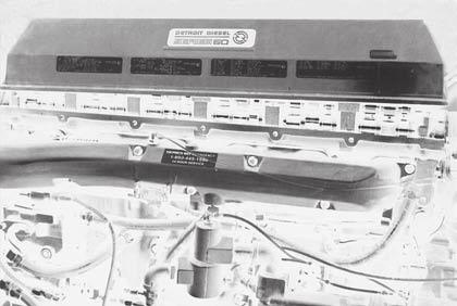
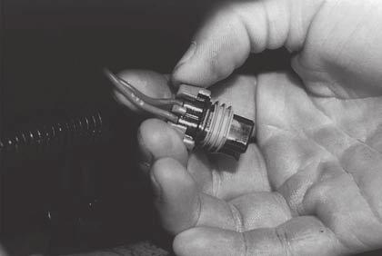
3 5 If the engine is equipped with an aluminum valve cover and base, both should be removed for easier and faster brake installation. NOTE: The valve cover base is originally installed with silicone adhesive on both sides of the camshaft caps. Take care not to stretch the gasket when removing the valve cover base. 1 E N G I N E N O T P R E W I R E D Remove the wiring harness mounting flange from the rear of the cylinder head. NOTE: Some engines may have engine brake wiring tied to the injector harness. If so, omit following steps 1 through There are four spare holes through the harness grommet which are sealed with plastic plugs. Pulling outward, remove any two of these plugs. 3 Insert both wires of the Pacbrake 'through head harness' through the grommet from the outside. NOTE: In trucks with limited access at the rear of the cylinder head, it may be easier to slide the grommet out of the head. 3
4


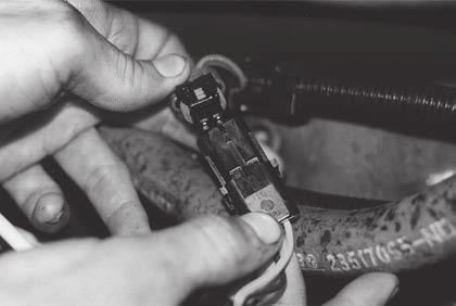
5 8 DDEC III and IV applications only: Remove the black protective cap and connect to Pacbrake harness previously installed in step 3. 9 The through head harness must now be connected to the under cover harness, P/N P As both halves of the connector are preassembled, simply insert the plain white wire into the hole on the same side as the other plain white wire. The remaining wires both have black shrink tube markings. 10 This connector is polarized and may now be parted and reconnected without losing correct brake sequencing. 11 DDEC II, III and IV applications: All injector electrical terminals on older engines should be bent upwards almost 90 O as shown to allow clearance for engine brake housings. 5


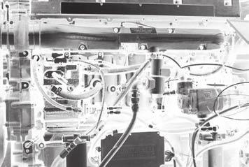
6 12 Later type terminals as shown require no modifications. 13 Secure the complete Pacbrake harness to the EUI harness with plastic ties. NOTE: Use only the ties supplied in the kit which are temperature stabilized and will not deteriorate due to heat. 1 B R A K E H O U S I N G I N S T A L L A T I O N Place the two spacer bars on the exhaust manifold side of the engine. CAUTION: Using air pressure, blow out the six mounting holes before placing the spacer bars. 2 Ensure that the OUT marks are adjacent to each other, and facing outwards. 6


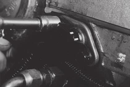
7 3 Our nylon connector should be positioned between cylinders 5 and 6. 4 Reposition the entire wiring harness to keep it from being chafed by the rocker levers or brake housings. If the original Detroit harness is long enough, it may be attached to the face but not the corner of the spacer bars. NOTE: Make certain that the three wires which will be attached to the solenoids are carefully positioned between cylinders 1-2, 3-4, and Move to the camshaft side of the engine. Remove the three outboard 12 pt. flange screws holding the camshaft bearing caps in locations #2, 4, and 6, as shown by the arrows. CAUTION: Using air pressure, blow out the three mounting holes. 6 Place a special hardened washer on each of the nine Pacbrake 12 pt. flange screws. 7


8 7 Carefully position the three engine brake housings on the engine. Lubricate and loosely install the nine flange screws and washers. 8 Run the flange screws down loosely using hand tools only. 9 Prior to initial tightening of the flange screws, make certain that the housings are pushed laterally (in the direction shown by the arrows) as far as each housing will go towards the exhaust manifold side of the engine. This action will precisely locate the Pacbrake pistons with their mating engine components. Snug down the flange screws. PUSH PUSH NOTE: The Pacbrake housings have a machined locating step on the single stud side, this aligns with the bearing cap for correct location above the exhaust valve adjusting screws. 10 Torque the three flange screws on the camshaft side, then the six on the exhaust manifold side to 40 ft. lbs. (55 Nm). Then repeat in the same sequence to 100 ft.lbs. (136 Nm). 8


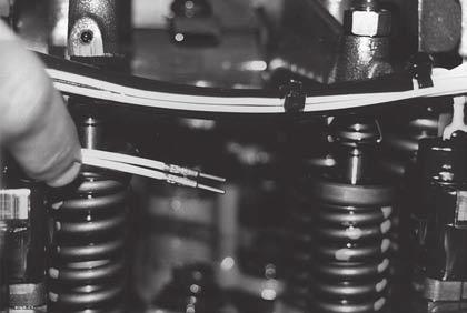
9 11 Attach the three wires to the solenoids. NOTE: A check should be done at this point if older style injector harness was used in previous step 11. Make certain injector terminals DO NOT contact Pacbrake housing, this will cause the engine to misfire. 1 S L A V E P I S T O N A D J U S T M E N T Loosen all twelve engine brake adjusting screws and locknuts. Determine which cylinders have clearance between exhaust rocker adjusting screws and valve stems, indicating that the exhaust valves are fully closed. There are usually four cylinders in this condition regardless of the crankshaft position. NOTE: Both screws on each cylinder having closed valves may be adjusted. 2 Slave lash may now be adjusted on all cylinders which have clearance between the exhaust rocker adjusting screw and valve stems. Turn the Paclash screw clockwise to establish zero exhaust valve lash. Once zero lash is determined, turn screw an additional 1/4 turn to squeeze out any trapped oil, then back screw out to zero lash. CAUTION: When adjusting the slave lash, the adjusting screw has a spring loaded piston, exercise caution as the piston in the adjusting screw must be collapsed when final adjustment is performed. 3 From this position (zero lash), turn the Allen wrench counterclockwise exactly 1/2 turn and torque the locknut to 25 ft. lbs. (35 N m). This method gives the correct slave piston clearance of.025". Repeat this procedure on all cylinders on which the exhaust valves are closed. Bar the engine over approximately one revolution and adjust the remaining cylinders which now have clearance between the exhaust rocker adjusting screw and valve stems. NOTE: Same procedures apply for all models. CAUTION: Do not overtorque slave adjusting screw locknut. Double check all torques and wiring prior to reinstalling the valve cover. Use silicone sealant at front and rear bearing caps at valve cover installation. Torque valve cover bolts as per DDC service manual. 9


10 1 C O N T R O L S Y S T E M D D E C I I Locate or drill a 1/2" or larger hole through the firewall. From the engine side of the firewall, pass the end of the harness with the four wires protruding, through the firewall and into the cab. Connect these and the power source to the dash switches as per the wiring schematic. For DDEC III and IV proceed to page Install the standard or optional clutch switch and adjust it so the circuit will be broken within the first inch of free travel of the clutch pedal. NOTE: For vehicles having automatic transmissions, please consult the Pacbrake factory. 3 Route the harness coming from the dash switches close by the clutch switch. Pull a short loop of green wire from the conduit. 4 Cut the wire and crimp on the two push-on terminals provided. Tape the conduit closed where the wires exit and attach to the clutch switch. 10


11 5 Mount the relay receptacle in any convenient position on the firewall, using the special drill point self-tapping screw supplied. NOTE: Ensure that the harness enters the bottom of the receptacle, to prevent moisture entering the relay. 6 Install the special relay into the receptacle. CAUTION: Do not substitute with any other relay, as the Pacbrake P60045 relay has a built-in diode to protect the DDEC system. 7 Install on/off switch and three-position switch in dash, conveniently located for the driver. 8 Continue the harness to the rear of the cylinder head and snap the two mating Weather Pack connectors together. 11
.")


12 9 This leaves one remaining white wire at the end of the harness, which must be connected to the #508 wire in the vehicle harness. This wire originates at terminal A-1 of the Electronic Control Module (ECM). 10 The ECM is mounted on the left side of the engine block, and #508 wire will be the uppermost one closest to the engine. 11 Cut the #508 wire where accessible and join the end originating at the ECM to our white wire with the attached butt connector. This should be crimped, Then shrunk down using a heat gun or other source, to produce a tightly sealed joint. NOTE: The remaining end of the #508 wire should be taped out of the way, as it dead-ends in the vehicle harness and will not be used. 12
13 D D E C I I W I R I N G S C H E M A T I C Hi-Med-Low Switch On-Off Switch Green Red Yellow Blue Fuse Ignition NOTE: Part conduit, pull a 6" loop of green wire from the dash end and apply two terminals then attach to clutch switch. Green Clutch Switch Relay Receptacle White To #508 wire Weather Pack Connector Under the cover


14 1 Some DDEC III and IV engines have the Pacbrake wiring installed at the factory. If not - follow the instructions below. Installations using kit P60154 follow the electrical instruction provided in the kit. CONTROL SYSTEM DDEC III-IV Locate the 30 pin connector at the rear end of the DDEC III or DDEC IV ECM. This is the Vehicle Interface Harness (VIH). NOTE: Some DDEC III and IV engines may not have the ECM programmed for engine braking. This may be verified using a Diagnostic Data Reader. If any of the ECM input switches; K2, K3, S3 or T3 read NONE, then the vehicle should be taken to a DDC dealer to have these switches enabled. 2 Note the color and/or number of the two wires originating at the K2 and K3 terminals of the VIH connector. They are both on the top row, K2 is in the center and K3 is the closest one to the engine. These two wires terminate behind the dash and may be grouped with a third wire connected to battery ground. 3 Mount the two dash switches and connect the three wires as shown in the DDEC III wiring schematic. CAUTION: Ensure that ONLY the negative ground side of the electrical system is input to terminals K2 and K3 via the dash switches OR DAMAGES TO THE ENGINE ECM WILL RESULT. 14
15 D D E C I I I - I V W I R I N G S C H E M A T I C Hi-Med-Low Switch On-Off Switch Jumper wire and terminals (3) supplied To K2 terminal Battery Ground To K3 terminal NOTES: One of the features of the DDEC III control system provides a progressive brake feature which is used when the vehicle is in cruise control. 30 pin connector The level of engine brake (low, med., high) selected via the dash switches will be the maximum amount of engine brake the ECM allows. Electronic Control Module (ECM) Also, using the foot brake or clutch during this procedure disables cruise control and progressive engine brake feature. Metri-Pack Connector Under the cover 15
16 Pacbrake Company toll-free: phone: fax: Internet: Canada: Ave. Surrey BC V4N 4C3 USA: 250 H St. Box 1822 Blaine WA Pacbrake P-61 and P-63A engine brakes are protected by law. U.S. patents 4,655,178 / 4,898,128 / 5,036,810. Pacbrake is a registered trademark of Pacbrake Company. Other trademarks used herein are property of their respective holders. Printed in Canada L
-!.5!, P-80 And P-80A )NSTALLATION %. ' ). % 0 $ETROIT 0! $ETROIT
NSTALLATION %. ' ). % 0 $ETROIT 0! $ETROIT") P-80 And P-80A VERY IMPORTANT APPLICATION INFORMATION Please read carefully as incorrect application will cause engine damage. 1 Before Starting Use the following information to determine the correct Pacbrake
P-80 And P-80A VERY IMPORTANT APPLICATION INFORMATION Please read carefully as incorrect application will cause engine damage. 1 Before Starting Use the following information to determine the correct Pacbrake
ENGINE BRAKE. Designed for Cummins N-14 Plus Engines with the following engine CPL # s
 MANUAL ENGINE BRAKE Designed for Cummins N-14 Plus Engines with the following engine CPL # s CPL 2025 N-14 435 ESP PLUS CPL 2026 N-14 370 ESP PLUS CPL 2390 N-14 370 ESP PLUS CPL 2391 N-14 435 ESP PLUS
ENGINE BRAKES. Application: CATERPILLAR 3406E C-15/C-16 ENGINES
 P-39/P-39A/P-39B/P-39D/P-39E ENGINE BRAKES Application: CATERPILLAR 3406E C-15/C-16 ENGINES GETTING STARTED This manual covers the installation and wiring instructions for the Caterpillar 3406E, C-15/C-16
Getting Started. INLINE MOUNT Exhaust Brakes. Thank you and congratulations on your purchase of a Pacbrake Inline Mount exhaust brake kit.
 Getting Started Thank you and congratulations on your purchase of a Pacbrake Inline Mount exhaust brake kit. Before starting, be sure you have attained the proper brake, mounting kit and control group
C FORD F250 / F L POWERSTROKE DIESEL WITH AUTOMATIC TRANSMISSIONS ONLY
 EXHAUST BRAKES C40019 1999-2003 FORD F250 / F350 7.3L POWERSTROKE DIESEL WITH AUTOMATIC TRANSMISSIONS ONLY Getting Started Thank you and congratulations on your purchase of a Pacbrake exhaust retarder.
C40008 & C40009 EXHAUST BRAKES
 EXHAUST BRAKES C40008 & C40009 1995 2003 Ford F250 / F350 7.3 L Powerstroke Diesel with manual transmissions 1995 1998 Ford F250 / F350 7.3 L Powerstroke Diesel with automatic transmission* *Requires the
E X H A U S T B R A K E S. APPLICATION: International Trucks 2000 Model Year & Newer With Multi-Plex Wiring 4200/4300/4400/7300/7400/7500/8500/8600
 MANUAL Direct Mount E X H A U S T B R A K E S APPLICATION: International Trucks 2000 Model Year & Newer With Multi-Plex Wiring 4200/4300/4400/7300/7400/7500/8500/8600 DT466/DT530/HT530 Engines (2000 MY
DirectMount EXHAUST BRAKES
 DirectMount EXHAUST BRAKES APPLICATION: Fixed Orifice and PRXB Exhaust Brakes 2003 2005 Dodge Trucks with 3.5" & 4" Exhaust and 47RE & 48RE Automatic Transmissions Only Vehicles with an existing air compressor
AIR INTAKE EMERGENCY SHUT-OFF VALVE PH2 C50204 AIR INTAKE SHUT-OFF VALVE DODGE 6.7L CUMMINS.
 AIR INTAKE EMERGENCY SHUT-OFF VALVE PH2 C50204 AIR INTAKE SHUT-OFF VALVE 2013-2017 DODGE 6.7L CUMMINS www.powerhalt.com Thank you for your purchase of a PowerHalt Air Intake Emergency Shut-Off Valve by
PRXB EXHAUST BRAKE MAXIMUM EXHAUST FLOW DESIGN
 MAXIMUM EXHAUST FLOW DESIGN PRXB EXHAUST BRAKE C44072/C44073/C44074/C44075/C44076 APPLICATION: 994-2002 DODGE RAM TRUCKS W/5.9L CUMMINS DIESEL ENGINES WITH MANUAL & AUTOMATIC TRANSMISSIONS STOCK DODGE
DirectMount APPLICATIONS: Caterpillar, Cummins, Detroit Diesel, Mack & International
 DirectMount E X H A U S T B R A K E S APPLICATIONS: Caterpillar, Cummins, Detroit Diesel, Mack & International See information regarding pacbrake s air compressor kit for installation on non-air equipped
PH2 AIR INTAKE EMERGENCY SHUT-OFF VALVES. APPLICATION C ½ DODGE 6.7L CUMMINS C DODGE 6.
 AIR INTAKE EMERGENCY SHUT-OFF VALVE PH2 AIR INTAKE EMERGENCY SHUT-OFF VALVES APPLICATION C50201-2007½ - 2009 DODGE 6.7L CUMMINS C50202-2010-2012 DODGE 6.7L CUMMINS www.powerhalt.com Thank you for your
Installation Manual. Model T680A/B Engine Brakes. For Mack 6 Cylinder, 4 Valve Head E6 and E7 Series Engines. Engine Brakes
 Engine Brakes Installation Manual Model T680A/B Engine Brakes For Mack 6 Cylinder, 4 Valve Head E6 and E7 Series Engines TecBrake P.O. Box 27822 Houston, Texas 77227 INSTALLATION MANUAL TECBRAKE T680A
AIR INTAKE EMERGENCY SHUT-OFF VALVE C50203 AIR INTAKE SHUT-OFF VALVES APPLICATION DODGE 5.9L CUMMINS.
 AIR INTAKE EMERGENCY SHUT-OFF VALVE C50203 AIR INTAKE SHUT-OFF VALVES APPLICATION 2003-2007 DODGE 5.9L CUMMINS www.powerhalt.com Thank you for your purchase of a PowerHalt Air Intake Emergency Shut-Off
CUMMINS 6.7L EXHAUST BRAKE PRXB EXHAUST BRAKE KIT FOR 2007½-2015 TRUCKS EQUIPPED WITH 6.7L CUMMINS ISB DIESEL ENGINES. C Kit C Kit
 CUMMINS 6.7L EXHAUST BRAKE PRXB EXHAUST BRAKE KIT FOR 2007½-2015 TRUCKS EQUIPPED WITH 6.7L CUMMINS ISB DIESEL ENGINES C44038 4 Kit C44039 5 Kit BEFORE STARTING THE INSTALLATION please read the entire installation
INTEGRATED ENGINE BRAKE. P55003 P67 LoadLeash Kit: 2007½-2013 Dodge Pickup Trucks & Sterling Chassis Cab Trucks w/ Cummins 6.
 INTEGRATED ENGINE BRAKE P55003 P67 LoadLeash Kit: 2007½-2013 Dodge Pickup Trucks & Sterling Chassis Cab Trucks w/ Cummins 6.7L Diesel Engines P55004 P67 LoadLeash Kit: 2014-2015 Dodge Pickup Trucks & Chassis
AIR INTAKE EMERGENCY SHUT-OFF VALVE C50207 AIR INTAKE SHUT-OFF VALVES APPLICATION FORD 6.7L POWERSTROKE.
 AIR INTAKE EMERGENCY SHUT-OFF VALVE C50207 AIR INTAKE SHUT-OFF VALVES APPLICATION 2011-2016 FORD 6.7L POWERSTROKE www.powerhalt.com Thank you for your purchase of a PowerHalt Air Intake Emergency Shut-Off
P N # C APPLICATION:
 P N # C 1 8 0 5 6 APPLICATION: DODGE RAM 4WD VEHICLES Pacbrake s 4WD 2 Wheel Low Kit allows the vehicle operator to engage the transfer case into 4WD low range without engaging the front wheel drive, allowing
NUMBER: S.M. REF.: Listed in Table ENGINE: EPA07 Series 60 DATE: August 2013 SUBJECT: VALVE LASH ADJUSTMENTS ADDITIONS, REVISIONS, OR UPDATES
 NUMBER: 8 34 13 S.M. REF.: Listed in Table ENGINE: EPA07 Series 60 DATE: August 2013 SUBJECT: VALVE LASH ADJUSTMENTS ADDITIONS, REVISIONS, OR UPDATES Publication Number Platform Section Title Change DDC-SVC-MAN-0005
Turn Signal / Horn Kit PN 7101 by All years Polaris RZR 1000 and RZR 900, 900-4, 900 trail, 900S and 900XC STOP - THIS KIT IS DESIGNED
 All years Polaris RZR 1000 and 1000-4 2015 RZR 900, 900-4, 900 trail, 900S and 900XC STOP - THIS KIT IS DESIGNED SPECIFICALLY FOR ALL YEAR AND MODEL POLARIS RZR 1000 AND 1000-4. ALSO THE 2015 POLARIS RZR
Banks Brake. with installation instructions EXHAUST BRAKE SYSTEM Dodge 5.9L Cummins (12-valve) Turbo-Diesel Pickups with Manual Transmissions
 Turbo-Diesel Pickups with Manual Transmissions") OWNERS MANUAL with installation instructions Banks Brake EXHAUST BRAKE SYSTEM 1994-98 Dodge 5.9L Cummins (12-valve) Turbo-Diesel Pickups with Manual Transmissions THIS MANUAL IS FOR USE WITH SYSTEMS 55217
OWNERS MANUAL with installation instructions Banks Brake EXHAUST BRAKE SYSTEM 1994-98 Dodge 5.9L Cummins (12-valve) Turbo-Diesel Pickups with Manual Transmissions THIS MANUAL IS FOR USE WITH SYSTEMS 55217
Direct Mount EXHAUST BRAKES
 Direct Mount EXHAUST BRAKES APPLICATIONS: Fixed Orifice & PRXB Exhaust Brakes 2003-2005 Dodge trucks with 3.5 & 4 exhaust and 47RE &48RE Automatic Transmissions only THIS KIT IS NOT FOR USE ON 2006 & 2007
Installation Instructions
 Introduction Installation Instructions 18SP561 Install Exhaust Back Pressure Sensor Kit on Series 50 or Series 60 Diesel Coach Engine This exhaust back pressure sensor kit is intended for installation
PH2 POWERHALT AIR INTAKE SHUT-OFF VALVE C50201A ½ DODGE 6.7L CUMMINS C50202A DODGE 6.
 PH2 POWERHALT AIR INTAKE SHUT-OFF VALVE WITH POWERGUARD SMART OVERSPEED LIMITER C50201A - 2007½ - 2009 DODGE 6.7L CUMMINS C50202A - 2010-2012 DODGE 6.7L CUMMINS www.powerhalt.com Thank you for your purchase
INTEGRATED ENGINE BRAKE ENGINE MUST USE HARMONIC BALANCER - CUMMINS PART #
 INTEGRATED ENGINE BRAKE P55005 P67 LoadLeash Kit: Commercial Trucks with a Cummins 6.7L / Paccar PX-6 ENGINE MUST USE HARMONIC BALANCER - CUMMINS PART # 4938209 Thank you for purchasing a Pacbrake P67
InstallationManual INTEGRATED ENGINE BRAKE
 InstallationManual INTEGRATED ENGINE BRAKE P55003 P67 LoadLeash Kit: 2007½-2013 Dodge Pickup Trucks & Sterling Chassis Cab Trucks w/ Cummins 6.7L Diesel Engines P55004 P67 LoadLeash Kit: 2014+ Dodge Pickup
w w w. h d o n l i n e s h o p. d e CRUISE CONTROL KIT GENERAL INSTALLATION -J04064 REV Kit Number Models Additional Parts Required
 -J006 REV. 006-08- CRUISE CONTROL KIT GENERAL Kit Number 7796-07 Models For the most up-to-date model fitment information, please see the product label or www.harley-davidson.com. Additional Parts Required.
PRXB EXHAUST BRAKE HIGH PERFORMANCE
 HIGH PERFORMANCE PRXB EXHAUST BRAKE C44059, C4406, C44063, C44065 APPLICATION 994-2002 DODGE RAM AUTOMATIC TRUCKS EQUIPPED WITH 47RE TRANSMISSIONS WITH 5.9L, 24 VALVE CUMMINS DIESEL ENGINES GETTING STARTED
MOTOALLIANCE WINCH MOUNT
 , / 1-866-527-7637 www.motoalliance.com MOTOALLIANCE WINCH MOUNT Polaris RZR Thank you for purchasing our MotoAlliance winch mount(s). You now own a premium custom winch mount to allow you to use your
Updated gear lash procedures for the compact gear train assembly have been added to the Series 60 Service Manual.
 NUMBER: 14 60 03 S.M. REF.: 1.21 ENGINE: 60 DATE: November 2003 SUBJECT: GEAR TRAIN AND CAMSHAFT GEAR LASH PROCEDURES FOR THE COMPACT GEAR TRAIN ASSEMBLY INTRODUCTION Updated gear lash procedures for the
Installation Manual. Model T675A Engine Brakes. For Mack 6 Cylinder, 2 valve Head ENDT-673, 675, 676 & E6 Series Engines.
 Engine Brakes Installation Manual Model T675A Engine Brakes For Mack 6 Cylinder, 2 valve Head ENDT-673, 675, 676 & E6 Series Engines TecBrake P.O. Box 27822 Houston, Texas 77227 INSTALLATION MANUAL TECBRAKE
INSTALLATION AND USER MANUAL
 INSTALLATION AND USER MANUAL SDKIT-730 & SDKIT-734 100% Bolt-On 150 PSI Train Horn System for 2011-2015 F-250 & F-350 Super Duty P/N SDKIT-730 P/N SDKIT-734 Thank you for purchasing a Kleinn Air Horns
2010 FORD TRANSIT ELECTRONIC CRUISE KIT Part Number:
 General Applicability Recommended Tools Item # Qty. Description 1. 250-2758 1 Cruise Control Module 2. 250-2760 1 Switch Harness 3. 250-2759 1 Main Wiring Harness 4. 250-2771 1 Pedal Interface Harness
2.2L 4-CYL - VIN [S]
![2.2L 4-CYL - VIN [S]](/thumbs/72/67564355.jpg "2.2L 4-CYL - VIN [S]") 2.2L 4-CYL - VIN [S] 1994 Toyota Celica 1994 ENGINES Toyota 2.2L 4-Cylinder Celica NOTE: For repair procedures not covered in this article, see ENGINE OVERHAUL PROCEDURES - GENERAL INFORMATION article
2.2L 4-CYL - VIN [S] 1994 Toyota Celica 1994 ENGINES Toyota 2.2L 4-Cylinder Celica NOTE: For repair procedures not covered in this article, see ENGINE OVERHAUL PROCEDURES - GENERAL INFORMATION article
NUMBER: S.M. REF.: Listed in Table 1 ENGINE: DD13 DATE: July 2009
 NUMBER: 7 10 09 S.M. REF.: Listed in Table 1 ENGINE: DD13 DATE: July 2009 SUBJECT: CAMSHAFT AND ROCKER SHAFT ASSEMBLIES ADDITIONS, REVISIONS, OR UPDATES Publication Number Platform Section Title Change
INSTALLATION. Models 680A/B
 Models 680A/B The Model 680A Jake Brake engine retarder is designed and approved for use on Mack E6 engines with four-valve cylinder head configuration. The Model 680B is designed and approved for use
Valve Rocker Arm and Push Rod Installation (6.2L LS3)
") 9. Tighten the cylinder head bolts: 10.1. Tighten the M11 cylinder head bolts (1-10) a first pass in sequence to 30 N m (22 lb ft). 10.2. Tighten the M11 cylinder head bolts (1-10) a second pass in sequence
9. Tighten the cylinder head bolts: 10.1. Tighten the M11 cylinder head bolts (1-10) a first pass in sequence to 30 N m (22 lb ft). 10.2. Tighten the M11 cylinder head bolts (1-10) a second pass in sequence
PH2 C50219A AIR INTAKE SHUT-OFF VALVE. T800 KENWORTH / ISX ENGINE WITH POWERGUARD SMART OVERSPEED LIMITER
 AIR INTAKE EMERGENCY SHUT-OFF VALVE PH2 C50219A AIR INTAKE SHUT-OFF VALVE WITH POWERGUARD SMART OVERSPEED LIMITER T800 KENWORTH / ISX ENGINE www.powerhalt.com INSTALLATION REQUIREMENTS & RECOMMENDATIONS:
LGT-306L / LB Club Car Precedent LED Light Bar Bumper Kit Installation Instructions
 LGT-306L / LB Club Car Precedent LED Light Bar Bumper Kit Installation Instructions Caution: Please read through the instructions carefully. Before starting this project, remove the system s positive and
Valve Lash and Valve Bridge Adjustment
 Valve Lash and Valve Bridge Adjustment Illustration 1 g00286271 (1) 147-2060 Wrench (2) 147-2059 Torque Wrench (3) 148-7211 Bridge Nut Socket (4) 145-5191 Gauge Support (5) 147-2056 Dial Indicator (6)
C50254A PH3 AIR INTAKE SHUT-OFF VALVE DODGE 6.7L CUMMINS WITH POWERGUARD SMART OVERSPEED LIMITER
 AIR INTAKE EMERGENCY SHUT-OFF VALVE C50254A PH3 AIR INTAKE SHUT-OFF VALVE WITH POWERGUARD SMART OVERSPEED LIMITER 2013-2017 DODGE 6.7L CUMMINS www.powerhalt.com INSTALLATION REQUIREMENTS & RECOMMENDATIONS:
TOYOTA TACOMA FOG LIGHT (Halogen or LED)
") Part Number: TTA-312 / TTA-812 Kit Contents Item # Quantity Reqd. Description 1 2 Fog Lamps 2 1 Switch Assembly 3 1 Fog light operation guide 4 1 Harness bag Hardware Bag Contents Item # Quantity Reqd.
Part Number: TTA-312 / TTA-812 Kit Contents Item # Quantity Reqd. Description 1 2 Fog Lamps 2 1 Switch Assembly 3 1 Fog light operation guide 4 1 Harness bag Hardware Bag Contents Item # Quantity Reqd.
https://quickserve.cummins.com/qs2/pubsys2/xml/en/procedures/40/ tr.html
 Page 1 of 7 NOTE: The timing pin is used to accurately locate TDC for setting the overhead. The timing pin is typically located below the fuel pump. for front gear train engines, in the front gear housing
Banks Brake. with installation instructions EXHAUST BRAKE SYSTEM Dodge 5.9L Cummins (12-valve) Turbo-Diesel Pickups
 Turbo-Diesel Pickups") OWNERS MANUAL with installation instructions Banks Brake EXHAUST BRAKE SYSTEM 1994-98 Dodge 5.9L Cummins (12-valve) Turbo-Diesel Pickups (For use with automatic transmissions) THIS MANUAL IS FOR USE WITH
OWNERS MANUAL with installation instructions Banks Brake EXHAUST BRAKE SYSTEM 1994-98 Dodge 5.9L Cummins (12-valve) Turbo-Diesel Pickups (For use with automatic transmissions) THIS MANUAL IS FOR USE WITH
HP10098 BASIC INDEPENDENT AIR SPRING ACTIVATION KIT
 HP10098 BASIC INDEPENDENT AIR SPRING ACTIVATION KIT Thank you and congratulations on the purchase of a Pacbrake basic independent air spring activation kit. Please read the entire installation manual prior
DODGE CUMMINS ARP HEAD STUDS. Installation Instructions
 Installation Manual ARP Head Studs P/N 247-4202 425 s P/N 247-4204 625 s 2003-2014 DODGE CUMMINS ARP HEAD STUDS Installation Instructions Dodge Cummins 5.9L & 6.7L 24V ARP 425 s 247-4202 Dodge Cummins
ELECTRONIC POSITIVE AIR SHUTOFF
 12 January 2015 103675X Electronic positive air shutdown (I-00336) 1 ELECTRONIC POSITIVE AIR SHUTOFF 1036750 2007-2009 Dodge 6.7L 1036751 2010-2015 Dodge 6.7L 1036754 2008-2010 Ford 6.4L 1036755 2011-2014
NOTE: These gears are measured and adjusted with the gear case cover installed.
 SERIES 60 SERVICE MANUAL 4. The procedure for measuring the lash between the bull gear and the fuel pump drive gear (if applicable) and the air compressor and power steering pump drive gear is similar
Installation Instructions
 Installation Instructions Jeep JK 2-Door (2011 Present) Mounting Bracket and Air Line System Kit for ARB On-Board Twin Air Compressor (CKMTA12) Made in the USA Kit Contents: 1 Flat Bracket 1 Formed Bracket
INSTALLATION INSTRUCTIONS SEMI-HIDDEN WINCH MOUNT Part Number:70005 Application: Ford Super Duty
 INSTALLATION INSTRUCTIONS SEMI-HIDDEN WINCH MOUNT Part Number:70005 Application: Ford Super Duty Your safety, and the safety of others, is very important. To help you make informed decisions about safety,
OUT FRONT ELECTRIC HYDRAULIC (W/E-47H) FOR STRAIGHT TRIPEDGE PLOWS (PULL AWAY MOUNTINGS)
 FOR STRAIGHT TRIPEDGE PLOWS (PULL AWAY MOUNTINGS)") 80052 March 6, 1995 OUT FRONT ELECTRIC HYDRAULIC (W/E-47H) FOR STRAIGHT TRIPEDGE PLOWS (PULL AWAY MOUNTINGS) ITEM STOCK DESCRIPTION QTY. 51 15759 LIFT UNIT (E-47H) 1 52 817000 020 10" CYLINDER 2 53 15370
80052 March 6, 1995 OUT FRONT ELECTRIC HYDRAULIC (W/E-47H) FOR STRAIGHT TRIPEDGE PLOWS (PULL AWAY MOUNTINGS) ITEM STOCK DESCRIPTION QTY. 51 15759 LIFT UNIT (E-47H) 1 52 817000 020 10" CYLINDER 2 53 15370
TOYOTA CAMRY FOG LIGHT (Halogen and LED) Part Number: TCA-312 / TCA-812
 Part Number: TCA-312 / TCA-812") Part Number: TCA-312 / TCA-812 Kit Contents Item # Quantity Reqd. Description 1 2 Light Housings 2 2 Fog Light Bezels 3 1 Switch Assembly 4 1 Fog Light Operation Guide 5 1 Harness Bag Hardware Bag Contents
Part Number: TCA-312 / TCA-812 Kit Contents Item # Quantity Reqd. Description 1 2 Light Housings 2 2 Fog Light Bezels 3 1 Switch Assembly 4 1 Fog Light Operation Guide 5 1 Harness Bag Hardware Bag Contents
DESCRIPTION DESCRIPTION. Replacement Engine Brake Parts for Jacobs CATERPILLAR REPLACEMENT PARTS CROSSOVER LIST / pacbrake.
 PRODUCT CATALOGUE CATERPILLAR REPLACEMENT PARTS CROSSOVER LIST CAT Replacement Engine Brake Tune-up Kits 143-6479 P34601 3406 / B / C TUNE-UP KIT 143-6626 P19502 TUNE-UP KIT C10 / C12 143-6628 P19654 TUNE-UP
Ram 1500 Crew Cab A Ram 2500/3500 Crew Cab A
 I N S T A L L A T I O N G U I D E APPLICATION AMP Part # Ram 1500 Crew Cab 2013-2015 77138-01A Ram 2500/3500 Crew Cab 2013-2015 77138-01A Note:The application works only on the Crew Cab model Vehicles.
Installation Manual For ISL98, ISL03, ISL07, ISC07
 Installation Manual For ISL98, ISL03, ISL07, ISC07 Table of Contents Section 1: Introduction... 3 Housing Identification... 3 Engine Identification... 3 Special Tools... 3 Automatic Transmissions... 3
Designed for 2014 and newer 1500 Series and 2015 and newer Heavy Duty GM Silverado/Sierra Double Cab vehicles
 19303116 Designed for 2014 and newer 1500 Series and 2015 and newer Heavy Duty GM Silverado/Sierra Double Cab vehicles Subwoofer Assembly Subwoofer Body Harness 25A Fuse Wire Ties x 6 Wire Taps x 2 Adapter
Model 797/797A/797B Tune-Up Kit
 Model 797/797A/797B Tune-Up Kit Jacobs P/N 032146 This Tune-Up Kit requires Master Piston Assembly Tool, P/N J-45976. The tool is available through Kent-Moore. Information in this manual was current at
1995 Aerostar/Ranger/Explorer
 Page 1 of 13 Section 03-01C: Engine, 4.0L V-6 DISASSEMBLY AND ASSEMBLY 1995 Aerostar/Ranger/Explorer Workshop Manual Engine Disassembly 1. NOTE: Before starting disassembly, remove all wiring harnesses,
SPORTSTER SADDLEBAG KIT. i i02212
 General These saddlebags are designed to fit 99 and later Sportster Model Motorcycles, except XL00 Sport models with gas reservoir shock absorbers and 88R models. See the Service Parts pages for a list
ATTENTION. Custom Dynamics UTV Turn Signal Kit Installation Instructions
 Custom Dynamics UTV Kit Installation Instructions We thank you for purchasing the Custom Dynamics UTV LED Kit. Our products utilize the latest technology and high quality components to ensure you the most
Installation Manual. For ISC, ISL, ISC03 And ISL03 Engines
 Installation Manual For ISC, ISL, ISC03 And ISL03 Engines Table of Contents 1. Installation of the E Brake Assembly... 3 2. Pneumatic Group Installation... 5 3. Installation of the Controls... 7 4. Final
INSTALLATION INSTRUCTIONS
 INSTALLATION INSTRUCTIONS FUEL SURGE TANK INSTALL KIT Honda S2000 Document# 19-0063 Support: info@radiumauto.com WARNING: DO NOT SMOKE WHILE WORKING ON FUEL SYSTEMS. KEEP SPARKS AND OPEN FLAMES AWAY FROM
Installation Manual for Dodge 24V Cummins Version 3.1. Please read all instructions before the installation of the ATS Co-Pilot
 10/1/12 601-900-2218-INST Installation Manual for 1998.5-2002 Dodge 24V Cummins Version 3.1 Please read all instructions before the installation of the ATS Co-Pilot Thank you for purchasing the ATS Co-Pilot
2003 Cadillac CTS V6-3.2L VIN N
 1 of 16 5/11/2013 11:18 AM 2003 Cadillac CTS V6-3.2L VIN N Vehicle» Engine, Cooling and Exhaust» Engine» Timing Belt» Service and Repair» Timing Belt Replacement Timing Belt Replacement Tools Required
INSTALLATION & OWNER S MANUAL
 Rev. C p. 1 of 21 INSTALLATION & OWNER S MANUAL F5205 HARD SIDED CAB KIT INSTALLATION & OWNER S MANUAL The contents of this envelope are the property of the owner. Be sure to leave with the owner when
Accessory Harness & Bracket Kit
 Accessory Harness & Bracket Kit Stainless Steel Hopper Spreader Gas 9969 June 5, 06 Lit. No. 98986, Rev. 0 PARTS LIST 9 4 8 7 6 4 3 8 VIB LIGHT STROBE PREWET 5 0 4 9969 Accessory Harness & Bracket Kit
INSTALLATION INSTRUCTIONS CATCH CAN KIT
 INSTALLATION INSTRUCTIONS CATCH CAN KIT FORD FOCUS Document: 19-0150 Support: info@radiumauto.com STEPS 1 TO 19 COVER THE PCV SIDE CATCH CAN KIT (P/N: 20-0315) STEPS 20-32 COVER THE CRANKCASE CATCH CAN
Installation Instructions
 Installation Instructions Jeep JK Unlimited (2007 Present) Mounting Bracket and Air Line System Kit for ARB On-Board Twin Air Compressor (CKMTA12) Made in the USA Kit Contents: 1 Bracket for ARB Compressor
Installation Manual For ISB5.9/ISB02 Engines
 Installation Manual For ISB5.9/ISB02 Engines Table of Contents 1. Installation of the E Brake Assembly...3 2. Pneumatic Group Installation...5 3. Installation of the Controls...7 4. Final Test...11 Application
ONBOARD AIR SYSTEM FOR ALL VEHICLES APPLICATIONS
 ONBOARD SYSTEM FOR ALL VEHICLES APPLICATIONS Thank you and congratulations on the purchase of a Pacbrake onboard air system. Please read the manual prior to starting to ensure you can complete the installation
REMOVAL & INSTALLATION
 REMOVAL & INSTALLATION NOTE: For reassembly reference, label all electrical connectors, vacuum hoses and fuel lines before removal. Also place mating marks on engine hood and other major assemblies before
SSICRE14. Subwoofer Assembly. Subwoofer Body Harness. Subwoofer Power Harness. Fuse Wire Ties x 6 Wire Taps x 2 Adaptor Harness
 SSICRE14 Designed for: 2014 and newer Chevrolet Silverado & GMC Sierra Crew-Cab 1500 series with base or premium radio 2015 and newer Chevrolet Silverado & GMC Sierra Crew-Cab 2500/3500 with base or premium
TOYOTA PRIUS FOG LIGHT (Halogen or LED)
") Part Number: TPR-413 / TPR-813 Kit Contents Item # Quantity Reqd. Description 1 2 Fog Lamps 2 1 Lower Grill 3 1 Switch Assembly 4 1 Fog Light Operation guide 5 1 Harness Bag Hardware Bag Contents Item
Part Number: TPR-413 / TPR-813 Kit Contents Item # Quantity Reqd. Description 1 2 Fog Lamps 2 1 Lower Grill 3 1 Switch Assembly 4 1 Fog Light Operation guide 5 1 Harness Bag Hardware Bag Contents Item
Air Conditioner for M915 A0/A1 Truck
 RD-2-4530-0 Air Conditioner for M915 A0/A1 Truck INSTALLATION INSTRUCTIONS Install refrigerant compressor per instructions provided with compressor mount kit. CAUTION: Edges of sheet metal can be sharp!
Part Number: Code: CL7
 Document # 16.01.00 PIO/DIO Rev. A 06/23/08 TOYOTA YARIS 2008- ELECTRONIC CRUISE CONTROL KIT Part Number: 00016-52030 Code: CL7 Section I Installation Preparation Kit Contents Item # Qty. Description 1.
TECHNICAL INSTRUCTIONS FOR SAFETY RECALL ALE VALVE SPRING AND LASH ADJUSTER REPLACEMENT GS 350: IS 350:
 TECHNICAL INSTRUCTIONS FOR SAFETY RECALL ALE VALVE SPRING AND LASH ADJUSTER REPLACEMENT GS 350: 2007 2008 IS 350: 2006 2008 I. OPERATION FLOWCHART Verify Vehicle Eligibility 1. Check the VIN range. 2.
Part Number: TTU-BGB14-DRL TTU-BGP14-DRL
 11/15/16 TOYOTA TUNDRA 2014-17 Billet Grille w/led DRL Part Number: TTU-BGB14-DRL TTU-BGP14-DRL Kit Contents Item # Quantity Reqd. Description 1 2 LED DRL 2 1 Driver Box 3 1 Switch 4 1 User Card 5 2 Hardware
Copper Sleeve, Unit Injector, Replacement
 Volvo Trucks North America Greensboro, NC USA This service bulletin replaces SB 237-46, Copper Sleeve, Unit Injector, Replacement dated 6.2007, publication no. PV776-20177417. DService Bulletin Trucks
CAMRY STRIP LED DRL TOYOTA Part Number: Accessory Code: LDRS10. PIO / DIO Rev. A 02/26/13. Doc
 Doc. 02.126.00 TOYOTA CAMRY PIO / DIO Rev. A 2013-02/26/13 STRIP LED DRL Part Number: 00016-32280 Accessory Code: LDRS10 Conflicts - Only works on Camry SE Kit Contents Item # Quantity Reqd. Description
TOYOTA SIENNA FOG LIGHT (Halogen & LED)
") (Halogen & LED) Part Number: TSI-312 / TSI-812 Kit Contents Item # Quantity Reqd. Description 1 2 Fog Lamps 2 2 Fog Light bezels 3 1 Switch Assembly 4 1 Fog Light Operation guide 5 1 Harness Bag Hardware
(Halogen & LED) Part Number: TSI-312 / TSI-812 Kit Contents Item # Quantity Reqd. Description 1 2 Fog Lamps 2 2 Fog Light bezels 3 1 Switch Assembly 4 1 Fog Light Operation guide 5 1 Harness Bag Hardware
STEP 1 STEP 2. Disconnect the negative terminal from both batteries.
 TROUBLESHOOTING: Please read and understand all installation instructions before proceeding with the installation. If you have questions during the installation of this product, please email H&S Motorsports
TOYOTA TACOMA FOG LIGHT
 Date: 10.31.2013 TOYOTA TACOMA 2012-15 FOG LIGHT (Halogen or LED) Part Number: TTA-312 Kit Contents Item # Quantity Reqd. Description 1 2 Fog Lamps 2 1 Switch Assembly 3 1 Fog light operation guide 4 1
NUMBER: S.M. REF.: Listed in Table ENGINE: EPA07 Series 60 DATE: October 2012 SUBJECT: REFERENCES TO THE TURBOCHARGER PURGE ROUTINE
 NUMBER: 10 01 12 S.M. REF.: Listed in Table ENGINE: EPA07 Series 60 DATE: October 2012 SUBJECT: REFERENCES TO THE TURBOCHARGER PURGE ROUTINE ADDITIONS, REVISIONS, OR UPDATES Publication Number Platform
NUMBER: S.M. REF.: Listed in Table ENGINE: EPA07/10 DD Platform DATE: September 2010
 NUMBER: 9 09 10 S.M. REF.: Listed in Table ENGINE: EPA07/10 DD Platform DATE: September 2010 SUBJECT: INSTALLATION OF THE CAMSHAFT AND ROCKER SHAFT/ENGINE BRAKE ASSEMBLY ADDITIONS, REVISIONS, OR UPDATES
Conflicts - Fog Lights
 TOYOTA CAMRY 2013 - BLACKOUT LED DRL Part Number: 00016-32270 Accessory Code: LDBO10 Conflicts - Fog Lights Kit Contents Item # Quantity Reqd. Description 1 2 DRL Housing 2 2 DRL s bezels 3 1 Driver Box
TOYOTA CAMRY FOG LIGHT
 Date: 05.01.2014 TOYOTA CAMRY 2012-14 FOG LIGHT (Halogen and LED) Part Number: TCA-312 Kit Contents Item # Quantity Reqd. Description 1 2 Light Housings 2 2 Fog Light Bezels 3 1 Switch Assembly 4 1 Fog
TOYOTA TACOMA FOG LIGHT
 TOYOTA TACOMA 2013 - FOG LIGHT Part Number: 00016-35220 Accessory Code: LF10 Conflicts - Factory Fog Lights Kit Contents Item # Quantity Reqd. Description 1 2 Fog Lamps 2 1 Hardware bag 3 1 Switch Assembly
INSTALLATION MANUAL APPLICATION: T C10 095G T C10 150G 8psi) Duramx 2500 &
 Duramx 2500 &") INSTALLATION MANUAL APPLICATION: T C10 095G (95gph @8psi) T C10 150G (150gph @ 8psi) Duramx 2500 & 3500 2006-2010 **Note: Cab and Chassis may require modifications** WARNINGs! Read all instructions before
INSTALLATION MANUAL APPLICATION: T C10 095G (95gph @8psi) T C10 150G (150gph @ 8psi) Duramx 2500 & 3500 2006-2010 **Note: Cab and Chassis may require modifications** WARNINGs! Read all instructions before
Fig. 1: Remove the bolts which fasten the upper timing belt cover... Fig. 2:... and remove the cover
 Show Timing Belt and Covers REMOVAL & INSTALLATION 1983 87 626 NOTE: For access, safely support the car, then remove the right front wheel and splash shield. 1. Loosen the alternator mounting bolts and
w w w. h d o n l i n e s h o p. d e CHROME FAN KIT GENERAL INSTALLATION -J04347 REV Kit Number Models Kit Contents
 -J0447 REV. 008-08-05 CHROME FAN KIT GENERAL Kit Number 996-08 Models For model fitment information, see the P&A Retail Catalog or the Parts and Accessories section of www.harley-davidson.com (English
Part Number: TAV-713 TOYOTA AVALON LED DRL
 Part Number: TAV-713 Kit Contents Item # Quantity Reqd. Description 1 2 DRL s bezels w/led DRL 2 1 Driver Box 3 1 Harness bag 4 1 User s card 5 1 Cushion pad 6 1 Switch 7 2 Drill Jigs Hardware Bag Contents
Brake and Tail Light Kit Workman 1100/2100 and Twister Utility Vehicles
 Form No. 5-90 Brake and Tail Light Kit Workman 00/00 and Twister Utility Vehicles Part No. 0 6697 Installation Instructions Important Before installing this kit, you must have Wiring kit number 99 79 installed
MY F150 SuperCab 1. Tools Required. Page 1 of 12 9L3J-19A014-BA Copyright Ford 2013 FoMoCo
 2009-2014MY F150 SuperCab 1 Tools Required A B C D E F G 3X 6X 3X H I J 2X 3X 3X K L M N 3X Page 1 of 12 9L3J-19A014-BA Copyright Ford 2013 FoMoCo 2009-2014MY F150 SuperCab 2 Subwoofer Power Wire Routing
INSTRUCTIONS. w w w. h d o n l i n e s h o p. d e ENGINE GUARD-MOUNTED FOG LAMP KIT 1WARNING -J02798 REV Installation.
 INSTRUCTIONS -J0798 REV. 9-4-00 Kit Number 689-98B General ENGINE GUARD-MOUNTED FOG LAMP KIT Installation This kit fits all models equipped with Harley-Davidson -/4 in. ( mm) diameter front engine guards,
Part Number: TCA-712SE
 Date: 09.04.2013 TOYOTA CAMRY SE 2012-14 LED DRL Part Number: TCA-712SE Kit Contents Item # Quantity Reqd. Description 1 2 DRL s bezels w/led DRL 2 1 Driver Box 3 1 Harness bag 4 1 User s card 5 1 Cushion
TOYOTA HIGHLANDER 2016 ON BOARD VACUUM CLEANER
 2016 Part Numbers: 00016-48017- (01, 02, 04) Accessory Code: SV1000 NOTE: Will not work in Highlander HV Kit Contents Item # Quantity Reqd. Description 1 1 Vacuum Assembly 2 1 Hose Assembly 3 1 Tool Kit
SCION FRS FOG LIGHTS. Part Number: SFR-313
 Part Number: SFR-313 Kit Contents Item # Quantity Reqd. Description 1 2 Light Housings 2 2 Fog Light bezels 3 1 Harness bag 4 1 User s card 5 1 Switch 6 1 Fuse jumper Hardware Bag Contents Item # Quantity
TOYOTA COROLLA LED DRL eyebrow. Part Number: TCO-DRL
 Part Number: TCO-DRL Kit Contents Item # Quantity Reqd. Description 1 2 DRL s bezels w/led DRL 2 1 Driver Box 3 1 Harness bag 4 1 User s card 5 1 Switch Hardware Bag Contents Item # Quantity Reqd. Description
29048, 29049, 29050, 29051, 29052, 29053, 29054,
 May 1, 2018 Lit. No. 29206, Rev. 13 29048, 29049, 29050, 29051, 29052, 29053, 29054, 29400 7 HARNESS KIT 3 PORT ISOLATION MODULE LIGHT SYSTEM w/3 PLUG SYSTEM HARNESSES Installation Instructions Read this